Embed Size (px)
Citation preview
CANopenYASKAWA AC Drive 1000-Series Option
Technical Manual
MANUAL NO. SIEP C730600 45B
To properly use the product, read this manual thoroughly and retain for easy reference, inspection, and maintenance. Ensure the end user receives this manual.
Type SI-S3
COSMOS(A4)(英文)新CI

2 YASKAWA ELECTRIC SIEP C730600 45B 1000-Series Option SI-S3 Technical Manual
Copyright © 2008 YASKAWA ELECTRIC CORPORATIONAll rights reserved. No part of this publication may be reproduced, stored in a retrieval system, or transmitted, in any form or by any means, mechanical, electronic, photocopying, recording, or otherwise, without the prior written permission of Yaskawa. No patent liability is assumed with respect to the use of the information contained herein. Moreover, because Yaskawa is constantly striving to improve its high-quality products, the information contained in this manual is subject to change without notice. Every precaution has been taken in the preparation of this manual. Yaskawa assumes no responsibility for errors or omissions. Neither is any liability assumed for damages resulting from the use of the information contained in this publication.

YASKAWA ELECTRIC SIEP C730600 45B 1000-Series Option SI-S3 Technical Manual 3
Table of Contents
1 PREFACE AND SAFETY . . . . . . . . . . . . . . . . . . . . . . . . . . . . . . . . . . . . . . . . . . . . . . . . . . . . . . . . . . . . . . . . 42 PRODUCT OVERVIEW. . . . . . . . . . . . . . . . . . . . . . . . . . . . . . . . . . . . . . . . . . . . . . . . . . . . . . . . . . . . . . . . . . 63 RECEIVING. . . . . . . . . . . . . . . . . . . . . . . . . . . . . . . . . . . . . . . . . . . . . . . . . . . . . . . . . . . . . . . . . . . . . . . . . . . 74 CANOPEN OPTION COMPONENTS . . . . . . . . . . . . . . . . . . . . . . . . . . . . . . . . . . . . . . . . . . . . . . . . . . . . . . . 85 INSTALLATION PROCEDURE . . . . . . . . . . . . . . . . . . . . . . . . . . . . . . . . . . . . . . . . . . . . . . . . . . . . . . . . . . 106 RELATED PARAMETERS . . . . . . . . . . . . . . . . . . . . . . . . . . . . . . . . . . . . . . . . . . . . . . . . . . . . . . . . . . . . . . 137 BIT RATE AND NODE ID SETUP . . . . . . . . . . . . . . . . . . . . . . . . . . . . . . . . . . . . . . . . . . . . . . . . . . . . . . . . 148 OBJECT DICTIONARY. . . . . . . . . . . . . . . . . . . . . . . . . . . . . . . . . . . . . . . . . . . . . . . . . . . . . . . . . . . . . . . . . 159 CONFIGURING MANUFACTURER SPECIFIC OBJECTS . . . . . . . . . . . . . . . . . . . . . . . . . . . . . . . . . . . . . 2710 PROCESS DATA OBJECTS (PDO) . . . . . . . . . . . . . . . . . . . . . . . . . . . . . . . . . . . . . . . . . . . . . . . . . . . . . . 2811 DRIVE PARAMETER, MONITOR AND CONTROL REGISTER ACCESS . . . . . . . . . . . . . . . . . . . . . . . . 3112 FAULT DIAGNOSIS AND POSSIBLE SOLUTIONS . . . . . . . . . . . . . . . . . . . . . . . . . . . . . . . . . . . . . . . . . 3313 SPECIFICATIONS. . . . . . . . . . . . . . . . . . . . . . . . . . . . . . . . . . . . . . . . . . . . . . . . . . . . . . . . . . . . . . . . . . . . 36

4 YASKAWA ELECTRIC SIEP C730600 45B 1000-Series Option SI-S3 Technical Manual
1 Preface and Safety
1 Preface and SafetyYaskawa manufactures products used as components in a wide variety of industrial systems and equipment. The selection and application of Yaskawa products remain the responsibility of the equipment manufacturer or end user. Yaskawa accepts no responsibility for the way its products are incorporated into the final system design. Under no circumstances should any Yaskawa product be incorporated into any product or design as the exclusive or sole safety control. Without exception, all controls should be designed to detect faults dynamically and fail safely under all circumstances. All systems or equipment designed to incorporate a product manufactured by Yaskawa must be supplied to the end user with appropriate warnings and instructions as to the safe use and operation of that part. Any warnings provided by Yaskawa must be promptly provided to the end user. Yaskawa offers an express warranty only as to the quality of its products in conforming to standards and specifications published in the Yaskawa manual. NO OTHER WARRANTY, EXPRESS OR IMPLIED, IS OFFERED. Yaskawa assumes no liability for any personal injury, property damage, losses, or claims arising from misapplication of its products.
◆ Applicable DocumentationThe following manuals are available for SI-S3 CANopen Option card:
For the drive setup, refer to one of the documentation listed below.
◆ TermsNote: Indicates supplementary information that Yaskawa highly recommends be followed, even though equipment may not be at risk.
◆ Registered Trademarks• CANopen is a registered trademark of the CAN in Automation (CiA).• Other company names and product names listed in this manual are registered trademarks of those companies.
Option CardYASKAWA AC Drive-Option Card CANopen Installation ManualManual No.: TOBPC73060045Read this manual first.The installation manual is packaged with the CANopen Option and contains a basic overview of wiring, settings, functions, and fault diagnoses.YASKAWA AC Drive-Option Card CANopen Technical Manual (this book)Manual No.: SIEPC73060045The technical manual contains detailed information.To obtain the technical manual access these sites:Europe: http://www.yaskawa.eu.comJapan: http://www.e-mechatronics.com
Other areas: contact a Yaskawa representative.
Yaskawa Drive
Refer to the manual of the drive this option card is being used with.The instruction manual for the drive covers basic installation, wiring, operation procedures, functions, troubleshooting, and maintenance information. It also includes important information on parameter settings and how to tune the drive.A Quick Start Guide is included with the drive. For the more detailed technical manual, visit Yaskawa’s home page.Europe: http://www.yaskawa.eu.comJapan: http://www.e-mechatronics.comOther areas: contact a Yaskawa representative
CANopen Option: Yaskawa AC Drive -SI-S3 CANopen option card

1 Preface and Safety
YASKAWA ELECTRIC SIEP C730600 45B 1000-Series Option SI-S3 Technical Manual 5
◆ Supplemental Safety InformationRead and understand this manual before installing, operating, or servicing this option card. The option card must be installed according to this manual and local codes.The following conventions are used to indicate safety messages in this manual. Failure to heed these messages could result in serious or possibly even fatal injury or damage to the products or to related equipment and systems.
■ General Safety
DANGER Indicates a hazardous situation, which, if not avoided, will result in death or serious injury.
W ARNING Indicates a hazardous situation, which, if not avoided, could result in death or serious injury.
CAUTION Indicates a hazardous situation, which, if not avoided, could result in minor or moderate injury.
NOTICEIndicates an equipment damage message.
General Precautions• The diagrams in this section may include drives without covers or safety shields to illustrate details. Be sure to reinstall covers or shields before operating any devices.
The option board should be used according to the instructions described in this manual.• Any illustrations, photographs, or examples used in this manual are provided as examples only and may not apply to all products to which this manual is applicable.• The products and specifications described in this manual or the content and presentation of the manual may be changed without notice to improve the product and/or the
manual.• When ordering a new copy of the manual due to damage or loss, contact your Yaskawa representative or the nearest Yaskawa sales office and provide the manual
number shown on the front cover.
DANGER Heed the safety messages in this manual.Failure to comply will result in death or serious injury.The operating company is responsible for any injuries or equipment damage resulting from failure to heed the warnings in this manual.
NOTICEDo not modify the drive circuitry.Failure to comply could result in damage to the drive and will void warranty. YASKAWA is not responsible for any modification of the product made by the user. This product must not be modified.Do not expose the drive to halogen group disinfectants.Failure to comply may cause damage to the electrical components in the option card. Do not pack the drive in wooden materials that have been fumigated or sterilized.Do not sterilize the entire package after the product is packed.
6 YASKAWA ELECTRIC SIEP C730600 45B 1000-Series Option SI-S3 Technical Manual
2 Product Overview
2 Product Overview
◆ About This ProductThe CANopen Option Card (Model: SI-S3) is an option card designed to connect the Yaskawa AC drive to a CANopen network. Using this option card a CANopen master can• Operate the drive• Monitor the drive operation status• Read or modify drive parameters
The CANopen Option supports the following communication profiles• DS 301 Ver. 4.02• DSP 402 Ver. 1.1 Velocity Mode
3 Receiving
YASKAWA ELECTRIC SIEP C730600 45B 1000-Series Option SI-S3 Technical Manual 7
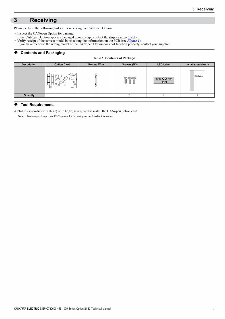
3 ReceivingPlease perform the following tasks after receiving the CANopen Option:• Inspect the CANopen Option for damage.
If the CANopen Option appears damaged upon receipt, contact the shipper immediately.• Verify receipt of the correct model by checking the information on the PCB (see Figure 1).• If you have received the wrong model or the CANopen Option does not function properly, contact your supplier.
◆ Contents and PackagingTable 1 Contents of Package
◆ Tool RequirementsA Phillips screwdriver PH1(#1) or PH2(#2) is required to install the CANopen option card.
Note: Tools required to prepare CANopen cables for wiring are not listed in this manual.
Description: Option Card Ground Wire Screws (M3) LED Label Installation Manual
–
Quantity: 1 1 3 1 1
ERR RUNMANUAL

8 YASKAWA ELECTRIC SIEP C730600 45B 1000-Series Option SI-S3 Technical Manual
4 CANopen Option Components
4 CANopen Option Components
◆ CANopen OptionFigure 1
Figure 1 Option Card
◆ Communication ConnectorThe CANopen Option is connected to the network using a 9 pin D-sub connector. The pin assignment is explained in Table 2.
Table 2 Communication connector (9 pin D-sub)
A – Communication cable connector (9 pin D-sub)
<1> Refer to CANopen Option Status LEDs on page 9 for details on the LEDs.<2> The ground wire provided in the option shipping package must be connected during installation.
E – LED (ERR) <1>
B – Connector (CN5) F – Model numberC – Installation hole G – Ground terminal
(installation hole) <2>D – LED (RUN) <1>
CANopen Connector Pin Signal Description1 – –2 CAN_L CAN_L bus line (dominant low)3 CAN_GND CAN Ground4 – –5 CAN_SHLD CAN shield6 – –7 CAN_H CAN_H bus line (dominant high)8 – –9 – –– CAN_SHLD CAN shield
Underside
BA
C
D
EG
SI-S3
FLooking from the connector
1
5
6
9
78
234

4 CANopen Option Components
YASKAWA ELECTRIC SIEP C730600 45B 1000-Series Option SI-S3 Technical Manual 9
◆ CANopen Option Status LEDsThe CANopen Option has two LEDs that indicate the option card or communication status. The indications are conform with the DS303, Part 3: Indicator Specification.
Table 3 Understanding the Status LEDs
Figure 2 explains the indicator flash rates.Figure 2
Figure 2 LED Flash Rates and Meaning
LED
<1> Available in option card software version 3102 and later.
Color Display Meaning
RUN Green
On Operational StateBlinking Pre-Operational State
Single flash StoppedFlickering <1> Automatic bit rate detection in progress (alternately flickering with ERR LED)
ERR Red
On Bus offBlinking Bus initialization failed (parameter setting error)
Single flash Fault has occurredReceiving CAN error frame (too many error frames)
Double flash Guard / Heartbeat event has occurredFlickering <1> Automatic bit rate detection in progress (alternately flickering with RUN LED)
Off Online
Blinking(200 ms)
ON
1s 2s
ON
ON
ON
ON
ERR
RUN
ERR
RUN
Single flash
ERRDouble flash
ERR
RUN
Flickering (50 ms)
10 YASKAWA ELECTRIC SIEP C730600 45B 1000-Series Option SI-S3 Technical Manual
5 Installation Procedure
5 Installation Procedure
◆ Section Safety
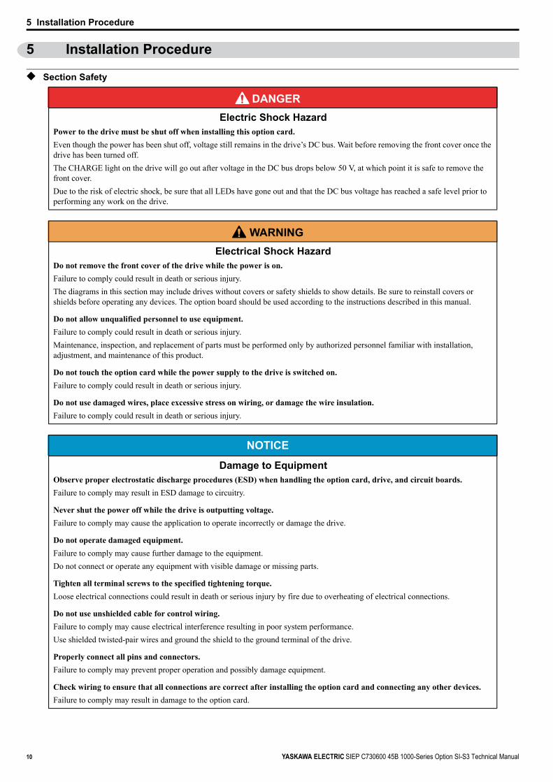
DANGER Electric Shock Hazard
Power to the drive must be shut off when installing this option card.Even though the power has been shut off, voltage still remains in the drive’s DC bus. Wait before removing the front cover once the drive has been turned off.The CHARGE light on the drive will go out after voltage in the DC bus drops below 50 V, at which point it is safe to remove the front cover.Due to the risk of electric shock, be sure that all LEDs have gone out and that the DC bus voltage has reached a safe level prior to performing any work on the drive.
W ARNING Electrical Shock Hazard
Do not remove the front cover of the drive while the power is on.Failure to comply could result in death or serious injury.The diagrams in this section may include drives without covers or safety shields to show details. Be sure to reinstall covers or shields before operating any devices. The option board should be used according to the instructions described in this manual.
Do not allow unqualified personnel to use equipment.Failure to comply could result in death or serious injury.Maintenance, inspection, and replacement of parts must be performed only by authorized personnel familiar with installation, adjustment, and maintenance of this product.
Do not touch the option card while the power supply to the drive is switched on.Failure to comply could result in death or serious injury.
Do not use damaged wires, place excessive stress on wiring, or damage the wire insulation.Failure to comply could result in death or serious injury.
NOTICE
Damage to EquipmentObserve proper electrostatic discharge procedures (ESD) when handling the option card, drive, and circuit boards.Failure to comply may result in ESD damage to circuitry.
Never shut the power off while the drive is outputting voltage.Failure to comply may cause the application to operate incorrectly or damage the drive.
Do not operate damaged equipment.Failure to comply may cause further damage to the equipment.Do not connect or operate any equipment with visible damage or missing parts.
Tighten all terminal screws to the specified tightening torque.Loose electrical connections could result in death or serious injury by fire due to overheating of electrical connections.
Do not use unshielded cable for control wiring.Failure to comply may cause electrical interference resulting in poor system performance.Use shielded twisted-pair wires and ground the shield to the ground terminal of the drive.
Properly connect all pins and connectors.Failure to comply may prevent proper operation and possibly damage equipment.
Check wiring to ensure that all connections are correct after installing the option card and connecting any other devices.Failure to comply may result in damage to the option card.

5 Installation Procedure
YASKAWA ELECTRIC SIEP C730600 45B 1000-Series Option SI-S3 Technical Manual 11
◆ Prior to Installing the Option CardPrior to installing the CANopen Option, wire the drive and make necessary connections to the drive terminals. For more information on wiring and connecting the drive, refer to the technical manual for the drive the CANopen option card is connected to. Verify that the drive runs normally without the option installed.
◆ Installing the Option Card
1. Shut off power to the drive, wait the appropriate amount of time for voltage to dissipate, then remove the operator and front cover. Refer to the drive technical manual for direction on removing the front cover.
2. Insert the CN5 connector on the option card into the CN5-A connector on the drive, then fasten it into place using one of the screws included with the option card.Connect the ground lead line to the ground terminal using one of the screws delivered with the option card.
Note: There are only two screw holes on the drive for ground terminals. If three option cards are connected, two of the lead lines will need to share the same ground terminal.Figure 3
Figure 3 Installing the Option Card
3. Prepare network cable connectors like explained in Figure 5 on page 12. Apply a termination resistor like explained in Figure 6 on page 12 if the drive is the last node in the network.In the drives CIMR-A 2A0004 to 0040 and 4A0002 to 0023 the network cable must be routed to the outside through the drive top cover. Use a pair of wire cutters to cut out the perforated openings at the left side of the top cover. Make sure no sharp edges that can damage the cable remain.Drives 2A0056 to 0211, 4A0031 to 0165 have enough space to keep all wiring inside the unit.
Figure 4
Figure 4 Wiring space
4. Plug in the network cable connector and fix it using the screws at the side of connector.5. Place the front cover back onto the drive as it was before.
Note: 1. Take care when wiring the option card so that the front cover easily fits back onto the drive.2. Install Cable Cover option to maintain the drive Enclosure Type.
6. Attach the LED label packaged with the option card as shown in Figure 3.7. Switch on the drive power supply.
An “AEr” Alarm message indicating that the node address is set to 0 will appear on the display. Set the node address in parameter F6-35. Set the communication speed in parameter F6-36.
8. Cycle the power supply to activate the changed settings. Installation completed.
A – Insert connector CN5 here G – Lead lineB – Option card H – Drive grounding terminal (FE)C – Front cover I – Connector CN5-AD – Operator J – Connector CN5-BE – LED label K – Connector CN5-CF – Use wire cutters to create an
opening for cable lines
A – Opening for cable lines(CIMR-A 2A0004 to 0040, 4A0002 to 0023)
B – Space for wiring (CIMR-A 2A0056 to 0211, 4A0031 to 0165)
G
K
A
B
D
J
I
H
F
ERR RUN E
C
A
B
5 Installation Procedure
12 YASKAWA ELECTRIC SIEP C730600 45B 1000-Series Option SI-S3 Technical Manual
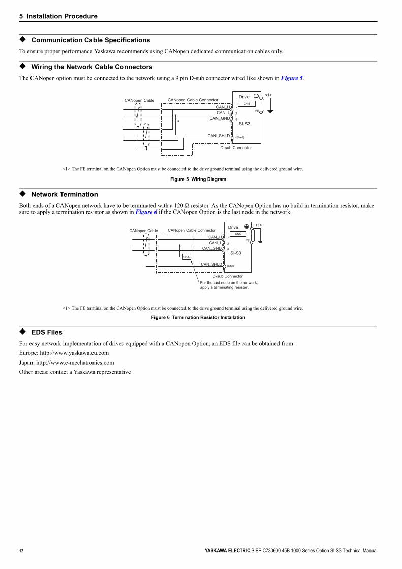
◆ Communication Cable SpecificationsTo ensure proper performance Yaskawa recommends using CANopen dedicated communication cables only.
◆ Wiring the Network Cable ConnectorsThe CANopen option must be connected to the network using a 9 pin D-sub connector wired like shown in Figure 5.Figure 5
Figure 5 Wiring Diagram
◆ Network TerminationBoth ends of a CANopen network have to be terminated with a 120 Ω resistor. As the CANopen Option has no build in termination resistor, make sure to apply a termination resistor as shown in Figure 6 if the CANopen Option is the last node in the network. Figure 6
Figure 6 Termination Resistor Installation
◆ EDS FilesFor easy network implementation of drives equipped with a CANopen Option, an EDS file can be obtained from:Europe: http://www.yaskawa.eu.comJapan: http://www.e-mechatronics.comOther areas: contact a Yaskawa representative
<1> The FE terminal on the CANopen Option must be connected to the drive ground terminal using the delivered ground wire.
<1> The FE terminal on the CANopen Option must be connected to the drive ground terminal using the delivered ground wire.
D-sub Connector
CAN_SHLD
CAN_LCAN_GND
CAN_H
CANopen Cable Connector
(Shell)
CANopen CableDrive
SI-S3
7
2
3
CN5
FE
<1>
Drive
D-sub Connector
SI-S3
CAN_SHLD
CAN_LCAN_GND
CAN_H 7
2
3
CANopen Cable ConnectorCN5
FE
(Shell)
<1>CANopen Cable
120Ω
For the last node on the network,apply a terminating resister.

6 Related Parameters
YASKAWA ELECTRIC SIEP C730600 45B 1000-Series Option SI-S3 Technical Manual 13
6 Related ParametersThe following parameters are used to set up the drive for operation with the option.Confirm proper setting of the all parameters in Table 4 before starting network communications.
Table 4 Related Parameters
No.
<1> To start and stop the drive from a CANopen master device using serial communications, set b1-02 to 3. To control the frequency reference of the drive via the master device, set b1-01 to 3.
<2> The default value depends on the drive used and the drive software version. For details refer to the technical manual for the drive.<3> E2-04 is necessary to set up when the Drive Profile DSP402 objects are used.<4> If set to 3, then the drive will continue to operate when an EF0 fault is detected. Take proper safety measures, such as installing an emergency stop switch.<5> This parameter might not appear in certain drives. Furthermore its availability is limited to depending on the control mode selection. For details refer to the technical manual for the drive
the option card is used with.<6> If the drive is set to receive the torque reference/limit from the network (F6-06 = 1) make sure the value is set appropriately by the controller. If no torque reference/limit value is entered
the motor will not produce torque.<7> Power must be cycled in order to activate the setting after changes.<8> All node addresses must be unique. If a node address is set to 0, then the ERR light will flash, and AEr will appear on the keypad screen to indicate that an address setting error has
occurred.<9> Disabled in option card software versions up to 3101. Automatic bit rate detection is available in option card software versions 3102 and later.<10> For the models CIMR-AC A, the default value is 0 when using the drive software version S1015 and later.
For the other models, the default value is 6.<11> Changing o1-03 changes the units for input object 2010 (Hex) (frequency reference), output object 2110 (Hex) (output frequency) and 2200 (Hex) (motor speed). Furthermore o1-03
must be set to 2 and E2-04 must be set to the correct value in order to use the Drive Profile DSP402.
Name Description Default
b1-01<1>
Frequency Reference Selection
Selects the frequency reference input source0: Operator - Digital preset speed d1-01 to d1-171: Terminals - Analog input terminals2: MEMOBUS/Modbus communications 3: Option card4: Pulse Input (Terminal RP)
<2>
b1-02<1>
Run Command Selection
Selects the run command input source0: Digital Operator - RUN and STOP keys1: Digital input terminals S2: MEMOBUS/Modbus communications 3: Option card
1
E2-04<3>
Motor 1 Motor Poles Set the number of motor poles described on the motor nameplate.2 to 48 4
F6-01 Operation Selection after Communications Error
Determines drive response when a bUS error is detected during communications with the CANopen Option0: Ramp to Stop 1: Coast to Stop2: Fast-Stop3: Alarm Only <4>
1
F6-02 External Fault Detection Conditions (EF0)Sets the condition for external fault detection (EF0)0: Always detected1: Detected only during operation
0
F6-03 Stopping Method for External Fault from Communication Option Board
Determines drive response for external fault input (EF0) detection during CANopen communication0: Ramp to Stop 1: Coast to Stop2: Fast-Stop3: Alarm Only <4>
1
F6-06<5>
Torque Reference/Torque Limit selection from Communications Option
0: Torque reference/torque limit via network communications are disabled.1: Torque reference/torque limit via network communications are enabled. <6>
0
F6-07 NetRef/ComRef Selection Function 0: Multi-step speed reference disabled (F7 mode)1: Multi-step speed reference allowed (V7 mode) 0
F6-08 Reset Communication Related Parameters
Determines if communication-related parameters are set back to their original default values when the drive is initialized.0: Do not reset F6- and F7- parameters when the drive is initialized using parameter
A1-03.1: Rest F6- and F7- parameters when the drive is initialized using parameter A1-03.
Note: Setting this parameter does not affect communication-related parameters. Setting this parameter only determines if communication-related parameters (F6- and F7- ) are also reset when A1-03 is used to initialize the drive.
0
F6-35<7> <8>
Node Address 0 to 126 0
F6-36<7>
Communication Speed
0: Automatic Bit Rate Detection <9>1: 10 kbps2: 20 kbps3: 50 kbps4: 125 kbps 5: 250 kbps 6: 500 kbps7: 800 kbps8: 1 Mbps
<10>
o1-03<11>
Digital Operator Display Selection
Sets the units to display the frequency reference and output frequency.0: 0.01 Hz 1: 0.01% (100% = E1-04) 2: r/min (enter the number of motor poles to E2-04/E4-04/E5-04) 3: User defined by parameters o1-10 and o1-11
<2>

14 YASKAWA ELECTRIC SIEP C730600 45B 1000-Series Option SI-S3 Technical Manual
7 Bit Rate and Node ID Setup
7 Bit Rate and Node ID Setup
◆ Bit Rate SetupIn order to communicate with the drive, the bit rate set in the SI-S3 option card must match the bit rate used in the network. The bit rate can be selected manually by using a drive parameter. The SI-S3 can also be set up for automatic bit rate detection.
■ Setting the Bit Rate ManuallySelect the correct bit rate in drive parameter F6-36. After changing F6-36, cycle the drive power supply to enable the changes.
Table 5 Bit Rate Setting
■ Using Automatic Bit Rate DetectionNote: This function is available in option card software version 3102 and later.
Set drive parameter F6-36 to 0 to enable automatic bit rate detection and cycle the drive power supply.When set to automatic bit rate detection, after power up the SI-S3 will listen to messages on the bus and adjust its bit rate setting automatically. When the bit rate is found the SI-S3 will enter pre-operational status and transmit a boot up message containing the drive's node ID. The SI-S3 will not send any messages until the bit rate is detected.As long as the automatic bit rate detection is in progress, the RUN and ERR LEDs on the SI-S3 option card will flicker alternatingly.
Note: 1. There must be bus traffic that the SI-S3 can listen to in order to detect the bit rate. If there is low traffic, the bit rate detection might take a long time.2. The bit rate detected by the SI-S3 is not automatically saved. When cycling the drive power supply, the SI-S3 will perform bit rate detection again.3. Besides the master, there must be at least one other node in the network that is set to the correct bit rate. For example, the bit rate cannot be detected if the network consists of
a master that is set up for a certain bit rate (controller) and one or multiple drives with an SI-S3 option card set to auto bit rate detection.
◆ Node ID SetupThe node ID can be set in drive parameter F6-35. The value range is 1 to 126. Each node ID may only be used once in the network.After changing F6-35, cycle the drive power supply to enable the changes.
Note: When the node is set to 0, the ERR light will flash and “AEr” will appear on the drive digital operator to indicate that an address setting error has occurred.
No.
<1> Disabled in option card software versions up to 3101. Automatic bit rate detection is available in option card software versions 3102 and later.<2> For the models CIMR-AC A, the default value is 0 when using the drive software version S1015 and later.
For the other models, the default value is 6.
Name Description Default
F6-36 Communication Speed
0: Automatic Bit Rate Detection <1>1: 10 kbps2: 20 kbps3: 50 kbps4: 125 kbps 5: 250 kbps 6: 500 kbps7: 800 kbps8: 1 Mbps
<2>
8 Object Dictionary
YASKAWA ELECTRIC SIEP C730600 45B 1000-Series Option SI-S3 Technical Manual 15
8 Object Dictionary
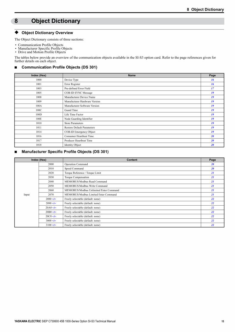
◆ Object Dictionary OverviewThe Object Dictionary consists of three sections: • Communication Profile Objects• Manufacturer Specific Profile Objects• Drive and Motion Profile ObjectsThe tables below provide an overview of the communication objects available in the SI-S3 option card. Refer to the page references given for further details on each object.
■ Communication Profile Objects (DS 301)
■ Manufacturer Specific Profile Objects (DS 301)
Index (Hex) Name Page1000 Device Type 161001 Error Register 161003 Pre-defined Error Field 171005 COB-ID SYNC Message 191008 Manufacturer Device Name 191009 Manufacturer Hardware Version 19100A Manufacturer Software Version 19100C Guard Time 19100D Life Time Factor 19100E Node Guarding Identifier 191010 Store Parameters 191011 Restore Default Parameters 191014 COB-ID Emergency Object 191016 Consumer Heartbeat Time 201017 Producer Heartbeat Time 201018 Identity Object 20
Index (Hex) Content Page
Input
2000 Operation Command 202010 Speed Command 202020 Torque Reference / Torque Limit 212030 Torque Compensation 212040 MEMOBUS/Modbus Read Command 212050 MEMOBUS/Modbus Write Command 212060 MEMOBUS/Modbus Unlimited Enter Command 212070 MEMOBUS/Modbus Limited Enter Command 21
2080 <1> Freely selectable (default: none) 222090 <1> Freely selectable (default: none) 2220A0 <1> Freely selectable (default: none) 2220B0 <1> Freely selectable (default: none) 2220C0 <1> Freely selectable (default: none) 223000 <1> Freely selectable (default: none) 223100 <1> Freely selectable (default: none) 22

8 Object Dictionary
16 YASKAWA ELECTRIC SIEP C730600 45B 1000-Series Option SI-S3 Technical Manual
■ Drives and Motion Profile Objects (DSP 402)The drive supports the Drive and Motion Profile DSP 402 Velocity Mode. Before using the Velocity Mode objects the following parameters have to be set up in the drive:• The motor pole number must be set up in E2-04.• The frequency reference and output frequency display unit has to be set to min-1 by setting parameter o1-03 = 2.If these settings are not done properly, the Velocity Mode objects cannot be used or deliver wrong data.
◆ Communication Profile Objects (DS 301)
■ 1000 (Hex) - Device TypeThis object describes the type of device and its functionality. It is composed of a first 16 bit field that describes the device profile used and a second 16 bit field that gives additional information regarding optional functionality.
■ 1001 (Hex) - Error RegisterThis register shows the fault status of the device. If any errors occurs in the device bit 0 (generic error) is set to one.
Output
2100 Drive Status 222101 <1> Drive Status (Change of State filter support) 22
2110 Output Frequency 222111 <1> Output Frequency (Change of State filter support) 22
2120 Output Current 232121 <1> Output Current (Change of State filter support) 23
2130 Output Torque 232131 <1> Output Torque (Change of State filter support) 23
2140 MEMOBUS/Modbus Read Command Response 232150 MEMOBUS/Modbus Write Command Response 23
2155 <1> PDO Parameter Write Response 232160 MEMOBUS/Modbus Not Limited Enter Command Response 23
2180 <1> Freely selectable (default: Input terminal status) 242190 <1> Freely selectable (default: Analog input 1 monitor) 2421A0 <1> Freely selectable (default: none) 2421B0 <1> Freely selectable (default: none) 2421C0 <1> Freely selectable (default: none) 2421D0 <1> Freely selectable (default: none) 2421E0 <1> Freely selectable (default: none) 2421F0 <1> Freely selectable (default: none) 24
2200 Motor Speed <2> 242201 <1> Motor Speed (Change of State filter support) <2> 24
<1> Available in option card software version 3102 and later.<2> Units for motor speed are determined by o1-03. If the control mode for the drive is set to V/f control (A1-02=0) and V/f control with simple PG feedback is disabled (H6-01≠3), then the
motor speed will be 0.
Object Type
<1> YASKAWA specifies this object as the drive digital output monitor. (Input from the network)<2> YASKAWA specifies this object as the drive digital inputs. (Output to the network)
Index (Hex) Name Page
Common Entries60FD Digital Inputs <1> 2660FE Digital Outputs <2> 26
Device Control6040 Controlword 246041 Statusword 256061 Modes of operation display 26
Velocity Mode
6042 vl target velocity 256043 vl velocity demand 256044 vl control effort 256046 vl velocity min max amount 256048 vl velocity acceleration 256049 vl velocity deceleration 25604A vl velocity quick stop 25604C vl dimension factor 25604D vl pole number 26
Index (Hex) Subindex Content Access PDO Mapping Value Range1000 – Device type Read Only No Unsigned 32
Index (Hex) Subindex Content Access PDO Mapping Value Range1001 – Error register Read Only Possible Unsigned 8
Index (Hex) Content Page

8 Object Dictionary
YASKAWA ELECTRIC SIEP C730600 45B 1000-Series Option SI-S3 Technical Manual 17
■ 1003 (Hex) - Pre-defined Error FieldThis register provides a history of errors that occurred in the drive and have been signalized via the Emergency object. Subindex 0 contains the number of errors. Subindexes 1 to FF contains a rolling list of error codes where subindex 1 always contains the last occurred error. Refer to Table 6 for a list of possible error codes.Writing a 0 to subindex 0 will reset the error field.
Index (Hex)
<1> For details of the error codes, refer to Table 6.
Subindex Content Access PDO Mapping Value Range
10030 Number of errors Read / Write
NoUnsigned 8
1 Standard error field <1> Read Only Unsigned 32

8 Object Dictionary
18 YASKAWA ELECTRIC SIEP C730600 45B 1000-Series Option SI-S3 Technical Manual
Table 6 CANopen Option Card Error Codes
Error Code (Hex) Content Drive Display
2220 Over current oC
2221 Drive overload oL2
2310 Motor overload oL1
2311 Overtorque detection 1 oL3
2312 Overtorque detection 2 oL4
2330 Ground fault GF
3130 Input phase loss PF
3210 DC bus overvoltage ov
3220 DC bus undervoltage Uv1
3221 DC bus charging circuit fault Uv3
3300 Output phase loss LF
4210 Heatsink overheat oH1
4280 Heatsink overheat oH
4310 Motor overheat (PTC input) oH4
4410 Internal braking resistor overheat rH
5200 Control power supply undervoltage Uv2
5300 Digital operator disconnected oPr
5420 Braking transistor fault rr5441 External fault 3 EF35442 External fault 4 EF45443 External fault 5 EF55444 External fault 6 EF65445 External fault 7 EF75446 External fault 8 EF85481 Fault input from option card EF05530 EEPROM error Err6301 Error during object content selection -7180 Motor over speed (control mode using PG) oS7305 PG fault (control mode using PG) PGo8313 Zero servo fault SvE8321 Speed deviation (control mode using PG) dEvFF01 Motor overheat alarm oH3FF02 PID feedback lost FbLFF03 Undertorque detected 1 UL3FF04 Undertorque detected 2 UL4FF05 High slip braking OL oL7FF06 Control fault CFFF07 BUS error bUSFF08 MEMOBUS/Modbus Error CEFF0D External fault at input terminal S1 EF1FF0E External fault at input terminal S2 EF2FF32 Z-phase pulse fall detection (Closed Loop Vector for PM motors) dv1FF33 Z-phase noise fault detection (Closed Loop Vector for PM motors) dv2FF34 Inversion detection (Closed Loop Vector for PM motors) dv3FF35 Inversion prevention detection (Closed Loop Vector for PM motors) dv4FF36 Output current imbalance LF2FF37 Pullout detection 2 SToFF38 PG Disconnect PGoFF3B Too many speed search restarts SErFF41 PID feedback loss FbHFF44 Mechanical weakening detection 1 oL5FF45 Mechanical weakening detection 2 UL5FF46 Current offset fault CoFFF47 Programming Error 1 PE1FF49 Current offset fault dWFLFF4E Dynamic Braking Resistor Selection Fault RFFF4F Dynamic Braking Transistor Overload BOLFF52 Node Setup Error nSE

8 Object Dictionary
YASKAWA ELECTRIC SIEP C730600 45B 1000-Series Option SI-S3 Technical Manual 19
■ 1005 (Hex) - COB-ID SYNC Message This object defines the COB-ID of the synchronization object (SYNC), and whether the device generates the SYNC message.
■ 1008 (Hex) - Manufacturer Device NameThis object contains the manufacturer device name.
■ 1009 (Hex) - Manufacturer Hardware VersionThis object contains the manufacturer hardware version.
■ 100A (Hex) - Manufacturer Software VersionThis object contains the Manufacturer software version.
■ 100C (Hex) - Guard TimeThis object contains the guard time.
■ 100D (Hex) - Life Time Factor This object contains the life time factor. Multiplied with the guard time, it sets the time within the SI-S3 option expects a node guarding message. If the node guarding message is not received an error will be generated.
■ 100E (Hex) - Node Guarding Identifier This object defines the identifier for the node guarding.
■ 1010 (Hex) - Store ParametersBy writing "save" (s = 73H, a = 61H, v = 76H, e = 65H) to this object, the CANopen Option settings are saved in the non-volatile memory. The CANopen Option will operate using these settings when a Reset Node or Reset Communications command is performed, or when the power supply is cycled.
■ 1011 (Hex) - Restore Default ParametersWriting "load" (l = 6CH, o = 6FH, a = 61H, d = 64H) to this object will restore the CANopen Option default settings.
■ 1014 (Hex) - COB-ID Emergency ObjectThis object defines the COB-ID of the emergency object.
Index (Hex) Subindex Content Access PDO Mapping Value Range1005 – COB-ID SYNC message Read / Write No Unsigned 32
Index (Hex) Subindex Content Access PDO Mapping Value Range 1008 – Manufacturer device name Read Only No Visible string
Index (Hex) Subindex Content Access PDO Mapping Value Range
1009 – Manufacturer hardware version Read Only No Visible string
Index (Hex) Subindex Content Access PDO Mapping Value Range
100A – Manufacturer software version Read Only No Visible string
Index (Hex) Subindex Content Access PDO Mapping Value Range Units 100C – Guard time Read / Write No Unsigned 16 1 ms
Index (Hex) Subindex Content Access PDO Mapping Value Range 100D – Life time factor Read / Write No Unsigned 8
Index (Hex) Subindex Content Access PDO Mapping Value Range 100E – Node guarding identifier Read Only No Unsigned 32
Index (Hex) Subindex Content Access PDO Mapping Value Range1010 1 Store parameters Read / Write No Unsigned 32
Index (Hex) Subindex Content Access PDO Mapping Value Range1011 1 Restore default parameters Read / Write No Unsigned 32
Index (Hex) Subindex Content Access PDO Mapping Value Range1014 – COB-ID emergency object Read Only No Unsigned 32

8 Object Dictionary
20 YASKAWA ELECTRIC SIEP C730600 45B 1000-Series Option SI-S3 Technical Manual
■ 1016 (Hex) - Consumer Heartbeat TimeThis object defines the Consumer heartbeat time. It must be set to a higher value than the producer heartbeat time set in the master. When set to 0, consumer heartbeat is disabled.
■ 1017 (Hex) - Producer Heartbeat TimeThis object determines the cycle time the CANopen Option uses to produce a heartbeat signal. When set to 0, the SI-S3 does not produce a heartbeat signal.
■ 1018 (Hex) - Identity ObjectThis object contains general information about the drive.
◆ Manufacturer Specific Profile Objects (DS 301)The SI-S3 option card offers the manufacturer specific objects listed below. These objects are specific to Yaskawa products and therefore not available on other CANopen products.The manufacturer-specific object list consists of objects that have predefined, non-changeable content and objects that are freely configurable. The content of freely configurable objects can be determined by linking these objects to drive parameters, monitors or MEMOBUS/Modbus registers (refer to Selectable Object Content on page 27). Input objects are processed in a cycle of 2 ms. Output objects are, depending on the object, updated in a cycle of either 2 ms or 8 ms. The update cycle cannot be changed.Some of the output objects support a Change of State filter that can be used to reduce the bus traffic when quickly-changing values such as the output current and motor speed are mapped to TxPDOs with Change of State (transmission type FE (Hex)) enabled. Refer to Change of State Filter on page 29 and Transmission Type FE (Hex) for Transmit PDOs on page 29 for details.
Note: Freely configurable object content and the object Change of State filter function are available in option card software version 3102 and later.
■ 2000 (Hex) - Operation CommandThis object is used to start and stop the drive, to control the multi-function digital input terminals, and to trigger and reset faults.
■ 2010 (Hex) - Speed Reference/Speed LimitSets the speed reference or speed limit. The unit of this value depends on the setting of the drive parameter o1-03. The value will be used as the speed reference for speed control (d5-01 = 0) or as the speed limit in torque control (d5-01 = 1).
Note: The availability of the torque control function depends on the drive and the selected control mode. For details, refer to the technical manual for the drive.
Index (Hex) Subindex Content Access PDO Mapping Value Range Units1016 1 Consumer heartbeat time Read / Write No Unsigned 32 1 ms
Index (Hex) Subindex Content Access PDO Mapping Value Range Units1017 – Producer heartbeat time Read / Write No Unsigned 16 1 ms
Index (Hex) Subindex Content Access PDO Mapping Value Range1018 1 Identity object Read Only No Unsigned 32
Index (Hex) Subindex Content Access PDO Mapping Data Length2000 0 Operation Command Read / Write Possible 2 byte
Bit No. (Hex) Description Function 0 Forward Run 1: Forward run, 0: Stop (Enabled when b1-02=3) 1 Reverse Run 1: Reverse run, 0: Stop (Enabled when b1-02=3) 2 Terminal S3 Function Multi-Function Input: H1-03 3 Terminal S4 Function Multi-Function Input: H1-04 4 Terminal S5 Function Multi-Function Input: H1-05 5 Terminal S6 Function Multi-Function Input: H1-06 6 Terminal S7 Function Multi-Function Input: H1-07 7 Terminal S8 Function Multi-Function Input: H1-08 8 External Fault (EF0) 1: External Fault Input (EF0) 9 Fault Reset 1: Fault Reset
A to F Not used
Index (Hex) Subindex Content Access PDO Mapping Data Length2010 0 Speed command Read / Write Possible 2 byte

8 Object Dictionary
YASKAWA ELECTRIC SIEP C730600 45B 1000-Series Option SI-S3 Technical Manual 21
■ 2020 (Hex) - Torque Reference/Torque LimitThis object sets the torque reference or the torque limit in units of 0.1%.To use this object, set drive parameter F6-06 to 1. The value will be used as the torque reference for torque control (d5-01 = 1) or as the torque limit in speed control (d5-01 = 0).
Note: The availability of the torque control and torque limit function depends on the drive and the selected control mode. For details, refer to the technical manual for the drive.
■ 2030 (Hex) - Torque CompensationThis object sets the torque compensation in units of 0.1%.
■ 2040 (Hex) - MEMOBUS/Modbus Read RequestThis object can be used to read out the content of drive MEMOBUS/Modbus registers. The address of the MEMOBUS/Modbus must be written in byte 3 and 4 of Subindex 1, bytes 1 and 2 have to be set to 0. After sending a MEMOBUS/Modbus Read Request to the drive, the MEMOBUS/Modbus register content can be read out from object 2140H.For more details on MEMOBUS/Modbus address and data, refer to the MEMOBUS/Modbus Data Table in Appendix C of the technical manual for the drive.
■ 2050 (Hex) - MEMOBUS/Modbus Write RequestUsing this object, drive MEMOBUS/Modbus registers can be written. The data must be written in byte 1 and 2 of Subindex 1, and the MEMOBUS/Modbus address must be written in bytes 3 and 4. After sending a MEMOBUS/Modbus Write Request to the drive, the response can be read from object 2150H.For more details on MEMOBUS/Modbus address and data, refer to the MEMOBUS/Modbus Data Table in Appendix C of the technical manual for the drive.
■ 2060 (Hex) - MEMOBUS/Modbus Unlimited ENTER CommandDepending on the drive parameter H5-11 setting, an ENTER command must be used to activate drive parameters changed via MEMOBUS/Modbus Write Commands. The unlimited ENTER command activates parameters in the drive RAM only. If the drive power is cycled, parameter changes are lost. If more than one parameter has been changed, it is enough to send only one ENTER command after the last parameter change. Doing so will activate all changed parameters. This ENTER command can be used without limitations.To execute this type of ENTER command, "save" (73H + 61H + 76H + 65H) must be written in object 2060H, subindex 0.
■ 2070 (Hex) - MEMOBUS/Modbus Limited ENTER CommandDepending on the drive parameter H5-11 setting, an ENTER command must be used to activate drive parameters changed via MEMOBUS/Modbus Write Commands. The limited ENTER command activates parameters in the drive’s RAM and saves them to the EEPROM. When power supply loss occurs or the power supply is cycled, the drive will operate using the saved parameters. If more than one parameter has been changed, it is enough to send only one ENTER command after the last parameter change. Doing so will activate all changed parameters. This type of ENTER command can be applied approximately 100,000 times, and should be used only when necessary.To execute this type of ENTER command, "save" (73H + 61H + 76H + 65H) must be written in object 2070H, subindex 0.
Index (Hex) Subindex Content Access PDO Mapping Data Length2020 0 Torque Reference / Torque Limit Read / Write Possible 2 byte
Index (Hex) Subindex Content Access PDO Mapping Data Length2030 0 Torque Compensation Read / Write Possible 2 byte
Index (Hex) Subindex Content Access PDO Mapping Data Length
2040
0 Number of entries Read Only
Possible
1 byte
1 MEMOBUS/Modbus read request Read / Write2 + 2 byte
0000H + MEMOBUS/Modbus Address
Index (Hex.) Subindex Content Access PDO Mapping Data Length
2050
0 Number of entries Read Only
Possible
1 byte
1 MEMOBUS/Modbus Write request Read / Write2 + 2 byte
MEMOBUS/ModbusData + Address
Index (Hex) Subindex Content Access PDO Mapping Data Length2060 0 Unlimited ENTER command Read / Write Possible 4 byte
Index (Hex) Subindex Content Access PDO Mapping Data Length2070 0 Limited enter command Read / Write Possible 4 byte

8 Object Dictionary
22 YASKAWA ELECTRIC SIEP C730600 45B 1000-Series Option SI-S3 Technical Manual
■ 2080 (Hex) to 3100 (Hex) - Freely Configurable Input ObjectsThe content of these objects can be freely selected by linking them to drive MEMOBUS/Modbus registers. Refer to Selecting the Object Content on page 27 for details.
■ 2100 (Hex) / 2101 (Hex) - Drive StatusThese objects can be used to monitor the drive status. The value in object 2100 (Hex) is not filtered. For the value in object 2101 (Hex) a Change of State filter can be set up as explained in Change of State Filter on page 29.
Table 7 Drive Status
■ 2110 (Hex) / 2111 (Hex) - Output FrequencyThese objects can be used to monitor the output frequency. The value in object 2110 (Hex) is not filtered. For the value in object 2111 (Hex) a Change of State filter can be set up as explained in Change of State Filter on page 29. The units used for the monitor value are determined by drive parameter o1-03.
Index (Hex)
<1> Available in option card software version 3102 and later.<2> Read / Write access when SI-S3 is in the Pre-Operational state and read-only access if the SI-S3 is in the Operational state or if the drive is running.
Subindex Content Default Access PDO Mapping Data Length
2080 <1>
0 Number of entries 2 Read Only No 1 byte1 Value - Read / Write Possible 4 byte2 MEMOBUS/Modbus register address for content 1 and 2 FFFF (Hex) / FFFF (Hex) Read / Write <2> No 4 byte
2090 to 20C0, 3000, and 3100 <1>
0 Number of entries 2 Read Only No 1 byte1 Value - Read / Write Possible 2 byte2 MEMOBUS/Modbus register address for content FFFF (Hex) Read / Write <2> No 2 byte
Index (Hex)
<1> Available in option card software version 3102 and later.<2> For details of the drive status, refer to Table 7.<3> Read / Write access when SI-S3 is in the Pre-Operational state, Read only access if the SI-S3 is in the Operational state or if the drive is running.
Subindex Content Default Access PDO Mapping Data Length Update Cycle2100 0 Drive Status <2> - Read Only Possible 2 byte 2 ms
2101 <1>
0 Number of entries 4 Read Only No 1 byte -1 Drive Status <2> - Read Only Possible 2 byte 2 ms2 MEMOBUS/Modbus register address for content 00FC (Hex) Read Only No 2 byte
-3 Filter value 0 Read / Write <3> No 2 byte4 Value filter type 1 (Bitmask) Read / Write <3> No 2 byte
Bit No. (Hex) Function Description0 During Run 1: During Run 0: During Stop1 During Zero Speed 1: During Zero Speed2 Reverse Running 1: During Reverse Running 0: During Forward Running3 During Fault Reset Signal Input 1: During Fault Reset Signal Input4 During Speed Agree 1: During Speed Agree5 During Drive Ready 1: During Drive Ready 0: Not Ready6 During Alarm 1: During Alarm7 During Fault 1: During Fault8 During Operation Error 1: During Operation Error9 During Momentary Power Loss 1: During Momentary Power Loss 0: During Power LossA NetCtrl Status 1: NetCtrlB Digital Output 1 Status (function set in drive parameter H2-01) 1: ON 0: OFFC Digital Output 2 Status (function set in drive parameter H2-02) 1: ON 0: OFFD Digital Output 3 Status (function set in drive parameter H2-03) 1: ON 0: OFFE Motor 2 Selected 1: Motor 2 SelectedF Zero-Servo End 1: Zero-Servo End
Index (Hex)
<1> Available in option card software version 3102 and later.<2> Read / Write access when SI-S3 is in the Pre-Operational state, Read only access if the SI-S3 is in the Operational state or if the drive is running.
Subindex Content Default Access PDO Mapping Data Length Update Cycle2110 0 Output Frequency - Read Only Possible 2 byte 2 ms
2111 <1>
0 Number of entries 4 Read Only No 1 byte -1 Output Frequency - Read Only Possible 2 byte 2 ms2 MEMOBUS/Modbus register address for content 0041 (Hex) Read Only No 2 byte
-3 Filter value FFFF (Hex) Read / Write <2> No 2 byte4 Value filter type 0 (Analog) Read / Write <2> No 2 byte

8 Object Dictionary
YASKAWA ELECTRIC SIEP C730600 45B 1000-Series Option SI-S3 Technical Manual 23
■ 2120 (Hex) / 2121 (Hex) - Output CurrentThese objects can be used to monitor the drive output current in amperes. The current value resolution is the same as in drive monitor U1-03 (For details, refer to the Technical Manual for the drive). The value in object 2120 (Hex) is not filtered. For the value in object 2121 (Hex), a Change of State filter can be set up as explained in Change of State Filter on page 29.
■ 2130 (Hex) / 2131 (Hex) - Output Torque ReferenceThese objects can be used to monitor the output torque reference. The value in object 2130 (Hex) is not filtered. For the value in object 2131 (Hex), a Change of State filter can be set up as explained in Change of State Filter on page 29.The availability of this object content depends on the drive control mode. If the selected control mode does not support this monitor (equal to drive monitor U1-09), the torque reference monitor value will be 0. Refer to the drive technical manual for details.
■ 2140 (Hex) - MEMOBUS/Modbus Read ResponseThis object contains the data of the drive MEMOBUS/Modbus register specified in object 2040 (Hex). Bytes 1 and 2 of subindex 1 will contain the data, and bytes 3 and 4 will contain the MEMOBUS/Modbus Address that was read.
■ 2150 (Hex) - MEMOBUS/Modbus Write ResponseThis object contains the response from the drive when writing a drive parameter with a MEMOBUS/Modbus write command (object 2050 (Hex)). Bytes 1 and 2 of subindex 1 will contain the data that was written, and bytes 3 and 4 will contain the MEMOBUS/Modbus Address that was written to.
■ 2155 (Hex) - PDO Parameter Write ResponseNote: Available in option card software version 3102 and later.
This object contains the response from the drive when writing a drive parameter directly using a RxPDO. Byte 1 contains the lower byte and byte 2 contains the higher byte of the message identifier (COB-ID) for the message that contains the parameter write request. Byte 3 contains the number of errors. This object can only be read if the SI-S3 option is in the Operational state.Refer to Accessing Drive Parameters, Monitors and Control Registers Using PDOs on page 31 for details on writing parameters using PDOs.
■ 2160 (Hex) - MEMOBUS/Modbus Not Limited Enter Command ResponseThis object contains the response from the drive when writing an Enter command using object 2060 (Hex).
Index (Hex)
<1> Available in option card software version 3102 and later.<2> Read / Write access when SI-S3 is in Pre-Operational state, Read only access if the SI-S3 is in the Operational state or if the drive is running.
Subindex Content Default Access PDO Mapping Data Length Update Cycle2120 0 Output Current - Read Only Possible 2 byte 8 ms
2121 <1>
0 Number of entries 4 Read Only No 1 byte -1 Output Current - Read Only Possible 2 byte 8 ms2 MEMOBUS/Modbus register address for content 00FB (Hex) Read Only No 2 byte
-3 Filter value FFFF (Hex) Read / Write <2> No 2 byte4 Value filter type 0 (Analog) Read / Write <2> No 2 byte
Index (Hex)
<1> Available in option card software version 3102 and later.<2> Read / Write access when SI-S3 is in Pre-Operational state, Read only access if the SI-S3 is in the Operational state or if the drive is running.
Subindex Content Default Access PDO Mapping Data Length Update Cycle2130 0 Torque Reference - Read Only Possible 2 byte 8 ms
2131 <1>
0 Number of entries 4 Read Only No 1 byte -1 Torque Reference - Read Only Possible 2 byte 8 ms2 MEMOBUS/Modbus register address for content 0048 (Hex) Read Only No 2 byte
-3 Filter value FFFF (Hex) Read / Write <2> No 2 byte4 Value filter type 0 (Analog) Read / Write <2> No 2byte
Index (Hex) Subindex Content Access PDO Mapping Data Length
2140
0 Number of entries
Read Only Possible
1 byte
1 MEMOBUS/Modbus read response2 + 2 byte
MEMOBUS/ModbusData + Address
Index (Hex) Subindex Content Access PDO Mapping Data Length
2150
0 Number of entries
Read Only Possible
1 byte
1 MEMOBUS/Modbus write response2 + 2 byte
MEMOBUS/ModbusData + Address
Index (Hex) Subindex Content Access PDO Mapping Data Length
2155 0 PDO Parameter Write Response (COB-ID of the RxPDO and number of errors) Read Only Possible 3 byte
Index (Hex) Subindex Content Access PDO Mapping Data Length
2160 0 MEMOBUS/Modbus not limited enter command response Read Only Possible 4 byte

8 Object Dictionary
24 YASKAWA ELECTRIC SIEP C730600 45B 1000-Series Option SI-S3 Technical Manual
■ 2180 (Hex) to 21F0 (Hex) - Freely Configurable Output ObjectsNote: These objects are available in option card software version 3102 and later.
The content of these objects can be freely selected by linking them to drive MEMOBUS/Modbus registers. For 2 byte objects a Change of State filter can be applied. Refer to Change of State Filter on page 29 for details.
■ 2200 (Hex) / 2201 (Hex) - Motor SpeedThese objects can be used to monitor the motor speed. The value in object 2200 (Hex) is not filtered. For the value in object 2201 (Hex), a Change of State filter can be set up as explained in Change of State Filter on page 29. The availability of the object content depends on the drive control mode. If the selected control mode does not support this monitor (equal to drive monitor U1-05), the object value will be 0. Refer to the drive technical manual for details.
◆ Drives and Motion Profile Objects (DSP 402)The drive supports Drive and Motion Profile DSP 402 Velocity Mode. Before using Velocity Mode, objects for following parameters must be set up in the drive:• The number of motor poles must be set to E2-04.• The frequency reference and output frequency display unit must be set to r/min by setting parameter o1-03 = 2.If these settings are incorrect, the Velocity Mode objects may be unusable, or the drive might not operate as expected.
Note: Drive and Motion Control (DSP 402) cannot be set or referenced unless o1-03 = 2.
■ 6040 (Hex) - ControlwordThis object sets the device to different states.
Index (Hex)
<1> Read / Write access when SI-S3 is in the Pre-Operational state, Read only access if the SI-S3 is in the Operational state or if the drive is running.
Subindex Content Default Access PDO Mapping Data Length Update Cycle
2180
0 Number of entries 4 Read Only No 1 byte -1 Value Input Terminal Status Read Only Possible 2 byte 8 ms2 MEMOBUS/Modbus register address for content 0049 (Hex) Read / Write <1> No 2 byte
-3 Filter value 0 Read / Write <1> No 2 byte4 Value filter type 1 (Bitmask) Read / Write <1> No 2 byte
2190
0 Number of Entries 4 Read Only No 1 byte -1 Value Analog Input A1 Monitor Read Only Possible 2 byte 8 ms2 MEMOBUS/Modbus register address for content 004E (Hex) Read / Write <1> No 2 byte
-3 Filter value FFFF (Hex) Read / Write <1> No 2 byte4 Value filter type 0 (Analog) Read / Write <1> No 2 byte
21A0
0 Number of entries 4 Read Only No 1 byte -1 Value - Read Only Possible 2 byte 8 ms2 MEMOBUS/Modbus register address for content FFFF (Hex) Read / Write <1> No 2 byte
-3 Filter value FFFF (Hex) Read / Write <1> No 2 byte4 Value filter type 0 (Analog) Read / Write <1> No 2 byte
21B0 to 21E0
0 Number of entries 4 Read Only No 1 byte -1 Value - Read Only Possible 2 byte 2 ms2 MEMOBUS/Modbus register address for content FFFF (Hex) Read / Write <1> No 2 byte
-3 Filter value FFFF (Hex) Read / Write <1> No 2 byte4 Value filter type 0 (Analog) Read / Write <1> No 2byte
21F00 Number of entries 2 Read Only No 1 byte -1 Value - Read Only Possible 4 byte 8 ms2 MEMOBUS/Modbus register address for content 1 and 2 FFFF (Hex)/FFFF (Hex) Read / Write <1> No 4 byte -
Index (Hex)
<1> Available in option card software version 3102 and later.<2> Read / Write access when SI-S3 is in the Pre-Operational state, Read only access if the SI-S3 is in the Operational state or if the drive is running.
Subindex Content Default Access PDO Mapping Data Length Update Cycle2200 0 Motor Speed - Read Only Possible 2 byte 2 ms
2201 <1>
0 Number of Entries 4 Read Only No 1 byte -1 Motor Speed - Read Only Possible 2 byte 2 ms2 MEMOBUS/Modbus register address for content 0044 (Hex) Read Only No 2 byte
-3 Filter value FFFF (Hex) Read / Write <2> No 2 byte4 Value filter type 0 (Analog) Read / Write <2> No 2 byte
Index (Hex) Subindex Content Access PDO Mapping Value Range6040 0 Controlword Read / Write Possible 0...65535
8 Object Dictionary
YASKAWA ELECTRIC SIEP C730600 45B 1000-Series Option SI-S3 Technical Manual 25
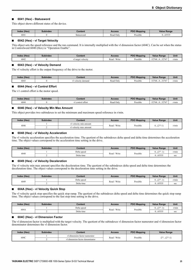
■ 6041 (Hex) - StatuswordThis object shows different states of the device.
■ 6042 (Hex) - vl Target VelocityThis object sets the speed reference and the run command. It is internally multiplied with the vl dimension factor (604C). Can be set when the status in Controlword 6040 (Hex) is “Operation Enable”.
■ 6043 (Hex) - vl Velocity Demand The vl velocity effort is the output frequency of the drive to the motor.
■ 6044 (Hex) - vl Control Effort The v1 control effort is the motor speed.
■ 6046 (Hex) - vl Velocity Min Max Amount This object provides two subindexes to set the minimum and maximum speed reference in r/min.
■ 6048 (Hex) - vl Velocity Acceleration The vl velocity acceleration specifies the acceleration time. The quotient of the subindexes delta speed and delta time determines the acceleration time. The object values correspond to the acceleration time setting in the drive.
■ 6049 (Hex) - vl Velocity DecelerationThe vl velocity min max amount specifies the deceleration time. The quotient of the subindexes delta speed and delta time determines the deceleration time. The object values correspond to the deceleration time setting in the drive.
■ 604A (Hex) - vl Velocity Quick StopThe vl velocity quick stop specifies the quick stop ramp. The quotient of the subindexes delta speed and delta time determines the quick stop ramp time. The object values correspond to the fast stop time setting in the drive.
■ 604C (Hex) - vl Dimension FactorThe vl dimension factor is multiplied with the target velocity. The quotient of the subindexes vl dimension factor numerator and vl dimension factor denominator determines the vl dimension factor.
Index (Hex) Subindex Content Access PDO Mapping Value Range6041 0 Statusword Read Only Possible 0...65535
Index (Hex) Subindex Content Access PDO Mapping Value Range Unit6042 0 vl target velocity Read / Write Possible -32768...0...32767 r/min
Index (Hex) Subindex Content Access PDO Mapping Value Range Unit6043 0 vl velocity demand Read Only Possible -32768...0...32767 r/min
Index (Hex) Subindex Content Access PDO Mapping Value Range Unit6044 0 vl control effort Read Only Possible -32768...0...32767 r/min
Index (Hex) Subindex Content Access PDO Mapping Value Range Unit
60461 vl velocity min amount
Read / Write Possible 0...(232-1) r/min2 vl velocity max amount
Index (Hex) Subindex Content Access PDO Mapping Value Range Unit
60481 Delta speed
Read / Write Possible 0...(223 -1) r/min
2 Delta time 0...65535 sec
Index (Hex) Subindex Content Access PDO Mapping Value Range Unit
60491 Delta speed
Read / Write Possible 0...(223 -1) r/min
2 Delta time 0...65535 sec
Index (Hex) Subindex Content Access PDO Mapping Value Range Unit
604A1 Delta speed
Read / Write Possible 0...(223 -1) r/min
2 Delta time 0...65535 sec
Index (Hex) Subindex Content Access PDO Mapping Value Range
604C1 vl dimension factor numerator
Read / Write Possible -231...(231-1)2 vl dimension factor denominator

8 Object Dictionary
26 YASKAWA ELECTRIC SIEP C730600 45B 1000-Series Option SI-S3 Technical Manual
■ 604D (Hex) - vl Pole Number The vl pole number sets the number of motor poles and is used to calculate all speed related values in r/min. This value corresponds to the number of motor poles setting in the drive.
■ 6061 (Hex) - Modes of Operation Display This object shows the mode of the device. The object supports 2 (Velocity Mode) only.
■ 60FD (Hex) - Digital InputsThis object contains the drive digital output status (seen as input to the network).The content of this object is equal to drive MEMOBUS/Modbus register 004A (Hex) (drive output terminal status monitor U1-11), and depends on the drive the SI-S3 option card is used with. For details of the contents of this register refer to the technical manual for the drive.
■ 60FE (Hex) - Digital OutputsThis object is used to set drive digital inputs (seen as output from the network).
Index (Hex) Subindex Content Access PDO Mapping Value Range604D 0 vl pole number Read / Write No 0...255
Index (Hex) Subindex Content Access PDO Mapping Value Range6061 0 Modes of operation display Read Only Possible -128...127
Index (Hex) Subindex Content Access PDO Mapping Value Range60FD 0 Drive digital input status Read Only Possible 0...(232-1)
Bit No. (Hex) Function Description0 to F Reserved
10 to 1F Bit 0 to F of drive register 004A (Hex) (drive output terminal status monitor U1-11) 1: ON 0: OFF
Index (Hex) Subindex Content Access PDO Mapping Value Range60FE 1 Drive Digital Input Command Read / Write Possible 0...(232-1)
Bit No. (Hex) Function Description0 to 11 Not used
12 Terminal S3 Function Multi-Function Input: H1-0313 Terminal S4 Function Multi-Function Input: H1-0414 Terminal S5 Function Multi-Function Input: H1-0515 Terminal S6 Function Multi-Function Input: H1-0616 Terminal S7 Function Multi-Function Input: H1-0717 Terminal S8 Function Multi-Function Input: H1-0818 External Fault (EF0) 1: External Fault Input (EF0)19 Fault Reset 1: Fault Reset
1A to 1F Not used

9 Configuring Manufacturer Specific Objects
YASKAWA ELECTRIC SIEP C730600 45B 1000-Series Option SI-S3 Technical Manual 27
9 Configuring Manufacturer Specific ObjectsThis section describes the configuration of manufacturer specific objects that support content selection and Change of State filtering.
Note: The functions described in this section are available in option card software 3102 and later.
◆ Selectable Object ContentAll parameters, monitors and other control registers in the drive are represented by their MEMOBUS/Modbus register. Using the addresses of these registers, the content of some manufacturer-specific objects can be selected. Refer to the drive Technical Manual for details on available MEMOBUS/Modbus registers.
■ Selecting the Object ContentObjects with selectable content have the following structure:
To map the content of a specific MEMOBUS/Modbus register of the drive to subindex 1 of an object, the MEMOBUS/Modbus register address must be written to subindex 2 of the object.Examples• In order to map the drive output power monitor (U1-08, 0047 (Hex)) to output object 21A0 (Hex), write 0047 (Hex) to subindex 2 of object 21A0
(Hex).• In order to map the speed reference 1 (d1-01, 0280 (Hex)) to input object 2090 (Hex), write 0280 (Hex) to subindex 2 of object 2090 (Hex).• In order to map the input terminal status (U1-10, 0049 (Hex)) and output terminal status (U1-11, 004A (Hex)) to output object 21F0 (Hex) (4
byte), write 0049 (Hex) to the higher word and 004A (Hex) to the lower word of object 2090 (Hex), subindex 2.
■ Limitations Affecting Object Content SelectionThe following limitations must be considered when setting the content of an object.• The object content can only be changed when the SI-S3 option card is in the Pre-Operational state and the drive is stopped (Run command not
active).• The SI-S3 cannot be switched to the Operational state until the content selection process is complete. Otherwise, an emergency message (code
6301 (Hex)) will be sent.• While object content selection is ongoing, no other request or command, including Run, should be sent to the drive. Otherwise, an error message
or emergency message (code 6301 (Hex)) will be sent.• If the object content mapping is changed from the default setting and a Reset Node command is issued while Run is active, the drive will first be
stopped and then will be reset.• For 4 byte input objects 2080 (Hex), MEMOBUS/Modbus register numbers below 0100 (Hex) can be linked in any combination. If MEMOBUS/
Modbus register numbers equal to or greater than 0100 (Hex) are linked to a 4 byte object 2080 (Hex), the MEMOBUS/Modbus register numbers must be consecutive.
• Register numbers can be non-consecutive for 4 byte output objects 21F0 (Hex).• A MEMOBUS/Modbus register cannot be mapped to two or more objects at the same time.• MEMOBUS/Modbus registers 0001 (Hex), 0002 (Hex), 0004 (Hex), 0005 (Hex), and 0014 (Hex) cannot be linked to any object with selectable
content. Any attempt to map one of those registers to such an input object will result in an error message.
Object Type Subindex
<1> Read / Write access when SI-S3 is in the Pre-Operational state, Read only access if the SI-S3 is in the Operational state or if the drive is running.
Content Access PDO Mapping Data Length
2 Byte0 Number of entries Read Only No 1 byte1 Data depends on object Possible 2 byte2 MEMOBUS/Modbus register address of content Read / Write <1> No 2 byte
4 Byte0 Number of entries Read Only No 1 byte1 Data depends on object Possible 4 byte2 MEMOBUS/Modbus register address of content 1 and 2 Read / Write <1> No 4 byte
Mapped Register 1 Mapped Register 20007 (Hex) 0009 (Hex) Possible0201 (Hex) 0202 (Hex) Possible0202 (Hex) 0201 (Hex) Not possible0201 (Hex) 0203 (Hex) Not possible0202 (Hex) 0202 (Hex) Not possible0200 (Hex) FFFF (Hex) PossibleFFFF (Hex) 0200 (Hex) Possible

28 YASKAWA ELECTRIC SIEP C730600 45B 1000-Series Option SI-S3 Technical Manual
10 Process Data Objects (PDO)
10 Process Data Objects (PDO)
◆ PDOs and Default PDO SetupThe drive supports 15 Receive and 16 Transmit PDOs. The tables below show the available PDOs, their default settings, and the objects that need to be set when changing the PDO configuration or the PDO mapping:
■ Receive PDOs (RxPDO)
■ Transmit PDO (TxPDO)
PDO numberReceive PDO Parameter Receive PDO Mapping
COB-ID (Hex) Index (Hex) Mapped objects (Hex) Index (Hex)1 200 + Node ID 1400 Subindex 1: 6040 1600
2 300 + Node ID 1401 Subindex 1: 6040Subindex 2: 6060 1601
6 Not assigned 1405 Subindex 1: 6040Subindex 2: 6042 1605
7 Not assigned 1406 Subindex 1: 6040Subindex 2: 60FE sub1 1606
8 Not assigned 1407 Subindex 1: 6040Subindex 2: 6060 1607
21 Not assigned 1414 Subindex 1: 6048 sub1Subindex 2: 6048 sub2 1614
22 Not assigned 1415 Subindex 1: 6049 sub1Subindex 2: 6049 sub2 1615
23 Not assigned 1416 Subindex 1: 604A sub1Subindex 2: 604A sub2 1616
24 Not assigned 1417 Subindex 1: 604C sub1Subindex 2: 604C sub2 1617
36 Not assigned 1423 Subindex 1: 2000 162337 Not assigned 1424 Subindex 1: 2010 162438 Not assigned 1425 Subindex 1: 2020 162539 Not assigned 1426 Subindex 1: 2030 162640 Not assigned 1427 Subindex 1: 2040 sub1 162741 Not assigned 1428 Subindex 1: 2050 sub1 1628
PDO numberTransmit PDO Parameter Transmit PDO Mapping
COB-ID (Hex) Index (Hex) Mapped objects (Hex) Index (Hex)1 180 + Node ID 1800 Subindex 1: 6041 1A00
2 280 + Node ID 1801 Subindex 1: 6041Subindex 2: 6061 1A01
6 Not assigned 1805 Subindex 1: 6041Subindex 2: 6044 1A05
7 Not assigned 1806 Subindex 1: 6041Subindex 2: 60FD 1A06
21 Not assigned 1814 Subindex 1: 6042 1A1422 Not assigned 1815 Subindex 1: 6043 1A15
23 Not assigned 1816 Subindex 1: 6048 sub1Subindex 2: 6048 sub2 1A16
24 Not assigned 1817 Subindex 1: 6049 sub1Subindex 2: 6049 sub2 1A17
25 Not assigned 1818 Subindex 1: 604A sub1Subindex 2: 604A sub2 1A18
26 Not assigned 1819 Subindex 1: 604C sub1Subindex 2: 604C sub2 1A19
36 Not assigned 1823 Subindex 1: 2100 1A2337 Not assigned 1824 Subindex 1: 2110 1A2438 Not assigned 1825 Subindex 1: 2120 1A2539 Not assigned 1826 Subindex 1: 2130 1A2640 Not assigned 1827 Subindex 1: 2140 sub1 1A2741 Not assigned 1828 Subindex 1: 2150 sub1 1A28

10 Process Data Objects (PDO)
YASKAWA ELECTRIC SIEP C730600 45B 1000-Series Option SI-S3 Technical Manual 29
◆ Receive PDO Configuration and MappingA receive PDO can be configured using the corresponding 14 (Hex) object, and the mapping can be changed in the 16 (Hex) object that belongs to the PDO.
■ PDO Configuration
■ PDO Mapping
Note: When changing the PDO mapping, always first set subindex 0 to “0”, then set subindex 1 to subindex n. Then activate the mapping by setting subindex 0 to the number of mapped objects n.
◆ Transmit PDO Configuration and MappingA transmit PDO can be configured by using the corresponding 18 (Hex) object, and the mapping can be changed in the 1A (Hex) object that belongs to the PDO.
■ PDO Configuration
■ PDO Mapping
Note: When changing the PDO mapping, always first set subindex 0 to “0”, then set subindex 1 to subindex n. Then activate the mapping by setting subindex 0 to the number of mapped objects n.
■ Transmission Type FE (Hex) for Transmit PDOsWhen the transmission type of a TxPDO is set to FE (Hex), the PDO is automatically transmitted whenever the value in one of the mapped objects changes.When this transmission type is used for a TxPDO that is mapped to an object with a Change of State filter, the filter can be used to reduce the amount of data transferred if the object value changes quickly (refer to Change of State Filter on page 29). The filter must be set to a value that is different from FFFF (Hex). If a large filter value is applied, then it can be helpful to also set an event timer for the PDO (18 (Hex), subindex 5). In this way, the PDO is triggered cyclically even if the change in the value of the linked object does not exceed the filter value. In this way, variations within the filter can still be seen without having a large number of messages sent.
Note: When a Change of State filter and an event timer are used simultaneously, the PDO will be triggered by whichever one is received first, the timer event or the Change of State event. If the PDO is triggered by the Change of State event, the event timer will be reset.
■ Change of State FilterNote: This function is available in option card software 3102 and later.
Some Output objects of the Manufacturer Specific Profile support a Change of State filter. If such an object is mapped to a TxPDOs with transmission type FE (Change of State), and the filter is set up, a Change of State event is triggered (i.e., the PDO is transmitted) only if the change in the object value exceeds the filter value. Such objects have the following structure and can be set up as explained below.
Subindex 0: Number of EntriesContains the number of subindices.Subindex 1: Object ValueThis subindex contains the value of the object (value of the MEMOBUS/Modbus register specified in the subindex 2).
Index (Hex) Subindex Content Default Access Data Length
140 Largest subindex supported 2 Read Only 1 byte1 COB-ID used by the RxPDO see Receive PDO table above Read/Write 4 byte2 Transmission type FE Read/Write 1 byte
Index (Hex) Subindex (Hex) Content Default Access Data Length
160 Number of mapped RxPDO’s see Receive PDO table above Read/Write 1 byte
1 to 40 Data length, subindex and index of the object to be mapped see Receive PDO table above Read/Write 4 byte
Index (Hex) Subindex Content Default Access Data Length
18
0 Largest subindex supported 5 Read Only 1 byte1 COB-ID used by the TxPDO see TxPDO table above Read/Write 4 byte2 Transmission type depends on PDO Read/Write 1 byte3 Inhibit time (Set as a multiple of 100 us) 0 Read/Write 2 byte5 Event timer (Set as a multiple of 1 ms) 0 Read/Write 2 byte
Index (Hex) Subindex (Hex) Content Default Access Data Length
1A0 Number of mapped PDOs see transmit PDO table above Read Only 1 byte
1 to 40 Data length, subindex and index of the object to be mapped see transmit PDO table above Read/Write 4 byte
Index (Hex)
<1> Read / Write access when SI-S3 is in the Pre-Operational state, Read only access if the SI-S3 is in the Operational state or if the drive is running.
Subindex Content Access PDO Mapping Data Length
2101, 2111, 2121, 2131, 2180 to 21E0,
2201
0 Number of entries Read Only No 1 byte1 Object value Read Only Possible 2 byte2 MEMOBUS/Modbus register address for content Read / Write <1> No 2 byte3 Filter value Read / Write <1> No 2 byte4 Filter type Read / Write <1> No 2 byte

10 Process Data Objects (PDO)
30 YASKAWA ELECTRIC SIEP C730600 45B 1000-Series Option SI-S3 Technical Manual
Subindex 2: MEMOBUS/Modbus Address of ContentThis subindex contains the address of the drive MEMOBUS/Modbus register that the object is linked to. Setting FFFF (Hex) to subindex 2 will disable the object (i.e., the value in subindex 1 will be 0).Subindex 3: Filter ValueSets the filter value for the Change of State event if the object is mapped to a TxPDO with transmission type FE (Hex).When the filter value is set to 0000 (Hex), the Change of State event will be triggered whenever the value of the MEMOBUS/Modbus register specified in subindex 2 changes. When the filter is set to FFFF (Hex), the Change of State event will not be triggered.Subindex 4: Filter TypeThis subindex is used to select the filter type. Two filter types are available, an analog filter and a bitmask filter.If the analog filter is selected (subindex 4 = 0), the value of the MEMOBUS/Modbus register specified in subindex 2 must change by the amount set in subindex 3 before a Change of State event is triggered. The filter has no unit. The resolution depends on the value of the MEMOBUS/Modbus register content.If the bitmask filter is selected (subindex 4 = 1), the Change of State event will be triggered whenever the value of the MEMOBUS/Modbus register specified in subindex 2 changes in any bit except the masked bits. If a bitmask is set, the TxPDO will be triggered only if bits that are set to “0” in the mask change. Bits set to “1” are ignored.Examples
Object Content (Subindex 2) Filter Value (Subindex 3) Filter Type
(Subindex 4)Resolution of Object
Value Object Value Behavior
Output frequency (0041 Hex) A (Hex) 0 (Analog) 0.01 Hz Change of State is triggered when the output frequency changes by more than 0.10 Hz.
Output voltage (0054 Hex) 32 (Hex) 0 (Analog) 0.1 V Change of State is triggered when the output voltage changes by more than 5.0 V.
Drive Status (0020 Hex) 0 1 (Bitmask) - Change of State is triggered when any bit in the drive status word changes.
Drive Status (0020 Hex) 03 (Hex) 0000 0000 0000 0011 (Bin) 1 (Bitmask) - Change of State is triggered by any status change except “During Run”
(bit 0) and “During Zero Speed” (bit 1).
Drive Status (0020 Hex) 09 (Hex) 0000 0000 0000 1001 (Bin) 1 (Bitmask) - Change of State is triggered by any status change except “During Run”
(bit 0) and “During Fault Reset Input” (bit 3).

11 Drive Parameter, Monitor and Control Register Access
YASKAWA ELECTRIC SIEP C730600 45B 1000-Series Option SI-S3 Technical Manual 31
11 Drive Parameter, Monitor and Control Register AccessAll drive parameters, monitors, and other control registers are represented by their MEMOBUS/Modbus register. They can be read or written by accessing these registers through the SI-S3 option card.MEMOBUS/Modbus registers can be directly read or written by using the MEMOBUS/Modbus read/write commands. They can also be mapped to the content of a manufacturer-specific object, and then be accessed by reading from or writing to this object. Refer to Selecting the Object Content on page 27 for details on object content selection.When writing drive parameters, some general precautions concerning the message timing have to be taken into account.• The drive needs some time to activate changes to parameter values. When changing multiple parameters, be sure to add a wait time between write
requests.• If an Enter command is issued, be sure to add a wait time between the Enter command and the next message.Refer to the drive technical manual for more information about MEMOBUS/Modbus addresses available in the drive and the wait times required between parameter write requests and Enter commands.
◆ Drive Parameter and Monitor Access by MEMOBUS/Modbus Read/Write Commands
■ Reading a Drive Register, Parameter or MonitorReading a drive parameter, monitor or control register using a MEMOBUS/Modbus read command requires the following steps:• Write the address of the drive MEMOBUS/Modbus register to be read to subindex 0 of object 2040 (Hex).• Read the value of the drive MEMOBUS/Modbus register from the MEMOBUS/Modbus read response in subindex 1 of object 2140 (Hex).Objects 2040 (Hex) and 2140 (Hex) can both be mapped to PDOs.
■ Writing to a Parameter or Drive Control RegisterWriting to drive parameters or control registers can be performed by following the steps below:• Write the value and the MEMOBUS/Modbus address of the drive parameter or control register to subindex 1 of object 2050 (Hex).• Read the MEMOBUS/Modbus write response from subindex 1 of object 2150 (Hex) to verify that the item was written correctly.If drive parameters are written and parameter H5-11 in the drive is set to 0, a RAM Enter command (object 2060 (hex)) must additionally be issued in order to allow the change take effect. To store the parameter change in the non-volatile memory of the drive, a ROM Enter command (object 2070 (hex)) must be issued instead. An Enter command can be issued by performing the steps below.• Write "save" (73H + 61H + 76H + 65H) to subindex 1 of object 2060 (Hex) for a RAM Enter command, or to subindex 1 of object 2070 (Hex) for
a ROM Enter command.• When using a RAM Enter command, read the Enter command response from object 2160 (hex) to verify whether the Enter command was
successful.Note: When multiple drive parameters are changed, only one Enter command is required after the last parameter value to activate all parameter changes.
Objects 2050/01 (Hex), 2060 (Hex), 2070 (Hex), 2150/01 (Hex) and 2160 (Hex) can be mapped to PDOs.
◆ Accessing Drive Parameters and Monitors that are Mapped to ObjectsNote: The functions described in this section are available in option card software 3102 and later.
When drive items like parameters, monitors, or control registers are mapped to manufacturer-specific objects, they can also be read or written directly by using SDO or PDO messages instead of MEMOBUS/Modbus read/write commands.
■ Accessing Drive Parameters, Monitors and Control Registers Using SDOsA drive parameter, monitor or control register can be accessed by using a normal SDO read or write message on the object it is mapped to. The SDO response will contain the write request answer or error information (e.g., if parameter limits were exceeded, if a read/write access violation occurred, etc.).
Note: If drive parameter H5-11 is set to 0, an Enter command must be issued to allow the parameter change become active in the drive. When multiple drive parameters are changed, only one Enter command is required after the last parameter value to activate all parameter changes.
■ Accessing Drive Parameters, Monitors and Control Registers Using PDOsWhen a drive parameter, monitor, or control register is connected to an object and the object is mapped to a PDO, the connected drive item can be accessed directly by using this PDO. Reading Drive Parameters, Monitors, or Control RegistersIn order to read a drive item directly by using a PDO, the object that contains the item must be mapped to a TxPDO. The TxPDO can either be triggered on remote request (RTR) or can be configured to be sent automatically by timer or upon Change of State events.Example: To read the output power monitor U1-08 via the PDO, the monitor must be mapped to an output object, e.g., 21A0 (Hex). This object must then be mapped to a PDO, e.g., TxPDO 6.
Subindex 1
Subindex 2
Output Power
0047 (Hex)
Object 21A0 (Hex)
21A0, Subindex 1Entry 1
TxPDO 6
0047 (Hex)U1-08
Output Power
Drive Monitor

11 Drive Parameter, Monitor and Control Register Access
32 YASKAWA ELECTRIC SIEP C730600 45B 1000-Series Option SI-S3 Technical Manual
Writing ParametersIn order to write a drive parameter directly by using a PDO, the object that contains the drive parameter must be mapped to an RxPDO. Writing data using this RxPDO will change the data in the drive immediately without the need for an Enter command. To store the parameter change in the non-volatile memory of the drive, a ROM Enter command must be issued after the last parameter change.Up to four objects that are connected to drive parameters can be mapped to one PDO. In the example below, RxPDO 6 is used to write drive parameters C1-01, C1-02, C1-09 and d1-01 simultaneously.
If the PDO contains invalid data, then only the valid data will be written to the drive. Using the example above, if the data for C1-01, C1-09 and d1-01 are valid and the data for C1-02 is out of range, then only parameters C1-01, C1-09 and d1-01 will be changed in the drive, and the data for C1-02 will be ignored.Write ResponseThe PDO write response object allows the user to recognize errors that occur when writing parameters as in the example above. The drive stores the COB-ID of the parameter writing PDO and the number of invalid registers in object 2155 (Hex), subindex 0. The data configuration of object 2155 (Hex) is shown in the table below.
When writing parameters directly by using PDOs, object 2155 (Hex) should always be used in order confirm that the data has been written correctly. Object 2155 (Hex) should be mapped to a TxPDO with transmission type FE (Hex) (Change of State), so that each parameter writing PDO is answered automatically and write errors can be easily detected.
Note: 1. Object 2155 (Hex) will only be refreshed when the SI-S3 receives parameter write requests via PDOs, or if an object of the Drive Profile that is linked to a drive parameter (e.g. 6048 (Hex)) is changed using a PDO. It will not be refreshed when parameters are changed using SDOs.
2. Reading of this object using an SDO will cause an error response message if no parameter write PDO has been sent previously.
◆ Initializing the DriveThe drive can be initialized by writing the corresponding initialization code to Modbus/MEMOBUS register 0103 (hex) (drive parameter A1-03; refer to the Technical Manual of the drive for details on initialization codes). The initialization is performed only if drive parameter H5-11 is set to “0” and if an Unlimited Enter Command is sent after setting register 0103 (hex). To initialize a drive via CANopen communications, follow the instructions below:1. Read out the value of drive parameter H5-11 using a Modbus/MEMOBUS Read Request (Obj. 2040 (hex)) on drive register 04C3 (hex) (H5-11).2. If the content of register 04C3 (hex) is “1” then change it to “0” using a Modbus/MEMEOBUS Write Request (Obj. 2050 (hex)).3. Set drive parameter A1-03 to the desired initialization mode. For example, in order to perform a “2-Wire Initialization”, write “08AC” (hex) (2220) to
Modbus/MEMOBUS register 0103 (hex).4. Finish the initialization by sending an Unlimited Enter Command (Obj. 2060 (hex)).
Index (Hex) Subindex Byte Content
2155 00 Lower byte of the COB-ID of the parameter write RxPDO1 Higher byte of the COB-ID of the parameter write RxPDO2 Number of invalid registers
Subindex 1Subindex 2
Accel Time 10200 (Hex)
Object 2090 (Hex)
0200 (Hex)C1-01
Accel Time 1
Drive Parameter
2090, Subindex 1Entry 1
RxPDO 6
20A0, Subindex 1Entry 220B0, Subindex 1Entry 320C0, Subindex 1Entry 4
Subindex 1Subindex 2
Decel Time 10201 (Hex)
Object 20A0 (Hex)
0201 (Hex)C1-02
Decel Time 1
Drive Parameter
Subindex 1Subindex 2
Fast Stop Time0208 (Hex)
Object 20B0 (Hex)
0208 (Hex)C1-09
Fast Stop Time
Drive Parameter
Subindex 1Subindex 2
Speed Ref 10280 (Hex)
Object 20C0 (Hex)
0280 (Hex)d1-01
Speed Ref 1
Drive Parameter

12 Fault Diagnosis and Possible Solutions
YASKAWA ELECTRIC SIEP C730600 45B 1000-Series Option SI-S3 Technical Manual 33
12 Fault Diagnosis and Possible Solutions
◆ CANopen Option Card Error CodesRefer to Table 6 for a list of possible error codes.
◆ Drive-Side Error CodesDrive-side error codes appear on the drive’s digital operator. Causes of the errors and corrective actions are listed in Table 8 and Table 9. For additional error codes, refer to the technical manual for the drive.bUS (CANopen Option Communication Error) and EF0 (External Fault Input from the CANopen Option) may appear as an alarm or a fault. If they occur as an alarm, the "ALM" LED on the drive digital operator will blink and the alarm code will flash in the display. When they occur as a fault, the “ALM” LED will light and the display will show the fault code.If communication stops while the drive is running, check the following items:• Is the CANopen Option properly installed?• Is the communication line properly connected to the CANopen Option? Is it loose?• Is the controller program working? Has the controller CPU stopped?• Did a momentary power loss interrupt communications?
■ FaultsTable 8 lists possible faults when using a communication option board. The drive’s fault contact will close if one of these faults occurs.
Table 8 Fault Display and Possible Solutions
Digital Operator Display Fault Name
bUSCANopen Option Communication ErrorAfter establishing initial communication, the connection was lost.Only detected when the run command or frequency reference is assigned to the option (b1-01=3 or b1-02=3).
Cause Possible SolutionMaster controller (PLC) has stopped communicating. Check for faulty wiring.
⇒ Correct any wiring problems.Communication cable is not connected properly.
A data error occurred due to noise.
Check the various options available to minimize the effects of noise.⇒ Take steps to counteract noise in the control circuit wiring, main circuit lines, and ground wiring.⇒ If a magnetic contactor is identified as a source of noise, install a surge absorber to the contactor coil. ⇒ Make sure the cable used fulfills the CANopen requirements. Ground the shield on the controller side and on the CANopen Option side.
CANopen Option is damaged. ⇒ If there are no problems with the wiring and the error continues to occur, replace the CANopen Option.
Digital Operator Display Fault Name
EF0External Fault Input from CANopen Option
The alarm function for an external device has been triggered.
Cause Possible Solution
An external fault is being sent from the upper controller (PLC). ⇒ Remove the cause of the external fault.⇒ Reset the external fault input from the upper controller (PLC) device.
Problem with the upper controller (PLC) program. ⇒ Check the program used by the upper controller (PLC) and make the appropriate corrections.
Digital Operator Display Fault Name
oFA00Option Card Fault at Connector CN5-A
The drive dose not support the option board plugged into port CN5-A.
Cause Possible Solution
Non-compatible option connected to the drive. ⇒ Check the drive option board compatibility. Replace the option card if the fault persists even though the drive should support it.
Digital Operator Display Fault Name
oFA01Option Card Fault at Connector CN5-A
Option card is not properly connected.
Cause Possible SolutionProblem with the connectors between the drive and CANopen Option. ⇒ Turn the power off and check the connectors between the drive and CANopen Option.
Digital Operator Display Fault Name
to oFA30 to oFA43Option Card Fault at Connector CN5-ACommunication ID error
Cause Possible SolutionOption card hardware fault ⇒ Replace the CANopen Option. Contact Yaskawa for assistance.

12 Fault Diagnosis and Possible Solutions
34 YASKAWA ELECTRIC SIEP C730600 45B 1000-Series Option SI-S3 Technical Manual
■ Minor Faults and AlarmsTable 9 lists up alarms that might occur during operation using a communication option board. If a multi function digital output of the drive is programmed for H2- = 10, the output will close if these alarms occur.
Table 9 Alarm Codes and Possible Solutions
Digital Operator Display Fault Name
oFb00Option Card Fault at Connector CN5-BNon-compatible option card is connected.
Cause Possible SolutionThe CANopen option card has been plugged into option port CN5-B. ⇒ Always use option port CN5-A for communication option cards.
Digital Operator Display Fault Name
oFb02Option Card Fault at Connector CN5-BTwo of the same option cards are connected at the same time.
Cause Possible SolutionTwo or more input option cards (analog, digital or communication) have been connected to the drive at the same time.
⇒ Use either an analog input option AI-A3 or a digital input option DI-A3 or a communication option card. Never use two of these cards at the same time.
Digital Operator Display Fault Name
oFC00Option Card Fault at Connector CN5-CNon-compatible option card is connected.
Cause Possible SolutionThe CANopen option card has been plugged into option port CN5-C. ⇒ Always use option port CN5-A for communication option cards.
Digital Operator Display Fault Name
oFC02Option Card Fault at Connector CN5-CTwo of the same option cards are connected at the same time.
Cause Possible SolutionTwo or more input option cards (analog, digital or communication) have been connected to the drive at the same time.
⇒ Use either an analog input option AI-A3 or a digital input option DI-A3 or a communication option card. Never use two of these cards at the same time.
Digital Operator Display Fault Name
PE1Programming Error 1Object content mapping was changed from the default, and Node Reset was sent while the drive was running.
Cause Possible SolutionThe object dictionary settings were different from the settings stored in the EEPROM of the SI-S3, and Node Reset (NMT 81h xxh) was performed while the drive was running
⇒ Stop the drive before performing Node Reset⇒ Save the object dictionary settings using Store Parameters (object 1010 (hex)) before performing Node Reset.
Digital Operator Display Minor Fault Name
AErSetting Address ErrorCANopen Option is set to an address outside the allowable setting range.
Cause Possible SolutionAddress outside the specified address range ⇒ Set F6-35 to an address within the specified range.
Digital Operator Display Minor Fault Name
CALLSerial Communication Transmission ErrorCommunication has not yet been established.
Cause Possible Solution
Communication wiring is faulty, there is a short circuit, or something is not connected properly.
Check for wiring errors.⇒ Correct the wiring.⇒ Remove and ground shorts and reconnect loose wires.
Programming error on the master side ⇒ Check communications at start-up and correct programming errors.Communication circuitry is damaged. ⇒ Replace the drive if the fault continues to occur.
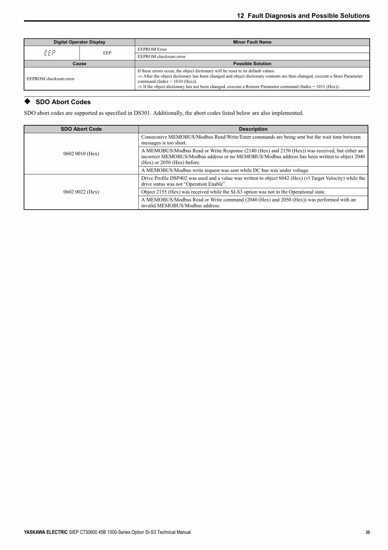
12 Fault Diagnosis and Possible Solutions
YASKAWA ELECTRIC SIEP C730600 45B 1000-Series Option SI-S3 Technical Manual 35
◆ SDO Abort CodesSDO abort codes are supported as specified in DS301. Additionally, the abort codes listed below are also implemented.
Digital Operator Display Minor Fault Name
EEPEEPROM ErrorEEPROM checksum error
Cause Possible Solution
EEPROM checksum error
If these errors occur, the object dictionary will be reset to its default values.⇒ After the object dictionary has been changed and object dictionary contents are then changed, execute a Store Parameter command (Index = 1010 (Hex)).⇒ If the object dictionary has not been changed, execute a Restore Parameter command (Index = 1011 (Hex)).
SDO Abort Code Description
0602 0010 (Hex)
Consecutive MEMOBUS/Modbus Read/Write/Enter commands are being sent but the wait time between messages is too short.A MEMOBUS/Modbus Read or Write Response (2140 (Hex) and 2150 (Hex)) was received, but either an incorrect MEMOBUS/Modbus address or no MEMOBUS/Modbus address has been written to object 2040 (Hex) or 2050 (Hex) before.A MEMOBUS/Modbus write request was sent while DC bus was under voltage.
0602 0022 (Hex)
Drive Profile DSP402 was used and a value was written to object 6042 (Hex) (vl Target Velocity) while the drive status was not “Operation Enable”.Object 2155 (Hex) was received while the SI-S3 option was not in the Operational state.A MEMOBUS/Modbus Read or Write command (2040 (Hex) and 2050 (Hex)) was performed with an invalid MEMOBUS/Modbus address.

36 YASKAWA ELECTRIC SIEP C730600 45B 1000-Series Option SI-S3 Technical Manual
13 Specifications
13 Specifications
◆ SpecificationsTable 10 Option Card Specifications
◆ Revision HistoryThe revision dates and the numbers of the revised manuals appear on the bottom of the back cover.
Items SpecificationsModel SI-S3
Communication Profile DS 301 Ver. 4.02DSP 402 Ver. 1.1 Velocity Mode
Connector 9 pin D-sub connector (#4/40 UNC thread)Communications Speed 10 kbps to 1 MbpsAmbient Temperature –10 °C to +50 °CHumidity up to 95% RH (no condensation)Storage Temperature –20 °C to +60 °C (allowed for short-term transport of the product)Area of Use Indoor (free of corrosive gas, airborne particles, etc.)Altitude up to 1000 m
Date of Publication Revision Number Section Revised Content
December 2010
Front cover Revision: Format
Chapter 4Revision: LED statusDeletion: Node ID Setup
Chapter 6 Revision: Parameter tableChapter 7 Addition: Bit Rate and Node ID Setup
Chapter 8Revision: Object Dictionary descriptionAddition: New object description
Chapter 9 Addition: Configuring Manufacturer Specific ObjectsChapter 10 Addition: Process Data Objects (PDO) and mapping instructionsChapter 11 Addition: Drive Parameter, Monitor and Control Resister Access
Chapter 12 Addition: Fault-PE1SDO Abort Codes
Back cover Revision: Address, formatAugust 2008 − − First Edition
MANUAL NO. SIEP C730600 45APublished in Japan December 2010 08-8
Date of publication
Date of original publication
Revision number1
1

IRUMA BUSINESS CENTER (SOLUTION CENTER)480, Kamifujisawa, Iruma, Saitama 358-8555, JapanPhone 81-4-2962-5151 Fax 81-4-2962-6138
YASKAWA AMERICA, INC.2121 Norman Drive South, Waukegan, IL 60085, U.S.A.Phone (800) YASKAWA (800-927-5292) or 1-847-887-7000 Fax 1-847-887-7310
YASKAWA ELETRICO DO BRASIL LTDA.Avenida Fagundes Filho, 620 Sao Paulo-SP CEP 04304-000, Brazil Phone 55-11-3585-1100 Fax 55-11-5581-8795
YASKAWA EUROPE GmbHHauptstraβe 185, Eschborn 65760, GermanyPhone 49-6196-569-300 Fax 49-6196-569-398
YASKAWA ELECTRIC UK LTD.1 Hunt Hill Orchardton Woods Cumbernauld, G68 9LF, United KingdomPhone 44-1236-735000 Fax 44-1236-458182
YASKAWA ELECTRIC KOREA CORPORATION7F, Doore Bldg. 24, Yeoido-dong, Yeoungdungpo-gu, Seoul 150-877, KoreaPhone 82-2-784-7844 Fax 82-2-784-8495
YASKAWA ELECTRIC (SINGAPORE) PTE. LTD.151 Lorong Chuan, #04-01, New Tech Park 556741, SingaporePhone 65-6282-3003 Fax 65-6289-3003
YASKAWA ELECTRIC (SHANGHAI) CO., LTD.No.18 Xizang Zhong Road. 17F, Harbour Ring Plaza Shanghai 200001, ChinaPhone 86-21-5385-2200 Fax 86-21-5385-3299
YASKAWA ELECTRIC (SHANGHAI) CO., LTD. BEIJING OFFICERoom 1011, Tower W3 Oriental Plaza, No.1 East Chang An Ave.,Dong Cheng District, Beijing 100738, ChinaPhone 86-10-8518-4086 Fax 86-10-8518-4082
YASKAWA ELECTRIC TAIWAN CORPORATION9F, 16, Nanking E. Rd., Sec. 3, Taipei 104, TaiwanPhone 886-2-2502-5003 Fax 886-2-2505-1280
英文 No.9-5 (A4) モーションコントロール事業部用 新CI
In the event that the end user of this product is to be the military and said product is to be employed in any weapons systems or the manufacture thereof, the export will fall under the relevant regulations as stipulated in the Foreign Exchange and Foreign Trade Regulations. Therefore, be sure to follow all procedures and submit all relevant documentation according to any and all rules, regulations and laws that may apply.
Specifications are subject to change without notice for ongoing product modifications and improvements.
© 2008-2010 YASKAWA ELECTRIC CORPORATION. All rights reserved.
Published in Japan December 2010 08-8
MANUAL NO. SIEP C730600 45B
10-10-61 -0
YASKAWA ELECTRIC CORPORATION
CANopenYASKAWA AC Drive 1000-Series Option
Technical Manual