Embed Size (px)
Citation preview

User’s Manual ENGLISH E
YAMAHA SCARA ROBOT
E35-Ver. 1.09
YK-XGYK-X series


Before using the robot(Be sure to read the following notes.)
At this time, our thanks for your purchase of this YAMAHA YK-XG series SCARArobot.
1. Please be sure to perform the following tasks before using the robot.Failing to perform the tasks below will require re-teaching of the robot since theorigin position cannot be set to the same previous position. Robot malfunctions(vibration, noise) may also occur.
The origin position of the YK-XG series robots is adjusted to the robot arm ex-tended position at the factory prior to shipment, so the reference or standard coor-dinates are temporarily set. The customer should set the origin position beforeany other job. There are 2 types of origin position settings as shown below.
[1] Setting the robot arm extended position (the origin position adjustedat the factory prior to shipment) as the origin position(When setting the origin position with the robot arm extended, youmust check that there will not be any interference from any periph-eral equipment during the next absolute reset.)
[2] Setting a position OTHER than the robot arm extended position(the origin position adjusted at the factory prior to shipment) as theorigin position
[1] To set the robot arm extended position (the origin position adjustedat the factory prior to shipment) as the origin position
Absolute ResetThe YK-XG series robots only require the absolute reset to be performed oncewhen the robot is introduced. Once the absolute reset is performed, you do notneed to reperform it when the power is turned on next time. Set the originposition while referring to absolute reset methods in "3. Adjusting the origin"in Chapter 4 of this manual and in "Absolute Reset" of the "YAMAHA RobotController User's Manual". Setting of standard coordinates is not required inthe above case. To set the standard coordinates with high accuracy, refer to "5.Setting the Standard Coordinates" in Chapter 4 of this manual and "Setting theStandard Coordinates" in the "YAMAHA Robot Controller User's Manual". Ifthe standard coordinate settings are incorrect, robot malfunctions (vibration,excessive noise) may occur.
! CAUTION
Never enter the robot movement range once the robot servo is turned on asthis is extremely hazardous.

[2] To set a position OTHER than the robot arm extended position (theorigin position adjusted at the factory prior to shipment) as theorigin position
1. Absolute resetThe YK-XG series robots only require the absolute reset to be performed oncewhen the robot is introduced. Once the absolute reset is performed, you do notneed to reperform it when the power is turned on next time. Set the originposition while referring to absolute reset methods in "3. Adjusting the origin"in Chapter 4 of this manual and in "Absolute Reset" of the "YAMAHA RobotController User's Manual". Set the origin position with the absolute reset.
! CAUTION
Never enter the robot movement range once the robot servo is turned on asthis is extremely hazardous.
2. Affixing the origin position stickerSet in emergency stop when absolute reset is complete, and immediately affixthe origin point sticker according to instructions in "6. Affixing Stickers forOrigin Positions, Movement Directions and Axis Names" in Chapter 4 of thismanual.
3. Setting the reference coordinatesSet the reference coordinates while referring to instructions in "5. Setting theReference Coordinates" in Chapter 4 of this manual and also to "Setting theReference Coordinates" in the "YAMAHA Robot Controller User's Manual".Robot malfunctions (vibration, noise) may occur if the reference coordinatesare not set correctly.
Even though there is no problem with the robot, the following error messages areissued when the robot and controller are connected and power first turned on.(Actual error messages may differ according to how the robot and controller areconnected.)
Error messages issued when robot & controller are connected (RCX240)17.81 : D?.ABS.battery wire breakage17.83 : D?.Backup position data error 117.85 : D?.Backup position data error 217.92 : D?.Resolver disconnected during power off17.93 : D?.Position backup counter overflow
etc.
2. If the X, Y or R axis rotation angle is small.If the X, Y or R axis rotation angle is smaller than 5° so that it always moves inthe same position, an oil film is difficult to be formed on the joint support bear-ing, possibly leading to damage to the bearing. In this type of operation, add amovement so that the joint moves through 90° or more, about 5 times a day.
3. Do not remove the Z-axis upper-end mechanical stopperRemoving or moving the upper-end mechanical stopper attached to the Z-axisspline can damage the Z-axis ball screw. Never remove or move it.

Introduction
The YAMAHA YK-XG series robots are SCARA type industrial robots devel-oped based on years of YAMAHA experience and achievements in the automa-tion field as well as efforts to streamline our in-house manufacturing systems.The YK-XG series robots have a two-joint manipulator consisting of an X-axisarm and a Y-axis arm, and are further equipped with a vertical axis (Z-axis) and arotating axis (R-axis) at the tip of the manipulator. The YK-XG series robots canbe used for a wide range of assembly applications such as installation and inser-tion of various parts, application of sealant, and packing operations.
This instruction manual describes the safety measures, handling, adjustment andmaintenance of YK-XG series robots for correct, safe and effective use. Be sureto read this manual carefully before installing the robot. Even after you have readthis manual, keep it in a safe and convenient place for future reference. Thisinstruction manual should be used with the robot and considered an integral partof it. When the robot is moved, transferred or sold, send this manual to the newuser along with the robot. Be sure to explain to the new user the need to readthrough this manual.
This manual describes the YK500XG, YK600XG, YK600XGH, YK700XG,YK800XG, YK900XG, and YK1000XG. For details on specific operation andprogramming of the robot, refer to the separate "YAMAHA Robot ControllerUser's Manual".
NOTES
• The contents of this manual are subject to change without prior notice.• Information furnished by YAMAHA in this manual is believed to be reliable.
However, if you find any part unclear or inaccurate in this manual, pleasecontact YAMAHA sales office or dealer.
YAMAHA MOTOR CO., LTD.IM Operations

MEMO

CONTENTS
CHAPTER 1 Using the Robot Safely
1 Safety Information ........................................................................................1-1
2 Essential Caution Items ...............................................................................1-2
3 Special Training for Industrial Robot Operation ...........................................1-8
4 Robot Safety Functions................................................................................1-9
5 Safety Measures for the System ................................................................1-10
6 Trial Operation ........................................................................................... 1-11
7 Work Within the Safeguard Enclosure .......................................................1-12
8 Automatic Operation ..................................................................................1-13
9 Adjustment and Inspection.........................................................................1-13
10 Repair and Modification .............................................................................1-13
11 Warranty ....................................................................................................1-14
12 CE Marking ................................................................................................1-16
CHAPTER 2 Functions
1 Robot Manipulator........................................................................................2-1
2 Robot Controller ...........................................................................................2-3
3 Robot Initialization Number List ...................................................................2-4
CHAPTER 3 Installation
1 Robot Installation Conditions .......................................................................3-11-1 Installation environments ........................................................................................... 3-1
1-2 Installation base ........................................................................................................ 3-2
2 Installation ....................................................................................................3-42-1 Unpacking ................................................................................................................. 3-4
2-2 Checking the product ................................................................................................ 3-5
2-3 Moving the robot ........................................................................................................ 3-6
2-3-1 Moving the YK500XG, YK600XG, YK600XGH, YK700XG, YK800XG, YK900XG,
YK1000XG ...................................................................................................................3-6
2-4 Installing the robot ..................................................................................................... 3-8
3 Protective Bonding .......................................................................................3-9
4 Robot Cable Connection ............................................................................ 3-11

5 User Wiring and User Tubing .....................................................................3-12
6 Attaching the End Effector .........................................................................3-166-1 R-axis tolerable moment of inertia and acceleration coefficient .............................. 3-16
6-1-1 Acceleration coefficient vs. moment of inertia (YK500XG) ........................................ 3-17
6-1-2 Acceleration coefficient vs. moment of inertia (YK600XG) ........................................ 3-17
6-1-3 Acceleration coefficient vs. moment of inertia (YK600XGH) ..................................... 3-18
6-1-4 Acceleration coefficient vs. moment of inertia (YK700XG, YK800XG) ...................... 3-18
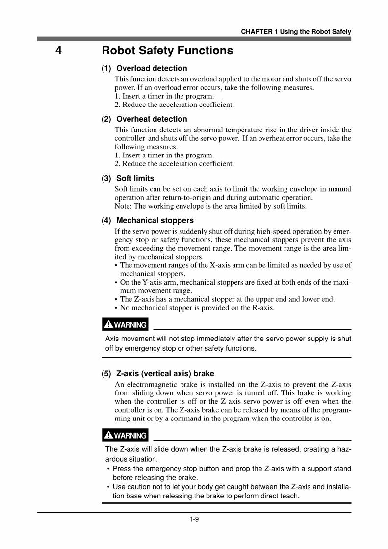
6-1-5 Acceleration coefficient vs. moment of inertia (YK900XG, YK1000XG) .................... 3-19
6-2 Equation for moment of inertia calculation .............................................................. 3-20
6-3 Example of moment of inertia calculation ................................................................ 3-23
6-4 Attaching the end effector ....................................................................................... 3-25
6-5 Gripping force of end effector .................................................................................. 3-29
7 Limiting the Movement Range with X-Axis Mechanical Stoppers ..............3-307-1 YK500XG, YK600XG, YK600XGH, YK700XG, YK800XG, YK900XG, YK1000XG ....... 3-31
8 Working Envelope and Mechanical Stopper Positions for Maximum WorkingEnvelope ....................................................................................................3-33
CHAPTER 4 Adjustment
1 Overview ......................................................................................................4-1
2 Safety Precautions .......................................................................................4-1
3 Adjusting the Origin......................................................................................4-23-1 Absolute reset method .............................................................................................. 4-3
3-1-1 Sensor method (X-axis, Y-axis, and R-axis) ................................................................ 4-3
3-1-2 Stroke end method (Z-axis) ......................................................................................... 4-3
3-2 Machine reference ..................................................................................................... 4-4
3-3 Absolute reset procedures ........................................................................................ 4-5
3-3-1 Sensor method (X-axis, Y-axis, and R-axis) ................................................................ 4-5
3-3-2 Stroke end method (Z-axis) ......................................................................................... 4-7
3-4 Changing the origin position and adjusting the machine reference ........................... 4-8
3-4-1 Sensor method ............................................................................................................4-9
3-4-1-1 YK500XG, YK600XG, YK600XGH, YK700XG, YK800XG, YK900XG, YK1000XG ..... 4-9
3-4-2 Stroke end method .................................................................................................... 4-27
3-4-2-1 YK500XG, YK600XG, YK600XGH, YK700XG, YK800XG, YK900XG, YK1000XG ... 4-27
4 Setting the Soft Limits ................................................................................4-31
5 Setting the Standard Coordinates ..............................................................4-345-1 Standard coordinate setting using a standard coordinate setup jig (option) ........... 4-35
6 Affixing the Stickers for Movement Directions and Axis Names ................4-38

CHAPTER 5 Periodic Inspecition
1 Overview ......................................................................................................5-1
2 Precautions ..................................................................................................5-2
3 Daily Inspection............................................................................................5-3
4 Six-Month Inspection ...................................................................................5-5
5 Replacing the Harmonic Drive .....................................................................5-95-1 Replacement period .................................................................................................. 5-9
5-2 Basic replacement procedure for harmonic drive and precautions ......................... 5-10
5-2-1 YK500XG, YK600XG, YK600XGH, YK700XG, YK800XG, YK900XG, YK1000XG... 5-12
CHAPTER 6 Increasing the robot operating speed
1 Increasing the Robot Operating Speed........................................................6-1
CHAPTER 7 Specifications
1 Manipulator ..................................................................................................7-11-1 Basic specification ..................................................................................................... 7-1
1-2 External view and dimensions ................................................................................... 7-2
1-3 Robot inner wiring diagram ..................................................................................... 7-16
1-4 Wiring table ............................................................................................................. 7-17

MEMO

CHAPTER 1
Using the Robot Safely
1 Safety Information ............................................................................................1-1
2 Essential Caution Items ...................................................................................1-2
3 Special Training for Industrial Robot Operation ...............................................1-8
4 Robot Safety Functions ....................................................................................1-9
5 Safety Measures for the System ....................................................................1-10
6 Trial Operation................................................................................................ 1-11
7 Work Within the Safeguard Enclosure ...........................................................1-12
8 Automatic Operation ......................................................................................1-13
9 Adjustment and Inspection .............................................................................1-13
10 Repair and Modification .................................................................................1-13
11 Warranty .........................................................................................................1-14
12 CE Marking ....................................................................................................1-16

MEMO

1-1
CHAPTER 1 Using the Robot Safely
1 Safety Information
Industrial robots are highly programmable, mechanical devices that provide alarge degree of freedom when performing various manipulative tasks. To ensurecorrect and safe use of YAMAHA industrial robots, carefully read this manualand make yourself well acquainted with the contents. FOLLOW THE WARN-INGS, CAUTIONS AND INSTRUCTIONS INCLUDED IN THIS MANUAL.Failure to take necessary safety measures or mishandling due to not following theinstructions in this manual may result in trouble or damage to the robot and in-jury to personnel (robot operator or service personnel) including fatal accidents.
Warning information in this manual is shown classified into the following items.
DANGER
Failure to follow DANGER instructions will result in severe injury or death to therobot operator, a bystander or a person inspecting or repairing the robot.
WARNINGFailure to follow WARNING instructions could result in severe injury or death tothe robot operator, a bystander or a person inspecting or repairing the robot.
! CAUTIONFailure to follow CAUTION instructions may result in injury to the robot opera-tor, a bystander or a person inspecting or repairing the robot, or damage to therobot and/or robot controller.
NOTE
Explains the key point in the operation in a simple and clear manner.
Refer to the instruction manual by any of the following methods to operate oradjust the robot safely and correctly.
1. Operate or adjust the robot while referring to the printed version of the in-struction manual (available for an additional fee).
2. Operate or adjust the robot while viewing the CD-ROM version of the in-struction manual on your computer screen.
3. Operate or adjust the robot while referring to a printout of the necessarypages from the CD-ROM version of the instruction manual.
It is not possible to detail all safety items within the limited space of this manual.So it is essential that the user have a full knowledge of basic safety rules and alsothat the operator makes correct judgments on safety procedures during operation.This manual and warning labels supplied with or affixed to the robot are writtenin English. If the robot operator or service personnel does not understand Eng-lish, do not permit him to handle the robot.

1-2
CHAPTER 1 Using the Robot Safely
2 Essential Caution ItemsParticularly important cautions for handling or operating the robot are describedbelow. In addition, safety information about installation, operation, inspectionand maintenance is provided in each chapter. Be sure to comply with these in-structions to ensure safe use of the robot.
(1) Observe the following cautions during automatic operation.Warning labels 1 (Fig. 1-1) are affixed to the robot. See Fig. 2-2 for the loca-tions of warning labels.• Install a safeguard enclosure (protective enclosure) to keep any person from
entering within the movement range of the robot and suffering injury dueto being struck by moving parts.
• Install a safety interlock that triggers emergency stop when the door orpanel is opened.
• Install safeguards so that no one can enter inside except from doors orpanels equipped with safety interlocks.
• The warning labels shown in Fig. 1-1 are supplied with the robot and shouldbe affixed to a conspicuous spot on doors or panels equipped with safetyinterlocks.
DANGER
Serious injury or death will result from impact with moving robot.• Keep outside of guard during operation.• Lock out power before approaching robot.
DANGERSerious injury or death will result from impact with moving robot.• Keep outside of guard
during operation.• Lock out power before
approaching robot.
■Fig. 1-1 Warning label 1
(2) Use caution to prevent hands or fingers from being pinched orcrushed.Warning labels 2 (Fig. 1-2) are affixed to the robot. See Fig. 2-2 for the loca-tions of warning labels. Be careful not to let hands or fingers be pinched orcrushed by the moving parts of the robot during transportation or teaching.
WARNING
Moving parts can pinch or crush hands. Keep hands away from robot arms.

1-3
CHAPTER 1 Using the Robot Safely
Moving parts can pinch or crush.Keep hands away from robot arms.
WARNING
■Fig. 1-2 Warning label 2
(3) Follow the instructions on warning labels and in this manual.Warning label 3 (Fig. 1-3) is affixed to the robot. See Fig. 2-2 for the loca-tions of warning labels.• Be sure to read the warning label and this manual carefully and make you
thoroughly understand the contents before attempting installation and op-eration of the robot.
• Before starting the robot operation, even after you have read through thismanual, read again the corresponding procedures and cautions in this manualas well as descriptions in this chapter (Chapter 1, "Using the Robot Safely").
• Never install, adjust, inspect or service the robot in any manner that doesnot comply with the instructions in this manual.
WARNING
Improper installation or operation can result in serious injury or death.Read user's manual and all warning labels before installation or operation.
Improper Installation or operation can result in serious injury or death. Read user's(owner's) manual and all warning labels before operation.
WARNING
■Fig. 1-3 Warning label 3
(4) Do not remove the Z-axis upper-end mechanical stopperRemoving or moving the upper-end mechanical stopper attached to the Z-axis spline can damage the Z-axis ball screw. Never remove or move it.
! CAUTION
Do not remove this part. Damage to the ball screw will result.
■Fig. 1-4 Warning label 4

1-4
CHAPTER 1 Using the Robot Safely
(5) Do not use the robot in environments containing inflammablegas, etc.
WARNING
• This robot was not designed for operation in environments where inflamma-ble or explosive substances are present.
• Do not use the robot in environments containing inflammable gas, dust orliquids. Explosions or fire could otherwise result.
(6) Do not use the robot in locations possibly subject to electro-magnetic interference, etc.
WARNING
Avoid using the robot in locations subject to electromagnetic interference, elec-trostatic discharge or radio frequency interference. Malfunction may otherwiseoccur.
(7) Use caution when releasing the Z-axis (vertical axis) brake.
WARNING
The Z-axis will slide down when the Z-axis brake is released, causing a hazard-ous situation.• Press the emergency stop button and prop up the Z-axis with a support stand
before releasing the brake.• Use caution not to let your body get caught between the Z-axis and installa-
tion base when releasing the brake to perform direct teach.
(8) Provide safety measures for end effector (gripper, etc.).
WARNING
• End effectors must be designed and manufactured so that they cause nohazards (for example, loosening of workpiece) even if power (electricity, airpressure, etc.) is shut off or power fluctuations occur.
• If there is a possible danger that the object gripped by the end effector mayfly off or drop, then provide appropriate safety protection taking into accountthe object size, weight, temperature and chemical properties.

1-5
CHAPTER 1 Using the Robot Safely
(9) Be cautious of possible Z-axis movement when the controller isturned off or emergency stop is triggered. (2-axis robots withair-driven Z-axis)
WARNING
The Z-axis moves up when the power to the controller or PLC is turned off, theprogram is reset, emergency stop is triggered, or air is supplied to the solenoidvalve for the Z-axis air cylinder.• Do not let hands or fingers get caught and squeezed by moving parts of the
Z-axis.• Keep the usual robot position in mind so that the Z-axis will not interfere with
obstacles during raising of the Z-axis, except in case of emergency stop.
(10)Use the following caution items when the Z-axis is interferingwith peripheral equipment. (2-axis robots with air driven Z-axis)
WARNING
When the Z-axis comes to a stop due to obstructions from peripheral equip-ment, the Z-axis may move suddenly when the obstruction is removed, causinginjury such as pinched or crushed hands.• Turn off the controller and reduce the air pressure before attempting to re-
move the obstruction.• Before reducing the air pressure, place a support stand under the Z-axis
because it will drop under its own weight.
(11) Use caution on Z-axis movement when air supply is stopped. (2-axis robots with air-driven Z-axis)
WARNING
The Z-axis may suddenly drop when the air pressure to the Z-axis air cylindersolenoid valve is reduced, creating a hazardous situation.Turn off the controller and place a prop or support under the Z-axis beforecutting off the air supply.
(12)Use the following caution items when disassembling or replac-ing the pneumatic equipment.
WARNING
Air or parts may fly outwards if pneumatic equipment is disassembled or partsreplaced while air is still supplied.• Do service work after first turning off the controller and reducing the air pres-
sure.• Before reducing the air pressure, place a support stand under the Z-axis (2-
axis robots with air driven Z-axis) since it will drop under its own weight.

1-6
CHAPTER 1 Using the Robot Safely
(13)Use the following caution items when removing the Z-axis mo-tor.
WARNING
The Z-axis will drop when the Z-axis motor is removed, possibly resulting ininjury.• Turn off the controller and set a support stand under the Z-axis before re-
moving the motor.• Use caution not to allow hands or body to be squeezed or crushed by moving
parts on the Z-axis or between the Z-axis and the installation base.
(14)Use the following caution during inspection of controller.
WARNING
• When you need to touch the terminals or connectors on the outside of thecontroller during inspection, always first turn off the controller power switchand also the power source in order to prevent possible electrical shock.
• Never touch any internal parts of the controller.
For precautions on handling the controller, refer to the "YAMAHA Robot Con-troller User's Manual".
(15)Consult us for corrective action when the robot is damaged ormalfunction occurs.
WARNING
If any part of the robot is damaged or any malfunction occurs, continuous op-eration may be very dangerous. Please consult YAMAHA dealer for correctiveaction.
If the following damages or troubles exist These dangers can happen
Damage to machine harness or robot cable Electrical shock, malfunction of robot
Damage to exterior of robotFlying outwards of damaged parts during robot
operation
Abnormal operation of robot
(positioning error, excessive vibration, etc.)Malfunction of robot
Z-axis brake trouble Dropping of load
(16)Use caution not to touch the high temperature motor or speedreduction gear casing.
WARNING
The motor and speed reduction gear casing are extremely hot after automaticoperation, so burns may occur if these are touched. Before touching theseparts during inspections or servicing, turn off the controller, wait for a while andcheck that the temperature has cooled.

1-7
CHAPTER 1 Using the Robot Safely
(17)Do not remove, alter or stain the warning labels.
WARNING
If warning labels are removed or difficult to see, necessary cautions may not betaken, resulting in an accident.• Do not remove, alter or stain the warning labels on the robot.• Do not allow the warning labels to be hidden by the device installed to the
robot by the user.• Provide proper lighting so that the symbols and instructions on the warning
labels can be clearly seen even from the outside of safeguard enclosure.
(18)Protective bonding
WARNING
Be sure to ground the robot and controller to prevent electrical shock.
(19)Be sure to make correct parameter settings.
! CAUTION
The robot must be operated with correct tolerable moment of inertia and accel-eration coefficients according to the manipulator tip mass and moment of iner-tia. If this is not observed, premature end to the life of the drive units, damage tothe robot parts or residual vibration during positioning may result.
(20)Do not use the robot for tasks requiring motor thrust.
! CAUTION
Avoid using the YK-XG series robots for tasks which make use of motor thrust(press-fitting, burr removal, etc.). These tasks may cause malfunctions of therobot.
(21) If the X, Y or R axis rotation angle is small
! CAUTION
If the X, Y or R axis rotation angle is smaller than 5° so that it always moves inthe same position, an oil film is difficult to be formed on the joint support bear-ing, possibly leading to damage to the bearing. In this type of operation, add amovement so that the joint moves through 90° or more, about 5 times a day.

1-8
CHAPTER 1 Using the Robot Safely
3 Special Training for Industrial Robot Opera-tion
Companies or factories using industrial robots must make sure that every person,who handles the robot such as for teaching, programming, movement check, in-spection, adjustment and repair, has received appropriate training and also hasthe skills needed to perform the job correctly and safely.Since the YK-XG series robots fall under the industrial robot category, the usermust observe local regulations and safety standards for industrial robots, andprovide special training for every person involved in robot-related tasks (teach-ing, programming, movement check, inspection, adjustment, repair, etc.).
1-9
CHAPTER 1 Using the Robot Safely
4 Robot Safety Functions(1) Overload detection
This function detects an overload applied to the motor and shuts off the servopower. If an overload error occurs, take the following measures.1. Insert a timer in the program.2. Reduce the acceleration coefficient.
(2) Overheat detectionThis function detects an abnormal temperature rise in the driver inside thecontroller and shuts off the servo power. If an overheat error occurs, take thefollowing measures.1. Insert a timer in the program.2. Reduce the acceleration coefficient.
(3) Soft limitsSoft limits can be set on each axis to limit the working envelope in manualoperation after return-to-origin and during automatic operation.Note: The working envelope is the area limited by soft limits.
(4) Mechanical stoppersIf the servo power is suddenly shut off during high-speed operation by emer-gency stop or safety functions, these mechanical stoppers prevent the axisfrom exceeding the movement range. The movement range is the area lim-ited by mechanical stoppers.• The movement ranges of the X-axis arm can be limited as needed by use of
mechanical stoppers.• On the Y-axis arm, mechanical stoppers are fixed at both ends of the maxi-
mum movement range.• The Z-axis has a mechanical stopper at the upper end and lower end.• No mechanical stopper is provided on the R-axis.
WARNING
Axis movement will not stop immediately after the servo power supply is shutoff by emergency stop or other safety functions.
(5) Z-axis (vertical axis) brakeAn electromagnetic brake is installed on the Z-axis to prevent the Z-axisfrom sliding down when servo power is turned off. This brake is workingwhen the controller is off or the Z-axis servo power is off even when thecontroller is on. The Z-axis brake can be released by means of the program-ming unit or by a command in the program when the controller is on.
WARNING
The Z-axis will slide down when the Z-axis brake is released, creating a haz-ardous situation.• Press the emergency stop button and prop the Z-axis with a support stand
before releasing the brake.• Use caution not to let your body get caught between the Z-axis and installa-
tion base when releasing the brake to perform direct teach.

1-10
CHAPTER 1 Using the Robot Safely
5 Safety Measures for the System
Since the robot is commonly used in conjunction with an automated system, dan-gerous situations are more likely to occur from the automated system than fromthe robot itself. Accordingly, appropriate safety measures must be taken on thepart of the system manufacturer according to the individual system. The systemmanufacturer should provide a proper instruction manual for safe, correct opera-tion and servicing of the system.

1-11
CHAPTER 1 Using the Robot Safely
6 Trial Operation
After making installations, adjustments, inspections, maintenance or repairs tothe robot, make a trial run using the following procedures.
(1) If a safeguard enclosure has not yet been provided right after installation ofthe robot, rope off or chain off around the movement area of the manipulatorin place of the safeguard enclosure, and observe the following points.1. Use sturdy, stable posts which will not fall over easily.2. The rope or chain should be easily visible by everyone around the robot.3. Place a sign to keep the operator or other personnel from entering the
movement range of the manipulator.(2) Check the following points before turning on the controller.
1. Is the robot securely and correctly installed?2. Are the electrical connections to the robot correct?3. Are items such as air pressure correctly supplied?4. Is the robot correctly connected to peripheral equipment?5. Have safety measures (safeguard enclosure, etc.) been taken?6. Does the installation environment meet the specified standards?
(3) After the controller is turned on, check the following points from outside thesafeguard enclosure.1. Does the robot start and stop as intended? Can the operation mode be
selected correctly?2. Does each axis move as intended within the soft limits?3. Does the end effector move as intended?4. Are the signal transmissions to the end effector and peripheral equipment
correct?5. Does emergency stop work?6. Are the teaching and playback functions normal?7. Are the safeguard enclosure and interlock working as intended?8. Does the robot move correctly during automatic operation?

1-12
CHAPTER 1 Using the Robot Safely
7 Work Within the Safeguard Enclosure
(1) When work is required inside the safeguard enclosure, always turn off thecontroller and place a sign indicating that the robot is being adjusted or serv-iced in order to keep any other person from touching the controller switch oroperation panel, except for the following cases.1) Origin position setting (See Section 3 in Chapter 4.)2) Soft limit settings (See Section 4 in Chapter 4.)3) Standard coordinate settings (See Section 5 in Chapter 4.)4) Teaching
For items 1) to 3), follow the precautions and procedure for each section. Toperform item 4), refer to the description in (2) below.
(2) TeachingWhen performing teaching within the safeguard enclosure, comply with theinstructions listed below.1) Check or perform the following points from outside the safeguard enclo-
sure.1. Make sure that no hazards are present within the safeguard enclosure
by a visual check.2. Check that the programming unit MPB operates correctly.3. Check that no failures are found in the robot.4. Check that emergency stop works correctly.5. Select teaching mode and prohibit automatic operation.
2) Never enter the movement range of the manipulator while within the safe-guard enclosure.

1-13
CHAPTER 1 Using the Robot Safely
8 Automatic Operation
Automatic operation described here includes all operations in AUTO mode.
(1) Check the following before starting automatic operation.1. No one is within the safeguard enclosure.2. The programming unit and tools are in their specified locations.3. The alarm or error lamps on the robot and peripheral equipment do not
flash.4. The safeguard enclosure is securely installed with safety interlocks ac-
tuated.(2) Observe the following during automatic operation or in cases where an error
occurs.1) After automatic operation has started, check the operation status and warn-
ing lamp to ensure that the robot is in automatic operation.2) Never enter the safeguard enclosure during automatic operation.3) If an error occurs in the robot or peripheral equipment, observe the fol-
lowing procedure before entering the safeguard enclosure.1. Press the emergency stop button to set the robot to emergency stop.2. Place a sign on the start switch, indicating that the robot is being in-
spected in order to keep any other person from touching the start switchand restarting the robot.
9 Adjustment and Inspection
Do not attempt any installation, adjustment, inspection or maintenance unless itis described in this manual.
10 Repair and Modification
Do not attempt any repair, parts replacement and modification unless describedin this manual. These works require technical knowledge and skill, and may alsoinvolve work hazards.

1-14
CHAPTER 1 Using the Robot Safely
11 Warranty
The YAMAHA robot and/or related product you have purchased are warrantedagainst the defects or malfunctions as described below.
Warranty description : If a failure or breakdown occurs due to defectsin materials or workmanship in the genuineparts constituting this YAMAHA robot and/orrelated product within the warranty period, thenYAMAHA will repair or replace those parts freeof charge (hereafter called "warranty repair").
Warranty Period : The warranty period ends when any of the fol-lowing applies:(1) After 18 months (one and a half year) have
elapsed from the date of shipment(2) After one year has elapsed from the date of
installation(3) After 2,400 hours of operation
Exceptions to the Warranty : This warranty will not apply in the followingcases:(1) Fatigue arising due to the passage of time,
natural wear and tear occurring during op-eration (natural fading of painted or platedsurfaces, deterioration of parts subject towear, etc.)
(2) Minor natural phenomena that do not affectthe capabilities of the robot and/or relatedproduct (noise from computers, motors,etc.).
(3) Programs, point data and other internal datathat were changed or created by the user.
Failures resulting from the following causes are not covered by warranty repair.
1) Damage due to earthquakes, storms, floods, thunderbolt, fire or any othernatural or man-made disasters.
2) Troubles caused by procedures prohibited in this manual.
3) Modifications to the robot and/or related product not approved byYAMAHA or YAMAHA sales representatives.
4) Use of any other than genuine parts and specified grease and lubricants.
5) Incorrect or inadequate maintenance and inspection.
6) Repairs by other than authorized dealers.

1-15
CHAPTER 1 Using the Robot Safely
YAMAHA MOTOR CO., LTD. MAKES NO OTHER EXPRESS OR IMPLIEDWARRANTIES, INCLUDING ANY IMPLIED WARRANTY OFMERCHANTABILITY OR FITNESS FOR ANY PARTICULAR PURPOSE.THE WARRANTY SET FORTH ABOVE IS EXCLUSIVE AND IS IN LIEUOF ALL EXPRESSED OR IMPLIED WARRANTIES, INCLUDING WARRAN-TIES OF MERCHANTABILITY, FITNESS FOR A PARTICULAR PURPOSE,OR WARRANTIES ARISING FROM A COURSE OF DEALING OR USAGEOF TRADE.YAMAHA MOTOR CO., LTD. SOLE LIABILITY SHALL BE FOR THE DE-LIVERY OF THE EQUIPMENT AND YAMAHA MOTOR CO., LTD. SHALLNOT BE LIABLE FOR ANY CONSEQUENTIAL DAMAGES (WHETHERARISING FROM CONTRACT, WARRANTY, NEGLIGENCE OR STRICTLIABILITY). YAMAHA MOTOR CO., LTD. MAKES NO WARRANTY WHAT-SOEVER WITH REGARD TO ACCESSORIES OR PARTS NOT SUPPLIEDBY YAMAHA MOTOR CO., LTD.

1-16
CHAPTER 1 Using the Robot Safely
12 CE Marking
When the YAMAHA robots are exported to or used in EU (European Union)countries, refer to the separate "YAMAHA Robot Controller User's Manual" or"CE marking manual" for related information about CE marking.

CHAPTER 2
Functions
1 Robot Manipulator ............................................................................................2-1
2 Robot Controller ...............................................................................................2-3
3 Robot Initialization Number List .......................................................................2-4

MEMO

2-1
CHAPTER 2 Functions
1 Robot Manipulator
The YK-XG series robots are available in 4-axis models having an X/Y-axis arm(equivalent to human arm) and a Z/R-axis (equivalent to human wrist). With these4 axes, the YK-XG series robots can move as shown in Fig. 2-1. By attachingdifferent types of end effector (gripper) to the end of the arm, a wide range oftasks can be performed with high precision at high speeds. The (+) and (-) signsshow the direction of axis movement when the jog keys on the programming unitare pressed (standard setting at the factory). Fig. 2-2 on the subsequent pagesshow part names and functions of each robot model.
Y-axis arm
Y-axis(+)
(-)
X-axis arm
(+)Z-axis
X-axis
(-)
(-)
(+)
(+)R-axis
(-)
Fig. 2-1 Manipulator movement

CHAPTER 2 Functions
2-2
User tubing 1 (φ6 black)
User tubing 2 (φ6 red)
User tubing 3 (φ6 blue)
Machine harness
Eyebolt installation position
D-sub connector for user wiring (No.1 to 20)
Ball screw
R-axis motor
R-axis speed reduction gear
End effector attachment
Z-axis spline
Z-axis motor
Y-axis speed reduction gear
Y-axis arm
Y-axis motor
X-axis arm
Y-axis mechanical stopper
Warning label 3
X-axis motor
Tapped hole and screw for user
X-axis speed reduction gear
X-axis movable mechanical stopper
Warning label 1Warning label 2 on opposite side
User tubing 1 (φ6 black)
User tubing 2 (φ6 red)User tubing 3 (φ6 blue)
M4 ground terminal
Robot cable
D-sub connector for user wiring (No.1 to 20)
Serial labelWarning label 4
Fig. 2-2 YK500XG, YK600XG, YK600XGH, YK700XG, YK800XG, YK900XG, YK1000XG

2-3
CHAPTER 2 Functions
2 Robot Controller
The YK-XG series robot comes supplied with a robot controller RCX240. Formore details, refer to the separate "YAMAHA Robot Controller User's Manual".
RPB
MOTOR
XM
YM
ZM
RM
PWR
SRV
SAFETY
RPB
COM
STD.DIO
ROBI/O
ZR
OP.1 OP.3
OP.2 OP.4RGEN
ACIN
N
P
N1
L1
L
N
SEL
BATTZR
XYBATT
ROB
XY
I/O
13 14EXT.E-STOP
ERR
RCX240
RCX240
Fig. 2-3 Robot controller

CHAPTER 2 Functions
2-4
3 Robot Initialization Number List
The YK-XG series robots are initialized for optimum setting (default setting)according to the robot model prior to shipping. The robot controllers do not haveto be reinitialized during normal operation. However, if for some reason the con-troller must be reinitialized, proceed while referring to the list below.
! CAUTION
• Absolute reset must be performed after reinitializing the controller.Before reinitializing the controller, read the descriptions in "3. Adjusting theorigin" in Chapter 4 and make sure you thoroughly understand the proce-dure.
• When the controller is initialized, the "ARM LENGTH" and "OFFSET PULSE"settings in the axis parameters will be erased, making the standard coordi-nate settings invalid. (For details on standard coordinates, see "5. Settingthe Standard Coordinates" in Chapter 4.) If you do not want to change theorigin position by initializing, make a note of the "ARM LENGTH" and "OFF-SET PULSE" settings before initializing, and re-enter their settings after ini-tialization is complete.
Robot initialization number
2117
2118
2119
2120
2121
2122
2123
2124
2125
2126
2127
2128
2129
2130
Model name
YK500XG Z200
YK500XG Z300
YK600XG Z200
YK600XG Z300
YK600XGH Z200
YK600XGH Z400
YK700XG Z200
YK700XG Z400
YK800XG Z200
YK800XG Z400
YK900XG Z200
YK900XG Z400
YK1000XG Z200
YK1000XG Z400

CHAPTER 3
Installation
1 Robot Installation Conditions ...........................................................................3-11-1 Installation environments ................................................................................................ 3-1
1-2 Installation base.............................................................................................................. 3-2
2 Installation ........................................................................................................3-42-1 Unpacking....................................................................................................................... 3-4
2-2 Checking the product ...................................................................................................... 3-5
2-3 Moving the robot ............................................................................................................. 3-6
2-3-1 Moving the YK500XG, YK600XG, YK600XGH, YK700XG, YK800XG, YK900XG,
YK1000XG ........................................................................................................................ 3-6
2-4 Installing the robot .......................................................................................................... 3-8
3 Protective Bonding ...........................................................................................3-9
4 Robot Cable Connection ................................................................................ 3-11
5 User Wiring and User Tubing .........................................................................3-12
6 Attaching the End Effector .............................................................................3-166-1 R-axis tolerable moment of inertia and acceleration coefficient ................................... 3-16
6-1-1 Acceleration coefficient vs. moment of inertia (YK500XG) .............................................. 3-17
6-1-2 Acceleration coefficient vs. moment of inertia (YK600XG) .............................................. 3-17
6-1-3 Acceleration coefficient vs. moment of inertia (YK600XGH) ........................................... 3-18
6-1-4 Acceleration coefficient vs. moment of inertia (YK700XG, YK800XG) ............................ 3-18
6-1-5 Acceleration coefficient vs. moment of inertia (YK900XG, YK1000XG) .......................... 3-19
6-2 Equation for moment of inertia calculation ................................................................... 3-20
6-3 Example of moment of inertia calculation ..................................................................... 3-23
6-4 Attaching the end effector ............................................................................................. 3-25
6-5 Gripping force of end effector ....................................................................................... 3-29
7 Limiting the Movement Range with X-Axis Mechanical Stoppers ..................3-307-1 YK500XG, YK600XG, YK600XGH, YK700XG, YK800XG, YK900XG, YK1000XG ..... 3-31
8 Working Envelope and Mechanical Stopper Positions for Maximum WorkingEnvelope ........................................................................................................3-33

MEMO

3-1
CHAPTER 3 Installation
1 Robot Installation Conditions
1-1 Installation environments
Be sure to install the robot in the following environments.
Setting environments
Allowable ambient temperature
Allowable ambient humidity
Altitude
Ambient environments
Vibration
Air supply pressure, etc.
Working space
Specifications
0 to 40°C
35 to 85% RH (non condensation)
0 to 1000 meters above sea level
Avoid installing near water, cutting water, oil, dust, metallic chips and organic solvent.
Avoid installation near corrosive gas and corrosive materials.
Avoid installation in atmosphere containing inflammable gas, dust or liquid.
Avoid installation near objects causing electromagnetic interference, electrostatic discharge or radio frequency interference.
Do not subject to impacts or vibrations.
Below 0.58MPa (6.0kgf/cm2); clean dry air not containing deteriorated compressor oil; filtration 40µm or less
Allow sufficient space margin to perform jobs (teaching, inspection, repair, etc.)
For detailed information on how to install the robot controller, refer to the sepa-rate "YAMAHA Robot Controller User's Manual".
WARNING
• Avoid installing the robot in locations where the ambient conditions may ex-ceed the allowable temperature or humidity, or in environments where water,corrosive gases, metallic powder or dust are generated. Malfunction, failureor short circuits may otherwise result.
• This robot was not designed for operation in environments where inflamma-ble or explosive substances are present. Do not use the robot in environ-ments containing inflammable gas, dust or liquids. Explosions or fire couldotherwise result.
• Avoid using the robot in locations subject to electromagnetic interference,electrostatic discharge or radio frequency interference. Malfunction may oth-erwise occur.
• Do not use the robot in locations subject to excessive vibration. Robot instal-lation bolts may otherwise become loose causing the manipulator to fall over.

3-2
CHAPTER 3 Installation
1-2 Installation base
WARNING
• Install the robot on a horizontal surface, with the base mount section facingdown. If installed by other methods with the base mount section not facingdown, grease might leak from the reduction gear unit.
• Do not place the robot on a moving installation base. Excessive loads will beapplied to the robot arm by movement of the installation base, resulting indamage to the robot.
! CAUTION
• The manipulator positioning might decrease if the installation surface preci-sion is insufficient.
• If the installation base is not sufficiently rigid and stable or a thin metallicplate is attached to the installation base, vibration (resonance) may occurduring operation, causing detrimental effects on the manipulator work.
1) Prepare a sufficiently rigid and stable installation base, taking account of therobot weight including the end effector (gripper), workpiece and reactionforce while the robot is operating. The maximum reaction force (see Fig. 3-1) applied to the X-axis and Z-axis of each robot during operation is shownin the table below. These values are an instantaneous force applied to therobot during operation and do not indicate the maximum load capacity.
Robot Model
YK500XG
YK600XG
YK600XGH
YK700XG
YK800XG
YK900XG
YK1000XG
FXmax MXmax FZmax
The maximum reaction force
N kgf Nm kgfm N kgf
1416 144 178 18 134 14
1476 150 178 18 134 14
2125 217 395 40 205 21
2479 253 395 40 239 24
2561 261 395 40 239 24
2494 254 395 40 165 17
2427 248 395 40 165 17

3-3
CHAPTER 3 Installation
Fxmax
Fzmax
Mxmax
Load
Fig. 3-1 Maximum reaction force applied during operation
2) The parallelism of the installation base surface must be machined within aprecision of ±0.05mm/500mm. The robot base mount must be installed fac-ing down and in a level position (except ceiling-mount models which shouldbe installed with the base mount facing up).
3) Tap holes into the surface of the installation base. For machining dimensionsand positions, refer to “1-2 External view and dimensions” in Chapter 7.
4) Securely fix the installation base on the floor with anchor bolts.

3-4
CHAPTER 3 Installation
2 Installation
2-1 Unpacking
WARNING
The robot and controller are heavy. Take sufficient care not to drop them duringmoving or unpacking as this may damage the equipment or cause bodily injury.
! CAUTION
When moving the robot or controller by equipment such as a folklift that requirea license, only properly qualified personnel may operate it. The equipment andtools used for moving the robot should be serviced daily.
The YK-XG series robot comes packed with a robot controller and accessories,according to the order specifications. Using a carrying cart (dolly) or forklift,move the package to near the installation base. Take sufficient care not to applyshocks to the equipment when unpacking it.
YK500XG, YK600XG, YK600XGH, YK700XG, YK800XG, YK900XG, YK1000XG
Robot manipulator
Robot controller and accessories
Arm clamping stay(Used only for transportation.
Remove after installation.)
Fig. 3-2 Packed state

3-5
CHAPTER 3 Installation
2-2 Checking the product
After unpacking, check the product configuration and conditions.The following configurations are typical examples, so please check that the prod-uct is as specified in your order.
! CAUTION
If there is any damage due to transportation or insufficient parts, please notifyyour YAMAHA sales office or dealer immediately.
Controller : RCX240Robot : YK500XG, YK600XG, YK600XGH, YK700XG, YK800XG,
YK900XG, YK1000XG
A BX YZ R
RPBMOTOR
XM
YM
ZM
RM
PWR
SRV
SAFETY
RPB
COM
STD.DIO
ROBI/O
ZR
OP.1OP.3
OP.2OP.4
ACINN
P
N1
L1
L
N
SEL
BATT
ZR
XYBATT
ROB
XY
I/O
13 14EXT.E-STOP
ERR
RCX240 Robot manipulatorYK-XG series
CD-ROM User's Manualor
User's Manual
RCX240controller
Warning label ( × 1)
Standard coordinate setting jig (option)
Eyebolts( × 2)
Origin position stickers
D-sub connector/hood ( × 2)
Standard
Option
RPB programming box, etc.
Fig. 3-3 Product configurations

3-6
CHAPTER 3 Installation
2-3 Moving the robot
WARNING
Serious injury may occur if the robot falls and pins someone under it.• Do not allow any part of your body to enter the area beneath the robot during
work.• Always wear a helmet, safety shoes and gloves during work.
To check the mass of each robot, refer to "1-1 Basic specifications" in Chapter 7.
2-3-1 Moving the YK500XG, YK600XG, YK600XGH, YK700XG,YK800XG, YK900XG, YK1000XG
WARNING
Serious injury may occur if the robot falls and pins someone under it.• Check that there are no cracks and corrosion on the eyebolt installation. If
found, do not use eyebolts to move the robot.• Screw the eyebolts securely into the tapped holes until the bearing surface of
eyebolt makes tight contact with the bearing surface on the arm.• Use a hoist and rope with carrying capacity strong enough to support the
robot weight.• Make sure the rope stays securely on the hoist hook.• Remove all loads attached to the robot manipulator end. If any load is still
attached, the robot may lose balance while being carried, and topple overcausing accidents.
! CAUTION
• When moving the robot by equipment such as cranes that require a license,only properly qualified personnel may operate it.
• The equipment and tools used for moving the robot should be serviced daily.
To move a robot (for example, the YK500XG) correctly and safely, follow theprocedure below. (See Fig. 3-4.) Use the same procedure to move other robots.
1) Lower the Z-axis to a point approximately 24mm (35mm for YK600XGH orlonger arm robots) lower than the origin position. Then turn off the controllerand unplug the robot cable from the controller. (The Z-axis is fixed to thebase with an arm clamp stay at the factory prior to shipment.)
2) Remove the bolts on the X-axis arm.3) Fold the X and Y-axis arms as shown in the drawing, and clamp the Y axis
arm to the robot base by using the stay, bolts and washers (2 washers forYK500XG and YK600XG; 1 washer for YK600XGH or longer arm robots)that come with the robot.If the arms cannot be folded in the carrying position due to the X-axismechanical stoppers, then remove them. (When the robot is shipped, themechanical stoppers are installed to provide the maximum movement range.)

3-7
CHAPTER 3 Installation
4) Screw the two eyebolts through washers into the upper surface of the X-axis arm.5) Wind the robot cable around the upper part of the robot base so that it does
not hang up on the base mount, then fasten the cable end with adhesive tape.6) Prepare two looped ropes with the same length to allow a good lifting balance,
then pass each rope through each eyebolt and catch it on the hoist hook.7) Slightly lift the hoist so that each rope has light tension to hold the robot. In
this state, remove the bolts securing the robot base to the pallet supplied orinstallation base (if robot is to be moved to another installation base).
8) Using caution to keep the balance of the robot and avoid subjecting it to anystrong vibrations and shocks, operate the hoist carefully to move to theinstallation base. The angle between each rope and the arm surface should bekept at 45 degrees or more.
9) Slightly lower the robot on the installation base and temporarily secure it bytightening the bolts.(For tightening torque to secure the robot firmly, see the next section, "2-4Installing the robot".)
10) Remove the rope, eyebolts and arm clamp stay. Screw the bolts into the uppersurface of the X-axis. (Always attach these bolts to protect the eyebolt holethreads.) Be sure to keep the eyebolts, arm clamp stay, bolts and pallet, sincethey may be used to move the robot again.
Pallet (supplied with the robot)
Screw, or bolt and nut (4 pieces supplied)
Bolt
Bolt M16×25 (supplied with YK500XG, YK600XG)Bolt M20×25 (supplied with YK600XGH or longer arm robots)Tightening torque 71Nm (720kgfcm)
Arm clamp stay (supplied)
Bolts (M4×8) 2 pieces (supplied)Tightening torque 4.5Nm (46kgfcm)
45° or more
Washers (under stay)
Hoist hook
Rope
Eyebolt
Washer
Fig. 3-4

3-8
CHAPTER 3 Installation
2-4 Installing the robot
Install the robot securely with the four hex socket head bolts as shown in Fig. 3-5.
WARNING
When installing the robot, be sure to use the specified size and quantity of boltsthat match the depth of tapped holes in the installation base, and securelytighten the bolts to the correct torque. If the bolts are not tightened correctly, therobot might fall over during operation causing a serious accident.
Robot Model
YK500XG, YK600XG
YK600XGH, YK700XG, YK800XG, YK900XG, YK1000XG
M10
M12
71Nm (720kgfcm)
128Nm (1310kgfcm)
Bolts Used Tightening torque
Tightening torque
Depth of tapped holes in installation base:Iron installation base Bolt diameter × 1.5 or moreAluminum installation base Bolt diameter × 3 or moreRecommended bolt JIS B 1176 hex socket head bolt, or equivalent
Strength class JIS B 1051 12.9, or equivalent
Installation base
Hex socket head bolt
Fig. 3-5 Installing the robot

3-9
CHAPTER 3 Installation
3 Protective Bonding
WARNING
• Be sure to ground the robot and controller to prevent electrical shock.• Turn off the controller before grounding the robot.
The robot must be grounded as follows:1) Provide a terminal marked "PE" for the protective conductor of the entire
system and connect it to an external protective conductor. In addition, se-curely connect the ground terminal on the robot pedestal to the same protec-tive conductor. (See Fig. 3-6 for example of the YK500XG.)
(Symbol 417-IEC-5019)
2) When the end effector uses an electrical device which, if it malfunctions,might make contact with the power supply, the user must provide propergrounding on his own responsibility. The YK-XG series robots do not have aground terminal for this purpose.
3) For details on protective bonding on the robot body to comply with CE Mark-ing, follow the instructions on protective bonding explained in the "YAMAHARobot Controller User's Manual" or "CE Marking manual".
4) Use a ground cable with a conductor wire cross section of at least 2.0mm2
and a length within 1 meter.

3-10
CHAPTER 3 Installation
Ground symbol
M4 Ground terminal
Fig. 3-6 Ground terminal

3-11
CHAPTER 3 Installation
4 Robot Cable Connection
The robot cable is pre-connected to the YK-XG series robot. For details on con-nections to the robot controller, refer to Fig. 3-7 and the "YAMAHA Robot Con-troller User's Manual". After making connections, check the operation while re-ferring to "6 Trial operation" in Chapter 1.
WARNING
• Before connecting the cables, check that there are no bends or breaks in theconnector pins of the robot cable and that the cables are not damaged. Bentor broken pins or cable damage may cause malfunction of the robot.
• Ensure that the controller is off before connecting the robot cable to the con-troller.
• In the RCX240 controller, the MOTOR connectors XM and ZM, and YM andRM each have identical shapes. In addition, the PI connectors XY and ZRhave identical shapes. Do not confuse these connectors when making con-nections. Wrong connections may result in malfunction and hazardous situa-tions.
• If the connector installation is inadequate or if there are contact failures in thepins, the robot may malfunction causing a hazardous situation. Reconfirmthat each connector is securely installed before turning on the controller.
• To attach the PI connector securely, tighten the screws supplied with therobot.
• Take caution not to apply an excessive load to the connectors due to stressor tension on the cables.
• Lay out the cables so that they do not obstruct the movement of the manipu-lator. Determine the robot work area in which the robot cables will not inter-fere with the load or workpiece picked up by the manipulator. If the robotcables interfere with the movable parts of the robot, the cables may be dam-aged causing malfunction and hazardous situations. Refer to “1-2 Externalview and dimensions” in Chapter 7.
• Lay out the robot cables so as to keep the operator or any other person fromtripping on them. Bodily injury may result if someone trips on the cables.
Robot cable
Controller side connector
Robot side connector RCX240
XM
YM
ZM
RM
ROB I/O
XY
ROB I/O
ZR
XM
YM
ZM
RM
XY
ZR
Fig. 3-7 Robot cable connections

3-12
CHAPTER 3 Installation
5 User Wiring and User Tubing
WARNING
Always turn off the controller and shut off air supply before attempting wiringand piping work. If air or power is supplied during this work, the manipulatormay move erroneously causing a hazardous situation.
1) The YK-XG series robots are equipped with user wires and air tubes in themachine harness. The table below shows the number of wires and air tubesavailable for each robot model.
Robot model
YK500XG, YK600XG, YK600XGH, YK700XG, YK800XG, YK900XG, YK1000XG
User wiring
20 wires
User tubing
φ6, 3 tubes
(Robot models for custom specifications may have different wiring or tub-ing.)The specifications of the user wires and air tubes are shown below. Alwaysobserve the specifications.
30V
1.5A
0.2mm2
Yes
User Wiring
Rated voltage
Allowable current
Nominal cross-section area of conductor
Shield
User Tubing
Maximum pressure
Outer diameter × inner diameter
Fluid
0.58MPa (6Kgf/cm2)
φ6mm×φ4mm
Dry clean air not containing deteriorated compressor oil; filtration 40µm or less
2) A D-sub connector for user wiring and a bulkhead union for user tubing areprovided one each on the arm side and pedestal side. For the locations, referto “1-2 External view and dimensions” in Chapter 7.

3-13
CHAPTER 3 Installation
3) Signal wiring connections in the machine harness
1. YK500XG, YK600XGConnector pins 1 to 20 can be used. Pin 25 is connected to a shield wireand cannot be used as a signal wire.
NO
1
2
3
4
5
6
7
8
9
10
11
12
13
14
15
16
17
18
19
20
21
22
23
24
25
Signal
User signal line
Shield
Flame Ground
NO
1
2
3
4
5
6
7
8
9
10
11
12
13
14
15
16
17
18
19
20
21
22
23
24
25
1
Connector
I O(Arm side)
Connection Connector
I O(Base side)
FG
Color
Brown
Red
Orange
Blue
Violet
Grey
White
Black
Brown
Red
Orange
Blue
Brown
Red
Orange
Blue
Violet
Grey
White
Black
Green
Green
(Robots models with non-standard specificationsmay have different wiring colors.)

3-14
CHAPTER 3 Installation
4) As shown in Fig. 3-8, solder the user cable wires to the D-sub connector(supplied with the robot). Reattach the hood to the D-sub connector aftersoldering, then plug it into the user wiring connector.The connector pinouts as viewed from the solder side are shown below.
Cable to be prepared by user
SolderingHood
D-sub connector
D-sub connector on arm side(As viewed from solder side)
D-sub connector on base side(As viewed from solder side)
13 12 11 10 9 8 7 6 5 4 3 2 1
25 24 23 22 21 20 19 18 17 16 15 14
1 2 3 4 5 6 7 8 9 10 11 12 13
14 15 16 17 18 19 20 21 22 23 24 25
YK500XG, YK600XG, YK600XGH, YK700XG, YK800XG, YK900XG, YK1000XG
Fig. 3-8
WARNING
• The user cable wires should have a shield wire. Connect it to the same No.pin in the D-sub connector on the robot side, which also connects to theshield wire. If this task is omitted, noise may cause malfunction of the robot.
• Securely attach the D-sub connector (supplied with the robot) into the D-subconnector on the robot side, by tightening the screws on the connector hood.If this connector comes loose or comes off, malfunction may result.
• Avoid fastening the user cable or tube with the machine harness, as this maylead to harness breakage and malfunction.
• Make sure that the user cable attached to the D-sub connector for user wir-ing and the tube attached to the bulkhead union for user tubing will not inter-fere with the robot movement, entangle around the robot or flap around dur-ing operation. Wiring and tubing might then be damaged causing malfunc-tion of the robot.
• Lay out the user cable attached to the D-sub connector for user wiring andthe tube attached to the bulkhead union for user tubing so that they do notobstruct the movement of the operator or any other persons. Bodily injurymay result if anyone trips on the cable or air tube.

3-15
CHAPTER 3 Installation
! CAUTION
• The D-sub connector supplied with the robot should be connected to the armside by pin contact, and to the pedestal side by socket contact. Use cautionat these points when soldering.
• Be sure to use the D-sub connector and hood which are supplied with therobot. Using other types may result in contact failure.
DB-C2-J9RDB-25S-NRDB-25P-NRYK500XG, YK600XG, YK600XGH, YK700XG, YK800XG, YK900XG, YK1000XG
Robot model D-sub connector on arm side D-sub connector on base side Hood
Manufacturer : Japan Aviation Electronics Industry, Limited.
D-sub connectors (supplied with robot)
5) To check the operation and signal transmission between the end effector andthe controller or peripheral equipment after making connections, refer to "6.Trial operation" in Chapter 1.

3-16
CHAPTER 3 Installation
6 Attaching the End Effector
6-1 R-axis tolerable moment of inertia and acceleration coeffi-cient
1) The moment of inertia of a load (end effector and workpiece) that can beattached to the R-axis is limited by the strength of the robot drive unit andresidual vibration during positioning. It is therefore necessary to reduce theacceleration coefficient in accordance with the moment of inertia.
2) The R-axis tolerable moment of inertia and the acceleration coefficient ver-sus R-axis moment of inertia for each robot model are shown in Fig. 3-9 toFig. 3-13 on the subsequent pages. The symbols AX, AY, and AR in each figurerespectively indicate the acceleration coefficients of the X-axis, Y-axis andR-axis. The symbol IR (JR) is the moment of inertia of the load around the R-axis and m is the tip mass.
Example: YK500XGAssume that the mass of the load installed to the R-axis is 1.5kg and themoment of inertia around the R-axis is 0.1kgm2 (1.0kgfcmsec2). When thetip mass parameter is set to 2kg, the robot can be operated by reducing the X,Y and R-axis acceleration coefficients to 62%, as can be seen from Fig. 3-9.Be sure to select an optimum tip mass and acceleration coefficient param-eters that meet the mass of the load and moment of inertia before using therobot. To make settings for the tip mass and acceleration coefficient, refer tothe separate "YAMAHA Robot Controller User's Manual".
3) Methods for calculating the moment of inertia of the load are shown in Sec-tion 6-2, however, it is not easy to precisely figure out these values. If a calcu-lated value smaller than the actual moment of inertia is set, residual vibra-tions may occur. If this happens, reduce the acceleration coefficient param-eter even further.
! CAUTION
• The robot must be operated with correct tolerable moment of inertia andacceleration coefficients according to the manipulator tip mass and momentof inertia. If this is not observed, premature end to the life of the drive units,damage to the robot parts or residual vibration during positioning may result.
• Depending on the Z-axis position, vibration may occur when the X, Y or R-axis moves. If this happens, reduce the X, Y or R-axis acceleration to anappropriate level.
• If the moment of inertia is too large, vibration may occur on the Z-axis de-pending on its operation position. If this happens, reduce the Z-axis accel-eration to an appropriate level.

3-17
CHAPTER 3 Installation
6-1-1 Acceleration coefficient vs. moment of inertia (YK500XG)
100
AX, AY, AR (%)
Ir (kgm2)Jr (kgfcmsec2)
80
60
40
20
0
00.050.5
0.11.0
0.151.5
0.22.0
0.252.5
0.33.0
0.04 (0.4)
Fig. 3-9 m=1 to 10kg
6-1-2 Acceleration coefficient vs. moment of inertia (YK600XG)
100
AX, AY, AR (%)
Ir (kgm2)Jr (kgfcmsec2)
80
60
40
20
0
00.050.5
0.11.0
0.151.5
0.22.0
0.252.5
0.33.0
0.03 (0.3)
Fig. 3-10 m=1 to 10kg

3-18
CHAPTER 3 Installation
6-1-3 Acceleration coefficient vs. moment of inertia(YK600XGH)
100
AX, AY, AR (%)
Ir (kgm2)Jr (kgfcmsec2)
80
60
40
20
0
00.22.0
0.44.0
0.66.0
0.88.0
1.010.0
0.03 (0.3)
Fig. 3-11 m=1 to 20kg
6-1-4 Acceleration coefficient vs. moment of inertia(YK700XG, YK800XG)
100
AX, AY, AR (%)
Ir (kgm2)Jr (kgfcmsec2)
80
60
40
20
0
00.22.0
0.44.0
0.66.0
0.88.0
1.010.0
0.02 (0.2)
Fig. 3-12 m=1 to 20kg
3-19
CHAPTER 3 Installation
6-1-5 Acceleration coefficient vs. moment of inertia(YK900XG, YK1000XG)
100
AX, AY, AR (%)
Ir (kgm2)Jr (kgfcmsec2)
80
60
40
20
0
00.22.0
0.44.0
0.66.0
0.88.0
1.010.0
0.07 (0.7)
Fig. 3-13 m=1 to 20kg

3-20
CHAPTER 3 Installation
6-2 Equation for moment of inertia calculation
Usually the R axis load is not a simple form, and the calculation of the moment ofinertia is not easy. As a method, the load is replaced with several factors thatresemble a simple form for which the moment of inertia can be calculated. Thetotal of the moment of inertia for these factors is then obtained.The objects and equations often used for the calculation of the moment of inertiaare shown below. Incidentally, there is the following relation:J (kgfcmsec2) = I (kgm2) × 10.2.
1) Moment of inertia for material particleThe equation for the moment of inertia for a material particle that has a rota-tion center such as shown in Fig. 3-14 is as follows:This is used as an approximate equation when x is larger than the object size.
x
J= Wx g
2
(kgfcmsec2)
g : Gravitational acceleration (cm/sec2)m : Mass of material particle (kg)
... (Eq. 3.1)
I= mx2 (kgm2)
W : Weight of material particle (kgf)
Fig. 3-14
2) Moment of inertia for cylinder (part 1)The equation for the moment of inertia for a cylinder that has a rotation centersuch as shown in Fig. 3-15 is given below.
D
h
J=ρπ D h
32gWD8g
=4 2
(kgfcmsec2)
... (Eq. 3.2)
I=ρπ D h
32mD8
=4 2
(kgm2)
ρ : Density (kg/m3, kg/cm3)g : Gravitational acceleration (cm/sec2)
m : Mass of cylinder (kg)W : Weight of cylinder (kgf)
Fig. 3-15

3-21
CHAPTER 3 Installation
3) Moment of inertia for cylinder (part 2)The equation for the moment of inertia for a cylinder that has a rotation centersuch as shown in Fig. 3-16 is given below.
h
D
2h
J=ρπ D h
16gW4g
=2
... (Eq. 3.3)
D4
h3
(2 2
+ )D4
h3
(2 2
+ )
I=ρπ D h
16m4
=2 D
4h3
(2 2
+ )D4
h3
(2 2
+ )
ρ : Density (kg/m3, kg/cm3)g : Gravitational acceleration (cm/sec2)
m : Mass of cylinder (kg)W : Weight of cylinder (kgf)
(kgfcmsec2)
(kgm2)
Fig. 3-164) Moment of inertia for prism
The equation for the moment of inertia for a prism that has a rotation centeras shown in Fig. 3-17 is given as follows.
J=ρ abc(a +b )
12gW(a +b )
12g=
2 2
... (Eq. 3.4)
a
c
b
1/2a
2 2
I=ρ abc(a +b )
12m(a +b )
12=
2 22 2
(kgfcmsec2)
(kgm2)
ρ : Density (kg/m3, kg/cm3)g : Gravitational acceleration (cm/sec2)
m : Mass of prism (kg)W : Weight of prism (kgf)
Fig. 3-17
3-22
CHAPTER 3 Installation
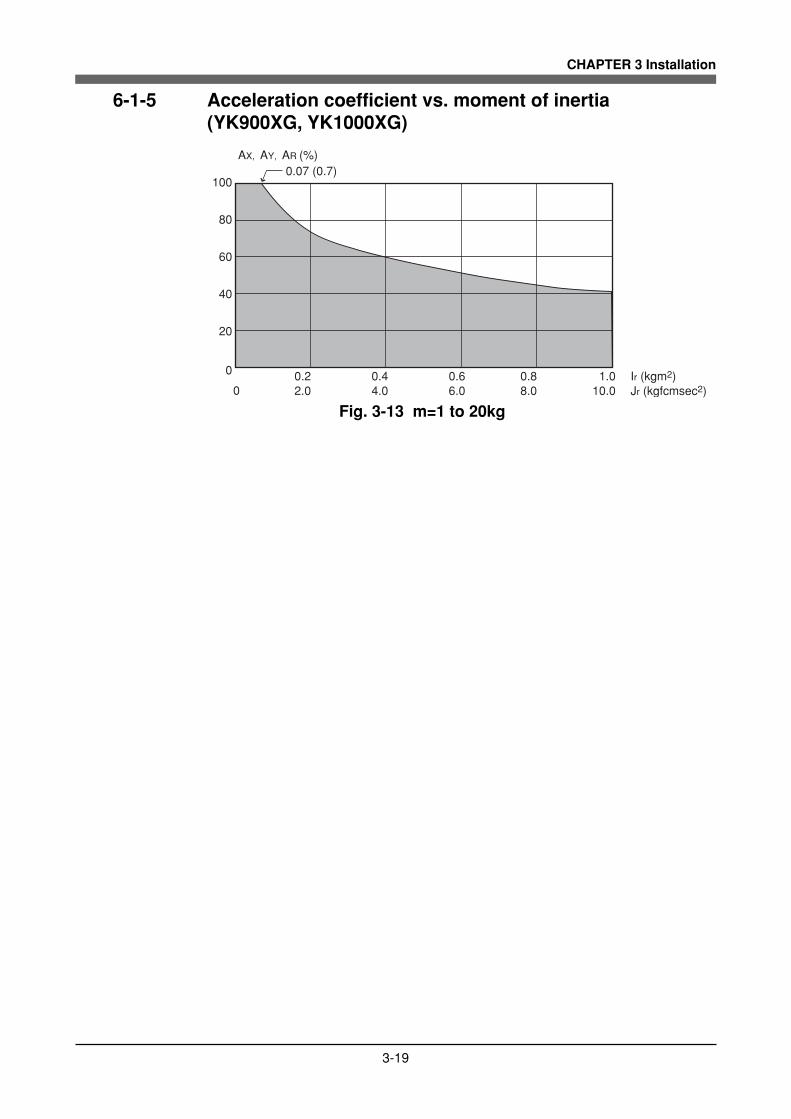
5) When the object's center line is offset from the rotation center.The equation for the moment of inertia, when the center of the cylinder isoffset by the distance "x" from the rotation center as shown in Fig. 3-18, isgiven as follows.
D
h
J=ρπD h
32g
WD8g
=
4
2
... (Eq. 3.5)
x
+ρπD hx
4g
2
+ Wxg
2
Center line
Rotation center
2
I=ρπD h
32
4
+ρπD hx
4
22 mD8
=2
mx2+
ρ : Density (kg/m3, kg/cm3)g : Gravitational acceleration (cm/sec2)
m : Mass of cylinder (kg)W : Weight of cylinder (kgf)
(kgfcmsec2)
(kgm2)
Fig. 3-18
In the same manner, the moment of inertia of a cylinder as shown in Fig. 3-19is given by
W4g
=
... (Eq. 3.6)
D4
h3
(2 2
+ )
h
D
x
Cneter line
J=ρπ D h
16g+
2 D4
h3
(2 2
+ )ρπ D h x
4g
2 2
+ Wxg
2
I=ρπ D h
16+
2 D4
h3
(2 2
+ )ρπ D h x
4
2 2 m4
=D4
h3
(2 2
+ ) + mx2
(kgfcmsec2)
(kgm2)
Fig. 3-19
In the same manner, the moment of inertia of a prism as shown in Fig. 3-20 isgiven by
J=ρabc(a + b )
12g
W(a + b )12g
=
2
2
... (Eq. 3.7)
2
2
+ρabcx
g
Wxg
+
2
2
a
c
bx
Center line
I=ρabc(a + b )
12
2 2
+ ρabcx2= m(a +b )12
2 2
+ mx2
m : Mass of prism (kg)W : Weight of prism (kgf)
(kgfcmsec2)
(kgm2)
Fig. 3-20
3-23
CHAPTER 3 Installation
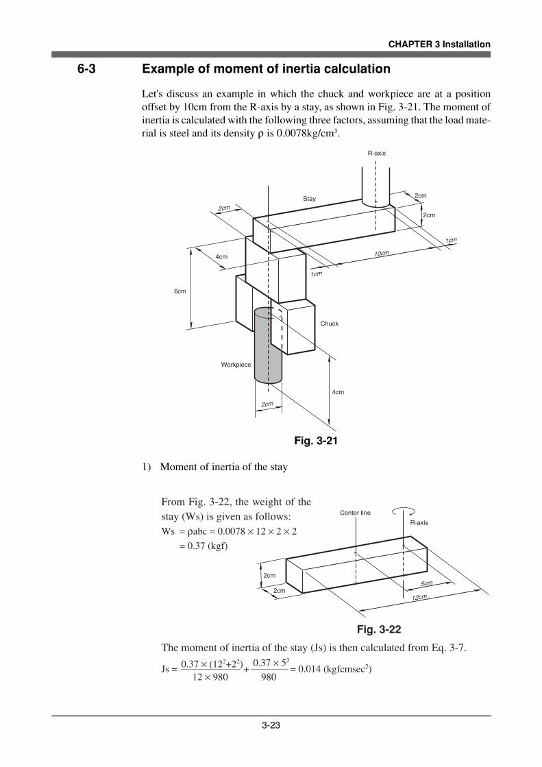
6-3 Example of moment of inertia calculation
Let's discuss an example in which the chuck and workpiece are at a positionoffset by 10cm from the R-axis by a stay, as shown in Fig. 3-21. The moment ofinertia is calculated with the following three factors, assuming that the load mate-rial is steel and its density ρ is 0.0078kg/cm3.
10cm
2cm
2cm
R-axis
1cm
1cm
2cm
2cm
4cm
6cm
4cm
Stay
Chuck
Workpiece
Fig. 3-21
1) Moment of inertia of the stay
From Fig. 3-22, the weight of thestay (Ws) is given as follows:Ws = ρabc = 0.0078 × 12 × 2 × 2 = 0.37 (kgf)
The moment of inertia of the stay (Js) is then calculated from Eq. 3-7.
Js = 0.37 × (122+22) +
0.37 × 52
= 0.014 (kgfcmsec2)12 × 980 980
Fig. 3-22
12cm
2cm
2cm
Center line
5cm
R-axis

3-24
CHAPTER 3 Installation
2) Moment of inertia of the chuck
When the chuck form resem-bles that shown in Fig. 3-23,the weight of the chuck (Wc)isWc = 0.0078 × 2 × 4 × 6 = 0.37 (kgf)The moment of inertia of thechuck (Jc) is then calculatedfrom Eq. 3-7.
Jc = 0.37 × (22+42)
12 × 980 0.37 × 10²
+
980
= 0.038 (kgfcmsec2)
Fig. 3-23
10cm2cm
6cm
4cm
R-axis
3) Moment of inertia of workpiece
When the workpiece formresembles that shown in Fig.3-24, the weight of theworkpiece (Ww) is
Ww =ρπD2h
= 0.0078π × 22 × 4
4 4
= 0.098 (kgf)
The moment of inertia of theworkpiece (Jw) is then calcu-lated from Eq. 3-5.
Jw=0.097 × 22
+ 0.097 × 10²
8 × 980 980
= 0.010 (kgfcmsec2)
Fig. 3-24
10cm
4cm
R-axis
2cm
4) Total weight
The total weight (W) is calculated as follows:W = Ws + Wc + Ww = 0.84 (kgf)
5) Total moment of inertia
The total moment of inertia (J) is then obtained as follows:J = Js + Jc + Jw = 0.062 (kgfcmsec2)

3-25
CHAPTER 3 Installation
6-4 Attaching the end effector
WARNING
• Before attaching the end effector, be sure to turn off the controller.• When the end effector is attached by slot clamping, always observe the con-
ditions listed in Table 3-2. If these are ignored, the end effector may comeloose and fly off during robot operation, resulting in an accident or injury.
• In cases where other attachment methods are used, be sure that the endeffector will not come off when the loads listed in Table 3-1 are applied.
The user's end effector that attaches to the robot must have adequate strength andrigidity, as well as gripping force to prevent positioning errors. Table 3-1 showsthe maximum load that can be applied to the end effector attachment of eachrobot model. Recommended methods for attaching end effectors are shown inTable 3-2 and Fig. 3-27. Refer to Fig. 3-25 for details on the end effector attach-ment of each robot model. Refer to Fig. 3-3 for the depth of tapped hole andrecommended type of tap bolt. When checking end effector operation, refer to "6Trial Operation" in Chapter 1.

3-26
CHAPTER 3 Installation
Never loosen this bolt.
Spline shaft (hollow diameter φ14)
φ20 h7 0-0.021
End effector attachment area
40
M16×2, depth 20
YK500XG, YK600XG
Never loosen this bolt.
Spline shaft (hollow diameter φ18)
45
φ25 h7 0-0.021
M20×2.5, depth 20
YK600XGH, YK700XG, YK800XG, YK900XG, YK1000XG
End effector attachment area
Fig. 3-25
WARNING
• The tapped hole (see Figs. 3-25) provided on the lower part of the end effec-tor attachment should be used only for preventing the end effector from com-ing loose.
• Do not fasten the end effector just by using this tapped hole. If the end effec-tor is fastened only with this tapped hole, it may come loose from the attach-ment during robot operation and fly off resulting in accidents or injuries.
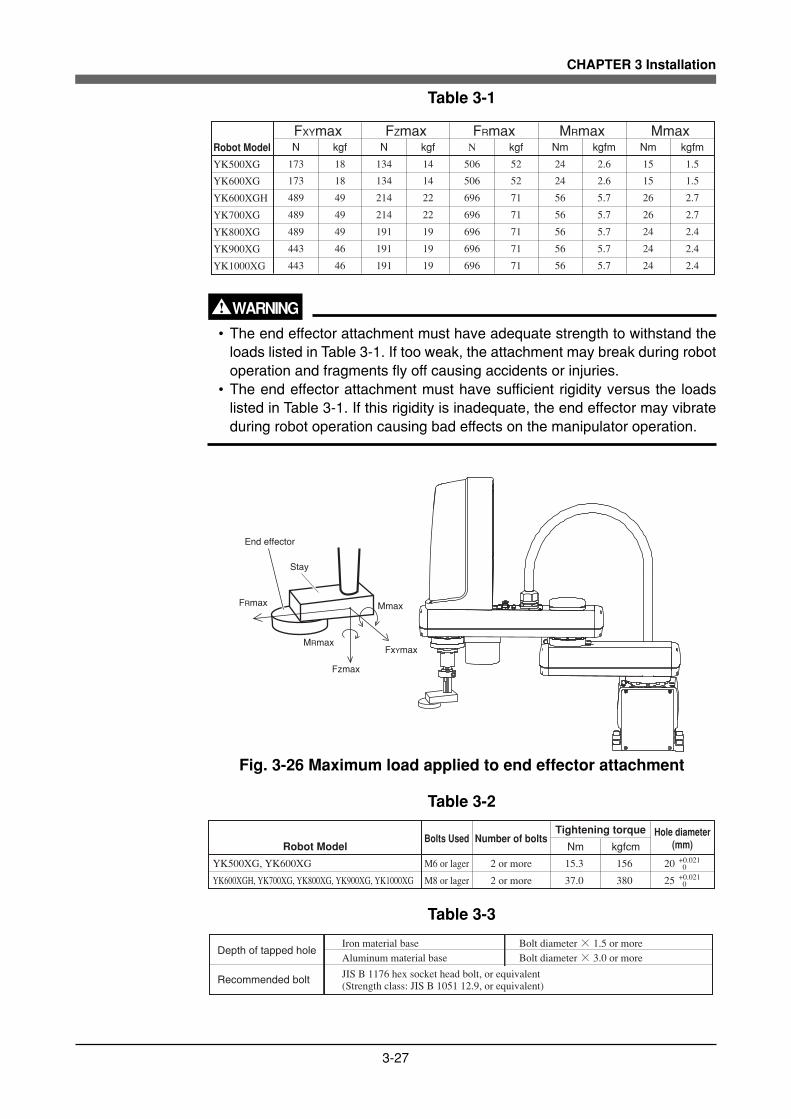
3-27
CHAPTER 3 Installation
Table 3-1
Robot Model
YK500XG
YK600XG
YK600XGH
YK700XG
YK800XG
YK900XG
YK1000XG
N kgf N kgf N kgf Nm kgfm Nm kgfmFXYmax FZmax FRmax MRmax Mmax
173 18 134 14 506 52 24 2.6 15 1.5
173 18 134 14 506 52 24 2.6 15 1.5
489 49 214 22 696 71 56 5.7 26 2.7
489 49 214 22 696 71 56 5.7 26 2.7
489 49 191 19 696 71 56 5.7 24 2.4
443 46 191 19 696 71 56 5.7 24 2.4
443 46 191 19 696 71 56 5.7 24 2.4
WARNING
• The end effector attachment must have adequate strength to withstand theloads listed in Table 3-1. If too weak, the attachment may break during robotoperation and fragments fly off causing accidents or injuries.
• The end effector attachment must have sufficient rigidity versus the loadslisted in Table 3-1. If this rigidity is inadequate, the end effector may vibrateduring robot operation causing bad effects on the manipulator operation.
FRmax
End effector
Stay
FxYmax
Fzmax
MRmax
Mmax
Fig. 3-26 Maximum load applied to end effector attachment
Table 3-2
Robot Model
YK500XG, YK600XG
YK600XGH, YK700XG, YK800XG, YK900XG, YK1000XG
Bolts Used Number of boltsNm kgfcm
M6 or lager 2 or more 15.3 156 20
M8 or lager 2 or more 37.0 380 25
Tightening torque Hole diameter (mm)
+0.021 0 +0.021 0
Table 3-3
Depth of tapped hole
Recommended bolt
Iron material baseAluminum material base
JIS B 1176 hex socket head bolt, or equivalent(Strength class: JIS B 1051 12.9, or equivalent)
Bolt diameter × 1.5 or moreBolt diameter × 3.0 or more

3-28
CHAPTER 3 Installation
Hole diameter
Bolt
Slot
Spline shaft
End effector or stay
Fig. 3-27

3-29
CHAPTER 3 Installation
6-5 Gripping force of end effector
The gripping force of the end effector must have a sufficient extra margin ofstrength versus the workpiece weight and reaction force applied to the workpieceduring robot operation. The reaction force applied to the workpiece during opera-tion can be calculated from the acceleration applied to the end effector attach-ment. The maximum acceleration on the end effector attachment of each robotmodel is listed in the table below. When the workpiece position is offset to theend effector attachment, the accelerations Amax and AXYmax become larger byan amount equal to the offset versus the arm length. When the R-axis rotatesduring operation, this acceleration ARmax must be taken into account.
Table 3-4 Maximum acceleration during robot operation
Robot Model
YK500XG
YK600XG
YK600XGH
YK700XG
YK800XG
YK900XG
YK1000XG
Amax(m/sec2) AXYmax(m/sec2) Azmax(m/sec2) ARmax(rad/sec2)
98 48 57 280
104 41 57 280
78 60 38 176
96 60 38 176
101 51 38 176
95 51 38 176
95 51 38 176
ARmax
Azmax
Amax AXYmax
(centrifugal acceleration)
(Tangential acceleration)
Fig. 3-28 Maximum acceleration on end effector attachment
WARNING
The gripping force of the end effector must have a sufficient extra margin ofstrength to prevent the workpiece from coming loose and flying off during robotoperation. If the gripping force is too weak, the workpiece may come loose andfly off causing accidents or injuries.

3-30
CHAPTER 3 Installation
7 Limiting the Movement Range with X-AxisMechanical Stoppers
In the YK-XG Series, the movement range can be limited by changing the X-axismechanical stopper positions. (See Fig. 3-29.) The Y-axis mechanical stopperpositions are fixed and cannot be changed. When the robot is shipped from thefactory, the movement range is set to the maximum. If the maximum movementrange is too large compared to the actual work range, or the manipulator mightinterfere with peripheral units, then the movement range can be limited as out-lined below. The X-axis mechanical stopper positions may slightly differ dependingon machining precision.
WARNING
Always turn off the controller before changing the movement range with me-chanical stoppers.
! CAUTION
When the mechanical stoppers are installed, the soft limits must be set to apoint inside the mechanical stopper positions. (Refer to "4 Setting the Soft Lim-its" in Chapter 4.)

3-31
CHAPTER 3 Installation
7-1 YK500XG, YK600XG, YK600XGH, YK700XG, YK800XG,YK900XG, YK1000XG
To change the X-axis mechanical stopper positions, for example, from the maxi-mum movement range (132°) to 87°, use the following procedure.
1) Prepare a hex wrench set.
2) Turn off the robot controller.
3) Place a sign indicating the robot is being adjusted, to keep others from touch-ing the controller switch.
4) Enter the safeguard enclosure.
5) Remove the screw plug, X-axis mechanical stopper bolt and washer as shownin Fig. 3-30. Then reinstall the mechanical stopper bolt and washer at theposition that determines the desired movement range by tightening the boltto the torque specified in Table 3-5.Reinstall the screw plug you removed, into the position where the X-axisstopper bolt was installed.
6) Check that the movement range is limited by the mechanical stoppers asdesired.
7) Go outside the safeguard enclosure.
8) Check that no one is inside the safeguard enclosure when turning on thecontroller.
Table 3-5
Bolt size Tightening torque (kgfcm) Tightening torque (Nm)
M8 380 37.2
M10 459 45.0
Robot Model
YK500XG,YK600XG
YK600XGH, YK700XG, YK800XG, YK900XG, YK1000XG
Use only YAMAHA genuine bolts or JIS B 1176 hex socket head bolts(strength class: JIS B 1051 12.9).

3-32
CHAPTER 3 Installation
Y-axis mechanical stopper
X-axis movable mechanical stopper
43° 12°
87° 132°
Fig. 3-29 X-axis movable mechanical stopper position
Screw plug X-axis stopper bolt Washer : YK500XG, YK600XG (1 washer) YK600XGH, YK700XG YK800XG, YK900XG, YK1000XG (2 washers)
Fig. 3-30 Changing the X-axis mechanical stopper position

3-33
CHAPTER 3 Installation
8 Working Envelope and Mechanical StopperPositions for Maximum Working EnvelopeWorking envelope of each robot and mechanical stopper positions for the maxi-mum working envelope are shown in "1-2 External view and dimensions" in Chap-ter 7.Here, those are described using the YK500XG as an example. Other robot mod-els are the same.
1) X and Y axes1. Do not attempt operation outside the working envelope. On the YK-XG
series, the origin can be set at a discrete position. The working envelopedescribed in this manual is an area with the robot frontal reference whenno load is applied.
2. Interference positions where a load may touch the robot within the work-ing envelope and their radii are shown in the figure. Here, "a", "b", "c" and"d" are the respective interference positions with the base front panel, baseside panel, base rear panel, and base corners. Be careful not to allow therobot load to interfere with any part of the robot.The Z-axis spline may touch the base or the Y-axis arm may touch thewire harness before the robot strikes the X-axis or Y-axis mechanical stop-pers, so use caution.
3. Interference positions where a load might touch the robot within the maxi-mum movement range and their radii are shown in the figure. Here, "a","b", "c" and "d" are the respective interference positions with the basefront panel, base side panel, base rear panel and the base corners. The Z-axis spline may touch the base or the Y-axis arm may touch the wire har-ness before the robot strikes the X-axis or Y-axis mechanical stoppers, souse caution.
2) Z-axisDo not attempt work outside the working envelope. In particular, do not at-tempt work in the area between the working envelope and mechanical stop-per position. Mechanical stoppers are installed at both the upper and lowerends of the movement range.
WARNING
The robot cable, user wiring or tubing may be damaged if the robot load inter-feres with them resulting in hazardous robot malfunctions. Do not operate atpoints where the load may interfere with the robot cable, user wiring or tubing.
3) R-axisThe R-axis has no mechanical stoppers.
! CAUTION
Since the R-axis has no mechanical stoppers, make certain that the end effec-tor wiring and tubing do not become entangled during operation.

3-34
CHAPTER 3 Installation
4) Robot overrun during impacts with mechanical stopperA urethane damper is installed to absorb the shock when an impact occurswith the mechanical stopper, so a certain amount of overrun occurs when therobot strikes the mechanical stopper. Use caution and take overrun into ac-count since the end effector may interfere with the robot body and peripheralequipment or the robot body may interfere with the peripheral equipment.Maximum overrun amounts are listed below (for normal operation, maxi-mum payload, maximum speed).
Robot model
YK500XG,YK600XG
YK600XGH, YK700XG to YK800XG
5mm
5mm
Lower end
5mm
5mm
Upper end
Z-axis
12°12°
Y-axis
9°9°
X-axis
Note: Here, ° (deg.) is the overrun angle at the X-axis and Y-axis joints.
(1) If the X-axis, Y-axis or Z-axis mechanical stopper is deformed or dam-aged by impacts, please contact our sales office or dealer. Using the de-formed or damaged mechanical stopper is dangerous, so it must be re-placed.
(2) When the robot strikes the X-axis or Y-axis mechanical stopper or an-other object, or when the R-axis collides with an object, speed reductiongears are locked while being meshed if the collision impact is large. Ifthis happens, please contact our sales office or dealer.

CHAPTER 4
Adjustment
1 Overview ..........................................................................................................4-1
2 Safety Precautions ...........................................................................................4-1
3 Adjusting the Origin ..........................................................................................4-23-1 Absolute reset method.................................................................................................... 4-3
3-1-1 Sensor method (X-axis, Y-axis, and R-axis) ...................................................................... 4-3
3-1-2 Stroke end method (Z-axis) ............................................................................................... 4-3
3-2 Machine reference .......................................................................................................... 4-4
3-3 Absolute reset procedures.............................................................................................. 4-5
3-3-1 Sensor method (X-axis, Y-axis, and R-axis) ...................................................................... 4-5
3-3-2 Stroke end method (Z-axis) ............................................................................................... 4-7
3-4 Changing the origin position and adjusting the machine reference ................................ 4-8
3-4-1 Sensor method .................................................................................................................. 4-93-4-1-1 YK500XG, YK600XG, YK600XGH, YK700XG, YK800XG, YK900XG, YK1000XG ............ 4-9
3-4-2 Stroke end method .......................................................................................................... 4-273-4-2-1 YK500XG, YK600XG, YK600XGH, YK700XG, YK800XG, YK900XG, YK1000XG .......... 4-27
4 Setting the Soft Limits ....................................................................................4-31
5 Setting the Standard Coordinates ..................................................................4-345-1 Standard coordinate setting using a standard coordinate setup jig (option)................. 4-35
6 Affixing the Stickers for Movement Directions and Axis Names .....................4-38

MEMO

4-1
CHAPTER 4 Adjustment
1 Overview
YAMAHA robots have been completely adjusted at the factory or by the salesrepresentative before shipment, including the origin position adjustment. If theoperating conditions are changed and the robot must be adjusted, then follow theprocedures described in this chapter.
2 Safety Precautions
(1) Read and understand the contents of this chapter completely before attempt-ing to adjust the robot.
(2) Place a conspicuous sign indicating the robot is being adjusted, to preventothers from touching the controller switch, programming unit or operationpanel.
(3) If a safeguard enclosure has not yet been provided right after installation ofthe robot, rope off or chain off the movement area around the manipulator inplace of a safeguard enclosure, and observe the following points.qUse stable posts which will not fall over easily.wThe rope or chain should be easily visible by everyone around the robot.ePlace a conspicuous sign prohibiting the operator or other personnel from
entering the movement area of the manipulator.
(4) To check operation after adjustment, refer to "6. Trial Operation" in Chapter 1.

4-2
CHAPTER 4 Adjustment
3 Adjusting the Origin
All models of the YK-XG series robots use an absolute type position detector.The origin position (zero pulse point) can be determined by absolute reset. Onceabsolute reset is performed, you do not have to repeat absolute reset when turningthe power on next time. However, absolute reset is required if any of the follow-ing cases occur. The robot is shipped from the factory in condition "c" (below), soplease perform absolute reset after installing the robot. For more details on abso-lute reset, refer to "Absolute Reset" in Chapter 4 of the "YAMAHA Robot Con-troller User's Manual".
a. Absolute-related error occurred on the axis.b. Power drop was detected in the absolute battery for the driver installed
inside the robot controller.c. Cable connecting the robot unit to the controller was disconnected.
(This is the status when shipped from the factory.)d. Robot generation was changed.e. Parameters were initialized.f. Axis parameters "Origin shift", "Origin method", "Origin direction" or
"Motor direction" were changed.g. Motor was replaced. (Motor wiring connector was removed.)h. Data in the ALL data file (extension: ALL) or parameter file (extension:
PRM) was written into the controller by way of the RS-232C.
The following sections explain how to perform absolute reset.
! CAUTION
• If any of the above cases occur after installing the robot, absolute reset mustbe performed again. To perform absolute reset, move the robot arms back totheir origin positions where the robot does not interfere with peripheral equip-ment after the setup is complete.
• After performing absolute reset, move the robot to a known point to checkwhether the origin position is correctly set. When doing this check, move therobot at the slowest possible speed.
• The standard coordinate and point data must be reset when the origin posi-tion is changed.
• Make point data setting after changing the origin position. After changing theorigin position, do not use the previous point data.
There are three absolute reset methods for the YK-XG series: the sensor method,mark method, and stroke end method. The X-axis, Y-axis, and R-axis use thesensor method as the initial setting, while the Z-axis uses the stroke end method.

4-3
CHAPTER 4 Adjustment
3-1 Absolute reset method
3-1-1 Sensor method (X-axis, Y-axis, and R-axis)
In the sensor method, the target axis is automatically operated for the absolutereset, and the absolute reset is performed at the position where the proximitysensor provided on the target axis detects the detection area (dog). The absolutereset in the sensor method can be executed with the teaching pendant (MPB), RS-232C communication, and dedicated input.
WARNING
Serious injury might occur from physical contact with the robot during opera-tion. Never enter within the robot movement range during absolute reset.
! CAUTION
The origin cannot be detected in any axis which is not positioned on the plusside from the origin (see Fig. 4-2) before starting the return-to-origin operation.(Factory setting at shipment.) In this case, press the STOP key to interrupt thereturn-to-origin operation, move the target axis to the plus side of the origin,and reperform the origin return operation. If the return-to-origin operation is notinterrupted, the robot will continue the operation and may collide with the me-chanical stopper or a peripheral device. Since a mechanical stopper is not pro-vided in the R-axis, the wiring and piping installed on the end effecter may bewound up by the operation.
3-1-2 Stroke end method (Z-axis)
In the stroke end method, absolute reset is performed at a position slightly backedoff from the stroke end, after the Z-axis contacts the mechanical stopper andstroke end is detected.
WARNING
Serious injury might occur from physical contact with the robot during opera-tion. Never enter within the robot movement range during absolute reset.

4-4
CHAPTER 4 Adjustment
3-2 Machine referenceThe YK-XG series position detectors are resolvers that have four positions whereabsolute reset can be performed per motor revolution. If the sensor method isused for the absolute reset, the origin position will be set at the positions whereabsolute reset can be performed soon after the origin sensor reacts to the dog (theorigin signal is detected). The machine reference means the position relationshipof the position where the robot detects the origin signal to the position where theabsolute reset can be performed soon after detection (see Fig. 4-1). The machinereference is expressed with the ratio of interval A to interval B shown in Fig. 4-1.Interval A is the minimum distance between the positions where absolute resetcan be performed and interval B is the distance between the position where theorigin signal is detected and the position where absolute reset can be performedsoon after the origin signal detection. The machine reference value (unit: %) isdisplayed on the optional MPB screen.
Machine reference value = B/A × 100(%)
! CAUTION
The machine reference must be adjusted within a specified range to keep therepeatability precision of the absolute reset position (The machine reference isfactory-adjusted prior to shipping). If the origin position is changed, the ma-chine reference must be readjusted. For information on how to adjust the ma-chine reference, refer to "3-4 Changing the origin position and adjusting themachine reference" in Chapter 4. When the temperature of the robot joint sec-tions is high immediately after the robot has been operated, the machine refer-ence value might be outside the specified range (40 to 60%). When checking oradjusting the machine reference value, always make sure that the temperatureof the robot joint sections has returned to room temperature.
Recommended machine reference value: 40 to 60%
Machine referenceOrigin signal detection
Origin signal
Resolver
Positions where absolute reset can be performed
One motor revolution
BA
ON
OFF
Machine reference display on MPB screen
MANUAL >RST. ABS 50% [MG] [S0H0J]
Machine reference (%)
M1= 50
M4= 66
M2= 56 M3= 52
M1 M2 M3 M4 M5
R-axis X-axis Y-axis Z-axis
MPB
Fig. 4-1

4-5
CHAPTER 4 Adjustment
3-3 Absolute reset procedures
3-3-1 Sensor method (X-axis, Y-axis, and R-axis)
WARNING
Serious injury might occur from physical contact with the robot during opera-tion. Never enter within the robot movement range during absolute reset.
The operation procedure using the MPB is described next. (Press the ESC key onthe MPB if you want to return to the preceding step.) See the "YAMAHA RobotController User's Manual" for information on operating the robot controller.
1) Check that no one is inside the safeguard enclosure and then turn on thecontroller.
2) Place a sign indicating the robot is being adjusted, to keep others from touch-ing the controller switch or operation panel.
3) Set the controller to MANUAL mode, if not in MANUAL mode.
4) Press the F13 (LOWER+F3) key to select "RST. ABS".
5) Select the axis for absolute reset. (X-axis: M1, Y-axis: M2, R-axis: M4)To perform absolute reset on all axes, select "ALL" with the F11 (LOWER+F1)key.
! CAUTION
The Z-axis of the stroke end method first rises during the absolute reset of allaxes (default setting). Be careful that your fingers do not get pinched or crushedby any sudden movement.
6) Check that the absolute reset axis must be positioned at the plus side of theorigin. (See Fig. 4-2.) If it is not at the plus side, then press the jog key tomove the target axis to the plus side.
7) Since the message "Reset ABS encoder OK?" is displayed, check that thereare not any obstacles in the robot movement range, and press the F4 key(YES).

4-6
CHAPTER 4 Adjustment
8) After the absolute reset is completed, check that the machine reference valuedisplayed on the MPB is between 40 and 60 (recommended range). If themachine reference value is outside the recommended range, then the nextabsolute reset may not be properly performed. In this case, refer to "3-4 Chang-ing the origin position and adjusting the machine reference", and make thenecessary adjustments.
Return-to-origin is impossible from this area.
Origin position at shipment
Return-to-origin direction
Plus side Minus side
Fig. 4-2

4-7
CHAPTER 4 Adjustment
3-3-2 Stroke end method (Z-axis)
WARNING
Serious injury might occur from physical contact with the robot during opera-tion.Never enter within the robot movement range during absolute reset.
The operation procedure using the MPB is described next. (Press the ESC key onthe MPB if you want to return to the preceding step.) See the "YAMAHA RobotController User's Manual" for information on operat-ing the robot controller.
1) Check that no one is inside the safeguard enclosure and then turn on thecontroller.
2) Place a sign indicating the robot is being adjusted, to keep others from touch-ing the controller switch or operation panel.
3) Set the controller to MANUAL mode, if not in MANUAL mode.
4) Press the F13 (LOWER+F3) key to select "RST. ABS".
5) Select M3 (Z-axis).
6) Since the message "Reset ABS encoder OK?" is displayed, check that thereare not any obstacles in the robot movement range, and press the F4 key(YES).
7) After absolute reset is complete, check that the adjustment machine refer-ence value displayed on the MPB is within the absolute reset tolerance range(33 to 67).
! CAUTION
Use the following procedure to display the adjustment machine referencevalue. When adjusting the machine reference value, always check the ad-justment machine reference value with this procedure.
(1) Press the MODE key.(2) Press the F3 key to enter MANUAL mode.(3) Press the F13 key (LOWER+F3) to select "ABS Reset".(4) After the Z-axis absolute reset is complete, press the F10 (UPPER+F5) key
to display the adjustment machine reference value (%).
If the machine reference value is outside the absolute reset tolerance range,then the next absolute reset may not be properly performed. In this case,make the necessary adjustments by referring to "3-4 Changing the originposition and adjusting the machine reference" in Chapter 4.

4-8
CHAPTER 4 Adjustment
3-4 Changing the origin position and adjusting the machinereference
! CAUTION
• If the origin position has been changed, then the absolute reset must beperformed, the machine reference must be adjusted, and the standard coor-dinate and point data must be reset.
• If any machine reference is adjusted, the origin position may change. Beforethe adjustment, mark off the reference mark at the current origin position onthe main body of the robot. After the machine reference is adjusted, be sureto check that the origin position has not deviated. If the origin position changesafter the machine reference has been adjusted, then the standard coordi-nate and point data must be reset.

4-9
CHAPTER 4 Adjustment
3-4-1 Sensor method
3-4-1-1 YK500XG, YK600XG, YK600XGH, YK700XG, YK800XG,YK900XG, YK1000XG
1-1 Adjusting the X-axis machine reference
! CAUTION
The origin position may change due to machine reference adjustment. If it oc-curs, you must set point data again.
The adjustment method for the X-axis machine reference is as follows.
1) Prepare a hex wrench set.
2) Check that no one is inside the safeguard enclosure and then turn on thecontroller.
3) Perform the absolute reset from outside the safeguard enclosure.Refer to "3-3 Absolute reset procedures" for information about the absolutereset method.
4) If any machine reference value displayed on the MPB is not in the rangebetween 40 and 60 (recommended range) after the absolute reset has beencompleted, then proceed with the following adjustment procedure.
5) Place a sign indicating that the robot is being adjusted in order to keep othersfrom operating the controller or operation panel.
6) Turn off the controller and enter the safeguard enclosure.
7) Mark off the reference mark at the current origin position on the X-axis jointarea of the robot.At this time, be careful to prevent the origin position from deviating since theX-axis arm is touched.
8) Remove the cover.
9) Scribe a mark on the position of the X-axis origin sensor stay.
10) Using the hex wrench, loosen the two bolts securing the X-axis origin sensorstay. (See Fig. 4-3.)
! CAUTION
The bolts only need to be loosened, and do not need to be completely re-moved.

4-10
CHAPTER 4 Adjustment
11) Move the X-axis origin sensor stay in the following manner and then secureit with the bolts.
NOTE
• When the machine reference is less than 40%, move the stay in direction q:See Fig. 4-3 (b).
• When the machine reference is more than 40%, move the stay in direction w:See Fig. 4-3(b).
As an approximate guide, a 1mm movement equals to 100%.
12) Go out of the safeguard enclosure, and check that no one is inside the safe-guard enclosure. Then turn on the controller.
13) Perform the absolute reset from outside the safeguard enclosure.
14) After the absolute reset is completed, read the machine reference value dis-played on the MPB.
15) If the machine reference value is in the range between 40 and 60 (recom-mended range), then the machine reference has been completely adjusted.If it is outside the recommended range, then repeat the procedure that startsin 5) to readjust it.
16) Reattach the cover after the adjustment is complete.
X-axis origin dog
Fig. 4-3 (a)

4-11
CHAPTER 4 Adjustment
X-axis origin sensor stay
X-axis origin sensor
Bolt
Cover
q
w
Fig. 4-3 (b)

4-12
CHAPTER 4 Adjustment
1-2 Changing the X-axis origin position
The X-axis origin position can be changed to any position in the range from thefront position of the X-axis arm base to a maximum of 120° clockwise andcounterclockwise at 30° intervals, by changing the positions of the dog and themounting bolt for the X-axis speed reduction unit as shown in Fig. 4-4.
! CAUTION
• If the origin position has been changed, then the absolute reset must beperformed, the machine reference must be adjusted, and the standard coor-dinate and point data must be reset.
• The dog and bolt might come off and cause the joint to lock up unless youapply "Screw Lock" to them and tighten to the specified torque.
The following describes the method for changing the X-axis origin position, forexample, to a position 90° counterclockwise.
1) Prepare the necessary tools.• Hex wrench set • Torque wrench• Phillips screwdriver • Screw Lock (thread sealant)• Phillips screwdriver bit • Hex bit
2) Check that no one is inside the safeguard enclosure and then turn on thecontroller.
3) Perform the absolute reset from outside the safeguard enclosure.Refer to "3-3 Absolute reset procedures" for information about the absolutereset method.
4) Place a sign indicating that the robot is being adjusted in order to keep othersfrom operating the controller or operation panel.
5) Turn off the controller and enter the safeguard enclosure.
6) Remove the cover. (See Fig. 4-5 (a).)
7) Using the hex wrench, loosen the two bolts securing the X-axis origin sensor stay.
8) Remove the X-axis origin sensor stay.
9) Remove the dog and hex nut through the elongated hole.We recommend using the Phillips screwdriver bit and wrench to remove thedog since it is secured with "Screw Lock".
10) Rotate the X-axis arm 90° counterclockwise. (See Fig. 4-5 (b).)
11) Remove the bolt located opposite the elongated hole.
12) Apply "Screw Lock" to the dog and nut, insert them into the tapped hole wherethe bolt was attached, and tighten to the specified torque. (See Fig. 4-5 (c).)
13) Return the X-axis arm to the current origin position. (See Fig. 4-5 (d).)
14) Apply "Screw Lock" to the bolt, insert it into the tapped hole where the dogwas attached, and tighten to the specified torque.

4-13
CHAPTER 4 Adjustment
15) Temporarily fasten the X-axis origin sensor stay using the bolts. At this point,check that the sensor does not interfere with other parts while turning the X-axis arm by hand.
16) Go out of the safeguard enclosure, and check that no one is inside the safe-guard enclosure. Then turn on the controller.
17) Perform the absolute reset from outside the safeguard enclosure.
18) After the absolute reset is completed, read the machine reference value dis-played on the MPB.
19) If the machine reference value is in the range between 40 and 60 (recom-mended range), then the origin position has been correctly changed. Fullytighten the bolts to secure the X-axis origin sensor stay. If it is outside therecommended value, then adjust the machine reference by referring to "1-1Adjusting the X-axis machine reference".
20) Reattach the cover after the adjustment is complete.
Dog
Factory-preset X-axis origin position
X-axis origin position adjustable range
120°
90°
60°
30°
120°
90°
60°30°
Mounting bolt for X-axis speed reduction unit
Fig. 4-4

4-14
CHAPTER 4 Adjustment
Elongated hole
Bolt
Cover
Hex nut
Dog
X-axis origin sensor stay
Fig. 4-5 (a)
Bolt
X-axis arm
Fig. 4-5 (b)

4-15
CHAPTER 4 Adjustment
Dog
Hex nut
Dog Tightening torque (kgfcm) Tightening torque (cNm)
M4×30 16 160
M5×40 32 320
Robot model
YK500XG,YK600XG
YK600XGH, YK700XG, YK800XG, YK900XG, YK1000XG
Recommended "Screw Lock": LOCTITE 262 (made by Henkel Corporation)
Fig. 4-5 (c)
Bolt
Bolt Tightening torque (kgfcm) Tightening torque (Nm)
M4×30 46 4.5
M5×40 92 9.0
Robot model
YK500XG,YK600XG
YK600XGH, YK700XG, YK800XG, YK900XG, YK1000XG
Recommended "Screw Lock": LOCTITE 262 (made by Henkel Corporation)Use only YAMAHA genuine bolts or JIS B 1176 hex socket head bolts (strength class: JIS B 1051 12.9).
Fig. 4-5 (d)

4-16
CHAPTER 4 Adjustment
2-1 Adjusting the Y-axis machine reference
! CAUTION
The origin position may change due to machine reference adjustment. If it oc-curs, you must set point data again.
The adjustment method for the Y-axis machine reference is as follows.
1) Prepare a hex wrench set.
2) Check that no one is inside the safeguard enclosure and then turn on thecontroller.
3) Perform the absolute reset from outside the safeguard enclosure.Refer to "3-3 Absolute reset procedures" for information about the absolutereset method.
4) If any machine reference value displayed on the MPB is not in the rangebetween 40 and 60 (recommended range) after the absolute reset has beencompleted, then proceed with the following adjustment procedure.
5) Place a sign indicating that the robot is being adjusted in order to keep othersfrom operating the controller or operation panel.
6) Turn off the controller and enter the safeguard enclosure.
7) Mark off the reference mark at the current origin position on the Y-axis jointarea of the robot.At this time, be careful to prevent the origin position from deviating since theY-axis arm is touched.
8) Remove the cover.
9) Scribe a mark on the position of the Y-axis origin sensor stay.
10) Using the hex wrench, loosen the two bolts securing the Y-axis origin sensorstay. (See Fig. 4-6.)
! CAUTION
The bolts only need to be loosened, and do not need to be completely re-moved.

4-17
CHAPTER 4 Adjustment
11) Move the Y-axis origin sensor stay in the following manner and then secure itwith the bolts.
NOTE
• When the machine reference is less than 40%, move the stay in direction q:See Fig. 4-6.
• When the machine reference is more than 40%, move the stay in direction w:See Fig. 4-6.
As an approximate guide, a 0.8mm movement equals to 100%.
12) Go out of the safeguard enclosure, and check that no one is inside the safe-guard enclosure. Then turn on the controller.
13) Perform the absolute reset from outside the safeguard enclosure.
14) After the absolute reset is completed, read the machine reference value dis-played on the MPB.
15) If the machine reference value is in the range between 40 and 60 (recom-mended range), then the machine reference has been completely adjusted.If it is outside the recommended range, then repeat the procedure that startsin 5) to readjust it.
16) Reattach the cover after the adjustment is complete.

4-18
CHAPTER 4 Adjustment
Y-axis origin dog
Y-axis origin sensor
Y-axis origin sensor stay
Cover
Bolt
q
w
Fig. 4-6

4-19
CHAPTER 4 Adjustment
2-2 Changing the Y-axis origin position
The Y-axis origin position can be changed to any position in the range from thefront position of the Y-axis arm and X-axis arm to a maximum of 120° clockwiseand counterclockwise at 30° intervals, by changing the positions of the dog andthe mounting bolt for the Y-axis speed reduction unit as shown in Fig. 4-7.
! CAUTION
• If the origin position has been changed, then the absolute reset must beperformed, the machine reference must be adjusted, and the standard coor-dinate and point data must be reset.
• The dog and bolt might come off and cause the joint to lock up unless youapply "Screw Lock" to them and tighten to the specified torque.
The following describes the method for changing the Y-axis origin position, forexample, to a position 90° counterclockwise.
1) Prepare the necessary tools.• Hex wrench set • Torque wrench• Phillips screwdriver • Screw Lock (thread sealant)• Phillips screwdriver bit • Hex bit
2) Check that no one is inside the safeguard enclosure and then turn on thecontroller.
3) Perform the absolute reset from outside the safeguard enclosure.Refer to "3-3 Absolute reset procedures" for information about the absolutereset method.
4) Place a sign indicating that the robot is being adjusted in order to keep othersfrom operating the controller or operation panel.
5) Turn off the controller and enter the safeguard enclosure.
6) Remove the cover. (See Fig. 4-8 (a).)
7) Using the hex wrench, loosen the two bolts securing the Y-axis origin sensor stay.
8) Remove the Y-axis origin sensor stay.
9) Remove the dog and hex nut through the elongated hole. (See Fig. 4-8 (b).)We recommend using the Phillips screwdriver bit and wrench to remove thedog since it is secured with "Screw Lock".
10) Rotate the Y-axis arm 90° counterclockwise. (See Fig. 4-8 (c).)
11) Remove the bolt located opposite the elongated hole.
12) Apply "Screw Lock" to the dog and nut, insert them into the tapped hole wherethe bolt was attached, and tighten to the specified torque. (See Fig. 4-8 (d).)
13) Return the Y-axis arm to the current origin position. (See Fig. 4-8 (e).)
14) Apply "Screw Lock" to the bolt, insert it into the tapped hole where the dogwas attached, and tighten to the specified torque.
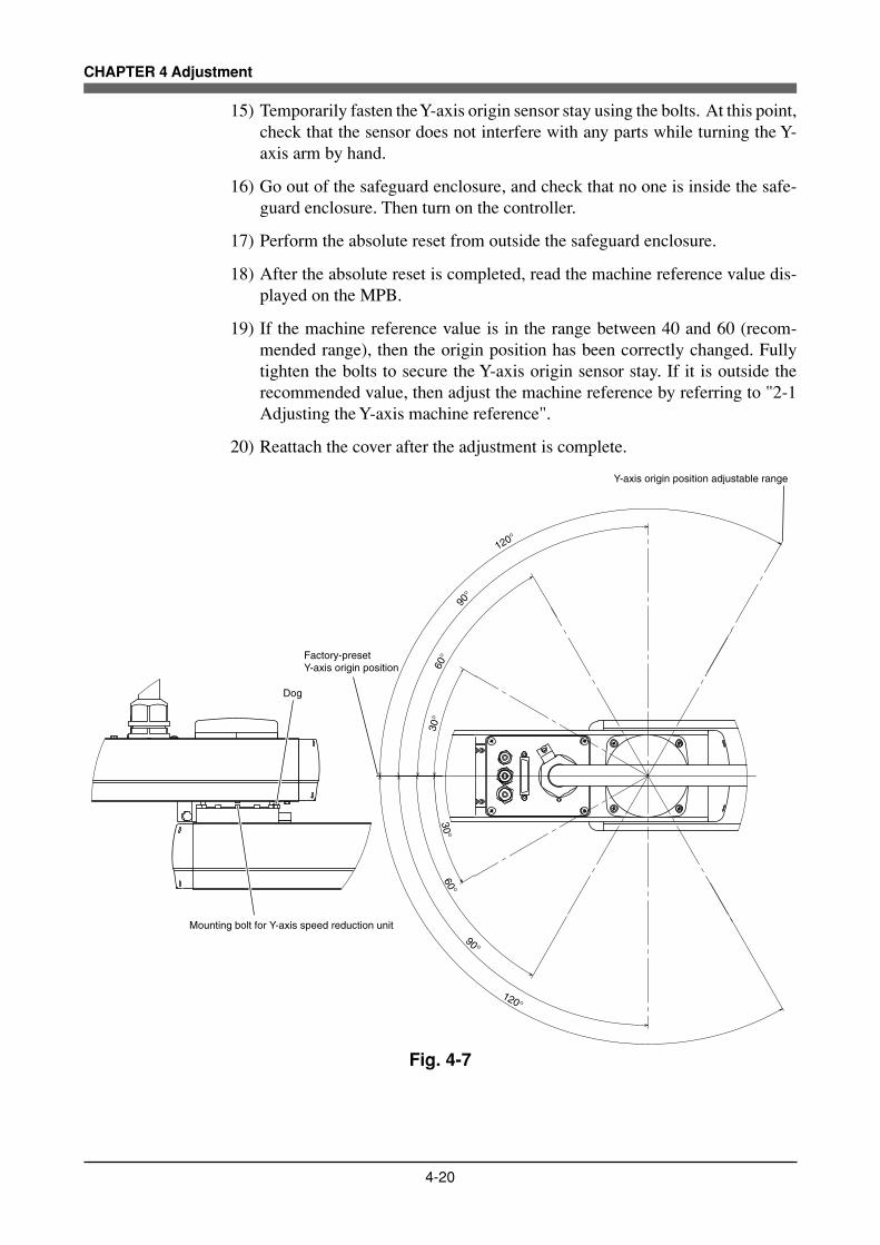
4-20
CHAPTER 4 Adjustment
15) Temporarily fasten the Y-axis origin sensor stay using the bolts. At this point,check that the sensor does not interfere with any parts while turning the Y-axis arm by hand.
16) Go out of the safeguard enclosure, and check that no one is inside the safe-guard enclosure. Then turn on the controller.
17) Perform the absolute reset from outside the safeguard enclosure.
18) After the absolute reset is completed, read the machine reference value dis-played on the MPB.
19) If the machine reference value is in the range between 40 and 60 (recom-mended range), then the origin position has been correctly changed. Fullytighten the bolts to secure the Y-axis origin sensor stay. If it is outside therecommended value, then adjust the machine reference by referring to "2-1Adjusting the Y-axis machine reference".
20) Reattach the cover after the adjustment is complete.
Dog
Mounting bolt for Y-axis speed reduction unit
Factory-preset Y-axis origin position
Y-axis origin position adjustable range
120°
90°
60°
30°
120°
90°
60°30°
Fig. 4-7

4-21
CHAPTER 4 Adjustment
Cover
Elongated hole
Y-axis origin sensor stay
Bolt
Fig. 4-8 (a)

4-22
CHAPTER 4 Adjustment
Dog
Hex nut
Fig. 4-8 (b)
Bolt
Y-axis arm
X-axis arm
Fig. 4-8 (c)

4-23
CHAPTER 4 Adjustment
Dog
Hex nut
Dog Tightening torque (kgfcm) Tightening torque (cNm)
M3×30 9 90
M4×30 16 160
Robot model
YK500XG,YK600XG
YK600XGH, YK700XG, YK800XG, YK900XG, YK1000XG
Recommended "Screw Lock": LOCTITE 262 (made by Henkel Corporation)
Fig. 4-8 (d)
Bolt
Bolt Tightening torque (kgfcm) Tightening torque (Nm)
M3×30 20 2.0
M4×30 46 4.5
Robot model
YK500XG,YK600XG
YK600XGH, YK700XG, YK800XG, YK900XG, YK1000XG
Recommended "Screw Lock": LOCTITE 262 (made by Henkel Corporation)Use only YAMAHA genuine bolts or JIS B 1176 hex socket head bolts (strength class: JIS B 1051 12.9).
Fig. 4-8 (e)

4-24
CHAPTER 4 Adjustment
3 Adjusting the R-axis machine reference
The adjustment method for the R-axis machine reference is as follows.
1) Prepare a hex wrench set.
2) Check that no one is inside the safeguard enclosure and then turn on thecontroller.
3) Perform the absolute reset from outside the safeguard enclosure.Refer to "3-3 Absolute reset procedures" for information about the absolutereset method.
4) If any machine reference value displayed on the MPB is not in the rangebetween 40 and 60 (recommended range) after the absolute reset has beencompleted, then proceed with the following adjustment procedure.
5) Place a sign indicating that the robot is being adjusted in order to keep othersfrom operating the controller or operation panel.
6) Turn off the controller and enter the safeguard enclosure.
7) Mark off the reference mark at the current origin position on the R-axis areaof the robot.At this time, be careful not to touch the tool at the tip of the robot arm so thatthe origin position does not shift.
8) Remove the cover.
9) Scribe a mark on the position of the R-axis origin sensor stay.
10) Using the hex wrench, loosen the two bolts securing the R-axis origin sensorstay. (See Fig. 4-9.)
! CAUTION
The bolts only need to be loosened, and do not need to be completely re-moved.
11) Move the R-axis origin sensor stay in the following manner and then secureit with the bolts.
NOTE
• When the machine reference is less than 40%, move the stay in direction q:See Fig. 4-9.
• When the machine reference is more than 40%, move the stay in direction w:See Fig. 4-9.
As an approximate guide, a 1.9mm movement equals to 100%.

4-25
CHAPTER 4 Adjustment
12) Go out of the safeguard enclosure, and check that no one is inside the safe-guard enclosure. Then turn on the controller.
13) Perform the absolute reset from outside the safeguard enclosure.
14) After the absolute reset is completed, read the machine reference value dis-played on the MPB.
15) If the machine reference value is in the range between 40 and 60 (recom-mended range), then the machine reference has been completely adjusted.If it is outside the recommended range, then repeat the procedure that startsin 5) to readjust it.
16) Reattach the cover after the adjustment is complete.

4-26
CHAPTER 4 Adjustment
R-axis origin dog
Bolt
R-axis origin sensor stay
R-axis origin sensor
q
w
Cover
Fig. 4-9

4-27
CHAPTER 4 Adjustment
3-4-2 Stroke end method
The stroke end method is employed on the YK-XG series robots for the absolutereset of the Z-axis. The origin position of the Z-axis is fixed at the upper end ofthe Z-axis stroke, and it cannot be changed. The machine reference is factory-adjusted at shipment, and readjustment is not necessary for normal use. The read-justment in the following procedure is required, however, if the machine refer-ence exceeds the tolerance range (33 to 67) of the absolute reset for any reason.
! CAUTION
The origin position may change due to machine reference adjustment. If it occurs,you must set point data again.
3-4-2-1 YK500XG, YK600XG, YK600XGH, YK700XG, YK800XG,YK900XG, YK1000XG
1) Check that no one is inside the safeguard enclosure, and then turn on thecontroller.
2) Place a sign indicating the robot is being adjusted, to keep others from oper-ating the controller or operation panel.
3) Perform the Z-axis absolute reset.To perform the Z-axis absolute reset, see "3-3 Absolute reset procedures" inChapter 4. Make a note of the Z-axis machine reference value.
! CAUTION
Use the following procedure to display the adjustment machine referencevalue.When adjusting the machine reference value, always check the adjustmentmachine reference value with this procedure.
(1) Press the MODE key.(2) Press the F3 key to enter MANUAL mode.(3) Press the F13 key (LOWER+F3) to select "ABS Reset".(4) After the Z-axis absolute reset is complete, press the F10 (UPPER+F5) key
to display the adjustment machine reference value (%).
4) Turn off the controller.The Z-axis motor brake is now working at the origin position.
5) Enter the safeguard enclosure.

4-28
CHAPTER 4 Adjustment
6) Remove the cover. (See Fig. 4-10.)
WARNING
If the ball screw comes off the Z-axis motor, the Z-axis drops causing a hazard-ous situation. Always prop up the Z-axis with a support stand or the like.
7) Prop the spline or end effector with a support stand to prevent the Z-axisfrom dropping.
8) Lift up the Z-axis lower end damper. If this is difficult, insert a screwdriverbetween the damper and the holder, and pry up the damper. (See Fig. 4-11 (a).)
9) Put a mark to indicate the current flange position with respect to the motorshaft. Fit the spanner (wrench) to the flat surfaces of the flange and loosenthe bolts. This allows the ball screw to rotate freely independent of the Z-axismotor.
10) Rotate the flange with respect to the motor shaft. (See Fig. 4-11 (b).)Rotating the flange 30 degrees changes the machine reference value by 33%.The machine reference value decreases by rotating the flange clockwise asviewed from top, while it increases by rotating the flange counterclockwise.Determine the flange position based on the Z-axis machine reference valueyou made a note of, so that the machine reference value is within 33 to 67%.
11) Tighten the bolts a little at a time in a diagonal pattern. The tightening torqueshould be 2.0Nm (20kgfcm). The bolts can be inserted into 10 holes among12 through-holes.
12) Go outside the safeguard enclosure.
13) Check that no one is inside the safeguard enclosure, and then turn on thecontroller.
14) Perform the Z-axis absolute reset.To perform the Z-axis absolute reset, see "3-3 Absolute reset procedures" inChapter 4.After absolute reset is complete, check that the adjustment machinereference value is within the tolerance range (33 and 67). If the adjustmentmachine reference value is outside the tolerance range (33 to 67), then repeatthe procedure from 4) to readjust it.

4-29
CHAPTER 4 Adjustment
15) When the machine reference value is within the tolerance range, lower the Z-axis lower end damper until it makes tight contact with the holder and thenreattach the cover.
Cover
Rear cover
Fig. 4-10

4-30
CHAPTER 4 Adjustment
Use only YAMAHA genuine bolts or JIS B 1176 hex socket head bolts(strength class: JIS B 1051 12.9).
M3×12Bolt
Ball screw
Z-axis lower end damper
Flat surface
Z-axis motor shaft(located under the flange)
Flange
Mark
Fig. 4-11 (a)
CounterclockwiseCounterclockwiseCounterclockwise
ClockwiseClockwiseClockwise
Fig. 4-11 (b)

4-31
CHAPTER 4 Adjustment
4 Setting the Soft Limits
In the YK-XG Series, the working envelope during manual and automatic opera-tion can be limited by setting the plus soft limit [pulse] and minus soft limit[pulse] on each axis. The origin point ( 0 [pulse] )is used as the reference to setthe soft limits. The working envelope can be limited by specifying the number ofpulses from the 0 pulse position. For the working envelope of each robot, refer to“1-2 External view and dimensions” in Chapter 7. Also refer to the external view and dimensions in the catalog or website(www.yamaha-motor.co.jp/global/industrial/robot) for the working envelope area.When performing actual checks of the soft limit settings, operate the robot manu-ally from outside the safeguard enclosure.
(1) Setting the X-axis and Y-axis soft limitsThe soft limits must be set within the movement range limited by the me-chanical stoppers as explained in Section 7 in Chapter 3 or within the rangewhere the manipulator does not interfere with the peripheral equipment (butwithin maximum working envelope). Set the soft limits with the followingprocedure. Also use this procedure when the origin position has been changed.Likewise, in models where the mechanical stopper position cannot be changed,reduce the soft limits to narrow the working envelope when the actual work-ing range of the robot is small or the manipulator interferes with the periph-eral equipment.
1) Check that no one is inside the safeguard enclosure, and then turn on thecontroller.
2) Press the emergency stop button on the MPB to set emergency stop.Refer to the "YAMAHA Robot Controller User's Manual" for further detailson emergency stop and canceling emergency stop.
3) Place a sign indicating the robot is being adjusted, to keep others from oper-ating the controller or operation panel.
4) Enter the safeguard enclosure while holding the MPB.
5) Move the X-axis and Y-axis arms by hand to the mechanical stopper posi-tions or to the point where interference with the peripheral equipment oc-curs, and note the X-axis and Y-axis plus (+) and minus (-) direction pulsesdisplayed on the MPB.
6) Check that no one is inside the safeguard enclosure, then cancel emergencystop from outside the safeguard enclosure.
7) Set the soft limits to within the figure for the X-axis and Y-axis encoder pulsesthat you noted above in step 5).This software limit setting must be made from outside the safeguard enclo-sure. Refer to the "YAMAHA Robot Controller User's Manual" for furtherdetails on soft limit settings.

4-32
CHAPTER 4 Adjustment
! CAUTION
The origin position factory-adjusted at shipment is not completely aligned withthe front face position of the robot. When introducing the robot, be sure to setthe soft limits with the number of pulses from the origin position (0 pulse posi-tion).
(2) Setting the Z-axis soft limitsMake this setting from outside the safeguard enclosure. The Z-axis has me-chanical stoppers fixed at the upper and lower ends of the Z-axis movementrange. When the actual working range of the robot is smaller than the maxi-mum working envelope or the manipulator interferes with the peripheral equip-ment, reduce the Z-axis plus (+) soft limit [pulses] to narrow the workingenvelope.
(3) Setting the R-axis soft limitTo make this setting, set emergency stop just as for the X-axis and Y-axis, orbe sure to do this from outside the safeguard enclosure. The R-axis has nomechanical stoppers. When the actual working range of the R-axis is small orit interferes with the peripheral equipment, reduce the R axis plus (+) softlimit [pulse] and minus (-) soft limit [pulses] to narrow the working enve-lope.
! CAUTION
Overloads may occur if the soft limit is almost near the encoder pulse at themechanical stopper and the operating point is used at the edge of the move-ment range. Set the soft limit to the inner side of the mechanical stopper with anample safety margin.

4-33
CHAPTER 4 Adjustment
(4) Relation between the X, Y and R-axis movement angle, the Z-axismovement distance and the number of pulsesThe tables below are for calculating resolver pulses with respect to the X, Yand R-axis movement angles and to the Z-axis movement distance for eachrobot. Use these figures as a guide to set the soft limits.
X, Y and R-axis speed reduction ratio and Z-axis ball screw lead for each robot
Operation angle/distance vs. number of resolver pulses
Z-axis
X, Y and R-axis speed reduction ratio
Robot model
YK500XG, YK600XG
YK600XGH, YK700XG, YK800XG, YK900XG, YK1000XG
X-axis
80
80
Y-axis
80
80
Z-axis
20mm
20mm
R-axis
30
50
Lead
10mm
12mm
20mm
30mm
Number of resolver pulses per lead movement
16384
16384
16384
16384
Speed ratio
30
50
80
100
105
121
Number of resolver pulses per turn (360 degrees)
491520
819200
1310720
1638400
1720320
1982464

4-34
CHAPTER 4 Adjustment
5 Setting the Standard Coordinates
! CAUTION
If the standard coordinate settings are incorrect, the acceleration cannot beoptimized to match the arm position. This results in too short a service life,damage to the drive unit, or residual vibration during positioning. In addition,the cartesian coordinate accuracy will be impaired.
Setting the standard coordinates enables the following operations and functions.1. Optimizes acceleration according to arm position during automatic op
eration.2. Allows moving robot arm tip at right angles.3. Allows using shift coordinates.4. Enables commands such as linear interpolation and arm switching.
The procedure for setting standard coordinates and cautions are shown below.
1) Check that no one is inside the safeguard enclosure, and then turn on thecontroller.
2) Check that the soft limits are correctly set.If not correctly set, adjust the soft limits while referring to the description of"4 Setting the Soft Limits" in Chapter 4.
3) Place a sign indicating the robot is being adjusted, to keep others from oper-ating the controller or operation panel.
4) Enter the safeguard enclosure while holding the MPB. Stay outside the robotmovement range at this time.
5) Make the standard coordinate settings while referring to methods for "Settingthe Standard Coordinates" as explained in the "YAMAHA Robot ControllerUser's Manual".Never enter within the robot movement range. The next section, "5-1 Stand-ard coordinate setting using a standard coordinate setup jig (option)", de-scribes how to set the standard coordinates more accurately using an optionalsetup jig.
6) When the standard coordinate settings are complete, check the following pointsfrom outside the safeguard enclosure.1. Check that the robot arm tip can move at right angles in MANUAL opera-
tion (cartesian coordinates).2. Check that the values nearly equal to the X-axis and Y-axis arm lengths
are entered in "Arm length" of the axis parameters.If the above points are not satisfied, the standard coordinate settings are in-correct, so make the standard coordinate settings again.

4-35
CHAPTER 4 Adjustment
5-1 Standard coordinate setting using a standard coordinatesetup jig (option)
+Y direction
+X direction
Fig. 4-121) Check that no one is inside the safeguard enclosure, and then turn on the
controller.
2) Press the emergency stop button on the MPB to set emergency stop.Refer to the "YAMAHA Robot Controller User's Manual" for further detailson emergency stop and canceling emergency stop.
3) Place a sign indicating the robot is being adjusted, to keep others fromoperating the controller or operation panel.
4) Enter the safeguard enclosure while holding the MPB.
5) Position the robot arms as shown in Fig. 4-13 and remove the screw.
6) Position the robot arms so that you can easily insert the sleeve into the hole,and insert the sleeve into the hole. Then tighten the bolt just enough to holdthe sleeve. (See Fig. 4-14.)
7) Turn the X and Y-axis arms so that they are nearly straight. (See Fig. 4-15.)Remove the cover and plate.
8) Position the Y-axis arm so that you can easily insert the pin into the sleevethrough the elongated hole in the Y-axis arm. (See Fig. 4-16.)Secure the pin with the bolt. Tighten the bolt just enough to hold the pin.
9) Enter "MANUAL>POINT" mode. Lightly apply a clockwise torque to the Y-axis to unload it while holding the X-axis arm, and make a note of the Y-axisposition pulse value displayed on [POS].
10) Lightly apply a counterclockwise torque to the Y-axis to unload it while holdingthe X-axis arm, and make a note of the Y-axis position pulse value displayedon [POS].
11) Move the X-axis arm in the direction that you want to set as the + direction ofthe X-axis as shown in Fig. 4-12. At this point, make a note of the X-axisposition pulse value displayed on [POS].
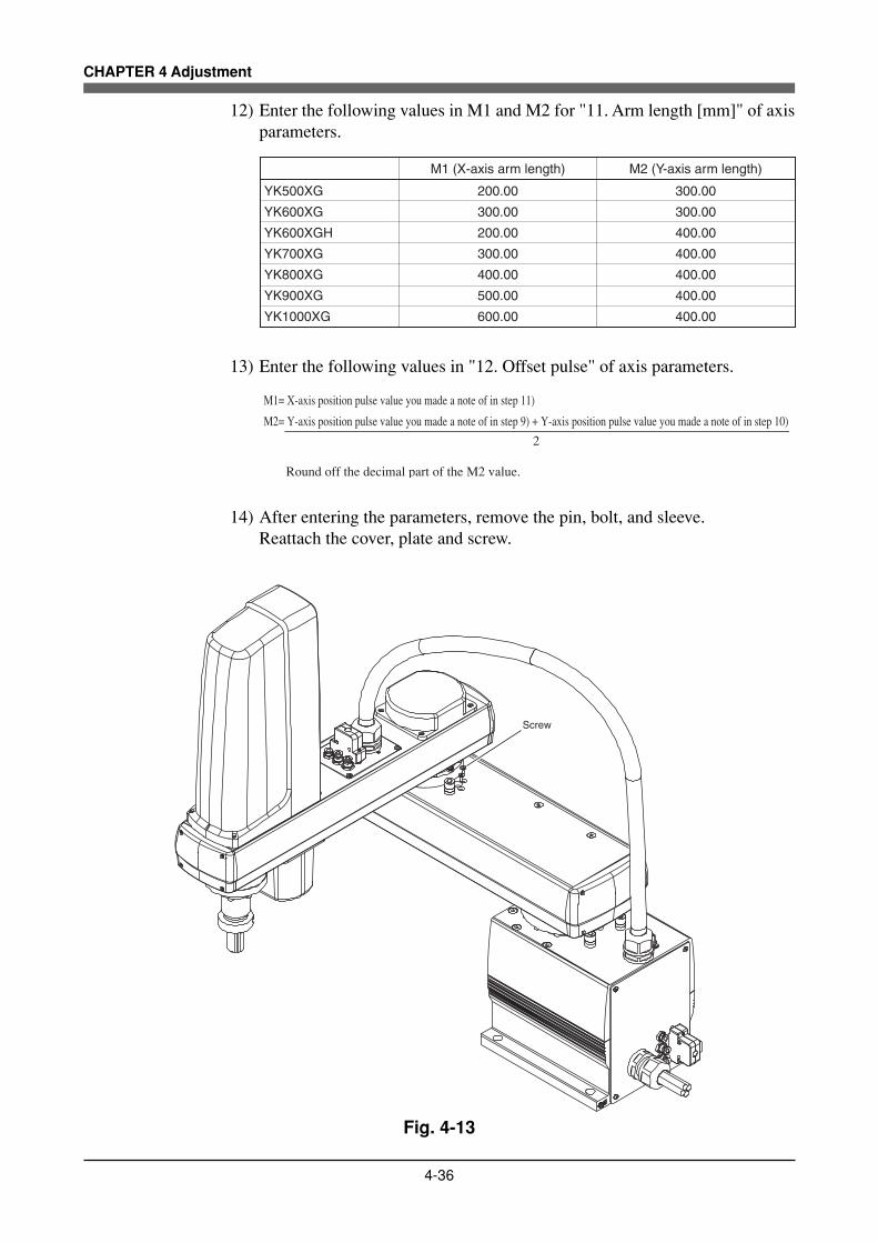
4-36
CHAPTER 4 Adjustment
12) Enter the following values in M1 and M2 for "11. Arm length [mm]" of axisparameters.
YK500XG
YK600XG
YK600XGH
YK700XG
YK800XG
YK900XG
YK1000XG
200.00
300.00
200.00
300.00
400.00
500.00
600.00
300.00
300.00
400.00
400.00
400.00
400.00
400.00
M1 (X-axis arm length) M2 (Y-axis arm length)
13) Enter the following values in "12. Offset pulse" of axis parameters.
M1= X-axis position pulse value you made a note of in step 11)
M2= Y-axis position pulse value you made a note of in step 9) + Y-axis position pulse value you made a note of in step 10)
Round off the decimal part of the M2 value.
2
14) After entering the parameters, remove the pin, bolt, and sleeve.Reattach the cover, plate and screw.
Screw
Fig. 4-13

4-37
CHAPTER 4 Adjustment
Bolt
Sleeve
Hole
Fig. 4-14
Bolt
Plate
Cover
Bolt
Fig. 4-15
Y-axis arm
Bolt
Pin
Sleeve
X-axis armElongated hole
Clockwise
Counterclockwise
Fig. 4-16

4-38
CHAPTER 4 Adjustment
6 Affixing the Stickers for Movement Directionsand Axis NamesThe robot comes packed with stickers showing origin positions, movement direc-tions and axis names as shown in Fig. 4-17. Using the following procedure, at-tach these stickers in conspicuous points on the robot after changing the originposition and installing peripheral equipment.
1) Check that no one is inside the safeguard enclosure, and then turn on thecontroller.
2) Move the robot to the 0 pulse position.To move the axes to their "0" pulse positions, see "Chapter 4 Point tracefunction" in the "YAMAHA Robot Controller User's Manual".
3) Turn off the controller.4) Place a sign indicating the robot is being adjusted, to keep others from oper-
ating the controller switch.5) Enter the safeguard enclosure.6) Being careful not to move the origin positions, attach stickers at conspicuous
points on matching sides of components such as the robot arm of each axis,base (robot pedestal) and end effector. Affix stickers nearby showing the axisname and direction of movement. Use a cloth moistened with alcohol to re-move grease from the surface where you will affix the stickers. After thesurface is dry, affix the stickers securely. (See Fig. 4-18)
WARNING
Affix the origin position stickers precisely on the origin positions. Align the direc-tion of movement stickers with the jog direction and affix them correctly. Affixeach axis name sticker on the correct axis. Affixing the sticker at a wrong loca-tion may cause faulty operation and hazardous situations.
A BX YZ R
(b) Direction of movement and axis name stickers
(a) Origin position stickers
Fig. 4-17

4-39
CHAPTER 4 Adjustment
R- +
End effector End effector
-+
Z
Y- +
X- +
Fig. 4-18

4-40
MEMO

CHAPTER 5
Periodic Inspecition
1 Overview ..........................................................................................................5-1
2 Precautions ......................................................................................................5-2
3 Daily Inspection ................................................................................................5-3
4 Six-Month Inspection........................................................................................5-5
5 Replacing the Harmonic Drive .........................................................................5-95-1 Replacement period ....................................................................................................... 5-9
5-2 Basic replacement procedure for harmonic drive and precautions .............................. 5-10
5-2-1 YK500XG, YK600XG, YK600XGH, YK700XG, YK800XG, YK900XG, YK1000XG ........ 5-12

MEMO

5-1
CHAPTER 5 Periodic Inspection
1 Overview
Daily and periodic inspection of the YAMAHA robot is essential in order to en-sure safe and efficient operation. This chapter describes the periodic inspectionitems and procedures for the YAMAHA YK-XG series robots.
Periodic inspection includes:• Daily inspection• 6-month inspection• Replacement of speed reduction gear (harmonic drive)
Make sure that you thoroughly understand details of the inspection and followthe procedures and precautions explained in this chapter.

5-2
CHAPTER 5 Periodic Inspection
2 Precautions
(1) Periodic inspection must be performed by or in the presence of personnelwho have received the Robot Training given by YAMAHA or YAMAHAdealers.
(2) Do not attempt any inspection, adjustment, repair and parts replacement notdescribed in this manual. This work requires specialized technical knowl-edge and skill, and may also involve work hazards.
(3) When inspection is required inside the safeguard enclosure, always turn offthe controller and also the external switch board.
(4) If the inspection or maintenance procedure calls for operation of the robot,stay outside the safeguard enclosure.
(5) Place a sign indicating the robot is being inspected, to keep others from oper-ating the controller switch, programming unit or operation panel.
(6) Use only the lubricants specified by YAMAHA or YAMAHA dealers.
(7) To check the operation after inspection, refer to "6 Trial operation" in Chapter 1.
WARNING
• When you need to touch the terminals or connectors on the outside of thecontroller during inspection, always first turn off the controller power switchand also the power source in order to prevent possible electrical shock.
• Never touch any internal parts of the controller.
For precautions on handling the controller, refer to the "YAMAHA Robot Con-troller User's Manual".

5-3
CHAPTER 5 Periodic Inspection
3 Daily Inspection
The following is an inspection list that must be performed every day before andafter operating the robot.
(1) Inspection to be performed with the controller turned off
1) Turn off the controller.2) Place a sign indicating the robot is being inspected, to keep others from
operating the controller switch.3) Enter the safeguard enclosure and check the following points.
Checkpoint Procedure
Machine harnessRobot cableUser cable and wiring
Check for scratches, dents and excessive bend and kinks. (If the machine harness or robot cable is damaged, contact YAMAHA dealer.)
Regulator, joints, air tube,solenoid valve, air cylinder
Check air pressure.Check for air leaks.Check drain.Check air filter for clogging or damage.
Robot exterior Check for damage. (If a damage is found, contact YAMAHA dealer.)
(2) Inspection to be performed with the controller turned on
1) Check that no one is inside the safeguard enclosure, and then turn on thecontroller.
2) Place a sign indicating the robot is being inspected, to keep others fromoperating the controller, programming unit or operation panel.
3) Check the following points from outside the safeguard enclosure.
Checkpoint Procedure
Safeguard enclosureCheck if the safeguard enclosure is in place.Check if emergency stop is triggered when the door is opened.Check if warning labels are affixed at the entrance and clearly visible.
Emergency stop device Press the emergency stop button to check if it works.
Robot movementCheck for abnormal movement and excessive vibration and noise. (If any abnormal symptom is found, contact YAMAHA dealer.)
Z-axis brake operation *1Check if the brake works to stop the Z-axis from dropping more than 3mm from the stationary point. (If any abnormal operation is found, contact YAMAHA dealer.)
*1 Visually check the Z-axis movement when you press the emergency stopbutton from outside the safeguard enclosure and also when you turn off thecontroller.

5-4
CHAPTER 5 Periodic Inspection
(3) Adjustment and parts replacement
1) After inspection, if you notice any adjustment or parts replacement isneeded, first turn off the controller and then enter the safeguard enclosureto perform the necessary work. After adjustment or replacement is fin-ished, again review the checkpoints outlined in (1) and (2) above.
2) If repair or parts replacement is required for the robot or controller, pleasecontact your YAMAHA dealer. This work requires specialized technicalknowledge and skill, so do not attempt it by yourself.

5-5
CHAPTER 5 Periodic Inspection
4 Six-Month InspectionTake the following precautions when performing 6-month inspection.
WARNINGThe Z-axis will slide down when the Z-axis brake is released, causing a hazard-ous situation. Do not release the brake when lubricating the Z-axis parts.
When lubricating the ball screw and spline shaft, observe the following precautions.
WARNINGPrecautions when handling grease:• Inflammation may occur if this gets in the eyes.
Before handling the grease, wear your safety goggles to ensure the greasewill not come in contact with the eyes.
• Inflammation may occur if the grease comes into contact with skin. Be sureto wear protective gloves to prevent contact with skin.
• Do not take orally or eat. (Eating will cause diarrhea and vomiting.)• Hands and fingers might be cut when opening the container, so use protec-
tive gloves.• Keep out of the reach of children.• Do not heat the grease or place near an open flame since this could lead to
sparks and fires.Emergency Treatment:• If this grease gets in the eyes, wash liberally with pure water for about 15
minutes and consult a physician for treatment.• If this grease comes in contact with the skin, wash away completely with
soap and water.• If taken internally, do not induce vomiting but promptly consult a physician for
treatment.Disposing of grease and the container:• Proper disposal is compulsory under federal, state and local regulations. Take
appropriate measures in compliance with legal regulations.• Do not pressurize the empty container. Pressurizing may cause the con-
tainer to rupture.• Do not attempt to weld, heat up, drill holes or cut this container. This might
cause the container to explode and the remaining materials inside it to ignite.
! CAUTIONUnless grease specified by YAMAHA is used, the service life of the ball screwand ball spline will shorten.
(1) Inspection to be performed with the controller turned off
1) Turn off the controller.
2) Place a sign showing that the robot is being inspected, to keep others fromoperating the controller switch.

5-6
CHAPTER 5 Periodic Inspection
3) Enter the safeguard enclosure and check the following points.
Checkpoint Procedure
Manipulator bolts and screws (Only for major bolts and screws exposed externally)
Grease lubrication of Z-axis ball screw and spline
Z-axis ball spline, ball screw
Controller
Detection areas of the origin sensors of the X-axis, Y-axis, and R-axis
Check for looseness and tighten if necessary.*1
Clean if it is dirty.
Check for looseness at each terminal and connector on the panel. (See 4 in Chapter 3.)
Lubricate the Z-axis spline shaft and ball screw nut after removing the old grease. The specified grease is Alvania S2 (SHOWA SHELL SEKIYU KK). (See Fig. 5-1.)
Check for backlash. (If any abnormality is found, contact YAMAHA dealer.)
*1 Bolt tightening torque
Bolt size Tightening torque (kgfcm) Tightening torque (Nm)
M3 button head bolt 14 1.4
M4 set screw 20 2.0
M3 20 2.0
M4 46 4.5
M5 92 9.0
M6 156 15.3
M8 380 37
M10 459 45.0
M12 1310 128
M14 2090 205
Use only YAMAHA genuine bolts or JIS B 1176 hex socket head bolts(strength class: JIS B 1051 12.9).

5-7
CHAPTER 5 Periodic Inspection
Cover
Supply grease through the grease nipple.
Apply grease to the groove.
Lower the spline and apply grease to the groove.
Fig. 5-1

5-8
CHAPTER 5 Periodic Inspection
(2) Inspection to be performed with the controller turned on
WARNING
• The robot controller must be installed outside the safeguard enclosure, toprevent a hazardous situation in which you or anyone enter the safeguardenclosure to inspect the controller while it is turned on.
• Bodily injury may occur from coming into contact with the fan while it is rotat-ing.
• When removing the fan cover for inspection, first turn off the controller andmake sure the fan has stopped.
1) Check that no one is inside the safeguard enclosure, and then turn on thecontroller.
2) Place a sign indicating the robot is being inspected, to keep others fromoperating the controller, programming unit or operation panel.
3) Check the following points from outside the safeguard enclosure.
Checkpoint Procedure
• Cooling fan at rear of controller
• Check if the fan rotates normally.• Check if objects blocking the fan are located and remove if any are found.• Check for abnormal noise from the rotating fan. If abnormal noise is heard, visually check and remove the cause. If no cause is found, contact YAMAHA dealer.• Check for dust on the fan cover. Remove and clean if necessary.
(3) Adjustment and parts replacement
1) After inspection, if you notice any adjustment or parts replacement isneeded, first turn off the controller and then enter the safeguard enclosureto perform the necessary work. After adjustment or replacement is fin-ished, again review the checkpoints outlined in (1) and (2) above.
2) If repair or parts replacement is required for the robot or controller, pleasecontact your YAMAHA dealer. This work requires specialized technicalknowledge and skill, so do not attempt it by yourself.

5-9
CHAPTER 5 Periodic Inspection
5 Replacing the Harmonic DriveThe YK-XG series robots listed in Table 5-1 use a harmonic drive as the speedreduction gear for the X, Y and R axes. Harmonic drives need to be replaced aftera specified operation time. Use the guideline explained below to determine thereplacement period and replace the harmonic drive periodically. Since the YK-XG series robots listed in Table 5-1 use long-life harmonic grease, it is not neces-sary to replace the harmonic grease.
5-1 Replacement periodThe harmonic drive replacement period is determined by the total number ofturns of the wave generator used in the harmonic drive. It is recommended toreplace the harmonic drive when the total number of turns has reached 8.4×10⁸
(at ambient operating temperatures of 0°C to +40°C). This means that the re-placement period will differ depending on the following operating conditions. Ifthe robot operation duty ratio is high or the robot is operated in environments athigher temperatures, the harmonic drive should be replaced earlier.
Replacement period = 8.4×10⁸/(n×60×h×D×N×θ) yearswhere n : Number of axis movements per minute
θ : Average turn per axis movementN : Speed reduction ratioh : Operation time per dayD : Operation days per year
For example, when the robot is used under the following conditions, the replacementperiod for the X-axis harmonic drive of the YK500XG can be calculated as follows.
n : 10θ : 0.25N : 80h : 24 hours per dayD : 240 days per year
Replacement period = 8.4×10⁸/(n×60×h×D×N×θ)= 8.4×10⁸/(10×60×24×240×80×0.25)= 12.2 years
Robot model
YK500XG, YK600XG
YK600XGH, YK700XG, YK800XG, YK900XG, YK1000XG
80
80
80
80
30
50
X-axis Y-axis R-axis
Table 5-1 Harmonic drive speed reduction ratio
Table 5-2 Bolt tightening torque
Bolt size Tightening torque (kgfcm) Tightening torque (Nm)
M3 button head bolt 14
20
1.4
M3 20 2.0
M4 46 4.5
M5 92 9.0
M6 156 15.3
M8 380 37
M10 720 71
M4 set screw 2.0
Recommended "Screw Lock": LOCTITE 262 (made by Henkel Corporation)Use only YAMAHA genuine bolts or JIS B 1176 hex socket head bolts(strength class: JIS B 1051 12.9).

5-10
CHAPTER 5 Periodic Inspection
5-2 Basic replacement procedure for harmonic drive and precautions
Basic procedures and precautions for replacing the harmonic drive are describedbelow. Before beginning the replacement work, always be sure to read these re-placement procedures and caution.
WARNING
• The motor and speed reduction gear casing are extremely hot after auto-matic operation, so burns may occur if these are touched. Before touchingthese parts, turn off the controller, wait for a while and check that the tem-perature has cooled.
• When removing the wave generator from the motor shaft or reinstalling itback onto the motor shaft, use caution to avoid as much as possible, apply-ing a thrust load to the motor shaft. If a load is applied, the resolver may bedamaged resulting in a hazardous situation of the robot trouble.
WARNING
Precautions when handling harmonic grease, cleaning oil:• Inflammation may occur if they get in the eyes.
Before handling them, wear your safety goggles to ensure they will not comein contact with the eyes.
• Inflammation may occur if they come into contact with skin. Be sure to wearprotective gloves to prevent contact with skin.
• Do not take orally or eat. (Eating will cause diarrhea and vomiting.)• Hands and fingers might be cut when opening the container, so use protec-
tive gloves.• Keep out of the reach of children.• Do not heat them or place near an open flame since this could lead to sparks
and fires.Emergency Treatment:• If they get in the eyes, wash liberally with pure water for about 15 minutes
and consult a physician for treatment.• If they come in contact with the skin, wash away completely with soap and
water.• If taken internally, do not induce vomiting but promptly consult a physician for
treatment.Disposing of harmonic grease, cleaning oil and the container:• Proper disposal is compulsory under federal, state and local regulations. Take
appropriate measures in compliance with legal regulations.• Do not pressurize the empty container. Pressurizing may cause the con-
tainer to rupture.• Do not attempt to weld, heat up, drill holes or cut this container. This might
cause the container to explode and the remaining materials inside it to ignite.
! CAUTION
The harmonic drive service life may shorten if the grease recommended byYAMAHA is not used.

5-11
CHAPTER 5 Periodic Inspection
Recommended grease
Use the following harmonic drive grease.4B No.2 (made by Harmonic Drive Systems Inc.)
! CAUTION
Harmonic drive• Do not apply strong shocks or impacts to these parts such as with a hammer.
Also, do not scratch, scar or dent these parts by dropping, etc. Such actionswill damage the harmonic drive.
• The specified performance cannot be maintained if any part of the harmonicdrive is used in a damaged state. This damage or wear may also lead totrouble with the harmonic drive.
• Since a positional shift occurs after replacing the harmonic drive, it is neces-sary to make absolute reset, standard coordinate setting and point data set-ting again.

5-12
CHAPTER 5 Periodic Inspection
5-2-1 YK500XG, YK600XG, YK600XGH, YK700XG, YK800XG,YK900XG, YK1000XG
The following steps describe procedures and precautions when replacing the har-monic drives of the YK500XG and YK600XG. (The illustrations show theYK500XG). For the bolt tightening torques in this work, refer to Table 5-2. Useonly YAMAHA genuine bolts or JIS B 1176 hex socket head bolts (strength class:JIS B 1051 12.9).
1. X-axis
1) Prepare the following tools and items.• Harmonic grease 4B No.2• Waste cloth (rag)• Phillips screwdriver• Hex wrench set• Screw Lock (thread sealant)• Ratchet handle• Hexagonal socket set• Torque wrench (with ratchet)• Replacement parts (See table below.)• Hexagon long bit
<YK500XG, YK600XG>For M6: installation diameter, 9.53 | outer diameter, 17 or less| 83 mm(approx.) at full length<YK600XGH to YK1000XG>For M5: installation diameter, 9.53 | outer diameter, 17 or less| 128mm(approx.) at full length
• Hexagon bit<YK500XG, YK600XG>For M4: installation diameter, 6.35<YK600 to YK1000XG>For M5: installation diameter, 9.53
Replacement parts
Parts name Type No. YAMAHA Parts No. Note
Harmonic drive SHG-25-80 KBF-M2110-000
q S90(JIS) KN4-M2143-000 Top of harmonic drive
O-ring w Rubber wire diameter 1.78mm × Ring inner diameter 66.4mm 90990-17J030 Base (robot pedestal)
e Rubber wire diameter 1.30mm × Ring inner diameter 66.50mm KN5-M257L-000 Supplied with harmonic drive
YK500XG, YK600XG
Replacement parts
Parts name Type No. YAMAHA Parts No. Note
Harmonic drive SHG-32-80 KBF-M2110-000
q S511(JIS) KN5-M2159-000 Top of harmonic drive
O-ring w Rubber wire diameter 1.50mm × Ring inner diameter 82.00mm 90990-17J035 Base (robot pedestal)
e Rubber wire diameter 1.50mm × Ring inner diameter 87.50mm KN5-M2199-000 Supplied with harmonic drive
YK600XGH, YK700XG, YK800XG, YK900XG, YK1000XG

5-13
CHAPTER 5 Periodic Inspection
2) Turn off the controller.
3) Place a sign indicating that the robot is being inspected, to keep others fromoperating the controller switch.
4) Enter the safeguard enclosure.
5) Remove the base front and rear covers. (See Fig. 5-2.)
6) Unplug the connectors on the X-axis motor power wire XM and resolverwire XP in the base. Also disconnect the X-axis motor ring-tongue terminal.
! CAUTION
Carefully remove the motor not to pinch fingers between the motor and thebase. An O-ring w is placed between the motor mating end face and the base.Replace this O-ring with a new one. (See Fig. 5-4 and Fig. 5-6.)On the YK600XGH and YK700XG to YK1000XG, an O-ring is placed betweenthe motor flange end face and the base.
7) Remove the bolts securing the motor by using a hexagon long bit and ratchethandle, while holding the motor not to let it drop (see Fig 5-3). Items inparentheses ( ) apply to the YK600XGH, and YK700XG to YK1000XG.
8) Pull the motor out of the base while turning the X-axis arm.
9) Remove the wave generator from the motor shaft.The wave generator is secured with a set screw (1 piece) and keyway (seeFig. 5-6). A spacer and bolts need to be removed for YK600XGH andYK700XG to YK1000XG.
! CAUTION
A spacer is inserted between the wave generator and the motor, so be carefulnot to lose it. No spacer is used there for the YK600XGH, and YK700XG toYK1000XG.
WARNING
• When you remove the X-axis arm installation bolts in the next step, the X-axis arm may come off causing a hazardous situation. Be especially carefulto keep the arm from falling when a heavy tool is attached to the arm tip. (SeeFig. 5-4.)
• Removing the X-axis arm is dangerous for just one person. Always use twoor more people, or remove the Y-axis arm in advance. Refer to "2. Y-axis" of"5-2-1" for removing the Y-axis arm.
10) Remove the X-axis arm installation bolts by using a hexagon bit and ratchethandle. (See Fig. 5-4).

5-14
CHAPTER 5 Periodic Inspection
11) Remove the X-axis arm and place it where it will not obstruct the work.
12) Remove the bolts securing the X-axis harmonic drive and also remove thepanhead bolt along with the nut. (See Fig. 5-5.)
13) Remove the X-axis harmonic drive from the X-axis arm.
! CAUTION
An O-ring q is fitted to the X-axis arm. Replace this O-ring with a new one.
14) Fit a new O-ring q coated with harmonic grease into the O-ring groove ofthe X-axis arm (See Fig. 5-5.). Grease to the O-ring is to prevent the O-ringfrom coming off, so a small amount is enough.Apply small amounts of "Screw Lock" to the bolts you removed earlier andtighten them to secure the new harmonic drive to the X-axis arm. Also returnthe panhead bolt and nut to the original position and secure them (See Fig. 5-5.). Apply small amounts of "Screw Lock" to the panhead bolt. See 1-2 in 3-4-1-1 for the panhead bolt tightening and tighten the bolt to the specifiedtorque.
! CAUTION
Do not allow the O-ring to get caught out of the groove during reassembly. Aproblem will occur if the robot is operated with the O-ring left caught out of thegroove.
15) Apply harmonic grease to the new wave generator and flexible spline.See Fig. 5-7 for applying grease properly.
16) Fit a new O-ring e coated with harmonic grease into the O-ring groove ofthe harmonic drive. Apply small amount of "Screw Lock" to the positioningbolts, then fix the harmonic drive to the base with 16 pieces of bolt by usinghexagon bit and torque wrench (see Fig. 5-5 and Fig. 5-7). Tighten the boltsto the specified torque.
! CAUTION
Do not allow the O-ring to get caught out of the groove during reassembly. Aproblem will occur if the robot is operated with the O-ring left caught out of thegroove.
17) Fit the spacer and wave generator onto the motor shaft, and fully insert themagainst the motor. Then, apply small amounts of "Screw Lock" to the setscrew (1 piece) you removed earlier and tighten it to secure the wave genera-tor onto the motor shaft (see Fig. 5-6). For 600XGH and YK700XG toYK1000XG, the wave generator need to be fixed with M5 bolts and spacersprior to this step.
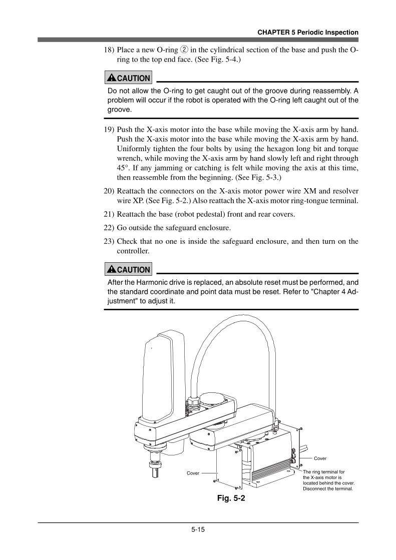
5-15
CHAPTER 5 Periodic Inspection
18) Place a new O-ring w in the cylindrical section of the base and push the O-ring to the top end face. (See Fig. 5-4.)
! CAUTION
Do not allow the O-ring to get caught out of the groove during reassembly. Aproblem will occur if the robot is operated with the O-ring left caught out of thegroove.
19) Push the X-axis motor into the base while moving the X-axis arm by hand.Push the X-axis motor into the base while moving the X-axis arm by hand.Uniformly tighten the four bolts by using the hexagon long bit and torquewrench, while moving the X-axis arm by hand slowly left and right through45°. If any jamming or catching is felt while moving the axis at this time,then reassemble from the beginning. (See Fig. 5-3.)
20) Reattach the connectors on the X-axis motor power wire XM and resolverwire XP. (See Fig. 5-2.) Also reattach the X-axis motor ring-tongue terminal.
21) Reattach the base (robot pedestal) front and rear covers.
22) Go outside the safeguard enclosure.
23) Check that no one is inside the safeguard enclosure, and then turn on thecontroller.
! CAUTION
After the Harmonic drive is replaced, an absolute reset must be performed, andthe standard coordinate and point data must be reset. Refer to "Chapter 4 Ad-justment" to adjust it.
Cover
Cover
The ring terminal for the X-axis motor is located behind the cover. Disconnect the terminal.
Fig. 5-2

5-16
CHAPTER 5 Periodic Inspection
M6×16(M5×16) X-axis motor
Base
Fig. 5-3

5-17
CHAPTER 5 Periodic Inspection
M4×18(M5×40)
O-ring w
YK500XG, YK600XG YK600XGH, YK700XG, YK800XG, YK900XG, YK1000XG
O-ring w
Fig. 5-4

5-18
CHAPTER 5 Periodic Inspection
O-ring q
Harmonic drive
O-ring e supplied with harmonic drive
M4×30 (M5×40)
M5 nut(M6 nut)
M4×30L (M5×40L) panhead bolt During reassembly, reattach this bolt to the same position on the X-axis arm as before.
Fig. 5-5
M4 setscrew(supplied with harmonic drive)
YK500XG, YK600XG YK600XGH, YK700XG, YK800XG, YK900XG, YK1000XG
M5×16 (YK600XG, YK700XG to YK1000XG only)
M4 setscrew(supplied with harmonic drive)
Wave generator(Harmonic drive) Wave generator
(Harmonic drive)
Spacer
Motor mating end face
Do not remove this spacer.
Motor flange end face Motor flange end face
Fig. 5-6

5-19
CHAPTER 5 Periodic Inspection
Apply grease to entire oldham coupling.
Fit O-ring (supplied) into this groove.
Never remove these temporarily tightened bolts. The axis will otherwise deviate from center.
Apply grease to entire inner surface to the thickness equal to ball diameter.
Flexible spline
Circular spline
Wave generator
Apply grease to sufficiently fill in the ball space.
Fig. 5-7

5-20
CHAPTER 5 Periodic Inspection
2. Y-axis
1) Prepare the following tools and items.• Harmonic grease 4B No.2• Waste cloth (rag)• Phillips screwdriver• Hex wrench set• Screw Lock (thread sealant)• Torque wrench• Replacement parts (See table below.)
Replacement parts
Parts name Type No. YAMAHA Parts No. Note
Harmonic drive SHG-20-80 KBF-M2510-000
q Rubber wire diameter 1.78mm × Ring inner diameter 72.75mm KN4-M257K-000 Lower part of harmonic drive
O-ring w Rubber wire diameter 1.50mm × Ring inner diameter 49.00mm KN3-M2143-000 For motor
e Rubber wire diameter 0.99mm × Ring inner diameter 53.28mm KN3-M2144-000 Supplied with harmonic drive
YK500XG, YK600XG
Replacement parts
Parts name Type No. YAMAHA Parts No. Note
Harmonic drive SHG-25-80 KBP-M2510-000
q S90(JIS) KN4-M2143-000 Lower part of harmonic drive
O-ring w Rubber wire diameter 1.78mm × Ring inner diameter 66.40mm 90990-17J030 For motor
e Rubber wire diameter 1.3mm × Ring inner diameter 66.50mm KN5-M257L-000 Supplied with harmonic drive
YK600XGH, YK700XG, YK800XG, YK900XG, YK1000XG
2) Turn off the controller.
3) Place a sign indicating that the robot is being inspected, to keep others fromoperating the controller switch.
4) Enter the safeguard enclosure.
5) Remove the cover. (See Fig. 5-8.)
6) Unplug the connectors on the Y-axis motor power wire YM and resolver wireYP in the Y-axis arm. Also disconnect the Y-axis motor ring-tongue terminal.
7) Remove the bolts securing the Y-axis motor, and slowly pull out the Y-axismotor while turning the Y-axis joint. (See Fig. 5-9.)Items in parentheses ( ) apply to the YK600XGH and YK700XG toYK1000XG.
! CAUTION
An O-ring w is fitted to the motor. Replace this O-ring with a new one.(See Fig. 5-12.)

5-21
CHAPTER 5 Periodic Inspection
8) Remove the wave generator from the motor shaft. The wave generator issecured with a set screw (1 piece) and keyway. (See Fig. 5-12.)
WARNING
When you remove the Y-axis arm installation bolts in the next step, the Y-axisarm may come off causing a hazardous situation. Be especially careful to keepthe arm from falling when a heavy tool is attached to the arm tip.(See Fig. 5-10.)
9) Remove the Y-axis arm installation bolts. (See Fig. 5-10.)
10) Remove the Y-axis arm and place it where it will not obstruct the work.
! CAUTION
An O-ring e is fitted to the upper surface of the harmonic drive, so be carefulnot to let it drop into the peripheral unit. (See Fig. 5-11.)
11) Remove the bolts securing the Y-axis harmonic drive and also remove thepanhead bolt along with the nut. (See Fig. 5-11.)
12) Remove the Y-axis harmonic drive from the top of the X-axis arm.
! CAUTION
An O-ring q is fitted to the upper surface of the X-axis arm. Replace this O-ringwith a new one.
13) Fit a new O-ring q coated with harmonic grease into the O-ring groove ofthe X-axis arm. (See Fig. 5-11.)
14) Place the new harmonic drive on the X-axis arm and secure it with the boltsyou removed earlier. At this point, apply small amounts of "Screw Lock" tothose bolts and uniformly tighten them. Also return the panhead bolt and nutto the original position and secure them. Apply small amounts of "ScrewLock" to the panhead bolt. See 2-2 in 3-4-1-1 for the panhead bolt tighteningand tighten the bolt to the specified torque.
! CAUTION
Do not allow the O-ring to get caught out of the groove during reassembly. Aproblem will occur if the robot is operated with the O-ring left caught out of thegroove.
15) Fit a new O-ring e coated with harmonic grease into the O-ring groove ofthe harmonic drive. (Fig. 5-11.)
5-22
CHAPTER 5 Periodic Inspection
16) Secure the Y-axis arm to the harmonic drive with the bolts you removed earlier.At this time keep the Y-axis arm level by two people so as not to apply amoment to the Y-axis. One person supports the tip of the Y-axis arm. Theother person secures the Y-axis arm.Apply small amounts of "Screw Lock" to the 16 bolts and tighten them uni-formly to secure the Y-axis arm. (See Fig. 5-10.) Tighten the bolts to thespecified torque.
! CAUTION
Do not allow the O-ring to get caught out of the groove during reassembly. Aproblem will occur if the robot is operated with the O-ring left caught out of thegroove.
17) Apply harmonic grease to the new wave generator and flexible spline.See Fig. 5-7 for applying grease properly.
18) Fit the wave generator onto the motor shaft, and fully insert it against themotor. Then, apply small amounts of "Screw Lock" to the set screw (1 piece)you removed earlier and tighten it to secure the wave generator (See Fig. 5-12.). On the YK600XGH and YK700XG to YK1000XG, do not forget toinsert a spacer.
19) Fit a new O-ring w to the motor and place the motor in the Y-axis arm whileturning the Y-axis joint. Then tighten the bolts you removed earlier totemporarily secure the motor to the Y-axis arm. (See Fig. 5-9.)On the YK600XGH and YK700XG to YK1000XG, fit the new O-ring w intothe groove in the Y-axis arm. (See Fig. 5-12.)
! CAUTION
Do not allow the O-ring to get caught out of the groove during reassembly. Aproblem will occur if the robot is operated with the O-ring left caught out ofgroove.
20) Uniformly tighten the four bolts temporarily fastened in the previous stepwhile turning the Y-axis joint. If any jamming or catching is felt at this time,then reassemble from the beginning.
21) Reattach the connectors on the Y-axis motor power wire YM and resolverwire YP. (See Fig. 5-8.) Also reattach the Y-axis motor ring-tongue terminal.
22) Reattach the cover.
23) Go outside the safeguard enclosure.
24) Check that no one is inside the safeguard enclosure, and then turn on thecontroller.
! CAUTION
After the Harmonic drive is replaced, an absolute reset must be performed, andthe standard coordinate and point data must be reset. Refer to "Chapter 4 Ad-justment" to adjust it.

5-23
CHAPTER 5 Periodic Inspection
Cover
Cover
Y-axis arm
Disconnect this Y-axis motor ring-tongue terminal located inside the cover.
Fig. 5-8
M5×12 (M6×16)
Y-axis motor
Fig. 5-9

5-24
CHAPTER 5 Periodic Inspection
M3×16 (M4×18)
X-axis arm
Fig. 5-10

5-25
CHAPTER 5 Periodic Inspection
O-ring e
Harmonic drive
M3×30 (M4×30)
M3×30L (M4×30L) panhead boltDuring reassembly, reattach this bolt to the same position on the X-axis arm as before.
M4 nut (M5 nut)
O-ring q
Fig. 5-11
M3 setscrew(supplied with harmonic drive)
Wave generator(Harmonic drive)
O-ring w
YK500XG, YK600XG
Fig. 5-12
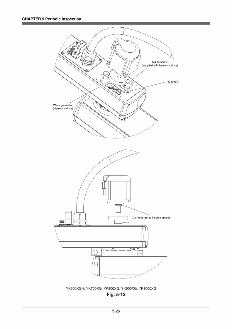
5-26
CHAPTER 5 Periodic Inspection
M4 setscrew(supplied with harmonic drive)
O-ring w
Wave generator(Harmonic drive)
Do not forget to insert a spacer.
YK600XGH, YK700XG, YK800XG, YK900XG, YK1000XG
Fig. 5-12

5-27
CHAPTER 5 Periodic Inspection
3. R-axis
1) Prepare the following tools and items.• Harmonic grease 4B No.2• Waste cloth (rag)• Phillips screwdriver• Hex wrench set• Screw Lock (thread sealant)• Torque wrench• Hook wrench• Replacement parts (See table below.)
Replacement parts
Parts name Type No. YAMAHA Parts No. Note
Harmonic drive
Edge seal
SHF-17-30 KBF-M1821-000
Lower part of harmonic drive
O-ring
q Rubber wire diameter 1.78mm × Ring inner diameter 63.22mm KN4-M1896-000
w Rubber wire diameter 0.80mm × Ring inner diameter 45.40mm
V-25A (N+C)
KN3-M257L-000
KBF-M1886-000
Supplied with harmonic drive
e Rubber wire diameter 1.00mm × Ring inner diameter 35.3mm 90990-17J031 Spline nut
r Rubber wire diameter 1.00mm × Ring inner diameter 46.00mm 90990-17J032 Y-axis arm
t Rubber wire diameter 0.60mm × Ring inner diameter 22.00mm 90990-17J033 Wave generator
FORSHEDA
YK500XG, YK600XG
Replacement parts
Parts name Type No. YAMAHA Parts No. Note
Harmonic drive
Edge seal
SHF-20-50 KBP-M1821-000
Lower part of harmonic drive
O-ring
q S71(JIS) KN3-M2159-000
w Rubber wire diameter 0.99mm × Ring inner diameter 53.28mm
V-28A (N+C)
KN3-M2144-000
KBP-M1886-000
Supplied with harmonic drive
e Rubber wire diameter 1.00mm × Ring inner diameter 43.00mm 90990-17J036 Spline nut
r Rubber wire diameter 1.30mm × Ring inner diameter 53.00mm 90990-17J038 Y-axis arm
t Rubber wire diameter 0.5mm × Ring inner diameter 28.00mm 90990-17J037 Wave generator
FORSHEDA
YK600XGH, YK700XG, YK800XG, YK900XG, YK1000XG
2) Turn off the controller.
3) Place a sign indicating that the robot is being inspected, to keep others fromoperating the controller switch.
4) Enter the safeguard enclosure.
5) Remove the cover. (See Fig. 5-13.)Unplug the connectors on the R-axis motor power wire RM and resolverwire RP in the Y-axis arm. Also disconnect the R-axis motor ring-tongueterminal.
WARNING
The Z-axis will slide down when the bearing mounting bolts are removed in thenext step, causing a hazardous situation. Prop the Z-axis with a support standbefore loosening these bolts. (See Fig. 5-14.)

5-28
CHAPTER 5 Periodic Inspection
6) Remove the bolts securing the bearing to the upper end of the spline andremove the spline and bearing from the holder. (See Fig. 5-14.)
7) Fit the spanner or wrench to the flat surfaces at the bottom of the spline togrip it, and loosen and remove the U-nut on top of the spline with the hookspanner. Then remove the bearing and bearing mount plate. (See Figs. 5-15and 5-16.)At this point, be careful to keep the spline shaft from coming off the splinenut.
8) Remove the bolts securing the spline nut and remove the spline nut.(See Fig. 5-16.)
! CAUTION
An O-ring e is fitted to the shaft. Replace this O-ring with a new one. Alsoreplace the V-ring with a new one. Do not remove the sleeve. (See Fig. 5-16.)
9) Remove the bolts securing the R-axis motor and pull out the R-axis motorwhile turning the R-axis. (See Fig. 5-17.)
! CAUTION
An O-ring r is placed between the R-axis motor flange and the Y-axis arm.Replace this O-ring with a new one. (See Fig. 5-17.)
10) Loosen the two setscrews for the wave generator.Pull the wave generator out of the R-axis motor shaft. (See Fig. 5-20.)
! CAUTION
An O-ring t is placed between the R-axis motor shaft and the wave generator.Replace this O-ring with a new one. (See Fig. 5-20.)
11) Remove the bolts securing the harmonic drive and remove the harmonic drive.(See Fig. 5-18.)
! CAUTION
An O-ring w is fitted to the harmonic drive. Replace this O-ring with a new one.(See Fig. 5-18.)
12) Remove the shaft mounting bolts from the harmonic drive and also removethe panhead bolt along with the nut. Then remove the shaft.On the YK600XGH and YK700XG to YK1000XG, remove the dog and bolt.(See Fig. 5-19 (b).)
! CAUTION
An O-ring q is placed between the harmonic drive and shaft. Replace this O-ring with a new one. (See Fig. 5-19 (a) (b).)

5-29
CHAPTER 5 Periodic Inspection
13) Apply the harmonic grease to the new wave generator. See Fig. 5-21 forapplying the grease.
14) Fit the O-ring t to the inner side of the new wave generator. Insert the wavegenerator into the inner end of the R-axis motor shaft and secure it with thetwo setscrews. (See Fig. 5-20.)
15) Apply harmonic grease to the circular spline.See Fig. 5-21 for applying grease properly.
16) Fit a new O-ring q coated with harmonic grease into the groove of the shaft.Apply small amounts of "Screw Lock" to the bolts you removed earlier andtighten them to secure the new harmonic drive. Also return the panhead boltand nut to the original position and secure them. Apply small amounts of"Screw Lock" to the panhead bolt. The panhead bolt tightening torque shouldbe 90cNm (9kgfcm). On the YK600XGH and YK700XG to YK1000XG,also apply "Screw Lock" to the dog mounting bolt and tighten it to a torqueof 2.0Nm (20kgfcm). (See Fig. 5-19 (b).)
! CAUTION
Do not allow the O-ring to get caught out of the groove during reassembly. Aproblem will occur if the robot is operated with the O-ring left caught out ofgroove.
17) Fit the O-ring w coated with harmonic grease into the O-ring groove of thenew harmonic drive. (See Fig. 5-18.)Apply small amounts of "Screw Lock" to the bolts you removed earlier andtighten them to secure the new harmonic drive to the Y-axis arm from the topof the Y-axis arm. (See Fig. 5-18.)
! CAUTION
Do not allow the O-ring to get caught out of the groove during reassembly. Aproblem will occur if the robot is operated with the O-ring left caught out ofgroove.
18) Fit the new O-ring r coated with harmonic grease into the O-ring groove ofthe Y-axis arm.Insert the R-axis motor into the Y-axis arm while turning the R-axis. Thentighten the bolts to secure the R-axis motor while turning the R-axis. (SeeFig. 5-17.)
! CAUTION
Do not allow the O-ring to get caught out of the groove during reassembly. Aproblem will occur if the robot is operated with the O-ring left caught out ofgroove.

5-30
CHAPTER 5 Periodic Inspection
19) Fit the new O-ring e coated with harmonic grease into the groove at thebottom of the shaft. Attach a new V-ring to the top of the sleeve and securethe spline nut to the shaft with the bolts you removed earlier. (See Fig. 5-16.)
! CAUTION
Do not allow the O-ring to get caught out of the groove during reassembly. Aproblem will occur if the robot is operated with the O-ring left caught out ofgroove.
20) Insert the bearing mount plate and bearing onto the spline from the top, andtighten the U-nut to secure the bearing. (Utilize the flat surfaces whentightening the U-nut like you did to loosen it.) On the YK600XGH andYK700XG to YK1000XG, do not forget to insert a spacer. (See Fig. 5-15.)
21) Insert the spline and bearing through the holder and secure them with thebolts you removed earlier. (See Fig. 5-14.)
22) Reconnect the R-axis motor power wire RM and resolver wire RP.Also reconnect the R-axis motor ring-tongue terminal.
23) Reattach the cover.
24) Go outside the safeguard enclosure.
25) Check that no one is inside the safeguard enclosure, and then turn on thecontroller.
! CAUTION
After the Harmonic drive is replaced, the absolute reset must be performed,and the point data must be reset. Refer to "Chapter 4 Adjustment" to adjust it.

5-31
CHAPTER 5 Periodic Inspection
Cover
Disconnect this R-axis motor ring-tongue terminal located inside the cover.
Cover
Fig. 5-13
M5×14
Bearing mount plate
Holder
Spline
Fig. 5-14

5-32
CHAPTER 5 Periodic Inspection
Bearing mount plate
Bearing
U-nut
U-nut
Spacer
Bearing
Flat surface
Bearing mount plate
M5×14
Flat surface
YK500XG, YK600XG YK600XGH, YK700XG, YK800XG, YK900XG, YK1000XG
Fig. 5-15
V-ringDegrease and make it tight contact with sleeve.
SleeveDo not remove this sleeve from spline nut.
Spline nut
Shaft
O-ring e
M4×10(M5×14)
Fig. 5-16

5-33
CHAPTER 5 Periodic Inspection
O-ring r
M5×14(M6×16)
R-axis motor
Fig. 5-17

5-34
CHAPTER 5 Periodic Inspection
M3×14(M3×16)
O-ring w
Fig. 5-18

5-35
CHAPTER 5 Periodic Inspection
M4 nut
M3×30L panhead bolt
M3×25
O-ring w
Harmonic drive
Shaft
O-ring q
YK500XG, YK600XG
Fig. 5-19 (a)

5-36
CHAPTER 5 Periodic Inspection
M3×30
Shaft
O-ring q
Harmonic drive
O-ring w
M3×25
Dog
YK600XGH, YK700XG, YK800XG, YK900XG, YK1000XG
Fig. 5-19 (b)

5-37
CHAPTER 5 Periodic Inspection
R-axis motor
O-ring t
Wave generator(Harmonic drive)
M4 setscrew(M3 set screw)(supplied with harmonic drive)
Tightening torqueYK500XG, YK600XG: 7kgfcm (0.7Nm)YK600XGH to YK1000XG: 17kgfcm (1.7Nm)
Fig. 5-20

5-38
CHAPTER 5 Periodic Inspection
Wave generator ball• Apply grease to fill the space around the ball.
Apply grease only to ball parts.
Do not apply grease thicker than 0.5mm to the area above the end face seal lip.
End face seal lip• Apply slight amount of grease to the lip only.• Remove all grease that remain inside the lip.
Harmonic grease• Apply grease every around.• Be cautious about the amount of grease; amounts of the grease applying to the area above and below the end face seal lip are different.
Below the end face seal lip, apply grease as thick as the diameter of the wave generator ball.
Fig. 5-21

CHAPTER 6
Increasing the robotoperating speed
1 Increasing the Robot Operating Speed ............................................................6-1

MEMO

6-1
CHAPTER 6 Increasing the robot operating speed
1 Increasing the Robot Operating Speed
The robot operating speed can be increased by the following methods. Use thesemethods as needed when programming.
(1) Increasing speed by arch motion[Also refer to:] Robot controller user's manual
("Axis parameters" – "Arch position" in Chapter 4)Programming manual(ARCH statement in "11. Command statements".)
q Gate motionFrom point P1 to P4 via P2 and P3:MOVE P, P2MOVE P, P3MOVE P, P 4
w Arch motion: Using default arch position: (2000 pulses)From point P1 to P2:MOVE P, P2, Z=0
"Axis parameters" – "Arch position"M1 (X-axis arch position) = 2000 pulsesM2 (Y-axis arch position) = 2000 pulsesM3 (Z-axis arch position) = 2000 pulsesM4 (R-axis arch position) = 2000 pulses
When the Z-axis moves upward from P1 and enters the M3 arch position range(2000 pulses prior to Z=0), the X, Y and R axes begin to move. When these 3 axesenter the M1, M2 and M4 arch position range (2000 pulses prior to P2), the Z-axis moves downward to P2. Compared with the gate motion q, this arch motionshortens the cycle time approximately 20% by moving the robot arm along anarc.
Z=0 P2
P1
P3
P4
Z=0
M1, M2, M4
P1
M3
P2
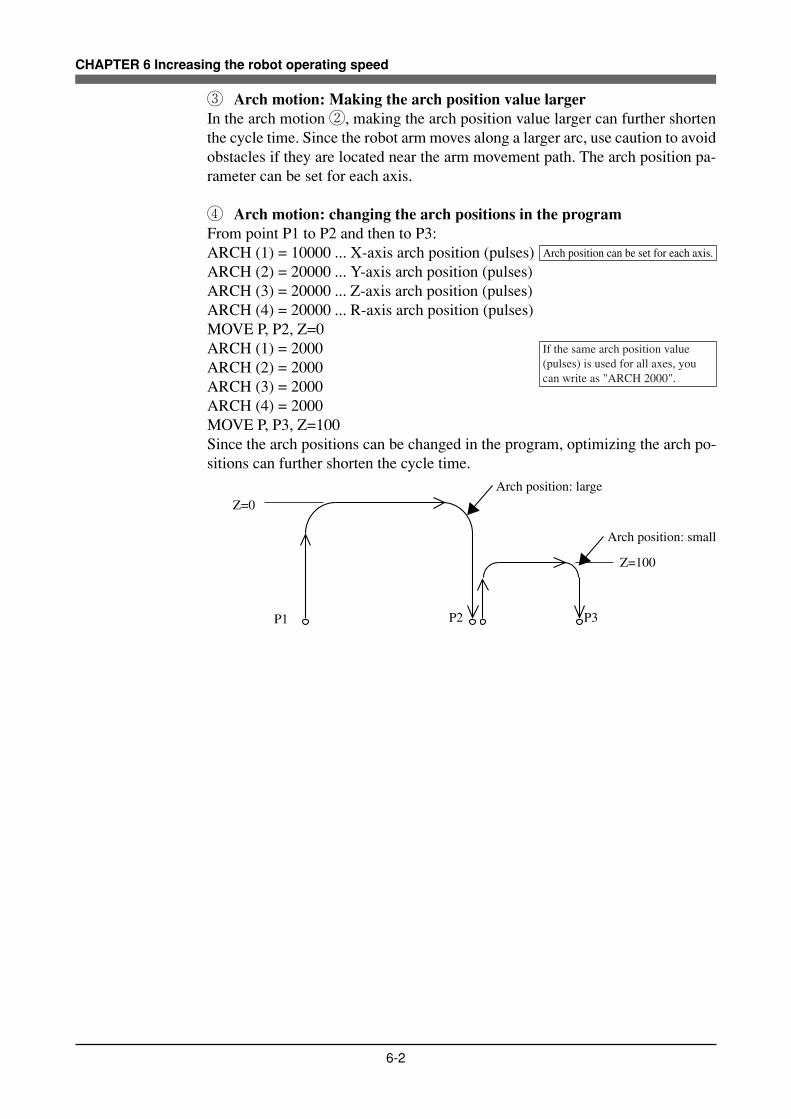
6-2
CHAPTER 6 Increasing the robot operating speed
e Arch motion: Making the arch position value largerIn the arch motion w, making the arch position value larger can further shortenthe cycle time. Since the robot arm moves along a larger arc, use caution to avoidobstacles if they are located near the arm movement path. The arch position pa-rameter can be set for each axis.
r Arch motion: changing the arch positions in the programFrom point P1 to P2 and then to P3:ARCH (1) = 10000 ... X-axis arch position (pulses)ARCH (2) = 20000 ... Y-axis arch position (pulses)ARCH (3) = 20000 ... Z-axis arch position (pulses)ARCH (4) = 20000 ... R-axis arch position (pulses)MOVE P, P2, Z=0ARCH (1) = 2000ARCH (2) = 2000ARCH (3) = 2000ARCH (4) = 2000MOVE P, P3, Z=100Since the arch positions can be changed in the program, optimizing the arch po-sitions can further shorten the cycle time.
Z=0
P1 P2 P3
Z=100
Arch position: large
Arch position: small
Arch position can be set for each axis.
If the same arch position value (pulses) is used for all axes, you can write as "ARCH 2000".

6-3
CHAPTER 6 Increasing the robot operating speed
(2) Increasing the speed with the WEIGHT statement[Also refer to:] Robot controller user's manual
("Robot parameters" – "Axis tip weight" in Chapter 4)Programming manual(WEIGHT statement in "11. Command statements".)
[Example]From P1 when chuck is open:WEIGHT 5 ........Changes the axis tip weight parameter to 5kg (no workpiece).MOVE P, P2, Z=0DO3 (0) = 1 .......Chuck closes.WEIGHT 10 ......Changes the axis tip weight parameter to 10kg (with workpiece).MOVE P, P3, Z=0
In the above program, the acceleration can be set to a higher level by reducing theaxis tip weight parameter to 5kg while the chuck does not grip any workpiece,and then set to a lower level by changing the axis tip weight parameter to 10kg.Compared to programs using an axis tip weight parameter left set at 10kg, thismethod shortens the cycle time since the acceleration is increased.
P1
Z=0
Chuck opens.
Chuck 5kg
Workpiece 5kg
P3P2Chuck closes.
No workpiece Chuck is gripping workpiece.

6-4
CHAPTER 6 Increasing the robot operating speed
(3) Increasing the speed by the tolerance parameter[Also refer to:] Robot controller user's manual
("Axis parameters" – "Tolerance" in Chapter 4)Programming manual(TOLE statement in "11. Command statements".)
[Example]From P1 to P3 via P2TOLE (1) = 2048 ... X-axis tolerance (pulses) : Increases the tolerance.TOLE (2) = 2048 ... Y-axis tolerance (pulses)TOLE (3) = 2048 ... Z-axis tolerance (pulses)TOLE (4) = 2048 ... R-axis tolerance (pulses)MOVE P, P2TOLE (1) = 80 ....... Returns the tolerance to the default value.TOLE (2) = 80TOLE (3) = 80TOLE (4) = 80MOVE, P, P3
When P2 is an escape point and does not need to be accurately positioned, settingthe tolerance parameter to a larger value allows the robot arm to pass through P2quickly. The larger the tolerance value for the positioning time, the shorter thecycle time will be. The maximum value of the tolerance parameter is 2048 (pulses)and the default is 80 (pulses).
P1
P2
P3
Tolerance can be set for each axis.If the same tolerance is used for all axes, you can write as "TOLE 2048".
If the same tolerance is used for all axes, you can write as "TOLE 80".

6-5
CHAPTER 6 Increasing the robot operating speed
(4) Increasing the speed by the OUT effective position parameter[Also refer to:] Robot controller user's manual
("Axis parameters" – "Out effective Position" in Chapter 4)Programming manual(OUTPOS statement in "11. Command statements".)
[Example]From P1 when chuck is open:OUTPOS (1) = 10000 ... X-axis OUT effective position (pulses) : Increases the OUT effective position.OUTPOS (2) = 10000 ... Y-axis OUT effective position (pulses)OUTPOS (3) = 10000 ... Z-axis OUT effective position (pulses)OUTPOS (4) = 10000 ... R-axis OUT effective position (pulses)MOVE P, P2, Z=0DO3 (0) = 1 .................. Chuck closes.OUTPOS (1) = 2000 ..... Returns the OUT effective position to the default value.OUTPOS (2) = 2000OUTPOS (3) = 2000OUTPOS (4) = 2000
P1 P2Chuck closed.
Chuck starts closing.
OUT effective position
When all of the X, Y, Z and R axes enter the OUT effective position (10000pulses prior to P2), the chuck starts closing. By setting the OUT effective posi-tion larger, the chuck starts closing while the robot arm is still moving at anearlier point, so that the chuck can grip the workpiece more quickly. The defaultvalue of the OUT effective position is 2000 (pulses).
[Reference]Relation between X, Y, R-axis rotating angle, Z-axis movement distance and pulse valuesThe arch position, tolerance and OUT effective position parameters are set inpulses. For the relation between X, Y, R-axis rotating angle, Z-axis movementdistance and pulse values, refer to the tables listed under item (4) in "4. Settingthe soft limits". (Chapter 4 in this manual)
The OUT effective position can be set for each axis.If the same OUT effective position is used for all axes, you can write as "OUTPOS 10000".
If the same OUT effective position is used for all axes, you can write as "OUTPOS 2000".

6-6
MEMO

CHAPTER 7
Specifications
1 Manipulator ......................................................................................................7-11-1 Basic specification .......................................................................................................... 7-1
1-2 External view and dimensions ........................................................................................ 7-2
1-3 Robot inner wiring diagram........................................................................................... 7-16
1-4 Wiring table................................................................................................................... 7-17

MEMO

7-1
CHAPTER 7 Specifications
1 Manipulator
1-1 Basic specification
YK500XG
200mm
±130°300mm
±145°200, 300mm
±360°400W
200W
200W
200W
7.6m/s
1700°/s
2.3m/s (200mm stroke Z-axis)1.7m/s (300mm stroke Z-axis)
30kg 31kg
YK600XG
300mm
±130°300mm
±145°200, 300mm
±360°400W
200W
200W
200W
8.4m/s
1700°/s
Arm length
Rotation angle
Arm length
Rotation angle
Stroke
Rotation angle
X-axis
Y-axis
Z-axis
R-axis
XY resultant
Z-axis
R-axis
X-axis
Y-axis
Z-axis
R-axis
Axis specifi-
cations
Motor
Maximum
speed
1.Soft limit 2.Mechanical stopper (XYZ-axes)
3.5m (option: 5m, 10m)
Robot model Robot model
*1 At constant ambient temperature (XY)*2 There are limits to acceleration coefficient settings.
10kg
0.30kgm2 (3.0kgfcms2)
20 cables
φ6×3
YK500XG
±0.01mm
±0.01mm
±0.004°
YK600XG
±0.01mm
±0.01mm
±0.004°
Repeatability *1
Payload
R-axis tolerable moment of inertia *2
User wiring
User tubing
Travel limit
Robot cable
Weight
XY-axes
Z-axis
R-axis
YK600XGH
200mm
±130°400mm
±150°200, 400mm
±360°750W
400W
400W
200W
7.7m/s
920°/s
±0.02mm
±0.01mm
±0.004°
2.3m/s (200mm stroke Z-axis)1.7m/s (400mm stroke Z-axis)
48kg, 50kg 50kg, 52kg 52kg, 54kg 54kg, 56kg 56kg, 58kg
YK700XG
300mm
±130°400mm
±150°200, 400mm
±360°750W
400W
400W
200W
8.4m/s
920°/s
±0.02mm
±0.01mm
±0.004°
YK800XG
400mm
±130°400mm
±150°200, 400mm
±360°750W
400W
400W
200W
9.2m/s
920°/s
±0.02mm
±0.01mm
±0.004°
YK900XG
500mm
±130°400mm
±150°200, 400mm
±360°750W
400W
400W
200W
9.9m/s
920°/s
±0.02mm
±0.01mm
±0.004°
YK1000XG
600mm
±130°400mm
±150°200, 400mm
±360°750W
400W
400W
200W
10.6m/s
920°/s
±0.02mm
±0.01mm
±0.004°
1.Soft limit 2.Mechanical stopper (XYZ-axes)
3.5m (option: 5m, 10m)
*1 At constant ambient temperature (XY)*2 There are limits to acceleration coefficient settings.
20kg
1.0kgm2 (10.0kgfcms2)
20 cables
φ6×3
Arm length
Rotation angle
Arm length
Rotation angle
Stroke
Rotation angle
X-axis
Y-axis
Z-axis
R-axis
XY resultant
Z-axis
R-axis
XY-axes
Z-axis
R-axis
X-axis
Y-axis
Z-axis
R-axis
Robot model
Axis specifi-cations
Motor
Maximum speed
Repeatability *1
Payload
R-axis tolerable moment of inertia *2
User wiring
User tubing
Travel limit
Robot cable
Weight
Maximum sound pressure level of the robot (when there is 10dB or larger difference from the back ground sound pressure level)
Position where the maximum sound pressure is measured
1 meter apart from the back of the robot, 1.6m height from the floor surface.
Note: The noise level can be higher when the robot is set nearby the objects that cause sound reflection.
Noise level
78.4dB

7-2
CHAPTER 7 Specifications
1-2 External view and dimensions
Z200mm stroke
Z300mm stroke
11354
60 140
40 120
200300 19471
120
200 (Base size)
150
178
7979
675
775
100
D-sub connector for user wiring (No. 1 to 20 usable)
200
Z-ax
is st
roke
300
Z-ax
is s
troke
10
10
0
158.5
187
259
373
652(Maximum 660 during arm rotation)
0
137.6±2
204
253
283
351
213
242
User toolinstallation range 8m
m ris
e dur
ing Z
-axis
retur
n-to-
origi
n
Flat surface has no phase relation to R-axis origin.
0-0.021
1440
Cross section A-A
Widt
h ac
ross
flat 1
9
Hollow diameter φ14
71
Z-axis lower endmechanical stopper position
3210
4040
89
81
AA A
User tubing 1 (φ6 black)
User tubing 2 (φ6 red)
User tubing 3 (φ6 blue)4-φ11 M10 bolt for installation, 4bolts used
φ50
φ20h7
4-M4x0.7 through-hole for tool attachmentFour M4x10L binding screws are supplied.Do not screw the screws in deeper than 10mm from bottom surface of arm.
M16x2 Depth 20 (Bottom of spline)
Fig. 7-1 YK500XG

7-3
CHAPTER 7 Specifications
Working envelope of left-handed system
130°
130°
145°
260
50144
165
R300
R178
R25R300
R500
114°
145°
130° 130°
165
260
50
144R30
0
R25
R500
R178
114°
Working envelope of right-handed system
X-axis mechanical stopper position: 132°Y-axis mechanical stopper position: 147°
R300
39 40M4 ground terminal
D-sub connector for user wiring(No. 1 to 20 usable)
015274767
04046
User tubing 1 (φ6 black)
User tubing 2 (φ6 red)
User tubing 3 (φ6 blue)

7-4
CHAPTER 7 Specifications
60 140
40 120
300300 19471
120
200 (Base size)
178
7979
100
D-sub connector for user wiring (No. 1 to 20 usable)
150
Z200mm stroke
Z300mm stroke
11354
137.6±2
204213
242253
283
351
675
775
10
10
0
User toolinstallation range
200
Z-ax
is s
troke
300
Z-ax
is s
troke
71
Flat surface has no phase relation to R-axis origin.
0-0.021
8mm
rise d
uring
Z-a
xis re
turn-
to-or
igin
AA4014
Hollow diameter φ14
Widt
h ac
ross
flat 1
9
89
81
Z-axis lower endmechanical stopper position
0
158.5
187
259
373
652
Maximum 660 during arm rotation
Cross section A-A
4040
3210
User tubing 3 (φ6 blue)
User tubing 2 (φ6 red)
User tubing 1 (φ6 black)
4-φ11 M10 bolt for installation, 4bolts used
4-M4x0.7 through-hole for tool attachmentFour M4x10L binding screws are supplied.Do not screw the screws in deeper than 10mm from bottom surface of arm.
M16x2 Depth 20 (Bottom of spline)
φ20h7
φ50
Fig. 7-2 YK600XG

7-5
CHAPTER 7 Specifications
M4 ground terminal
01527
4767
D-sub connector for user wiring(No. 1 to 20 usable)
46
040
39 40X-axis mechanical stopper position: 132°Y-axis mechanical stopper position: 147°
Working envelope of right-handed system
Working envelope of left-handed system
130°
220
130°145°
135
135°
R600
R300
R180
R300
130°
145°
135
220
130°
135°
R600
R300
R30
0
R180
User tubing 1 (φ6 black)
User tubing 2 (φ6 red)
User tubing 3 (φ6 blue)

7-6
CHAPTER 7 Specifications
Z400mm stroke
Z200mm stroke
0
208.7±2273
278319.5333.5
368
440
790
990
200
Z-a
xis
stro
ke
400
Z-ax
is s
troke
12
12
75
200400
50 145
170
22080
245 (Base size)
120
D-sub connector for user wiring (No. 1 to 20 usable)
220
9999
189
161
63 128
Maximum 770 during arm rotation
0-0.021
Flat surface has no phase relation to R-axis origin.0
219
254.5
339.5
476
711
User toolinstallation range
6mm
rise d
uring
Z-a
xis re
turn-
to-or
igin
4514
Z-axis lower endmechanical stopper position
9886
99
Cross section A-A
Wid
th a
cros
s fla
t 24
Hollow diameter φ18
15 36
4848
A AA
User tubing 3 (φ6 blue)
User tubing 2 (φ6 red)
User tubing 1 (φ6 black)
4-φ14 M12 bolt for installation, 4bolts used
φ25h7
φ55
4-M4x0.7 through-hole for tool attachmentFour M4x10L binding screws are supplied.Do not screw the screws in deeper than 10mm from bottom surface of arm.
M20x2.5 Depth 20 (Bottom of spline)
Fig. 7-3 YK600XGH

7-7
CHAPTER 7 Specifications
53
D-sub connector for user wiring(No. 1 to 20 usable)
M4 ground terminal
01934475474
21
25 46
R40
0
R248
R600
R400
400
97°
100
130°
130°
150°
Working envelope of left-handed system
150°
130°
130°
100
97°
400
R400
R600
R248
R400
Working envelope of right-handed system
X-axis mechanical stopper position: 132°Y-axis mechanical stopper position: 152°
User tubing 1 (φ6 black)
User tubing 2 (φ6 red)
User tubing 3 (φ6 blue)

7-8
CHAPTER 7 Specifications
75
300400
50 145
170
22080
245 (Base size)
189 99
99
22012
0
161
D-sub connector for user wiring (No. 1 to 20 usable)
Maximum 770 during arm rotation
0
219254.5
339.5
476
711
Z400mm stroke
Z200mm stroke
63 128
208.7±2273
278319.5333.5
368440
790
990
12
1240
0 Z
-axi
s st
roke 6m
m ris
e dur
ing Z
-axis
retur
n-to-
origi
n
200
Z-a
xis
stro
ke
0
Z-axis lower endmechanical stopper position
User toolinstallation range
45
0-0.021
Flat surface has no phase relation to R-axis origin.
14
A AA
98
99
86
Cross section A-A
Hollow diameter φ18
Wid
th a
cros
s fla
t 24
4848
15 36
User tubing 3 (φ6 blue)
User tubing 2 (φ6 red)
User tubing 1 (φ6 black)
4-φ14 M12 bolt for installation, 4bolts used
φ25h7
φ50
4-M4x0.7 through-hole for tool attachmentFour M4x10L binding screws are supplied.Do not screw the screws in deeper than 10mm from bottom surface of arm.
M20x2.5 Depth 20 (Bottom of spline)
Fig. 7-4 YK700XG

7-9
CHAPTER 7 Specifications
Working envelope of right-handed system
X-axis mechanical stopper position: 132°Y-axis mechanical stopper position: 152°
R700
R40
0
R205
R400
R400
R400
124°
150° 130°
300
202
140
100
R30
130°
Working envelope of left-handed system
100
140
202
300
130°
150°
124°
130°
R400R400R400
R30
R205
R400
R700
54
0
74
473419
25
D-sub connector for user wiring(No. 1 to 20 usable)
21
53
46M4 ground terminal
User tubing 1 (φ6 black)
User tubing 2 (φ6 red)
User tubing 3 (φ6 blue)

7-10
CHAPTER 7 Specifications
220
161
80 400 400
D-sub connector for user wiring (No. 1 to 20 usable)
75
50 145
170
245 (Base size)
120 18
9 9999
220
Z200mm stroke
Z400mm stroke
333.5
440
790
990
368
319.5278273
208.7±2
63 128
Z-axis lower endmechanical stopper position
200
Z-ax
is s
troke
6mm
rise d
uring
Z-a
xis re
turn-
to-or
igin
400
Z-ax
is s
troke
12
0
12
AAUser toolinstallation range
45
Flat surface has no phase relation to R-axis origin.
0-0.021
14
Cross section A-A
Wid
th a
cros
s fla
t 24
Hollow diameter φ18
Maximum 770 during arm rotation
219
476
339.5
711
254.5
0
99
9886
48
15
48
36
User tubing 3 (φ6 blue)
User tubing 2 (φ6 red)
User tubing 1 (φ6 black)
4-φ14 M12 bolt for installation, 4bolts used
φ25h7φ55
4-M4x0.7 through-hole for tool attachmentFour M4x10L binding screws are supplied.Do not screw the screws in deeper than 10mm from bottom surface of arm.
M25x2.5 Depth 20 (Bottom of spline)
Fig. 7-5 YK800XG

7-11
CHAPTER 7 Specifications
Working envelope of right-handed system
X-axis mechanical stopper position: 132°Y-axis mechanical stopper position: 152°
019
54
M4 ground terminal
3447
74
25
D-sub connector for user wiring(No. 1 to 20 usable)
46
21
53
141°
130°130° 15
0°
R400 R3
0
R207
R400
R800
250
202
140100
100
140
202
250
R800
R400
R207
R30 R400
150°
130°130°
141°
Working envelope of left-handed system
User tubing 1 (φ6 black)
User tubing 2 (φ6 red)
User tubing 3 (φ6 blue)

7-12
CHAPTER 7 Specifications
AA
99
161
220
99
189
245 (Base size)
220
170
14550
75
D-sub connector for user wiring (No. 1 to 20 usable)
80 500400
120
Z200mm stroke
Z400mm stroke
333.5368
990
0
273278
319.5
790
440
208.7±2
12
400
Z-a
xis
stro
ke
6mm
rise d
uring
Z-a
xis re
turn-
to-or
igin
12
200
Z-ax
is s
troke
A 45 User toolinstallation range
Z-axis lower endmechanical stopper position
14
0-0.021
Flat surface has no phase relation to R-axis origin.
9886
99
Maximum 770 during arm rotation
0
254.5
711
339.5
476
219
Cross section A-A
Wid
th a
cros
s fla
t 24
Hollow diameter φ18
36
48
15
48
12863
User tubing 3 (φ6 blue)
User tubing 2 (φ6 red)
User tubing 1 (φ6 black)
4-φ14 M12 bolt for installation, 4bolts used
φ25h7
φ55
4-M4x0.7 through-hole for tool attachmentFour M4x10L binding screws are supplied.Do not screw the screws in deeper than 10mm from bottom surface of arm.
M20x2.5 Depth 20 (Bottom of spline)
Fig. 7-6 YK900XG

7-13
CHAPTER 7 Specifications
74
53
21
4734
M4 ground terminal46
54
D-sub connector for user wiring(No. 1 to 20 usable)
25
190
Working envelope of right-handed system
X-axis mechanical stopper position: 132°Y-axis mechanical stopper position: 152°
Working envelope of left-handed system
R900
R252
R400
R400
150°
130°130°
150°
150°13
0°
130°
150°
R400
R900
R252
R400
User tubing 1 (φ6 black)
User tubing 2 (φ6 red)
User tubing 3 (φ6 blue)

7-14
CHAPTER 7 Specifications
A
48
15
48
36
12400
Z-ax
is s
troke
12
200
Z-ax
is s
troke
Z-axis lower endmechanical stopper position
Hollow diameter φ18
Wid
th a
cros
s fla
t 24
Cross section A-A
333.5368
0
273278
319.5
790
440
208.7±2
45
User toolinstallation range
14
0-0.021
6mm
rise d
uring
Z-a
xis re
turn-
to-or
igin
Flat surface has no phase relation to R-axis origin.
99
9886
A A
Z200mm stroke
Z400mm stroke
990
12863
Maximum 770 during arm rotation
0
254.5
711
339.5
476
219
161
22080
D-sub connector for user wiring (No. 1 to 20 usable)
120
600400
99
75
50 145
170
245 (Base size)
189 99
220
User tubing 3 (φ6 blue)
User tubing 2 (φ6 red)
User tubing 1 (φ6 black)
4-φ14 M12 bolt for installation, 4bolts used
φ25h7
φ55
4-M4x0.7 through-hole for tool attachmentFour M4x10L binding screws are supplied.Do not screw the screws in deeper than 10mm from bottom surface of arm.
M20x2.5 Depth 20 (Bottom of spline)
Fig. 7-7 YK1000XG

7-15
CHAPTER 7 Specifications
54
M4 ground terminal
3447
74
019
46
21
25
53
D-sub connector for user wiring(No. 1 to 20 usable)
Working envelope of right-handed system
X-axis mechanical stopper position: 132°Y-axis mechanical stopper position: 152°
Working envelope of left-handed system
150°
130°
150°
R400
R1000
R400
R323
R1000
R400
R323
R400
150°
130°
130°
150°
130°
User tubing 1 (φ6 black)
User tubing 2 (φ6 red)
User tubing 3 (φ6 blue)

7-16
CHAPTER 7 Specifications
1-3 Robot inner wiring diagram
Robot cable
X-axis resolver
FG
User IO connector
RORGRORG
XORG
YM
ZMZM
RMRM
XMXM
YPYP
IOZP
RPRP
YORG YORG
ZORG
ZBK ZBK
X-axis motor
XPXP
XORG
X-axis origin sensor
FG
YM
User tubing
ZP
FG
XM
YM
XY
ZM
RM
ZR
Y-axis resolver
Y-axis motor
Z-axis brake
Z-axis motor
Z-axis resolver
R-axis resolver
R-axis motor
Y-axis origin sensor R-axis origin sensor
ZBKGZBKG
ZM ZM
ZP ZP
RPRP
RM RM
RORG RORG
YP YP
YMYM
YORGYORG
IO
Round terminal M4 ground terminal
Round terminal
User IO connector
User tubingMachine harness
X-axis arm
Y-axis arm
YK500XG,YK600XG, YK600XGH, YK700XG, YK800XG, YK900XG, YK1000XG
Fig. 7-8

7-17
CHAPTER 7 Specifications
1-4 Wiring table
Robot cable wiring table
YM
XM
0.15sq
Twisted pair
0.15sq
Twisted pair
0.15sq
Twisted pair
0.15sq
Twisted pair
0.15sq
Twisted pair
0.15sq
Twisted pair
4
Green
Green
Bright green-2-Black
Orange-2-Red
Sky blue-2-Black
Sky blue-2-Red
Gray-1-Black
Gray-1-Red
Orange-1-Black
Orange-1-Red
Orange-2-Black
Bright green-2-Red
Pink-2-Black
Pink-2-Red
0.75sq
0.75sq
0.75sq
0.75sq
0.75sq
0.75sq
0.75sq
0.3sq
YP
0.3sq
XP
Yellow/Green
YM
XM
Resolver
W
V
U
W
V
U
2
3
R1
R2
DG
S2
S4
S1
S3
S3
24
23
22
21
20
19
6 6
5 5
7
4
3
2
1
4
3
2
1
R1
DG
S2
7
7
5
6
Signal
2
1
1
3
2
3
2
1
Blue
Brown
Yellow
White
Red
Black
3
2
4
FG
4
3
ConnectionConnector No WireColorConnectorNo
25
S4
Resolver
S1
R2
Round terminal
28
1FGFG
XY
11
Green 0.3sq
10 0.3sqGreen
18 Gray-2-Red 0.15sq
29
HLIM
GND24
HLIM
GND24
Gray-2-Black36 0.15sq
24V
GND
ORG YORG
3
302
0.15sq
0.15sq
Twisted pairPink-3-BlackOrigin Sensor 27
Bright green-1-Red
Bright green-1-Black Twisted pair31
24V
GND
ORG XORG
3
122
1
1
1
Sky blue-3-RedOrigin Sensor 13
Sky blue-3-Black
Pink-3-Red
0.15sq
Twisted pair
9

7-18
CHAPTER 7 Specifications
Round terminal
R2
S1
Resolver
S4
25
No Connector Color WireNoConnector Connection
3
4
FG
4
2
3
Black
Red
White
Yellow
Brown
Blue
1
2
3
2
3
1
1
15
2
1
2
Signal
6
5
7
14
7
S2
DG
R1
1
2
3
4
1
2
3
4
7
55
66
17
19
20
21
22
23
24
S3
MB+
MB-
S3
S1
S4
S2
DG
R2
R1
ZBK
3
9
2U
V
W
U
V
W
Resolver
ZM
RM
Yellow/Green
ZR
ZP
0.3sq
RP
0.3sq
0.75sq
0.75sq
0.75sq
0.75sq
0.75sq
0.75sq
0.75sq
Gray-2-Red
Orange-2-Red
Orange-2-Black
Pink-2-Red
Pink-2-Black
Sky blue-1-Red
Bright green-2-Red
Bright green-2-Black
Pink-1-Black
Orange-1-Red
Orange-1-Black
Gray-1-Red
Gray-1-Black
Sky blue-2-Red
Sky blue-2-Black
Pink-1-Red
Sky blue-1-Black
Green
Green
Brake
4
0.15sq
Twisted pair
0.15sq
Twisted pair
0.15sq
Twisted pair
0.15sq
Twisted pair
0.15sq
Twisted pair
0.15sq
Twisted pair
0.15sq
Twisted pair
0.15sq
Twisted pair
ZM
RM
1FGFG 18
16
0.15sq
28
11
Green 0.3sq
10 0.3sqGreen
29
HLIM
GND24
HLIM
GND24
Gray-2-Black36 0.15sq
24V
GND
ORG RORG
3
302
Twisted pairOrigin Sensor 27 Pink-3-Black
Bright green-1-Red 0.15sq
Twisted pair31 Bright green-1-Black
24V
GND
ORG ZORG
1
1
1
122
3 0.15sqOrigin Sensor 13 Sky blue-3-Red
Sky blue-3-Black Twisted pair
0.15sqPink-3-Red

7-19
CHAPTER 7 Specifications
Machine harness wiring table (YK500XG, YK600XG, YK600XGH,YK700XG, YK800XG, YK900XG, YK1000XG)
S1
R2
R1
DG
R2
S4
1
0.75sq
1
2
3
5
No Connector Color WireNoConnector Connection
1
2
3
5
Black
Brown
RP RP
6
7
6
7
R-axis motor
R1
S3
Z-axis brake 2
3
4
5
3
4
5
ZP ZP
6
7
6
7
R-axis Resolver
S3
DG
S4
1
2
3
4
1
2
3
4
Signal
RM RM 0.75mm2
Y-axis motor
V
W
V
W
V
W
YM 2
1
YM 0.75mm2
1
2
33
Brown
Red
Z-axis motor
ZM 2
1
Gray
ZM 0.75mm2
1
2
33
Blue
Purple
1
2 2
1
R1
S3
S1
S4Y-axis Resolver
R2
1
2
3
4
5
1
2
3
4
5
YP YP
6
7
6
7DG
S1
Z-axis Resolver
Z-axis brake 1 1 1
2 2
IO IO
1 1
2 2
3 3
4 4
5 5
6 6
7 7
8 8
9 9
1010
User signal line
ZBK
ShieldFrame ground
Brown
Red
Orange
Shield
0.2mm2
Twisted pair
0.2mm2
Twisted pair
0.2mm2
Twisted pair
0.2mm2
Twisted pair
0.2mm2
Twisted pair
0.2mm2
Twisted pair
Shield
Shield
0.2mm2
Twisted pair
0.2mm2
Twisted pair
0.2mm2
Twisted pair
Orange
0.2mm2
Brown
Gray
Red
Brown
White
Red
White
Orange
White
Brown
Black
Red
Black
Orange
Black
White
Brown
Orange
Red
Blue
Purple
White
Black
Gray
Gray
Gray
Green
Green
Green
Frame ground Shield1 FG Green
ZBKWhite
11
12
13
14
11
12
13
14
Round terminalRound terminal
Orange
Blue
Black
0.2mm2
White
15 15
Purple
16 16 Blue
17 17
Red
18 18
Orange
19 19
Brown
20 20
Red
21 21
Gray
22 22
2
23 23
24 24
25
Red
25
Brown
Brown
Yellow/Green
Black 0.3mm2
Orange
Blue
Green
1
2 ORG
3 3
2 2
Origin Sensor 24V
0.75sqRound terminal
Brown
Orange
Blue
Round terminal Black
1 1
3 3 Orange GND
RORG
YORG YORG
ORG
Origin Sensor 24V
GND
RORG
0.2mm2
0.2mm2
Y-axis arm side Base side
S2
S2
S2
U
U
U

7-20
CHAPTER 7 Specifications
Motor wiring table
Resolver
Motor
Brake
S2
S4
S1
S3
R1
R2
SHIELD
U
V
W
PE
BK
BK
Color
Blue
Brown
Red
Black
Black
Red
White
Black
Yellow
Blue
No.
1
2
3
4
5
6
7
1
2
3
1
1
2
Connector
XP,YP,ZP,RP
XM, YM, ZM, RM
Round terminal
ZBK (Z-axis motor only)
Signal Connection
GreenYellow
BlackBlue
BlackBrown
Origin sensor wiring table
+24V
ORG
0V
Brown
Black
Blue
1
2
3
XORG, YORG, RORG
Signal ConnectionColor No. Connector

MEMO

SCARA Robot
Jun. 2009Ver. 1.09 This manual is based on Ver. 1.09 of Japanese manual.
© YAMAHA MOTOR CO., LTD. IM Operations
All rights reserved. No part of this publication may be reproduced in any form without the permission of YAMAHA MOTOR CO., LTD.Information furnished by YAMAHA in this manual is believed to be reliable. However, no responsibility is assumed for possible inaccuracies or omissions. If you find any part unclear in this manual, please contact YAMAHA or YAMAHA sales representatives.
User's Manual
YK-XG series