Embed Size (px)
Citation preview
1
A
REPORT ON
PRACTICAL TRANING
AT
132 KV G.S.S. R.R.V.P.N.L. UNIARA For 60 working days during the period
From 25 MAY 2017 to 25 JULY 2017
YAGYAVALKYA INSTITUTE OF TECHNOLOGY
SITAPURA, JAIPUR B. Tech 4th year (Electrical)
(Session 2017-2018)
Submitted To:- Submitted By:-
Mr.Tanuj Maglani VIJAY SINGH MEENA
H.O.D. (ELECTRICAL) ROLL NO.- 15EYTEE208
(Head of department)
2
I am very pleased to present this report of "132 KV Grid Sub Station" practical fulfillment of Requirement as a student of third-year Diploma (Electrical).
I want to express my deep so some of graduate to Mr. N.L. BERWA Head of Department (Elet. Engg.) for their well training duration period and there perspective efforts in arranging practical training at "132KV GSS R.R.V.P.N.L. ,UNIARA”
I am also grateful my friends who impressed me for this purpose.

3
PREFACE This basic of practical training has been to lot of the student known and understand the basic principals and there application in the real life.
However to be able to use these principals correctly in a given physical station one needs further training . I collected a large no. of data & diagram for the report. I have tried to use symbols, names etc. which are popular now days. SI Prefixes such as mega, killo, milli, etc. are used. Whenever they make the presentation the more reliable thus 132KV is preferred to over 132000V. Especial emphasis has been given to the damnation of physical quantity. I have developed a some what different methodology into this report. This report present 132KV G.S.S. in very systematic way. As I study a head according to the requirement of distribution. I arranged my record in that manner.
The moto of underline this training report is to make it a interesting & enjoyable being a description of the nature around us .I have extensively used this aspect of electricity to introduce this report the subject than appears to be friendly &enjoyable. I have taken care that numerical values of different quantity used in records correspond to real station to.
4
Contents:-
132 KV SUB-STATION
Chapter:- Page:-
1.Introduction 1-5
2.Single Line Diagram 6-7
3.Lighting Arrester 8-9
4.Bus bar 10-11
5.Insulator 12-13
6.Isolators 14-14
7.Circuit Breaker 15-18
8. Protective relay 19-19
9.Power Transformer 20-23
10.Current Transformer 24-24
11.Potential Transformer 25-26
12.Capacitive Voltage Transformer 27-28
13.Control Room 29-30
14. Capacitor Bank 31-31
15. Power Line Carrier Communication 32-33
16.Earthing of The System 34-35
17.Battery Room 36-36
18.Some definitions related to transformer 37-38
19.Conclusion 39-39
5
Chapter-1
INTRODUCTION
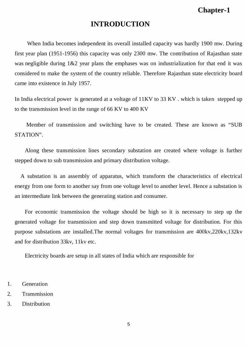
When India becomes independent its overall installed capacity was hardly 1900 mw. During
first year plan (1951-1956) this capacity was only 2300 mw. The contribution of Rajasthan state
was negligible during 1&2 year plans the emphases was on industrialization for that end it was
considered to make the system of the country reliable. Therefore Rajasthan state electricity board
came into existence in July 1957.
In India electrical power is generated at a voltage of 11KV to 33 KV . which is taken stepped up
to the transmission level in the range of 66 KV to 400 KV
Member of transmission and switching have to be created. These are known as “SUB
STATION”.
Along these transmission lines secondary substation are created where voltage is further
stepped down to sub transmission and primary distribution voltage.
A substation is an assembly of apparatus, which transform the characteristics of electrical
energy from one form to another say from one voltage level to another level. Hence a substation is
an intermediate link between the generating station and consumer.
For economic transmission the voltage should be high so it is necessary to step up the
generated voltage for transmission and step down transmitted voltage for distribution. For this
purpose substations are installed.The normal voltages for transmission are 400kv,220kv,132kv
and for distribution 33kv, 11kv etc.
Electricity boards are setup in all states of India which are responsible for
1. Generation
2. Transmission
3. Distribution
6
They also construct, install and maintain all the station made for these purpose. In Rajasthan
,R.R.V.P.N.L. is responsible for transmission and distribution of electrical power all over
Rajasthan. It has its own generating station and it’s also gets power from various other stations
also. It gets power from following stations:-
1. Badarpur Thermal Power Station Delhi
2. BhakaraNangl Project (at satlaj in Punjab)
3. Gandhi Sagar Dam Kota
4. Jawahar Dam Kota
5. RanaPratapSagar Dam Kota
6. Rajasthan Atomic Power Plant (RAPP) Kota
7. Kota Super Thermal Power Station (KSTPS) Kota
8. Anta Gas Power Plant Anta
9. Rajasthan share in Bhakara Beas Management Board (BBMB)
Power obtain from these stations is transmitted all over Rajasthan with the help of grid stations.
Depending on the purpose, substations may be classified as:-
1. Step up substation
2. Primary grid substation
3. Secondary substation
4. Distribution substation
5. Bulky supply and industrial substation
6. Mining substation
7. Mobile substation
8. Cinematograph substation
Depending on constructional feature substation are classified as:-
1. Outdoor type
2. Indoor type
3. Basement or Underground type
4. Pole mounting open or kilos type
7
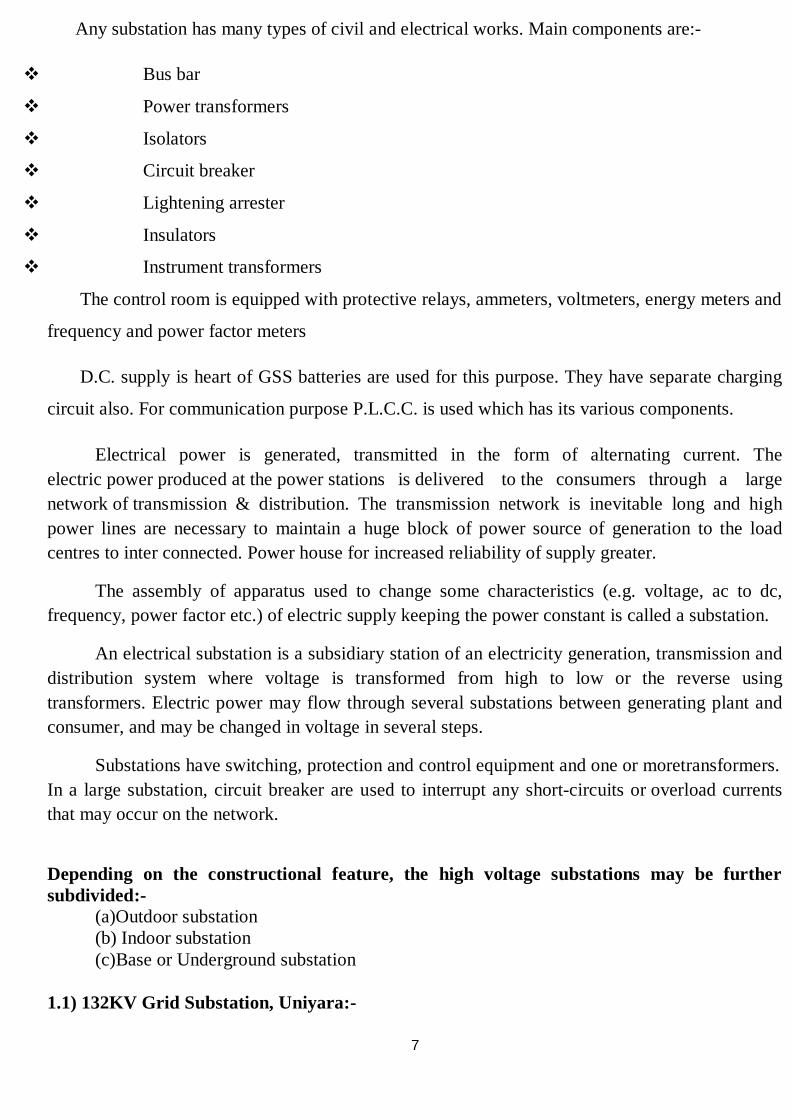
Any substation has many types of civil and electrical works. Main components are:-
Bus bar
Power transformers
Isolators
Circuit breaker
Lightening arrester
Insulators
Instrument transformers
The control room is equipped with protective relays, ammeters, voltmeters, energy meters and
frequency and power factor meters
D.C. supply is heart of GSS batteries are used for this purpose. They have separate charging
circuit also. For communication purpose P.L.C.C. is used which has its various components.
Electrical power is generated, transmitted in the form of alternating current. The electric power produced at the power stations is delivered to the consumers through a large network of transmission & distribution. The transmission network is inevitable long and high power lines are necessary to maintain a huge block of power source of generation to the load centres to inter connected. Power house for increased reliability of supply greater.
The assembly of apparatus used to change some characteristics (e.g. voltage, ac to dc, frequency, power factor etc.) of electric supply keeping the power constant is called a substation.
An electrical substation is a subsidiary station of an electricity generation, transmission and distribution system where voltage is transformed from high to low or the reverse using transformers. Electric power may flow through several substations between generating plant and consumer, and may be changed in voltage in several steps.
Substations have switching, protection and control equipment and one or moretransformers. In a large substation, circuit breaker are used to interrupt any short-circuits or overload currents that may occur on the network.
Depending on the constructional feature, the high voltage substations may be further subdivided:-
(a)Outdoor substation (b) Indoor substation (c)Base or Underground substation
1.1) 132KV Grid Substation, Uniyara:-
8
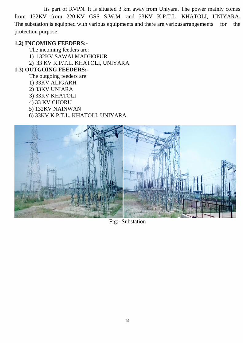
Its part of RVPN. It is situated 3 km away from Uniyara. The power mainly comes from 132KV from 220 KV GSS S.W.M. and 33KV K.P.T.L. KHATOLI, UNIYARA. The substation is equipped with various equipments and there are variousarrangements for the protection purpose.
1.2) INCOMING FEEDERS:- The incoming feeders are: 1) 132KV SAWAI MADHOPUR 2) 33 KV K.P.T.L. KHATOLI, UNIYARA.
1.3) OUTGOING FEEDERS:- The outgoing feeders are:
1) 33KV ALIGARH 2) 33KV UNIARA 3) 33KV KHATOLI 4) 33 KV CHORU 5) 132KV NAINWAN 6) 33KV K.P.T.L. KHATOLI, UNIYARA.
Fig:- Substation
9
Chapter-2
Single Line Diagram
2.1) Definition of single line diagram:-
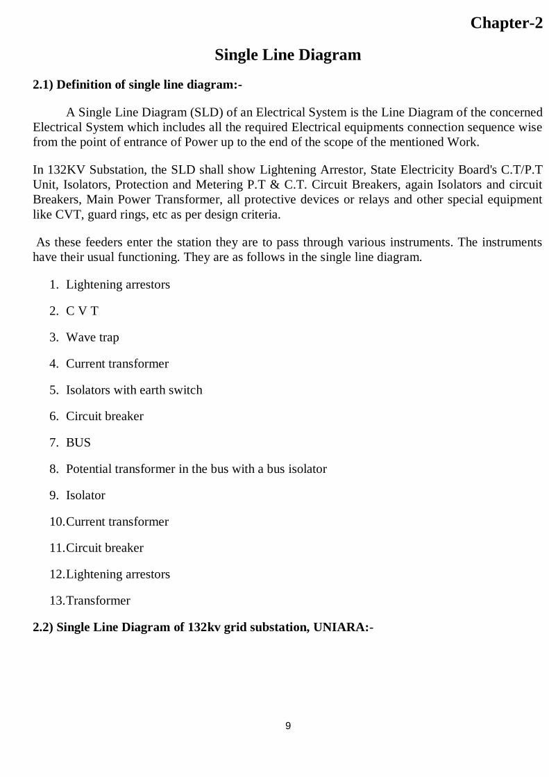
A Single Line Diagram (SLD) of an Electrical System is the Line Diagram of the concerned Electrical System which includes all the required Electrical equipments connection sequence wise from the point of entrance of Power up to the end of the scope of the mentioned Work.
In 132KV Substation, the SLD shall show Lightening Arrestor, State Electricity Board's C.T/P.T Unit, Isolators, Protection and Metering P.T & C.T. Circuit Breakers, again Isolators and circuit Breakers, Main Power Transformer, all protective devices or relays and other special equipment like CVT, guard rings, etc as per design criteria.
As these feeders enter the station they are to pass through various instruments. The instruments have their usual functioning. They are as follows in the single line diagram.
1. Lightening arrestors
2. C V T
3. Wave trap
4. Current transformer
5. Isolators with earth switch
6. Circuit breaker
7. BUS
8. Potential transformer in the bus with a bus isolator
9. Isolator
10. Current transformer
11. Circuit breaker
12. Lightening arrestors
13. Transformer
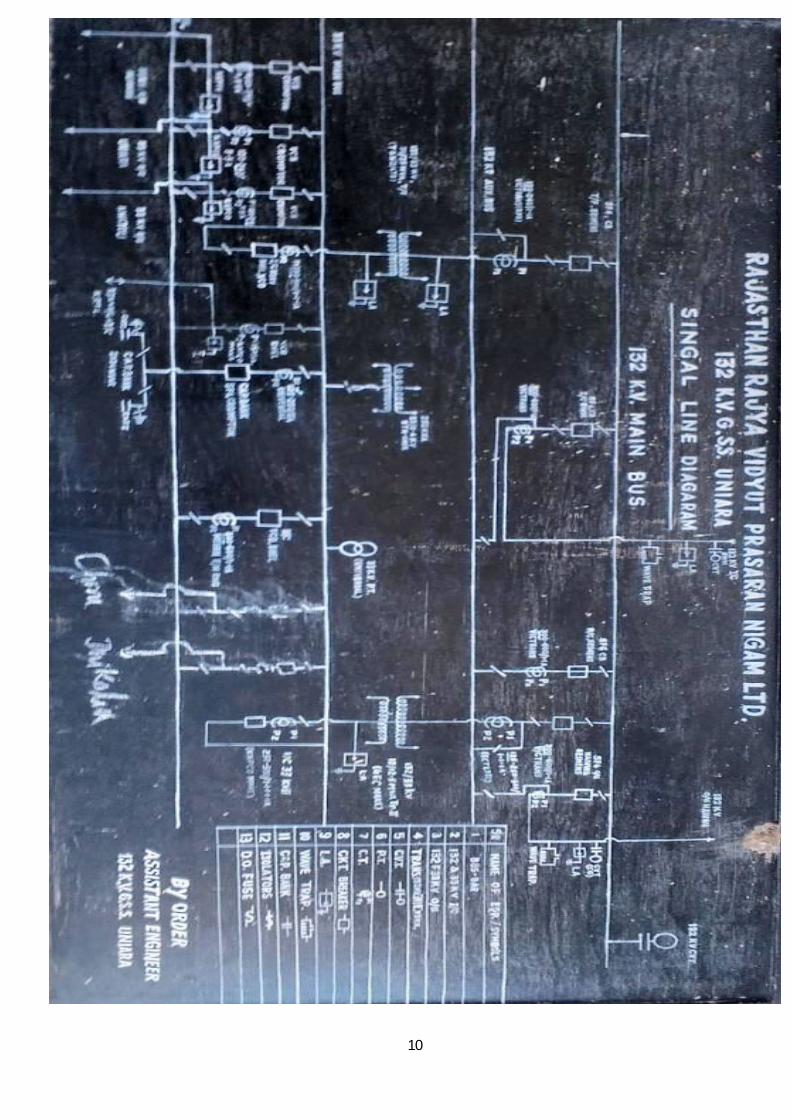
2.2) Single Line Diagram of 132kv grid substation, UNIARA:-
10
11
Chapter-3
Lighting Arrester
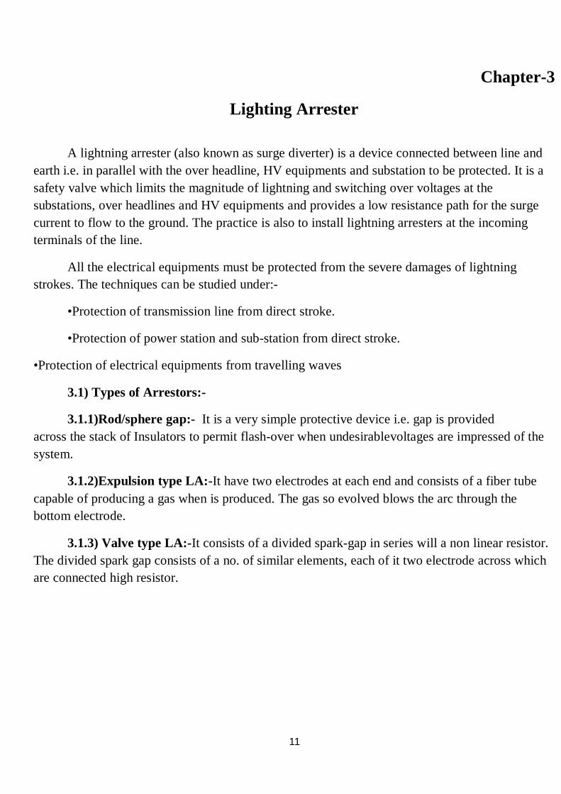
A lightning arrester (also known as surge diverter) is a device connected between line and earth i.e. in parallel with the over headline, HV equipments and substation to be protected. It is a safety valve which limits the magnitude of lightning and switching over voltages at the substations, over headlines and HV equipments and provides a low resistance path for the surge current to flow to the ground. The practice is also to install lightning arresters at the incoming terminals of the line.
All the electrical equipments must be protected from the severe damages of lightning strokes. The techniques can be studied under:-
•Protection of transmission line from direct stroke.
•Protection of power station and sub-station from direct stroke.
•Protection of electrical equipments from travelling waves
3.1) Types of Arrestors:-
3.1.1)Rod/sphere gap:- It is a very simple protective device i.e. gap is provided across the stack of Insulators to permit flash-over when undesirablevoltages are impressed of the system.
3.1.2)Expulsion type LA:-It have two electrodes at each end and consists of a fiber tube capable of producing a gas when is produced. The gas so evolved blows the arc through the bottom electrode.
3.1.3) Valve type LA:-It consists of a divided spark-gap in series will a non linear resistor. The divided spark gap consists of a no. of similar elements, each of it two electrode across which are connected high resistor.
12
Fig:- Lighting Arrester
13
Chapter-4
Busbar
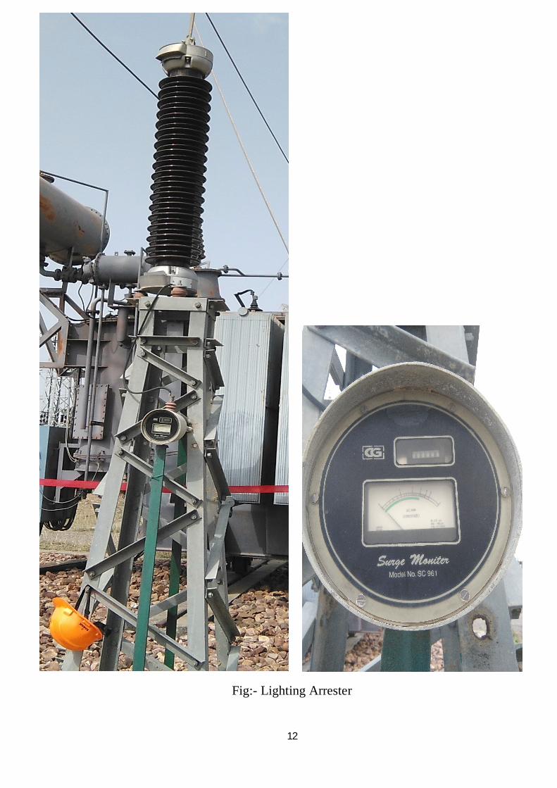
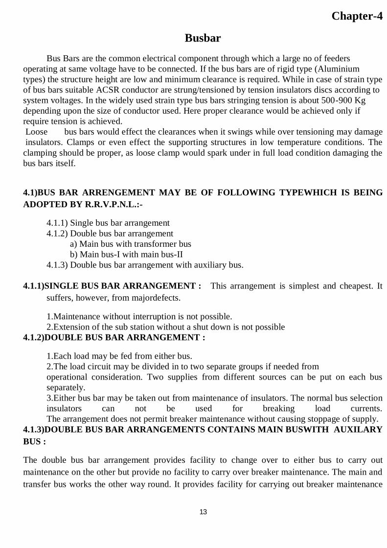
Bus Bars are the common electrical component through which a large no of feeders operating at same voltage have to be connected. If the bus bars are of rigid type (Aluminium types) the structure height are low and minimum clearance is required. While in case of strain type of bus bars suitable ACSR conductor are strung/tensioned by tension insulators discs according to system voltages. In the widely used strain type bus bars stringing tension is about 500-900 Kg depending upon the size of conductor used. Here proper clearance would be achieved only if require tension is achieved. Loose bus bars would effect the clearances when it swings while over tensioning may damage insulators. Clamps or even effect the supporting structures in low temperature conditions. The clamping should be proper, as loose clamp would spark under in full load condition damaging the bus bars itself.
4.1)BUS BAR ARRENGEMENT MAY BE OF FOLLOWING TYPEWHICH IS BEING ADOPTED BY R.R.V.P.N.L.:-
4.1.1) Single bus bar arrangement 4.1.2) Double bus bar arrangement
a) Main bus with transformer bus b) Main bus-I with main bus-II
4.1.3) Double bus bar arrangement with auxiliary bus.
4.1.1)SINGLE BUS BAR ARRANGEMENT : This arrangement is simplest and cheapest. It suffers, however, from majordefects.
1.Maintenance without interruption is not possible. 2.Extension of the sub station without a shut down is not possible
4.1.2)DOUBLE BUS BAR ARRANGEMENT :
1.Each load may be fed from either bus. 2.The load circuit may be divided in to two separate groups if needed from operational consideration. Two supplies from different sources can be put on each bus separately. 3.Either bus bar may be taken out from maintenance of insulators. The normal bus selection insulators can not be used for breaking load currents. The arrangement does not permit breaker maintenance without causing stoppage of supply.
4.1.3)DOUBLE BUS BAR ARRANGEMENTS CONTAINS MAIN BUSWITH AUXILARY BUS :
The double bus bar arrangement provides facility to change over to either bus to carry out maintenance on the other but provide no facility to carry over breaker maintenance. The main and transfer bus works the other way round. It provides facility for carrying out breaker maintenance
14
but does not permit bus maintenance. Whenever maintenance is required on any breaker the circuit is changed over to the transfer bus and is controlled through bus coupler breaker
Fig. - Bus Bar
.
15
Chapter-5
Insulator
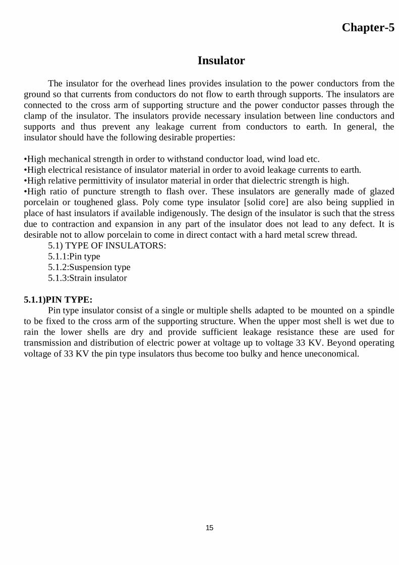
The insulator for the overhead lines provides insulation to the power conductors from the ground so that currents from conductors do not flow to earth through supports. The insulators are connected to the cross arm of supporting structure and the power conductor passes through the clamp of the insulator. The insulators provide necessary insulation between line conductors and supports and thus prevent any leakage current from conductors to earth. In general, the insulator should have the following desirable properties: •High mechanical strength in order to withstand conductor load, wind load etc. •High electrical resistance of insulator material in order to avoid leakage currents to earth. •High relative permittivity of insulator material in order that dielectric strength is high. •High ratio of puncture strength to flash over. These insulators are generally made of glazed porcelain or toughened glass. Poly come type insulator [solid core] are also being supplied in place of hast insulators if available indigenously. The design of the insulator is such that the stress due to contraction and expansion in any part of the insulator does not lead to any defect. It is desirable not to allow porcelain to come in direct contact with a hard metal screw thread.
5.1) TYPE OF INSULATORS: 5.1.1:Pin type 5.1.2:Suspension type 5.1.3:Strain insulator
5.1.1)PIN TYPE: Pin type insulator consist of a single or multiple shells adapted to be mounted on a spindle to be fixed to the cross arm of the supporting structure. When the upper most shell is wet due to rain the lower shells are dry and provide sufficient leakage resistance these are used for transmission and distribution of electric power at voltage up to voltage 33 KV. Beyond operating voltage of 33 KV the pin type insulators thus become too bulky and hence uneconomical.
16
Fig:- Insulators
5.1.2)SUSPENSION TYPE: Suspension type insulators consist of a number of porcelain disc connected in series by metal links in the form of a string. Its working voltage is 66KV. Each disc is designed for low voltage for 11KV. 5.1.3)STRAIN INSULATOR:
The strain insulators are exactly identical in shape with the suspension insulators. These strings are placed in the horizontal plane rather than the vertical plane. These insulators are used where line issubjected to greater tension. For low voltage lines (< 11KV) shackle insulator a reused as strain insulator.
17
Chapter-6 ISOLATORS
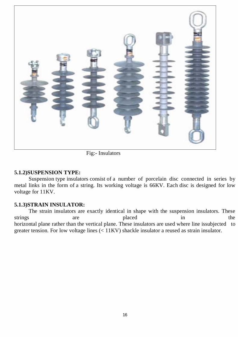
“Isolator" is one, which can break and make an electric circuit in no load condition. These are normally used in various circuits for the purposes of Isolation of a certain portion when required for maintenance etc. Isolation of a certain portion when required for maintenance etc."Switching Isolators" are capable of
•Interrupting transformer magnetized currents •Interrupting line charging current •Load transfer switching Its main application is in connection with transformer feeder as this unit makes it possible to
switch out one transformer, while the other is still on load. The most common type of isolators is the rotating centre pots type in which each phase has three insulator post, with the outer posts carrying fixed contacts and connections while the centre post having contact arm which is arranged to move through 90` on its axis. The following interlocks are provided with isolator:
a) Bus 1 and2 isolators cannot be closed simultaneously. b) Isolator cannot operate unless the breaker is open. c) Only one bay can be taken on bypass bus. d) No isolator can operate when corresponding earth switch is on breaker.
Fig:- Isolator
18
Chapter-7 CIRCUIT BREAKER
The function of relays and circuit breakers in the operation of a power system is to prevent
or limit damage during faults or overloads, and to minimize their effect on the remainder of the system. This is accomplished by dividing the system into protective zones separated by circuit breakers. During a fault, the zone which includes the faulted apparatus is de-energized and disconnected from the system. In addition to its protective function, a circuit breaker is also used for circuit switching under normal conditions. Each having its protective relays for determining the existence of a fault in that zone and having circuit breakers for disconnecting that zone from the system. It is desirable to restrict the amount of system disconnected by a given fault; as for example to a single transformer, line section, machine, or bus section. However, economic considerations frequently limit the number of circuit breakers to those required for normal operation and some compromises result in the relay protection.Some of the manufacturers are ABB, AREVA, Cutler-Hammer (Eaton), MitsubishiElectric, Pennsylvania Breaker, Schneider Electric, Siemens, Toshiba, Koncar HVS and others. Circuit breaker can be classified as "live tank", where the enclosure that contains the breaking mechanism is at line potential, or dead tank with the enclosure at earth potential. High-voltage AC circuit breakers are routinely available with ratings up to 765,000 volts. 7.1) Various types of circuit breakers:-
7.1.1) SF6 Circuit Breaker 7.1.2) Air Blast Circuit Breaker 7.1.3) Oil Circuit Breaker 7.1.4) Bulk Oil Circuit Breaker (MOCB) 7.1.5) Minimum Oil Circuit Breaker
7.1.1) SF6 CIRCUIT BREAKER:- Sulphur hexafluoride has proved its-self as an excellent insulating and arc quenching
medium. It has been extensively used during the last 30 years in circuit breakers, gas-insulated switchgear (GIS), high voltage capacitors, bushings, and gas insulated transmission lines. In SF6 breakers the contacts are surrounded by low pressure SF6 gas. At the moment the contacts are opened, a small amount of gas is compressed and forced through the arc to extinguish it. 7.1.2) AIR BLAST CIRCUIT BREAKER:
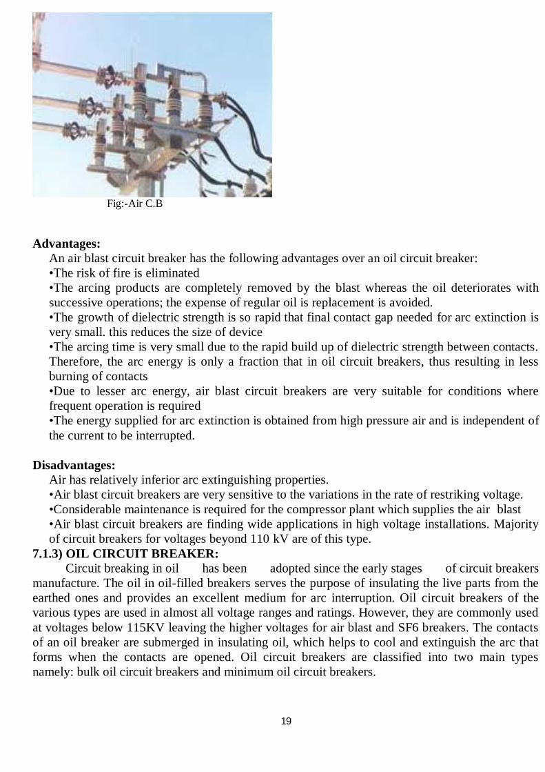
The principle of arc interruption in air blast circuit breakers is to direct a blast of air, at high pressure and velocity, to the arc. Fresh and dry air of the air blast will replace the ionized hot gases within the arc zone and the arc length is considerably increased. Consequently the arc may be interrupted at the first natural current zero. In this type of breaker, the contacts are surrounded by compressed air. When the contacts are opened the compressed air is released in forced blast through the arc to the atmosphere extinguishing the arc in the process.
19
Fig:-Air C.B
Advantages:
An air blast circuit breaker has the following advantages over an oil circuit breaker: •The risk of fire is eliminated •The arcing products are completely removed by the blast whereas the oil deteriorates with successive operations; the expense of regular oil is replacement is avoided. •The growth of dielectric strength is so rapid that final contact gap needed for arc extinction is very small. this reduces the size of device •The arcing time is very small due to the rapid build up of dielectric strength between contacts. Therefore, the arc energy is only a fraction that in oil circuit breakers, thus resulting in less burning of contacts •Due to lesser arc energy, air blast circuit breakers are very suitable for conditions where frequent operation is required •The energy supplied for arc extinction is obtained from high pressure air and is independent of the current to be interrupted.
Disadvantages:
Air has relatively inferior arc extinguishing properties. •Air blast circuit breakers are very sensitive to the variations in the rate of restriking voltage. •Considerable maintenance is required for the compressor plant which supplies the air blast •Air blast circuit breakers are finding wide applications in high voltage installations. Majority of circuit breakers for voltages beyond 110 kV are of this type.
7.1.3) OIL CIRCUIT BREAKER: Circuit breaking in oil has been adopted since the early stages of circuit breakers
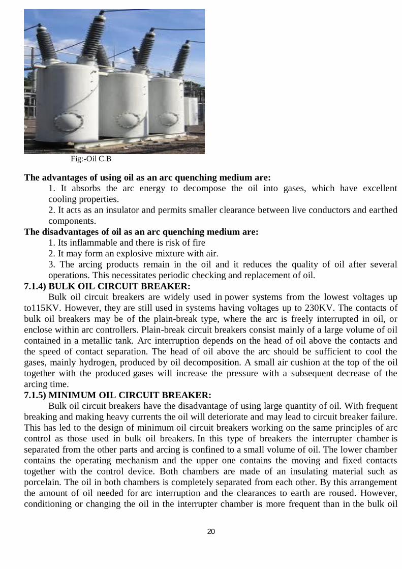
manufacture. The oil in oil-filled breakers serves the purpose of insulating the live parts from the earthed ones and provides an excellent medium for arc interruption. Oil circuit breakers of the various types are used in almost all voltage ranges and ratings. However, they are commonly used at voltages below 115KV leaving the higher voltages for air blast and SF6 breakers. The contacts of an oil breaker are submerged in insulating oil, which helps to cool and extinguish the arc that forms when the contacts are opened. Oil circuit breakers are classified into two main types namely: bulk oil circuit breakers and minimum oil circuit breakers.
20
Fig:-Oil C.B
The advantages of using oil as an arc quenching medium are: 1. It absorbs the arc energy to decompose the oil into gases, which have excellent cooling properties. 2. It acts as an insulator and permits smaller clearance between live conductors and earthed components.
The disadvantages of oil as an arc quenching medium are: 1. Its inflammable and there is risk of fire 2. It may form an explosive mixture with air. 3. The arcing products remain in the oil and it reduces the quality of oil after several operations. This necessitates periodic checking and replacement of oil.
7.1.4) BULK OIL CIRCUIT BREAKER: Bulk oil circuit breakers are widely used in power systems from the lowest voltages up
to115KV. However, they are still used in systems having voltages up to 230KV. The contacts of bulk oil breakers may be of the plain-break type, where the arc is freely interrupted in oil, or enclose within arc controllers. Plain-break circuit breakers consist mainly of a large volume of oil contained in a metallic tank. Arc interruption depends on the head of oil above the contacts and the speed of contact separation. The head of oil above the arc should be sufficient to cool the gases, mainly hydrogen, produced by oil decomposition. A small air cushion at the top of the oil together with the produced gases will increase the pressure with a subsequent decrease of the arcing time. 7.1.5) MINIMUM OIL CIRCUIT BREAKER:
Bulk oil circuit breakers have the disadvantage of using large quantity of oil. With frequent breaking and making heavy currents the oil will deteriorate and may lead to circuit breaker failure. This has led to the design of minimum oil circuit breakers working on the same principles of arc control as those used in bulk oil breakers. In this type of breakers the interrupter chamber is separated from the other parts and arcing is confined to a small volume of oil. The lower chamber contains the operating mechanism and the upper one contains the moving and fixed contacts together with the control device. Both chambers are made of an insulating material such as porcelain. The oil in both chambers is completely separated from each other. By this arrangement the amount of oil needed for arc interruption and the clearances to earth are roused. However, conditioning or changing the oil in the interrupter chamber is more frequent than in the bulk oil

21
breakers. This is due to carbonization and slugging from arcs interrupted chamber is equipped with a discharge vent and silica gel breather to permit a small gas cushion on top of the oil. Single break minimum oil breakers are available in the voltage range 13.8 to 34.5 KV.
22
Chapter-8
PROTECTIVE RELAY
Relays must be able to evaluate a wide variety of parameters to establish that corrective action is required. Obviously, a relay cannot prevent the fault. Its primary purpose is to detect the fault and take the necessary action to minimize the damage to the equipment or to the system. The most common parameters which reflect the presence of a fault are the voltages and currents at the terminals of the protected apparatus or at the appropriate zone boundaries. The fundamental problem in power system protection is to define the quantities that can differentiate between normal and abnormal conditions. This problem is compounded by the fact that “normal” in the present sense means outside the zone of protection. This aspect, which is of the greatestsignificance in designing a secure relaying system, dominates the design of all protection systems. 8.1)Distance Relays:
Distance relays respond to the voltage and current, i.e., the impedance, at the relay location. The impedance per mile is fairly constant so these relays respond to the distance between the relay location and the fault location. As the power systems become more complex and the fault current varies with changes in generation and system configuration, directional over current relays become difficult to apply and to set for all contingencies, whereas the distance relay setting is constant for a wide variety of changes external to the protected line. 8.2)Types of Distance relay:- 8.2.1) Impedance Relay:
The impedance relay has a circular characteristic centred. It is non directional and is used primarily as a fault detector. 8.2.2) Admittance Relay:
The admittance relay is the most commonly used distance relay. It is the tripping relay in pilot schemes and as the backup relay in step distance schemes. In the electromechanical design it is circular, and in the solid state design, it can be shaped to correspond to the transmission line impedance. 8.2.3) Reactance Relay:
The reactance relay is a straight-line characteristic that responds only to the reactance of the protected line. It is non directional and is used to supplement the admittance relay as a tripping relay to make the overall protection independent of resistance. It is particularly useful on short lines where the fault arc resistance is the same order of magnitude as the line length.
23
Chapter-9
POWER TRANSFORMER
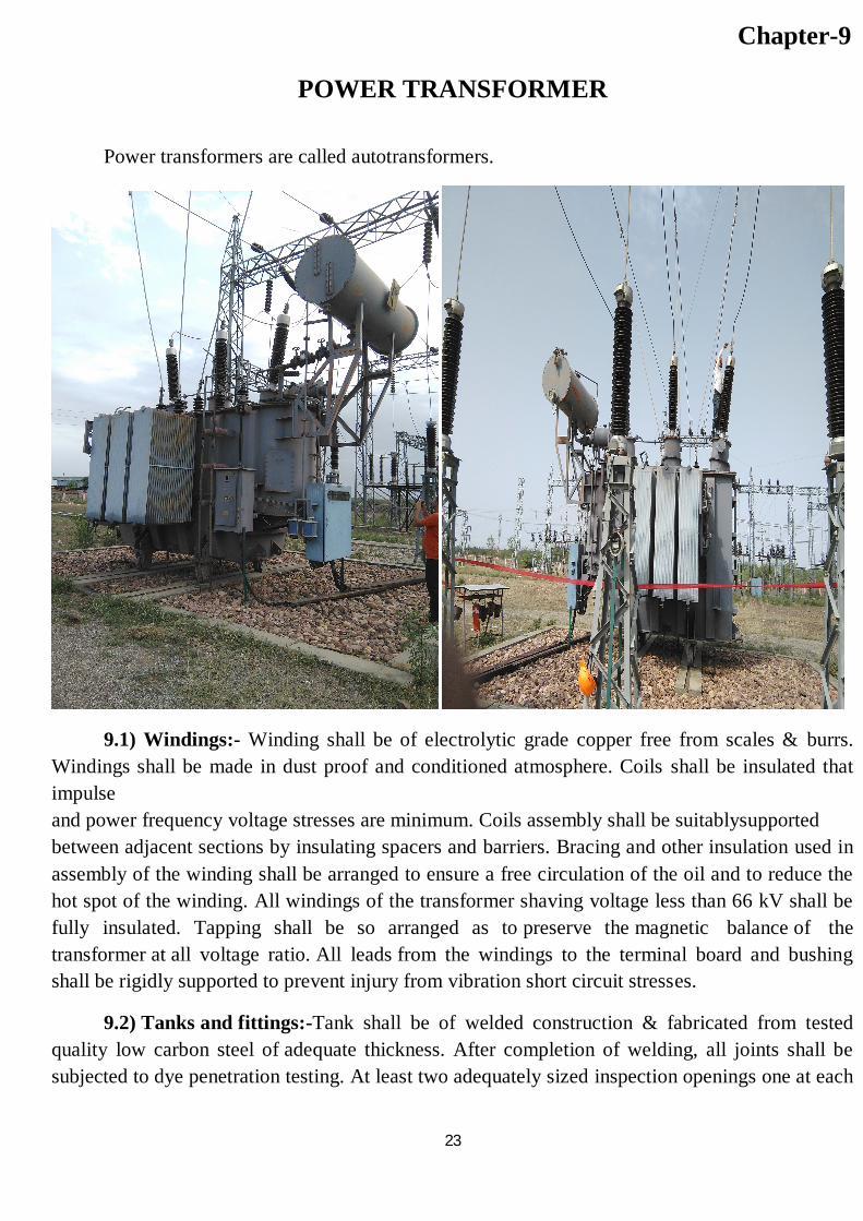
Power transformers are called autotransformers.
9.1) Windings:- Winding shall be of electrolytic grade copper free from scales & burrs. Windings shall be made in dust proof and conditioned atmosphere. Coils shall be insulated that impulse and power frequency voltage stresses are minimum. Coils assembly shall be suitablysupported between adjacent sections by insulating spacers and barriers. Bracing and other insulation used in assembly of the winding shall be arranged to ensure a free circulation of the oil and to reduce the hot spot of the winding. All windings of the transformer shaving voltage less than 66 kV shall be fully insulated. Tapping shall be so arranged as to preserve the magnetic balance of the transformer at all voltage ratio. All leads from the windings to the terminal board and bushing shall be rigidly supported to prevent injury from vibration short circuit stresses.
9.2) Tanks and fittings:-Tank shall be of welded construction & fabricated from tested quality low carbon steel of adequate thickness. After completion of welding, all joints shall be subjected to dye penetration testing. At least two adequately sized inspection openings one at each
24
end of the tank shall be provided for easy access to bushing & earth connections. Turrets & other parts surrounding the conductor of individual phase shall be non-magnetic. The main tank body including tap changing compartment, radiators shall be capable of withstanding full vacuum.
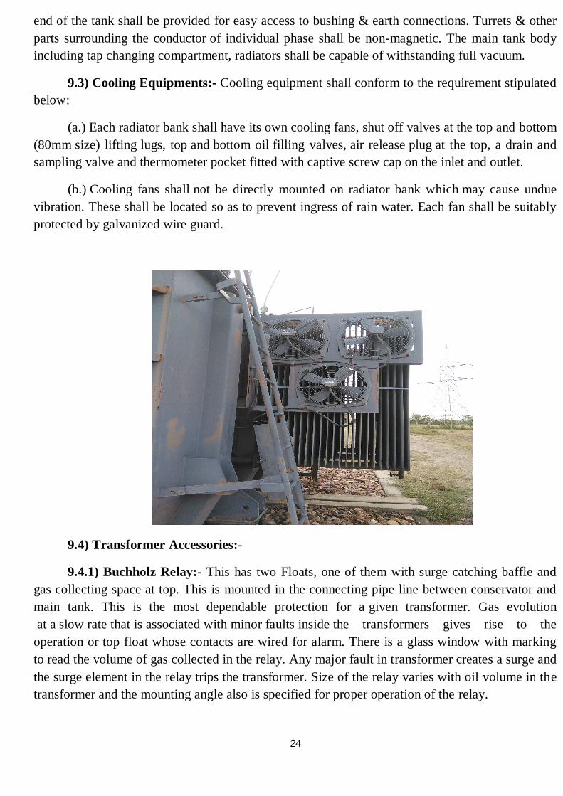
9.3) Cooling Equipments:- Cooling equipment shall conform to the requirement stipulated below:
(a.) Each radiator bank shall have its own cooling fans, shut off valves at the top and bottom (80mm size) lifting lugs, top and bottom oil filling valves, air release plug at the top, a drain and sampling valve and thermometer pocket fitted with captive screw cap on the inlet and outlet.
(b.) Cooling fans shall not be directly mounted on radiator bank which may cause undue vibration. These shall be located so as to prevent ingress of rain water. Each fan shall be suitably protected by galvanized wire guard.
9.4) Transformer Accessories:-
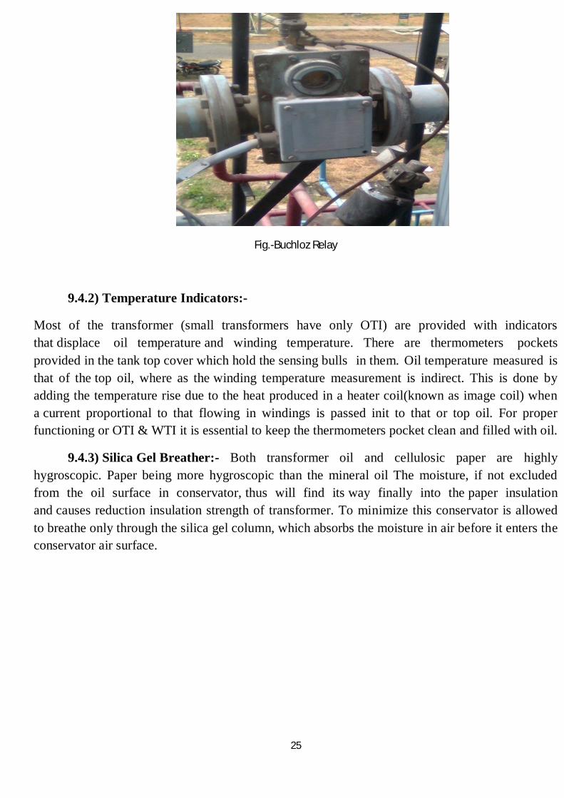
9.4.1) Buchholz Relay:- This has two Floats, one of them with surge catching baffle and gas collecting space at top. This is mounted in the connecting pipe line between conservator and main tank. This is the most dependable protection for a given transformer. Gas evolution at a slow rate that is associated with minor faults inside the transformers gives rise to the operation or top float whose contacts are wired for alarm. There is a glass window with marking to read the volume of gas collected in the relay. Any major fault in transformer creates a surge and the surge element in the relay trips the transformer. Size of the relay varies with oil volume in the transformer and the mounting angle also is specified for proper operation of the relay.
25
Fig.-Buchloz Relay
9.4.2) Temperature Indicators:-
Most of the transformer (small transformers have only OTI) are provided with indicators that displace oil temperature and winding temperature. There are thermometers pockets provided in the tank top cover which hold the sensing bulls in them. Oil temperature measured is that of the top oil, where as the winding temperature measurement is indirect. This is done by adding the temperature rise due to the heat produced in a heater coil(known as image coil) when a current proportional to that flowing in windings is passed init to that or top oil. For proper functioning or OTI & WTI it is essential to keep the thermometers pocket clean and filled with oil.
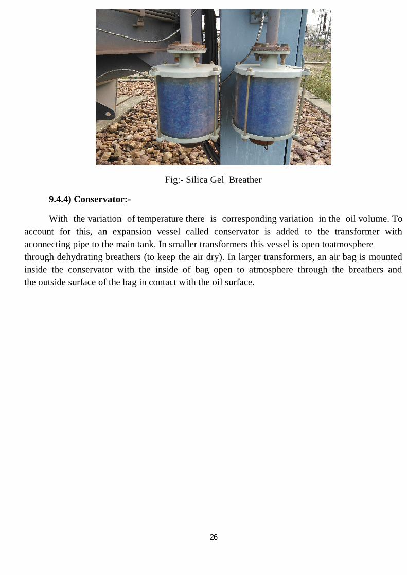
9.4.3) Silica Gel Breather:- Both transformer oil and cellulosic paper are highly hygroscopic. Paper being more hygroscopic than the mineral oil The moisture, if not excluded from the oil surface in conservator, thus will find its way finally into the paper insulation and causes reduction insulation strength of transformer. To minimize this conservator is allowed to breathe only through the silica gel column, which absorbs the moisture in air before it enters the conservator air surface.
26
Fig:- Silica Gel Breather
9.4.4) Conservator:-
With the variation of temperature there is corresponding variation in the oil volume. To account for this, an expansion vessel called conservator is added to the transformer with aconnecting pipe to the main tank. In smaller transformers this vessel is open toatmosphere through dehydrating breathers (to keep the air dry). In larger transformers, an air bag is mounted inside the conservator with the inside of bag open to atmosphere through the breathers and the outside surface of the bag in contact with the oil surface.
27
Chapter-10
CURRENT TRANSFORMER
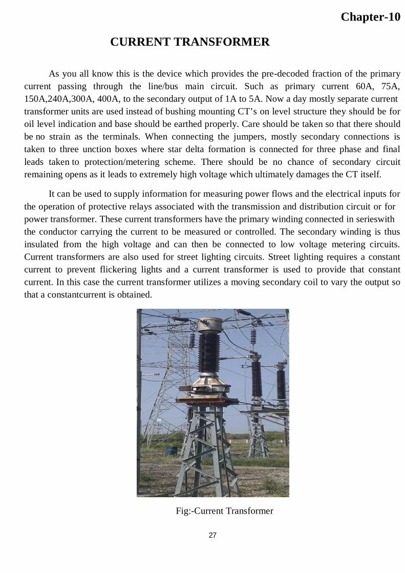
As you all know this is the device which provides the pre-decoded fraction of the primary current passing through the line/bus main circuit. Such as primary current 60A, 75A, 150A,240A,300A, 400A, to the secondary output of 1A to 5A. Now a day mostly separate current transformer units are used instead of bushing mounting CT’s on level structure they should be for oil level indication and base should be earthed properly. Care should be taken so that there should be no strain as the terminals. When connecting the jumpers, mostly secondary connections is taken to three unction boxes where star delta formation is connected for three phase and final leads taken to protection/metering scheme. There should be no chance of secondary circuit remaining opens as it leads to extremely high voltage which ultimately damages the CT itself.
It can be used to supply information for measuring power flows and the electrical inputs for the operation of protective relays associated with the transmission and distribution circuit or for power transformer. These current transformers have the primary winding connected in serieswith the conductor carrying the current to be measured or controlled. The secondary winding is thus insulated from the high voltage and can then be connected to low voltage metering circuits. Current transformers are also used for street lighting circuits. Street lighting requires a constant current to prevent flickering lights and a current transformer is used to provide that constant current. In this case the current transformer utilizes a moving secondary coil to vary the output so that a constantcurrent is obtained.
Fig:-Current Transformer
28
Chapter-11
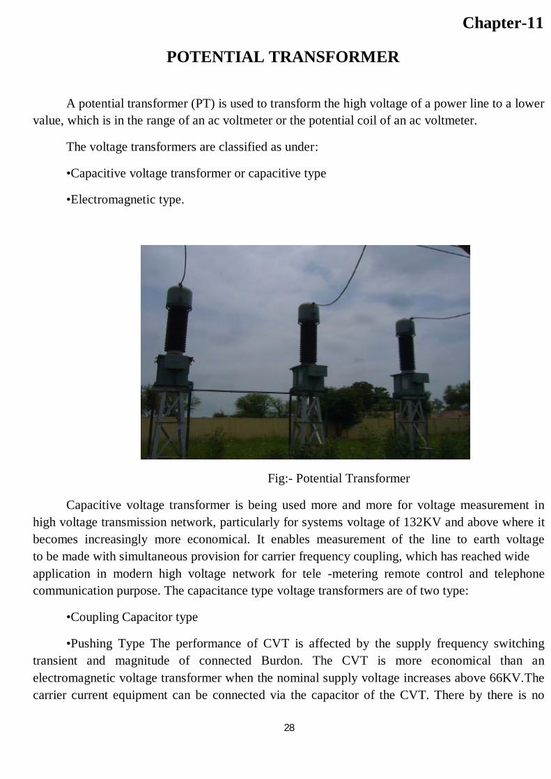
POTENTIAL TRANSFORMER A potential transformer (PT) is used to transform the high voltage of a power line to a lower
value, which is in the range of an ac voltmeter or the potential coil of an ac voltmeter.
The voltage transformers are classified as under:
•Capacitive voltage transformer or capacitive type
•Electromagnetic type.
Fig:- Potential Transformer
Capacitive voltage transformer is being used more and more for voltage measurement in high voltage transmission network, particularly for systems voltage of 132KV and above where it becomes increasingly more economical. It enables measurement of the line to earth voltage to be made with simultaneous provision for carrier frequency coupling, which has reached wide application in modern high voltage network for tele -metering remote control and telephone communication purpose. The capacitance type voltage transformers are of two type:
•Coupling Capacitor type
•Pushing Type The performance of CVT is affected by the supply frequency switching transient and magnitude of connected Burdon. The CVT is more economical than an electromagnetic voltage transformer when the nominal supply voltage increases above 66KV.The carrier current equipment can be connected via the capacitor of the CVT. There by there is no
29
need of separate coupling capacitor. The capacitor connected in series act like potential dividers, provided, the current taken by burden is negligible compared with current passing through the series connected capacitor.
CVT as coupling capacitor for carrier current application:-The carrier current equipments is connected to the power line via coupling capacitor. The coupling CVT combines the function of coupling and voltage transformer.
30
Chapter-12
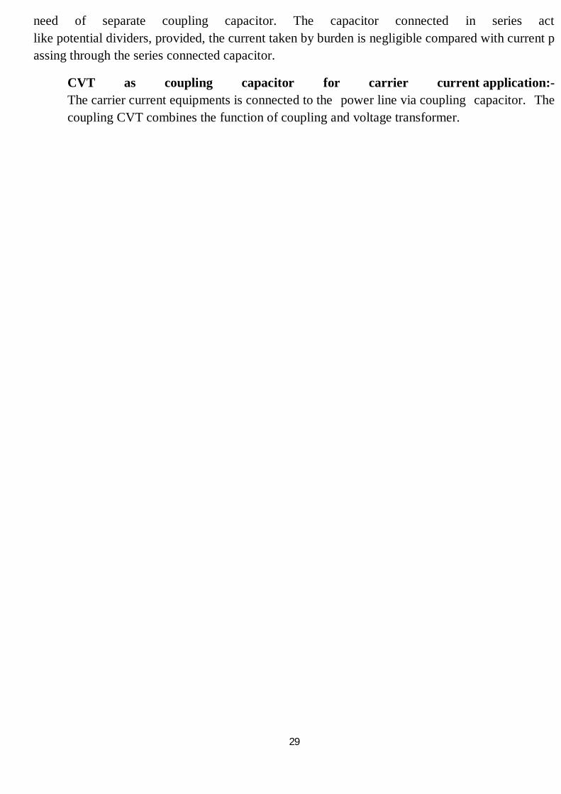
CAPACITIVE VOLTAGE TRANSFORMER A capacitor voltage transformer (CVT) is a transformer used in power systems to step-down
extra high voltage signals and provide low voltage signals either for measurement or to operate a protective relay. In its most basic form the device consists of three parts: two capacitors across which the voltage signal is split, an inductive element used to tune the device to the supply frequency and a transformer used to isolate and further step-down the voltage for the instrumentation or protective relay. The device has at least four terminals, a high-voltageterminal for connection to the high voltage signal, a ground terminal and at least one set of secondary terminals for connection to the instrumentation or protective relay. CVTs are typically single-phase devices used for measuring voltages in excess of one hundred kilovolts where the use of voltage transformers would be uneconomical. In practice the first capacitor, C1, is often replaced by a stack of capacitors connected in series. This results in a large voltage drop across the stack of capacitors that replaced the first capacitor and a comparatively small voltage drop across the second capacitor, C2, and hence the secondary terminals. The porcelain in multi unit stack, all the potentials points are electrically tied and suitably shielded to overcome the effect of corona RIV etc. Capacitive voltage transformers are available for system voltage.
Fig.- Capacitive Voltage Transformer
31
Chapter-13
CONTROL ROOM
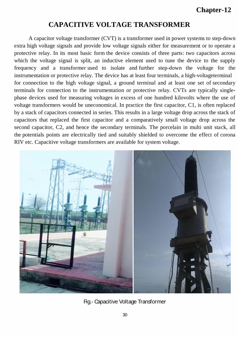
Control panel contain meters, control switches and recorders located in the control building, also called the dog house. These are used to control the substation equipment to send power from one circuit to another or to open or to shut down circuits when needed.
13.1) MEASURING INSTRUMENT USED:
13.1.1)ENERGY METER: To measure the energy transmitted energy meters are fitted tothe panel to different feeders the energy transmitted is recorded after one hour regularly for it MWHr, meter is provided.
13.1.2)WATT METERS: It is attached to each feeder to record the power exported from GSS.
13.1.3)FREQUENCY METER: To measure the frequency at each feeder there is the provision of analog or digital frequency meter.
13.1.4)VOLT METER: It is provided to measure the phase to phase voltage .It is also available in both the analog and digital frequency meter.
13.1.5)AMETER: It is provided to measure the line current. It is also available in both the forms analog as well as digital.
13.1.6)MAXIMUM DEMAND INDICATOR: There are also mounted the control panel to record the average power over successive predetermined period.
13.1.7) MVAR METER: It is to measure the reactive power of the circuit.
Fig:- Control Room
32
Chapter-14
CAPACITOR BANK
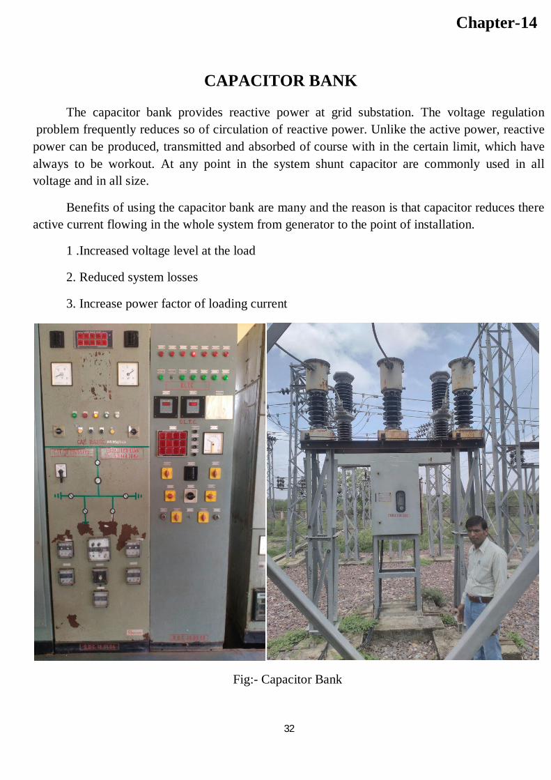
The capacitor bank provides reactive power at grid substation. The voltage regulation problem frequently reduces so of circulation of reactive power. Unlike the active power, reactive power can be produced, transmitted and absorbed of course with in the certain limit, which have always to be workout. At any point in the system shunt capacitor are commonly used in all voltage and in all size.
Benefits of using the capacitor bank are many and the reason is that capacitor reduces there active current flowing in the whole system from generator to the point of installation.
1 .Increased voltage level at the load
2. Reduced system losses
3. Increase power factor of loading current
Fig:- Capacitor Bank
33
Chapter-15
POWER LINE CARRIER COMMUNICATION
As electronics plays a vital role in the industrial growth, communication is also a backbone of any power stations. Communication between various generating and receiving station is very essential for proper operation of power of power system. This is more in case of large interconnected system where a control leads dispatch station has to co-ordinate the working of various unit to see that the system is maintained in the optimum working condition, power line communication is most economic and reliable method of communication for medium and long distance in power network.
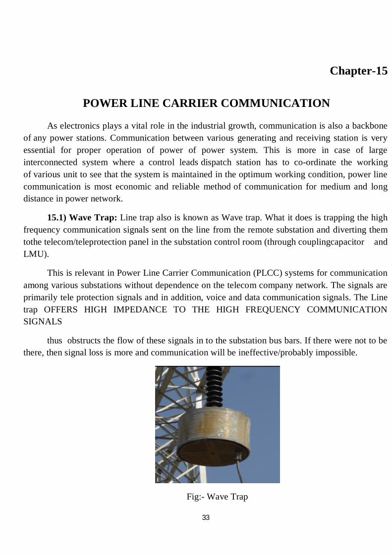
15.1) Wave Trap: Line trap also is known as Wave trap. What it does is trapping the high frequency communication signals sent on the line from the remote substation and diverting them tothe telecom/teleprotection panel in the substation control room (through couplingcapacitor and LMU).
This is relevant in Power Line Carrier Communication (PLCC) systems for communication among various substations without dependence on the telecom company network. The signals are primarily tele protection signals and in addition, voice and data communication signals. The Line trap OFFERS HIGH IMPEDANCE TO THE HIGH FREQUENCY COMMUNICATION SIGNALS
thus obstructs the flow of these signals in to the substation bus bars. If there were not to be there, then signal loss is more and communication will be ineffective/probably impossible.
Fig:- Wave Trap
34
Chapter-16
EARTHING OF THE SYSTEM
The provision of an earthing system for an electric system is necessary by the following reason.
•In the event of over voltage on the system due to lightening discharge or other system fault. These parts of equipment, which are normally dead, as for as voltage, are concerned do not attain dangerously high potential.
•In a three phase, circuit the neutral of the system is earthed in order to stabilize the potential of circuit with respect to earth. The resistance of earthing system is depending on:
•Shape and material of earth electrode used.
•Depth in the soil. Specific resistance of soil surrounding in the neighbourhood of system electrodes.
16.1) PROCEDURE OF EARTHING:-
Technical consideration the current carrying path should have enough capacity to deal with more faults current. The resistance of earth and current path should be low enough to prevent voltage rise between earth and neutral. The earth electrode must be driven in to the ground to a sufficient depth to as to obtain lower value of earth resistance. To sufficient lowered earth resistance a number of electrodes are inserted in the earth to a depth, they are connected together to form a mesh. The resistance of earth should be for the mesh in generally inserted in the earth at 0.5mdepth the several point of mesh then connected to earth electrode or ground conduction. The earth electrode is metal plate copper is used for earth plate.
16.2)NEUTRALEARTHING:
Neutral earthing of powertransformer all power system operates with groundedneutral.Grounding of neutral offers several advantages the neutral point of generator transformer is connected to earth directly or through a reactance in some cases the neutral point is earthed through an adjustable reactor of reactance matched with the line.
•The earth fault protection is based on the method of neutral earthing.
•The neutral earthing is associated switchgear.The neutral earthing is provided for the purpose of protection arcing grounds unbalanced voltages with respect to protection from lightening and for improvement of the system.
35
Chapter-17
BATTERY ROOM
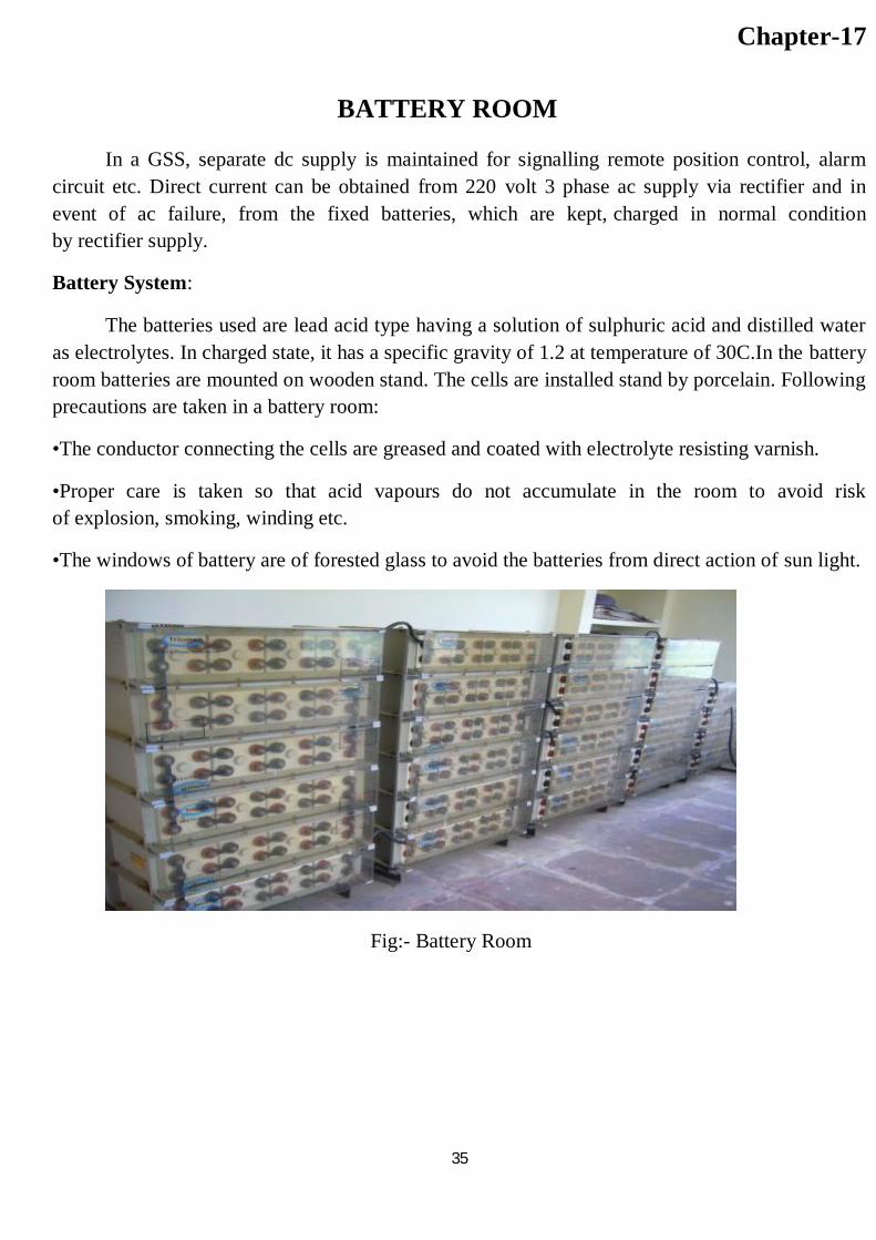
In a GSS, separate dc supply is maintained for signalling remote position control, alarm circuit etc. Direct current can be obtained from 220 volt 3 phase ac supply via rectifier and in event of ac failure, from the fixed batteries, which are kept, charged in normal condition by rectifier supply.
Battery System:
The batteries used are lead acid type having a solution of sulphuric acid and distilled water as electrolytes. In charged state, it has a specific gravity of 1.2 at temperature of 30C.In the battery room batteries are mounted on wooden stand. The cells are installed stand by porcelain. Following precautions are taken in a battery room:
•The conductor connecting the cells are greased and coated with electrolyte resisting varnish.
•Proper care is taken so that acid vapours do not accumulate in the room to avoid risk of explosion, smoking, winding etc.
•The windows of battery are of forested glass to avoid the batteries from direct action of sun light.
Fig:- Battery Room
36
Chapter-18
Some definitions related to transformer
1. ON LOAD TAP CHANGER:-It is a device for changing the tapping connection of windings, suitable for operation, while the transformer is energized or on load. Generally it consists of a diverter switch (with transition impedance) and a tap selector (which can be with or without change over selector).
2. DIVERTER SWITCH:-A switching device used in conjunction with a tap selector to carry, make and break currents in circuits which have already been selected. A diverter switch of spring operated type includes an independent means of storing energy for their operation.
3. TAP SELECTOR:-A device designed to carry, but not to make or break, current used in conjunction with a diverter switch to select tapping connection.
4. SELECTOR SWITCH:-A switching device capable of making, carrying and breaking current, combining the duties of a tap selector and diverter switch.
5. CHANGE OVER SELECTOR:-A device designed to carry, but not to make or break, current used in conjunction with a tap selector or selector switch to enable its contacts and the connected tapping to be used more than once when moving from one extreme position to other.
6. TRANSITION RESISTANCE:-A resistor consisting of one or more units bridging the tapping next to be used for the purpose of transferring load from one tapping to the other without interruptions or appreciable change in the load current and at the same time limiting the circulating current for the period that both tapping are used.
7. DRIVING MECHANISM:-The means by which the drive to the tap changer is actuated.
37
8. MOTOR DRIVE MECHANISM:-A driving mechanism as defined above which incorporates an electric motor and control circuit.
9. STEP BY STEP CONTROL:-Electrical and mechanical devices stopping the motor drive mechanism after completion of a tap change, independently of the operating sequence of the control switch.
10. TAP POSITION INDICATOR:-An electrical and mechanical device for indicating the tap position of the tap changer.
11. TAP CHANGE IN PROGRESS INDICATION:- A device indicating that the motor drive mechanism is running.
12. LIMIT SWITCHES:-Electromechanical devices preventing operation of tap changer beyond either end position, but allowing operation towards the opposite direction.
13. OPERATION COUNTER:-A device indicating the number of tap changes accomplished.
14. MANUAL OPERATION OF MOTOR DRIVE MECHANISM:-Operation of the tap changer manually by a mechanical device, blocking at the same time operation by the electric motor.

38
CONCLUSION
The training at grid substation was very helpful. It has improved my theoretical concepts of electrical power transmission and distribution. Protection of various apparatus was a great thing. Maintenance of transformer, circuit breaker, isolator, insulator, bus bar etc was observable.
I had a chance to see the remote control of the equipments from control room itself, which was very interesting.
So the training was more than hope to me and helped me to understand about power system more.