Embed Size (px)
Citation preview

© 2016 Cisco and/or its affiliates. All rights reserved. This document is Cisco Public. Page 1 of 28
White Paper
Y.1564 Capabilities on the ASR 920
The objective of this document is to provide an in-depth understanding of the
capabilities of ASR 920 platform with respect to Y.1564 service activation. This
document assumes the reader has a basic understanding of Y.1564.
Overview of Y.1564
The ITU-T recommendation Y.1564 defines an out-of-service test methodology to confirm the proper configuration
and performance of an Ethernet service prior to customer delivery and covers the case of both a point-to-point and
point-to-multipoint topology. This service activation acceptance testing of Ethernet-based services can be
implemented as a test function inside of a network element and this is the case examined below - specifically for
the Cisco ASR 920 Aggregation Services Router series of products.
Modes of Operation
There are various modes of operation for Y.1564, namely:
● Traffic generation
● Passive measurement
● Two way statistics collection
In the traffic generation mode, the ASR 920 can generate traffic and send out over the interface on which the
service is to be running. With this capability there is no need for an external traffic generator to test the service
since it is generated internally. In the later portion of this document we examine the range of traffic profiles possible
to generate on ASR 920.
In the passive measurement mode, the router measures the traffic received on an interface. This mode is used to
measure the traffic received at the remote node in order to validate that the service has been configured correctly
in that particular direction. In this mode ASR920 can measure traffic sent by any other traffic generator. It does not
necessarily have to be an ASR920 generating the traffic.
In the two-way statistics collection mode, all measurements are done locally on the sender. The traffic generated
from the local sender is looped back from the remote node (so called “responder” node). For the responder node to

© 2016 Cisco and/or its affiliates. All rights reserved. This document is Cisco Public. Page 2 of 28
be able to return the received traffic back to the sender, a loopback has to be configured and then enabled before
starting the test. There is no requirement of sync in the two-way statistics collection mode.
Traffic generation and measurement
Traffic can be generated as external or internal on ASR920. External here does not mean traffic generated from an
external traffic generator. External traffic generation, also known as facility generation, is the traffic generation from
the NNI interface configured on ASR920 towards the service provider network. It is the egress traffic generated
from the interface.
Internal traffic generation also known as terminal generation is the traffic generation from the UNI interface
configured on the ASR920 towards the service provider network on the NNI interface traversing the forwarding
plane of the node. Internal traffic generation is similar to the traffic received on a UNI interface and then traversing
the forwarding plane of ASR920 and then send out on the NNI interface configured on ASR920.
The traffic that arrives at the far end node can either be measured by configuring passive measurement mode at
the far end node or it can be looped back by configuring and enabling the loopback at the remote node.
The measurement done at the far end node is called the passive mode. In the passive mode there are two ways to
do the measurement, internal and external. External measurement is done on the NNI interface whereas internal
measurement is done on the UNI interface. The traffic measured at the UNI interface with “internal” measurement-
type direction traverses the forwarding plane of ASR920.
For traffic looped at the far end node measurement is done at the local sender node. The measurement direction
must match the traffic generation direction in the IP SLA configuration. This traffic generation and measurement at
the local sender node is called the “two-way statistics collection” mode.
Network Types and Traffic Target Types
The service running on a network could be a Layer-2 or a Layer-3 service.
Within the Layer-2 service activation testing the following traffic target types are supported:
i) Bridge Domains
ii) Service Instance
ASR 920 ASR 920
Layer 2 NNI UNI
Traffic generator
Internal
External
G0/0/1
Te0/0/3
NNI UNI
Responder
External Internal Te0/0/15
Te0/0/14

© 2016 Cisco and/or its affiliates. All rights reserved. This document is Cisco Public. Page 3 of 28
A traffic target type is the type of interface a UNI (User-to-Network Interface) or NNI (Network-to-Network Interface)
is configured as. To explain it further, the traffic can be generated and measured on a bridge domain interface or
service instance interface.
Within the Layer-3 service activation testing the following traffic target types are supported.
i) Physical interface
ii) Service Instance
iii) Bridge Domains
iv) VRF
Another term which will be used extensively in this document is the “traffic direction”. Traffic direction could be
internal or external. The following tables show the different traffic target types and direction supported on ASR920.
Table 1. Layer 2 SLA Target Type and Traffic direction
Target Types Traffic Direction
Service Instance Internal and External
Bridge-domain Internal
Table 2. Layer 3 SLA Target Type and Traffic direction
Target Types Traffic Direction
Physical Interface Internal
Service Instance Internal
Bridge-domain Internal
VRF Internal
Traffic Profiles
The ASR920 has the flexibility to generate the traffic with custom values inside a Layer-2 or Layer-3 packet
header.
Layer-2 traffic profile gives admin the flexibility to configure the following
values:
i. Outer-vlan
ii. Inner-vlan
iii. Outer-cos
iv. Inner-cos
v. Ether-type
vi. Source mac-address
vii. Packet-size (64,128,256,512,1024,1280,1518,9216 and IMIX)
Layer-3 traffic profile gives the admin the flexibility to configure the following values:
IMIX Ratio is
64 bytes 7 packets
512 bytes 4 packets
1518 bytes 1 packet

© 2016 Cisco and/or its affiliates. All rights reserved. This document is Cisco Public. Page 4 of 28
i. Outer-vlan
ii. Source ip-address
iii. Packet-size (64,128,256,512,1024,1280,1518,9216 and IMIX)
iv. DSCP
Y.1564 configuration steps
The following steps are required to configure, enable and verify Y.1564 service activation testing:
i. IP SLA configuration
ii. Loopback configuration and activation (only for two-way statistics collection mode)
iii. IP SLA activation or Test activation
iv. IP SLA Statistics verification
Sample Configuration Layer-2 Traffic
Let us examine the sample configuration for Layer-2 traffic generation, measurement and two-way mode. Two
target types, Service Instance and Bridge Domain, are supported on the ASR920 with color-aware and color-blind
traffic generation.
Traffic generation mode, Target-type Service Instance
IP SLA Configuration
ip sla 1
service-performance type ethernet dest-mac-addr 0011.1111.1111 interface Te0/0/3
service instance 1
frequency iteration 2 delay 1
ASR 920
Layer 2 NNI UNI
Traffic generator
Internal
External
G0/0/1 Te0/0/3

© 2016 Cisco and/or its affiliates. All rights reserved. This document is Cisco Public. Page 5 of 28
profile packet
outer-vlan 10
profile traffic direction external
rate-step kbps 10000
duration time 100
NNI Interface
interface TenGigabitEthernet0/0/3
service instance 1 ethernet
encapsulation dot1q 10
bridge-domain 10
IP SLA Activation
ip sla schedule 1 start-time now
IP SLA Verification
show ip sla statistics 1
IPSLAs Latest Operation Statistics
IPSLA operation id: 1
Type of operation: Ethernet Service Performance
Test mode: Traffic Generator
Steps Tested (kbps): 10000
Test duration: 100 seconds
Latest measurement: *09:11:13.435 UTC Mon Oct 17 2016
Latest return code: Oper End of Life
Step 1 (10000 kbps):
Stats:
Tx Packets: 1885626 Tx Bytes: 120680064
Step Duration: 100 seconds
Traffic generation mode, Target-type Bridge-domain
IP SLA Configuration
ip sla 1
service-performance type ethernet dest-mac-addr 00ab.cdef.1234 bridge-domain 10
profile packet
outer-vlan 10
profile traffic direction internal
rate-step kbps 100000
ip sla schedule 1 start-time now
UNI Interface
interface GigabitEthernet0/0/1
service instance 1 ethernet
encapsulation dot1q 10
bridge-domain 10
NNI Interface
interface TenGigabitEthernet0/0/3
service instance 1 ethernet
encapsulation dot1q 10
bridge-domain 10
Traffic direction
external means the
traffic is generated
from NNI interface
Te0/0/3 towards the
network. For internal
traffic generation use
‘traffic direction
internal’ and interface
Gi0/0/1 instead of
Te0/0/3. Both UNI
and NNI must be in
the same bridge-
domain for internal
traffic generation.
For Target-type bridge-
domain only internal
traffic generation is
supported.

© 2016 Cisco and/or its affiliates. All rights reserved. This document is Cisco Public. Page 6 of 28
IP SLA Activation
ip sla schedule 1 start-time now
IP SLA Verification
IPSLAs Latest Operation Statistics
IPSLA operation id: 1
Type of operation: Ethernet Service Performance
Test mode: Traffic Generator
Steps Tested (kbps): 100000
Test duration: 100 seconds
Latest measurement: *12:36:07.627 UTC Mon Oct 17 2016
Latest return code: Oper End of Life
Step 1 (100000 kbps):
Stats:
Tx Packets: 18864018 Tx Bytes: 1207297152
Step Duration: 100 seconds
Passive mode, Target-type Service-instance
IP SLA Configuration
ip sla 1
service-performance type ethernet dest-mac-addr
0011.1111.1111 interface TenGigabitEthernet0/0/15 service
instance 1
measurement-type direction external
receive
interface TenGigabitEthernet0/0/15
service instance 1 ethernet
encapsulation dot1q 10
bridge-domain 10
IP SLA Activation
ip sla schedule 1 start-time now
IP SLA Verification
NNI UNI
Responder
External Internal Te0/0/15
Te0/0/14
ASR 920
For measuring at UNI
interface measurement-
type direction internal is
used and UNI interface
Te0/0/14 is used instead
of NNI Te0/0/15.
© 2016 Cisco and/or its affiliates. All rights reserved. This document is Cisco Public. Page 7 of 28
#sh ip sla statistics
IPSLAs Latest Operation Statistics
IPSLA operation id: 1
Type of operation: Ethernet Service Performance
Test mode: Passive Measurement
Test duration: 50 seconds
Latest measurement: *16:34:40.389 UTC Thu Sep 8 2016
Latest return code: OK
Stats:
IR(kbps)
5790
Rx Packets: 565692 Rx Bytes: 36204288
Step Duration: 50 seconds
The Rx Packets value must exactly match the transmitted Packets at the generator in order to verify the service
configuration and performance.
Passive mode, Target-type Bridge-domain
IP SLA Configuration
ip sla 1
service-performance type ethernet dest-mac- addr
00ab.cdef.1234 bridge-domain 10
measurement-type direction internal
receive
duration time 50
Interface Configuration
interface TenGigabitEthernet0/0/15
service instance 1 ethernet
encapsulation dot1q 10
bridge-domain 10
interface TenGigabitEthernet0/0/14
service instance 1 ethernet
encapsulation dot1q 10
bridge-domain 10
IP SLA Activation
ip sla schedule 1 start-time now
IP SLA Statistics
sh ip sla statistics
IPSLAs Latest Operation Statistics
IPSLA operation id: 1
Type of operation: Ethernet Service Performance
Test mode: Passive Measurement
Test duration: 50 seconds
Latest measurement: *23:34:24.694 UTC Thu Sep 8 2016
Latest return code: OK
In the target type bridge-
domain only internal traffic
direction is supported

© 2016 Cisco and/or its affiliates. All rights reserved. This document is Cisco Public. Page 8 of 28
Stats:
IR(kbps)
61146
Rx Packets: 5659188 Rx Bytes: 384824784
Step Duration: 50 seconds
Two-way statistics collection mode, Target-type Service Instance
In the two-way statistics collection mode both traffic generation and measurement are done in a single “ip sla”
instance. Both traffic generation and measurement-type must have the same direction either internal or external.
Sample Configuration for Target-type Service Instance, Traffic direction internal, Loopback
internal
Below is the sample configuration of two-way statistics collection mode for traffic generation internal and loopback
internal. In this example, on the traffic generator ASR920 the generated traffic will be directed towards the service-
instance (UNI interface G0/0/1) which is the Target-type and looped back at the UNI Te0/0/14 interface on the
responder ASR920.
Traffic generator
interface GigabitEthernet0/0/1
service instance 1 ethernet
encapsulation dot1q 10
bridge-domain 10
interface TenGigabitEthernet0/0/3
service instance 1 ethernet
encapsulation dot1q 10
bridge-domain 10
ip sla 1
service-performance type ethernet dest-mac-addr 0011.1111.1111 interface
GigabitEthernet0/0/1
service instance 1
frequency iteration 2 delay 1
measurement-type direction internal
delay
jitter
loss
receive
throughput
profile packet
outer-vlan 10
profile traffic direction internal
rate-step kbps 10000
duration time 100
ASR 920 ASR 920
Layer 2 NNI UNI
Traffic generator
Internal G0/0/1 Te0/0/3
NNI UNI
Responder
Internal Loopback Te0/0/14 Te0/0/15
Traffic direction must match
the measurement-type
direction.
Both NNI and UNI must be
in the same bridge domain

© 2016 Cisco and/or its affiliates. All rights reserved. This document is Cisco Public. Page 9 of 28
Responder
interface TenGigabitEthernet0/0/15
service instance 1 ethernet
encapsulation dot1q 10
bridge-domain 10
interface TenGigabitEthernet0/0/14
service instance 1 ethernet
encapsulation dot1q 10
bridge-domain 10
ethernet loopback permit internal
Loopback Activation
ethernet loopback start local interface te0/0/14 service instance 1 internal dot1q
10 timeout none
IP SLA Statistics
R2#sh ip sla statistics 1
IPSLAs Latest Operation Statistics
IPSLA operation id: 1
Type of operation: Ethernet Service Performance
Test mode: Two-way Measurement
Steps Tested (kbps): 100000
Test duration: 100 seconds
Latest measurement: *15:22:11.517 UTC Mon Oct 17 2016
Latest return code: Oper End of Life
Overall Throughput: 99412 kbps
Step 1 (100000 kbps):
Stats:
IR(kbps) FL FLR Avail FTD Min/Avg/Max FDV Min/Avg/Max
99412 0 0.00% 100.00% 137.12us/182.36us/192.96us
10.72us/11.35us/55.76us
Tx Packets: 818613 Tx Bytes: 1242654534
Rx Packets: 818613 Rx Bytes: 1242654534
Step Duration: 100 seconds
Sample Configuration for Target-type Service Instance, Traffic direction external, Loopback
external
Both NNI and UNI must be
in the same bridge domain.

© 2016 Cisco and/or its affiliates. All rights reserved. This document is Cisco Public. Page 10 of 28
Below is the sample configuration of two-way statistics collection mode for traffic generation external and loopback
external. In this example the traffic is generated from the NNI interface Te0/0/3 on the traffic generator ASR920
and looped back at the NNI Te0/0/15 interface on the responder ASR920.
Traffic Generator
ip sla 1
service-performance type ethernet dest-mac-addr 0011.1111.1111 interface Te t0/0/3
service instance 1
frequency iteration 2 delay 1
measurement-type direction external
delay
jitter
loss
receive
throughput
profile packet
outer-vlan 10
packet-size 1518
profile traffic direction external
rate-step kbps 100000
duration time 100
ip sla schedule 1 start-time now
interface TenGigabitEthernet0/0/3
service instance 1 ethernet
encapsulation dot1q 10
bridge-domain 10
Responder
interface TenGigabitEthernet0/0/15
service instance 1 ethernet
encapsulation dot1q 10
bridge-domain 10
ethernet loopback permit external
Loopback activation
ethernet loopback start local interface te0/0/15 service instance 1 external dot1q 10 timeout
none
ASR 920 ASR 920
Layer 2 NNI UNI
Traffic generator
External
G0/0/1
Te0/0/3
NNI UNI
Responder
External Te0/0/15
Te0/0/14

© 2016 Cisco and/or its affiliates. All rights reserved. This document is Cisco Public. Page 11 of 28
Two-way statistics collection mode, Target-type Bridge-domain
In the two-way statistics collection mode both traffic generation and measurement are done in a single “ip sla”
instance. Both traffic generation and measurement-type must have the same direction either internal or external.
Sample Configuration for Target-type Bridge-domain
Below is the sample configuration of two-way statistics collection mode for traffic generation internal and loopback
internal. In this example, on traffic generator ASR920 the traffic generated will be directed towards the Bridge-
Domain 10 which is the Target-type and looped back at the UNI Te0/0/14 interface on the responder ASR920.
Target-type bridge-domain supports only internal traffic generation.
Traffic Generator
IP SLA Configuration
ip sla 1
service-performance type ethernet dest-mac-addr 00ab.cdef.1234 bridge-domain 10
measurement-type direction internal
delay
jitter
loss
receive
throughput
profile packet
outer-vlan 10
profile traffic direction internal
rate-step kbps 100000
Interface configuration
interface GigabitEthernet0/0/1
service instance 1 ethernet
encapsulation dot1q 10
bridge-domain 10
interface TenGigabitEthernet0/0/3
service instance 1 ethernet
encapsulation dot1q 10
bridge-domain 10
ASR 920 ASR 920
Layer 2 NNI UNI
Traffic generator
Internal G0/0/1 Te0/0/3
NNI UNI
Responder
Internal Loopback Te0/0/14 Te0/0/15
Both NNI and UNI must be
in the same bridge-domain.

© 2016 Cisco and/or its affiliates. All rights reserved. This document is Cisco Public. Page 12 of 28
IP SLA Activation
ip sla schedule 1 start-time now
Responder
interface TenGigabitEthernet0/0/15
service instance 1 ethernet
encapsulation dot1q 10
bridge-domain 10
interface TenGigabitEthernet0/0/14
service instance 1 ethernet
encapsulation dot1q 10
bridge-domain 10
ethernet loopback permit internal
Loopback Activation
ethernet loopback start local interface te0/0/14 service instance 1 internal dot1q
10 timeout none
IP SLA Statistics
R2#sh ip sla statistics 1 details
IPSLAs Latest Operation Statistics
IPSLA operation id: 1
Service Performance Operation
Type: ethernet
Destination
MAC Address: 0011.1111.1111
VLAN:
Interface:
Service Instance:
EVC Name:
Duration Time: 100
Interval Buckets: 1
Signature:
Description:
Measurement Type:
throughput, delay, loss, receive
Direction: internal
Color Conform:
COS: Not Set EXP: Not Set DSCP: Not Set
Color Exceed:
COS: Not Set EXP: Not Set DSCP: Not Set
Color Violate:
COS: Not Set EXP: Not Set DSCP: Not Set
Profile Traffic:
Direction: internal
CIR: 0
EIR: 0
CBS: 0
EBS: 0
Burst Size: 0
Burst Duration: 0
Inter Burst Interval: 0
Loopback configured on the
UNI

© 2016 Cisco and/or its affiliates. All rights reserved. This document is Cisco Public. Page 13 of 28
Rate Step (kbps): 100000
Profile Packet[0] :
Inner COS: Not Set
Outer COS: Not Set
Inner VLAN: Not Set
Outer VLAN: 10
DSCP: default
Packet Size: 1518
Source MAC Address: Not Set
EtherType: default
Number of Packets: 100
Type of operation: Ethernet Service Performance
Test mode: Two-way Measurement
Steps Tested (kbps): 100000
Test duration: 100 seconds
Latest measurement: *18:48:50.849 UTC Mon Oct 17 2016
Latest return code: Oper End of Life
Overall Throughput: 99412 kbps
Step 1 (100000 kbps):
Stats:
IR(kbps) FL FLR Avail FTD Min/Avg/Max
99412 0 0.00% 100.00% 133.68us/178.86us/190.48us
Tx Packets: 818613 Tx Bytes: 1242654534
Rx Packets: 818613 Rx Bytes: 1242654534
Step Duration: 100 seconds
Sample Configuration Layer-3 Traffic
Let us examine the sample configuration for Layer-3 traffic generation, measurement, and two-way mode. The four
target types supported on ASR920 traffic generation are Physical interface, Service Instance, Bridge Domain and
VRF. With Layer-3, only internal traffic generation and measurement are supported. Also, the loopback direction
supported on the responder is internal only.
ASR 920 ASR 920
Layer 3 NNI UNI
Traffic generator
Internal G0/0/1 Te0/0/3
NNI UNI
Responder
Internal Te0/0/15 Te0/0/14

© 2016 Cisco and/or its affiliates. All rights reserved. This document is Cisco Public. Page 14 of 28
Two-way statistics collection mode, Target-type Service-instance
In the two-way statistics collection mode both traffic generation and measurement type are done in a single “ip sla”
instance. Both traffic generation and measurement-type must be internal because only internal mode of traffic
generation is supported in Layer-3.
Sample Configuration for Target-type Service Instance
Traffic Generator
IP SLA Configuration
ip sla 1
service-performance type ip dest-ip-addr 20.1.1.1 interface GigabitEthernet0/0/1
service instance 1
frequency iteration 1 delay 1
measurement-type direction internal
delay
jitter
loss
receive
throughput
profile packet
source-ip-addr 30.1.1.1
outer-vlan 10
profile traffic direction internal
rate-step kbps 10000
duration time 100
Interface configuration interface TenGigabitEthernet0/0/3
service instance 1 ethernet
encapsulation dot1q 10
rewrite ingress tag pop 1 symmetric
bridge-domain 11
interface GigabitEthernet0/0/1
service instance 1 ethernet
encapsulation dot1q 10
rewrite ingress tag pop 1 symmetric
bridge-domain 10
interface BDI10
ip address 30.1.1.1 255.255.255.0
interface BDI11
ip address 192.168.1.2 255.255.255.0
Responder
Loopback configuration ip sla 1
service-performance type ip dest-ip-addr 20.1.1.1 interface
TenGigabitEthernet0/0/14 service instance 1
frequency iteration 1 delay 1
loopback direction internal
profile packet
source-ip-addr 30.1.1.1
outer-vlan 10
duration time 1000
In Layer-3 mode, loopback
on the responder is
configured within IP SLA
configuration
Same source-ip and
destination-ip must be used
in the responder IP SLA
configuration

© 2016 Cisco and/or its affiliates. All rights reserved. This document is Cisco Public. Page 15 of 28
Interface configuration interface TenGigabitEthernet0/0/15
service instance 1 ethernet
encapsulation dot1q 10
rewrite ingress tag pop 1 symmetric
bridge-domain 10
interface TenGigabitEthernet0/0/14
service instance 1 ethernet
encapsulation dot1q 10
rewrite ingress tag pop 1 symmetric
bridge-domain 11
interface BDI10
ip address 192.168.1.1 255.255.255.0
interface BDI11
ip address 20.1.1.1 255.255.255.0
IP SLA Statistics
R2#sh ip sla statistics
IPSLAs Latest Operation Statistics
IPSLA operation id: 1
Test mode: Two-way Measurement
Steps Tested (kbps): 100000
Test duration: 100 seconds
Latest measurement: *17:51:36.214 UTC Thu Oct 13 2016
Latest return code: Oper End of Life
Overall Throughput: 96583 kbps
Step 1 (100000 kbps):
Stats:
IR(kbps) FL FLR Avail FTD Min/Avg/Max FDV Min/Avg/Max
96583 0 0.00% 100.00% 29.76us/58.66us/94.44us 160ns/890ns/64.52us
Tx Packets: 18864018 Tx Bytes: 1207297152
Rx Packets: 18864018 Rx Bytes: 1207297152
Step Duration: 100 seconds
Sample Configuration for Target-type Bridge-domain
Traffic Generator
IP SLA Configuration ip sla 1
service-performance type ip dest-ip-addr 20.1.1.1 bridge-domain 10
frequency iteration 1 delay 1
measurement-type direction internal
delay
jitter
loss
receive
throughput
profile packet
source-ip-addr 30.1.1.1
profile traffic direction internal
rate-step kbps 100000
duration time 100

© 2016 Cisco and/or its affiliates. All rights reserved. This document is Cisco Public. Page 16 of 28
IP SLA Activation ip sla schedule 1 start-time now
Interface Configuration
NNI Interface interface TenGigabitEthernet0/0/3
ip address 192.168.1.2 255.255.255.0
UNI Interface interface GigabitEthernet0/0/1
service instance 1 ethernet
encapsulation dot1q 10
rewrite ingress tag pop 1 symmetric
bridge-domain 10
interface BDI10
ip address 30.1.1.1 255.255.255.0
Responder Loopback configuration ip sla 1
service-performance type ip dest-ip-addr 20.1.1.1 bridge-domain 10
frequency iteration 1 delay 1
loopback direction internal
profile packet
source-ip-addr 30.1.1.1
duration time 1000
IP SLA Activation or loopback activation on responder ip sla schedule 1 start-time now
Interface configuration
NNI Interface interface TenGigabitEthernet0/0/15
ip address 192.168.1.1 255.255.255.0
UNI Interface interface TenGigabitEthernet0/0/14
no ip address
service instance 1 ethernet
encapsulation dot1q 10
rewrite ingress tag pop 1 symmetric
bridge-domain 10
interface BDI10
ip address 20.1.1.1 255.255.255.0
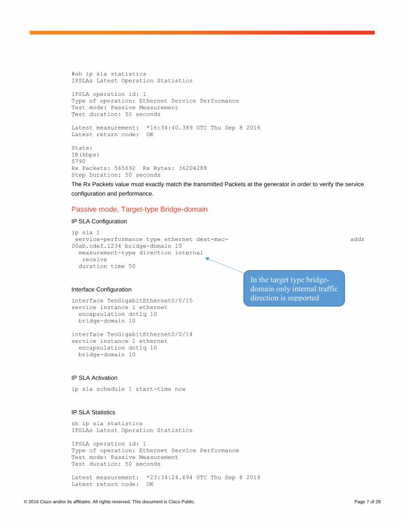
IP SLA Statistics
sh ip sla statistics details
IPSLAs Latest Operation Statistics
IPSLA operation id: 1
Service Performance Operation
Type: ip
Destination
Destination address: 20.1.1.1
VLAN:
Layer-3 loopback on the
responder is configured
within IP SLA configuration
© 2016 Cisco and/or its affiliates. All rights reserved. This document is Cisco Public. Page 17 of 28
Interface:
Service Instance:
EVC Name:
Duration Time: 100
Interval Buckets: 1
Signature:
Description:
Measurement Type:
throughput, delay, jitter, loss, receive
Direction: internal
Color Conform:
COS: Not Set EXP: Not Set DSCP: Not Set
Color Exceed:
COS: Not Set EXP: Not Set DSCP: Not Set
Color Violate:
COS: Not Set EXP: Not Set DSCP: Not Set
Profile Traffic:
Direction: internal
CIR: 0
EIR: 0
CBS: 0
EBS: 0
Burst Size: 0
Burst Duration: 0
Inter Burst Interval: 0
Rate Step (kbps): 100000
Profile Packet[0] :
Source IP: 30.1.1.1
Tunnel EXP: Not Set
Packet Size: Not Set
Outer VLAN: Not Set
Number of Packets: 100
Test mode: Two-way Measurement
Steps Tested (kbps): 100000
Test duration: 100 seconds
Latest measurement: *22:44:22.630 UTC Thu Oct 13 2016
Latest return code: Oper End of Life
Overall Throughput: 96583 kbps
Step 1 (100000 kbps):
Stats:
IR(kbps) FL FLR Avail FTD Min/Avg/Max FDV Min/Avg/Max
96583 0 0.00% 100.00% 28.96us/58.09us/61.12us 80ns/839ns/31.84us
Tx Packets: 18864018 Tx Bytes: 1207297152
Rx Packets: 18864018 Rx Bytes: 1207297152
Step Duration: 100 seconds
Sample Configuration for Target-type Physical Interface
Traffic Generator
IP SLA Configuration ip sla 1
service-performance type ip dest-ip-addr 20.1.1.1 interface GigabitEthernet0/0/1
frequency iteration 1 delay 1
measurement-type direction internal
delay
jitter
loss
receive
throughput
profile packet

© 2016 Cisco and/or its affiliates. All rights reserved. This document is Cisco Public. Page 18 of 28
source-ip-addr 30.1.1.1
profile traffic direction internal
rate-step kbps 10000
duration time 100
IP SLA Activation ip sla schedule 1 start-time now
Interface Configuration interface TenGigabitEthernet0/0/3
ip address 192.168.1.2 255.255.255.0
interface GigabitEthernet0/0/1
ip address 30.1.1.1 255.255.255.0
Responder
Loopback configuration ip sla 1
service-performance type ip dest-ip-addr 20.1.1.1 interface
TenGigabitEthernet0/0/14
frequency iteration 1 delay 1
loopback direction internal
profile packet
source-ip-addr 30.1.1.1
duration time 1000
Loopback activation ip sla schedule 1 start-time now
Interface configuration interface TenGigabitEthernet0/0/15
ip address 192.168.1.1 255.255.255.0
interface TenGigabitEthernet0/0/14
ip address 20.1.1.1 255.255.255.0
IP SLA Statistics
sh ip sla statistics
IPSLAs Latest Operation Statistics
IPSLA operation id: 1
Test mode: Two-way Measurement
Steps Tested (kbps): 10000
Test duration: 100 seconds
Latest measurement: *11:12:05.192 UTC Thu Aug 25 2016
Latest return code: Oper End of Life
Overall Throughput: 9654 kbps
Step 1 (10000 kbps):
Stats:
IR(kbps) FL FLR Avail FTD Min/Avg/Max FDV Min/Avg/Max
9654 0 0.00% 100.00% 28.96us/30.52us/67.00us
240ns/1.11us/37.88us
Tx Packets: 1885626 Tx Bytes: 120680064
Rx Packets: 1885626 Rx Bytes: 120680064
Step Duration: 100 seconds
Sample Configuration for Target-type VRF
Traffic Generator

© 2016 Cisco and/or its affiliates. All rights reserved. This document is Cisco Public. Page 19 of 28
IP SLA Configuration ip sla 1
service-performance type ip dest-ip-addr 20.1.1.1 vrf 4
frequency iteration 2 delay 1
measurement-type direction internal
delay
loss
receive
throughput
profile packet
source-ip-addr 30.1.1.1
profile traffic direction internal
rate-step kbps 100000
duration time 100
IP SLA Activation ip sla schedule 1 start-time now
Interface configuration interface TenGigabitEthernet0/0/3
vrf forwarding 1564
ip address 192.168.1.2 255.255.255.0
interface GigabitEthernet0/0/1
vrf forwarding 1564
ip address 30.1.1.1 255.255.255.0
Responder Loopback configuration ip sla 1
service-performance type ip dest-ip-addr 20.1.1.1 vrf 3
frequency iteration 1 delay 1
loopback direction internal
profile packet
source-ip-addr 30.1.1.1
duration time 1000
Loopback Activation ip sla schedule 1 start-time now
Interface Configuration interface TenGigabitEthernet0/0/15
vrf forwarding 1564
ip address 192.168.1.1 255.255.255.0
interface TenGigabitEthernet0/0/14
vrf forwarding 1564
ip address 20.1.1.1 255.255.255.0
IP SLA Statistics sh ip sla statistics 1
IPSLAs Latest Operation Statistics
IPSLA operation id: 1
Test mode: Two-way Measurement
Steps Tested (kbps): 100000
Test duration: 100 seconds
Latest measurement: *01:45:32.818 UTC Tue Oct 18 2016
Latest return code: Oper End of Life
This is VRF ID
© 2016 Cisco and/or its affiliates. All rights reserved. This document is Cisco Public. Page 20 of 28
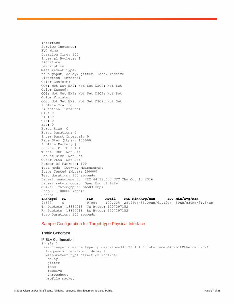
Overall Throughput: 96583 kbps
Step 1 (100000 kbps):
Stats:
IR(kbps) FL FLR Avail FTD Min/Avg/Max
96583 0 0.00% 100.00% 28.96us/58.09us/61.12us
Tx Packets: 18864018 Tx Bytes: 1207297152
Rx Packets: 18864018 Rx Bytes: 1207297152
Step Duration: 100 seconds
Interop with ASR9K
There could be scenarios where ASR920 is the traffic generator and ASR9K is the responder.
In this test the loopback is configured on ASR9K 8x100GE card.
Traffic Generator IP SLA Configuration ip sla 1
service-performance type ethernet dest-mac-addr 5897.bd26.b39a interface
TenGigabitEthernet0/0/26 service instance 1
frequency iteration 1 delay 1
measurement-type direction external
delay
jitter
loss
receive
throughput
profile packet
outer-vlan 10
src-mac-addr 5897.bd26.b39a
profile traffic direction external
rate-step kbps 100000
duration time 100
IP SLA Activation ip sla schedule 1 start-time now
Interface Configuration interface TenGigabitEthernet0/0/26
ASR 920 ASR9K
Layer 2 NNI
Traffic generator
External
Te0/0/26
NNI UNI
Responder
External Te0/1/0/1/5
The dest-mac-addr
and src-mac-addr
must match the
NNI interface of
the generator. In
this case Te0/0/26
© 2016 Cisco and/or its affiliates. All rights reserved. This document is Cisco Public. Page 21 of 28
service instance 1 ethernet
encapsulation dot1q 10
bridge-domain 10
Responder interface TenGigE0/1/0/1/5
loopback line
IP SLA Statistics #sh ip sla statistics
IPSLAs Latest Operation Statistics
IPSLA operation id: 1
Type of operation: Ethernet Service Performance
Test mode: Two-way Measurement
Steps Tested (kbps): 100000
Test duration: 100 seconds
Latest measurement: 01:30:26.895 UTC Wed Nov 16 2016
Latest return code: Oper End of Life
Overall Throughput: 96583 kbps
Step 1 (100000 kbps):
Stats:
IR(kbps) FL FLR Avail FTD Min/Avg/Max FDV Min/Avg/Max
96583 0 0.00% 100.00% 9.90us/42.55us/4294.95ms
160ns/858ns/4294.94ms
Tx Packets: 18864018 Tx Bytes: 1207297152
Rx Packets: 18864018 Rx Bytes: 1207297152
Step Duration: 100 seconds
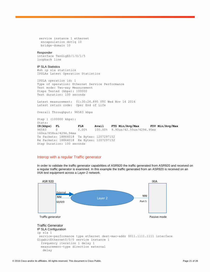
Interop with a regular Traffic generator
In order to validate the traffic generator capabilities of ASR920 the traffic generated from ASR920 and received on a regular traffic generator is examined. In this example the traffic generated from an ASR920 is received on an IXIA test equipment across a Layer-2 network.
Traffic Generator IP SLA Configuration ip sla 1
service-performance type ethernet dest-mac-addr 0011.1111.1111 interface
GigabitEthernet0/0/0 service instance 1
frequency iteration 1 delay 1
measurement-type direction external
delay
ASR 920 IXIA
Layer 2 NNI
Traffic generator
External
G0/0/0
NNI
Passive mode
Port 5

© 2016 Cisco and/or its affiliates. All rights reserved. This document is Cisco Public. Page 22 of 28
jitter
loss
receive
throughput
profile packet
outer-vlan 10
profile traffic direction internal
rate-step pps 100
duration time 100
IP SLA Activation ip sla schedule 1 start-time now
The below screen shot shows the IXIA stats matching the ip sla stats on ASR920.
In order to validate the traffic measuring capabilities of ASR920 the traffic sent from a regular traffic generator and received on an ASR920 in passive mode is examined. In this example the traffic generated from an IXIA test equipment is received on an ASR920 across a Layer-2 network.

© 2016 Cisco and/or its affiliates. All rights reserved. This document is Cisco Public. Page 23 of 28
ASR920 Passive mode ip sla 1
service-performance type ethernet dest-mac-addr 00ab.cdef.1234 bridge-domain 10
measurement-type direction internal
receive
duration time 50
IP SLA Activation ip sla schedule 1 start-time now
The below screen shot shows the IXIA stats matching the ip sla stats on ASR920.
IXIA ASR 920
Layer 2 NNI
Traffic generator
External
G0/0/0
NNI
Passive mode
Port 5

© 2016 Cisco and/or its affiliates. All rights reserved. This document is Cisco Public. Page 24 of 28
Color-Aware Mode
The color mode allows the customer to pre-mark their traffic with a priority tag rather than letting the service
provider blindly enforce the CIR/EIR/CBS/EBS algorithm on the traffic.
The ASR920 has the capability to generate color-aware traffic. For example, the traffic generated can be
configured with 100Mbps CIR with priority tag 5 and 50Mbps EIR with priority tag 4 in order to validate the QoS
performance and configurations for a specific service.
In the color-blind mode, the ASR920 generates the traffic without any priority tagging and the network will treat all
ingress traffic equally and enforce the CIR, EIR, CBS, EBS values blindly.
Color-aware mode is supported for both Layer-2 and Layer-3 traffic generations and measurements. Only internal traffic generation and measurement are supported in color-aware mode.
Sample Configuration Layer-2 Traffic Color-Aware
Target-type Service-instance
Traffic Generator
ip sla 1
service-performance type ethernet dest-mac-addr 0011.1111.1111 interface
GigabitEthernet0/0/1 service instance 1
frequency iteration 1 delay 1
measurement-type direction internal conform-color cos 4 exceed-color cos 5
delay
loss
receive
throughput
profile packet
outer-vlan 10
packet-size 1518
profile traffic direction internal
cir 100000
eir 50000
rate-step kbps 200000
conform-color set-cos-transmit 4
exceed-color set-cos-transmit 5
duration time 100
UNI Interface interface GigabitEthernet0/0/1
service instance 1 ethernet
encapsulation dot1q 10
rewrite ingress tag pop 1 symmetric
bridge-domain 10
NNI Interface interface TenGigabitEthernet0/0/3
service instance 1 ethernet
encapsulation dot1q 10
rewrite ingress tag pop 1 symmetric
bridge-domain 10
IP SLA Activation ip sla schedule 1 start-time now
The commands in the
bold are used to
configure the color
aware mode in the IP
SLA configuration.
© 2016 Cisco and/or its affiliates. All rights reserved. This document is Cisco Public. Page 25 of 28
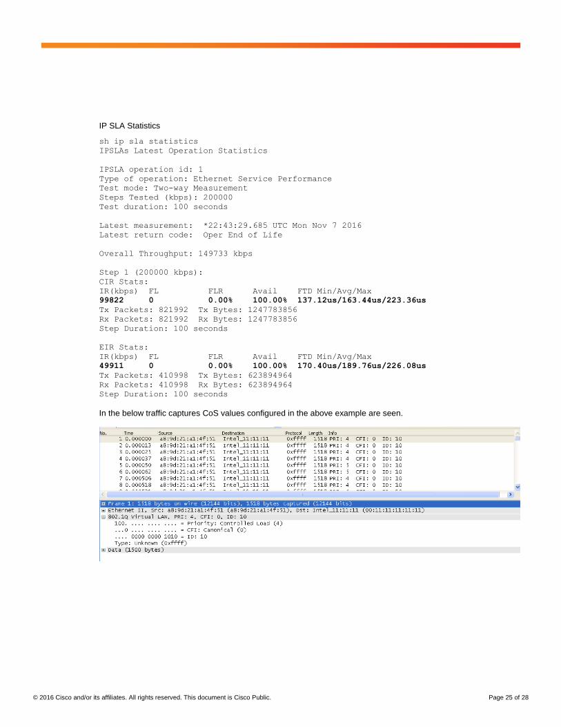
IP SLA Statistics
sh ip sla statistics
IPSLAs Latest Operation Statistics
IPSLA operation id: 1
Type of operation: Ethernet Service Performance
Test mode: Two-way Measurement
Steps Tested (kbps): 200000
Test duration: 100 seconds
Latest measurement: *22:43:29.685 UTC Mon Nov 7 2016
Latest return code: Oper End of Life
Overall Throughput: 149733 kbps
Step 1 (200000 kbps):
CIR Stats:
IR(kbps) FL FLR Avail FTD Min/Avg/Max
99822 0 0.00% 100.00% 137.12us/163.44us/223.36us
Tx Packets: 821992 Tx Bytes: 1247783856
Rx Packets: 821992 Rx Bytes: 1247783856
Step Duration: 100 seconds
EIR Stats:
IR(kbps) FL FLR Avail FTD Min/Avg/Max
49911 0 0.00% 100.00% 170.40us/189.76us/226.08us
Tx Packets: 410998 Tx Bytes: 623894964
Rx Packets: 410998 Rx Bytes: 623894964
Step Duration: 100 seconds
In the below traffic captures CoS values configured in the above example are seen.

© 2016 Cisco and/or its affiliates. All rights reserved. This document is Cisco Public. Page 26 of 28
Sample Configuration Layer-3 Traffic Color-Aware
Target-type Bridge-domain
Traffic Generator ip sla 1
service-performance type ip dest-ip-addr 20.1.1.1 bridge-domain 10
frequency iteration 1 delay 1
measurement-type direction internal conform-color dscp ef exceed-color dscp af11
delay
jitter
loss
receive
throughput
profile packet
source-ip-addr 30.1.1.1
profile traffic direction internal
cir 200000
eir 200000
rate-step kbps 400000
conform-color set-dscp-transmit ef
exceed-color set-dscp-transmit af11
duration time 100
IP SLA Statistics #sh ip sla statistics
IPSLAs Latest Operation Statistics
IPSLA operation id: 1
Test mode: Two-way Measurement
Steps Tested (kbps): 400000
Test duration: 100 seconds
Latest measurement: *14:27:16.636 UTC Mon Nov 7 2016
Latest return code: Oper End of Life
Overall Throughput: 386144 kbps
Step 1 (400000 kbps):
The only
difference
from the color
blind mode are
the commands
in bold.

© 2016 Cisco and/or its affiliates. All rights reserved. This document is Cisco Public. Page 27 of 28
CIR Stats:
IR(kbps) FL FLR Avail FTD Min/Avg/Max FDV Min/Avg/Max
199644 0 0.00% 100.00% 28.96us/140.03us/144.72us
0ns/1.19us/115.68us
Tx Packets: 38993114 Tx Bytes: 2495559296
Rx Packets: 38993114 Rx Bytes: 2495559296
Step Duration: 100 seconds
EIR Stats:
IR(kbps) FL FLR Avail FTD Min/Avg/Max FDV Min/Avg/Max
186500 0 0.00% 100.00% 62.64us/139.78us/144.96us 0ns/643ns/81.84us
Tx Packets: 36425827 Tx Bytes: 2331252928
Rx Packets: 36425827 Rx Bytes: 2331252928
Step Duration: 100 seconds
Above EIR Stats:
IR(kbps) FL FLR Avail FTD Min/Avg/Max FDV Min/Avg/Max
0 0 0.00% 0.00% 0ns/0ns/0ns 0ns/0ns/0ns
Tx Packets: 0 Tx Bytes: 0
Rx Packets: 0 Rx Bytes: 0
Step Duration: 100 seconds
In the below traffic capture the DSCP marking of EF can be seen.

© 2016 Cisco and/or its affiliates. All rights reserved. This document is Cisco Public. Page 28 of 28
In the below traffic capture the DSCP marking of AF11 can be seen.
Throughput measurement for each packet size
The table below shows the maximum SLA rate supported by the ASR920 and it is independent of SLA sessions. Max Rate can be achieved in a single SLA session or combination of two or more SLA sessions.
Packet Size (Bytes) Max Rate (kbps)
64 469848
128 638061
256 775123
512 867758
1024 922728
1280 934554
1518 942124
9216 977675
IMIX 788000
References and Further Information
ITU-T Recommendation Y.1564:
https://www.itu.int/rec/T-REC-Y.1564/en
ASR 920 Series Aggregation Services Router
http://www.cisco.com/c/en/us/products/routers/asr-920-series-aggregation-services-router/index.html
IP SLA Configuration guide
http://www.cisco.com/c/en/us/td/docs/routers/asr920/configuration/guide/ipsla/sla-xe-3s-book-asr920/sla-xe-3s-
book-asr920_chapter_0110.html