Embed Size (px)
Citation preview

XVision
Text-Display-PLC XSystem Device Description
Moeller GmbH! Hein-Moeller-Str. 7-11! D-53115 Bonn ! Germany Tel. +49(0) 228/602-0 ! Fax +49(0) 228/602-2433 www.moeller.net ! [email protected]
XVC-100
For Immediate Delivery call KMParts.com at (866) 595-9616

2
Copyright
Keep documentation for future use!
This documentation is the intellectual property of Moeller GmbH, which also has the exclusive copyright. Any modification of the content, duplication or reprinting of this documentation, as well as any distribution to third parties can only be made with the express permission of Moeller GmbH.
Moeller GmbH does not accept any liability for damages arising from the use of any incorrect or incomplete information contained in this documentation or any information missing therefrom. Moeller GmbH reserves the right to make complete or partial modifications to this document.
All brand and product names are trademarks or registered trademarks of the owner concerned.
For Immediate Delivery call KMParts.com at (866) 595-9616
Device Description XVC-100 Text Display PLC XVC-100 Proper use
Subject to technical modifications Doc No. 92 23 100000 (06/2002) © by Moeller GmbH
3
Proper use The device must only be used for the applications specified in the device description and only in conjunction with the components recommended by Moeller GmbH.
Warning Trouble-free and safe operation of the product can only be ensured if the measures relating to proper transport, storage, assembly, installation and careful operation are strictly observed. The device must not be switched on when it is covered with condensation. When changing its location from cold to warm allow the device to acclimatise to the new conditions before commissioning. No warranty claims will be recognised for faults arising from the improper handling of the device. The device should not be used for the implementation of any safety functions relating to the protection of personnel and machinery. No liability is accepted for claims for damages arising from a failure or functional defect in the device. All data specified in this document does not represent guaranteed specifications in the legal sense.
For Immediate Delivery call KMParts.com at (866) 595-9616

XVC-100 Text Display PLC Device Description XVC-100 Proper use
Subject to technical modifications Doc No. 92 23 100000 (06/2002)
© by Moeller GmbH
4
Safety instructions for the user This device description contains the information required for the proper use of the products described therein. Sections 1 to 11 address technically qualified personnel and Section 12 onwards addresses personnel not requiring any technical knowledge. Qualified personnel in the sense of the safety instructions given in this device description or on the project itself are persons who: as engineering personnel are either familiar with the safety concepts of automation, or as operating personnel, are instructed in the use of automation components and are familiar with the contents of this device description relating to the operation of the device, or as commissioning or service personnel are suitably trained for the repair of automation devices and are authorised to commission circuits and device/systems in accordance with standard safety engineering principles.
For Immediate Delivery call KMParts.com at (866) 595-9616

Device Description XVC-100 Text Display PLC XVC-100 Contents
Subject to technical modifications Doc No. 92 23 100000 (06/2002) © by Moeller GmbH
5
Contents
1 Explanation of symbols............................................................................................ 7 2 Introduction ............................................................................................................... 9 3 Device versions....................................................................................................... 11
3.1 Specifications.....................................................................................................................11 3.2 Accessories........................................................................................................................12 3.3 Designing...........................................................................................................................12
4 Features ................................................................................................................... 13 4.1 Utilisation of the CAN identifier (CANopen) .......................................................................14
5 Commissioning ....................................................................................................... 15 5.1 Overview of connections....................................................................................................15 5.2 Inserting the battery ...........................................................................................................16 5.3 Connecting the power supply.............................................................................................17 5.4 Preparing the shield connections.......................................................................................18 5.5 Connecting the programming interface X7 .....................................................................19 5.6 Connection of the digital input / output - Connector X 1 ....................................................20 5.7 Connection of the digital output - Connector X 2 ...............................................................21 5.8 Connection of the digital input - Connector X 3 .................................................................22 5.9 Connection of the analog input / output - Connector X 4 ...................................................24 5.10 Connection of the CAN interface - Connector X 6...........................................................26 5.11 Inserting the CompactFlash.........................................................................................29 5.12 Function and control LEDs ..............................................................................................30 5.13 Membrane keyboard........................................................................................................31
6 Operation ................................................................................................................. 33 6.1 Startup behaviour...............................................................................................................33 6.2 Shutdown behaviour ..........................................................................................................33 6.3 PLC operating states .........................................................................................................34 6.4 Changing operating mode..................................................................................................35 6.5 Startup behaviour/startup...................................................................................................36 6.6 Program transfer ................................................................................................................37 6.7 System settings..................................................................................................................38
7 Mounting instructions ............................................................................................ 41 7.1 General mounting instructions ...........................................................................................41 7.2 Mounting in the front panel ................................................................................................42 7.3 Front cutout........................................................................................................................43 7.4 Mechanical dimensions......................................................................................................44
8 Display, backlight, contrast ................................................................................... 45 8.1 Contrast .............................................................................................................................45 8.2 Backlight ............................................................................................................................45
9 Diagnostics.............................................................................................................. 45 10 Maintenance and repair .......................................................................................... 47 11 Technical data ......................................................................................................... 49 12 Disposal ................................................................................................................... 53 13 EC Conformity......................................................................................................... 53 14 Revision history ...................................................................................................... 55
For Immediate Delivery call KMParts.com at (866) 595-9616

XVC-100 Text Display PLC Device Description XVC-100 Contents
Subject to technical modifications Doc No. 92 23 100000 (06/2002)
© by Moeller GmbH
6
15 Appendix, Font........................................................................................................ 57 16 Alphabetical index .................................................................................................. 59
For Immediate Delivery call KMParts.com at (866) 595-9616
Device Description XVC-100 Text Display PLC XVC-100 Explanation of symbols
Subject to technical modifications Doc No. 92 23 100000 (06/2002) © by Moeller GmbH
7
1 EXPLANATION OF SYMBOLS
Danger warnings
The following information is for your personal safety and the prevention of damage to the device described or connected devices.
Safety instructions and warnings for the prevention of danger to the life and health of users or service personnel, and for the prevention of damage are highlighted in this document by the following pictograms. Warning and Information pictograms are shown in this document.
Warnings indicate the following: Death, serious injury or substantial material damage may occur if the related safety measures are not implemented.
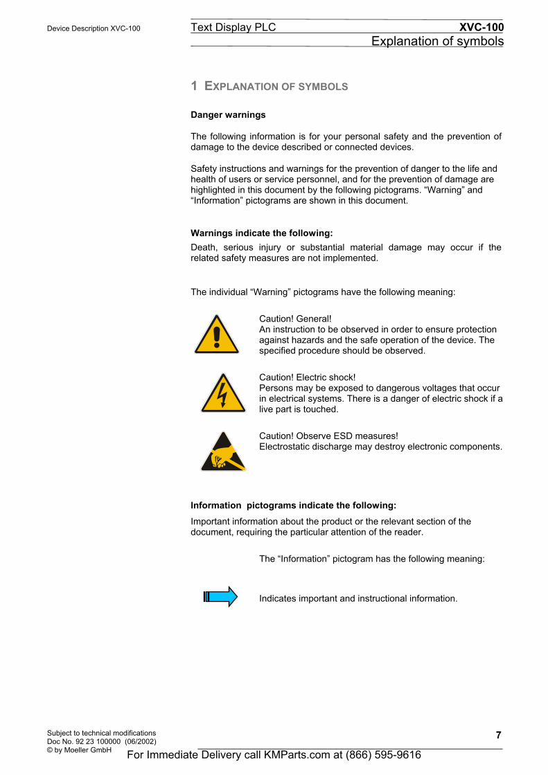
The individual Warning pictograms have the following meaning:
Caution! General! An instruction to be observed in order to ensure protection against hazards and the safe operation of the device. The specified procedure should be observed.
Caution! Electric shock! Persons may be exposed to dangerous voltages that occur in electrical systems. There is a danger of electric shock if a live part is touched.
Caution! Observe ESD measures! Electrostatic discharge may destroy electronic components.
Information pictograms indicate the following: Important information about the product or the relevant section of the document, requiring the particular attention of the reader.
The Information pictogram has the following meaning:
Indicates important and instructional information.
For Immediate Delivery call KMParts.com at (866) 595-9616

XVC-100 Text Display PLC Device Description XVC-100 Explanation of symbols
Subject to technical modifications Doc No. 92 23 100000 (06/2002)
© by Moeller GmbH
8
For Immediate Delivery call KMParts.com at (866) 595-9616

Device Description XVC-100 Text Display PLC XVC-100 Introduction
Subject to technical modifications Doc No. 92 23 100000 (06/2002) © by Moeller GmbH
9
2 INTRODUCTION Advantages of the XVC-100 devices • 8x20 or 4x10 CHARACTER TEXT DISPLAY WITH VARIABLE FONT
• MEMBRANE KEYBOARD WITH 28 KEYS AND 3 LEDs
• INTEGRATED INPUTS/OUTPUTS
• CANopen STANDARD FIELDBUS INTERFACE
• EXCHANGEABLE COMPACTFLASH
• PROGRAMMABLE TO IEC61131 (IL, LD, FBD, SFC, ST, CFC)
• IP65 FRONT
The XVC-100 series text display PLC combines in one device a text display operator panel with a powerful compact PLC. This future-oriented device concept creates wide range of automation and networking options. A compact and fully-fledged PLC with digital and analog inputs and outputs is provided behind the membrane keyboard with the 8x20 character display. Remote peripheral devices can be connected via the integrated CAN bus. All plugs are accessible from the rear. The PLC is programmed in compliance with the IEC61131 industrial standard, thus making the XVC-100 text display PLC into a universal device for automation tasks. A user-friendly PLC function library is provided for designing the visualization functions simply and effectively. The integration of third-party systems (I/Os, drives etc.) via standard fieldbus interfaces (CANopen) and their integration in the overall system offers access to a wide range of process optimised peripheral components. Application range The XVC-100 series text display PLC is designed for controlling, operating and monitoring machines and plants. The rugged and compact design allows the implementation of applications that were previously impossible due to the prohibitive space and cost requirements involved. The high degree of protection (front IP65) and the omission of any moving parts (hard disks, fans) makes the devices ideal for robust use in rugged industrial environments directly at the machine. The devices can be installed in control panels or control desks without any problem. This device description is a reference for the technical data, installation, terminals, commissioning, operation, and maintenance of all XVC-100 versions. The illustrations in this document are for the XVC-100 device version (" Section 3), unless otherwise stated. The designation and function of the connections and signals are the same for all versions.
For Immediate Delivery call KMParts.com at (866) 595-9616

XVC-100 Text Display PLC Device Description XVC-100 Introduction
Subject to technical modifications Doc No. 92 23 100000 (06/2002)
© by Moeller GmbH
10
For Immediate Delivery call KMParts.com at (866) 595-9616
Device Description XVC-100 Text Display PLC XVC-100 Device versions
Subject to technical modifications Doc No. 92 23 100000 (06/2002) © by Moeller GmbH
11
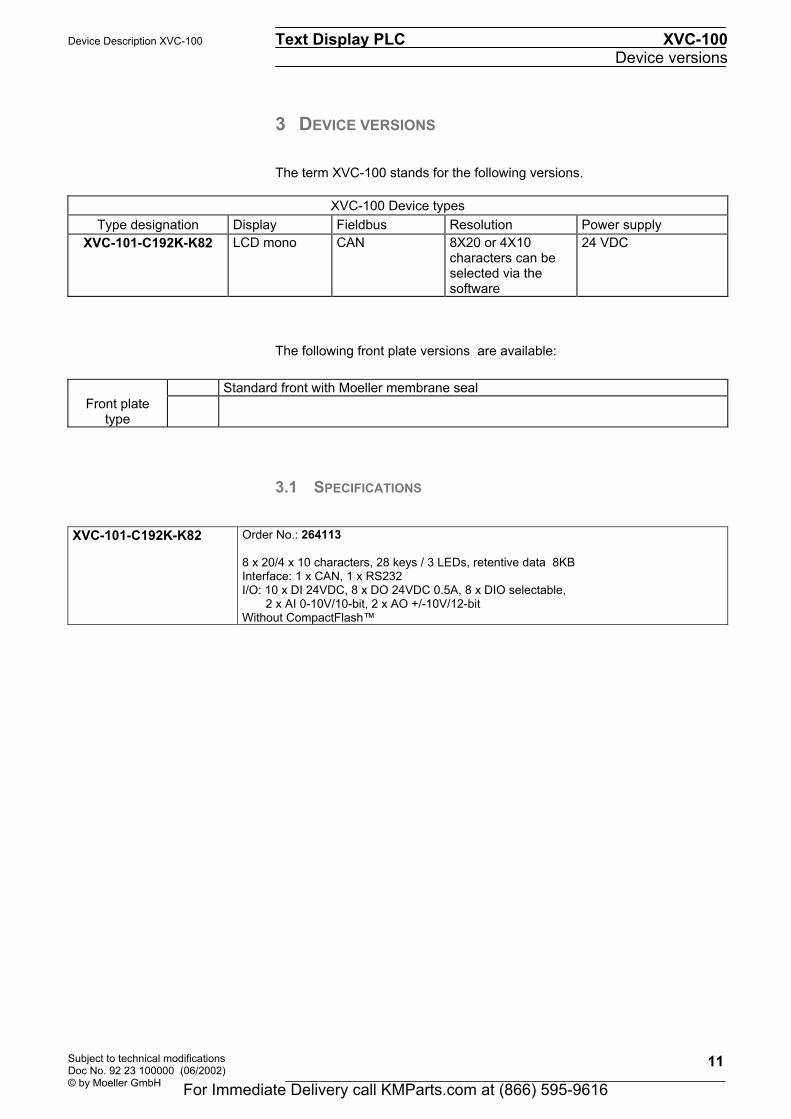
3 DEVICE VERSIONS The term XVC-100 stands for the following versions.
XVC-100 Device types Type designation Display Fieldbus Resolution Power supply
XVC-101-C192K-K82 LCD mono CAN 8X20 or 4X10 characters can be selected via the software
24 VDC
The following front plate versions are available:
Standard front with Moeller membrane seal Front plate
type
3.1 SPECIFICATIONS
XVC-101-C192K-K82
Order No.: 264113 8 x 20/4 x 10 characters, 28 keys / 3 LEDs, retentive data 8KB Interface: 1 x CAN, 1 x RS232 I/O: 10 x DI 24VDC, 8 x DO 24VDC 0.5A, 8 x DIO selectable, 2 x AI 0-10V/10-bit, 2 x AO +/-10V/12-bit Without CompactFlash
For Immediate Delivery call KMParts.com at (866) 595-9616

XVC-100 Text Display PLC Device Description XVC-100 Device versions
Subject to technical modifications Doc No. 92 23 100000 (06/2002)
© by Moeller GmbH
12
3.2 ACCESSORIES
CompactFlash
XT-MEM-CF8M Order No.: 264182 CompactFlash 8MB XT-MEM-CF16M1 Order No.: 256213 CompactFlash 16MB
Battery XT-CPU-BAT2 Order No.: 264115 Battery Spare battery (Type " Section11)
Programming cable XT-SUB-D-SUB-D Order No.: 264114 Programming cabel Programming cable RS232 Null modem (serial connection)
3.3 DESIGNING XSoft-Professional (on CD)
XSoftProfessional Consisting of: - XSoft -> IEC61131 software - Documentation in PDF format
For Immediate Delivery call KMParts.com at (866) 595-9616

Device Description XVC-100 Text Display PLC XVC-100 Features
Subject to technical modifications Doc No. 92 23 100000 (06/2002) © by Moeller GmbH
13
4 FEATURES
Feature Comment Display LCD text Resolution 8 x 20 or 4 x 10 characters can be selected via the
software Line height mm 4 or 8 Type Mono Keys Total Number 28 Function keys Number 8 PLC Languages IEC61131 IL, LD, FBD, SFC, ST, CFC PLC program KByte Configurable: Default: 384
(program + data max. 440) PLC data KByte Configurable: Default: 56
(program + data max. 440) Retentive data KByte Max. 8 Multi-tasking No Debug options Yes Online change, breakpoint, trace, flow control Cycle time/1000
instructions ms Normally 1 ms (Bit, Byte, Word, DWord
Operations) Digital Inputs of which Number 10 x 24VDC Counter inputs Number Configurable: Max. 2 x Up/Down Max. 50 kHz Interrupt inputs Number Configurable: Max. 2 Encoder inputs Number Configurable: 1 max. 50 kHz Digital outputs Number 8 x 24VDC 0.5A Digital inputs/outputs Number 8 x 24VDC 0.5A, individually configurable Analog inputs Number 2 x 0-10V/10-bit Analog outputs Number 2 x +/-10V/12-bit Real-time clock Yes Battery-backed Visualization User memory for
visualization KByte Max. 60 KByte text, parameters and recipes
Fonts Number 1 x large/small characters, variable, fixed1 Variable font Number 1 x large/small can be loaded Online languages Number Normally 5 Character languages Yes In preparation Text lines Number Max. 2200 at 20 characters each Operator function Yes Alphanumeric setpoint entry Signalling function Yes Display of process values, message texts,
time/date Recipes Yes Predefined parameters or loadable from
CompactFlash, configurable in PLC Password Yes Configurable in PLC Alarm Yes Configurable in PLC Communication COM1 (RS232) kBit/s Max. 57.6 CAN (CANopen) kBit/s CAN master, Max. 1000 Default: 125 Remote maintenance Yes Serial, with external modem Exchangeable memory
CompactFlash MByte 8 or 16MB
Software update via CompactFlash
Yes PLC project, visualization texts automatically on Power On; firmware update via System menu
The number of designable screen pages, messages, languages etc. is restricted by the memory available for visualization. The memory required per screen page greatly depends on the application concerned, and is mainly determined by the number and length of the texts shown. (60 KByte can store max. 55 pictures * 8 lines * 20 characters * 5 languages)
1 Standard font see Appendix
For Immediate Delivery call KMParts.com at (866) 595-9616

XVC-100 Text Display PLC Device Description XVC-100 Features
Subject to technical modifications Doc No. 92 23 100000 (06/2002)
© by Moeller GmbH
14
The display is controlled in the background and takes up max. 7 % of the CPU capacity. A complete screen change takes approx. 150 ms.
CompactFlash memory media are NOT suitable for cyclical data logging due to the limited number of write cycles (normally 100,000).
4.1 UTILISATION OF THE CAN IDENTIFIER (CANOPEN) The utilisation of the CAN identifier is in compliance with the CANopen Standard with the following deviations:
1. Selectable CAN node numbers (Node ID) are 1 to 31 2. The following additional CAN node numbers (node IDs) are
reserved for networking the devices: • Own node number + 32 • Own node number + 64 • Own node number + 96
Utilisation of the CAN node numbers (Node ID):
10 9 8 7 6 5 4 3 2 1 0
Node ID (CiA)
Function code Node ID (XVC-100)
For Immediate Delivery call KMParts.com at (866) 595-9616

Device Description XVC-100 Text Display PLC XVC-100 Commissioning
Subject to technical modifications Doc No. 92 23 100000 (06/2002) © by Moeller GmbH
15
5 COMMISSIONING
5.1 OVERVIEW OF CONNECTIONS
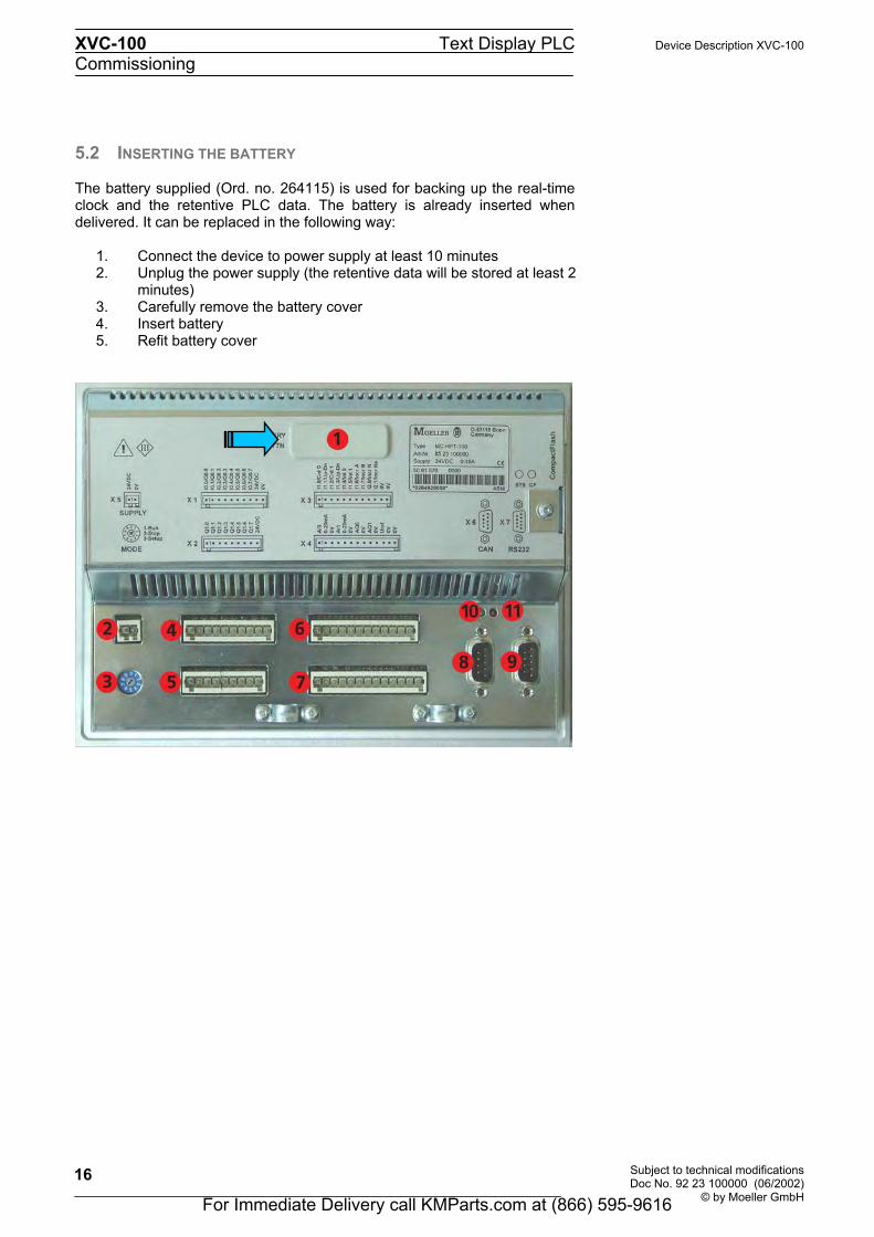
No. Element Description 1 Battery for retentive PLC data and real-time clock " Section 5.2 2 Connector X 5 (power supply) " Section 5.3 3 Operating mode switch " Section 6.4 4 Connector X 1 (Digital Input / Output) " Section 5.6 5 Connector X 2 (Digital Output) " Section 5.7 6 Connector X 3 (Digital Input) " Section 5.8 7 Connector X 4 (Analog Input / Output) " Section 5.9 8 Connector X 6 (CAN Communication Interface) " Section 5.10 9 Connector X 7 (RS232 Programming Interface) " Section 5.5 10 SYS control LED " Section 5.12 11 CompactFlash
control LED " Section 5.12
12-14 CompactFlash with protective cover and ejector " Section 5.11
For Immediate Delivery call KMParts.com at (866) 595-9616
XVC-100 Text Display PLC Device Description XVC-100 Commissioning
Subject to technical modifications Doc No. 92 23 100000 (06/2002)
© by Moeller GmbH
16
5.2 INSERTING THE BATTERY
The battery supplied (Ord. no. 264115) is used for backing up the real-time clock and the retentive PLC data. The battery is already inserted when delivered. It can be replaced in the following way:
1. Connect the device to power supply at least 10 minutes 2. Unplug the power supply (the retentive data will be stored at least 2 minutes) 3. Carefully remove the battery cover 4. Insert battery 5. Refit battery cover
For Immediate Delivery call KMParts.com at (866) 595-9616

Device Description XVC-100 Text Display PLC XVC-100 Commissioning
Subject to technical modifications Doc No. 92 23 100000 (06/2002) © by Moeller GmbH
17
5.3 CONNECTING THE POWER SUPPLY The XVC-100 device belongs to protection class 3. The system power supply must be provided with a 24VDC SELV voltage (" Section 11). The power supply is not isolated. The 0V connection is directly connected to the housing potential. The current supply is protected with a fuse (2A slow) (" Section 11). A reverse polarity protective device is used to protect the device in the event of reversed poles. Operation, however, is only possible if the connection was made correctly. Connections for the XVC-100 must comply with specific, local regulations. The connection must be made as follows:
• The cross-section of the power supply cable must be at least 0.75 mm² and a maximum of 2.5 mm².
• A flexible lead or wire can be used for the connection. • The current consumption (" Section 11 must be taken into account
when implementing the power supply. The functional earth is not compulsory for operation. The GND connection is directly connected to the housing potential
The plug connector for the connection is supplied with the unit. Connector assignment:
In the event of reverse polarity and if an additional 0 V connection is implemented, e.g. GND connection of an analog output, the fault current is fed via this 0V connection. The XVC-100 or the external components may be destroyed if the housing is not connected tightly to the 0V potential!
The XVC-100 text display PLC has a two-stage
undervoltage monitoring system. If level 1 is undershot, the backlight is switched off. If level 2 is undershot, the PLC is switched off.
X 5 - Supply 2-pole, WAGO multi-connector system
MINI, RM 3.5 mm, 734-132
Counterpart: WAGO 734-102 Pin No. Assignment Function
1 24VDC +24V power supply2 0V 0V power supply
24VDC 0V
21
For Immediate Delivery call KMParts.com at (866) 595-9616

XVC-100 Text Display PLC Device Description XVC-100 Commissioning
Subject to technical modifications Doc No. 92 23 100000 (06/2002)
© by Moeller GmbH
18
5.4 PREPARING THE SHIELD CONNECTIONS The preparation of the data and signal cables is an important factor for the electromagnetic compatibility (EMC) of the XVC-100, both in terms of interference immunity and emission. The RS232 interface and CAN interface are connected via D-Subminiature plug connectors in accordance with DIN 41652. Only use metal or metallized connector casings with a cable clamp for strain relief fastened or clamped on the connector. The clamping of the cable shield ensures an optimum contact area and a low impedance connection with the connector casing of the XVC-100 text display PLC. The following procedure is recommended for making the low-impedance connection for the cable shield:
1. Strip the cable. 2. Shorten the exposed shield braid by approx. 3 cm. 3. Turn back the braid over the cable sheath.
4. Use a heat shrinkable tubing or rubber grommet to cover the exposed cable sheath with the folded back shield braid so that 5 to 8 mm of exposed cable shield is left at the sheath end and is cleanly covered at the back.
5. Fit the connector
6. The cable is then fastened at the exposed shield braid and the cable sheath below it directly underneath the cable clamp strap of the connector casing.
Connection work should be carried out with special care in order to ensure trouble-free operation. The EMC values stated in the technical data can only be guaranteed if the cables are prepared according to the stated specifications.
Metal or metallised
D-subminiature connector
Metallicconnector shroud
Fasteningscrews
connector casing
Heat shrinkable tubing for covering the shield braid
Shield braid pulledback over the cable sheath
Strap for cable clampand contacting of the cable shield with theconnector casing
For Immediate Delivery call KMParts.com at (866) 595-9616

Device Description XVC-100 Text Display PLC XVC-100 Commissioning
Subject to technical modifications Doc No. 92 23 100000 (06/2002) © by Moeller GmbH
19
5.5 CONNECTING THE PROGRAMMING INTERFACE X7 The programming is carried out via the standard RS232 interface (COM1). The connection to the programming PC is made using a null modem cable. The cables are also available as an accessory (" Section 3.2). This interface is not isolated. The GND connection is implemented directly on the housing potential (" Section 11). Cables connected to the programming interface must be laid separately from the low-voltage cables. Connector assignment
Connector X 7 - RS232 programming interface Sub-D 9 Pole male
Pin No. Assignment Function 1 DCD Data Carry Detect 2 RXD Receive data 3 TXD Transmit Data 4 DTR Data Terminal Ready 5 GND Ground 6 DSR Ready for Operation 7 RTS Send Request 8 CTS Send Enable 9 RI Ring Indicator
Case Case Cable shield
A detailed description of the project download is provided in the XSoft system description or in the appropriate software documentation.
Wiring of the null modem cable
female female 9pole 25pole 25pole 9pole
DCD 1 8 20 4 DTR RXD 2 3 2 3 TD TXD 3 2 3 2 RD DTR 4 20 8/6 1/6 DCD/DSRGND 5 7 7 5 GND DSR 6 6 20 4 DTR RTS 7 4 5 8 CTS CTS 8 5 4 7 RTS RI 9 9
1 2 3 4 5
6 7 8 9
For Immediate Delivery call KMParts.com at (866) 595-9616
XVC-100 Text Display PLC Device Description XVC-100 Commissioning
Subject to technical modifications Doc No. 92 23 100000 (06/2002)
© by Moeller GmbH
20
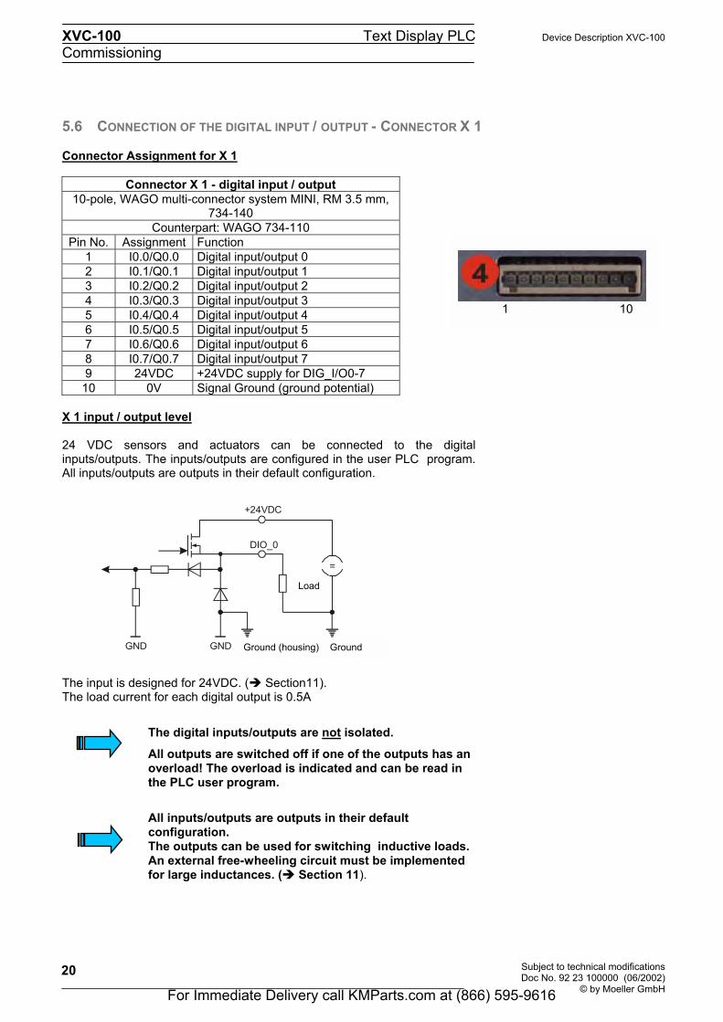
5.6 CONNECTION OF THE DIGITAL INPUT / OUTPUT - CONNECTOR X 1 Connector Assignment for X 1
Connector X 1 - digital input / output 10-pole, WAGO multi-connector system MINI, RM 3.5 mm,
734-140 Counterpart: WAGO 734-110
Pin No. Assignment Function 1 I0.0/Q0.0 Digital input/output 0 2 I0.1/Q0.1 Digital input/output 1 3 I0.2/Q0.2 Digital input/output 2 4 I0.3/Q0.3 Digital input/output 3 5 I0.4/Q0.4 Digital input/output 4 6 I0.5/Q0.5 Digital input/output 5 7 I0.6/Q0.6 Digital input/output 6 8 I0.7/Q0.7 Digital input/output 7 9 24VDC +24VDC supply for DIG_I/O0-7 10 0V Signal Ground (ground potential)
X 1 input / output level 24 VDC sensors and actuators can be connected to the digital inputs/outputs. The inputs/outputs are configured in the user PLC program. All inputs/outputs are outputs in their default configuration. The input is designed for 24VDC. (" Section11). The load current for each digital output is 0.5A The digital inputs/outputs are not isolated.
All outputs are switched off if one of the outputs has an overload! The overload is indicated and can be read in the PLC user program.
All inputs/outputs are outputs in their default configuration. The outputs can be used for switching inductive loads. An external free-wheeling circuit must be implemented for large inductances. (" Section 11).
+24VDC
DIO_0
Last
=
ErdeGNDGND Erde (Gehäuse)
1 10
Ground (housing) Ground
Load
For Immediate Delivery call KMParts.com at (866) 595-9616

Device Description XVC-100 Text Display PLC XVC-100 Commissioning
Subject to technical modifications Doc No. 92 23 100000 (06/2002) © by Moeller GmbH
21
5.7 CONNECTION OF THE DIGITAL OUTPUT - CONNECTOR X 2 Connector Assignment for X 2
Connector X 2 - digital output
9-pole, WAGO multi-connector system MINI, RM 3.5 mm, 734-139
Counterpart: WAGO 734-109 Pin No. Assignment Function
1 Q1.0 Digital output 0 2 Q1.1 Digital output 1 3 Q1.2 Digital output 2 4 Q1.3 Digital output 3 5 Q1.4 Digital output 4 6 Q1.5 Digital output 5 7 Q1.6 Digital output 6 8 Q1.7 Digital output 7 9 24VDC +24VDC supply for DIG_OUT0-7
X 2 output level Eight digital outputs are provided for 24VDC actuators. The power supply is fed via a separate pin and is common for all outputs. Each output is protected against short-circuits and reverse polarity. In the event of a fault, this is detected by the output driver. The load current for each digital output is 0.5A (" Section 11) The digital outputs are not isolated.
It must be ensured that there is a good connection between the reference potential (GND) for the digital outputs and the GND of the XVC-100.
All 8 outputs are switched off if one of the outputs has an overload! The overload is indicated and can be read in the PLC user program.
The outputs can be used for switching inductive loads. An external free-wheeling circuit must be implemented for large inductances. (" Section11).
Überwachung
+24VDC
DO_0
Last
=
ErdeGND Erde (Gehäuse)Ground (housing) Ground
Load
Monitoring
1 9
For Immediate Delivery call KMParts.com at (866) 595-9616

XVC-100 Text Display PLC Device Description XVC-100 Commissioning
Subject to technical modifications Doc No. 92 23 100000 (06/2002)
© by Moeller GmbH
22
5.8 CONNECTION OF THE DIGITAL INPUT - CONNECTOR X 3
Connector Assignment for X 3
Connector X 3 - digital input 12-pole, WAGO multi-connector system MINI, RM 3.5 mm,
734-142 Counterpart: WAGO 734-112
Pin No.
Assignment Function
1 I1.0/Cnt 0 Digital input 0 / Counter0 input 2 I1.1/Up-Dn Digital input 1 / Counter0 Up/Down 3 I1.2/Cnt 1 Digital input 2 / Counter1 input 4 I1.3/Up-Dn Digital input 3 / Counter1 Up/Down 5 I1.4/Int 0 Digital input 4 / Interrupt0 input 6 I1.5/Int 1 Digital input 5 / Interrupt1 input 7 I1.6/Incr A Digital input 6 / Incr. Ch A 8 I1.7/Incr B Digital input 7 / Incr. Ch B 9 I2.0/Incr N Digital input 8 / Incr. zero mark
10 I2.1/Incr Na Digital input 9 / Incr. zero mark active 11 0V Signal Ground (ground potential) 12 0V Signal Ground (ground potential)
X 3 input level
Function:Digital Inputs
Ten digital inputs are provided. These inputs enable 24 volt digital sensors, counters and incremental encoders to be connected. The input is designed for 24VDC. (" Section 11).
The digital inputs are not isolated, the input voltage refers toground (GND).
The debouncing of inputs is implemented via the software. This function must be activated if required. (see also Description of the function block libraries for XVC-100)
DIO_0
GND GND Ground (h i )
=
1 12
For Immediate Delivery call KMParts.com at (866) 595-9616

Device Description XVC-100 Text Display PLC XVC-100 Commissioning
Subject to technical modifications Doc No. 92 23 100000 (06/2002) © by Moeller GmbH
23
Function: Counter Inputs Two counter inputs are provided. These allow counter functions with a maximum input frequency of 50 kHz each. The switch thresholds are the same as the signal values of the digital inputs (" Section11). Function:Interrupt Inputs Two Interrupt inputs are provided. The switch thresholds are the same as the signal values of the digital inputs (" Section 11).
Function:Incremental Encoder Inputs An incremental encoder input is provided. The switch thresholds are the same as the signal values of the digital inputs (" Section 11 ).
The connected incremental encoder must be provided with a push-pull interface! Counters and incremental encoder inputs must be shielded.
For Immediate Delivery call KMParts.com at (866) 595-9616

XVC-100 Text Display PLC Device Description XVC-100 Commissioning
Subject to technical modifications Doc No. 92 23 100000 (06/2002)
© by Moeller GmbH
24
5.9 CONNECTION OF THE ANALOG INPUT / OUTPUT - CONNECTOR X 4 Connector Assignment for X 4
Connector X 4 - analog input / output 13-pole, WAGO multi-connector system MINI, RM 3.5 mm,
734-143 Counterpart: WAGO 734-113
Pin No. Assignment Function 1 AI0 Analog voltage input 0 2 0-20mA Analog current resistor 0 3 0V Signal GND 4 AI1 Analog voltage input 1 5 0-20mA Analog current resistor 0 6 0V Signal GND 7 AQ0 Analog voltage output 0 8 0V Signal GND 9 AQ1 Analog voltage output 0
10 0V Signal GND 11 Uref 4.096VDC reference output (1mA) 12 0V Signal Ground (ground potential) 13 0V Signal Ground (ground potential)
X 4 input / output level Function: Analog Input The analog inputs can be used for measuring and processing voltages and currents. The evaluation of the analog value is processed via the same terminal pin the voltage input is changed to a current input by connecting a parallel resistor. The diagram below shows the structure of the analog input. Voltage Input: The input range is 0 to +10VDC The input resistance is 1MΩ Current Input: The input range is 0 to +20mA The current measuring resistance R is 500Ω The A/D converter has a 10-bit resolution (LSB = 9.766mV)
The analog inputs are not isolated. The connections must be shielded. The shield connections must be grounded on the housing. Mean analog input values are automatically determined from the 8 most recent measured values. (arithmetic mean)
+ IA0_U
+ IA0_I
0V
= R
1 13
For Immediate Delivery call KMParts.com at (866) 595-9616
Device Description XVC-100 Text Display PLC XVC-100 Commissioning
Subject to technical modifications Doc No. 92 23 100000 (06/2002) © by Moeller GmbH
25
The analog inputs are single ended and do not allow differential measurements. If a potentiometer is used as a reference value potentiometer, the voltage must be well decoupled and the GND well connected.
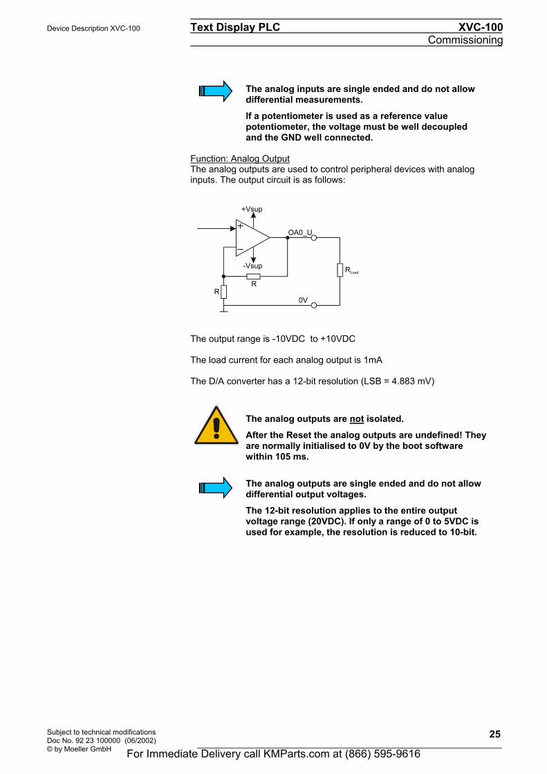
Function: Analog Output The analog outputs are used to control peripheral devices with analog inputs. The output circuit is as follows:
The output range is -10VDC to +10VDC The load current for each analog output is 1mA The D/A converter has a 12-bit resolution (LSB = 4.883 mV)
The analog outputs are not isolated. After the Reset the analog outputs are undefined! They are normally initialised to 0V by the boot software within 105 ms.
The analog outputs are single ended and do not allow differential output voltages. The 12-bit resolution applies to the entire output voltage range (20VDC). If only a range of 0 to 5VDC is used for example, the resolution is reduced to 10-bit.
0V
RR
+Vsup
-Vsup
OA0_U
RLoad
For Immediate Delivery call KMParts.com at (866) 595-9616

XVC-100 Text Display PLC Device Description XVC-100 Commissioning
Subject to technical modifications Doc No. 92 23 100000 (06/2002)
© by Moeller GmbH
26
5.10 CONNECTION OF THE CAN INTERFACE - CONNECTOR X 6
The communication interface is defined in accordance with the CiA CAN Specification V2.0 part B. The fully-integrated CAN unit supports the sending and receiving of frames with an 11-bit Identifier. The type of configuration selected depends on the software protocol. The baud rate can be selected in a wide range, and only the standard CiA baud rates are implemented. The XVC-100 is the master on the CAN bus.
CAN connector X 6 Sub-D 9 Pole male
Connector
Pin No. Assignment Function
1 - 2 CAN LOW Negative data signal 3 GND Signal Ground (ground potential) 4 - 5 - 6 GND Signal Ground (ground potential) 7 CAN HIGH Positive data signal 8 - 9 - Case Case Cable shield
The CAN interface is not isolated.
The terminating resistor must be implemented externally, e.g. in the connector, and is not part of the device. The CAN connector is not provided with a supply for third-party devices. A detailed description of the wiring is provided in the XSoft system description
59
48
37
26
1
For Immediate Delivery call KMParts.com at (866) 595-9616

Device Description XVC-100 Text Display PLC XVC-100 Commissioning
Subject to technical modifications Doc No. 92 23 100000 (06/2002) © by Moeller GmbH
27
Wiring instructions The stations on the bus system are connected via fieldbus lines complying with ISO 11898. The cables must accordingly have the following electrical characteristics: Parameter Abbreviation Unit Value Value Value Note min. nom. max. Impedance Z Ω 108 120 132 Measured between two
signal lines Specific resistance
mΩ/m 70 For the receiver module, the differential voltage on the bus cable depends on cable resistance between it and the sender
Cable delay ns/m 5 The mininum delay between to points on the bus is 0. The maximum delay is determined by the bit timing and the delays of the sender and receiver circuits
The figure shows the minimum wiring with shielding between two bus stations with the Sub-D connector as an example. A bus terminating resistor (120 Ohm between Pin 2 and Pin 7 of the Sub-D connector) must be connected at the beginning and the end of each CAN bus. Do not swap around the two signal wires!
Protective ground
Shield
Interface 1 Interface 2
Protective ground
For Immediate Delivery call KMParts.com at (866) 595-9616

XVC-100 Text Display PLC Device Description XVC-100 Commissioning
Subject to technical modifications Doc No. 92 23 100000 (06/2002)
© by Moeller GmbH
28
Pin 3 and 6 (CAN_GND) are both connected internally with the CAN Ground. Pins 4, 5 and 8 must not be connected! The CAN bus driver is fed internally.
Baud rate and cable lengths Baud rate Max. length 20kBit/sec 2500m 25kBit/sec 2000m 50kBit/sec 1000m 100kBit/sec 650m 125kBit/sec 500m 250kBit/sec 250m 500kBit/sec 100m 800kBit/sec 20m 1000kBit/sec 6m
Shield Inside: twisted pair cable
Station 1 Station n
bus terminating resistor
For Immediate Delivery call KMParts.com at (866) 595-9616

Device Description XVC-100 Text Display PLC XVC-100 Commissioning
Subject to technical modifications Doc No. 92 23 100000 (06/2002) © by Moeller GmbH
29
5.11 INSERTING THE COMPACTFLASH The XVC-100 series devices can use a CompactFlash for optional data storage (e.g. recipes). The runtime system and the application are stored on the Flash inside the device. To do this undo the cover of the CompactFlash Interface and fit a suitable CompactFlash from the original accessories. The cover must be refitted and fastened.
The CompactFlash must only be inserted / removed when the red LED is not lit! This may otherwise lead to loss of data.
Apart from the above restriction, the CompactFlash can be inserted or removed when the power supply has been switched on. Correct functioning can only be ensured by using CompactFlash cards obtained from the original accessories.
CompactFlash control LED (red)
For Immediate Delivery call KMParts.com at (866) 595-9616

XVC-100 Text Display PLC Device Description XVC-100 Commissioning
Subject to technical modifications Doc No. 92 23 100000 (06/2002)
© by Moeller GmbH
30
5.12 FUNCTION AND CONTROL LEDS
Control LED on rear The red CompactFlash LED indicates that the XVC-100 text display PLC is accessing the CompactFlash. The CompactFlash cannot be inserted / removed as long as this LED is lit. The green SYS control LED has the following function:
• Flashes at approx. 1 Hz # System menu active
CompactFlash control LED (red) SYS control LED (green)
For Immediate Delivery call KMParts.com at (866) 595-9616

Device Description XVC-100 Text Display PLC XVC-100 Commissioning
Subject to technical modifications Doc No. 92 23 100000 (06/2002) © by Moeller GmbH
31
5.13 MEMBRANE KEYBOARD
The membrane keyboard has 28 keys, of which 8 are function keys. The keys are evaluated in the PLC user program by means of appropriate function blocks. (see also Description of the function block libraries for XVC-100)
For Immediate Delivery call KMParts.com at (866) 595-9616

XVC-100 Text Display PLC Device Description XVC-100 Commissioning
Subject to technical modifications Doc No. 92 23 100000 (06/2002)
© by Moeller GmbH
32
For Immediate Delivery call KMParts.com at (866) 595-9616
Device Description XVC-100 Text Display PLC XVC-100 Operation
Subject to technical modifications Doc No. 92 23 100000 (06/2002) © by Moeller GmbH
33
6 OPERATION
6.1 STARTUP BEHAVIOUR After power on, the XVC-100 carries out a system test. The PLC does not switch to Run or Stop until no hardware errors have been found. The system test includes the following:
• LED test (all LEDs are activated momentarily on power on) • Memory test • User program test
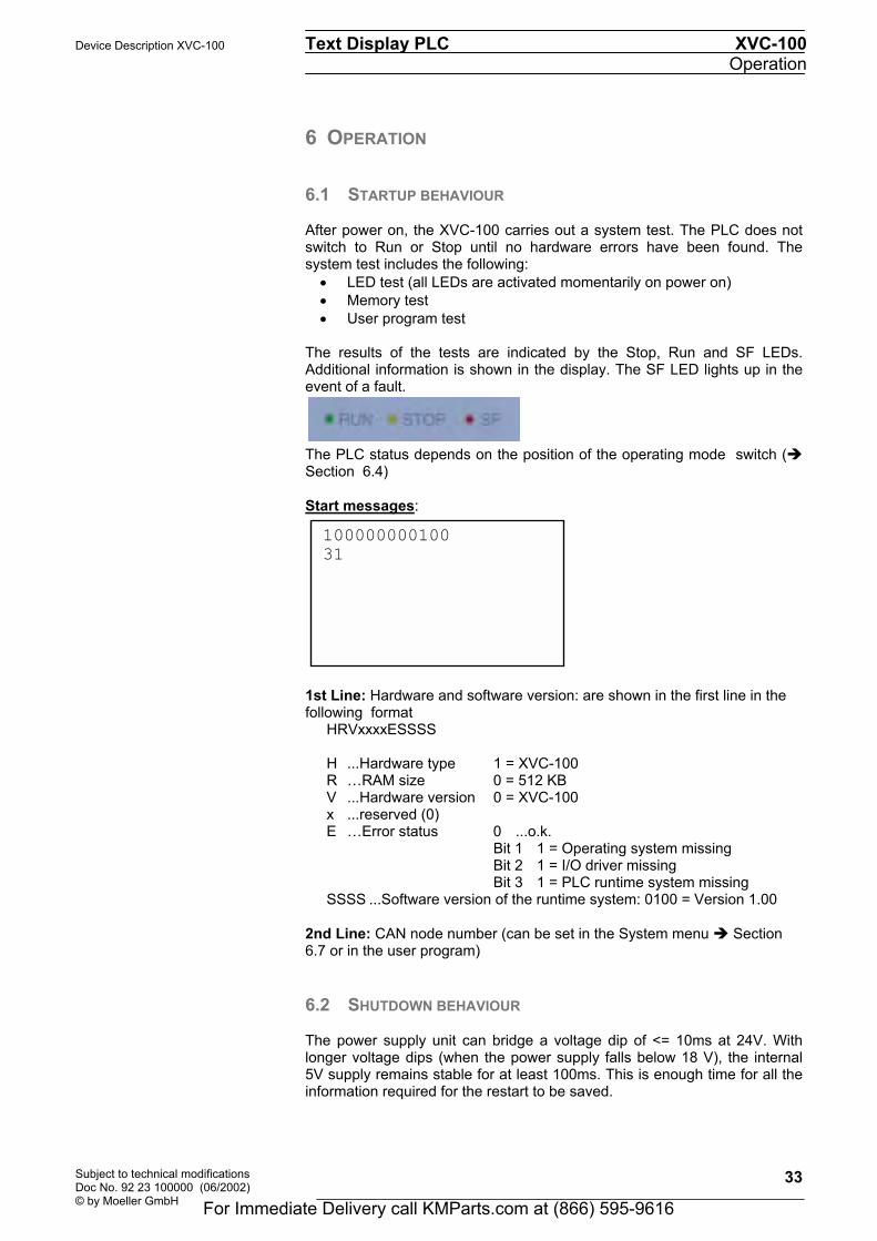
The results of the tests are indicated by the Stop, Run and SF LEDs. Additional information is shown in the display. The SF LED lights up in the event of a fault. The PLC status depends on the position of the operating mode switch (" Section 6.4) Start messages: 1st Line: Hardware and software version: are shown in the first line in the following format
HRVxxxxESSSS H ...Hardware type 1 = XVC-100 R RAM size 0 = 512 KB V ...Hardware version 0 = XVC-100 x ...reserved (0) E Error status 0 ...o.k. Bit 1 1 = Operating system missing
Bit 2 1 = I/O driver missing Bit 3 1 = PLC runtime system missing
SSSS ...Software version of the runtime system: 0100 = Version 1.00 2nd Line: CAN node number (can be set in the System menu " Section 6.7 or in the user program)
6.2 SHUTDOWN BEHAVIOUR
The power supply unit can bridge a voltage dip of <= 10ms at 24V. With longer voltage dips (when the power supply falls below 18 V), the internal 5V supply remains stable for at least 100ms. This is enough time for all the information required for the restart to be saved.
100000000100 31
For Immediate Delivery call KMParts.com at (866) 595-9616

XVC-100 Text Display PLC Device Description XVC-100 Operation
Subject to technical modifications Doc No. 92 23 100000 (06/2002)
© by Moeller GmbH
34
6.3 PLC OPERATING STATES Power on Power on status is indicated by a flashing Stop LED: In Power on status, there is no user program in the PLC. Stop The Stop operating status has the following features:
• A user program is stored on the PLC. • The user program is not running
The Stop status is selected:
• After the power supply has been switched on when the operating mode switch has been switched to Stop position.
• Via the programming software in the PC • After a cycle time violation (this causes the PLC to restart in Stop
mode) Run In RUN status, the user program is processed cyclically. The RUN operating status is selected:
• After the power supply has been switched on when the operating mode switch has been switched to Run position.
• Via the programming software in the PC System Fault SF The SF LED indicates a system fault. The following system faults can occur (" Section 9):
• Hardware fault • System fault in firmware
For Immediate Delivery call KMParts.com at (866) 595-9616
Device Description XVC-100 Text Display PLC XVC-100 Operation
Subject to technical modifications Doc No. 92 23 100000 (06/2002) © by Moeller GmbH
35
6.4 CHANGING OPERATING MODE
With XVC-100 devices, the operating mode switch or the programming software are used to change the operating mode. Operating mode switch (OMS): The operating mode switch on the rear of the device is assigned the following modes: (" Section 6.3)
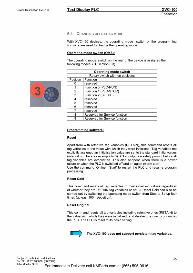
Operating mode switch
Rotary switch with ten positions Position Function
0 reserved 1 Function 0 (PLC-RUN) 2 Function 1 (PLC-STOP) 3 Function 2 (SETUP) 4 reserved 5 reserved 6 reserved 7 reserved 8 Reserved for Service function 9 Reserved for Service function
Programming software:
Reset Apart from with retentive tag variables (RETAIN), this command resets all tag variables to the value with which they were initialised. Tag variables not explicitly assigned an initialisation value are set to the standard initial values (integral numbers for example to 0). XSoft outputs a safety prompt before all tag variables are overwritten. This also happens when there is a power failure or when the PLC is switched off and on again (warm start). Use the command Online, Start to restart the PLC and resume program processing. Reset Cold This command resets all tag variables to their initialised values regardless of whether they are RETAIN tag variables or not. A Reset Cold can also be carried out by switching the operating mode switch from Stop to Setup four times (at least 100ms/position). Reset Original This command resets all tag variables including retentive ones (RETAIN) to the value with which they were initialised, and deletes the user program on the PLC. The PLC is reset to its basic setting.
The XVC-100 does not support persistent tag variables.
For Immediate Delivery call KMParts.com at (866) 595-9616

XVC-100 Text Display PLC Device Description XVC-100 Operation
Subject to technical modifications Doc No. 92 23 100000 (06/2002)
© by Moeller GmbH
36
Start The command starts the running of the user program in the PLC. The command can be executed directly after the commands Online, Load or after the user program was stopped in the PC via the commands Online, Stop, or if the user program is at a break point, or after the commands 'Online', 'Single Cycle'. A detailed description of the online functions is also provided the XSoft manual.
6.5 STARTUP BEHAVIOUR/STARTUP After the power supply is switched on, the user program is loaded from the internal flash memory into the RAM, and the PLC is started. Procedure:
Power on
PLC-Programm
present ?
RetainDatao.k. ? Reset-cold
Start (OMS)
PLC-Status:Run
PLC-Status:Stop
PLC-Status:System Fault
PLC-Status:Power on
OMS=RUN?
OMS=STOP?
Hardware-o.k.?
No
No
No
No
For Immediate Delivery call KMParts.com at (866) 595-9616

Device Description XVC-100 Text Display PLC XVC-100 Operation
Subject to technical modifications Doc No. 92 23 100000 (06/2002) © by Moeller GmbH
37
6.6 PROGRAM TRANSFER If the user program was compiled error-free on the programming device (PC), it can be loaded into the working memory of the XVC-100 and then started. PC # PLC: During a program transfer from the PC to the PLC, the program in the PLC is compared with the program in the PC. If they are not the same, a prompt will ask whether the program is to be overwritten. If this prompt is confirmed, the PLC switches to Stop status and the new program is loaded into the working memory. The position of the operating mode switch is not important for this (for program transfer see also XSoft manual). The user program is stored in the internal flash memory by generating a boot project. PC # PLC and CompactFlash: A program transfer from the PC to the CompactFlash in the PLC is in preparation. (see notes on Firmware)
For Immediate Delivery call KMParts.com at (866) 595-9616

XVC-100 Text Display PLC Device Description XVC-100 Operation
Subject to technical modifications Doc No. 92 23 100000 (06/2002)
© by Moeller GmbH
38
6.7 SYSTEM SETTINGS XVC-100 devices allow the following system settings via the System menu:
• Setting of the CAN parameters Node number from 1 to 31 (Default:
31, " Section4.1) and baud rate (Default: 125kBit/s)
• Setting of the serial interface (Default: 57,6 KByte 8, n, 1)
• Contrast setting
• Firmware update
The System menu can be called in the following way:
• The System menu is called automatically when there are hardware faults or when system software components (e.g. runtime system) are missing
• With the device switched off set the operating mode switch to Position 3 (Setup). Then switch on the device.
Main menu The System menu will show the following screen once it has been started: 00000000 " Hardware Type (" Section 6.1) BSW XX.YY " Boot software version
• You can use the (Up /Down arrows) keys to set the contrast. • Press the ENTER key to save the settings (contrast, CAN, RS232)
in the flash memory. The saved settings are accepted by the runtime system during startup. To start the runtime system, set the operating mode switch to Position 1 (RUN) or 2 (STOP) and press the ENTER key.
• Fault messages are displayed instead of BSW XX.YY (" Section 9)
00000000 BSW XX.YY -> Contrast +/- F1 -> CAN Setup F2 -> RS232 Setup F3 -> SW update ENTER-> Save/Restart
For Immediate Delivery call KMParts.com at (866) 595-9616

Device Description XVC-100 Text Display PLC XVC-100 Operation
Subject to technical modifications Doc No. 92 23 100000 (06/2002) © by Moeller GmbH
39
CAN settings Press the F1 key to enter the CAN Setup menu for accessing the CAN settings. When a setting is changed, the CAN bus will be reconfigured straightaway according to the new setting. The settings can only be saved from the main menu.
• Use the keys to move between CAN Id and CAN Baud rate. • Use the keys to change the selected setting. • Use ENTER to exit the CAN Settings menu without saving
RS232 settings Pressing the F2 key calls up the RS232 Setup menu for accessing the RS232 settings. When a setting is changed, the serial interface will be reconfigured straightaway according to the new setting. The settings can only be saved from the main menu.
• Use the keys to change the Baud rate • Press ENTER to exit the RS232 Settings menu without saving
00000000 BSW XX.YY ->CAN Id : 31 <- Baud rate: 125K -> Choose -> Modify ENTER-> Back
00000000 BSW XX.YY ->Baud rate: 57.6K<- -> Modify ENTER-> Back
For Immediate Delivery call KMParts.com at (866) 595-9616

XVC-100 Text Display PLC Device Description XVC-100 Operation
Subject to technical modifications Doc No. 92 23 100000 (06/2002)
© by Moeller GmbH
40
Firmware update This System menu enables you to make firmware updates via CAN, RS232 and CompactFlash. In order to carry out updates via CAN or RS232, you need the GatewayMonitor program (see also the XSoft system description). Updates via CompactFlash can be carried out directly. To do this press key F3. This will open the following display:
• Pressing the ESC key aborts the operation The CompactFlash for a firmware update can be created using the SetupTargetFirmware.exe program from the XSoft CD. Then insert the CompactFlash. The existing software is checked and the software versions displayed:
•
• Pressing the ESC key aborts the operation • Pressing the ENTER key starts the update.
The CompactFlash must be removed once the update has been completed. The device is then restarted.
This operation must be repeated if the firmware update is not carried out completely (e.g. power failure). The saved PLC project is retained during a firmware update.
00000000 BSW XX.YY Please insert CF.... ESC-> Abort
00000000 BSW XX.YY Replace SW xx.xx By SW yy.yy ESC -> Abort ENTER-> YES, replace
For Immediate Delivery call KMParts.com at (866) 595-9616
Device Description XVC-100 Text Display PLC XVC-100 Mounting instructions
Subject to technical modifications Doc No. 92 23 100000 (06/2002) © by Moeller GmbH
41
7 MOUNTING INSTRUCTIONS
7.1 GENERAL MOUNTING INSTRUCTIONS All XVC-100 Series devices are mounted from the front, i.e. in a control panel. The devices are fastened from the rear with the fixing clamps supplied. All XVC-100 Series devices can be operated at an ambient temperature of up to 60°C (" Section 11 ). The ambient temperature stated applies to the area in the direct vicinity of the lower connectors if the device is mounted vertically with unimpeded air convection and a maximum operating height of 2000m above sea level. The device can be mounted in an enclosure if the permissible ambient temperature is observed. Provide a wall clearance of at least 50 mm on all sides of the housing, so that sufficient air circulation is ensured. A minimum clearance of 75 mm from active elements such as load current supply, transformers etc. must be ensured. Avoid the exposure of the membrane keyboard and display to direct sunlight. The radiation from the sun (UV component) reduces the lifespan of the LCD display.
The following must be ensured in order to prevent the device from overheating during operation:
- The cooling slots must always be free in order to ensure the proper cooling of the system.
- Avoid the exposure of the front and the display to direct sunlight.
- The mounting angle must not exceed ± 35° from the vertical
Mounting in compliance with degree of protection IP65 requires the use of the conter frame . Ensure that the seal is fitted correctly on the front panel.
For Immediate Delivery call KMParts.com at (866) 595-9616

XVC-100 Text Display PLC Device Description XVC-100 Mounting instructions
Subject to technical modifications Doc No. 92 23 100000 (06/2002)
© by Moeller GmbH
42
7.2 MOUNTING IN THE FRONT PANEL 1. Push the XVC-100 from the front into the cutout (" Section 7.3) of the
front panel. 2. The front seal must be level and evenly positioned between the front
plate and the front panel. 3. Secure the device with the 4 fixing clamps supplied and tighten evenly
from the rear until the front plate is flush with the front panel.
Ensure that the seal is fitted correctly on the front panel.Avoid tightening torques of greater than 0.3 Nm as this could otherwise damage the device. The maximum thickness of the front panel should not exceed 5 mm. The conter frame can be used for mounting in thin-walled front panels <= 2 mm.
max. 5
For Immediate Delivery call KMParts.com at (866) 595-9616

Device Description XVC-100 Text Display PLC XVC-100 Mounting instructions
Subject to technical modifications Doc No. 92 23 100000 (06/2002) © by Moeller GmbH
43
7.3 FRONT CUTOUT
The device requires a mounting cutout of WxH: 198 +0/-1 mm x 142 +0/-1 mm
The thickness of the front panel must not exceed 5 mm.
For Immediate Delivery call KMParts.com at (866) 595-9616

XVC-100 Text Display PLC Device Description XVC-100 Mounting instructions
Subject to technical modifications Doc No. 92 23 100000 (06/2002)
© by Moeller GmbH
44
7.4 MECHANICAL DIMENSIONS
50 5
For Immediate Delivery call KMParts.com at (866) 595-9616
Device Description XVC-100 Text Display PLC XVC-100 Display, backlight, contrast
Subject to technical modifications Doc No. 92 23 100000 (06/2002) © by Moeller GmbH
45
8 DISPLAY, BACKLIGHT, CONTRAST
8.1 CONTRAST The contrast voltage can be set in the System menu (" Section 6.7).
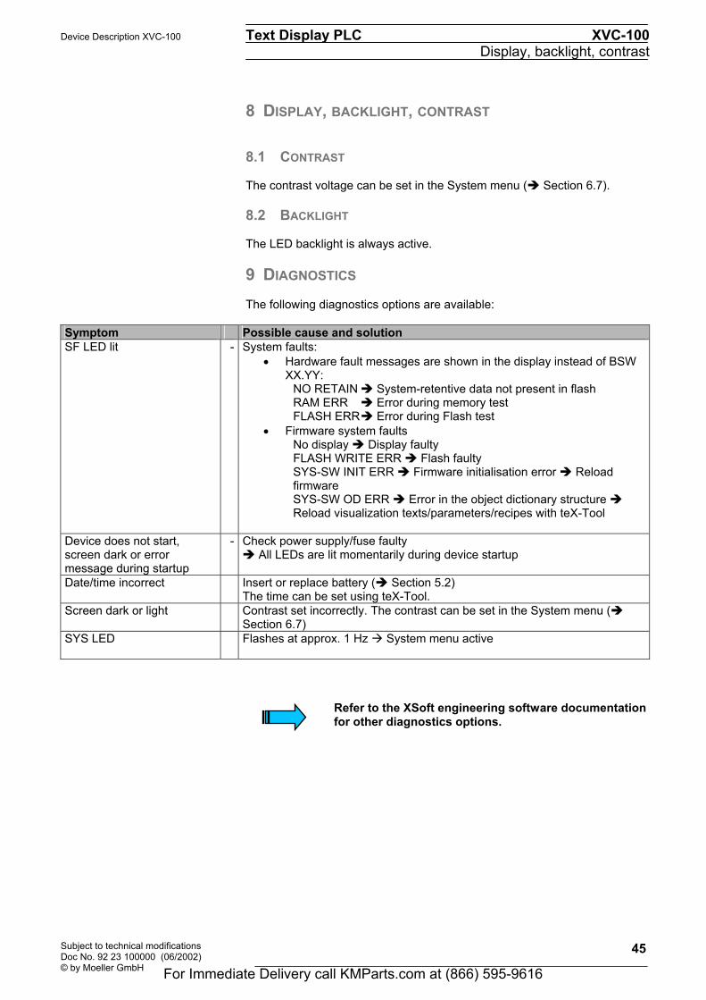
8.2 BACKLIGHT The LED backlight is always active. 9 DIAGNOSTICS The following diagnostics options are available:
Symptom Possible cause and solution SF LED lit - System faults:
• Hardware fault messages are shown in the display instead of BSW XX.YY: NO RETAIN " System-retentive data not present in flash RAM ERR " Error during memory test FLASH ERR " Error during Flash test
• Firmware system faults No display " Display faulty FLASH WRITE ERR " Flash faulty SYS-SW INIT ERR " Firmware initialisation error " Reload firmware SYS-SW OD ERR " Error in the object dictionary structure " Reload visualization texts/parameters/recipes with teX-Tool
Device does not start, screen dark or error message during startup
- Check power supply/fuse faulty " All LEDs are lit momentarily during device startup
Date/time incorrect Insert or replace battery (" Section 5.2) The time can be set using teX-Tool.
Screen dark or light Contrast set incorrectly. The contrast can be set in the System menu (" Section 6.7)
SYS LED Flashes at approx. 1 Hz # System menu active
Refer to the XSoft engineering software documentation for other diagnostics options.
For Immediate Delivery call KMParts.com at (866) 595-9616

XVC-100 Text Display PLC Device Description XVC-100 Display, backlight, contrast
Subject to technical modifications Doc No. 92 23 100000 (06/2002)
© by Moeller GmbH
46
For Immediate Delivery call KMParts.com at (866) 595-9616
Device Description XVC-100 Text Display PLC XVC-100 Maintenance and repair
Subject to technical modifications Doc No. 92 23 100000 (06/2002) © by Moeller GmbH
47
10 MAINTENANCE AND REPAIR Battery The battery is used for backing up the real-time clock and the retentive PLC data. The battery should be changed every 3 years in order to prevent any data loss. Procedure for changing the battery 1. Switch on the device for at least 10 minutes
2. Then switch off the device and change the battery quickly
(the data is retained without a battery for approx. 2 minutes)
Repairs Repairs to the XVC-100 should only be carried out by the manufacturer or by Moeller GmbH repair centers. In this case, please contact your local XSystem dealer or the Technical Support at Moeller GmbH. (manufacturer's address " Section 13) No liability is accepted for any modifications made to the device that are not described in this document. Transport Only the original packaging must be used for transporting the device.
For Immediate Delivery call KMParts.com at (866) 595-9616

XVC-100 Text Display PLC Device Description XVC-100 Maintenance and repair
Subject to technical modifications Doc No. 92 23 100000 (06/2002)
© by Moeller GmbH
48
For Immediate Delivery call KMParts.com at (866) 595-9616

Device Description XVC-100 Text Display PLC XVC-100 Technical data
Subject to technical modifications Doc No. 92 23 100000 (06/2002) © by Moeller GmbH
49
11 TECHNICAL DATA
Display Technology Passive matrix mono LC display (Mono STN-LCD yellow-green )
Resolution 128 x 64 pixels Display area 71 mm x 39 mm Backlight LED Operation Membrane keyboard 28 keys; 3 LEDs Ambient conditions
Operating climate 0...60°C, 10...90% rel. air humidity, non-condensing
Storage climate -25...85°C, 10...90% rel. air humidity, non-condensing EMC interference immunity EN 61000-6-2 Emission EN 50081-2 Degree of protection
Front IP 65 (NEMA 12), to EN 60529 IP65 protection only with additional mounting kit! (" Section 7)
Rear IP 20 Weight Approx. 0.9 kg Dimensions W x H x D 212 x 156 x 50 mm Cutout 198 x 142 mm (+0/-1mm) System supply Rated voltage 24 VDC SELV, safety extra low voltage Voltage range 24 VDC to DIN 19240
20.4...28.8 VDC effective, absolute value with ripple 18.5...30.2 VDC 35.0 VDC for a duration of < 100ms
Voltage dips 100 ms max., at 20.4 VDC to 0 VDC, repetition rate 1 s Protection against reverse
polarity Yes (" Section 5.3)
Fuse protection Yes Potential isolation No
The 0V connection is directly connected to the housing potential (GND) Current consumption Normally 160mA/24VDC Power consumption Normally 4 W/24VDC Battery backup Battery type 3V / 950mAh Lithium, RENATA CR2477N Data retention Normally 5 years Real-time clock Counters Seconds, minutes, hour, day, month, year, decade Leap year change Automatic DST change Via the software Deviation at Tamb=25°C Normally +/- 100ppm Fuse Inside the unit 2 A slow
(not accessible from outside," Section 5.3) Breaking capacity Max. 30A Programming interface
Type RS 232, not potential-free (" Section 5.5)
Connection Sub-D pole male Communication interface
Type CAN, not potential-free (" Section 5.10)
Connection D-Subminiature 9-pole male
For Immediate Delivery call KMParts.com at (866) 595-9616

XVC-100 Text Display PLC Device Description XVC-100 Technical data
Subject to technical modifications Doc No. 92 23 100000 (06/2002)
© by Moeller GmbH
50
CompactFlash slot
CompactFlash Type 1
Technology ATA Flash, 5V Connector X 1 Type Digital inputs/outputs Number of I/O 8 Number of supply terminals 1 Number of 0V terminals 1 Supply voltage for outputs Normally 24VDC (18.5VDC...30.2VDC) Max. output current per channel 0.5 A Inductive loads Max. 150mJ Input voltage Low
High -3...4.5VDC 14...32.0VDC
Input current Low High
0..1mA 2..15mA
Max. input voltage 40VDC Protection against reverse
polarity Yes
Potential isolation No Protected against short-circuit Yes Supply monitoring Yes Fault status Common for all outputs Connector X 2 Type Digital outputs Number of I/O 8 Number of supply terminals 1 Supply voltage Normally 24VDC (18.5VDC...30.2VDC) Max. output current per channel 0.5 A Inductive loads Max. 150mJ Protection against reverse
polarity Yes
Potential isolation No Protected against short-circuit Yes Supply monitoring Yes Fault status Common for all outputs Connector X 3 Type Digital inputs Function: Digital Input
Number 10, all of which have a second function (" Section 5.8)
Number of 0V terminals 1 Input voltage Low
High -3...4.5VDC 14...32.0VDC
Input current Low High
0..1mA 2..15mA
Max. input voltage 40VDC Protection against reverse
polarity Yes
Potential isolation No Function Counter Input
Number 2
Input voltage Low High
-3...4.5VDC 14...32.0VDC
Input current Low High
0..1mA 2..15mA
Max. input voltage 40VDC Protection against reverse
polarity Yes
For Immediate Delivery call KMParts.com at (866) 595-9616
Device Description XVC-100 Text Display PLC XVC-100 Technical data
Subject to technical modifications Doc No. 92 23 100000 (06/2002) © by Moeller GmbH
51
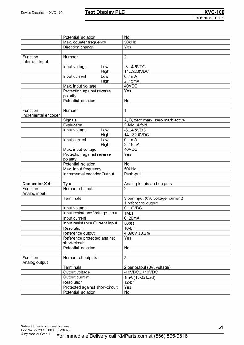
Potential isolation No Max. counter frequency 50kHz Direction change Yes Function Interrupt Input
Number 2
Input voltage Low High
-3...4.5VDC 14...32.0VDC
Input current Low High
0..1mA 2..15mA
Max. input voltage 40VDC Protection against reverse
polarity Yes
Potential isolation No Function Incremental encoder
Number 1
Signals A, B, zero mark, zero mark active Evaluation 2-fold, 4-fold Input voltage Low
High -3...4.5VDC 14...32.0VDC
Input current Low High
0..1mA 2..15mA
Max. input voltage 40VDC Protection against reverse
polarity Yes
Potential isolation No Max. input frequency 50kHz Incremental encoder Output Push-pull Connector X 4 Type Analog inputs and outputs Function: Analog input
Number of inputs 2
Terminals 3 per input (0V, voltage, current) 1 reference output
Input voltage 0..10VDC Input resistance Voltage input 1MΩ Input current 0..20mA Input resistance Current input 500Ω Resolution 10-bit Reference output 4.096V ±0.2% Reference protected against
short-circuit Yes
Potential isolation No Function Analog output
Number of outputs 2
Terminals 2 per output (0V, voltage) Output voltage -10VDC...+10VDC Output current 1mA (10kΩ load) Resolution 12-bit Protected against short-circuit Yes Potential isolation No
For Immediate Delivery call KMParts.com at (866) 595-9616

XVC-100 Text Display PLC Device Description XVC-100 Technical data
Subject to technical modifications Doc No. 92 23 100000 (06/2002)
© by Moeller GmbH
52
For Immediate Delivery call KMParts.com at (866) 595-9616

Device Description XVC-100 Text Display PLC XVC-100 Disposal
Subject to technical modifications Doc No. 92 23 100000 (06/2002) © by Moeller GmbH
53
12 DISPOSAL XVC-100 devices that are no longer used must be disposed of properly or returned to the manufacturer for disposal. (manufacturer's address " Section 13) Special note:
• The device contains a lithium battery
Materials:
Housing: Sheet steel, galvanized Front: Aluminium, anodised Printed-circuit board: 1st quality Membrane: Polyester PETP
13 EC CONFORMITY The XVC-100 meets the requirements specified by the EU Council Directives for harmonizing the regulations of EU member states relating to electromagnetic compatibility (89/336/EEC) and electrical safety (Low-Voltage Directive 73/23/EEC). The generic standards below were used to assess the electromagnetic compatibility of the XVC-100: EN 50081-2 (Emission) EN 61000-6-2 (Immunity)
The following standard was used to assess the electrical safety of the XVC-100:
EN 60950-1
Manufacturer: Moeller GmbH Manufacturer address: Hein-Moeller-Str. 7-11 D-53115 Bonn Germany
2002
For Immediate Delivery call KMParts.com at (866) 595-9616

XVC-100 Text Display PLC Device Description XVC-100 Disposal
Subject to technical modifications Doc No. 92 23 100000 (06/2002)
© by Moeller GmbH
54
For Immediate Delivery call KMParts.com at (866) 595-9616

Device Description XVC-100 Text Display PLC XVC-100 Revision history
Subject to technical modifications Doc No. 92 23 100000 (06/2002) © by Moeller GmbH
55
14 REVISION HISTORY
Revision Date / Initials Modification : Remarks, News, Attention 1.0 05-02 / Fis Initial Version for XVC-100
Moeller GmbH
Hein-Moeller-Str. 7-11 D-53115 Bonn Germany
Tel : +49(0) 228/602-0
Fax : +49(0) 228/602-2433 email : [email protected] homepage : www.moeller.net
For Immediate Delivery call KMParts.com at (866) 595-9616

XVC-100 Text Display PLC Device Description XVC-100 Revision history
Subject to technical modifications Doc No. 92 23 100000 (06/2002)
© by Moeller GmbH
56
For Immediate Delivery call KMParts.com at (866) 595-9616

Device Description XVC-100 Text Display PLC XVC-100 Appendix
Subject to technical modifications Doc No. 92 23 100000 (06/2002) © by Moeller GmbH
57
15 APPENDIX, FONT A standard font is installed in two sizes (8x6 and 16x12). The characters run from ASCII Code 0x0e to 0xff. Characters from ASCII code 0x20 to 0xff comply with the Windows font and can therefore be entered directly via the keyboard, e.g. in XSoft or teX-Tool. The characters from ASCII code 0x0e to 0x1f are special characters and cannot therefore be entered directly via the keyboard.
For Immediate Delivery call KMParts.com at (866) 595-9616

XVC-100 Text Display PLC Device Description XVC-100 Appendix
Subject to technical modifications Doc No. 92 23 100000 (06/2002)
© by Moeller GmbH
58
For Immediate Delivery call KMParts.com at (866) 595-9616

Device Description XVC-100 Text Display PLC XVC-100 Alphabetical index
Subject to technical modifications Doc No. 92 23 100000 (06/2002) © by Moeller GmbH
59
16 ALPHABETICAL INDEX
A
Accessories 12 Ambient conditions 49 Application range 9
B
Backlight 45 Battery 47 Battery type 49
C
CAN connector 26 CAN parameters 38 CAN settings 39 Commissioning 15 Communication 13 CompactFlash control LED 30 Connecting the power supply 17 Connecting the programming interface X7 19 Connection of Digital Input / Output - X 1 connector
20 Connection of the analog input / output - Connector
X 4 24 Connection of the CAN interface - Connector X 6
26 Connection of the digital input - Connector X 3 22 Connection of the digital output - Connector X 2 21 Connections 15 Connector X 1 50 Connector X 2 50 Connector X 3 50 Connector X 4 51 Contrast 45 Contrast setting 38 Counter Inputs 23 Cycle time 13
D
Degree of protection 49 Degree of protection IP65 41 Designing 12 Device versions 11 Diagnostics 45 Dimensions 49 Display 13, 49
Line height 13 Type 13
Disposal 53
E
EC Conformity 53 Email 55 EMC 49 Emission 53 Exchangeable memory 13
Explanation of symbols 7
F
Fax 55 Features 13 Firmware update 38, 40 Font 57 Front cutout 43 Front plate versions 11 Function and control LEDs 30 Fuse 49
G
General mounting instructions 41
H
Homepage 55
I Incremental Encoder Inputs 23 Inserting the battery 16 Inserting the CompactFlash 29 Interrupt Inputs 23 Introduction 9
K
Keys Function keys 13 Number 13
M
Maintenance and repair 47 Manufacturer 53 Manufacturer address 53 Materials 53 Mechanical dimensions 44 Membrane keyboard 31, 49 Minimum clearance 41 Mounting in the front panel 42 Mounting instructions 41
N
Null modem cable 19
O
Operating mode switch PLC-RUN 35 PLC-SETUP 35 PLC-STOP 35
Operation 33
P
PLC 13
For Immediate Delivery call KMParts.com at (866) 595-9616
XVC-100 Text Display PLC Device Description XVC-100 Alphabetical index
Subject to technical modifications Doc No. 92 23 100000 (06/2002)
© by Moeller GmbH
60
PLC memory 13 PLC operating states 34
Power on 34 Run 34 Stop 34 System fault 34
Preparing the shield connections 18 Program transfer 37 Programming cable 12 Programming interface 49 Protection against reverse polarity 17
R
Real-time clock 49 Repairs 47 Reset 35 Reset Cold 35 Reset Original 35 Revision history 55 RS232 interface 19 RS232 settings 39
S
Safety extra-low voltage 17 Scope of delivery 11 Setting of the serial interface 38 Shutdown behaviour 33 Spare battery 12 Start 36 Start messages 33
Startup behaviour 33 Startup Behaviour/startup 36 SYS control LED 30 System faults 45 System menu 38 System settings 38 System supply 49
T
Technical data 49 Telefon 55 Transport 47 Type designation 11
U
User memory 13 Utilisation of the CAN identifier (CANopen) 14
V
Visualization 13
W
Weight 49
X
X 5 - Supply 17
For Immediate Delivery call KMParts.com at (866) 595-9616


![FjZhi^dc d[ i]Z LZZ` =dl XVc V hjgeg^hZ WZ V igZVhjgZ4 · ¹L]Vi egZhZci XVc > \^kZ BVbV4º Vh`ZY ;gVcX^hXd# ¹> Ydc¼i `cdl!º hV^Y HZ dgV Bda^cV# ¹7ji Ydc¼i ldggn# > XVc Wg^c\](https://img.dokumen.tips/doc/110x75/5f50e5287b9e6272397bc624/fjzhidc-d-iz-lzz-dl-xvc-v-hjgeghz-wz-v-igzvhjgz4-lvi-egzhzci-xvc-kz.jpg)