Embed Size (px)
DESCRIPTION
WIRING MANUAL
Citation preview

Moeller Wiring Manual 02/08
All about Motors
8
Page
Motor protection 8-3
Engineering notes 8-14
Circuit documents 8-18
Power supply 8-20
Control circuit supply 8-23
Contactor markings 8-24
Direct-on-line start of three-phase motors 8-25
Direct switch-on with PKZ2 motor-protective circuit-breaker 8-33
Control circuit devices for direct-on-line start 8-37
Star-delta switching of three-phase motors 8-38
Star-delta starting with motor-protective circuit-breakers PKZ2 8-48
Control circuit devices for star-delta starting 8-51
Pole-changing motors 8-53
Motor windings 8-56
Multi-speed contactors 8-59
Multi speed switches of three-phase motors 8-61
Control circuit devices for UPDIUL multi-speed contactors 8-69
Multi speed switches of three-phase motors 8-74
Multi speed switch with motor-protective circuit-breakers PKZ2 8-89
8-1

Moeller Wiring Manual 02/08
8-2
All about Motors
8
Page
Three-phase current-automatic stator starters 8-91
Three-phase automatic rotor starters 8-96
Switching of capacitors 8-100
Duplex pump control 8-104
Fully automatic pump control 8-106
Off position interlock of the loads 8-110
Fully automatic main transfer switch with automatic reset 8-111

Moeller Wiring Manual 02/08
All about MotorsMotor protection
8
Selection aids
The Moeller selector slide enables you to determine quickly and reliably which motor starter is your most suitable for the application . All you need the operating voltage, the motor rating, the various short-circuit ratings and coordination types.
The selector slide can be used for dimensioning devices with short-circuit coordination types 1 and 2. Standard cable cross-sections and permissible cable lengths are stated for the tripping of protective devices in compliance with standards. They can vary according to the installation requirements. The selector slide has several variants of the movable section with numerical values for DOL and reversing starters or star-delta starters. The selector slide can be obtained free of charge. If you prefer to use the selector slide online, this is available on the Internet at:
www.moeller.net/en/support/slider/index.jsp
8-3
All about MotorsMotor protection
Moeller Wiring Manual 02/08
8
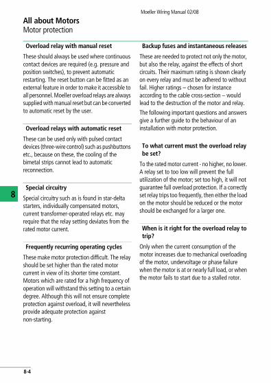
Overload relay with manual reset
These should always be used where continuous contact devices are required (e.g. pressure and position switches), to prevent automatic restarting. The reset button can be fitted as an external feature in order to make it accessible to all personnel. Moeller overload relays are always supplied with manual reset but can be converted to automatic reset by the user.
Overload relays with automatic reset
These can be used only with pulsed contact devices (three-wire control) such as pushbuttons etc., because on these, the cooling of the bimetal strips cannot lead to automatic reconnection.
Special circuitry
Special circuitry such as is found in star-delta starters, individually compensated motors, current transformer-operated relays etc. may require that the relay setting deviates from the rated motor current.
Frequently recurring operating cycles
These make motor protection difficult. The relay should be set higher than the rated motor current in view of its shorter time constant. Motors which are rated for a high frequency of operation will withstand this setting to a certain degree. Although this will not ensure complete protection against overload, it will nevertheless provide adequate protection against non-starting.
Backup fuses and instantaneous releases
These are needed to protect not only the motor, but also the relay, against the effects of short circuits. Their maximum rating is shown clearly on every relay and must be adhered to without fail. Higher ratings – chosen for instance according to the cable cross-section – would lead to the destruction of the motor and relay.
The following important questions and answers give a further guide to the behaviour of an installation with motor protection.
To what current must the overload relay be set?
To the rated motor current - no higher, no lower. A relay set to too low will prevent the full utilization of the motor; set too high, it will not guarantee full overload protection. If a correctly set relay trips too frequently, then either the load on the motor should be reduced or the motor should be exchanged for a larger one.
When is it right for the overload relay to trip?
Only when the current consumption of the motor increases due to mechanical overloading of the motor, undervoltage or phase failure when the motor is at or nearly full load, or when the motor fails to start due to a stalled rotor.
8-4

All about MotorsMotor protection
Moeller Wiring Manual 02/08
8
When does the overload relay fail to trip in good time although the motor is at risk?
With changes in the motor which do not cause an increase in current consumption: Effects of humidity, reduced cooling due to a reduction in speed or motor dirt, temporary additional external heating of the motor or bearing wear.
What causes destruction of the overload relay?
Destruction will take place only in the event of a short circuit on the load side of the relay when the back-up fuse is rated too high. In most cases, this will also endanger the contactor and motor. Therefore, always adhere to the maximum fuse rating specified on every relay.
3-pole overload relays should be so connected in the case of single-phase and DC motors so that all three poles of the overload relay carry the current, whether in single-pole or 2-pole circuits.
An important characteristic feature of overload relays conforming to IEC/EN 947-4-1 are the tripping classes (CLASS 10 A, 10, 20, 30). They determine different tripping characteristics for the various starting conditions of motors (normal starting to heavy starting).
1 pole 2 pole
8-5

All about MotorsMotor protection
Moeller Wiring Manual 02/08
8
Pick-up times
Response limits of time-delayed overload relays at all-pole load.
In the case of thermal overload relays with a current setting range, the response limits must apply equally to the highest and the lowest setting of the associated current.
Type of overload relay
Multiple of current setting Refer-ence ambi-ent temper-ature
At > 2 h starting from cold state of relay
Bt F 2 h
CTripping class
10 A102030
Tripping time in minutesF 2F 4F 8F 12
DTripping class
10 A102030
Tripping time in seconds
2 < T F 104 < T F 106 < T F 209 < T F 30
Non-ambient temperature compensated thermal relays and magnetic relays
1.0 1.2 1.5 7.2 + 40 °C
Ambient temperature compensated relay
1.05 1.2 1.5 7.2 + 20 °C
8-6

All about MotorsMotor protection
Moeller Wiring Manual 02/08
8
Response limits of 3-pole thermal overload relays at 2-pole load
In the case of thermal overload relays with a current setting range, the response limits must apply equally to the highest and the lowest setting of the associated current.
Overload capacity
Overload relays and releases have heating coils which can be thermally destroyed by overheating. The making and breaking currents of the motor flow in thermal overload relays which are used for motor protection. These currents are between 6 and 12 x Ie (rated operational current), depending on the utilization category and the size of the motor.
The point of destruction depends on the frame size and design and is usually approximately 12 to 20 x Ie.
The point of destruction is the point of intersection between the projected tripping curves and the multiple of the current.
Short-circuit rating of the main circuit
With currents that exceed the breaking capacity of the motor starter in relation to the utilization category (EN 60947-1), it is permissible for the current flowing during the operating time of the protective device to damage the motor starter.
The permissible behaviour of starters under short-circuit conditions is defined in the so-called types of co-ordination (1 and 2). It is common practice to state in the details of protective devices which type of co-ordination is ensured by them.
Type of thermal overload relay
Multiple of current setting Reference ambient temperature
At > 2 h, starting from cold state of relay
Bt F 2 h
Ambient temperature compensated, without phase-failure sensitivity
3 poles 1.0 2 poles1 pole
1.320
+ 20 °C
Non-ambient temperature compensated, without phase-failure sensitivity
3 poles 1.0 2 poles1 pole
1.250
+ 40 °C
Ambient temperature compensated, with phase-failure sensitivity
2 poles1 pole
1.00.9
2 poles1 pole
1.150
+ 20 °C
8-7
All about MotorsMotor protection
Moeller Wiring Manual 02/08
8
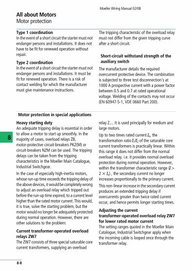
Type 1 coordinationIn the event of a short circuit the starter must not endanger persons and installations. It does not have to be fit for renewed operation without repair.
Type 2 coordinationIn the event of a short circuit the starter must not endanger persons and installations. It must be fit for renewed operation. There is a risk of contact welding for which the manufacturer must give maintenance instructions.
The tripping characteristic of the overload relay must not differ from the given tripping curve after a short circuit.
Short-circuit withstand strength of the auxiliary switch
The manufacturer details the required overcurrent protective device. The combination is subjected to three test disconnection's at 1000 A prospective current with a power factor between 0.5 and 0.7 at rated operational voltage. Welding of the contacts may not occur (EN 60947-5-1, VDE 0660 Part 200).
Motor protection in special applications
Heavy starting dutyAn adequate tripping delay is essential in order to allow a motor to start up smoothly. In the majority of cases, overload relays ZB, motor-protective circuit-breakers PKZ(M) or circuit-breakers NZM can be used. The tripping delays can be taken from the tripping characteristics in the Moeller Main Catalogue, Industrial Switchgear.
In the case of especially high-inertia motors, whose run-up time exceeds the tripping delay of the above devices, it would be completely wrong to adjust an overload relay which tripped out before the run-up time expired, to a current level higher than the rated motor current. This would, it is true, solve the starting problem, but the motor would no longer be adequately protected during normal operation. However, there are other solutions to the problem:
Current transformer-operated overload relays ZW7The ZW7 consists of three special saturable core current transformers, supplying an overload
relay Z.... It is used principally for medium and large motors.
Up to two times rated current Ie, the transformation ratio I1/I2 of the saturable core current transformers is practically linear. Within this range it does not differ from the normal overload relay, i.e. it provides normal overload protection during normal operation. However, within the transformer characteristic range (I > 2 x Ie) , the secondary current no longer increases proportionally to the primary current.
This non-linear increase in the secondary current produces an extended tripping delay if overcurrents greater than twice rated current occur, and hence permits longer starting times.
Adjusting the current transformer-operated overload relay ZW7 for lower rated motor currentThe setting ranges quoted in the Moeller Main Catalogue, Industrial Switchgear apply when the incoming cable is looped once through the transformer relay.
8-8

All about MotorsMotor protection
Moeller Wiring Manual 02/08
8
If the current transformer-operated overload relay ZW7 is required to provide protection to a motor of below 42 A rating (minimum value in the setting range of 42 A to 63 A), the necessary range adjustment is achieved by looping the incomer several times through the aperture in the relay. The change in the rated motor current quoted on the rating plate is inversely proportional to the number of loops.
Example:With the ZW7-63 relay, which has a setting range from 42 A to 63 A, a motor rating of 21 A to 31.5 A can be accommodated by looping the leads twice through the relay.
Bridging of motor protection during starting
For small motors the bridging of the motor protection during starting is more economical. Because of the additional parallel contactor, the overload relay does not carry the full current during starting. Only when the motor has reached full speed is the bridging contactor switched off and the full motor current is then
carried by the overload relay. Provided it has been set correctly to the rated motor current, this will ensure full motor protection during operation. Starting must be monitored.
The motor is a limiting factor with regard to the tripping delay of the current transformer-operated relay and the bridging period. One must ensure that the motor is able to tolerate the high temperature generated by direct starting, for the prescribed starting time. Motor and starting procedure have to be selected carefully when dealing with machines having a very large rotating mass, which are practically the only ones subject to this problem when direct starting is used.
Depending on the operating conditions adequate protection of the motor winding may no longer be given by an overload relay. In that case it must be weighed up whether an electronic motor-protective relay ZEV or a thermistor overload relay EMT 6 in conjunction with an overload relay Z meets the requirements.
Star-delta starter (y D)1 operating directionChangeover time with overload relay in positionA: < 15 s B: > 15 < 40 s C: > 40 s
Setting of the overload relay0.58 x Ie 1 x Ie 0.58 x IeFull motor protection in Y (star) position
Only partial motor protection in y position
Motor not protected in Y (star) position
-Q11A
-Q15 -Q13
Ie
-Q11
B
-Q15 -Q13
Ie
-Q11 -Q15 -Q13
Ie
C
8-9

All about MotorsMotor protection
Moeller Wiring Manual 02/08
8
Heavy starting duty
Multi-speed switches2 speeds2 separate windings
One tapped winding 3 speeds1 x tapped winding+ 1 winding
Attention must be paid to short-circuit protection of the overload relays.Separate supply leads should be provided if required.
-Q17 -Q21 -Q17-Q23 -Q21 -Q17-Q23 -Q21-Q11
Current transformer-operated overload relays ZW7
Bridging of motor protection during starting
Bridging during starting using bridging relay
For medium and large motors
For small motors; no protection during starting
Automatic cut out
-Q11 -Q11 -Q12 -Q11 -Q12
8-10

All about MotorsMotor protection
Moeller Wiring Manual 02/08
8
Individually compensated motor
Capacitor connected
Ie = Rated motor operational current [A] Iw = Iw = Active current Proportion of motor
Ib =Ib = Reactive current rated operational current [A]Ic = Rated capacitor current [A] Ic =
IEM = Setting current of overload relay [A] Ic = cos v = Motor power factorUe = Rated operational voltage [V]Pc = Rated capacitor output [kvar]C = Capacitance of capacitor [mF]
Iexy A[ ]
} Ie2
Iw2– A[ ]
Ue 3 2πf C 10 6– A[ ]××××Pc 103×
3 Ue×------------------
to contactor terminals to motor terminals
Setting IEM of overload relay
Capacitor does not relieve loading of cable between contactor and motor.
Capacitor relieves loading of cable between contactor and motor; normal arrangement.
-Q11PC
IEM
-Q11
PC
IEM
IEM 1 Ie×= IEM Iw2 Ib Ic–( )+ 2=
8-11
All about MotorsMotor protection
Moeller Wiring Manual 02/08
8
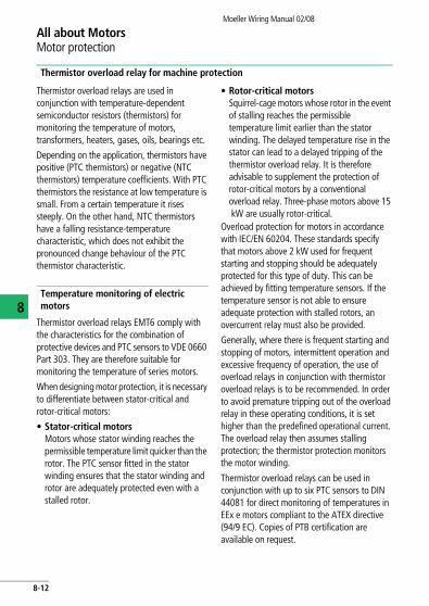
Thermistor overload relay for machine protection
Thermistor overload relays are used in conjunction with temperature-dependent semiconductor resistors (thermistors) for monitoring the temperature of motors, transformers, heaters, gases, oils, bearings etc.
Depending on the application, thermistors have positive (PTC thermistors) or negative (NTC thermistors) temperature coefficients. With PTC thermistors the resistance at low temperature is small. From a certain temperature it rises steeply. On the other hand, NTC thermistors have a falling resistance-temperature characteristic, which does not exhibit the pronounced change behaviour of the PTC thermistor characteristic.
Temperature monitoring of electric motors
Thermistor overload relays EMT6 comply with the characteristics for the combination of protective devices and PTC sensors to VDE 0660 Part 303. They are therefore suitable for monitoring the temperature of series motors.
When designing motor protection, it is necessary to differentiate between stator-critical and rotor-critical motors:
• Stator-critical motorsMotors whose stator winding reaches the permissible temperature limit quicker than the rotor. The PTC sensor fitted in the stator winding ensures that the stator winding and rotor are adequately protected even with a stalled rotor.
• Rotor-critical motorsSquirrel-cage motors whose rotor in the event of stalling reaches the permissible temperature limit earlier than the stator winding. The delayed temperature rise in the stator can lead to a delayed tripping of the thermistor overload relay. It is therefore advisable to supplement the protection of rotor-critical motors by a conventional overload relay. Three-phase motors above 15 kW are usually rotor-critical.
Overload protection for motors in accordance with IEC/EN 60204. These standards specify that motors above 2 kW used for frequent starting and stopping should be adequately protected for this type of duty. This can be achieved by fitting temperature sensors. If the temperature sensor is not able to ensure adequate protection with stalled rotors, an overcurrent relay must also be provided.
Generally, where there is frequent starting and stopping of motors, intermittent operation and excessive frequency of operation, the use of overload relays in conjunction with thermistor overload relays is to be recommended. In order to avoid premature tripping out of the overload relay in these operating conditions, it is set higher than the predefined operational current. The overload relay then assumes stalling protection; the thermistor protection monitors the motor winding.
Thermistor overload relays can be used in conjunction with up to six PTC sensors to DIN 44081 for direct monitoring of temperatures in EEx e motors compliant to the ATEX directive (94/9 EC). Copies of PTB certification are available on request.
8-12

All about MotorsMotor protection
Moeller Wiring Manual 02/08
8
Protection of current and temperature-dependent motor-protective devices
+ Full protection(+) Partial protection- No protection
Protection of the motor under the following conditions
Using bimetal
Using thermistor
Using bimetal and thermistor
Overload in continuous operation + + +
Extended starting and stopping (+) + +
Switching to stalled rotor (stator-critical motor)
+ + +
Switching on stalled rotor (rotor-critical motor)
(+) (+) (+)
Single-phasing + + +
Intermittent operation – + +
Excessive frequency of operation – + +
Voltage and frequency fluctuations + + +
Increased coolant temperature – + +
Impaired cooling – + +
8-13

Moeller Wiring Manual 02/08
8
All about MotorsEngineering notes
Three-phase automatic startersAutomatic stator starters three-phase current with startup resistorsSingle or multi-step resistors are connected upstream of the three-phase squirrel-cage motors to reduce the starting current and torque.With single-step starters, the starting current is approximately three times the motor full-load current. With multi-step starters, the resistors can be so designed that the starting current is only 1.5 to 2 times the motor full-load current, with a very low level of starting torque.
Three-phase autotransformer starters with starting transformersThis type of starting is preferable where the same starting torque is to be obtained as with the primary resistance starters but the starting current taken from the mains is to be further reduced. A reduced voltage Ua (approximately 70 % of the rated operational voltage) is supplied to the motor when starting via the starting transformer. Thus, the current taken from the mains is reduced to approximately half the direct starting current.
Three-phase automatic rotor starters with starting resistorsResistors are connected in the rotor circuit of the motor to reduce the starting current of motors with slip-ring rotors. The current taken from the mains is thus reduced. In contrast to stator resistance starters, the torque of the motor is practically proportional to the current taken from the mains. The number of steps of the automatic starter is determined by the maximum permissible starting current and by the type of the motor.
I: Line currentMd: Torquen: Speeda Reduction of the line currentb Reduction of the torque
a
b
20 40 60 80n
100 %
II
I'
Md
Md
M'd
a
20 40 60 80 100 %
b
n
II
I'Md
Md
M'd
20 40 60 80 100 %n
I Md
8-14

All about MotorsEngineering notes
Moeller Wiring Manual 02/08
8
Important data and features of three-phase automatic starters
1) Type of starter Stator resistance starter (for squirrel-cage motors) Rotor starter (for slipring rotors)
2) Type of starter Star-delta switches
With starting resistors
With starting transformers
Rotor resistance starter
3) Number of starting stages
1 only Normally 1 Normally 1 Selectable (no longer selectable when current or torque have been determined)
4) Voltage reduction at the motor
0.58 x rated operational voltage
Selectable: a x rated operational voltage (a < 1) e.g. 0.58 as with yd starter
Selectable:0.6/0.7/0.75 x Ua (transformer tappings)
none
5) Starting current taken from mains
0.33 x inrush current at rated operational voltage
a x inrush current at rated operational voltage
Selectable (see 4) 0.36/0.49/0.56 x
inrush current at rated operational voltage
Selectable: from 0.5 to about 2.5 x
rated current
5a) Starting current at the motor
Selectable (see 4) 0.6/0.7/0.75 x Ie
6) Starting torque 0.33 x tightening torque at rated operational voltage
a2 x tightening torque at rated operational voltage
Selectable (see 4) 0.36/0.49/0.56 x
tightening torque at rated operational voltage
Selectable (see 5) from 0.5 to pull-out torque
7) Current and torque reduction
Proportional Current reduction less than torque reduction
Proportional Current reduction much greater than torque reduction. From pull-out torque to rated speed almost proportional
8) Approximate price (for similar data). DOL starting = 100 (with overload relay, enclosed)
150 – 300 350 – 500 500 – 1500 500 – 1500
8-15

All about MotorsEngineering notes
Moeller Wiring Manual 02/08
8
Switching of capacitors
DIL contactors for capacitors – individual switching
When capacitors are switched on, contactors are heavily stressed by transient current peaks. When a single capacitor is switched on, currents up to 30 times the rated current can occur; these can, however, be reliably switched by Moeller DIL contactors.
When installing capacitors, the VDE specification 0560 part 4 (Germany) and the standards which apply to each country should be observed. According to these, capacitors not directly connected to an electrical device which forms a discharge circuit, should be equipped with a rigidly connected discharge device. Capacitors connected in parallel to the motor do not require a discharge device, since discharging is performed via the motor winding. No switch-disconnectors or fuses must be installed between the discharge circuit and the capacitor.
A discharge circuit or discharge device must reduce the residual voltage of the capacitor to
less than 50 V within a minute of the capacitor being switched off.
Individual compensation Group compensation
L1...3
-F1
-Q11 -Q31
-M1
-C1M3
L1...3
-F1
-Q11
-M1
-C1 M3
M3
M3
-M2 -M3
8-16
All about MotorsEngineering notes
Moeller Wiring Manual 02/08
8
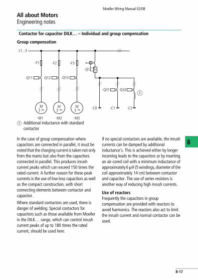
Contactor for capacitor DILK… – Individual and group compensation
In the case of group compensation where capacitors are connected in parallel, it must be noted that the charging current is taken not only from the mains but also from the capacitors connected in parallel. This produces inrush current peaks which can exceed 150 times the rated current. A further reason for these peak currents is the use of low-loss capacitors as well as the compact construction, with short connecting elements between contactor and capacitor.
Where standard contactors are used, there is danger of welding. Special contactors for capacitors such as those available from Moeller in the DILK… range, which can control inrush current peaks of up to 180 times the rated current, should be used here.
If no special contactors are available, the inrush currents can be damped by additional inductance's. This is achieved either by longer incoming leads to the capacitors or by inserting an air-cored coil with a minimum inductance of approximately 6 mH (5 windings, diameter of the coil approximately 14 cm) between contactor and capacitor. The use of series resistors is another way of reducing high inrush currents.
Use of reactorsFrequently the capacitors in group compensation are provided with reactors to avoid harmonics. The reactors also act to limit the inrush current and normal contactor can be used.
Group compensation
a Additional inductance with standard contactor
L1...3
-F1
-Q11
M3
-F2 -F3
-Q12 -Q13
-Q1
M3
M3
-Q31 -Q32a
-C0 -C1 -C2
-M1 -M2 -M3
I >
8-17

Moeller Wiring Manual 02/08
8
All about MotorsCircuit documents
General
Circuit documents serve to explain the function of circuits or electrical connections. They provide information for the construction, installation and maintenance of electrical installations.
The supplier and the operator must agree on the form in which the circuit documents are to be produced: paper, film, diskette, etc. They must also agree on the language or languages in which the documentation is to be produced. In the case of machines, user information must be written in the official language of the country of use to comply with EN 292-2.
The circuit documents are divided into two groups:
Classification according to the purpose
Explanation of the mode of operation, the connections or the physical position of the components. This support covers:
• Explanatory circuit diagrams,• Block diagrams,• Equivalent circuit diagrams,• Explanatory tables or diagrams,• Flow diagrams, tables• Time flow diagrams, tables• Wiring diagrams,• Device wiring diagrams,• Interconnection diagrams,• Terminal diagrams,• Assignment diagrams.
Classification according to the type of representation
Simplified or detailed
• Single-line or multi-line representation• Connected, semi-connected or separate
representation• Topographical representationIn addition to this, there is the process-orientated representation with the function chart (see previous pages).
Examples for drawing up circuit documents are given in IEC 1082-1, IEC/EN 61082-1.
Circuit diagrams
Diagrams indicate the voltage-free or current-free status of the electrical installation. A distinction is drawn between:
• Block diagram: Simplified representation of a circuit with its main parts, which shows how the electrical installation works and how it is subdivided.
• Circuit diagram: Detailed representation of a circuit with its individual components, which shows how the electrical installation works.
• Equivalent circuit diagram: Special version of an explanatory circuit diagram for the analysis and calculation of circuit characteristics.
8-18

All about MotorsCircuit documents
Moeller Wiring Manual 02/08
8Wiring diagrams
Wiring diagrams show the conductive connections between electrical components. They show the internal and/or external connections but, in general, do not give any information about the mode of operation. Instead of wiring diagrams, wiring tables can also be used.
• Unit wiring diagram: Representation of all the connections within the device or combination of devices.
• Interconnection diagram: Representation of the connections between the device or combination of devices within an installation.
• Terminal diagram: Representation of the connection points of an electrical installation and the internal and external conductive connections connected to them.
• Assignment diagram (location diagram). Representation of the physical position of the electrical equipment, which does not have to be to scale.
You will find notes on the marking of electrical equipment in the diagram as well as further diagram details in the section “Specifications, Formulae, Tables”.
Circuit diagram: 1-pole and 3-pole representation
M3 ~
Q1
Q11 Q121 3 5
2 4 6
1 3 5
2 4 6
M3 ~
U V W
PE
Q12
1 3 5
2 4 6
L1L2L3
13
14Q
Q11
L1, L2, L3
I > I > I >I >
8-19
Moeller Wiring Manual 02/08
8
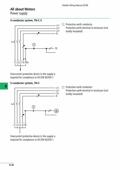
All about MotorsPower supply
4-conductor system, TN-C-Sa Protective earth conductor
Protective earth terminal in enclosure (not totally insulated)
Overcurrent protective device in the supply is required for compliance to IEC/EN 60204-1
5-conductor system, TN-Sa Protective earth conductor
Protective earth terminal in enclosure (not totally insulated)
Overcurrent protective device in the supply is required for compliance to IEC/EN 60204-1
L1 L2 L3 N PEN
PE
NL31L21L11
�
NL31L21L11
L1 L2 L3 N PE
�
8-20

All about MotorsPower supply
Moeller Wiring Manual 02/08
8
3-conductor system, IT
Overcurrent protective device is required in the supply for compliance to IEC/EN 60204-1For all systems: use the N conductor only with the agreement of the user
Separate primary and secondary protection
Earthed control circuit. In non-earthed control circuit, remove link and provide insulation monitoring.
L31L21L11
L1 L2 L3
PE
1
L1L3
5
2
3
64I�
L01L02
0
I� I�
8-21

All about MotorsPower supply
Moeller Wiring Manual 02/08
8
Combined primary and secondary protection
Earthed control circuit. In non-earthed control circuit, remove link and provide insulation monitoring.Maximum ratio of U1/U2 = 1/1.73 Circuit not to be used with STI/STZ (safety and isolating transformers).
L1L3
1 5
2
3
64
I> I> I>
L01L02
0
8-22
Moeller Wiring Manual 02/08
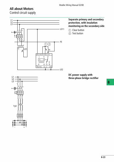
All about MotorsControl circuit supply
8
Separate primary and secondary protection, with insulation monitoring on the secondary side
a Clear buttonb Test button
DC power supply with three-phase bridge rectifier
L1
L3
1 5
2
3
64
I. I. I.
L011
PE
0
L02
L01
A1
R <
A1
L 15
A2
15 S1 S2 E
E
E
16
16 18
18 L A2
ab
L2
L1
L3
1 5
2
3
64I� I� I�
L2
Yy0
– +
8-23

Moeller Wiring Manual 02/08
8
All about MotorsContactor markings
The contactors in contactor combinations have, in accordance with EN 61346-2 for equipment and function, the code letter Q, as well as numerical identification, which shows the function of the component (e.g. Q22 = mains
contactor with anticlockwise rotation for high speed).
The following table shows the marking used in this Wiring Manual and in Moeller circuit documentation.
With contactor combinations which are made up of several basic types, the basic type is always maintained. Thus, the circuit diagram for a reversing star-delta starter, for example, is formed by combining the basic circuit of the reversing contactor and that of the standard star-delta starter.
Type of component
Mains contactors Step contactors
Standard motor 2 speed/4 speed
3 speed
One speed Low speed High speed
For-ward Up Hoist
Re-verse Down Lower
For-ward Up Hoist
Re-verse Down Lower
For-ward Up Hoist
Re-verse Down Lower
Star Delta Start-ing stage
Notes
DIL (/Z) Q11
DIUL (/Z) Q11 Q12
SDAINL (/Z) Q11 Q13 Q15
SDAIUL (/Z) Q11 Q12 Q13 Q15
UPIL (/Z/Z) Q17 Q21 Q23
UPIUL (/Z/Z) Q17 Q18 Q21 Q22 Q23
UPSDAINL (/Z) Q17 Q21 Q23 Q19
U3PIL (/Z/Z/Z) Q11 Q17 Q21 Q23
UPDIUL (/Z) Q17 Q21
ATAINL (/Z) Q11 Q13 Q16 to Qn
1-n start-ing stages
DAINL Q11
DDAINL Q11
DIL + discharge resistors
Q11 Q14
DIGL + discharge resistors
Q11
8-24

Moeller Wiring Manual 02/08
All about MotorsDirect-on-line start of three-phase motors
8
Typical circuits with DIL contactors
Fuseless without overload relayShort-circuit protection1) and overload protection by means of PKZM motor-protective circuit-breaker or NZM circuit-breaker.
Fuses with overload relayShort-circuit protection2) for contactor and overload relay by means of fuses F1.
Short-circuit protection3) for contactor by means of fuses F1.
1) Protective device in the supply line in accordance with Moeller Main Catalogue, Industrial Switchgear or AWA installation instructions.
2) Fuse size in accordance with data on the rating plate of the overload relay.3) Fuse size in accordance with Moeller Main Catalogue, Industrial Switchgear (Technical data for contactors)
L1 L3
1 5
2
3
64
L2
13
14
1 53
2 64
-Q1
PE
U V W
-Q11
M3
-M1
I > I > I >
L1 L3L2
1 53
2 64
PE
U V W
-Q11
M3
-M1
-F1
-F22 64 96
9597
98
L1 L3L2
1 53
2 64
PE
U V W
-Q11
M3
-M1
-F1
-F2
96
9597
98
8-25

All about MotorsDirect-on-line start of three-phase motors
Moeller Wiring Manual 02/08
8
Typical circuit with bridging of overload relay during starting
Control circuit device I: ON0: OFFFor connection of further control circuit devices a section "Pulse encoder", page 8-37
Method of operation: Actuation of pushbutton I energizes the coil of contactor Q11. The contactor switches on the motor and maintains itself after the button is enabled via its
own auxiliary contact Q11/14-13 and pushbutton 0 (three-wire control contact). Contactor Q0 is de-energized, in the normal course of events, by actuation of pushbutton 11. In the event of an overload, it is de-energized via the normally closed contact 95-96 on overload relay F2.
Without overload relay with overload relay
The short-circuit capacity of the contacts in the circuit has to be considered when selecting F0.Double actuator
L1(Q11/1)
-Q113
14
21
220
-S1113
14
13
14-Q11
A1
A2
-Q11
N
-F0
I
L1(Q11/1)
95
96
21
22
13
14
-F2
0
-S11
I
13
14-Q11
A1
A2-Q11
N
-F0
21 22
131496
1413 141321 22
Q11 Q11F2
0 I
A B
8-26

All about MotorsDirect-on-line start of three-phase motors
Moeller Wiring Manual 02/08
8
Application on drive motors with heavy starting duty
For connection when used with motor-protective circuit-breakers PKZM... and circuit-breakers NZM(H)... a section "Fuses with overload relays", page 8-29
L1 L3
2 64
L2
1 53
2 64
-F1
PEU V W
-Q11
M3
-M1
-F2
2 64
1 53
9698
97 95
-Q14
8-27

All about MotorsDirect-on-line start of three-phase motors
Moeller Wiring Manual 02/08
8
Function
Actuation of pushbutton I energizes bridging contactor Q14 which then maintains itself via Q14/13-14. At the same time, voltage is applied to the timing relay K1. The mains contactor Q11 is closed via Q14/44-43 and maintains itself via Q11/14-13. When the set time has elapsed, which corresponds to the starting time of the motor, bridging contactor Q14 is disconnected by K1/16-15. K1 is likewise disconnected and, exactly like Q14, cannot be energized again until after the motor has been switched off by pressing pushbutton 0. The normally closed
contact Q11/22-21 prevents Q14 and K1 closing whilst the motor is running. In the event of an overload, normally closed contact 95-96 on overload relay F2 effects de-energization.
Q14:Bridging contactorK1: Timing relaysQ11:Mains contactor
Control circuit deviceI: ON0: OFFFor connection of further control circuit devices a section "Pulse encoder", page 8-37
-Q11
-Q14 -Q14 -Q11
-K1
-K1
L1 (Q11/1)
-F295
96
21
22
0
-S11
16
15
13
14
-Q11A1
A2-Q14
N
-F0
13
14-Q1
13
1413
14 43
44
21
22
A1
A2
A1
A2
I
Q14 Q1196 2214
13 14
21
22
13 14
21 22
F2
0
-S11
I
A B
8-28
All about MotorsDirect-on-line start of three-phase motors
Moeller Wiring Manual 02/08
8
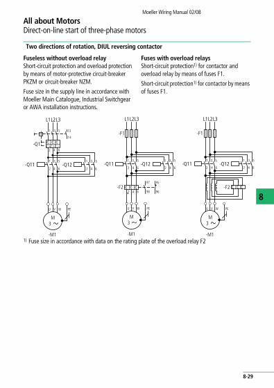
Two directions of rotation, DIUL reversing contactor
Fuseless without overload relayShort-circuit protection and overload protection by means of motor-protective circuit-breaker PKZM or circuit-breaker NZM.
Fuse size in the supply line in accordance with Moeller Main Catalogue, Industrial Switchgear or AWA installation instructions.
Fuses with overload relaysShort-circuit protection1) for contactor and overload relay by means of fuses F1.
Short-circuit protection1) for contactor by means of fuses F1.
1) Fuse size in accordance with data on the rating plate of the overload relay F2
L1 L3L2
1 53
2 64
U V W
M3
-M1
-Q1
1 53
2 64
1 53
2 64-Q11 -Q12
13
14
PE
I > I > I >
L1 L3L2
1 53
U V W
M3
-M1
2 64-Q11 -Q12
1 53
2 64
2 64
-F1
-F2
PE
96
97 95
98
L1 L3L2
U V W
M3
-M1
2 64-Q12
1 53
2 64
-F1
PE
-F2
-Q111 53
8-29

All about MotorsDirect-on-line start of three-phase motors
Moeller Wiring Manual 02/08
8
Changing direction of rotation after actuation of the 0 push-button
Changing direction of rotation without actuation of the 0 push-button
Q11: Mains contactor, clockwiseQ12: Mains contactor, anticlockwise
Control circuit device(three-way pushbutton)I = Clockwise0 = StopII = Anticlock-wise
-Q11 -Q12
-Q11
-Q11
-Q12
95
96
21
22
13
14
21
22
13
14
13
1413
14
21
22
13
14
A1
A2
A1
A2
21
22
21
22
L1(Q11/1)
0
-S11
-Q12
N
-F0
-Q1
I
I
II
-F2
II
-Q11 -Q12
-Q11
-Q11
-Q12
95
96
21
22
13
14
13
1413
14
21
22
A1
A2
A1
A2
21
22
21
22
13
14
21
22
13
14
L1(Q11/1)
0
-S11
-Q12
N
-F0
-Q1
I
I
II
-F2
II
Q12
0
-S11
I
Q12
21 22
13 14Q11
96F2
1413 1413
21 22
A B
1413
C
21 22
13II
Q12 Q12Q111314Q11
96F2
13 14
-S11 21
221413 1413
21
22
A B
1413
C
21 22
0I II
8-30

All about MotorsDirect-on-line start of three-phase motors
Moeller Wiring Manual 02/08
8
Operating principle: Actuation of pushbutton I energizes the coil of contactor Q11. It switches on the motor running clockwise and maintains itself after pushbutton I is enabled via its own auxiliary contact Q11/14-13 and pushbutton 0 (three-wire control contact). The normally closed contact Q11/22-21 electrically inhibits the closing of contactor Q12. When pushbutton II is pressed, contactor Q12 closes (motor running
anticlockwise). Depending on the circuit, direction can be changed from clockwise to anticlockwise either after pressing pushbutton 0, or by directly pressing the pushbutton for the reverse direction. In the event of an overload, normally closed contact 95-96 of overload relay F2, normally open contact 13-14 of the motor-protective circuit-breaker or the circuit-breaker will switch.
Operating direction and two speeds (reversing contactor)
Special circuit (tapped winding) for feed drives, etc.
FORWARD: feed or high speedRETRACT: high speed onlySTOP: tapped winding
1 53
L1 L3L2
-F1
2 64
PE
M3
-M1
97 95
98 96
1 53
2 64
1 53
2 64
2 64 2 64
2 64
1 53
-F297 95
98 96
-F21
-Q23
1U
1V
1W
2U
2V
2W
-Q17 -Q22 -Q21
8-31

All about MotorsDirect-on-line start of three-phase motors
Moeller Wiring Manual 02/08
8
Operating principle: Forward travel is initiated by pressing pushbutton I or II according to the speed required. Pushbutton I switches on the feed motion via Q17, which maintains itself via its normally open contact 13-14. If the feed movement is to occur at high speed, star contactor Q23 is energized via pushbutton II which energizes high speed contactor Q21 via its normally open contact Q23/13-14. Both contactors are maintained via Q21/13-14. A direct switch over from feed to high-speed during the forward travel is possible.
High speed reverse is initiated by pushbutton III. Contactor relay K1 picks up and energizes star contactor Q23 via K1/14-13. High-speed contactor Q22 is energized via normally open contacts K1/43-44 and Q23/44-43, and is maintained via Q22/14-13. The reverse motion can only be stopped via pushbutton 0. Direct changeover/reversal is not possible.
0: StopI : Low speed – FORWARD
(Q17)II: High speed – FORWARD
(Q21 + Q23)III: High speed – BACK
(Q22 + Q23)
Q17: Feed forwardQ21: High speed forwardQ23: Star contactorK1: Contactor relayQ22: Retract high speed
L1 (Q17/1)
-F2/F2195
96
21
22
0
-S11
13
14
A1
A2N
-F0
13
14
44
21
22
III
21
22
13
14
22
21
I13
I
II
14
21
-Q22
-Q21
-Q23
-Q17 -Q21
-Q23
31
32
-Q17 -Q17
-Q22
-Q23A1
A2
22
21
A1
A2
13
14
-Q17
22
21-K1 -Q21
-K1
-K1
13
14
A1
A2-Q22
-Q23
-K1
A1
A2
43
43
44
31
32
31
32
21
22
-Q2113
14-Q22
13
14
21
22
III
22
II
8-32

Moeller Wiring Manual 02/08
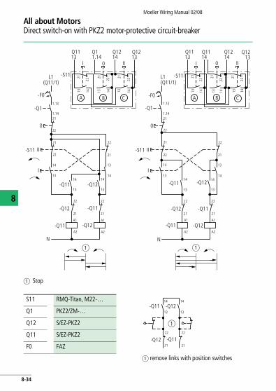
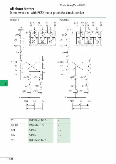
All about MotorsDirect switch-on with PKZ2 motor-protective circuit-breaker
8
Reversing
Instead of the high-capacity contact modules S-PKZ2, contact module SE1A…-PKZ2 can also be used provided a switching capacity of the circuit-breaker of 30 kA/400 V is sufficient.
L1 L3L2
U V W
M3
-M1
-Q1
-Q11
I > I > I >
13
14
T1 T3T2
L1 L3L2
T1 T3T2
L1 L3L2
-Q1213
14
21
22
I>> I>>I>>
A1
A2
21
11
T1 T3T2
A1
A2
I>> I>> I>>
8-33
All about MotorsDirect switch-on with PKZ2 motor-protective circuit-breaker
Moeller Wiring Manual 02/08
8
a Stop
a remove links with position switches
Q12Q12 Q12
L1(Q11/1)
-Q1
21
220
-S11
13
14
I
A1
A2
-Q11
-F0
-Q12
-Q11
-Q11
-Q12
21
22
-S11
Q11
21
22
13Q11
1413
1313Q11
13Q1214
0I 0I II
-S11
A B C
II
141321
22
21
221413
1.13
1.14
II21
22
13
14
13
14
13
14
21
22
21
22
A1
A2
-Q12
Q11.14 14 14
L1(Q11/1)
A B C
21
221413 1413
21
22
21
221413
-Q1
21
220
-F01.13
1.14
-S11
21
22II
21
22
13
14
21
22
13
14
I
-Q11 -Q1213
14
13
14
-Q12 -Q1121
22
A1A1
A2A2
-Q12-Q11
N N
a a
S11 RMQ-Titan, M22-…
Q1 PKZ2/ZM-…
Q12 S/EZ-PKZ2
Q11 S/EZ-PKZ2
F0 FAZ
-Q11
-Q12
14 14
13 13
22 22
21 21-Q11
-Q12
a
8-34

All about MotorsDirect switch-on with PKZ2 motor-protective circuit-breaker
Moeller Wiring Manual 02/08
8
Two speeds
Instead of the high-capacity contact modules S-PKZ2, contact module SE1A…-PKZ2 can also be used provided a switching capacity of the circuit-breaker of 30 kA/400 V is sufficient.
-Q1
M3
-M1
1U
1V
1W
2U
2V
2W
L1 L3L2
-Q21
T1 T3T2
-Q17A1
A2
2113
L1 L3L2 1.13 1.21
1.14 1.22
L1 L3L2 1.13 1.21
1.14 1.22
-Q2
2214
T1 T3T2
A1
A2
2113
2214
T1 T3T2
I > I >I >I > I > I >
I>> I>>I>> I>> I>>I>>
n < n >
1W 1V
1U
2W 2V
2U
8-35
All about MotorsDirect switch-on with PKZ2 motor-protective circuit-breaker
Moeller Wiring Manual 02/08
8
Version 1 Version 2Q21
13Q17
13Q2114
Q21.14
0I II
Q213
Q17
0I II1.14
L1(Q17/1)
-F0
-Q1
0
-S11
I
II
21
22
1.13
1.14
21
22 21
22
13
14
-Q1713
14
21
221413
-S11
A B1413
21
22
1413
13
14
13
14
21
22
A1
A2
N
-Q21.13
1.14
22
21
n>
n<-Q21
-Q21
-Q17
-Q17
-Q21
21
22
A1
A2
n>n<
C
L1(Q17/1)
-F0
-Q1
-Q2
021
22
1.13
1.14
1.13
1.14
-S11
Q1714
Q2114
Q21
21 221413
A B
141321
22
1413
22
21
C
-S11 II
n>
I
n<
21
22 21
22
13
1413
14
-Q1713
14
13
14
-Q21
-Q21 21
22
-Q1721
22
-Q17A1
A2
-Q21A1
A2
N
n>n<
13
Stop Stop
S11 RMQ-Titan, M22-… –
Q1, Q2 PKZ2/ZM-…/S –
Q21 S-PKZ2 n >
Q17 S-PKZ2 n <
S11 RMQ-Titan, M22-… –
8-36

Moeller Wiring Manual 02/08
All about MotorsControl circuit devices for direct-on-line start
8
Typical example of circuits with contactors DILM…
Pulse encoder
Illuminated pushbutton actuators
Two two-way pushbuttons
Double actuator pushbutton with indicator light
T0-1-15511 spring-return switch with automatic return to position 1
T0-1-15366 spring-return switch with automatic return to rest position
Maintained contact sensors
Changeover switch T0-1-15521 with fleeting contact in the intermediate position
MCS pressure switches
0 IQ11
21
1314Q11
96F2
13 14
Q11A2
13 14
2122 22
X1 X2
0 I
Q111314Q11
96F2
13 14
21 22
-S11
I 0
-S11
13 14
21 22 21 22 21 22
13 14 13 14
A B BA
0
Q111314Q11
96F2
1314
2122
I
2122
1314
A B C
Q11A2
0
Q111314
Q1196F2
1
01
21
34
S11
Start
Start
Q111314
Q1196F2
0 1
21
34
I
0 1I
S11
Start
Q111314Q11
96F2
21
34
I ON0OFF
0 1
S11
Q11A1
F296
-S12
2
1
4IP >
8-37

Moeller Wiring Manual 02/08
8
All about MotorsStar-delta switching of three-phase motors
Star-delta starters with overload relay
Arrangement in the motor lineIn a standard circuit configuration, the star-delta starter with overload relay, including a thermally delayed overcurrent relay are situated in the cables leading to the motor terminals U1, V1, W1 or V2, W2, U2. The overload relay can also be operated in a star circuit as it is usually connected in series with the motor winding and the relay current flowing through it = rated motor current x 0.58.For the complete circuit diagram a section "Automatic star-delta starters SDAINL", page 8-40.
Arrangement in the mains supply lineInstead of the arrangement in the motor line, the overload relay can be placed in the mains supply line. The section shown here indicates how the circuit differs from that on a section "Automatic star-delta starters SDAINL", page 8-40. For drives where the F2 relay trips out when the motor is starting in the star circuit, the F2 relay rated for the rated motor current can be switched in the mains line. The tripping delay is thus increased by approximately four to six times. In the star circuit the current also flows through the relay but here the relay does not offer full protection since its limit current is increased to 1.73 times the phase current. It does, however, offer protection against non-starting.
1 53
U1 V1 W1
2 64-Q11
2 64-F2
96
97 95
98
2 64-Q11
-F296
97 95
98
-F1
2 64
1 53
U1 V1 W1
8-38
All about MotorsStar-delta switching of three-phase motors
Moeller Wiring Manual 02/08
8
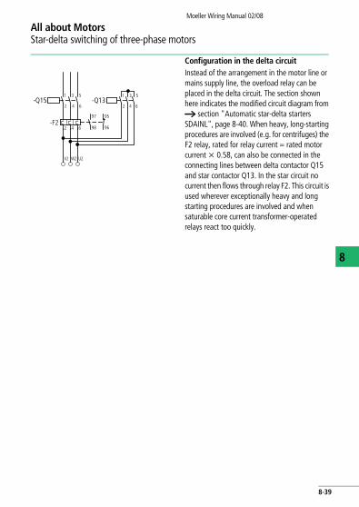
Configuration in the delta circuitInstead of the arrangement in the motor line or mains supply line, the overload relay can be placed in the delta circuit. The section shown here indicates the modified circuit diagram from a section "Automatic star-delta starters SDAINL", page 8-40. When heavy, long-starting procedures are involved (e.g. for centrifuges) the F2 relay, rated for relay current = rated motor current x 0.58, can also be connected in the connecting lines between delta contactor Q15 and star contactor Q13. In the star circuit no current then flows through relay F2. This circuit is used wherever exceptionally heavy and long starting procedures are involved and when saturable core current transformer-operated relays react too quickly.
2 64
-Q15
-F296
97 95
98
2 64
1 53
U2W2V2
-Q131 53
2 64
8-39

All about MotorsStar-delta switching of three-phase motors
Moeller Wiring Manual 02/08
8
Automatic star-delta starters SDAINL
Arrangement and rating of protective devices
Rating of switchgearQ11, Q15 = 0.58 x IeQ13 = 0.33 x Ie
Position A Position B
F2 = 0,58 x Ie with F1 in position B ta F 15 s
Q1 = Ie ta > 15 – 40 s
Motor protection in y and d configuration Only partial motor protection in y configuration
M3
-M1
U1
V1
W1
W2
U2
V2
L1 L3L2
2 64-Q15
-F296
97 95
98
2 64
1 53
-Q131 53
-F1
1 53
2 64
1 53
2 64
-Q11
B
-Q1
A
PE
2 64
13
14
21
22
I > I >I >
8-40

All about MotorsStar-delta switching of three-phase motors
Moeller Wiring Manual 02/08
8
Further notes on the configuration of the overload relay a section "Automatic star-delta starters SDAINL", page 8-40.
SDAINLM12 to SDAINLM55Pushbutton actuators
K1: Timing relay approx. 10 sQ11: Mains contactorQ13: Star contactorQ15: Delta contactorDouble actuator
FunctionPushbutton I energizes timing relay K1. The normally open contact K1/17-18 (instantaneous contact) which applies voltage to star contactor Q13, which closes and applies voltage to mains contactor Q11 via normally open contact Q13/14-13.
Q11 and Q13 maintain themselves via the normally open contacts Q11/14–13 and Q11/44–43. Q11 applies voltage to motor M1 in star connection.
SDAINLM70 to SDAINLM260
S110
(–)N
Q11
Q13
Q13
Q15
K1
I
Q11
Q11
Q15Q13
K1
Q15
N Y
K1
21
22
13
14
A2
A1
A2
A1
53
54
22
21
28
1717
18
14
13
53
54
53
54
A2
A1
A2
A1
22
21
S110
(–)N
Q11
Q13
Q13
Q15
K1
I
Q11
Q11
Q15Q13
K1
Q15
N Y
K1
21
22
13
14
A2
A1
A2
A1
13
14
22
21
28
1717
18
14
13
13
14
43
44
A2
A1
A2
A1
22
21
8-41
All about MotorsStar-delta switching of three-phase motors
Moeller Wiring Manual 02/08
8
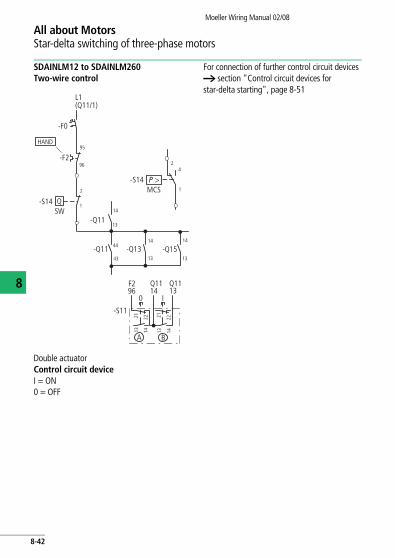
SDAINLM12 to SDAINLM260 Two-wire control
Double actuatorControl circuit deviceI = ON0 = OFF
For connection of further control circuit devices a section "Control circuit devices for star-delta starting", page 8-51
44
2
43 13
14
L1 (Q11/1)
-F0
95
96-F2
13
14
13
14
-S14
-Q11 -Q13 -Q15
-Q11
-S14MCSP >
24
1
SWQ
1
Q11
21 22
1314Q11
96F2
0 I
1413 141321 22
A B
-S11
HAND
8-42
All about MotorsStar-delta switching of three-phase motors
Moeller Wiring Manual 02/08
N
8
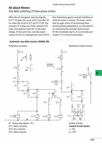
When the set changeover time has elapsed, K1/17-18 opens the circuit of Q13 and after 50 ms closes the circuit of Q15 via K1/17-28. Star contactor Q13 drops out. Delta contactor Q15 closes and switches motor M1 to full mains voltage. At the same time, normally closed contact Q15/22-21 interrupts the circuit of Q13
thus interlocking against renewed switching on while the motor is running. The motor cannot start up again unless it has previously been disconnected by pushbutton 0, or in the event of an overload by the normally closed contact 95-96 of overload relay F2, or via normally open contact 13-14 of the circuit-breaker.
Automatic star-delta starters SDAINL EM
Pushbutton actuators Maintained contact sensors
K1: Timing relay approx. 10 sQ11: Mains contactorQ13: Star contactorQ15: Delta contactor
Double actuatorControl circuit deviceI = ON0 = OFF
L1 (Q11/1)
-F295
96
0
-S11
13
14
A1
A2
-F0
44
21
22
2
13
14
I
-Q11
-Q15
-K1A1
A2
A1
A2
A1
A2-Q15-Q13
43
44
43-Q11 -Q13
-F0
95
96
-F2
13
14
-S14
13
1413
14
-Q1
-Q1114
13
22
21-Q13
-Q11
-S14MCS
24
1
SWQ
-K1
22
21
16
15
18 -Q13
1
L1 (Q11/1)
Q11
21
22
4414Q11
96F2
0 I
1413 141321 22
A B-S11
-Q11
P >
HAND
8-43
All about MotorsStar-delta switching of three-phase motors
Moeller Wiring Manual 02/08
8
For connection of further control circuit devices a section "Control circuit devices for star-delta starting", page 8-51
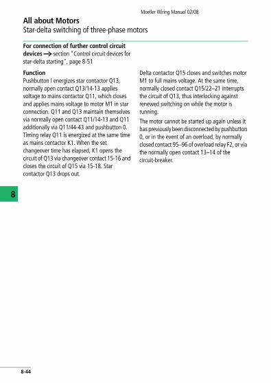
FunctionPushbutton I energizes star contactor Q13, normally open contact Q13/14-13 applies voltage to mains contactor Q11, which closes and applies mains voltage to motor M1 in star connection. Q11 and Q13 maintain themselves via normally open contact Q11/14-13 and Q11 additionally via Q11/44-43 and pushbutton 0. Timing relay Q11 is energized at the same time as mains contactor K1. When the set changeover time has elapsed, K1 opens the circuit of Q13 via changeover contact 15-16 and closes the circuit of Q15 via 15-18. Star contactor Q13 drops out.
Delta contactor Q15 closes and switches motor M1 to full mains voltage. At the same time, normally closed contact Q15/22–21 interrupts the circuit of Q13, thus interlocking against renewed switching on while the motor is running.
The motor cannot be started up again unless it has previously been disconnected by pushbutton 0, or in the event of an overload, by normally closed contact 95–96 of overload relay F2, or via the normally open contact 13–14 of the circuit-breaker.
8-44

All about MotorsStar-delta switching of three-phase motors
Moeller Wiring Manual 02/08
8
Automatic reversing star-delta starter SDAIUL
Reversing
Rating of switchgearQ11, Q12: Ie
F2, Q15 : 0,58 x IeQ13 : 0,33 x IeThe maximum motor output is limited by the upstream reversing contactor, and is lower than with automatic star-delta starters for only one direction of operation
Standard version: Relay current = motor rated current x 0.58
For other arrangements of overload relay a section "Star-delta starters with overload relay", page 8-38
M3
-M1
U1
V1
W1
W2
U2
V2
L1 L3L2
2 64-Q12
-F296
97 95
98
2 64
-Q151 53
-F1
1 53
2 64
1 53
2 64-Q11
-Q1
PE
2 64
131 3 5
14
21
22
-Q131 53
2 64
I > I > I >
8-45

All about MotorsStar-delta switching of three-phase motors
Moeller Wiring Manual 02/08
8
Changing direction of rotation after actuation of the 0 pushbuttonThree-way pushbuttonControl circuit devicesI = Clockwise0 = StopII = Anticlockwise
L1 (Q11/1)
-F2
0
-S11
A1
A2
N
-F0
44
13
14
II
-Q11 -K1A1
A2-Q15-Q13
43
44
43-Q11
-Q1
-Q11
-Q11
I
21
22
95
96
21
22
-Q12
13
14
13
14-Q12
-K1-K1
-Q1213
14
13
14
II
I21
22
21
22
A1
A2
-Q15 -Q1321
22
-Q12A1
A2
A1
A2
21
22
21
2218
17
28
17
0
Q1213 14Q11
96F2
13 14
21 22
I
13 14
A B C
13Q12
II
13 14
21 22 21 22
-S11
8-46

All about MotorsStar-delta switching of three-phase motors
Moeller Wiring Manual 02/08
8
For connection of further control circuit devices a section "Control circuit devices for star-delta starting", page 8-51
FunctionPushbutton I energizes contactor Q11 (e.g. clockwise). Pushbutton II energizes contactor Q12 (e.g. anticlockwise). The contactor first energized applies voltage to the motor winding and maintains itself via its own auxiliary contact 14-13 and pushbutton 0. Normally open contact 44-43 fitted to each mains contactor energizes star contactor Q13, which energizes and switches on motor M1 in the star connection. At the same time, timing relay K1 is triggered. When the set changeover time has elapsed, K1/17-18 opens the circuit of Q13, which drops out. K1/17-28 closes the circuit of Q15.
Delta contactor Q15 energizes and switches motor M1 to the delta configuration, i.e. full mains voltage. At the same time, normally closed contact Q15/22–21 interrupts the circuit of Q13, thus interlocking against renewed switching on while the motor is running. Motor direction can be changed, either after pressing pushbutton 0, or by direct actuation of the reverse button, depending upon the circuit. In the event of an overload, disconnection is effected by normally closed contact 95–96 of overload relay F2.
Changing direction of rotation without actuation of the 0 pushbuttonThree-way pushbuttonControl circuit devicesI = Clockwise0 = StopII = Anticlockwise
L1 (Q11/1)
-F2
0
-S11
A1
A2
N
-F0
44
13
14
II
-Q11 -K1A1
A2-Q15-Q13
43
44
43-Q11
18
17
-Q1
-Q11
-K1
-Q11
I
21
22
95
96
21
22
-Q12
13
14
13
14-Q12 -Q12 13
14
13
14
II
I21
22
21
22
A1
A2
-K1
-Q15 -Q1321
22
-Q12A1
A2
A1
A2
21
22
21
2228
17
21
22
13 14 96
1413 1413
Q11Q11 F2
0I
A B
13Q12
14Q12
II
-S11 21 22 21 221413
C
8-47

Moeller Wiring Manual 02/08
8
All about MotorsStar-delta starting with motor-protective circuit-breakers PKZ2
With Icc > Icn short-circuit proof installation required.
L1 L2 L3
L1
-Q1
L2 L3
T1 T2 T3
L1 L2 L3
T1
13 21
14-Q11 -Q15 -Q13
22
13 21
14 22
T2 T3
1U
1V
1W
2V
2W
2U
-M1
L1 L2 L31 3 5
2 4 6
T1 T2 T3
Q13A1 13 21
14A2 22
L1
U F 690 V
U F 500 V
L2 L3
T1 T2 T3
1.13 1.21
1.14 1.22
A1
A2
A1
A2
M3
I>> I>> I>>
I>> I>> I>> I>> I>>I>>
I > I > I >
8-48
All about MotorsStar-delta starting with motor-protective circuit-breakers PKZ2
Moeller Wiring Manual 02/08
8
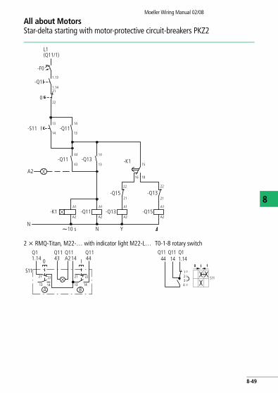
2 x RMQ-Titan, M22-… with indicator light M22-L… T0-1-8 rotary switch
L1(Q11/1)
-F0
1.13
1.1421
22
13
14
14
13
14
13
44
43
A1
A2
-Q1
-S11 -Q11
-Q11
-K1A1
A2
A1
A2
A1
A2-Q11
22
21
22
15
1816
21
-Q13
-Q13
-Q15
-Q15
10 s N YN
-Q13 -K1
A2
0
I
S11
1413
2221
1413
2221
A B
Q1
0 I1.14Q11 Q11 Q1143 A214 44
0 1
S11
Q1144
Q11.14
1234
Q1114
8-49

All about MotorsStar-delta starting with motor-protective circuit-breakers PKZ2
Moeller Wiring Manual 02/08
8
S11 RMQ-Titan, M22-…
Q1 PKZ2/ZM-…
dQ15 S/EZ-PKZ2
yQ13 DIL0M Ue F 500 V AC
yQ13 S/EZ-PKZ2 Ue F 660 V AC
K1 ETR4-11-A t t y (s) 15 – 40
Q11 S/EZ-PKZ2 N Motor protection (y) + d
F0 FAZ Setting l
8-50

Moeller Wiring Manual 02/08
All about MotorsControl circuit devices for star-delta starting
8
Automatic star-delta starters SDAINL
Pulse encoder
Illuminated pushbutton actuators Two two-way pushbuttons
Double actuator pushbutton with indicator light
Spring-return switch T0-1-15511 with automatic return to position 1.
Spring-return switch T0-1-15366 with automatic return to rest position.
Two-wire control
Changeover switch T0-1-15521 with fleeting contact in the intermediate position
e.g. selector switch Rotary switch T LS position switchesMCS pressure switches
F2 Q11 Q11 Q11 Q11
212213 14 13 14
2122
96 13
X1 X2
14
-S11
44 A20 I
F2
-S11 -S112113 14 13 14 13 14 13 14
22
21
22
21
22
21
22
0
A B A B
I 0 I96Q1114
Q1144
22
96 13
1321
14 13 14
21 22
A2 14 44F2
-S11
Q11 Q11 Q11 Q11
A B C
1
0
Q111314
Q1196F2
1
01
21
34
S11
Start
Start
Q111314
Q1196F2
0 1
21
34
I
0 1I
S11
Start
Q111314Q11
96F2
21
34
I ON0OFF
0 1
S11
Q1114
Q1144
F2
S14
96
8-51
All about MotorsControl circuit devices for star-delta starting
Moeller Wiring Manual 02/08
8
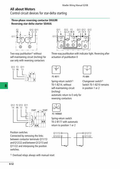
Three-phase reversing contactor DIULRRReversing star-delta starter SDAIUL
Two-way pushbutton1) without self-maintaining circuit (inching) for use only with reversing contactors
Three-way pushbutton with indicator light. Reversing after actuation of pushbutton 0
Spring-return switch1) T0-1-8214, without self-maintaining circuit (inching)automatic return to 0 only for reversing contactors
Changeover switch1) Switch T0-1-8210 remains in position 1 or 2
Spring-return switch T0-2-8177 with automatic return to position 1 or 2
Position switchesConnected by removing the links between contactor terminals Q11/13 and Q12/22 and between Q12/13 and Q11/22 and interposing the position switches.
1) Overload relays always with manual reset
-S11
22211413
22211413
I II
BA
13Q12
13Q11
96F2
13
-S11
22211413
22211413
22211413
I
A B D EC
Q11A2 21 96Q12
21 IIQ11
14Q12
13Q12F2
0
234
01 2
1
Q1213
F296
Q1113
FS 4011
01 2
FS 684
01 2
2
123456
01 STARTSTART
78
Q11F296 13
Q1213
Q1214
FS 140660
01 2
START START
Q11/13Q12/22
Q12/13Q11/22
8-52

Moeller Wiring Manual 02/08
All about MotorsPole-changing motors
8
The speed is determined by the number of poles on induction motors. Several speeds can be
obtained by altering the number of poles. The usual types are:
The various tapped winding configurations give differential output ratios for the two speeds
The d/y y configuration comes nearest to satisfying the most common requirement for constant torque. It has the additional advantage that, because nine terminals are available, y/d starting can be used to provide smooth starting or to reduce the starting current for the low speed condition (a section "Motor windings", page 8-56).
The y/y y is preferred for better matching of the motor to machines in which the torque increases by a quadratic factor (pumps, fans, rotary compressors). Moeller multi-speed starters can be used for both types of connection.
2 speeds – separate windings
In theory, motors with separate windings allow any combination of speed and any output ratio. Both windings are arranged in y connection and are completely independent of one another.
Preferred speed combinations are:
The code numbers are prefixed to the main notations to denote increasing speed. Example: 1U, 1V, 1W, 2U, 2V, 2W. Comparable to EN 60034-8.
2 speeds 1:2 1 reversible tapped winding
2 speeds 2 separate windings
3 speeds 1 reversible tapped winding 1:2, 1 separate winding
4 speeds 2 reversible tapped windings 1:2
2 speeds Tapped winding
Type of connection d/y y y/y yOutput ratio 1/1,5–1,8 0,3/1
Motors with tapped winding
1500/3000 – 750/1500 500/1000
Motors with separate windings
– 1000/1500 – –
Number of poles 4/2 6/4 8/4 12/6
Code no. low/high 1/2 1/2 1/2 1/2
8-53
All about MotorsPole-changing motors
Moeller Wiring Manual 02/08
8
Motor circuit
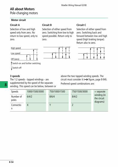
3 speedsThe 1:2 speeds - tapped windings - are supplemented by the speed of the separate winding. This speed can be below, between or
above the two tapped winding speeds. The circuit must consider it (a figure, page 8-84).
Preferred speed combinations are:
Circuit A
Selection of low and high speed only from zero. No return to low speed, only to zero.
Circuit B
Selection of either speed from zero. Switching from low to high speed possible. Return only to zero.
Circuit C
Selection of either speed from zero. Switching back and forward between low and high speed (high braking torque). Return also to zero.
High speed
Low speed
Off (zero)
Switch-on and further switching
Switch-off
Speeds 1000/1500/3000 750/1000/1500 750/1500/3000 = separate winding (in the circuit diagrams)
Number of poles
6/4/2 8/6/4 8/4/2
Connection
X Y Z
8-54

All about MotorsPole-changing motors
Moeller Wiring Manual 02/08
8
Motor circuit
4 speedsThe 1:2 speeds - tapped windings - can follow in sequence or overlap, as the following examples show:
For motors with 3 or 4 speeds the non-connected winding has to be opened at certain pole ratios to avoid inductive circulating currents. This is achieved with additional motor terminals. A range of rotary switches is equipped with this connection (a section "Multi-Speed Switches", page 4-7).
Circuit A
Selection of any speed only from zero. Return only to zero.
Circuit B
Selection of any speed from zero and from low speed. Return only to zero.
Circuit C
Selection of any speed from zero and from low speed. Return to low speed (high braking torque) or to zero.
3rd speed
2nd speed
1st speed
Off (zero)
1st winding 500/1000 2nd winding 1500/3000 = 500/1000/1500/3000
or 1st winding 500/1000 2nd winding 750/1500 = 500/750/1000/1500
8-55
Moeller Wiring Manual 02/08
8
All about MotorsMotor windings
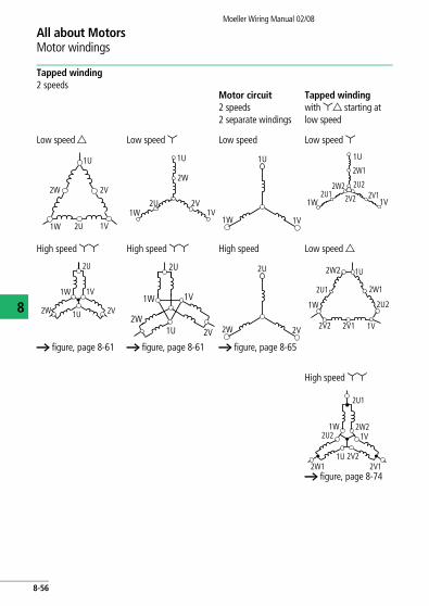
Tapped winding3 speedsMotor circuit X2 windings, medium and high speed – tapped winding
Motor circuit Y2 windings, low andspeed – tapped win
2 2
or 2 or 2
Low speed Separate winding1
Medium speed Separate winding1
a figure, page 8-83 a figure, page 8-8
2U
2W 2V
3W
3V3U
1U
1W
3W
3V3U
2U
2W 2V
3W 3V
3U
1U
1W 1
3W 3V
3U
1W 1V
1U
2W
2U
Tapped winding2 speeds
Motor circuit2 speeds2 separate windings
Tapped windingwith yd starting at low speed
Low speed d Low speed y Low speed Low speed y
High speed yy High speed yy High speed Low speed d
a figure, page 8-61 a figure, page 8-61 a figure, page 8-65
High speed yy
a figure, page 8-74
1U
1W 1V
2W 2V
2U
1U
1W 1V
2W
2V2U
1W 1V
1U 1U
1W 1V
2W1
2U22V12V22U1
2W2
1U
2U
1V1W
2W 2V
1U
2U
1W
2V
1V
2W2W 2V
2U
1V
1W
2W2 1U
2V12V2
2U2
2W12U1
1U 2V2
2U1
1V1W
2W1 2V1
2W22U2
8-56

All about MotorsMotor windings
Moeller Wiring Manual 02/08
Motor circuit2 speeds2 separate windings
Tapped windingwith yd starting at low speed
Low speed Low speed y
High speed Low speed d
a figure, page 8-65
High speed yy
a figure, page 8-74
V1W 1V
1U 1U
1W 1V
2W1
2U22V12V22U1
2W2
2W 2V
2U
1V
1W
2W2 1U
2V12V2
2U2
2W12U1
1U 2V2
2U1
1V1W
2W1 2V1
2W22U2
8
Tapped winding3 speedsMotor circuit X2 windings, medium and high speed – tapped winding
Motor circuit Y2 windings, low and high speed – tapped winding
Motor circuit Z2 windings, low and medium speed – tapped winding
2 2 2
or 2 or 2 or 2
Low speed Separate winding1
Medium speed Separate winding1
High speedSeparate winding1
a figure, page 8-83 a figure, page 8-85 a figure, page 8-87
2U
2W 2V
3W
3V3U
1U
1W 1V
3W
3V3U
1U
1W 1V
2W
2V2U
2U
2W 2V
3W 3V
3U
1U
1W 1V
3W 3V
3U
1U
1W 1V
2W 2V
2U
1W 1V
1U
2W 2V
2U
3W 3V
3U
8-57

NotesMoeller Wiring Manual 02/08
8
8-58

Moeller Wiring Manual 02/08
All about MotorsMulti-speed contactors
8
Certain operating sequences for multi-speed motors may be necessary, or undesirable, depending on the nature of the drive. If, for example, the starting temperature rise is to be reduced or high inertia loads are to be accelerated, it is advisable to switch to low speed first and then to high speed.
It may be necessary to prevent switching from high to low speed in order to avoid oversynchronous braking. In other cases, it should be possible to switch each speed on and off directly. The operating sequence and
indexing facilities of rotary switches allow for these possibilities. Multi-speed contactor starters can achieve these circuits by interlocking with suitable control circuit devices.
Fuse protection of the overload relaysWhen a common fuse is used in the supply line, it must not be larger than the back-up fuses specified on the rating plate of either overload relay, otherwise each relay must be protected by its own back-up fuse, as shown in the diagram.
L1
-F11
-Q17 -Q21
-F21 -F2
1 3 5
2 4 6
2 4 6
1 3 5
2 4 6
2 4 6
97
98
95
96
L2 L3
97
98
95
96
-F1
8-59
All about MotorsMulti-speed contactors
Moeller Wiring Manual 02/08
8
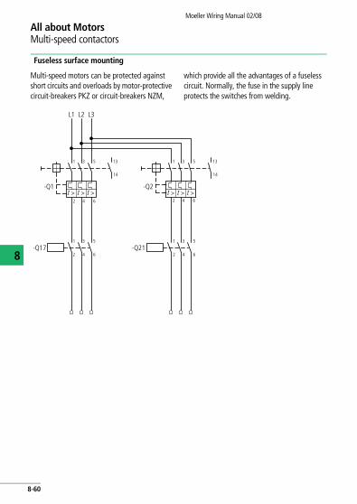
Fuseless surface mounting
Multi-speed motors can be protected against short circuits and overloads by motor-protective circuit-breakers PKZ or circuit-breakers NZM,
which provide all the advantages of a fuseless circuit. Normally, the fuse in the supply line protects the switches from welding.
L1
-Q1
-Q17 -Q21
1
I > I > I >
3 5
1 3 5
2 4 6
1 3 5
2 4 6
2 4 6
13
14
L2 L3
-Q2
1
I > I > I >
3 5
2 4 6
13
14
8-60
Moeller Wiring Manual 02/08
All about MotorsMulti speed switches of three-phase motors
8
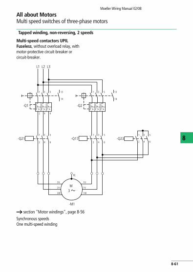
Tapped winding, non-reversing, 2 speeds
Multi-speed contactors UPILFuseless, without overload relay, with motor-protective circuit-breaker or circuit-breaker.
a section "Motor windings", page 8-56
Synchronous speedsOne multi-speed winding
L1
-Q1
-Q21 -Q17
PE
M
-M1
2U
2V
2W
1U
1V
1W3
1
I > I > I >
3 5
1 3 5
2 4 6
1 3 5
2 4 6-Q23
1 3 5
2 4 6
2 4 6
13
14
L2 L3
-Q2
1
I > I > I >
3 5 13
14
8-61

All about MotorsMulti speed switches of three-phase motors
Moeller Wiring Manual 02/08
8
Rating of switchgear
Q2, Q17: I1 (low speed)Q1, Q21: I2 (high speed)Q23: 0.5 x I2
Motor terminals 1U, 1V, 1W 2U, 2V, 2W
Number of poles 12 6
rpm 500 1000
Number of poles 8 4
rpm 750 1500
Number of poles 4 2
rpm 1500 3000
Contactors Q17 Q21, Q23
8-62

All about MotorsMulti speed switches of three-phase motors
Moeller Wiring Manual 02/08
8
Circuit A (a figure, page 8-55) One three-way pushbutton
For connection of further control circuit devices a figure, page 8-69, a figure, page 8-70, a figure, page 8-71
FunctionPushbutton I energizes mains contactor Q17 (low speed), wich maintains itself via its normally open contact 13-14. Pushbutton II energizes star contactor Q23 and via its normally open contact 13-14 mains contactor Q21. Q21 and Q23 maintain themselves via normally open contact 13-14 of Q21.
Speed can be changed either after pressing pushbutton 0 (circuit A) or directly by pressing the appropriate pushbutton (circuit C), depending upon the circuit. The motor can be switched off either by pressing pushbutton 0, or in the event of an overload, by normally open contact 13–14 of the circuit-breaker.
Three-way pushbuttonI: Low speed (Q17)0: StopII: high speed
(Q21 + Q23)Q17: Mains contactor, low speedQ23: Star contactorQ21: Mains contactor, high speed
L1(Q11/1)
-F0
-Q1
-Q2
0
II
-S11
-Q17
-Q17 -Q23
N
-Q23
-Q21
I
13
14
13
14
21
22
21
22
14
13
14
13
21
2222
21A1
A2
A1
A2-Q21
-Q17
-Q23
-Q21
22
21
13
14
A1
14
II
I
22
14
13
21
13
A2
-S11
14 1313I II0
A B C
96
21 22
13 14
21 22
13 14
21 22
13 14
Q17 F21 Q21 Q21
8-63

All about MotorsMulti speed switches of three-phase motors
Moeller Wiring Manual 02/08
8
Circuit C (a figure, page 8-55) One three-way pushbutton
For connection of further control circuit devices a figure, page 8-72
Three-way pushbuttonI: Low speed (Q17)0: StopII: High speed (Q21 + Q23)
Q17: Mains contactor, low speedQ23: Star contactorQ21: Mains contactor, high speed
L1(Q11/1)
-F0
-Q1
-Q2
0
II
-S11
-Q17
-Q17 -Q23
N
-Q23
-Q21
I
13
14
13
14
21
22
21
22
14
13
14
13
22
2121
22A1
A2
A1
A2-Q21
-Q23
-Q17
-Q21
22
21
13
14
A1
14
II
I
22
14
13
21
13
A2
14
-S11
Q1714Q21
13Q21
13I II0
A B C
Q1796F21
21
22
13 14
21
22
13 14
21 22
13 14
8-64

All about MotorsMulti speed switches of three-phase motors
Moeller Wiring Manual 02/08
8
Two separate windings, non-reversing, two speeds
Multi-speed contactor UPDIUL, fuseless without overload relay
Rating of switchgear
Q1, Q17 = I1 (low speed)Q2, Q21 = I2 (high speed)
Motor windings a section "Motor windings", page 8-56.
L1
-Q1
-Q17 -Q21
PE
M
-M1
1U
1V
1W
2U
2V
2W3
1
I > I > I >
3 5
1 3 5
2 4 6
1 3 5
2 4 6
2 4 6
13
14
L2 L3
-Q2
1
I > I > I >
3 5
2 4 6
13
14
8-65

All about MotorsMulti speed switches of three-phase motors
Moeller Wiring Manual 02/08
8
Two separate windings, non-reversing, two speeds
Multi-speed contactor UPDIUL, with fuses and overload relay
Fuse size in accordance with data on the rating plate of overload relays F2 and F21. If overload relays F2 and F21 cannot be protected by a common fuse, then use circuit a figure, page 8-59.
Motor windings a section "Motor windings", page 8-56.
L1
F1
F1
F21 F2
M1
1W
1V
1U
2W
2V
2U
Q17 Q211 3 5
2 4 6
9698
9597
9698
9597
2 4 6
1 3 5
2 4 6
2 4 6
L2 L3
M3
8-66
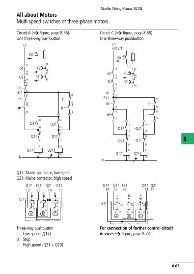
All about MotorsMulti speed switches of three-phase motors
Moeller Wiring Manual 02/08
8
Circuit A (a figure, page 8-55)One three-way pushbutton
Circuit C (a figure, page 8-55)One three-way pushbutton
Q17: Mains contactor, low speedQ21: Mains contactor, high speed
Three-way pushbuttonI: Low speed (Q17)0: StopII: High speed (Q21 + Q23)
For connection of further control circuit devices a figure, page 8-73.
L1
FO
F2
F21
Q113
1413
21
2221
2214
13
14
13
22
21
A1
A2
A1
13
14
14
1321
22
95
9695
96
21
A2
14Q2
0S11
Q17
Q21 Q17
Q21
I
II
Q17 Q21
N
II
I
22
L1(Q17/1)
-F0
0-S11
A1
A2
A1
A2
II
I II
22
21
-Q21
22
21
95
96
22
21
22
21
14
13
-Q21
-Q17
-Q21
-Q17
14
13
N
-F21
-F2
FL1
14
13
14
13
-Q1
-Q2
95
96
14
13
-Q1722
21
14
13
I
-S11
14Q21
13Q21
13I II0
A B C
Q1796F21
21 22
13 14
21 2213 14
21 22
13 14
13 14
21 22-S11
A
Q2113
Q2114
Q1714
I 0 II
F2196
Q1713
B C
21 22
13 14
21 22
13 14
8-67

All about MotorsMulti speed switches of three-phase motors
Moeller Wiring Manual 02/08
8
Operating principleActuation of pushbutton I energizes the coil of contactor Q17,which switches on the low speed of the motor and, after pushbutton I is released, maintains itself via its auxiliary contact 13-14 and pushbutton 0.
Speed can be changed either after pressing pushbutton 0, or directly by pressing the appropriate pushbutton, depending upon the circuit. The motor is switched off either by pressing pushbutton 0, or in the event of an overload, by normally closed contact 95–96 of overload relays F2 and F21.
8-68

Moeller Wiring Manual 02/08
All about MotorsControl circuit devices for UPDIUL multi-speed contactors
8
Two separate windings, non-reversing, two speeds
Circuit A (a figure, page 8-55)
One three-way pushbutton with indicator lights
Control circuit devices
I : Low speed (Q17)0: StopII : High speed (Q21)
-F0
L1
0
A1
A2
A1
A2
II
I
22
21
-Q21
22
21
22
21
14
13
-Q21
-Q17
-Q21
14
13
N
95
96
14
13-Q17
14
13
I
-Q1722
21
II
-F2/F21
22
21
A
B D
B
-S11
I 021 II13
A B C D E
21 21
13
22 22 22
14 13
211314 14
Q17A2
Q2121
Q1714
Q2113Q21
96F21
8-69

All about MotorsControl circuit devices for UPDIUL multi-speed contactors
Moeller Wiring Manual 02/08
8
Circuit A (a figure, page 8-55)
Two three-way pushbuttons
Control circuit devices
I: Low speed (Q17)0: StopII: High speed (Q21)Remove existing links and rewire
-F0
L1
95
21
2221
22
21
22
22
21
22
21
21
14
13
14
13
22
21
13
1413
14
22
22
21
13
14
13
14
96-F2/F21
0a
0b
IIb
Ib
IIa
IIbIIa
-Q17
-Q21
-Q21
-Q17A B
IaIb
Ia
13
A
96
B C BA C
-S11 -S11
Ia
21
221413 1413 1413
21
22
21
22
21
221413 1413 1413
21
22
21
22
IIa0a Ib IIb0b
Q2113Q17
14Q21F21
8-70
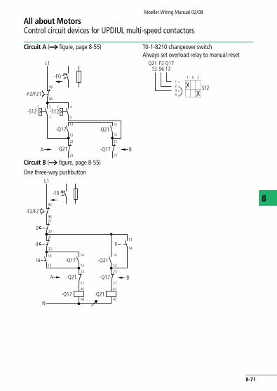
All about MotorsControl circuit devices for UPDIUL multi-speed contactors
Moeller Wiring Manual 02/08
8
Circuit A (a figure, page 8-55) T0-1-8210 changeover switchAlways set overload relay to manual reset
Circuit B (a figure, page 8-55)
One three-way pushbutton
L1
95
96-F2/F21
-S12
-Q17
-Q21 -Q17
-Q21
-S12
A B
1 2
1 3
14
13
22
14
13
21
22
21
2 4
-F0
S12
Q2113
F296
Q1713
1 0 21234
L1
95
9621
22
21
22
14
13
14
13
13
14
14
13
22
21
A1
A2
A1
A2
22
21
-F0
-F2/F21
0
II
I
A B
II
N
-Q21 -Q17
-Q17 -Q21
-Q17 -Q21
8-71

All about MotorsControl circuit devices for UPDIUL multi-speed contactors
Moeller Wiring Manual 02/08
8
Circuit B(a figure, page 8-55)
Two three-way pushbuttons
Control circuit device for circuit B
-F0
L1
0a
-Q21
22
21
22
21
14
13-Q2114
13
95
96
-Q17
IIb
IIa
-F2(1)
22
21B
0b
2221
Ib
21
22
Ia IIa IIb14
1314
13
A
14
13
-Q1722
21
14
13
A
Q2113
F2196
B C
Q1714
Q1713
Ia
S11 S11
Q2114
0a IIa Ib 0b IIb
21 22
13 14
21 22
13 14
21 22
13 14
21 22
13 14
21 22
13 14
21 22
13 14
A B C
8-72
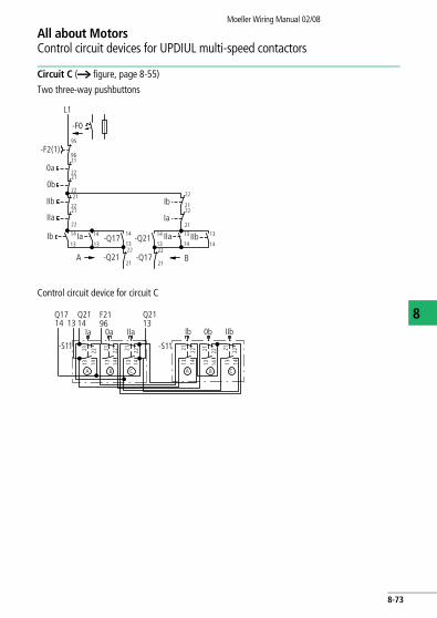
All about MotorsControl circuit devices for UPDIUL multi-speed contactors
Moeller Wiring Manual 02/08
8
Circuit C (a figure, page 8-55)
Two three-way pushbuttons
Control circuit device for circuit C
-F0
L1
0a
-Q21
22
21
22
21
14
13-Q21
14
13
95
96
14
13-Q17
IIb
-Q17
IIa
-F2(1)
22
21A B
0b
22
21
Ib22
21
Ia22
21
14
13IIa
Ib
Ia
IIb14
13
14
13
22
2122
21
-S11
A
Q2113
F2196
B C
Q1714 13
Ia
-S11
Q2114
0a IIa
21 22
13 14
21 2213 14
21 2213 14
Ib 0b IIb
A B C
21 22
13 14
21 2213 14
21 2213 14
8-73

Moeller Wiring Manual 02/08
8
All about MotorsMulti speed switches of three-phase motors
Tapped winding, non-reversing, 2 speeds
Multi-speed contactors UPSDAINLStar-delta starting at low speed
FuselessWithout overload relay
Rating of switchgearQ1, Q17 = I1
(low speed)Q2, Q21 = I2
(high speed)Q19, Q23 = 0,5 x I2
L1
PE
Y
-M1
3 2W1
2V1
2U1
1W1V1U
1 3 5
2 4
L2 L3
3 5
2 4 6
2 4 6-Q17
-Q23
-Q21
6
2W2
2V2
2U2
1 3 5
1
1 3 5
2 4 6
3 5
2 4 6
1
13
14
-Q1
-Q19
2 4 6
-Q214
131 3 5
I > I > I > I > I > I >
8-74

All about MotorsMulti speed switches of three-phase motors
Moeller Wiring Manual 02/08
8
With fuses and overload relays
Rating of switchgearF2, Q17 = I1
(low speed)F21, Q21 = I2
(high speed)Q19, Q23 = 0,5 x I2 F1 = I2
Overload relays F2 and F21 are not used on multi-speed contactors without motor protection. If F2 and F21 cannot be protected by a common fuse, then use circuit on a figure, page 8-59.
Motor windings a section "Motor windings", page 8-56.
L1
PE
Y
-M1
3
2W1
2V1
2U1
1W1V1U
L2 L3
5
2 4 6
-Q17
-Q23
-Q21
2W2
2V2
2U2
1 3 5
1
1 3 5
2 4 6
3 5
2 4 6
1
-F1
-Q19
2 4 6
-F21-F22 4 6
97 95
98 96
3
97 95
98 962 4 6
8-75
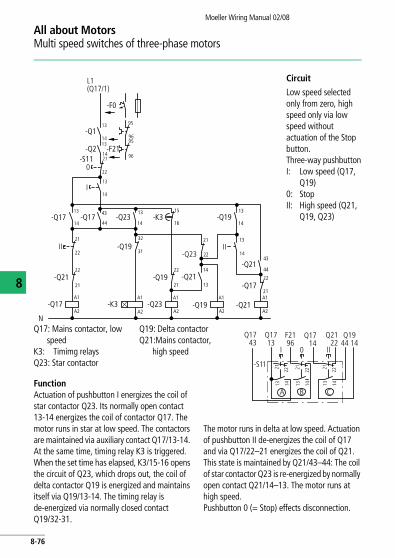
All about MotorsMulti speed switches of three-phase motors
Moeller Wiring Manual 02/08
8
FunctionActuation of pushbutton I energizes the coil of star contactor Q23. Its normally open contact 13-14 energizes the coil of contactor Q17. The motor runs in star at low speed. The contactors are maintained via auxiliary contact Q17/13-14. At the same time, timing relay K3 is triggered. When the set time has elapsed, K3/15-16 opens the circuit of Q23, which drops out, the coil of delta contactor Q19 is energized and maintains itself via Q19/13-14. The timing relay is de-energized via normally closed contact Q19/32-31.
The motor runs in delta at low speed. Actuation of pushbutton II de-energizes the coil of Q17 and via Q17/22–21 energizes the coil of Q21. This state is maintained by Q21/43–44: The coil of star contactor Q23 is re-energized by normally open contact Q21/14–13. The motor runs at high speed. Pushbutton 0 (= Stop) effects disconnection.
Circuit
Low speed selected only from zero, high speed only via low speed without actuation of the Stop button.Three-way pushbuttonI: Low speed (Q17,
Q19)0: StopII: High speed (Q21,
Q19, Q23)
Q17: Mains contactor, low speed
K3: Timimg relaysQ23: Star contactor
Q19: Delta contactorQ21:Mains contactor,
high speed
-F0
-F21
-Q1
-Q2-S11
-Q17
-Q21
-Q17
-Q17
21
21
A1
A2
N
22
22-Q21
-Q21
-Q21
-Q17
-Q23 -Q19
-Q19
-Q23
-Q19
-Q19
-K3
-K3A1
A2
A1
A2
A1
A2
31
32 21
22
21
A1
A2
21
22
44
43
22
13 15
1614
13
14
13
14
13
14
43
44
L1(Q17/1)
0
II
I
-Q23
14
13
22
21
95
9695
9614
13
14
13
14
13
II
-S11
A
Q1713
Q1944 14
F2196
B C
21 22
13 14
Q1743
Q1714
I 0 II
Q2122
21 22
13 14
21 22
13 14
8-76
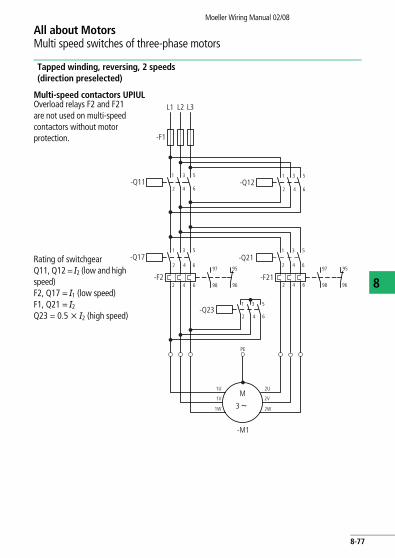
All about MotorsMulti speed switches of three-phase motors
Moeller Wiring Manual 02/08
8
Tapped winding, reversing, 2 speeds(direction preselected)
Multi-speed contactors UPIULOverload relays F2 and F21 are not used on multi-speed contactors without motor protection.
Rating of switchgearQ11, Q12 = I2 (low and high speed)F2, Q17 = I1 (low speed)F1, Q21 = I2 Q23 = 0.5 x I2 (high speed)
L1
PE
-M1
2W
2V
2U
1 3 5
2 4
L2 L3
-F1
2 4 6
2 4 6-Q11
97
-Q17
6
1W
1V
1U
1 3 5
-F2198
95
96 2 4 6
97
98
95
96-F2
2 4 6
1 3 5
2 4 6
1 3 5
2 4 6
1 3 5
M
3
-Q12
-Q21
-Q23
8-77
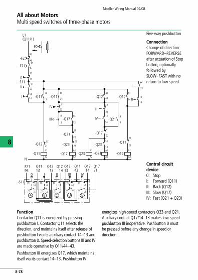
All about MotorsMulti speed switches of three-phase motors
Moeller Wiring Manual 02/08
8
FunctionContactor Q11 is energized by pressing pushbutton I. Contactor Q11 selects the direction, and maintains itself after release of pushbutton I via its auxiliary contact 14–13 and pushbutton 0. Speed-selection buttons III and IV are made operative by Q11/44–43.
Pushbutton III energizes Q17, which maintains itself via its contact 14–13. Pushbutton IV
energizes high-speed contactors Q23 and Q21. Auxiliary contact Q17/14–13 makes low-speed pushbutton III inoperative. Pushbutton 0 must be pressed before any change in speed or direction.
Five-way pushbutton
ConnectionChange of direction FORWARD–REVERSE after actuation of Stop button, optionally followed by SLOW–FAST with no return to low speed.
Control circuit device0: StopI: Forward (Q11)II: Back (Q12)III: Slow (Q17)IV: Fast (Q21 + Q23)
L1(Q11/1)
-F0
0-S11
A1
A2
A1
A2
-Q17
-Q17A1
A2
A1
A2N
-F21
-F2
III
II
14
13
22
21
-Q11
-Q17
-Q11 -Q21
14
13
22
21
95
96
2222
21
14
13
44
43-Q11
-Q21
95
96
21
A1
A2
22
21I
22
21
-Q1114
13
IV22
21
14
13III
22
21-Q23-Q12
-Q23
-Q23
21
22
14
13
-Q12
-Q2114
13IV
III21
22
-Q1244
43-Q1214
13
14
13
Q1113
I
F2196
13 14
21 22
-S11
A C
0
B D
Q1213
Q1214
Q1713
Q1143
Q1714
Q1721
II III IV
E
13 14
21
22
13 14
21
22
13 14
21 22
13 14
21
22
8-78

All about MotorsMulti speed switches of three-phase motors
Moeller Wiring Manual 02/08
8
Tapped winding, reversing, 2 speeds(Direction and speed selected simultaneously)
Multi-speed contactor UPIUL Fuseless without overload relay
Rating of switchgear
Q1, Q17, Q18 = I1 (low speed)
Q2, Q21, Q22 = I2
Q23 = 0.5 x I2 (high speed)
L1
PE
M
-M1
3 1W
1V
1U
2W
2V
2U
-Q23
1 3 5
2 4 6
L2 L3
-Q1I> I> I>
-Q2
1 3 5
2 4 6
1 3 5
2 4 6
1 3 5 1 3 5 1 3 5
1 3 5
2 4 6
2 4 6 2 4 6 2 4 6-Q17
I> I> I>
13
14
-Q18 -Q21 -Q22
13
14
8-79

All about MotorsMulti speed switches of three-phase motors
Moeller Wiring Manual 02/08
8
Multi-speed contactor UPIUL
With fuses and overload relays
Rating of switchgear
F2, Q17, Q18 = I1 (low speed)
F21, Q21, Q22 = I2Q23 = 0.5 x I2 (high speed)
Overload relays F2 and F21 are not used on multi-speed contactors without motor protection
L1
PE
M
-M1
3 1W
1V
1U
2W
2V
2U
1 3 5
2 4 6
L2 L3
-F2
1 3 5
2 4 6
1 3 5
2 4 6
-Q17
-F1
-Q18
97 95
98 96
-Q23
97 95
98 96
-F212 4 6
2 4 6-Q21 -Q22
1 3 5
2 4 6
1 3 5
2 4 6
8-80
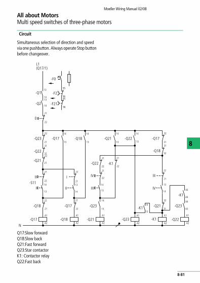
All about MotorsMulti speed switches of three-phase motors
Moeller Wiring Manual 02/08
8
Circuit
Simultaneous selection of direction and speed via one pushbutton. Always operate Stop button before changeover.
Q17:Slow forwardQ18:Slow backQ21:Fast forwardQ23:Star contactorK1: Contactor relayQ22:Fast back
L1(Q17/1)
N
-F0
0
-S11I
-Q18
A1
A2
A1
A2
-Q21
21
22
-Q21
14
13
22
21
95
96
II
22
21
-Q17
21
II
21
22
22
-Q23
21
-Q17
-Q22-Q23
-Q22
-Q21
-Q23
A1
A2
A1
A2
-Q23
-Q22
-Q18-Q17
22
-Q22
14
14
13
III
95
96
-F2
-F2114
13
-Q2
-Q1
-Q1713
31
32
-Q21
22
2122
21
-K1
I
14
13 14
13
IV
14
13
22 21 14
21 22 13-Q18 -K1
-K1A1
A2
14
13
44
43
A1
A2
-K143
44
14
13
32
31
III
IV
21
22
-Q1831
32
31
3214
13
14
13
8-81

All about MotorsMulti speed switches of three-phase motors
Moeller Wiring Manual 02/08
8
FunctionDesired speed and direction can be selected by actuation of the appropriate pushbutton. Contactors Q17, Q18, Q21 and Q23 maintain themselves by their contact 14–13 and can be de-energized only by actuation of pushbutton 0. Contactors Q21 and Q22 can maintain themselves only when Q23 has picked up and contact Q23/13/13–14 or 44–43 is closed.
Five-way pushbuttonControl circuit device0: StopI: Slow forward (Q17)II: Slow back (Q18)III: Fast forward (Q21 + Q23)IV: Fast back (Q22 + Q23)
Q1822
13 14
21 22
-S11
A
Q2121
Q2322
Q1721
I0 II
F2196
Q2314
Q1832
Q2232
III IV
B C D E
13 14
21 22 21 22
13 14
21 22
13 14
21 22
13 14
8-82
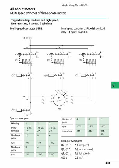
All about MotorsMulti speed switches of three-phase motors
Moeller Wiring Manual 02/08
8
Tapped winding, medium and high speed, Non reversing, 3 speeds, 2 windings
Multi-speed contactor U3PIL Multi-speed contactor U3PIL with overload relay a figure, page 8-85
Synchronous speed
Rating of switchgear
Q2, Q11 : I1 (low speed)
Q1, Q17 : I2 (medium speed)
Q3, Q21 : I3 (high speed)
Q23 : 0.5 x I3
L1
PE
M
-M1
3 3W
3V
3U
2W
2V
2U
1 3 5
2 4
L2 L3
-Q1I> I> I>
-Q2
1 3 5
2 4 6
1 3 5
2 4 6
1 3 5 1 3 5
1 3 5
2 4 6
2 4 6 2 4 6
-Q17
I> I> I>
13
14
-Q23
-Q11 -Q21
13
14
6
1W1V1U
13
14
2 4 6
I> I> I>-Q3
1 3 5
Winding 1 2 2
Motor terminals
1U, 1V, 1W
2U, 2V, 2W
3U, 3V, 3W
Number of poles
12 8 4
rpm 500 750 1500
Number of poles
8 4 2
rpm 750 1500 3000
Number of poles
6 4 2
rpm 1000 1500 3000
Contactors Q11 Q17 Q21, Q23
8-83

All about MotorsMulti speed switches of three-phase motors
Moeller Wiring Manual 02/08
8
FunctionPushbutton I energizes mains contactor Q11 (low speed), pushbutton II mains contactor Q17 (medium speed), pushbutton III star contactor Q23 and via its normally open contact Q23/14–13 mains contactor Q21 (high speed). All contactors maintain themselves by their auxiliary contact 13–14. Speed sequence from low to high is optional. Switching in steps from high to medium or low speed is not possible. The motor is always switched off by pressing pushbutton 0. In the event of an overload, normally open contact 13–14 of the
motor-protective circuit-breaker or circuit-breaker can also switch off.
Circuit of motor winding: XCircuit A
Circuit ASelection of any speed only from zero. No return to low speed, only to zero.
Circuit BSelection of any speed from zero or from low speed. Return only to zero.
Q11: Low speed winding 1Q17: Medium speed winding 2Q23: High speed winding 2Q21: High speed winding 2
4-way pushbutton0: StopI: Low speed (Q11)II: Medium speed (Q17)III: High speed (Q21 + Q23)
L1(Q17/1)
-F0
0
-S11
A1
A2
A1
A2
21
22
22
21
-Q17
21-Q23
-Q17
-Q23 -Q21A1
A2
A1
A2
-Q23
N
-Q17
14
13
III
14
13
-Q2-Q1
31
32
-Q3
III22
21
14
13
II14
13I
II
14
13
-Q1114
13
13
14
22
21
22
21
-Q2121
22
22
-Q11
-Q21
31
3232
31
-Q11 -Q17
-Q11
-Q21
-Q23
32
31
14
13
13 14
21 22
A
Q2113
Q1114
Q1714
I0 II
F2296
Q2114
III
B C D
13 14
21 22 21 22
13 14
21 22
13 14
13 14
21 22-S11
A
Q2113
Q1114
Q1714
I0 II
F2296
Q2314
III
B C D13 14
21 22 21 22
13 14
Q1113
Q1713
21 22
13 14
8-84
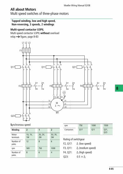
All about MotorsMulti speed switches of three-phase motors
Moeller Wiring Manual 02/08
8
Tapped winding, low and high speed, Non-reversing, 3 speeds, 2 windings
Multi-speed contactor U3PIL Multi-speed contactor U3PIL without overload relay a figure, page 8-83
Synchronous speed
Rating of switchgear
F2, Q17: I1 (low speed)
F3, Q11: I2 (medium speed)
F4, Q21: I3 (high speed)
Q23: 0.5 x I3
L1 L2 L3
1 3 5
M1
2 4 6
F1
97 95
98 96
Q17 Q111 3 5
2 4 6
F22 4 6
F397 95
98 962 4 6
Q211 3 5
2 4 6
F497 95
98 962 4 6
1 3 5
Q231 3 5
2 4 6
3U 3V 3W
2U
2V
2W
1U
1V
1W
M3
1 3 51 3 5
Winding 2 1 2
Motor terminals
1U, 1V, 1W
2U, 2V, 2W
3U, 3V, 3W
Number of poles
12 8 6
rpm 500 750 1000
Number of poles
8 6 4
rpm 750 1000 1500
Contactors Q17 Q11 Q21, Q23
8-85

All about MotorsMulti speed switches of three-phase motors
Moeller Wiring Manual 02/08
8
FunctionPushbutton I energizes mains contactor Q17 (low speed), pushbutton II mains contactor Q11 (medium speed), pushbutton III star contactor Q23 and via its normally open contact Q23/14–13 mains contactor Q21 (high speed). All contactors maintain themselves by their auxiliary contact 13–14.
Speed sequence from low to high is optional. Switching in steps from high to medium or low speed is not possible. The motor is always switched off by pressing pushbutton 0. In the event of an overload, normally closed contact 95–96 of overload relays F2, F21 and F22 can also switch off.
Circuit of motor winding: YCircuit A
Circuit ASelection of any speed only from zero. No return to low speed, only to zero.
Circuit BSelection of any speed from zero or from low speed. Return only to zero.4-way pushbutton0: StopI: Low speed (Q17)II: Medium speed (Q11)III: High speed (Q21 + Q22)
Q17: Low speed winding 1Q11: Medium speed winding 1Q23: High speed winding 2Q21: High speed winding 2
L1
F0
0
S2
S1
S3
S0
A1
A2
A1
A2
Q17
21
Q17 Q21
A1
A2
A1
A2
Q23
N
III
14
13
F3F2
F4
III
II
I
II
14
13
14
13
22
21
22
2121
2222
Q11
31
32
32
31
Q11 Q11
Q21
Q23
14
13
22
21
95
96
22
21
22
21
14
13
14
13
Q11
31
32Q21
Q23 Q2332
31
Q17 Q21
Q17
14
13
Q1714
13 14
21 22
-S11
A
Q2113
Q1114
I0 II
F2296
Q2114
III
B C D
21 22
13 14
21 22
13 14
21 22
13 14
Q2114
Q1713
Q2113
Q1113
Q1714
F2296 0 I II
-S11
13 14
21
22
13 14
21
22
13 14
21
22
13 14A B C D
Q1114
21
22
III
8-86

All about MotorsMulti speed switches of three-phase motors
Moeller Wiring Manual 02/08
8
Tapped winding, low and medium speed, Non-reversing, 3 speeds, 2 windings
Multi-speed contactor U3PIL Multi-speed contactor U3PIL without overload relay a figure, page 8-59
Synchronous speed
Rating of switchgear
F2, Q17: I1 (low speed)
F4, Q21: I2 (medium speed)
F3, Q11: I3 (high speed)
Q23: 0.5 x I3
L1 L2 L3
1 3 5
M1
2 4 6
F1
97 95
98 96
Q17 Q111 3 5
2 4 6
F22 4 6
F397 95
98 962 4 6
Q211 3 5
2 4 6
F497 95
98 962 4 6
1 3 5
Q231 3 5
2 4 6
3U 3V 3W
2U
2V
2W
1U
1V
1W
M3
1 3 51 3 5
Winding 2 2 1
Motor terminals
1U, 1V, 1W
2U, 2V, 2W
3U, 3V, 3W
Number of poles
12 6 4
rpm 500 1000 1500
Number of poles
12 6 2
rpm 500 1000 3000
Number of poles
8 4 2
rpm 750 1500 3000
Contactors Q17 Q21, Q23
Q11
8-87

All about MotorsMulti speed switches of three-phase motors
Moeller Wiring Manual 02/08
8
FunctionPushbutton I energizes mains contactor Q17 (low speed), pushbutton II mains contactor Q23 (low speed) and via its normally open contact Q23/14-13 mains contactor Q21 (high speed), pushbutton III mains contactor Q11. All contactors maintain themselves by their auxiliary contacts 13-14.
Speed sequence from low to high is optional. Switching in steps from high to medium or low speed is not possible. The motor is always switched off by pressing pushbutton 0. In the event of an overload, normally closed contact 95–96 of overload relays F2, F21 and F22 can also switch off.
Circuit of motor winding: ZCircuit A
Circuit ASelection of any speed from zero. No return to low speed, only to zero.
Circuit BSelection of any speed from zero or from low speed. Return only to zero.
Q17: Low speed winding 1Q23: Medium speed winding 2Q21: Medium speed winding 2Q11: High speed winding 1
4-way pushbutton0: StopI: Low speed (Q17)II: Medium speed (Q21 + Q23)III: High speed (Q11)
L1(Q17/1)
N
-F0
0
-S11
I
-Q11
A1
A2
A1
A2
-Q21
21
22
-Q21
14
13
22
21
-F2-F21-F22
95
96
III
II22
21
-Q1714
1322
21
14
13
II
21
2222
-Q2321
-Q17 -Q23 -Q21
-Q11
-Q17
-Q23A1
A2
A1
A2
-Q23
-Q11
-Q21
-Q17
14
13
32
31
32
31
22
21
32
31
32
31
-Q1114
13
14
13
14
13III
Q2113
Q1714
Q1114
F2296 0 I II III
13 14
21
22
A B C D
Q2114
21
22
21
22
21
22
13 14 13 14 13 14
-S11
II III0 I14
Q2313
Q2314
Q1713
Q1714
Q1113
Q1114
F2296
-S11
1321
22
13 14
21
22
13 14
21 22
13 14
A B C D
21 22
8-88

Moeller Wiring Manual 02/08
All about MotorsMulti speed switch with motor-protective circuit-breakers PKZ2
8
L1 L2 L3
-Q1
1 3 5
2 4 6-Q21
2U
2V
2W
1U
1V
1W
-Q2
U F 690 V
I> I> I>
L1 L2 L3 1.13 1.21
1.14 1.22
A1
A2
13
14
21
22I>>
T1 T2 T3
-Q17A1
A2
-M1
I>> I>>
I> I> I>
T1 T2 T3
-Q23
T1 T2 T3
L1 L2 L3 1.13 1.21
1.14 1.22
I>> I>> I>>
13
14
21
22
A1
A2-Q23
13
14
21
22
L1 L2 L3
I>> I>> I>>
U F500 V
M3 h
Number of poles 12 6
rpm 500 1000
Number of poles 8 4
rpm 750 1500
Number of poles 4 2
rpm 1500 3000
8-89

All about MotorsMulti speed switch with motor-protective circuit-breakers PKZ2
Moeller Wiring Manual 02/08
8
Circuit Aa figure, page 8-55 Circuit Ca figure, page 8-55
L1(Q17/1)
-Q21
13
14
21
22
-F0
II
I
-Q17
-Q23
-Q1
-S11
1.13
1.141.13
1.14-Q2
21
220
-S11
n >
n <
13
14
21
22
21
22
-Q17 -Q23A1
A2
N
-Q21
-Q23A1
A2
n >n <
A1
A2
13
14
-Q1721
22
-Q2113
14
13
14
21
22
-S11
21
22
13 14A
Q1713
21
22
13 14
21
22
13 14
B C
Q21.14
Q2114
Q2113
I 0 II
Q1713
Q21.14
Q2114
Q2113
L1(Q17/1)
-F0
-Q1
-Q2
0
II
I
n >
n <
1.13
1.141.13
1.1421
22
13
14
21
22
-Q1713
14
21
22
21
22
A1
A2
-Q21
-Q23
-Q17
A B C
21
22
13 14
21 22
13 14
21
22
13 14
I 0 II
13
14
21
22
-Q1721
22
-Q2113
14
-Q2313
14
-Q23A1
A2
A1
A2
n >n <
N
-S11
Q1714
-Q21
Stop Stop
S11 RMQ-Titan, M22-… – – –
Q1, Q21 PKZ2/ZM-…/S n> – –
Q2, Q17 PKZ2/ZM-…/S n < – –
Q23 DIL0M yn > Ue F 500 V – –
Q23 S/EZ-PKZ yn > Ue F 660 V F0 FAZ
8-90
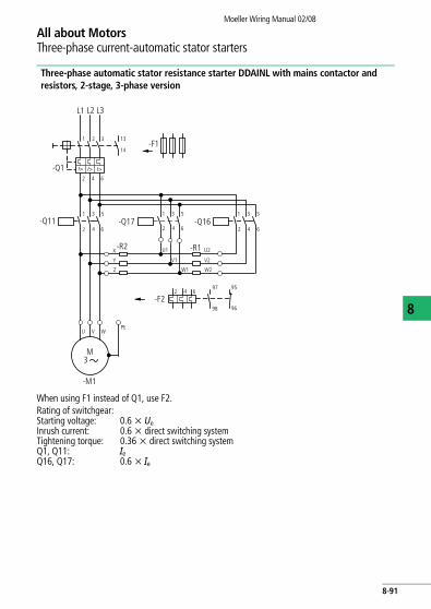
Moeller Wiring Manual 02/08
All about MotorsThree-phase current-automatic stator starters
8
Three-phase automatic stator resistance starter DDAINL with mains contactor and resistors, 2-stage, 3-phase version
When using F1 instead of Q1, use F2.
L1 L2 L3
-Q1
1 2 3
I> I> I>
2 4 6
13
14-F1
1 53
2 4 6-Q11 -Q17
-R2X
Y
Z
-F2
PEU V W
M3
-M1
1 53
2 4 6-Q16
2 4 6
1 3 5
-R1U1 U2
V2
W2
V1
W1
42 6
97 95
98 96
Rating of switchgear:Starting voltage: 0.6 x UeInrush current: 0.6 x direct switching systemTightening torque: 0.36 x direct switching systemQ1, Q11: IeQ16, Q17: 0.6 x Ie
8-91

All about MotorsThree-phase current-automatic stator starters
Moeller Wiring Manual 02/08
8
DDAINL three-phase automatic stator resistance starter with mains contactor and resistors, 2-stage, 3-phase version
Q16: Step contactorK1: Timing relayQ17: Step contactor
K2: Timing relayQ11: Mains contactor
Two-wire control
Always set overload relay to manual reset
-Q1-F2
L1(-Q11)
N
-F0
13
14
95
96
021
22-S11
I 13
14
21
22
-Q11
-Q16A1
A2-K1
A1
A2-Q17
A1
A2
-K115
18
-K2
-Q17
A1
A2-Q11
A1
A2
-K213
14
13
14
-Q16
13
14
15
18
-Q11
32
31-Q11
-F0
-Q113
14
-S12
-Q1132
31-Q11
L1(Q11/1)
22
21
8-92

All about MotorsThree-phase current-automatic stator starters
Moeller Wiring Manual 02/08
8
FunctionPushbutton I energizes step contactor Q16 and timing relay K1. Q16/14-13 – self-maintaining through Q11, Q11/32-31 and pushbutton 0. The motor is connected to the supply with rotor resistors R1 + R2. When the set starting time has elapsed, normally open contact K1/15-18 energizes Q17. Step contactor Q17 bypasses the starting stage R1. At the same time, normally open contact Q17/14-13 energizes K2. When the set starting time has elapsed, K2/15-18 energizes mains contactor Q11. This bypasses the second starting stage R2, and the motor runs at the rated speed. Q11 maintains itself via
Q11/14-13. Q16, Q17, K1 and K2 are de-energized by normally closed contacts Q11/22-21 and Q11/32-31. The motor is switched off with pushbutton 0. In the event of an overload, normally closed contact 95-96 of the overload relay F2 or normally open contact 13-14 of the motor-protective circuit-breaker switch off the motor.
Step contactor Q17, resistor R2 and timing relay K1 are omitted in single-stage starting circuits. Timing relay K2 is connected directly to Q16/13 and resistor R2 is connected by means of its terminals U1, V1 and W1 to Q11/2, 4, 6.
Three-wire controlDouble actuatorI = ON0 = OFF
Two-wire control
-S11
Q1132
2221
Q1121
F296
2221
1413 1413
0 I
A B
F296
Q1122
Q1132
-S12
8-93

All about MotorsThree-phase current-automatic stator starters
Moeller Wiring Manual 02/08
8
Three-phase automatic stator resistance starter ATAINL with mains contactor and starting transformer, 1-stage, 3-phase
When using F1 instead of Q1, use F2. Rating of switchgear
L1 L2 L3
4
1 53
2 4 6
U V W
1 53
2 4 6
a
U2 V2 W2
1U1
2W1
2V1
2U1
1V1
1W1
M3
M1
F1
2 6
1 53
Q113
14
Q111 53
2 4 6K1
Q13
2 4 6 97 95
98 96
I > I > I >
Starting voltage = 0.7 x Ue (typical value) Tightening torque
= 0.49 x direct switching system
Inrush current = 0.49 x direct switching system
Q1, Q11 = Ie
IA/Ie = 6 Q16 = 0.6 x Ie
tA = 10 s Q13 = 0.25 x Ie
Ops/h = 30
8-94

All about MotorsThree-phase current-automatic stator starters
Moeller Wiring Manual 02/08
8
FunctionPressing pushbutton I simultaneously energizes star contactor Q13, timing relay K1 and, via normally open contact Q13/13–14, step contactor Q16, and are maintained via K1/13-14. When K1 has elapsed, normally closed contact K1/55–56 de-energizes star contactor Q13, and – via normally open contact Q13/13–14 – Q16 de-energizes: The starting transformer is disconnected, and the motor runs at the rated speed.
The motor cannot start up again unless previously switched off by actuation of pushbutton 0, or in the event of an overload, by normally closed contact 95–96 of the overload relay F2. With two-wire control, overload relay F2 must always be set to manual reset. If the motor has been switched off by F2, the motor cannot start up again unless the manual reset is released.
Two-wire control
Always set overload relay to manual reset (automatic reset)
Q16: Step contactorK1: Timing relayQ11: Mains contactorQ13: Star contactor
Three-wire controlI: ON0: OFF
Two-wire control
L1
Q1
F0
13
14
95
96F2
21
S110
I13
14K1
13
14
13
14
Q13
Q16
N
A1
A2K1
Q13
A1
A2Q11
K1
A1
A2
K1
Q11
Q13
22
21A1
A2
22
21
67
68
55
56
22
L1(Q11/1)
-F0
95
96-F2
-S12
-K1 -K155
96
67
68
-S11
K113
2221
F296
2221
1413 1413
0 I
A B
K114
-S12
F296
K155
8-95
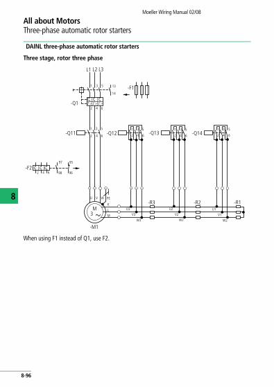
Moeller Wiring Manual 02/08
8
All about MotorsThree-phase automatic rotor starters
DAINL three-phase automatic rotor starters
Three stage, rotor three phase
When using F1 instead of Q1, use F2.
L1 L2 L3
-Q1
1 3 5
I > I > I >
13
14-F1
2 64
2 4 6
PEU V W
M3
-M1
-Q12
2 4 6
97 95
98 96
1 3 5-Q11
-F2
2 4 6
1 3 5 1 53
2 4 6-Q13 -Q142 4 6
1 3 5
K
L
M
U3
V3
W3
U2
V2
W2
-R3 -R2U1
V1
W2
-R1
8-96
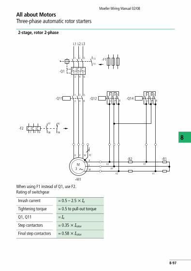
All about MotorsThree-phase automatic rotor starters
Moeller Wiring Manual 02/08
8
2-stage, rotor 2-phase
When using F1 instead of Q1, use F2.Rating of switchgear
L1 L2 L3
1 3 5 13
14
I> I> I>
2 64
1 3 5
2 4 6
PEU V W
M3
-M1
-Q111 3 5
-F2
2 4 6
-R2U1
V1
-R1
-Q1
-F1
97 95
98 96
K
L
M
-Q12 -Q142 4 6
1 3 5
U2
XY
V2
2 4 6
Inrush current = 0.5 – 2.5 x Ie
Tightening torque = 0.5 to pull-out torque
Q1, Q11 = Ie
Step contactors = 0.35 x Irotor
Final step contactors = 0.58 x Irotor
8-97
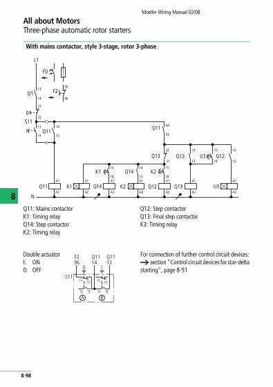
All about MotorsThree-phase automatic rotor starters
Moeller Wiring Manual 02/08
8
With mains contactor, style 3-stage, rotor 3-phase
Q11: Mains contactorK1: Timing relayQ14: Step contactorK2: Timing relay
Q12: Step contactorQ13: Final step contactorK3: Timing relay
Q1 F2
L1
N
F0
0
S11
I
Q11A1
A2
A1
A2
K1
K2
Q14
A1
A2
13
14
13
14
95
96
21
22
13
14Q11
13
14
K1 Q14A1
A2
15
18K2
Q12
14
13A1
A2
15
18A1
A2Q13
Q13 Q1332
31
14
13U3
A1
A2U3
15
18Q12
Q1144
43
Double actuatorI: ON0: OFF
For connection of further control circuit devices: a section "Control circuit devices for star-delta starting", page 8-51
F296
Q1114
Q1113
0 I
-S11
21 22 21 22
13 14 13 14
A B
8-98

All about MotorsThree-phase automatic rotor starters
Moeller Wiring Manual 02/08
8
FunctionPushbutton I energizes mains contactor Q11: normally open contact Q11/14–13 transfers the voltage, Q11/44–43 energizes timing relay K1. The motor is connected to the supply with rotor resistors R1 + R2 + R3 in series. When the set starting time has elapsed, normally open contact K1/15–18 energizes step contactor Q14, which short-circuits starting stage R1 and via Q14/14–13 energizes timing relay K2. When the set starting time has elapsed, K2/15–18 energizes step contactor Q12, which short-circuits starting stage R2 and via Q12/14–13 energizes timing relay K3. When the set starting time has elapsed, K3/15–18 energizes final step contactor Q13, which is maintained via Q13/14–13. Step contactors Q14 and Q12 as well as timing relays K1, K2 and K3 are de-energized via Q13. Final step contactor
Q13 short-circuits the rotor slip rings: the motor operates at the rated speed.
The motor is switched off either by pushbutton 0, or in the event of an overload, by normally closed contact 95–96 of the overload relay F2 or normally open contact 13–14 of the motor-protective circuit-breaker or circuit-breaker.
Step contactor Q13 and Q12 with their resistors R3, R2 and timing relays K3, K2 are omitted in single-stage or two-stage starting circuits. The rotor is then connected to the resistance terminals U, V, W2 or U, V, W1. The references for step contactors and timing relays in the wiring diagrams are then changed from Q13, Q12 to Q12, Q11 or to Q13, Q11 as appropriate.
When there are more than three stages, the additional step contactors, timing relays and resistors have appropriate increasing designations.
8-99
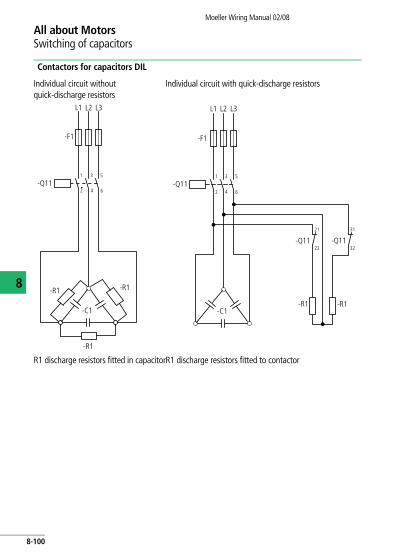
Moeller Wiring Manual 02/08
8
All about MotorsSwitching of capacitors
Contactors for capacitors DIL
Individual circuit without quick-discharge resistors
Individual circuit with quick-discharge resistors
R1 discharge resistors fitted in capacitorR1 discharge resistors fitted to contactor
L3
-F1
1 3 5
2 4 6-Q11
-R1
-C1
-R1
-R1
L1 L2 L3
-F1
1 3 5
2 4 6-Q11
-R1-C1
-R1
L1 L2
21
22-Q11 -Q11
31
32
8-100
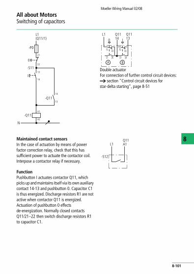
All about MotorsSwitching of capacitors
Moeller Wiring Manual 02/08
8
Double actuatorFor connection of further control circuit devices: a section "Control circuit devices for star-delta starting", page 8-51
L1(Q11/1)
-F0
21
22
-S11
0
I13
14
13
14
-Q11
-Q11A1
A2
N
22
L1
21
0 IQ1114
A B
Q1113
1413
2221
1413
Maintained contact sensorsIn the case of actuation by means of power factor correction relay, check that this has sufficient power to actuate the contactor coil. Interpose a contactor relay if necessary.
FunctionPushbutton I actuates contactor Q11, which picks up and maintains itself via its own auxiliary contact 14-13 and pushbutton 0. Capacitor C1 is thus energized. Discharge resistors R1 are not active when contactor Q11 is energized. Actuation of pushbutton 0 effects de-energization. Normally closed contacts Q11/21–22 then switch discharge resistors R1 to capacitor C1.
L1
-S12
Q11A1
8-101

All about MotorsSwitching of capacitors
Moeller Wiring Manual 02/08
8
Capacitor contactor combination
Capacitor contactor with pilot contactor and series resistors. Individual and parallel circuit
with and without discharge resistors and with series resistors.
On the version without discharge resistors, resistors R1 and the connections to the auxiliary contacts 21–22 and 31–32 are omitted.
L3L1 L2
-F1
1 3 5
2 4 6-Q14
-R1
-C1
-R1
21
22
-Q1131
32
43
44
13
14
21
22
A1
A2
31
32
43
44
1 3 5
2 4 6
A1
A2
13
14
-R2
8-102

All about MotorsSwitching of capacitors
Moeller Wiring Manual 02/08
8
FunctionActuation by two-way pushbutton S11. Pushbutton I energizes pilot contactor Q14, which switches capacitor C1 in with bridged series resistors R2. Normally open contact Q14/14-13 energizes mains contactor Q11. Capacitor C1 is then switched in with bridged series resistors R2. Q14 is maintained via Q11/14-13 when Q11 has closed.
Discharge resistors R1 are not operative when Q11 and Q14 are energized. Pushbutton 0 effects de-energization. Normally closed contacts Q11/21–22 and 31–32 then switch discharge resistors R1 to capacitor C1.
Q11: Mains contactorQ14: Pilot contactorActuation by two-way pushbutton S11 Actuation by selector switch S13, two-wire
control S12 (power factor correction relay) and two-way pushbutton S11
-F0
0
I
-S11
L1(Q11/1)
-Q14
21
22
-Q11A1
A2
13
14 -Q1113
14
13
14
-Q14A1
A2
N
-F0
0
I
-S12
L1(Q11/1)
-Q14
21
22
13
14-Q11
13
14
13
14
A1
A2
-S12
-Q14A1
A2-Q11
N
T0 (3)-1-15431
1
234
1
0 2
8-103

Moeller Wiring Manual 02/08
8
All about MotorsDuplex pump control
Fully automatic control with two pumps
Starting sequence of pumps 1 and 2 can be selected by control switch S12
Control circuit wiring with two float switches for basic and peak loads (operation is also possible with two pressure switches)
P1 Auto = Pump 1 constant load, Pump 2 peak load
P2 Auto = Pump 2 constant load, Pump 1 peak load
P1 + P2 = Direct operation independent of float switches (or pressure switches)
a Cable with float, counterweight, pulleys and clamps
b Storage tankc Inlet d Pressure pipee Outlet
f Centrifugal or reciprocating pumpg Pump 1h Pump 2i Suction pipe with filterj Well
L1 L2 L3
-Q1
-F22
-Q11
U V W
M3
-M1
-M2 M3
F7-F11 -F21
-F12
-Q12
U V W
F8
b
d
F7 Q
Q
a
a
F8
c
e
f
f
i
h
g
0
0
I
I
F7: 0
F7: IF8: 0
F8: I
j
I > I > I >
8-104

All about MotorsDuplex pump control
Moeller Wiring Manual 02/08
8
Floa
t sw
itch
F7 c
lose
s bef
ore
F8Q1
1:Pu
mp
1 m
ains
con
tact
orQ
12:P
ump
2 m
ains
con
tact
or
Func
tion
The
dupl
ex p
ump
cont
rol i
s des
igne
d fo
r ope
ratio
n of
tw
o pu
mp
mot
ors M
1 an
d M
2. C
ontro
l is v
ia fl
oat
switc
hes F
7 an
d F8
.O
pera
ting
mod
e se
lect
or sw
itch
S12
in p
ositi
on P
1 au
to:
The
syst
em o
pera
tes a
s fol
low
s:W
hen
the
wat
er le
vel in
the s
tora
ge ta
nk fa
lls o
r rise
s, F7
sw
itche
s pum
p 1
on o
r off
(bas
ic lo
ad).
If th
e w
ater
leve
l dr
ops b
elow
the
rang
e of
F7 (d
ischa
rge
is gr
eate
r tha
n in
take
), F8
star
ts p
ump
2 (p
eak
load
). W
hen
the
wat
er
leve
l rise
s aga
in, F
8 is
deac
tivat
ed. P
ump
2 co
ntin
ues r
unni
ng u
ntil
F7 st
ops b
oth
pum
ps.
The
oper
atin
g se
quen
ce o
f pum
ps 1
and
2 ca
n be
de
term
ined
usin
g op
erat
ing
mod
e se
lect
or sw
itch
S12:
Pos
ition
P1
auto
or P
2 au
to.
In p
ositi
on P
1 +
P2, b
oth
pum
ps a
re in
ope
ratio
n,
inde
pend
ent o
f the
floa
t sw
itche
s (Ca
utio
n! Ta
nk m
ay
poss
ibly
over
flow
).O
n th
e ver
sion
of d
uple
x pum
p co
ntro
l with
aut
omat
ic lo
ad sh
arin
g (T
0(3)
-4-1
5915
), S1
2 ha
s a fu
rther
po
sitio
n: th
e se
quen
ce o
f ope
ratio
ns is
aut
omat
ically
re
vers
ed a
fter e
ach
cycle
.
F11
F0
-F12
-F22
95 96
95 96-F
7Q
2 1-S
1114 13
-F8
Q-S
212 1
14 13-Q
1214 13
-Q11
14 13
NEO
-Q11
A1 A2-Q
12A1 A2
-S12
L 1 2 3 4 5 6 7 8 9 10 11 12
13
0
P 1, P 2
P 1 AutoP 2 Auto
T0(3
)-4-1
5833
8-105

Moeller Wiring Manual 02/08
8
All about MotorsFully automatic pump control
With pressure switch for air tank and domestic water supply without water failure (run dry) safety device
With 3-pole pressure switch MCSN (main circuit)
F1: Fuses (if required)Q1: Motor-protective switch, manual (z. B. PKZ)F7: Pressure switch MCSN, 3-poleM1:Pump motora Air or pressure tankb Non-return valvec Pressure piped Centrifugal (or reciprocating) pumpe Suction pipe with filterf Well
L1L2L3
-F1
-Q1
a
bd
c e
f
U V W
-M1
M3
P-F7
I > I >I >
8-106
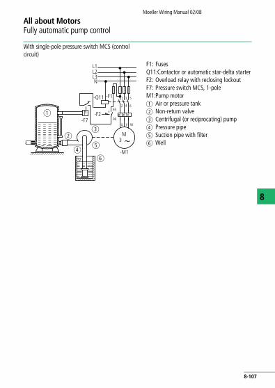
All about MotorsFully automatic pump control
Moeller Wiring Manual 02/08
8
With single-pole pressure switch MCS (control circuit)
F1: FusesQ11:Contactor or automatic star-delta starterF2: Overload relay with reclosing lockoutF7: Pressure switch MCS, 1-poleM1:Pump motora Air or pressure tankb Non-return valvec Centrifugal (or reciprocating) pumpd Pressure pipee Suction pipe with filterf Well
3 5
2 4 695
96
-M1
M3
U V W
L1L2L3
-F1
-F2a
bc
de
f
P
N
-Q11 1
-F7
8-107

All about MotorsFully automatic pump control
Moeller Wiring Manual 02/08
8
With 3-pole float switch SW (main circuit)
F1: Fuses (if required)Q1: Motor-protective circuit-breakers,
manual (z. B. PKZ)F7: Float switch 3-pole (circuit: pump full)M1:Pump motorHW:Highest levelNW:Lowest valuea Cable with float, counterweight,
pulleys and clampsb Storage tankc Pressure piped Centrifugal (or reciprocating) pumpe Outlet f Suction pipe with filterg Well
U V W
L1L2L3
-F1
-F7
I
0
HW
NW-Q1
-M1
Q
M3
a
c
b
de
f
g
I > I >I >
8-108
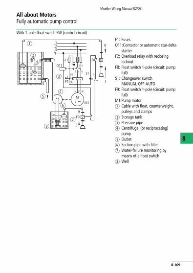
All about MotorsFully automatic pump control
Moeller Wiring Manual 02/08
8
With 1-pole float switch SW (control circuit)
F1: Fuses Q11:Contactor or automatic star-delta
starterF2: Overload relay with reclosing
lockoutF8: Float switch 1-pole (circuit: pump
full)S1: Changeover switch
MANUAL-OFF-AUTOF9: Float switch 1-pole (circuit: pump
full)M1:Pump motora Cable with float, counterweight,
pulleys and clampsb Storage tankc Pressure piped Centrifugal (or reciprocating)
pumpe Outlet f Suction pipe with filterg Water-failure monitoring by
means of a float switchh Well
L1
U V W
L2L3N
-F1
-F2
-Q11 1 3 5
2 4 695
96
-F8
0
H A
-M1
S1
HW
NW
M3
-F9
I
0
Q
Q
a
b
c
de
h
f
g
0
I
8-109

Moeller Wiring Manual 02/08
8
All about MotorsOff position interlock of the loads
Solution using NZM circuit-breakers
Off position interlock for control switches (Hamburg circuit) with auxiliary contact VHI (S3)
and undervoltage release. Cannot be used with motor operator.
-S3
-R1 -R2
51 52
U <
-Q1
I > I > I >
I > I > I >-Q2I > I > I >-Q3 I > I > I >-Q4
8-110

Moeller Wiring Manual 02/08
All about MotorsFully automatic main transfer switch with automatic reset
8
Off position interlock for control or master switches by means of auxiliary contacts VHI (S3),
NHI (S1) and undervoltage release. Cannot be used with motor operator.
a Emergency-Stopb Off position interlock contacts
on the control or master switches
-S3
a
V
95
96
U <
-Q1-S1
51
52
1011
1011
1011
b
b
b
I > I > I >
8-111
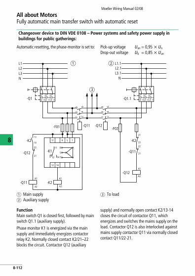
All about MotorsFully automatic main transfer switch with automatic reset
Moeller Wiring Manual 02/08
8
Changeover device to DIN VDE 0108 – Power systems and safety power supply in buildings for public gatherings:
Automatic resetting, the phase-monitor is set to: Pick-up voltage Uan = 0,95 x Un Drop-out voltage Ub = 0,85 x Uan
FunctionMain switch Q1 is closed first, followed by main switch Q1.1 (auxiliary supply).
Phase monitor K1 is energized via the main supply and immediately energizes contactor relay K2. Normally closed contact K2/21–22 blocks the circuit. Contactor Q12 (auxiliary
supply) and normally open contact K2/13-14 closes the circuit of contactor Q11, which energizes and switches the mains supply on the load. Contactor Q12 is also interlocked against mains supply contactor Q11 via normally closed contact Q11/22-21.
a Main supplyb Auxiliary supply
c To load
L1L2L3N
-Q1
-F01
21
22
14
21
21
22
2211
11
12 14
12 14
R
R S
S
T
T
-F02
5 6
3 4
1 2
5 6
3 4
1 2
-Q1.1
-Q11
-K2
-Q12
-Q12
-Q11
-K2
-Q12
-Q11 -K2
-K1
A1
A2
A1
A2
A1
A2
L2.1L3.1
N
L1.1
13
a b
c
I > I > I >I > I > I >
8-112