Embed Size (px)
Citation preview

User Guide
XPA Ultra Series:
Audio Products
Half-Rack Audio Power Amplifiers
68-3149-01 Rev. B01 19
XPA U 358, XPA U 358-70V, XPA U 358-100V, XPA U 358C-70V, XPA U 358C-100V
XPA U 1004, XPA U 1004-70V, XPA U 1004-100V, XPA U 1004C-70V, XPA U 1004C-100V
XPA U 1002, XPA U 1002-70V, XPA U 1002-100V

Safety InstructionsSafety Instructions • English
WARNING: This symbol, , when used on the product, is intended to alert the user of the presence of uninsulated dangerous voltage within the product’s enclosure that may present a risk of electric shock.
ATTENTION: This symbol, , when used on the product, is intended to alert the user of important operating and maintenance (servicing) instructions in the literature provided with the equipment.
For information on safety guidelines, regulatory compliances, EMI/EMF compatibility, accessibility, and related topics, see the Extron Safety and Regulatory Compliance Guide, part number 68-290-01, on the Extron website, www.extron.com.
Sicherheitsanweisungen • Deutsch
WARNUNG: Dieses Symbol auf dem Produkt soll den Benutzer darauf aufmerksam machen, dass im Inneren des Gehäuses dieses Produktes gefährliche Spannungen herrschen, die nicht isoliert sind und die einen elektrischen Schlag verursachen können.
VORSICHT: Dieses Symbol auf dem Produkt soll dem Benutzer in der im Lieferumfang enthaltenen Dokumentation besonders wichtige Hinweise zur Bedienung und Wartung (Instandhaltung) geben.
Weitere Informationen über die Sicherheitsrichtlinien, Produkthandhabung, EMI/EMF-Kompatibilität, Zugänglichkeit und verwandte Themen finden Sie in den Extron-Richtlinien für Sicherheit und Handhabung (Artikelnummer 68-290-01) auf der Extron-Website, www.extron.com.
Instrucciones de seguridad • Español
ADVERTENCIA: Este símbolo, , cuando se utiliza en el producto, avisa al usuario de la presencia de voltaje peligroso sin aislar dentro del producto, lo que puede representar un riesgo de descarga eléctrica.
ATENCIÓN: Este símbolo, , cuando se utiliza en el producto, avisa al usuario de la presencia de importantes instrucciones de uso y mantenimiento recogidas en la documentación proporcionada con el equipo.
Para obtener información sobre directrices de seguridad, cumplimiento de normativas, compatibilidad electromagnética, accesibilidad y temas relacionados, consulte la Guía de cumplimiento de normativas y seguridad de Extron, referencia 68-290-01, en el sitio Web de Extron, www.extron.com.
Instructions de sécurité • Français
AVERTISSEMENT : Ce pictogramme, , lorsqu’il est utilisé sur le produit, signale à l’utilisateur la présence à l’intérieur du boîtier du produit d’une tension électrique dangereuse susceptible de provoquer un choc électrique.
ATTENTION : Ce pictogramme, , lorsqu’il est utilisé sur le produit, signale à l’utilisateur des instructions d’utilisation ou de maintenance importantes qui se trouvent dans la documentation fournie avec le matériel.
Pour en savoir plus sur les règles de sécurité, la conformité à la réglementation, la compatibilité EMI/EMF, l’accessibilité, et autres sujets connexes, lisez les informations de sécurité et de conformité Extron, réf. 68-290-01, sur le site Extron, www.extron.com.
Istruzioni di sicurezza • Italiano
AVVERTENZA: Il simbolo, , se usato sul prodotto, serve ad avvertire l’utente della presenza di tensione non isolata pericolosa all’interno del contenitore del prodotto che può costituire un rischio di scosse elettriche.
ATTENTZIONE: Il simbolo, , se usato sul prodotto, serve ad avvertire l’utente della presenza di importanti istruzioni di funzionamento e manutenzione nella documentazione fornita con l’apparecchio.
Per informazioni su parametri di sicurezza, conformità alle normative, compatibilità EMI/EMF, accessibilità e argomenti simili, fare riferimento alla Guida alla conformità normativa e di sicurezza di Extron, cod. articolo 68-290-01, sul sito web di Extron, www.extron.com.
Instrukcje bezpieczeństwa • Polska
OSTRZEŻENIE: Ten symbol, , gdy używany na produkt, ma na celu poinformować użytkownika o obecności izolowanego i niebezpiecznego napięcia wewnątrz obudowy produktu, który może stanowić zagrożenie porażenia prądem elektrycznym.
UWAGI: Ten symbol, , gdy używany na produkt, jest przeznaczony do ostrzegania użytkownika ważne operacyjne oraz instrukcje konserwacji (obsługi) w literaturze, wyposażone w sprzęt.
Informacji na temat wytycznych w sprawie bezpieczeństwa, regulacji wzajemnej zgodności, zgodność EMI/EMF, dostępności i Tematy pokrewne, zobacz Extron bezpieczeństwa i regulacyjnego zgodności przewodnik, część numer 68-290-01, na stronie internetowej Extron, www.extron.com.
Инструкция по технике безопасности • Русский
ПРЕДУПРЕЖДЕНИЕ: Данный символ, , если указан на продукте, предупреждает пользователя о наличии неизолированного опасного напряжения внутри корпуса продукта, которое может привести к поражению электрическим током.
ВНИМАНИЕ: Данный символ, , если указан на продукте, предупреждает пользователя о наличии важных инструкций по эксплуатации и обслуживанию в руководстве, прилагаемом к данному оборудованию.
Для получения информации о правилах техники безопасности, соблюдении нормативных требований, электромагнитной совместимости (ЭМП/ЭДС), возможности доступа и других вопросах см. руководство по безопасности и соблюдению нормативных требований Extron на сайте Extron: , www.extron.com, номер по каталогу - 68-290-01.
安全说明 • 简体中文
警告: 产品上的这个标志意在警告用户该产品机壳内有暴露的危险 电压,有触电危险。
注意: 产品上的这个标志意在 提示用户设备随附的用户手册中有 重要的操作和维护(维修)说明。
关于我们产品的安全指南、遵循的规范、EMI/EMF 的兼容性、无障碍 使用的特性等相关内容,敬请访问 Extron 网站 , www.extron.com,参见
Extron 安全规范指南,产品编号 68-290-01。

안전 지침 • 한국어
경고: 이 기호 가 제품에 사용될 경우, 제품의 인클로저 내에 있는 접지되지 않은 위험한 전류로 인해 사용자가 감전될 위험이 있음을 경고합니다.
주의: 이 기호 가 제품에 사용될 경우, 장비와 함께 제공된 책자에 나와 있는 주요 운영 및 유지보수(정비) 지침을 경고합니다.
안전 가이드라인, 규제 준수, EMI/EMF 호환성, 접근성, 그리고 관련 항목에 대한 자세한 내용은 Extron 웹 사이트(www.extron.com)의 Extron 안전 및 규제 준수 안내서, 68-290-01 조항을 참조하십시오.
安全記事 • 繁體中文
警告: 若產品上使用此符號,是為了提醒使用者,產品機殼內存在著 可能會導致觸電之風險的未絕緣危險電壓。
注意 若產品上使用此符號,是為了提醒使用者,設備隨附的用戶手冊中有重要的操作和維護(維修)説明。
有關安全性指導方針、法規遵守、EMI/EMF 相容性、存取範圍和相關主題的詳細資訊,請瀏覽 Extron 網站:www.extron.com,然後參閱《Extron 安全性與法規遵守手冊》,準則編號 68-290-01。
安全上のご注意 • 日本語
警告: この記号 が製品上に表示されている場合は、筐体内に絶縁されて いない高電圧が流れ、感電の危険があることを示しています。
注意:この記号 が製品上に表示されている場合は、本機の取扱説明書に 記載されている重要な操作と保守(整備)の指示についてユーザーの注意を喚起するものです。
安全上のご注意、法規厳守、EMI/EMF適合性、その他の関連項目に ついては、エクストロンのウェブサイト www.extron.com より 『Extron Safety and Regulatory Compliance Guide』 (P/N 68-290-01) をご覧ください。
Copyright© 2018-2019 Extron Electronics. All rights reserved. www.extron.com
TrademarksAll trademarks mentioned in this guide are the properties of their respective owners.The following registered trademarks (®), registered service marks (SM), and trademarks (TM) are the property of RGB Systems, Inc. or Extron Electronics (see the current list of trademarks on the Terms of Use page at www.extron.com):
Registered Trademarks (®)
Extron, Cable Cubby, ControlScript, CrossPoint, DTP, eBUS, EDID Manager, EDID Minder, Flat Field, FlexOS, Glitch Free. Global Configurator, Global Scripter, GlobalViewer, Hideaway, HyperLane, IP Intercom, IP Link, Key Minder, LinkLicense, LockIt, MediaLink, MediaPort, NetPA, PlenumVault, PoleVault, PowerCage, PURE3, Quantum, Show Me, SoundField, SpeedMount, SpeedSwitch, StudioStation, System INTEGRATOR, TeamWork, TouchLink, V-Lock, VideoLounge, VN-Matrix, VoiceLift, WallVault, WindoWall, XTP, XTP Systems, and ZipClip
Registered Service Mark(SM) : S3 Service Support Solutions
Trademarks (™)
AAP, AFL (Accu-Rate Frame Lock), ADSP (Advanced Digital Sync Processing), Auto-Image, AVEdge, CableCover, CDRS (Class D Ripple Suppression), Codec Connect, DDSP (Digital Display Sync Processing), DMI (Dynamic Motion Interpolation), Driver Configurator, DSP Configurator, DSVP (Digital Sync Validation Processing), eLink, EQIP, Everlast, FastBite, FOX, FOXBOX, IP Intercom HelpDesk, MAAP, MicroDigital, Opti-Torque, PendantConnect, ProDSP, QS-FPC (QuickSwitch Front Panel Controller), Room Agent, Scope-Trigger, ShareLink, SIS, Simple Instruction Set, Skew-Free, SpeedNav, Triple-Action Switching, True4K, Vector™ 4K , WebShare, XTRA, and ZipCaddy

FCC Class B Notice
NOTE: This device complies with part 15 of the FCC rules. Operation is subject to the following two conditions: (1) This device may not cause harmful interference, and (2) This device must accept any interference received, including interference that may cause undesired operation.
This equipment has been tested and found to comply with the limits for a Class B digital device, pursuant to part 15 of the FCC rules. These limits provide reasonable protection against harmful interference in a residential installation. This equipment generates, uses, and can radiate radio frequency energy and, if not installed and used in accordance with the instructions, may cause harmful interference to radio communications. There is no guarantee that interference will not occur. If this equipment does cause interference to radio or television reception, which can be determined by turning the equipment off and on, you are encouraged to try to correct the interference by one or more of the following measures:
• Reorient or relocate the receiving antenna.
• Increase the separation between the equipment and receiver.
• Connect the equipment into an outlet on a circuit different from that to which the receiver is connected.
• Consult the dealer or an experienced radio/TV technician for help.
In order to maintain compliance with FCC regulations, shielded cables must be used with this equipment. Operation with non-approved equipment or unshielded cables is likely to result in interference to radio and TV reception. The user is cautioned that changes and modifications made to the equipment without the approval of the manufacturer could void the user’s authority to operate this equipment.
NOTE: For more information on safety guidelines, regulatory compliances, EMI/EMF compatibility, accessibility, and related topics see the Extron Safety and Regulatory Compliance Guide on the Extron website.

Conventions Used in this Guide
NotificationsThe following notifications are used in this guide:
DANGER:
• Will result in serious injury or death.
• Entraînera des blessures graves ou la mort.
WARNING: Potential risk of severe injury or death.
AVERTISSEMENT : Risque potentiel de blessure grave ou de mort.
CAUTION: Risk of minor personal injury.
ATTENTION : Risque de blessure mineure.
ATTENTION:
• Risk of property damage.
• Risque de dommages matériels.
NOTE: A note draws attention to important information.
TIP: A tip provides a suggestion to make working with the application easier.
Specifications AvailabilityProduct specifications are available on the Extron website, www.extron.com.
Extron Glossary of TermsA glossary of terms is available at http://www.extron.com/technology/glossary.aspx.

viXPA Ultra Series Power Amplifiers • Contents
Contents
Introduction ...............................................1About this Manual................................................ 1
Terms Used in this Manual ............................... 1Features .............................................................. 1
Installation .................................................4Application Examples .......................................... 4Mounting the XPA Ultra Series Amplifiers ............. 6
Tabletop Use ................................................... 6UL Guidelines for Rack Mounting ..................... 6Rack Mounting ................................................ 7Rack Mounting Ventilation Recommendations ....................................... 10
Flexible Conduit Adapter Kit Installation ............. 11
Operation .................................................15Front Panel Features and Operation .................. 15Rear Panel Features and Operation ................... 16
Bridged Mono Output (8 ohm/4 ohm outputs only) ................................................. 19
Troubleshooting ................................................. 20Amplifier Fails to Exit Standby Mode Promptly ....................................................... 20
Amplifier Enters Standby Mode Too Early ....... 21Limiter/Protect LED Warning Indicators.......... 21Over Temp Indicator LED ............................... 21

XPA Ultra Series Power Amplifiers • Introduction 1
Introduction
About this ManualThis manual contains information about the Extron XPA Ultra Series of power amplifiers:
• XPA U 358 eight channel low impedance power amplifier
• XPA U 358-70V eight channel 70 volt power amplifier
• XPA U 358-100V eight channel 70 volt power amplifier
• XPA U 358C-70V eight channel combination low impedance and 70 volt power amplifier
• XPA U 358C-100V eight channel combination low impedance and 70 volt power amplifier
• XPA U 1004 four channel low impedance power amplifier
• XPA U 1004-70V four channel 70 volt power amplifier
• XPA U 1004-100V four channel 100 volt power amplifier
• XPA U 1004C-70V four channel combination low impedance and 70 volt power amplifier
• XPA U 1004C-100V four channel combination low impedance and 100 volt power amplifier
• XPA U 1002 two channel low impedance power amplifier
• XPA U 1002-70V two channel 70 volt power amplifier
• XPA U 1002-100V two channel 100 volt power amplifier
Terms Used in this ManualThe terms “amplifier” and “power amplifier” are used interchangeably in this manual to refer to all of the XPA Ultra models.
Features• Output Power
• XPA U 358 models — 35 watts rms output power per channel, all channels driven.
• XPA U 1004 models — 100 watts rms output power per channel, all channels driven.
• XPA U 1002 models — 100 watts rms output power per channel, all channels driven.
• ENERGY STAR® qualified amplifiers — The XPA Ultra Series are ENERGY STAR qualified amplifiers and energy efficient products that conserve energy and reduce costs.

XPA Ultra Series Power Amplifiers • Introduction 2
• Extron Patented CDRS - Class D Ripple Suppression — CDRS is an Extron Patented technology that provides a smooth, clean audio waveform and an improvement in signal fidelity over conventional Class D amplifier designs. CDRS eliminates the high frequency switching ripple characteristics of Class D amplifiers, a source of RF emissions which can interfere with sensitive AV equipment such as wireless microphones.
• Convection cooled, fanless operation - can be stacked without extra rack space for ventilation — The XPA Ultra Series amplifiers do not require internal fans or vents for cooling, ensuring quiet, reliable operation. They generate substantially less heat than conventional power amplifiers, making them ideal for rack-mount applications where space is at a premium.
• Eight channels (XPA U 358 models), four channels (XPA U 1004 models), or two channels (XPA U 1002 models) in a 1U, half rack width enclosure - single and dual rack mount hardware included — The channel density of the XPA Ultra Series amplifiers reduce rack space requirements for many installations. The included single and side by side rack mount hardware simplifies planning and saves cost.
• Defeatable auto-standby with fast wake up — The XPA Ultra Series amplifiers meet ENERGY STAR qualification requirements with an auto-standby feature that automatically places the amplifier into standby after 25 minutes of inactivity, dramatically reducing power consumption. The XPA Ultra Series amplifiers quickly return to full power status in less than 100 ms upon signal detection, with minimal inrush current. Auto-standby can be disabled if required.
• UL 2043 plenum rated when used with optional Flexible Conduit Adapter Kit — The XPA Ultra Series amplifiers meet UL 2043 for smoke and heat release for installation within a plenum airspace above a drop ceiling when used with the optional Flexible Conduit Adapter Kit. Above-the-ceiling placement conceals the amplifier to prevent theft, and is convenient for installing equipment when space inside the room is limited.
• Professional grade signal-to-noise and THD+N performance — The XPA Ultra Series amplifiers deliver professional grade performance, featuring 100 dB signal-to-noise ratio and THD+N of less than 0.1%.
• Ultra low inrush current at power up - no need for power sequencing — Allows multiple XPA Ultra Series amplifiers to be powered on simultaneously without overloading power circuits. This eliminates the need for power sequencing.
• Power factor correction - removes harmonic content on AC line — The XPA Ultra Series amplifiers feature power factor correction technology that smooths out the high peak currents of the amplifiers’ current draw, minimizing the presence of high frequency harmonics on the AC power line, preventing audible artifacts from being transmitted to other audio equipment in the system.
• Rear panel recessed, detented level controls — Provides attenuation of input signals for adjusting audio system gain staging. These controls are located on the rear panel to prevent tampering with level adjustments. Laser etched markings provide enhanced visibility of settings for ease of configuration.
• Automatic clip limiter — Detects actual onset of clipping. Gain is automatically reduced without audible artifacts to protect speakers from clipping distortion.
• Multiple protection circuits — Active during output shorts, thermal overload, or DC faults to prevent damage to the amplifier and speakers.
• Remote standby port — Enables the XPA Ultra Series amplifiers to be remotely powered down when not in use, reducing operating cost.

XPA Ultra Series Power Amplifiers • Introduction 3
• High pass filter for high impedance models — This selectable filter, available on the XPA Ultra Series high impedance models, rolls off frequencies below 80 Hz to prevent saturation of speaker transformers.
• 5 mm screw-lock captive screw speaker connectors — Enable simple, secure connections with 22 to 12 AWG speaker cables.
• Front and rear-mounted signal and protection indication LEDs — Provide convenient indication of input signal presence and protection circuit activation from both sides of an equipment rack.
• Front panel over-temperature LED — Provides visual indication that the amplifier temperature has exceeded the optimal value, well in advance of the onset of thermal protection circuitry.
• Internal Extron Everlast Power Supply — Provides worldwide power compatibility, with high-demonstrated reliability and low power consumption for reduced operating cost.
• Extron Everlast Power Supply is covered by a 7-year parts and labor warranty.

XPA Ultra Series Power Amplifiers • Installation 4
Installation
This section discusses how to install the XPA Ultra Series of audio power amplifiers. Topics covered include:
• Application Examples
• Mounting the XPA Ultra Series Amplifiers
• Flexible Conduit Adapter Kit Installation
Application ExamplesThe following illustrations are application examples for the XPA Ultra Series power amplifiers.
Audio Audio
Ethernet
Audio
Display
DMP EXP
CATx Cable up to 230' (70 m)
HDMI
Ethernet
Ethernet
Ethernet
RS-232
ExtronDMP 128 Plus C V ATDigital Matrix Processor
ExtronDTP HDMI 4K 230 RxReceiver
ExtronDTP CrossPoint 82 4K IPCP SAScaling Presentation Matrix Switcher
CONFIG
DTP CROSSPOINT 4K SERIESDIGITAL PRESENTATION SWITCHER
CONTROL I/O
AUDIOVIDEO
LOGO
SELECT ENTER PRESET VIEW ESC1 2 3 4
1 2 3 4
5 6 7 8MIC VOLUME VOLUME
INPUTS
OUTPUTS
eBUS
COM
1 1 2
1 2 23 3 4
1 2
3 4
IR/S I/O RELAYS
S LIMIT
OVER
RTS
CTS
Tx
Rx
HDMI
DIGITAL MATRIX PROCESSOR
CONFIG
CLIPEXP LAN USB SIGNAL
CLIP
SIGNAL
1 2 3 4 5 6 7 8 1 2 3 4 5 6 7 89 10 11 12ACTIVITY
INPUTS OUTPUTS
DMP 128 Plus
•P HU S••P HU S•
•P HU S••P HU S•
•P HU S••P HU S•
•P HU S••P HU S•
Table Microphones
Table Microphones
Audio
ExtronXPA U 358Power Amplifer
ExtronSF 3C LPCeiling Speakers
ExtronTLP Pro 720CCable Cubby TouchLink Pro Touchpanel
Audio Audio
Ethernet/PoEExtron
Help SystemOff
Display
RoomControl
Off
Mute
Screen
Lighting December 15, 2013 - 7:58 AM AudioControl
Volume
Mute
Tuner 1 2 3VCRLaptop PC DVDDocCam
TunerOn
Channel
Last
Presets
MorePresets
321
654
987
Enter0
AV LAN
Conference Room
DTP HDMI 230 Rx
OVER DTP
RS-232 IR
Tx Rx Tx RxG
XPA U 358 SERIES
LIMITER/PROTECT
SIGNAL
8OVERTEMP 7654321
POWER AMPLIFIERS
AV LANLAN
VoIP AV LAN
AV Sources
Figure 1. XPA U 358 Application Example
1 XPA U 358 Application Diagram

XPA Ultra Series Power Amplifiers • Installation 5
Ethernet
Ethernet
AV LAN
Ethernet
LAN
VoIP
ExtronXPA U 358-70VPower Amplifer
ExtronSF 3CT LPCeiling Speaker(Zone A1)
(Zone A3)
(Zone A2)
ExtronTLP Pro 725MTouchLink Pro Touchpanel
DMP EXP
AudioAudio
Ethernet/PoE
Ethernet
Ethernet/PoE
HDMI
ExtronDMP 128 Plus C V ATDigital Matrix Processor
ExtronDTP CrossPoint 84 4K IPCP SAScaling Presentation Matrix Switcher
ExtronSF 3CT LPCeiling Speaker
(Zone A4)
ExtronSF 3CT LPCeiling Speaker
DIGITAL MATRIX PROCESSOR
CONFIG
CLIPEXP LAN USB SIGNAL
CLIP
SIGNAL
1 2 3 4 5 6 7 8 1 2 3 4 5 6 7 89 10 11 12ACTIVITY
INPUTS OUTPUTS
DMP 128 Plus
AV LAN
AV LAN
Room A
AV Sources
Lectern
ExtronSF 3CT LPCeiling Speaker(Zone B1)
(Zone B3)
(Zone B2)
ExtronSF 3CT LPCeiling Speaker
(Zone B4)
ExtronSF 3CT LPCeiling Speaker
AV LAN
Room B
Lectern
CONFIG
DTP CROSSPOINT 4K SERIESDIGITAL PRESENTATION SWITCHER
CONTROL I/O
AUDIOVIDEO
LOGO
SELECT ENTER PRESET VIEW ESC1 2 3 4
1 2 3 4
5 6 7 8MIC VOLUME VOLUME
INPUTS
OUTPUTS
eBUS
COM
1 1 2
1 2 23 3 4
1 2
3 4
IR/S I/O RELAYS
S LIMIT
OVER
RTS
CTS
Tx
Rx
Microphones
mu
tese
lect
audio
menu
select ready
sync
power
mu
tese
lect
audio
menu
select ready
sync
power
Wireless Microphone System
XPA U 358 SERIES
LIMITER/PROTECT
SIGNAL
8OVERTEMP 7654321
POWER AMPLIFIERS
ExtronTLP Pro 725MTouchLink Pro Touchpanel
Figure 2. XPA U 358-70V Application Examples
2 XPA U 358 70V Application Diagram

XPA Ultra Series Power Amplifiers • Installation 6
Mounting the XPA Ultra Series AmplifiersThe XPA Ultra Series amplifiers can be mounted in a rack using included rack ears, set on a table, mounted on a rack shelf, or mounted in the plenum space above a ceiling-mounted projector. Additionally, two XPA Ultra Series amplifiers can be connected using the included bridging plate to create a full rack-width unit.
Tabletop UseFour self-adhesive rubber feet are included with the audio amplifier.
For tabletop use, attach one foot at each corner on the bottom side of the amplifier and place the unit in the desired location.
UL Guidelines for Rack MountingThe following Underwriters Laboratories (UL) guidelines pertain to the installation of the equipment in a rack.
1. Elevated operating ambient — If installed in a closed or multi-unit rack assembly, the operating ambient temperature of the rack environment may be greater than room ambient. Therefore, consider installing the equipment in an environment compatible with the maximum ambient temperature specified by the manufacturer [Tma = +32 to +122 °F (0 to +50 °C)].
2. Reduced air flow — Installation of the equipment in a rack should be such that the amount of air flow required for safe operation of the equipment is not compromised.
3. Mechanical loading — Mounting of the equipment in the rack should be such that a hazardous condition is not achieved due to uneven mechanical loading.
4. Circuit overloading — Consideration should be given to the connection of the equipment to the supply circuit and the effect that overloading of the circuits might have on overcurrent protection and supply wiring. Appropriate consideration of equipment nameplate ratings should be used when addressing this concern.
5. Reliable earthing (grounding) — Reliable earthing of rack-mounted equipment should be maintained. Particular attention should be given to supply connections other than direct connections to the branch circuit (such as the use of power strips).

XPA Ultra Series Power Amplifiers • Installation 7
Rack MountingThe XPA Ultra Series amplifiers can be rack mounted using one of the following methods.
Rack Ear Rack Mounting
The XPA Ultra Series amplifiers ship with a set of rack ears so the half rack-width amplifiers can be installed in a full rack-width space.
Mount the amplifier with the rack ears as follows:
1. If feet were installed on the bottom of the amplifier, remove them.
2. Attach the included rack ears to the sides of the amplifier with the four provided #6 machine screws (see figure 3, 1).
e
XPA U 1004 SERIES
12
34
OVERTEMP
LIMITER/PROTECT
SIGNAL
POWER AMPLIFIERS
1
Figure 3. Install XPA Ultra Rack Ears
3. Insert the amplifier into the rack, align the holes in the rack ears with the holes on the rack.
4. Secure the amplifier to the rack using four provided 10-32 x 3/4” screws (see figure 4, 2).
e
XPA U 1004 SERIES
12
34
OVERTEMP
LIMITER/PROTECT
SIGNAL
POWER AMPLIFIERS
2
Figure 4. Secure XPA Ultra Amplifier to Rack
3 Install XPA Ultra Rack Ears
4 Secure XPA Ultra to Rack
XPA Ultra Series Power Amplifiers • Installation 8
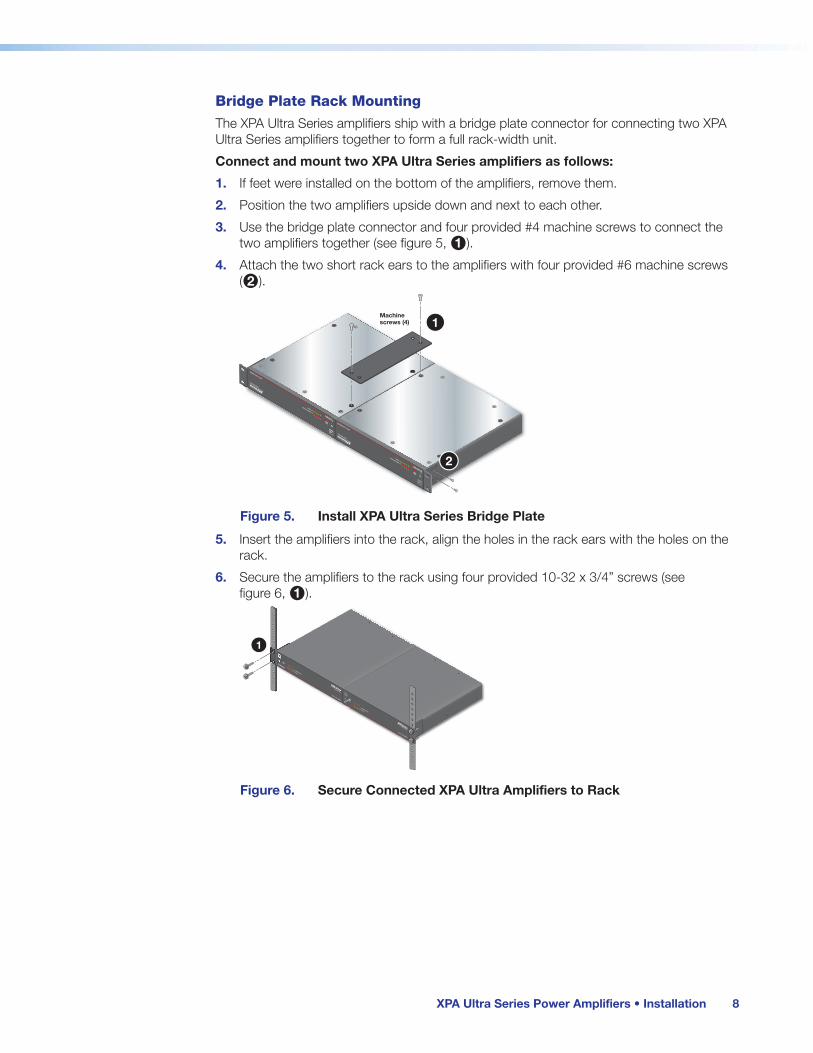
Bridge Plate Rack Mounting
The XPA Ultra Series amplifiers ship with a bridge plate connector for connecting two XPA Ultra Series amplifiers together to form a full rack-width unit.
Connect and mount two XPA Ultra Series amplifiers as follows:
1. If feet were installed on the bottom of the amplifiers, remove them.
2. Position the two amplifiers upside down and next to each other.
3. Use the bridge plate connector and four provided #4 machine screws to connect the two amplifiers together (see figure 5, 1).
4. Attach the two short rack ears to the amplifiers with four provided #6 machine screws (2).
e
XPA U 1004 SERIES
12
34
OVER TEMP
LIMITER/PROTECT
SIGNAL
POWER AMPLIFIERS
e
e
XPA U 1004 SERIES
12
34
OVER TEMP
LIMITER/PROTECT
SIGNAL
POWER AMPLIFIERS
Machinescrews (4)
2
1
Figure 5. Install XPA Ultra Series Bridge Plate
5. Insert the amplifiers into the rack, align the holes in the rack ears with the holes on the rack.
6. Secure the amplifiers to the rack using four provided 10-32 x 3/4” screws (see figure 6, 1).
e
XPA U 1004 SERIES
12
34
OVERTEMP
LIMITER/PROTECT
SIGNAL
POWER AMPLIFIERS
ES
RS
e
XPA U 1004 SERIES
12
34
OVERTEMP
LIMITER/PROTECT
SIGNAL
POWER AMPLIFIERS
1
Figure 6. Secure Connected XPA Ultra Amplifiers to Rack
5 Bridging Plate
6 Secure Connected XPAs to Rack

XPA Ultra Series Power Amplifiers • Installation 9
Rack Shelf Mounting
The XPA Ultra Series can be mounted in a shelf using the optional RSU 129 1U Universal Rack Shelf Kit or the RSB 129 1U Basic Rack Shelf.
Mount the amplifier with the shelf as follows:
1. If feet were installed on the bottom of the amplifier, remove them.
2. Place the amplifier on one half of the rack shelf.
3. Align the front of the amplifier with the front of the shelf, and align the threaded holes on the bottom of the amplifier with the holes in the rack shelf.
4. Attach the amplifier to the rack shelf with the two provided 4-40 x 3/16” machine screws.
ATTENTION:
• Using screws longer than 3/16” will damage the unit and void the warranty.
• L’utilisation de vis plus longues que 3/16” endommagera l’unité et annulera la garantie.
5. Insert the screws from the underside of the shelf, and securely fasten them into diagonally-opposite corners.
(2) 4-40 x 3/16"Screws
RSU 1291U Universal Rack Shelf
False faceplateuses 2 screws.
Use 2 mounting holeson opposite corners.
e
XPA U 1004 SERIES
12
34
OVERTEMP
LIMITER/PROTECT
SIGNAL
POWER AMPLIFIERS
Figure 7. Mounting the Amplifier onto a Rack Shelf
6. Attach the false front panel (provided with the rack shelf) to the unoccupied side of the rack, or install a second half rack-width device in that side by repeating steps 1 through 5.
7. Attach the rack shelf to the rack using four 10-32 x 3/4” screws (provided). Insert the screws through #10 beveled washers, then through the holes in the rack (see figure 7).
7 Rack Mounting the Amplifier

XPA Ultra Series Power Amplifiers • Installation 10
Rack Mounting Ventilation RecommendationsExcessive heat can decrease the optimal lifetime of the power amplifier. An over temp indicator LED on the front panel of the amplifier lights red whenever the recommended operating temperature has been exceeded.
To reduce the chances of an over temp condition, the XPA Ultra amplifiers should be arranged in a rack environment such that the environment around the amplifier does not reach or exceed +122 °F (+50 °C). No more than four stacks of XPA Ultra amplifiers should be arranged one-on-top-of-the-other in a rack without an open space between the stacks (see figure 8 below).
The XPA Ultra can also be arranged above or below another non-XPA Ultra device. In this case, the environment around the amplifier should not reach or exceed +122 °F (+50 °C).
Vent Space
Vent Space
Vent Space
Vent SpaceVent Space
Vent Space
Vent Space
Figure 8. Vent Space Example
8 Vent Space Example

XPA Ultra Series Power Amplifiers • Installation 11
Flexible Conduit Adapter Kit Installation
WARNING:
AVERTISSEMENT :
• The circuit breaker used for this connection should be rated no lower than 20 amps and no greater than 30 amps.
• Le disjoncteur utilisé pour cette connexion devrait avoir une cote comprise entre 20 et 30 amps.
• This unit must be installed in accordance with the National Electrical Code and with all local codes.
• L’unité doit être installée conformément au National Electric Code et aux normes électriques et de sécurité locales.
• An ALL-POLE MAINS SWITCH with a contact separation of at least 3 mm in each pole shall be incorporated in the electrical installation of the building. The installation shall be carried out in accordance with all applicable installation rules.
• Un interrupteur omnipolaire avec une séparation contact d’au moins 3 mm dans chaque pôle, devra être incorporée dans l’installation électrique du bâtiment. L’installation doit être réalisée conformément à toutes les règles d’installation applicables.
• Installation and service must be performed by a qualified electrician only.
• L’installation et l’entretien doivent être effectués uniquement par un électricien qualifié.
• Make sure that the source device and the XPA are turned off and disconnected from the power source before you begin.
• Éteindre tous les appareils d’entrée et de sortie puis retirer les câbles d’alimentation. Vérifiez que le XPA soit déconnecté de la source d’alimentation avant de procéder.
• To reduce the risk of fire or electric shock, do not expose this apparatus to rain or moisture.
• Afin de réduire les risques d’incendie ou de choc électrique, protégez cet appareil de la pluie ou de l’humidité.
• The Product is a Class I product, which must be connected only to a mains socket outlet with a protective earthing (grounding) connection.
• Ce produit est un produit de Classe I, qui doit être connecté seulement à une prise femelle secteur équipée d’une connexion de mise à la terre.
• The mains plug/appliance coupler is used as the disconnect device and shall remain readily operable.
• La fiche secteur ou le coupleur est un système de déconnexion dont le fonctionnement immédiat constitue un facteur essentiel.
ATTENTION:
• A UL-listed electrical distribution box is required for the termination of the conduit opposite the XPA (see UL Requirements on the next page).
• Un boîtier de distribution électrique listé UL est recommandé pour la terminaison du conduit à l’opposé du XPA.

XPA Ultra Series Power Amplifiers • Installation 12
The optional Flexible Conduit Adapter Kit consists of:
• One conduit adapter plate (pre-attached), for PS 124 and XPA 1002/2001 amplifiers
• One conduit adapter plate for XPA Ultra Series amplifiers (not attached)
• One 6-foot long electrical conduit
• Three 7.5-foot, 18-gauge spade connector power wires
• One UL-rated zip tie wrap
• Three auxiliary crimp style spade connectors designed for 14- to 16-gauge wires
NOTE: If needed, Extron recommends using a UL-rated crimp tool to terminate the spade connectors. One recommended choice is Molex crimp tool.
The kit provides a convenient means to replace the IEC power cord of the XPA Ultra with conduit, where required by local codes.
UL Requirements
The UL requirements listed below pertain to the installation of the flexible conduit onto an XPA Ultra Series product.
• This unit is not to be used beyond its rated voltage range
• This unit must be wired to a UL-listed distribution box
NOTE: The UL-approved electrical distribution box is not included with either the XPA Ultra or the Flexible Conduit Adapter Kit. The installer is responsible for obtaining and installing the box.
Installing the Flexible Conduit Adapter Kit
ATTENTION:
• Electrostatic discharge (ESD) can damage IC chips even though you cannot feel it. You must be electrically grounded before touching anything inside the XPA Ultra. A grounding wrist strap is recommended.
• Les décharges électrostatiques peuvent endommager les puces de circuit même si vous ne pouvez pas les sentir, les voir ou les entendre. Vous devez être électriquement relié à la terre avant de toucher quoique ce soit à l’intérieur du XPA Ultra. Un bracelet de mise à la terre est recommandé.
To install the flexible conduit to the XPA Ultra:
1. Unplug the IEC power cord from the amplifier.
2. Remove the 8 screws from the top, bottom, and sides of the XPA and lift off the cover (see figure 9 below).
100-240V--A
, 50-60 Hz
CLASS 2 WIRING
0
2
46
810
∞
12
14
20
2
46
810
14
∞
124
3
0
2
46
810
14
∞
12
10
2
46
810
14
18
26∞
12
1
2
3
4GSTANDBY
SIGNAL1
LIMITER/
PROTECT
2
ATTENUATION
INPUTS
REMOTE
OUTPUTS
XPA U 1004
34
8Ω/4Ω
Remove (8)screws
Slide cover forward andlift straight up.
Figure 9. Removing the Cover
9 Removing the Cover

XPA Ultra Series Power Amplifiers • Installation 13
3. Remove the 2 screws holding the blue hot (line) and brown neutral wires from the terminal block on the PCB (see the figure below). Place the screws aside to be used later.
4. Remove the ground wire nut from the grounding stud on the bottom of the enclosure, as shown below. Place the wire nut with the other screws to be used later.
5. Remove the wires attached to the IEC connector from the body of the XPA Ultra and slide the IEC connector and attached wires up and out of the XPA Ultra enclosure (see figure 10 below).
L N
Blue Wire
Brown Wire
Disconnect cablesand remove IECconnector.
100-240V 1.3A 50-60Hz
Remove nut
Figure 10. Removing the IEC Connector
6. Remove the washer at the end of the conduit (Washer-B in figure 11 below) and remove the conduit adapter plate that ships with the kit.
Separate adapter plateand washer from conduit.
Washer-A
Washer-B
Figure 11. Remove the Existing Adapter Plate
7. Place the adapter plate that ships with the conduit kit on the conduit with the flat side of the plate facing the hexagonal nut and secure the new adapter plate to the conduit with the washer removed in step 6 (see figure 12).
XPA Ultra Series Conduit Adapter Plate
Place the adpater platewith the at side againstwasher-A and secure withwasher-B.
Figure 12. Secure XPA Ultra Series Adapter Plate to Conduit
8. Thread the blue, brown, and green 18-gauge power wires included with the flexible conduit adapter kit through the length of the electrical conduit.
10 Removing the IEC Connector
11 Installing the EMT Adapter Plate
12 Installing the EMT Adapter Plate

XPA Ultra Series Power Amplifiers • Installation 14
9. Install the conduit with the new conduit plate attached into the opening from which the IEC connector was removed in step 5 (see figure 13 below).
10. Connect the blue hot (line) and brown neutral wires to the terminal block on the PCB using the 2 screws that were removed in step 3. Use the included zip tie wrap to secure the two wires together close to the terminals (see figure 13 below).
WARNING: Ensure that you observe correct wire polarity. The following illustration shows the location of the hot (line) and neutral terminals.
AVERTISSEMENT : Respecter la polarité correcte des câble. L’illustration suivante indique l’emplacement des bornes de ligne et de neutre.
L N
Slide the conduitassembly into the enclosue.
50-60Hz
100-240V 1.3A
Blue Wire
Brown Wire
Tie Wrap
Figure 13. Install the Conduit Assembly
11. Connect the ground wire, as shown above, to the grounding stud on the bottom of the enclosure using the nut that was removed in step 4.
12. Replace the cover of the XPA Ultra by attaching the 8 screws that were removed in step 2.
13 Installing the EMT Adapter Plate

XPA Ultra Series Power Amplifiers • Operation 15
Operation
This section discusses how to operate the XPA Ultra Series half-rack audio power amplifiers. Topics covered include:
• Front Panel Features and Operation
• Rear Panel Features and Operation
• Troubleshooting
Front Panel Features and Operation
e XPA U 358 SERIES
1 2 3 4 5 6 7 8OVERTEMP LIMITER/PROTECT
SIGNAL
POWER AMPLIFIERS
A B
C
D
A Power Indicator LED C Limiter/Protect Indicator LEDs
B Over Temp Indicator LED D Signal Indicator LEDs
Figure 14. XPA Ultra Series Front Panel
NOTE: XPA U 358 front panel displayed above, other XPA U Series front panels function identically.
A Power Indicator LED — This LED lights:
• Green when the amplifier is receiving full power.
• Amber when the amplifier is in standby mode. Standby mode turns off all outputs from the amplifier, although the amplifier is still receiving power.
NOTE: Power indicator LED may remain lit amber for a time after the removal of AC power. This is normal.
B Over Temp Indicator LED — This LED lights red when the amplifier exceeds the recommended operating temperature for optimal lifetime. The LED will turn off after the amplifier has sufficiently cooled down.
Should the LED light, check the following:
• Verify that the placement of the amplifier allows for adequate ventilation and airflow.
• Avoid placing other equipment on top of or below the amplifier.
• Verify that the operating temperature is within the specified range (see Rack Mounting Ventilation Recommendations on page 10).
14 XPA U Series Front Panel

XPA Ultra Series Power Amplifiers • Operation 16
C Limiter/Protect Indicator LEDs — These LEDs (representing their respective output channels) light red under three circumstances:
• When the output wiring is shorted together.
• When audio clipping occurs, the LED of the corresponding channel blinks once per clip occurrence.
• When an amplifier channel overheats, the corresponding LED lights. The LEDs do not light after the amplifier recovers from the overheated condition.
NOTE: These LEDs are also located on the rear panel.
D Signal Indicator LEDs — These LEDs (representing their respective output channels) light green only when an input signal is detected on the corresponding channel.
NOTE: These LEDs are also located on the rear panel.
Rear Panel Features and Operation
100-240 0.5A, 50-60 Hz
5 6
1 2
7 8
3 4CLASS 2 WIRING
1 2 3 4
5 6 7 8
GSTANDBY
SIGNAL1
SIGNAL
LIMITER/PROTECT
LIMITER/PROTECT
2 3 4
5 6 7 8
ATTENUATION INPUTS REMOTE OUTPUTS8Ω/4ΩXPA U 358
18
18
1 2 3 4
5 6 7 802
4
6810
14
26
12
∞ 02
4
6810
1412
∞ 02
4
6810
1412
∞ 02
4
6810
1412
∞
02
4
6810
14
26
12
∞ 02
4
6810
1412
∞ 02
4
6810
1412
∞ 02
4
6810
1412
∞
100-240V 0.5A, 50-60 Hz
5 6
1 2
7 8
3 4CLASS 2 WIRING
1 2 3 4
5 6 7 8
GSTANDBY
SIGNAL1
SIGNAL
LIMITER/PROTECT
LIMITER/PROTECT
2 3 4
5 6 7 8
ATTENUATION INPUTS REMOTE OUTPUTS70VXPA U 358-70V
HPF
G OFF
18
18
1 2 3 4
5 6 7 802
4
6810
14
26
12
∞ 02
4
6810
1412
∞ 02
4
6810
1412
∞ 02
4
6810
1412
∞
02
4
6810
14
26
12
∞ 02
4
6810
1412
∞ 02
4
6810
1412
∞ 02
4
6810
1412
∞
A B
C
D E
F
G H
A AC Power Connector E Audio Input
B Limiter/Protect Indicator LEDs F High Pass Filter Control Port
C Signal Indicator LEDs G Remote Port
D Attenuation Potentiometers H Speaker Outputs
Figure 15. XPA Ultra Series Rear Panel
NOTE: XPA U 358 rear panels displayed above, other XPA U Series rear panels function identically.
A AC Power Connector — Connect a standard IEC AC power cord here for power input (100 VAC to 240 VAC, 50-60 Hz) to the internal, autoswitching power supply. This connector may be replaced by the Flexible Conduit Adapter Kit (see Flexible Conduit Adapter Kit Installation on page 11).
B Limiter/Protect Indicator LEDs — These LEDs light red under certain circumstances (see Front Panel Signal Indicator LEDs at the top of this page).
15 XPA U Series Rear Panel

XPA Ultra Series Power Amplifiers • Operation 17
C Signal Indicator LEDs — These LEDs light green only when an input signal is detected on the corresponding channel (see figure 15, C on the previous page).
D Attenuation Potentiometers — Use a small screwdriver (such as the provided Extron Tweeker) to adjust the audio input level for the corresponding channel. The analog potentiometers control the level from ∞ (full attenuation) to 0 dB.
To adjust the attenuation level of the XPA Ultra amplifier, do the following:
1. If connecting to a source device with a volume control (variable output), ensure that the volume on the source device is set to its lowest point, then adjust the attenuation of the XPA Ultra fully counterclockwise.
2. Set the volume of the source device to its maximum volume level. No sound should come out.
3. Return to the XPA Ultra amplifier and raise the attenuation until a sound distortion occurs, then lower the level slightly until any distortion disappears. This setting ensures that, whatever the source device volume setting may be, no clipping occurs.
NOTE: When setting volume control through a source device, ensure that the volume of the device is set to variable out. Consult the user manual of the device for detailed instructions on its calibration.
E Audio Input — Wire the amplifier input connectors as shown in the following diagram.
Balanced Stereo Input
TipRing
TipRing
Sleeves
LR
Unbalanced Stereo Input
TipSleeve
SleeveTip
LR
Do not tin the wires!Balanced Dual Mono Input
TipRing
Sleeve (s)Tip
Ring
LR
Unbalanced Dual Mono Input
TipSleeve
TipSleeve
LR
Figure 16. Audio Input Wiring
F High Pass Filter Control Port — On XPA U models with high-impedance outputs, jumper the OFF and G pins together to disable the internal 80 Hz high-pass filter. This function should only be used when high-pass filtering is applied to the signal before it reaches the amplifier.
G Remote Port — The 3.5 mm 2-pole captive screw port is used to remotely place the amplifier into standby. Connecting the Standby pin to the Ground pin places the amplifier in standby mode. Standby mode turns off all output, although the amplifier is still receiving power. Use the included 3.5 mm 2-pole captive screw connector to remotely ground the Standby pin. The power indicator LED lights amber when the amplifier is in standby mode.
NOTE: A 10k ohm resistor is included in the box. If this resistor is connected between the standby pin and ground, the auto-standby timer is defeated. The standby pin can still be shorted to the ground pin to force the amplifier into standby.
16 Audio Input Wiring

XPA Ultra Series Power Amplifiers • Operation 18
H Speaker Outputs — Wire the included 5 mm, 4-pole screw lock captive screw connector to output audio. Observe the correct polarities for each channel (see figure 17).
1 2
8Ω/4Ω OUTPUTS
1 2
70V OUTPUTS
1 2
100V OUTPUTS
Figure 17. Speaker Output Connectors
ATTENTION:
• Do not tie channel output pins to each other or to ground. Doing so will short out the outputs, damage the amplifier, or both.
• Ne pas lier les sorties 1 et 2 des canaux entre elles ou à la terre. Les sorties pourraient être court-circuitées et/ou l’amplificateur pourrait être endommagé.
• To avoid risk of damage to the amplifier or the speakers, always connect low-impedance speaker loads (8Ω/4Ω) and high-impedance speaker loads (70V) to the appropriately marked output connectors on the amplifier.
• Pour éviter tout risque de détérioration de l’amplificateur ou des enceintes, connectez toujours les charges de l’enceinte faible impédance (8 Ω/ 4 Ω) et les charges de l’enceinte haute impédance (70 V) aux connecteurs de sortie correctement identifiés sur l’amplificateur.
NOTE: You must use Class 2 wiring for this output to comply with UL requirements.
To wire the stereo audio output:
Step 1: Strip and insert the speaker wires into the connector and tighten the captive screws. Be sure to observe correct polarity.
Do not tin the wires!
Figure 18. Securing Speaker Wires with Captive Screws
Step 2: Insert the wired connector into the amplifier output and secure the locking screws on either side.
CLASS 2 WIRING
8Ω / 4Ω OUTPUTS
1
2
Figure 19. Securing Speaker Connector to XPA Ultra with Screw Locks
17 Speaker Output
18 Securing Speaker Wires
19 Securing Speaker Connector

XPA Ultra Series Power Amplifiers • Operation 19
Bridged Mono Output (8 ohm/4 ohm outputs only)The power output to a speaker can be doubled by bridging the output.
NOTE: The minimum load impedance when bridging is 8 ohms.
To bridge the output, follow these steps and refer to the diagram below:
1. Unplug the IEC power cord from the power amplifier.
2. Fully attenuate the potentiometers.
3. Wire the output as shown in figure 20 below.
4. Wire the input as shown in figure 20 below.
5. Connect the IEC power cord and power up the amplifier.
6. Adjust the input levels of channel pair identically (see in figure 15, D on page 16).
100-240V 0.6A, 50-60 Hz
3 41 2CLASS 2 WIRING
0
24
6810
∞
1214
2 0
24
6810
14
∞
12
43 0
24
6810
14
∞
12
1 0
24
6810
141826
∞
12 1 2 3 4G
STANDBY
SIGNAL1
LIMITER/PROTECT
2
ATTENUATION INPUTS REMOTE OUTPUTSXPA U 10043 4
8Ω/4Ω
1
2
1
2
1
2
Set levels identicallyper channel pair.
Input
Balanced Wiring
FromMonoSource
FromMonoSource
To 8/16 OhmSpeaker Load
3.5 mmCaptive Screw
5 mmCaptive Screw
Un-Balanced Wiring
AmplifiedOutput
NOTE: During bridged mono output, the + output from the odd channel becomes the positive terminal and the + output from the even channel becomes the negative terminal.
Figure 20. Bridging the Output
20 Bridging the Output

XPA Ultra Series Power Amplifiers • Operation 20
TroubleshootingThe front and rear panels have LED warning indicators, as described in the following diagnostic information.
Amplifier Fails to Exit Standby Mode PromptlyThe input channel signal LED lights green per indicated input channel when an input signal is detected.
Power LED Color
Signal LED State
Problem Description Problem Solution
Amber Not lit No output signal No input detected, verify the input signal. If input signal is present, raise input level until signal LED lights.
Green or Amber
Lit intermittently Unit does not promptly exit standby mode when input signal is present
The output signal level of the source may be too low to cross the signal detection threshold of the amplifier (see amplifier specifications for details). Increase the signal level of the source until the signal LED lights consistently, or defeat the standby timer.
Amber Lit No output signal Amplifier has been placed in standby mode and output has been turned off. Check remote port. DC Fault may have been detected (see below).
Amber Lit DC Fault is detected. Unit does not exit standby
Disconnect power then disconnect the remote port (if connected). Next, reconnect power to the unit to determine if the unit immediately goes into standby upon power up. In such a case, service the unit.

XPA Ultra Series Power Amplifiers • Operation 21
Amplifier Enters Standby Mode Too EarlyThe input channel signal LED lights green per indicated input channel when an input signal is detected.
Power LED Color
Signal LED State
Problem Description Problem Solution
Green or Amber
Lit intermittently Enters standby mode early
The output signal level of the source may be too low to cross the signal detection threshold of the amplifier (see amplifier specifications for details). Increase the signal level of the source until the signal LED lights consistently or defeat the standby timer.
Limiter/Protect LED Warning IndicatorsThe output channel Limiter/Protect LED lights red per indicated output channel as shown in the following diagnostic information.
LED State Problem Description Problem Solution
Blinks Audio clipping is occurring at the rate of one blink per clip
Reduce the power output to avoid overdriving the amplifier and causing clipping.
Lights steadily The amplifier may be overheating Determine the reason for the overheated state and allow the amplifier to cool. The LED will not be lit after the amplifier recovers from the overheated state.
Output channel leads are shorted Check speakers and speaker wiring for shorts.
Over Temp Indicator LEDThis indicator does not represent a hard failure of the unit. It is meant as a warning that the amplifier has exceeded the recommended operating temperature for optimal product lifetime.
LED State Problem Description Problem Solution
Lights steadily Amplifier has exceeded the recommended operating temperature. The LED turns off after the amplifier cools down sufficiently
• Verify that the placement of the amplifier allows for adequate ventilation and airflow.
• Avoid placing equipment on top of or below the amplifier.
• Verify that the operating temperature is within the specified range.

Worldwide Headquarters: Extron USA West, 1025 E. Ball Road, Anaheim, CA 92905, 800.633.9876
Extron Warranty
Extron Electronics warrants this product against defects in materials and workmanship for a period of three years from the date of purchase. In the event of malfunction during the warranty period attributable directly to faulty workmanship and/or materials, Extron Electronics will, at its option, repair or replace said products or components, to whatever extent it shall deem necessary to restore said product to proper operating condition, provided that it is returned within the warranty period, with proof of purchase and description of malfunction to:
USA, Canada, South America, and Central America:Extron Electronics 1230 South Lewis Street Anaheim, CA 92805 U.S.A.
Japan:Extron Electronics, Japan Kyodo Building, 16 Ichibancho Chiyoda-ku, Tokyo 102-0082 Japan
Europe and Africa:Extron Europe Hanzeboulevard 10 3825 PH Amersfoort The Netherlands
China:Extron China 686 Ronghua Road Songjiang District Shanghai 201611 China
Asia:Extron Asia Pte Ltd 135 Joo Seng Road, #04-01 PM Industrial Bldg. Singapore 368363 Singapore
Middle East:Extron Middle East Dubai Airport Free Zone F13, PO Box 293666 United Arab Emirates, Dubai
This Limited Warranty does not apply if the fault has been caused by misuse, improper handling care, electrical or mechanical abuse, abnormal operating conditions, or if modifications were made to the product that were not authorized by Extron.
NOTE: If a product is defective, please call Extron and ask for an Application Engineer to receive an RA (Return Authorization) number. This will begin the repair process. USA: 714.491.1500 or 800.633.9876 Europe: 31.33.453.4040 Asia: 65.6383.4400 Japan: 81.3.3511.7655
Units must be returned insured, with shipping charges prepaid. If not insured, you assume the risk of loss or damage during shipment. Returned units must include the serial number and a description of the problem, as well as the name of the person to contact in case there are any questions.
Extron Electronics makes no further warranties either expressed or implied with respect to the product and its quality, performance, merchantability, or fitness for any particular use. In no event will Extron Electronics be liable for direct, indirect, or consequential damages resulting from any defect in this product even if Extron Electronics has been advised of such damage.
Please note that laws vary from state to state and country to country, and that some provisions of this warranty may not apply to you.