Embed Size (px)
Citation preview

OPERATING AND MAINTENANCE MANUAL
XM700
MICRO-PERCUSSION MARKING MACHINE portable version
Ref
. 725
23 -
XM
700_
en_B
- L
ast
up
dat
ed:
11/2
014
www.technifor.comGravotech reserves all rights to modify its products. This document is non contractual.

Ref. 72523 - XM700_en_B 2/23
Table of contents
A - Introduction .................................................................................................................... 31. Unpacking .............................................................................................................................................. 32. Identification of the marking equipment .................................................................................................. 33. Power ..................................................................................................................................................... 44. Regulation observance ........................................................................................................................... 4
Declaration of compliance CE ........................................................................................................... 45. Work station safety ................................................................................................................................. 6
B - Operating instructions for the machine .......................................................................... 71. Description of the machine ..................................................................................................................... 72. Technical specifications ......................................................................................................................... 83. Physical characteristics .......................................................................................................................... 84. XM700 dimensional drawing .................................................................................................................. 95. List of accessories available upon request ........................................................................................... 10
Dimensional drawing: Side handle .................................................................................................. 11 Dimensional drawing: Ventilator ...................................................................................................... 12 Dimensional drawing: Marking area lighting ................................................................................... 12
C - Installation ................................................................................................................... 131. Coordinate system ............................................................................................................................... 132. Using the T07 program / using the touch screen ................................................................................. 153. Connecting the machine to the mains power supply or to the battery .................................................. 154. Battery - charger ................................................................................................................................... 16
Battery performances ...................................................................................................................... 16 Recommendations for extending the service life of the battery ...................................................... 16 Storage ............................................................................................................................................ 16 Recommendations .......................................................................................................................... 17
D - Preventive maintenance .............................................................................................. 181. Every three months .............................................................................................................................. 182. Every year ............................................................................................................................................ 193. General maintenance ........................................................................................................................... 19
E - Wearing and spare parts ............................................................................................. 201. Wearing parts ....................................................................................................................................... 20
F - Emitted vibration level .................................................................................................. 211. Test code .............................................................................................................................................. 21
Measurement method ..................................................................................................................... 212. Vibration information ............................................................................................................................ 21
G - Noise emission of the machine ................................................................................... 221. Test code .............................................................................................................................................. 22
Measurement method ..................................................................................................................... 22 Definition of the microphone position .............................................................................................. 22 Test conditions ................................................................................................................................ 22
2. Noise emission information .................................................................................................................. 22
H - Appendix ..................................................................................................................... 23

AAIntroduction Technifor is a used, pending and/or registered trademark belonging to Gravotech Group or one of its subsidiaries.
Thank you for choosing XM700 Technifor.
For more information on products, visit www.technifor.com website.
1. Unpacking
• machine: XM700
• 1 power supply
• 1 technical document on CD ROM
• additional accessories if ordered
• battery + charger (if ordering a pack)
• touch screen pen
2. Identification of the marking equipment
The marking equipment is identified by:
• 1 identification plate on the marking head
• 1 identification plate on the power supply
• 1 identification plate on the battery
• 1 identification plate on the battery charger
Have the model and serial number of the equipment available when contacting Gravotech.
www.gravotech.com
Ref. 72523 - XM700_en_B 3/23

AIntroduction A
3. PowerPower supply connection:
• power supply: 100 V AC - 240 V AC - 50/60 Hz
• power: 240 VA
Battery:
• power supply: 36 V
• capacity: 160 Wh
4. Regulation observance
Declaration of compliance
Manufacturer, Gravotech Marking SAS - 466 rue des Mercières - 69140 Rillieux-la-Pape - France (head office) declares that the following equipment:
- description: marking machine - model: XM700
is compliant with the following European directives and harmonised standards:
European directives that require a CE marking
• Directive 2006/42/EC of the European Parliament and of the Council of 17 May 2006 on the harmonisation of the laws of the Member States relating to machinery.
• Directive 2006/95/EC of the European Parliament and of the Council of 12 December 2006 on the harmonisa-tion of the laws of the Member States relating to electrical equipment designed for use within certain voltage limits.
• Directive 2004/108/EC of the European Parliament and of the Council of 15 December 2004 on the harmonisa-tion of the laws of the Member States relating to electromagnetic compatibility.
In this context, the equipment is compliant with the following norms:
- Standard NF EN 61000-6-2 of January 2006 concerning electromagnetic compatibility (EMC) - Part 6-2: generic standards- Immunity for industrial environments.
- Standard NF EN 61000-6-4 of March 2007 concerning electromagnetic compatibility (EMC) - Part 6-4: generic standards- Standard on emissions for industrial environments.
• Directive 2011/65/EU of the European Parliament and of the Council of 8 June 2011 restricting the use of some dangerous substances present in electrical and electronical equipment (RoHS).
Ref. 72523 - XM700_en_B 4/23

AIntroduction A
Other European directivesEquipment is compliant with the following European directives:
• Directive 2006/66/EC of the European Parliament and of the Council of 6 September 2006 on batteries and accumulators and waste batteries and accumulators.
• amended Directive 2002/96/EC of the European Parliament and of the Council of 27 January 2003 on waste electrical and electronic equipment (WEEE).
This symbol indicates that once this equipment has reached the end of its useful life, it must not be disposed of with non-sorted municipal waste, in accordance with European Directive 2002/96/EC.
The equipment must be disposed of at an appropriate collection point for processing, sorting, and recycling of Waste Electronic and Electrical Equipment (WEEE).
The elements which compose Waste Electronic and Electrical Equipment (WEEE) may contain substances which have harmful effects on the environment or on human health.
By following these instructions, you are helping the environment, contributing to the preservation of our natural resources, and protecting human health.
Harmonised standards
Equipment including a laser is compliant with, among others, the following standard(s):
• Standard NF EN 60825-1: 2008 concerning safety of laser products - Part 1: equipment classification and requi-rements.
To obtain complete list of standards to which we are compliant, please contact Gravotech.
The modification or transformation of this equipment, adaptation and installation of accessories not recommended by Gravotech, modify this equipment’s characteristics and therefore void the compliance with the applicable EU directives. Such modifications would release and hold Gravotech harmless against any and all liability. In this case, the machine and equipment installer is responsible for the final work station’s compliance.
Ref. 72523 - XM700_en_B 5/23

AIntroduction A
5. Work station safetyTo ensure security and productivity, read this manual before starting-up the equipment.
• This marking equipment is designed to function at a room temperature between 5 0C (41 0F) to 45 0C (113 0F) (see: Technical specifications). The relative humidity level must be between 20 and 90% (without condensation).
• Never disconnect the cable connecting the power supply to the marking gun when the power supply is switched on.
• Never disconnect the battery when the machine is switched on.
• Grounding must be done according to the regulations in effect to ensure the safety of the personnel. The con-nection to the single phase power supply is made with a standard, 3 pin plug with grounding. It must be equip-ped with an adequately calibrated 30 mA differential cut-off and protection device.
• This marking equipment is not designed to operate in damp premises. This marking equipment is not designed for use in rain.
• Never lubricate any elements of the stylus.
• Do not use this marking equipment in an explosive environment.
• During marking, do not place fingers or objects in the area reserved for stylus movement. Keep hands away from the marking area. Disregard for this recommendation may result in the operator being lightly pinched by the point of the stylus.
• Only use the touch screen with the finger (gloves may be worn) or the screen pen provided by Gravotech. To prevent damage to the screen, avoid the use of pointed objects or of another stylus.
• Clean the screen with a soft dry cloth. To avoid scratching the screen, do not use liquids or abrasive materials.
• When connecting, press the connector(s) until you hear a click.
• Use the handles for carrying and handling the machine. Never lift the machine by the cord.
Gravotech will not be held responsible for injuries resulting from disregard for the above operating instructions or other general safety rules applicable to the use of this equipment or resulting from misuse. Furthermore, disregard for the instructions will void the warranty.
Instructions for use and warranty limitations
This equipment is designed to mark material using Technifor electromagnetic styli only. Any other use, or the use of styli other than those provided by Technifor is not recommended. Technifor will not be held responsible for the results.
When marking or doing test marking, the stylus must always hit a part.
If it strikes only air, these are the risks:
• mechanical deterioration of moving parts
• void of the manufacturer’s guarantee
Ref. 72523 - XM700_en_B 6/23

BBOperating instructions for the machine
1. Description of the machine
The XM700 is a numerically controlled micro-percussion marking machine. This machine works by moving the stylus along the X and Y axes of a grid.
The control electronics and the screen are integrated. Together with the power unit, they form a compact and portable assembly.
Communication interface:
• 7" colour touch screen: used to program and launch the marking files (3).
• marking start trigger: push button in the handle (4)
• On / Off switch (under the handle) (5)
The unit is controlled by a simple, user-friendly marking program.
The machine is powered either by a mains power supply adapter or by a portable battery attached to the belt.
Its light and ergonomic design makes it possible to take the machine to the parts to be marked, wherever they are located.
1 : Stylus 2 : Connecting the machine to the mains power supply or to the battery 3 : 7" colour touch screen 4 : Touch screen pen 5 : Marking start trigger 6 : On / Off switch
1
M7000 marking gun
Battery
Power supply
2
3
5
6
4
Ref. 72523 - XM700_en_B 7/23
AOperating instructions for the machine B
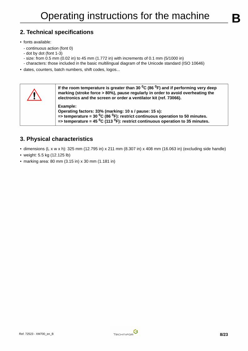
2. Technical specifications• fonts available:
- continuous action (font 0)- dot by dot (font 1-3)- size: from 0.5 mm (0.02 in) to 45 mm (1.772 in) with increments of 0.1 mm (5/1000 in) - characters: those included in the basic multilingual diagram of the Unicode standard (ISO 10646)
• dates, counters, batch numbers, shift codes, logos...
3. Physical characteristics
• dimensions (L x w x h): 325 mm (12.795 in) x 211 mm (8.307 in) x 408 mm (16.063 in) (excluding side handle)
• weight: 5.5 kg (12.125 lb)
• marking area: 80 mm (3.15 in) x 30 mm (1.181 in)
If the room temperature is greater than 30 0C (86 0F) and if performing very deep marking (stroke force > 80%), pause regularly in order to avoid overheating the electronics and the screen or order a ventilator kit (ref. 73066).
Example:Operating factors: 33% (marking: 10 s / pause: 15 s):=> temperature = 30 0C (86 0F): restrict continuous operation to 50 minutes. => temperature = 45 0C (113 0F): restrict continuous operation to 35 minutes.
Ref. 72523 - XM700_en_B 8/23

AOperating instructions for the machine B
4. XM700 dimensional drawingRef. 72523 - XM700_en_B 9/23

AOperating instructions for the machine B
5. List of accessories available upon requestThe accessories mentioned below are available upon request.
M-Travel
Column stand
Battery + charger
Protective screen film
Side handle
Ref. 73289 Wheeled carry case containing protective foam, which protects the machine and its accessories
Ref. 73118 • Marking machine support with height adjustment range of 300 mm (11.811 in).
• The aluminum table with t-slots for mounting standard accessories or specific tooling.
Ref. • Europe: 75887• UK: 75888
• USA: 75889• Switzerland: 75890• China: 75891
• Japan: 75892
Held by a belt, the battery allows the user total autonomy of movement. Battery + belt + cable + charger kit
Ref. 75991 Additional battery alone
Ref. 75352 Protective screen film x1
Ref. 72186 Used to improve handling in particular situations. The handle is screwed onto the right or left hand side of the machine.
Ref. 72523 - XM700_en_B 10/23

AOperating instructions for the machine B
Lifting ringTouch screen pen
Ventilator
Marking area lighting
1 : Ventilator (optional) 2 : Marking area lighting (optional)
Ref. 52307 Additional lifting ring to replace a lost ring
Ref. 64588 Touch screen pen
Ref. 73066 Used to cool the stylus when running at a very high operating factor.
Ref. 74606 This accessory is used to light the marking area using a high power LED mounted under the marking head.
1
2
Ref. 72523 - XM700_en_B 11/23

AOperating instructions for the machine B
Dimensional drawing: Side handleDimensional drawing: Ventilator
Dimensional drawing: Marking area lighting
Ref. 72523 - XM700_en_B 12/23

CCInstallation
1. Coordinate system
The coordinate system used in our machines is shown in the following diagram.
The origin position is defined by the dimensions of 5.5 mm (0.217 in) (dimensions between the point axis and the edge of the window). Tolerance: +/- 1 mm (0.039 in)
Coordinate system
1 : Stylus: origin 2 : X axis - Travel distance 80 mm (3.15 in) 3 : Y axis - Travel distance 30 mm (1.181 in)
The coordinates are given as absolute coordinates in relation to the origin position.
With the marking gun held in front of the operator:
• X axis: horizontal axis going from left to right
• Y axis: descending vertical axis
When a marking cycle is launched, the stylus always begins at the origin point and returns to the origin at the end of the cycle.
When the marking gun is held against the part to be marked, do not apply excessive pressure on the handles. This risks causing flexion and an incorrect distance between the part and the point.
Note: The optimal distance between the point and the part to be marked (adjustment along Z) that allows the use of all marking force percentages is 6 mm (0.236 in). This distance is factory-set when the base is attached. Force percentages between 1 and 10% are reserved for very fine marking.
1
2
3
Ref. 72523 - XM700_en_B 13/23

AInstallation C
To bring the point close to the part, follow the foot adjustment procedure below:Loosen the screws until the foot slides (4 hex spanner).
Position the foot at the desired distance (L).
1 : Screws 2 : Supporting leg
3 : Tooling plate (example: 2 mm (0.079 in) thickness)4 : Non-slip surface 5 : Slide gauge: depth gauge
Ref. 72523 - XM700_en_B 14/23
AInstallation C
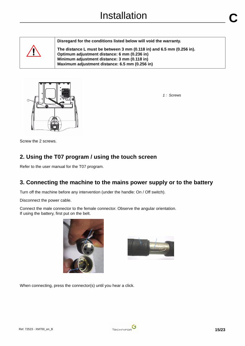
Screw the 2 screws.
2. Using the T07 program / using the touch screen
Refer to the user manual for the T07 program.
3. Connecting the machine to the mains power supply or to the battery
Turn off the machine before any intervention (under the handle: On / Off switch).
Disconnect the power cable.
Connect the male connector to the female connector. Observe the angular orientation. If using the battery, first put on the belt.
When connecting, press the connector(s) until you hear a click.
Disregard for the conditions listed below will void the warranty.
The distance L must be between 3 mm (0.118 in) and 6.5 mm (0.256 in). Optimum adjustment distance: 6 mm (0.236 in)Minimum adjustment distance: 3 mm (0.118 in)Maximum adjustment distance: 6.5 mm (0.256 in)
1 : Screws
Ref. 72523 - XM700_en_B 15/23

AInstallation C
Turn on the machine by flipping the switch to the "ON" position (under the handle).4. Battery - charger
Battery performances
Charging time with the fast charger (supplied with the machine): 2 h
Operating time: 1h30 - 2h30 The operating time depends on the number of characters per minute (marking speed) and the impact force (marking depth).
After this time, the voltage delivered by the battery becomes too low. A warning message appears on the screen. In this case, it is impossible to launch marking. The screen switches off. Put the On/Off switch in the "O" (Off) position (even though the screen is already switched off). Otherwise the battery continues to discharge, thus reducing its service life.
Connect the charger to the battery in place of the machine. Charging time is 3 hours maximum. When the battery is charged, the indicator light on the charger shows green.
Recommendations for extending the service life of the battery
A properly maintained battery lasts for at least 200 charging and discharging cycles. To avoid sudden deterioration in the battery, take the following precautions:
• Charging/discharging temperature: 5 0C (41 0F) - 45 0C (113 0F) (optimal conditions: 10 0C (50 0F) -
30 0C (86 0F))
• Use the fast charger supplied with the machine; this prevents overcharging thanks to its charge status/charge completion detection.
- battery charging: red light - battery charged: green light
Storage
It is best to store the battery semi-charged. It discharges naturally over time, with no impact on its service life. Avoid storing the battery for more than 6 month(s) without putting it through a partial charging cycle (1 h approximately).
The battery should be stored in a cool, dry location (humidity level: 65%).
Storage temperature:
• 1 year: -20 0C (-4 0F) -> 25 0C (77 0F)
• 3 months: -20 0C (-4 0F) -> 45 0C (113 0F)
• 1 month: -20 0C (-4 0F) -> 60 0C (140 0F)
After disconnecting from the power supply using the switch, wait for 5 seconds before resetting to the ON position. Otherwise the machine will not start up (black screen).
Ref. 72523 - XM700_en_B 16/23

AInstallation C
Recommendations• Do not dismantle, open or destroy the battery.
• Keep the battery away from heat sources and fire. Do not store in full sunlight.
• Do not short-circuit the battery.
• Do not remove the battery from its packaging until you are ready to use it.
• Do not subject the battery to mechanical impacts.
• In the event of cell leakage, do not allow the liquid to come into contact with the skin or eyes. In the event of contact, rinse thoroughly with water and consult a doctor.
• Do not use any charger other than that supplied with the machine.
• Do not use any cells or any battery other than those supplied with the machine.
• Keep the battery out of the reach of children.
• Clean the battery and the cable with a dry cloth if necessary.
• The battery should be charged up before use. Consult the charging instructions given in the manual.
• Do not leave the battery on charge for long periods of time when not in use.
• Use the battery only for the intended applications.
• If possible, remove the battery from the machine when not in use.
Ref. 72523 - XM700_en_B 17/23

DDPreventive maintenance The maintenance operations listed here are intended as a guideline, and should be implemented upon reception of the material. In a highly polluted environment, these operations may need to be performed more frequently.
1. Every three months
• Clean the point with a dry cloth. Visually inspect the condition of its end.
• To access the point, remove the stylus using a 10 mm open-ended spanner.
1 : Knurling attachment 2 : 10 mm open-ended spanner
The point must not be nicked. The end radius must be regular. These faults have a direct impact on marking quality.
- If the point is nicked, the point impact diameters are no longer circular. - If the point radius is excessively worn, the point impact diameters will be larger. Consequently the line is wider
and shallower, making small characters difficult to read.
• Check the length of the spring housed behind the point. It should be changed if it measures less than 22 mm (0.866 in). The point could remain embedded in the material to be marked (excessive marking force in a material that is too soft).
Unplug the power supply plug before beginning any cleaning or maintenance operation (power cable or battery cable).
Do not apply oil or grease to any element of the stylus or marking head.
Never remove the stylus when it is hot (risk of burns and deformation of the parts).
Never force the 10 mm spanner.
When refitting, do not use the 10 mm spanner. Hand tighten at the knurling attachment.
2
1
Ref. 72523 - XM700_en_B 18/23

APreventive maintenance D
2. Every yearHave the marking head serviced by Gravotech.
This operation includes:
• complete dismantling of the machine
• cleaning of the mechanical elements
• replacement of the point and its spring
• verification of the condition of the motors and the belt
• reassembly and adjustment of mechanical elements
• debugging of the head in an enclosure
• marking tests
This maintenance list was established based on a marking frequency of:
• 1 cycle(s) every 2 minutes
• 15 characters 3 mm (0.118 in) high per cycle
• 8 hours of operation per day on 50 DaN/mm2 (72518.869 lb/in2) steel
During servicing of the marking head, Gravotech can provide identical rental equipment so that production is not interrupted.
3. General maintenance
Maintenance consists of regular monitoring of marking quality. Intensive use of the equipment can impact the guiding systems of the carriage or the stylus point, and may result in distortion of the characters.
Contact your distributor to schedule an appointment for servicing. This "tune-up" does not take a long time.
When removing/replacing the end of the stylus, check that there are no hard impurities on the male and female threads, to prevent the assembly from seizing up.
Ref. 72523 - XM700_en_B 19/23

EEWearing and spare parts Please give the item codes with your order to speed processing.
1. Wearing parts
Styli:
Points:
Repair kits:
Reference Description
73067 Stylus M2S
Reference Description
73508 Carbide point 60° radius 0.2 mm (0.008 in) for stylus M2S
73533 Carbide point 90° radius 0.2 mm (0.008 in) for stylus M2S
73509 Carbide point 120° radius 0.2 mm (0.008 in) for stylus M2S
Reference Description
73296 M2S stylus repair kit (spring/washer)
Ref. 72523 - XM700_en_B 20/23

FFEmitted vibration level
1. Test code
Measurement method
The measurements were taken according to the regulations of standard ISO 5349-1 (2001).
Measurement equipment used:
• spectrum analyser M+P international Vib Pilot VP8
• accelerometer PCB Piezotronics 356A32
Material used for marking:
• XM700 handheld machine
• power supply or battery (standard)
• magnetic tray to hold the plate
The assembly is placed on a concrete floor.
A new plate is used for each test.
Readings are taken at the 3 handle(s), varying the marking force and speed (handles: main, side, upper).
2. Vibration information
The maximum vibration is generated on the upper handle at maximum marking force and speed.
The maximum vibration to which the hand/arm system is exposed is less than 2.2 m/s².
Ref. 72523 - XM700_en_B 21/23
GGNoise emission of the machine
1. Test code
Measurement method
The measurements were taken according to the regulations of standard ISO 12001: 1996.
Measurement equipment used:
• 01dB - Stell integrated sonometer, SIP 95 S, # 20394
• Cal 01 calibrator, # 40141
Material used for marking:
• type XM700 machine mounted on a column stand
• one electronic command unit
The unit is placed on a wood workbench in a workshop where the background noise level is negligible compared with the noise emitted by the machine. The work station, situated more than 2 m (6.562 ft) from any separator, is designed for a standing operator.
The marking is carried out using a M2S stylus on a steel plate with dimensions of 110 mm (4.331 in) x 100 mm (3.937 in) x 1 mm (0.039 in) clamped to a base support. A new plate is used for each test.
Definition of the microphone position
The microphone is positioned 0.5 m (1.64 ft) in front of the machine and 1.6 m (5.249 ft) from the floor (operator in a standing position, holding the machine).
Test conditions
• marking speed: 100%
• movement speed: 100%
• marking quality: 100%
• stroke force: 50%
• marking of 2 line(s) of 10 character(s) 5 mm (0.197 in) high
• steel plate with dimensions 110 mm (4.331 in) x 100 mm (3.937 in) x 1 mm (0.039 in)
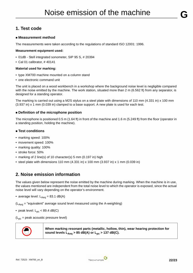
2. Noise emission information
The values given below represent the noise emitted by the machine during marking. When the machine is in use, the values mentioned are independent from the total noise level to which the operator is exposed, since the actual noise level will vary depending on the operator’s environment.
• average level: LAeq = 83.1 dB(A)
(LAeq = "equivalent" average sound level measured using the A-weighting)
• peak level: Lpc < 89.4 dB(C)
(Lpc = peak acoustic pressure level)
When marking resonant parts (metallic, hollow, thin), wear hearing protection for sound levels LAeq > 85 dB(A) or Lpc > 137 dB(C).
Ref. 72523 - XM700_en_B 22/23

HHAppendix To contact the Gravotech Group
www.gravotech.com
FRANCEGravoTech Marking SAS466, rue des Mercières
69140 RILLIEUX-LA-PAPETel.: +33 (0)4 78 55 85 85Fax: +33 (0)4 78 55 22 94
E-mail: [email protected]
U.S.A.GravoTech Inc.
2200 Northmont ParkwayDULUTH, GA 30096Tel.: +1 704 525 5230Fax: +1 704 525 5240
E-mail: [email protected]
CANADATechnifor Canada
27-5250 Satellite DrMISSISAUGA, ONTARIO L4W 5G5
Tel.: +1 905 507 3998Fax: +1 905 507 4223
ENGLANDGravograph UK Ltd
Unit 3 Trojan Business CentreTachbrook Park Estate
LEAMINGTON SPA CV34 6RH WarwickshireTel.: +44 19 26 88 44 22Fax: +44 19 26 88 31 05
E-mail: [email protected]
ITALYGravoTech Italia Srl
Via Rivera, 13810040 ALMESE (TO)
Tel.: +39 011 935 27 14Fax: +39 011 934 59 42E-mail: [email protected]
SWITZERLANDGravograph Switzerland
Champ Olivier 2Ch 3280 MORAT
Tel.: +41 26 678 7200Fax: +41 26 678 7222
E-mail: [email protected]
GERMANYGravoTech GmbHAm Gansacker 3a79224 UMKIRCH
Tel.: +49 7665 5007-0Fax: +49 7665 5007-77
E-mail: [email protected]
BENELUXGravograph Benelux
Molenberglei 162627 SCHELLE
Tel.: +32 3 880 6200Fax: +32 3 888 1997
E-mail: [email protected]
AUSTRIAGravoTech GmbH
Gewerbepark 43202 HOFSTETTEN
Tel.: +43 27 23 78 568Fax: +43 27 23 78 562
E-mail: [email protected]
SWEDENGravoTech AB
Vretenborgsvägen, 28SE-126 30 HÄGERSTEN
Tel.: +46 8 658 15 60Fax: +46 8 658 15 64
E-mail: [email protected]
POLANDGravoTech Sp. z o.o.ul. Kobierzycka 20 BAPL 52-315 WROCŁAWTel.: +48 71 796 04 01Fax: +48 71 796 04 02
E-mail: [email protected]
CZECH REPUBLICTechnifor SroMezirka 775/160200 BRNO
Tel.: +420 725 016 858E-mail: [email protected]
RUSSIAOOO GravoTech Russia
Zolotorozhskii Val 32, 52-315111033 MOSCOW
Tel.: +7 495 781 55 19Fax: +7 495 781 55 19
E-mail: [email protected]
TURKEYGravoTech STI Turkey
Atiye Hanım Sokak No. 234752 İÇERENKÖY / İSTANBUL
Tel.: +90 216 577 64 54Fax: +90 216 574 56 02
E-mail: [email protected]
UNITED ARAB EMIRATESGravotech JLT
PO Box 487940Office 610, Tiffany Tower
Jumeirah Lakes Towers - DUBAITel.: +971 (0)4 456 5729Fax: +971 (0)4 456 5538
E-mail: [email protected]
JAPANGravoTech KK
1-25 Takahata-ChoNISHINOMIYA-SHIHYOGO 663-8202
Tel.: +81 798 63 7325Fax: +81 798 63 6280
E-mail: [email protected]
CHINAGravoTech Engraving Equipment Co. Ltd
Building F, No. 1835, DuHui RoadSHANGHAI 201108
Tel.: +86 21 / 24 08 68 88Fax: +86 21 / 24 08 68 00
E-mail: [email protected]
SOUTH KOREAGravoTech Ltd
#1307 Digital Empire685 Gasan-dong, Geumcheon-gu
153-716 SEOULTel.: +82 2 6365 3791Fax: +82 2 6365 3793
E-mail: [email protected]
SINGAPOREGravograph Singapore Pte Ltd
18 Boon Lay Way#07-128 Tradehub 21609966 SINGAPORETel.: +65 6795 2763Fax: +65 6795 7913
E-mail: [email protected]
MALAYSIAGravoTech Sdn Bhd
No. 29, Jalan Puteri 5/10Bandar Puteri
47100 PUCHONG, SELANGORTel.: +60 3 80 685512 & 80 683512
Fax: +60 3 80 612513E-mail: [email protected]
INDIAGravoTech Engineering PVT Ltd
Gat No 2323/1, "Reality Warehousing"Nagar Road
PUNE WAGHOLI 412 207Tel.: +91 20 / 41030000Fax: +91 20 / 41030010
E-mail: [email protected]
SOUTH AFRICAGravoTech (Pty) Ltd
Unit 8 Rutland Mews - 30 Main StreetEastleigh, 1609 EDENVALE
PO Box 734 - Strubens Valley 1735Cell.: +27 (0)71 872 07 17
E-mail: [email protected]
BRAZILTechnifor Pictor Ltda
Av. Dr. Luis Arrobas Martins, 9804781-000 - SAO PAULO SP
Tel.: +55 11 5524 8707Fax: +55 11 5524 8707
E-mail: [email protected]
MEXICOGravoTech S. DE R.L DE C.V
Lago Erne, 246 - Colonia PensilCP 11430 - MEXICO DF
Tel.: +52 55 2978 0177/81/82Fax: +52 55 5357 2765
E-mail: [email protected]
AUSTRALIAGravograph Australia
Unit 3, 9-11 South StreetRYDALMERE N.S.W. 2116
Tel.: +61 29 684 2400Fax: +61 29 684 2500
E-mail: [email protected]
Ref. 72523 - XM700_en_B 23/23