Embed Size (px)
Citation preview

XAPP1095 (v1.0) January 31, 2014 www.xilinx.com 1
© Copyright 2014 Xilinx, Inc. Xilinx, the Xilinx logo, Artix, ISE, Kintex, Spartan, Virtex, Vivado, Zynq, and other designated brands included herein are trademarks of Xilinx in the United States and other countries. AMBA, AMBA Designer, ARM, ARM1176JZ-S are trademarks of ARM in the EU and other countries. HDMI, HDMI logo, and High-Definition Multimedia Interface are trademarks of HDMI Licensing LLC. All other trademarks are the property of their respective owners.
Summary This application note leverages the latest Zynq®-7000 All Programmable SoC (AP SoC) architecture to provide a truly scalable video processor reference design to serve multi-stream/multi-pipeline video processing needs. It also provides user end graphics rendering capability to allow differentiated content creation. It is targeted for applications like multi-viewer displays, video switches, and multichannel video routers, as well as multi-stream up-down converters.
Introduction In the broadcast video landscape, video content flows in various formats across acquisition, contribution, distribution, and consumption sectors. To properly archive, distribute, and display the content, the video signal often needs to be properly processed with an appropriate format conversion process. For example, to correctly display NTSC/PAL signals on a full HD (1080p60) LCD screen, a series of deinterlacing, scaling, chroma upsampling, color correction operations (as well as alpha blending) must be performed. In addition, mixture of user end rendering capability is highly desired to allow differentiated content creation.
The objective of this reference design is to provide a highly demonstrable, broadcast-quality video processing reference design targeted to a wide range of video applications. The Real Time Video Engine Reference Design version 2.1 (RTVE 2.1) provides a user end graphics rendering platform using APIs under Linux v3.3 with a Qt graphics environment, and performs scalable video processing features as those defined in its predecessor (RTVE 2.0 from XAPP1091 [Ref 1]).
The goal is to leverage the latest Zynq-7000 AP SoC architecture and provide the broadcast video industry with a truly scalable video processor reference design to serve multi-stream/pipeline video processing needs in conjunction with user end rendering features. It is targeted for applications like multi-viewer displays, video switches, multichannel video routers, and multi-stream up-down converters. The design includes the following features:
• Programmable video input and output formats
• On-the-fly switchable video sources: HDMI and SD/HD/3G-SDI
• Support for either progressive or interlaced format video
• Multiple video output ports: HD/3G-SDI and HDMI
• Scalable design optimized for different Zynq-7000 AP SoCs
• 2-pipeline: XC7Z030 logic density
• 4-pipeline: XC7Z030 logic density
• Up to 6-pipeline: XC7Z045 logic density
• Completely based on Xilinx AXI infrastructure
• AXI-Lite CPU control interface
• AXI-Memory Map for external memory access
• AXI-Streaming for video streaming among video processing blocks
Application Note: Zynq-7000 AP SoC
XAPP1095 (v1.0) January 31, 2014
Real Time Video Engine 2.1 Implementation in Xilinx Zynq-7000 All Programmable SoCsAuthor: Bob Feng

RTVE 2.1 SoC Design
XAPP1095 (v1.0) January 31, 2014 www.xilinx.com 2
• Full featured video processing on every pipeline
• Motion adaptive and/or edge-adaptive deinterlacer
• Polyphase scaler with on-the-fly customizable coefficient table
• 10-bit 4:4:4 processing engine
• Frame buffer read back
• Composite onto video output with graphic overlay
• Live video picture-in-picture
• Professional fade-in/fade-out effect
• Contrast enhancement through color correction matrix
• Complete Linux 3.3 with Qt framework
• Complete video IO device drivers
• Complete video processing APIs
• User end rendering example
• User software design examples
• Qt web client
• Qt drawing demonstration
RTVE 2.1 SoC Design
The RTVE 2.1 provides a unique dual output-stream video system consisting of two independent subsystem designs:
• Programmable Logic (PL) Subsystem: Responsible for real time video processing using OmniTek Scalable Video Processor (OSVP) [2]
• Processor Subsystem (PS): Responsible for Linux system and user software execution
The dual video outputs can be routed to either the SDI or HDMI output video connectors. Though two video streams are present in the RTVE 2.1, the pixels data/imagery presented on one output cannot be moved to the other output, and thus each output is a unique stream (regardless of which connector to which the streams are routed).

RTVE 2.1 SoC Design
XAPP1095 (v1.0) January 31, 2014 www.xilinx.com 3
RTVE 2.1 comes as 3 variants; these are 2, 4, or 6 video input channels. All other functionality is common. The conceptual video outputs from the RTVE framework are shown in Figure 1.
OSVP Overlay Rendering (Primary Output)
Up to eight OSVP video streams can be combined with a dedicated programmable logic (PL) frame-buffer to provide the primary RTVE output stream. The use of alpha-blending techniques and layer prioritizing will be demonstrated using the Xilinx video combiner. More detailed description of OSVP and its RTVE FPGA implementation can be found in the OSVP user's guide [Ref 2] and XAPP1091 [Ref 1], respectively.
X-Ref Target - Figure 1
Figure 1: RTVE 2.1 Outputs

RTVE 2.1 SoC Design
XAPP1095 (v1.0) January 31, 2014 www.xilinx.com 4
The Linux RTVE application draws dedicated graphics onto this stream to demonstrate the overlaying of end-product information with live video streams, as shown in Figure 2.
The user can freely move or resize any image on this output using the provided RTVE web client application software.
Linux Frame Buffer Rendering (Secondary Output)
The secondary output video stream provides the user with an interactive but statically positioned display showing the following:
• Linux web-client of the RTVE application
• Qt demonstration image
This video output displays the RTVE application's web page and provide the user with a local interactive system. The user cannot move or resize any image on this output.
The Linux rendering frame buffer is physically located in the Processor Subsystem (PS) dedicated DDR memory space.
X-Ref Target - Figure 2
Figure 2: OSVP Overlay Output

RTVE 2.1 SoC Design
XAPP1095 (v1.0) January 31, 2014 www.xilinx.com 5
SoC System Design Block Diagram
The RTVE 2.1 design comprises a super-set of its predecessor RTVE 2.0 design [Ref 1]. The key extra features are:
• Addition of a second video stream output
• Addition of Zynq-7000 AP SoC support
• Linux is the underlying software framework as opposed to XilKernel on the MicroBlaze™ processor
• All software runs on the ARM CPU instead of on a MicroBlaze processor
• Addition of output video crosspoint
X-Ref Target - Figure 3
Figure 3: Linux Frame Buffer Output

RTVE 2.1 SoC Design
XAPP1095 (v1.0) January 31, 2014 www.xilinx.com 6
The majority of these extra features are based on software running from the Processor Subsystem (PS) on the Zynq-7000 AP SoC. Figure 4 shows the conceptual data-flow through the Zynq-7000 AP SoC system showing the PS and PL allocations and responsibilities.
X-Ref Target - Figure 4
Figure 4: RTVE 2.1 System Block Diagram
RTVE 2.1 SoC Design
XAPP1095 (v1.0) January 31, 2014 www.xilinx.com 7
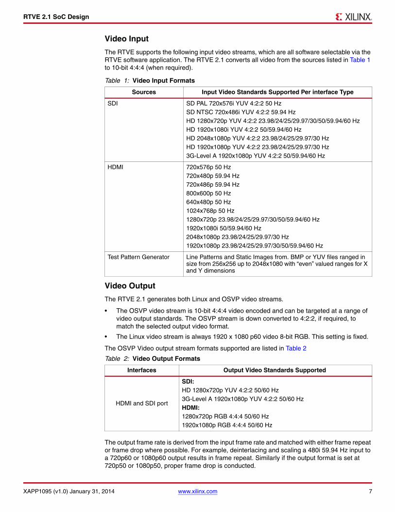
Video Input
The RTVE supports the following input video streams, which are all software selectable via the RTVE software application. The RTVE 2.1 converts all video from the sources listed in Table 1 to 10-bit 4:4:4 (when required).
Video Output
The RTVE 2.1 generates both Linux and OSVP video streams.
• The OSVP video stream is 10-bit 4:4:4 video encoded and can be targeted at a range of video output standards. The OSVP stream is down converted to 4:2:2, if required, to match the selected output video format.
• The Linux video stream is always 1920 x 1080 p60 video 8-bit RGB. This setting is fixed.
The OSVP Video output stream formats supported are listed in Table 2
The output frame rate is derived from the input frame rate and matched with either frame repeat or frame drop where possible. For example, deinterlacing and scaling a 480i 59.94 Hz input to a 720p60 or 1080p60 output results in frame repeat. Similarly if the output format is set at 720p50 or 1080p50, proper frame drop is conducted.
Table 1: Video Input Formats
Sources Input Video Standards Supported Per interface Type
SDI SD PAL 720x576i YUV 4:2:2 50 HzSD NTSC 720x486i YUV 4:2:2 59.94 HzHD 1280x720p YUV 4:2:2 23.98/24/25/29.97/30/50/59.94/60 HzHD 1920x1080i YUV 4:2:2 50/59.94/60 HzHD 2048x1080p YUV 4:2:2 23.98/24/25/29.97/30 HzHD 1920x1080p YUV 4:2:2 23.98/24/25/29.97/30 Hz3G-Level A 1920x1080p YUV 4:2:2 50/59.94/60 Hz
HDMI 720x576p 50 Hz720x480p 59.94 Hz720x486p 59.94 Hz800x600p 50 Hz640x480p 50 Hz1024x768p 50 Hz1280x720p 23.98/24/25/29.97/30/50/59.94/60 Hz1920x1080i 50/59.94/60 Hz2048x1080p 23.98/24/25/29.97/30 Hz1920x1080p 23.98/24/25/29.97/30/50/59.94/60 Hz
Test Pattern Generator Line Patterns and Static Images from. BMP or YUV files ranged in size from 256x256 up to 2048x1080 with “even” valued ranges for X and Y dimensions
Table 2: Video Output Formats
Interfaces Output Video Standards Supported
HDMI and SDI port
SDI:HD 1280x720p YUV 4:2:2 50/60 Hz3G-Level A 1920x1080p YUV 4:2:2 50/60 HzHDMI:1280x720p RGB 4:4:4 50/60 Hz1920x1080p RGB 4:4:4 50/60 Hz

RTVE 2.1 SoC Design
XAPP1095 (v1.0) January 31, 2014 www.xilinx.com 8
Hardware Platform
The RTVE 2.1 uses an OmniTek OZ745 Development Kit [Ref 3].
Programmable Logic Subsystem FPGA Hardware Design
The RTVE 2.1 FPGA hardware design is very similar to its predecessor version 2.0 as described in XAPP1091 [Ref 1]. The real time video processing part using the OSVP [Ref 2] scalable processor remains identical.
However, by leveraging a high performance AXI interconnect port [Ref 4] between the PS and PL subsystems, the on-screen display (OSD) combiner [Ref 1] in the PL also accepts the graphics rendering content residing in the Linux frame buffer as one of its input streams.
In addition, a new 2x2 video output crosspoint switch is used to allow dynamic switching between the OSVP overlay frame buffer and the Linux frame buffer on either HDMI or SDI outputs.
Processor Subsystem Software Design
The architecture of the software environment used on OmniTek's OZ745 video development board is illustrated in Figure 5.
X-Ref Target - Figure 5
Figure 5: RTVE 2.1 Software Architecture

RTVE 2.1 SoC Design
XAPP1095 (v1.0) January 31, 2014 www.xilinx.com 9
OmniTek API
The key feature of this architecture is the OmniTek API which, together with the associated OmniTek API Shim, ensures that the interface presented to any application that runs on the OmniTek OZ745 video development board stays the same, regardless of any changes in the facilities offered on the OZ745 board. This means that the same source code can be used for any application running on the board, even when the underlying firmware has changed. It continues to be usable even if the interface to the OZ745 board changes to a PCIe bus or the operating system changes from Linux to Windows. The OmniTek API and the associated Shim provide the application with a cross-platform environment in which to work.
This works through the establishment of a consistent structure and nomenclature for the capabilities offered by the OmniTek IP blocks implemented in the Zynq-7000 AP SoC PL. The consistent structure, etc., allows the OmniTek API at boot time to 'discover' the operating system, the host interface, and the capabilities offered by the board firmware, and create appropriate kernel mode drivers for these items. There is no need for the user to write any kernel mode code.
These drivers automatically give the application a consistent interface to these components.
For non-OmniTek components of the hardware and firmware, the API sets up a wrapper known as the API Shim around their 'barebones' drivers (penetrated only by the OSVP block's own API) which effectively extends the same consistent interface to those components as well. The OSVP block's own barebones driver (omni_vp) is also placed alongside the other barebones drivers within the API Shim.
Note: The main module at the top of the structure is key to the operation of the OmniTek API. If this block is not able to identify the OSVP block within the firmware on the board, the assumption is made that the OmniTek firmware is not implemented on the board and the set-up process conducted by the OmniTek API is not run.

RTVE 2.1 SoC Design
XAPP1095 (v1.0) January 31, 2014 www.xilinx.com 10
The RTVE Application
The architecture of the RTVE Application is shown in Figure 6:
The operation of the application is run by the main loop.
The user gives their commands either by making selections in the provided web-based GUI, or by issuing commands either at a console or via Telnet. The commands issued via Telnet take exactly the same form as those issued at a console and details can be obtained using either method by giving the command h (for Help).
X-Ref Target - Figure 6
Figure 6: RTVE Application

RTVE 2.1 SoC Design
XAPP1095 (v1.0) January 31, 2014 www.xilinx.com 11
These commands are directed from the user interface to the command processing module which sorts the commands into ones that can be carried out directly (typically requests for status information) and ones specifying a change in setup. When a change in setup is requested, the command processing module advises the main loop that a user command has been issued and stacks the command in a buffer. In order to ensure that all operations are carried out correctly, the main loop only executes setup changes between frames so the details of the command are retained in the buffer until that time, along with the details of any subsequent commands that are issued before the end of frame. Then at the end of frame, the main loop processes all the setup change commands that have been issued and clears the buffer ready for the next set of setup change commands to be issued.
The way the main loop executes the commands is by issuing commands to the OSVP API which interprets these in terms of instructions to the OmniTek API and/or instructions to the drivers in the API Shim.
SD Card Image
A SD card image is delivered as a part of the OZ745 package. (Its updated version is available to registered OZ745 board users from the OmniTek website.)
The items in Figure 7 shown in dark grey are referred to as the 'base' components of the image and are associated with booting the hardware and setting up the operating system. The other items relate to the two reference designs supplied for the OZ745 - the RTVE 2.1 design described in this document and an evaluation reference design which demonstrates, among other things, how to use the Qt graphics software that is delivered as part of the board support
X-Ref Target - Figure 7
Figure 7: OZ745 SD Card Image

RTVE 2.1 SoC Design
XAPP1095 (v1.0) January 31, 2014 www.xilinx.com 12
package for the OZ745. (For further information about the evaluation reference design, refer to the OZ745 Evaluation Reference Design (ERD) Guide [Ref 3], provided for the OZ745 board.)
Depending on the version of the OmniTek OSVP IP Core purchased (evaluation, standard, or full), the various components on the SD image can be supplied as either encrypted netlists, encrypted source code, or full source code. Various build scripts, Vivado® Design Suite project files, and software project files might also be provided. This, too, depends on the version of the OSVP purchased.
Modifying the Supplied Software
The degree to which the supplied code can be modified is also dependent on the version of the OSVP purchased.
For the free evaluation package, a user can:
• Build and modify RTVE firmware
• Build and modify RTVE application
• Build and modify Qt and demo applications
But the user cannot:
• Rebuild SD image
• Rebuild Linux kernel and then run RTVE application
With a full version, however, the user gets full access to OmniTek's source code. However, it is strongly advised to consult OmniTek before converting any systems built using this code into a commercial product to:
• Ensure continuing compatibility with future releases of the OZ745 board firmware and software; and
• Avoid compatibility issues with related products that also take advantage of OmniTek's API technology.

Build the RTVE 2.1 Project
XAPP1095 (v1.0) January 31, 2014 www.xilinx.com 13
Build the RTVE 2.1 Project
The RTVE 2.1 project files come with both hardware and software sets. Figure 8 shows the project file structure:
The project is implemented based upon the latest Xilinx Vivado design flow. Vivado design suite v2013.3 is used. The hardware and software pieces are separately built using Vivado and XSDK tool sets.
Hardware Build Flow1. Open a command window under Windows or a C or Bash shell under Linux
2. Move to directory release/hw/rtve_2_1a_oz745_6x/
3. Execute create_project.bat under Windows or create_project.csh under Linux. Or directly run Vivado in command mode:
vivado -mode batch -source create_project.tcl
4. Execute generate_bitstream.bat under Windows or generate_bitstream.csh under Linux. Or directly run Vivado in command mode:
vivado -mode batch -source generate_bitstream.tcl
The above commands automatically create a series of RTVE project files and subdirectories where Vivado tools pass through necessary synthesis, map, placement and route processes and generate the final Zynq programmable logic bitstream rtve_2_1a_oz745_6x.bit.
X-Ref Target - Figure 8
Figure 8: RTVE 2.1 Project File Structure

Build the RTVE 2.1 Project
XAPP1095 (v1.0) January 31, 2014 www.xilinx.com 14
Software Build Flow
On the software portion, since most of system libraries and OmnitekAPI are provided as prebuilt binary images, this application note only focus on the RTVE application software build process:
1. Create a new subdirectory rtve_workspace under the release/eval/sw directory.
2. Launch XSDK pointing to the newly created rtve_workspace.
3. Import the rtve software project by selecting File → Import.
4. In the Import dialog box, select General → Existing Projects into Workspace as shown in Figure 9 and click Next.
5. Under Import Projects, select the Select root directory radio button, and use the Browse button to locate the release/sw/eval/sw/rtve directory.
X-Ref Target - Figure 9
Figure 9: Populate the RTVE SDK Workspace

Build the RTVE 2.1 Project
XAPP1095 (v1.0) January 31, 2014 www.xilinx.com 15
6. The XSDK identifies the project and automatically selects it for importing as shown in Figure 10. Click Finish to import.
7. Click OK and then select Project → Clean → OK to clean the project and click Project → Build All to rebuild the RTVE software.
8. A Zynq SoC executable "RTVE" binary is generated under the release/sw/eval/sw/rtve/rtve_2_1 directory.
X-Ref Target - Figure 10
Figure 10: Import RTVE Application Software Project

Reference Design Checklist
XAPP1095 (v1.0) January 31, 2014 www.xilinx.com 16
Reference Design Checklist
The reference design checklist is shown in Table 3.
Resource Utilization
The resource utilization breakdown is shown in Table 4.
Table 3: Reference Design Checklist
Simulation
Functional simulation performed Y
Timing simulation performed N
Testbench used for functional and timing simulations Functional Only
Testbench format VHDL
Simulator software and version used ModelSim 6.6d
SPICE/IBIS simulations N/A
Implementation
Synthesis software tools and version used Vivado Design Suite 2013.3
Implementation software tools and version used Vivado Design Suite 2013.3
Static timing analysis performed Y
Hardware Verification
Hardware verified Y
Hardware platform used for verification OmniTek OZ745 Board
Table 4: RTVE 2.1 Resource Breakdown
BRAM/FIFO 36 bit FF LUT DSP
OSVP Core
OSVP2 (2 input channels) 108 22,240 18,412 102
OSVP4 (4 input channels) 192 41,398 34,623 204
OSVP8 (8 input channels) 379 80,500 69,406 408
Supporting IP
SDI Input (per input channel) 0 1,808 1,849 0
SDI Output 0 414 543 0
HDMI Input 0 444 297 0
HDMI Output 0 113 61 0
AXI Interconnect: CPU peripherals 8,692 5,928
AXI Interconnect: High Bandwidth 9 21,457 15,546
Onscreen Display (4 channels) 7,554 4,958
DDR3 MIG (supporting 4 - 8 channels) 19,305 17,500
Video Timing Controller 737 768

Demonstration Setup
XAPP1095 (v1.0) January 31, 2014 www.xilinx.com 17
Demonstration Setup
By default RTVE 2.1 provides a demo with 6-pipeline OSVP configuration. A prebuilt OZ745 board support package can be loaded to serve a quick evaluation purpose. The board support package is located in the sd_image/ subdirectory of the evaluation project file set. Simply copy everything from the directory to an empty and pre-formatted secure digital (SD) card.
Hardware Inventory• One OmniTek OZ745 Zynq-7000 AP SoC Video Development Kit [Ref 3]
• One HDMI monitor supporting at least 720p@60 Hz(1280x720p@60 Hz)
• Four SDI video sources
• One SDI monitor or analyzer (optional)
• One HDMI video source (optional)
• One HDMI cable
• Five SDI cables
• One WiFi Ethernet router (providing DHCP server)
• One Ethernet cable
• One mini USB cable (for UART console)
• One PC with at least one free USB port
• One set of USB keyboard and mouse
• One SD card loaded with the OZ745 board support package
Hardware Setup
The hardware setup with all necessary wire connection is shown in Figure 11. The design uses five SDI ports with four inputs and one output respectively. The HDMI input and output ports are bounded together on J113, on which the output connector is on the top and the input connector is on the bottom.
The Ethernet port of OZ745 is recommended to be connected to the DHCP capable WiFi router’s LAN port so that an IP address can be assigned.
The SD card with the board support package is to be plugged into the OZ745 SD card slot.
The keyboard and mouse are connected to the on board USB ports.

Demonstration Setup
XAPP1095 (v1.0) January 31, 2014 www.xilinx.com 18
Software Inventory• Microsoft Windows 7/XP/Vista
• Silicon Labs CP210x USB to UART Bridge Device Driver [Ref 5]
• PuTTY [Ref 6] or any other UART console
Boot and Launch the Demo Design
Prior to launching the demo, all hardware and software inventory items must be prepared, connected, and installed. In the UART console, the designated COM port needs to be specified to match what Windows has assigned to the Silicon Labs USB-to-UART Bridge [Ref 5]. The baud rate is set to 115200. The Data bits is 8 and Stop bits is 1. The Parity and Flow Control are both set to None.
To boot the design, plug the SD card into the OZ745 SD card slot and power on the board. Boot messages are displayed on the UART console if it is opened early enough. After the boot, the on board Zynq-7000 AP SoC is ready for the Linux system operation and user program execution. An OZ745> prompt is given as shown in Figure 12.
X-Ref Target - Figure 11
Figure 11: OZ745 RTVE 2.1 Demo Setup
X-Ref Target - Figure 12
Figure 12: OZ745 UART Console

Demonstration Setup
XAPP1095 (v1.0) January 31, 2014 www.xilinx.com 19
Perform the following steps to launch the demo:
• Type /mnt/scripts/rtve.sh start to start the RTVE application. This must be done first before any other steps.
• Type /mnt/scripts/qt_demos.sh web to start the Qt web client which can be operated through the USB keyboard and mouse.
• Type /mnt/scripts/qt_demos.sh example to start the Qt drawing example.
• Type /mnt/scripts/qt_demos.sh sidebyside to start both the web client and the Qt example side-by-side.
• Type /mnt/rtve/scripts/switch_sources.sh [sdi|hdmi] [rtve|fb] to switch the RTVE or Linux frame buffers to either of SDI and HDMI outputs.
• Type top Linux command to check the ARM CPU load.
RTVE 2.1 Control GUI
The RTVE 2.1 control GUI is accessible through either a remote web browser over the same IP subnet or the local web browser client running on the Linux Qt environment. The GUI layout for any browser is identical and serves the exact same purpose (shown in Figure 13).
The input video source options are listed on top-left of the GUI. The options are: any of the four SDI inputs corresponding to SDI2, SDI3, SDI4 and “Eye”, the HDMI input, the internal Linux frame buffer, and the built-in test pattern generator. All SDI and HDMI input formats are automatically detected. The Linux frame buffer is fixed at 1080p 60 Hz. The prebuilt test patterns are selectable from the top-right pull-down menu.
The left side of the control GUI also gives possible settings for each video processing pipeline including the selection of a video source, deinterlacer modes, scaler geometry, and OSD alpha percentage value. The GUI right side allows controls to the video output screens. The output formats can be changed by clicking the desired radio button.
A quadratic layout diagram is shown on the bottom right side. By clicking the Next Layout button, the user is allowed to rotate between various preset layouts. It is also possible to scale up and down any of the four video windows by clicking and dragging the border or corner of each window.
By clicking and holding in the middle of each window, the user can move it around anywhere within the output screen. Windows are allowed to overlap each other. By changing the alpha blending percentage value for each window, the user can easily obtain the picture-in-picture feature. RTVE 2.1 allows a maximum of 8 windows to overlap to each other with individually controllable transparency or fade-in/fade-out effects.
In addition, the GUI software allows the scaler output of each processed video pipeline to be captured by clicking the Snapshot Scaler button on the top right side.

Reference Design
XAPP1095 (v1.0) January 31, 2014 www.xilinx.com 20
Reference Design
The reference design is available at: www.xilinx.com/member/brtve. Table 5 shows the Reference Design checklist.
X-Ref Target - Figure 13
Figure 13: RTVE 2.1 Control GUI
Table 5: Reference Design Checklist
Parameter Description
General
Developer name Omnitek
Target devices Zynq-7000 All Programmable SoC
Source code provided Yes
Source code format VHDL and C
Design uses code or IP from existing Xilinx application note reference designs, CORE Generator™ tool, or third party reference designs provided for EDK and video cores generated from the CORE Generator tool?
Yes
Simulation
Functional simulation performed? Yes

References
XAPP1095 (v1.0) January 31, 2014 www.xilinx.com 21
References This document uses the following references:
1. Real Time Video Engine 2.0 Implementation in Kintex-7 FPGAs (XAPP1091)
2. OSVP Scalable Video Processing Suite for Xilinx FPGAs
3. OZ745 Zynq-7000 AP SoC Video Development Kit
4. Zynq-7000 All Programmable SoC Technical Reference Manual (UG585)
5. Silicon Lab CP210X to UART Bridge Drivers
6. PuTTY (www.putty.org)
Revision History
The following table shows the revision history for this document.
Notice of Disclaimer
The information disclosed to you hereunder (the “Materials”) is provided solely for the selection and use of Xilinx products. To the maximum extent permitted by applicable law: (1) Materials are made available "AS IS" and with all faults, Xilinx hereby DISCLAIMS ALL WARRANTIES AND CONDITIONS, EXPRESS, IMPLIED, OR STATUTORY, INCLUDING BUT NOT LIMITED TO WARRANTIES OF MERCHANTABILITY, NON-INFRINGEMENT, OR FITNESS FOR ANY PARTICULAR PURPOSE; and (2) Xilinx shall not be liable (whether in contract or tort, including negligence, or under any other theory of liability) for any loss or damage of any kind or nature related to, arising under, or in connection with, the Materials (including your use of the Materials), including for any direct, indirect, special, incidental, or consequential loss or damage (including loss of data, profits, goodwill, or any type of loss or damage suffered as a result of any action brought by a third party) even if such damage or loss was reasonably foreseeable or Xilinx had been advised of the possibility of the same. Xilinx assumes no obligation to correct any errors contained in the Materials or to notify you of updates to the
Timing simulation performed? No
Test bench used for functional and timing simulations?
Functional Only
Test bench format VHDL
Simulator software and version used ModelSim 6.6d
SPICE/IBIS simulations N/A
Implementation
Synthesis software tools/version used Vivado Design Suite 2013.3
Implementation software tools/versions used Vivado Design Suite 2013.3
Static timing analysis performed? No
Hardware Verification
Hardware verified Yes
Hardware platform used for verification Omnitek OZ745 Board
Table 5: Reference Design Checklist (Cont’d)
Parameter Description
Date Version Description of Revisions
01/31/2014 1.0 Initial Xilinx release.

Notice of Disclaimer
XAPP1095 (v1.0) January 31, 2014 www.xilinx.com 22
Materials or to product specifications. You may not reproduce, modify, distribute, or publicly display the Materials without prior written consent. Certain products are subject to the terms and conditions of the Limited Warranties which can be viewed at http://www.xilinx.com/warranty.htm; IP cores may be subject to warranty and support terms contained in a license issued to you by Xilinx. Xilinx products are not designed or intended to be fail-safe or for use in any application requiring fail-safe performance; you assume sole risk and liability for use of Xilinx products in Critical Applications: http://www.xilinx.com/warranty.htm#critapps.


![Xilinx XAPP11095 Real Time Video Engine 2,1 …The RTVE 2.1 design comprises a super-set of its predecessor RTVE 2.0 design [Ref 1]. The key extra features are: † Addition of a second](https://img.dokumen.tips/doc/110x75/610343b6b1939c364104fe3d/xilinx-xapp11095-real-time-video-engine-21-the-rtve-21-design-comprises-a-super-set.jpg)


![Modul 2,1 [Kompatibilitetstilstand]](https://img.dokumen.tips/doc/110x75/616a46b611a7b741a350bd20/modul-21-kompatibilitetstilstand.jpg)


