Embed Size (px)
Citation preview

X9 Model 1901T Repair Manual 1 Revision 0
90-10766 10/26/12
SUPERWINCH X9 MODEL 1901T / 1901TA
PZQ9300010 ,PZQ9300020 , PZQ9300030 ,
PZQ93 00040 & PZQ9300041
REPAIR MANUAL
Superwinch, Inc.
Winch Drive
Putnam, CT 06260
USA
www.superwinch.com

X9 Model 1901T Repair Manual 2 Revision 0
90-10766 10/26/12
Introduction:
The Superwinch X9 is a precision engineered and assembled product designed to
provide you with years of dependable service. This manual is intended to be a guide to
the repair and maintenance of your winch. This manual should always be used to
troubleshoot and repair your winch. Be sure to follow the guidelines below at all times to
assure safety and quality performance from the winch.
CAUTION! The X9 is a 9000 lb. winch. Any winch, wire rope, hook, component or
accessory that is in a damaged condition can result in serious personal injury or
death if used. Improper use of this product can also lead to serious personal injury
or death. Read the owner’s manual for the winch thoroughly before operating.
Always use this manual to troubleshoot and repair the winch.
Always be certain to follow all cautions and warnings listed. Serious personal
injury or death can result from poor winching practice, and / or not following
the guidelines and warnings listed.
Always read each step through completely before performing the step to be
sure all instructions and precautions are understood.
Always use genuine Superwinch replacement parts for maintenance and repair
to maintain the warranty on the product. The use of anything other than
genuine Superwinch replacement parts will void the warranty.
Always replace broken or damaged parts before operating the winch. Never
operate a winch with known broken or damaged parts.
Always use quality tools and test equipment when working on the winch.
Personal injury, damage to the winch, and / or faulty diagnosis can result from
using low-quality or damaged tools or test equipment.
Always use caution in troubleshooting the power source for the winch. Refer
to the manufacturer or supplier of your power source for troubleshooting
guidelines.
X9 Model 1901T Repair Manual 3 Revision 0
90-10766 10/26/12
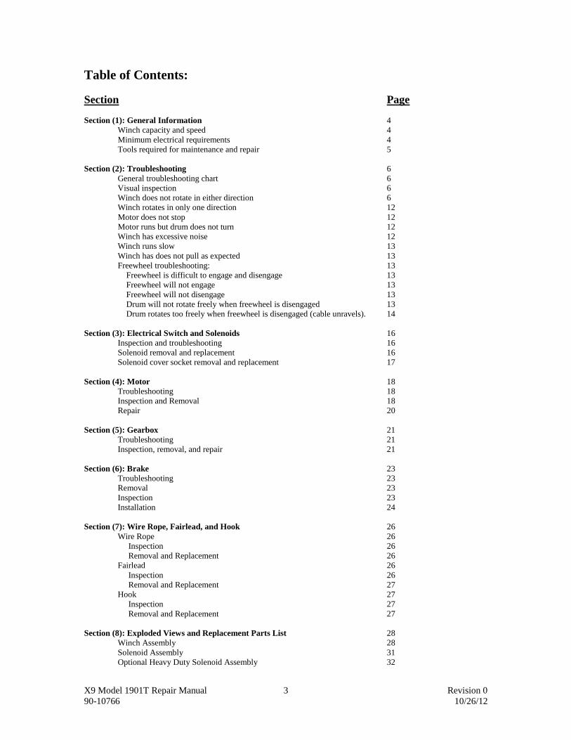
Table of Contents:
Section Page
Section (1): General Information 4
Winch capacity and speed 4
Minimum electrical requirements 4
Tools required for maintenance and repair 5
Section (2): Troubleshooting 6
General troubleshooting chart 6
Visual inspection 6
Winch does not rotate in either direction 6
Winch rotates in only one direction 12
Motor does not stop 12
Motor runs but drum does not turn 12
Winch has excessive noise 12
Winch runs slow 13
Winch has does not pull as expected 13
Freewheel troubleshooting: 13
Freewheel is difficult to engage and disengage 13
Freewheel will not engage 13
Freewheel will not disengage 13
Drum will not rotate freely when freewheel is disengaged 13
Drum rotates too freely when freewheel is disengaged (cable unravels). 14
Section (3): Electrical Switch and Solenoids 16
Inspection and troubleshooting 16
Solenoid removal and replacement 16
Solenoid cover socket removal and replacement 17
Section (4): Motor 18
Troubleshooting 18
Inspection and Removal 18
Repair 20
Section (5): Gearbox 21
Troubleshooting 21
Inspection, removal, and repair 21
Section (6): Brake 23
Troubleshooting 23
Removal 23
Inspection 23
Installation 24
Section (7): Wire Rope, Fairlead, and Hook 26
Wire Rope 26
Inspection 26
Removal and Replacement 26
Fairlead 26
Inspection 26
Removal and Replacement 27
Hook 27
Inspection 27
Removal and Replacement 27
Section (8): Exploded Views and Replacement Parts List 28
Winch Assembly 28
Solenoid Assembly 31
Optional Heavy Duty Solenoid Assembly 32

X9 Model 1901T Repair Manual 4 Revision 0
90-10766 10/26/12
Section (1) - General Information
Performance:
Wire Rope Max. Pulling Capacity
Layer lbs kg
1 9000 4082
2 7365 3340
3 6230 2825
4 5400 2450
5 4765 2161
Load Speed* Motor current*
lbs kg ft/min m/min amps
0 0 32 9.8 73
1000 454 18 5.5 130
2000 907 13.8 4.2 165
4000 1814 9 2.7 240
6000 2722 6 1.8 316
9000 4082 2.5 0.8 420
* Based on first layer performance
Rolling Load Capacity:
Slope* 10% (6) 20% (11) 30% (17) 100% (45)
Lbs** 45,225 30,600 23,500 11,573
Kg** 20,514 13,880 10,659 5,250
* A 10% slope is a rise of one foot in ten feet. Slope in approximate degrees is also shown above. ** All loads shown are for single-line operation. Double line operation with optional pulley block (P/N 7750A) approximately
doubles capacity of winch.
Specifications:
Working load* 9,000 lbs (4082 kg)
Stall Load* 12,7000 lbs (5760 kg)
Wire Rope 5/16” x 100’
Motor Specifications: 12V, 4.2 HP (3.1 kw) peak
Gear Ratio 253 : 1
* Based on first layer performance
Minimum Electrical Requirements: For 12-volt winches, the minimum vehicle requirements are a 60-amp alternator and battery with
at least 440 cold-cranking amp capacity. If the winch is subject to heavy use, Superwinch recommends an
auxiliary battery and heavy duty alternator with battery isolator.
X9 Model 1901T Repair Manual 5 Revision 0
90-10766 10/26/12
Tools Required: The following tools are required to perform the maintenance and repairs in this manual:
Open end wrenches (spanners): (2) 3/8”, (2) 7/16”, (2) 1/2”, (2) 9/16”, (1) 10mm
Straight blade screwdrivers
Phillips head screwdrivers
Torque wrench (in-lb. and ft-lb. graduations)
Torx key size T20
Hex socket Allen key sizes 4mm, 3/16”, 5/16”
Electrical Multi-meter
Continuity tester or test light
Superwinch Grease part # 90-15020, SYNCO Superlube PTFE Synthetic Grease
For additional specifications and safety information see the X9 Owner’s
Manual.
X9 Model 1901T Repair Manual 6 Revision 0
90-10766 10/26/12
Section (2) - Troubleshooting
General Troubleshooting Chart:
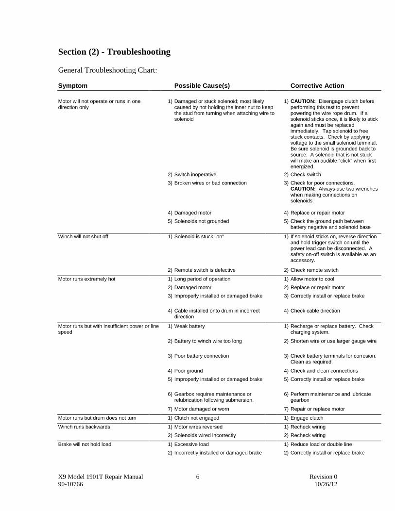
Symptom Possible Cause(s) Corrective Action
Motor will not operate or runs in one direction only
1) Damaged or stuck solenoid; most likely caused by not holding the inner nut to keep the stud from turning when attaching wire to solenoid
1) CAUTION: Disengage clutch before performing this test to prevent powering the wire rope drum. If a solenoid sticks once, it is likely to stick again and must be replaced immediately. Tap solenoid to free stuck contacts. Check by applying voltage to the small solenoid terminal. Be sure solenoid is grounded back to source. A solenoid that is not stuck will make an audible "click" when first energized.
2) Switch inoperative 2) Check switch
3) Broken wires or bad connection 3) Check for poor connections. CAUTION: Always use two wrenches when making connections on solenoids.
4) Damaged motor 4) Replace or repair motor
5) Solenoids not grounded 5) Check the ground path between battery negative and solenoid base
Winch will not shut off 1) Solenoid is stuck "on" 1) If solenoid sticks on, reverse direction and hold trigger switch on until the power lead can be disconnected. A safety on-off switch is available as an accessory.
2) Remote switch is defective 2) Check remote switch
Motor runs extremely hot 1) Long period of operation 1) Allow motor to cool
2) Damaged motor 2) Replace or repair motor
3) Improperly installed or damaged brake 3) Correctly install or replace brake
4) Cable installed onto drum in incorrect direction
4) Check cable direction
Motor runs but with insufficient power or line speed
1) Weak battery 1) Recharge or replace battery. Check charging system.
2) Battery to winch wire too long 2) Shorten wire or use larger gauge wire
3) Poor battery connection 3) Check battery terminals for corrosion. Clean as required.
4) Poor ground 4) Check and clean connections
5) Improperly installed or damaged brake 5) Correctly install or replace brake
6) Gearbox requires maintenance or relubrication following submersion.
6) Perform maintenance and lubricate gearbox
7) Motor damaged or worn 7) Repair or replace motor
Motor runs but drum does not turn 1) Clutch not engaged 1) Engage clutch
Winch runs backwards 1) Motor wires reversed 1) Recheck wiring
2) Solenoids wired incorrectly 2) Recheck wiring
Brake will not hold load 1) Excessive load 1) Reduce load or double line
2) Incorrectly installed or damaged brake 2) Correctly install or replace brake

X9 Model 1901T Repair Manual 7 Revision 0
90-10766 10/26/12
Visual Inspection. Before any troubleshooting beyond basic installation problems, always begin by inspecting the
winch and the installation visually.
WARNING! This is a 9000-pound winch. Any visible damage to components should be
considered just cause for replacing those components.
Check for visual damage to all external components, including:
Frayed or damaged wire rope or hook
Damage to fairlead
Cracks in gearbox cover
Bent tie bars
Bent drum flanges
Cracked or damaged drum support castings
Bent or broken freewheel knob
Bent or broken motor connections
Check that all hardware items are present and tight:
Tie rod bolts
Gearbox housing screws
Motor bolts
Mounting bolts
Electrical connections tight and not corroded
Check for any excessive noises coming from the winch:
Noise during freewheel of wire rope off the drum
Noise during operation
Refer to the appropriate section for troubleshooting and repair of conditions found. (See table of
contents at the front of this manual).
2.1 Winch does not rotate in either direction.
2.1.1 Check power source
Using a voltage or multi-meter, check the power source for voltage output. If voltage is less than
10 volts, repair or replace the power source. The winch will run at less than 12 volts but will not perform to
advertised specification unless the no load voltage is equal to or greater than 12.8 volts.
If power source is acceptable, proceed to 2.1.2
2.1.2 Check electrical connections
Examine visually for burnt or damaged connections, wires or other components.
Check the positive and negative connections to the battery or power source for a clean and
mechanically secure connection. Remove the (4) screws that secure the solenoid cover onto the solenoid
assembly and carefully place the cover to the side. Be careful not to damage the wires to the connector
assembly (see figure on top of next page).

X9 Model 1901T Repair Manual 8 Revision 0
90-10766 10/26/12
1901T Solenoid Cover removed showing solenoids and connections.
PZQ93 00010 / PZQ93 00030 KITS
Check the positive connection (to the solenoid assembly) and negative connection (to the winch motor) for
a clean and mechanically secure connection. Check the connections between the wire and the mechanical
connector (lug) for a clean and secure connection at the battery and winch motor and solenoid assembly.
Ensure there are no “broken” of frayed wire strands at the mechanical wire lug. Verify connections by
checking continuity and voltage drop using a voltage or multi-meter. All connections should have the same
voltage as the power source.
If connection or cables are corroded, disconnect the cables from the power source and clean
corrosion with a mixture of baking soda and water. Reattach cables to the battery. Using voltage or multi-
meter, verify the voltage is the same at the power source and the winch motor connection. Examine cables
for damage to the insulation jacket, which may cause an electrical short. If there is damage to the cable or a
voltage drop greater than 2 volts, replace the power leads.
If voltage is correct, proceed to 2.1.3
2.1.3 Check remote handle connection
Examine visually for burnt or damaged connections, wires or other components.
Visually examine the pins in the remote switch pendant cord. Verify there are three (3) pins in the
connector and the pins are not bent or damaged. Verify there are three (3) sockets in the connector
assembly on the solenoid cover assembly and the sockets are not bent or damaged. If there are damaged
pins in the pendant or solenoid cover socket, replace the pendant cord or socket assembly.
Using a voltage or multi-meter, check the voltage at the sockets in the connector assembly on the
solenoid cover assembly. The white wire on the connector assembly should have the same voltage as the
power source. If there is no voltage or reduced voltage on the white wire, check for damage to the white
wire or a poor connection to the solenoid bracket. Check the condition of the positive lead from the battery
to the solenoid assembly (see 2.1.2).
If the connector assembly is damaged or defective, replace it. If the remote switch pendant plug is
damaged or defective, replace it.
Using an ohmmeter, continuity tester or multi-meter, check the switch performance using the pins
on the remote switch plug. To check the forward operation of the switch, connect the meter to pin (W) and
pin (G). Put the switch in the forward position and activate the switch. If the meter does not indicate a
continuous circuit, or the meter indicates a continuous circuit when the switch is not activated, proceed to
2.1.4. To check the reverse operation of the switch, connect the meter to pin (W) and pin (B). Put the
switch in the reverse position and activate the switch. If the meter does not indicate a continuous circuit, or
the meter indicates a continuous circuit when the switch is not activated, proceed to 2.1.4.
If all tests are acceptable, proceed to 2.1.5.
2.1.4 Check remote switch
X9 Model 1901T Repair Manual 9 Revision 0
90-10766 10/26/12
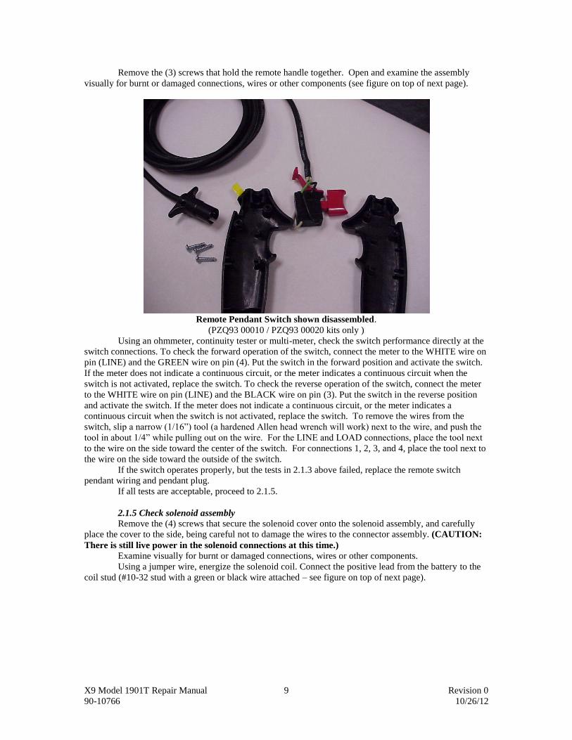
Remove the (3) screws that hold the remote handle together. Open and examine the assembly
visually for burnt or damaged connections, wires or other components (see figure on top of next page).
Remote Pendant Switch shown disassembled.
(PZQ93 00010 / PZQ93 00020 kits only )
Using an ohmmeter, continuity tester or multi-meter, check the switch performance directly at the
switch connections. To check the forward operation of the switch, connect the meter to the WHITE wire on
pin (LINE) and the GREEN wire on pin (4). Put the switch in the forward position and activate the switch.
If the meter does not indicate a continuous circuit, or the meter indicates a continuous circuit when the
switch is not activated, replace the switch. To check the reverse operation of the switch, connect the meter
to the WHITE wire on pin (LINE) and the BLACK wire on pin (3). Put the switch in the reverse position
and activate the switch. If the meter does not indicate a continuous circuit, or the meter indicates a
continuous circuit when the switch is not activated, replace the switch. To remove the wires from the
switch, slip a narrow (1/16”) tool (a hardened Allen head wrench will work) next to the wire, and push the
tool in about 1/4” while pulling out on the wire. For the LINE and LOAD connections, place the tool next
to the wire on the side toward the center of the switch. For connections 1, 2, 3, and 4, place the tool next to
the wire on the side toward the outside of the switch.
If the switch operates properly, but the tests in 2.1.3 above failed, replace the remote switch
pendant wiring and pendant plug.
If all tests are acceptable, proceed to 2.1.5.
2.1.5 Check solenoid assembly
Remove the (4) screws that secure the solenoid cover onto the solenoid assembly, and carefully
place the cover to the side, being careful not to damage the wires to the connector assembly. (CAUTION:
There is still live power in the solenoid connections at this time.)
Examine visually for burnt or damaged connections, wires or other components.
Using a jumper wire, energize the solenoid coil. Connect the positive lead from the battery to the
coil stud (#10-32 stud with a green or black wire attached – see figure on top of next page).

X9 Model 1901T Repair Manual 10 Revision 0
90-10766 10/26/12
1901T Solenoid Assembly showing coil studs and cables.
PZQ93 00010 / PZQ93 00030
An audible click should be heard if the solenoid is working properly. Connect a continuity tester or multi-
meter to the side terminals of the solenoid being tested. When the solenoid is activated, there should be
continuity across the two side terminals (5/16-18 copper studs).
Place the continuity tester or multi-meter across the bottom copper studs with the solenoid coil in
the “at rest” position. There should be continuity in the bottom studs.
If continuity is missing in either test, the solenoid is defective and must be replaced (See section
3). Both solenoids must pass both tests (at rest and actuation) or the solenoid is defective.
If both solenoids test acceptable, proceed to 2.1.6.
2.1.6 Check motor
Disconnect all leads to the motor.
Using an ohmmeter, check the resistance between F1 and F2 terminals. The reading should be
zero, or very close to zero, depending on scale used. Check the resistance between terminal F1 and the
motor body, and between terminal F2 and the motor body. The reading should be very high, or show
infinite resistance, depending on the ohmmeter and scale used.
Check the resistance between terminal A and the motor body. The reading should be zero or close
to zero. Readings in ohms or higher values means a damaged armature or commutator-brush system.
If available, check the insulation resistance with AC voltage up to 150V between terminal F1 or
F2 and the motor body. Test time is 1 minute. Motor should withstand test without insulator breakdown.
With these simple tests you can determine if the field windings are not broken or grounded to the
motor body, and that the insulation is not damaged beyond acceptable limits (if available).
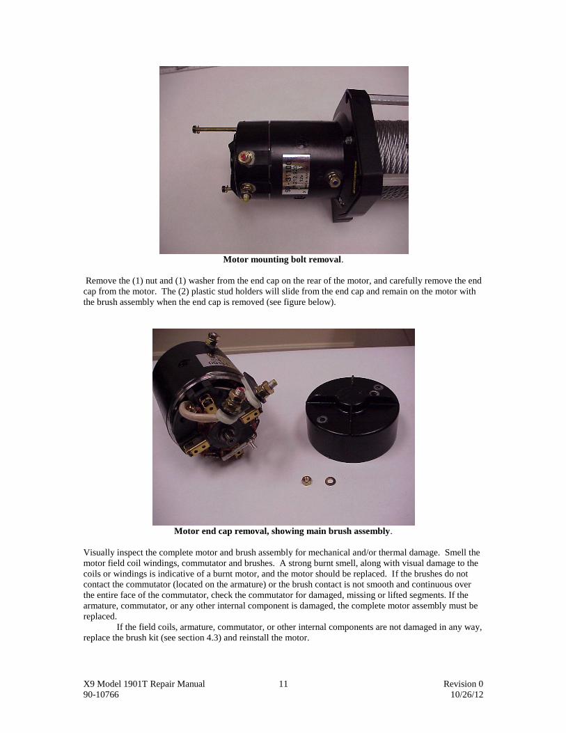
Remove the motor from the winch assembly by removing the (2) motor mounting bolts on the end
of the motor (see following figure). Use caution, when removing the motor from the adapter casting, to not
dislodge the armature from the motor and brush assembly.
X9 Model 1901T Repair Manual 11 Revision 0
90-10766 10/26/12
Motor mounting bolt removal.
Remove the (1) nut and (1) washer from the end cap on the rear of the motor, and carefully remove the end
cap from the motor. The (2) plastic stud holders will slide from the end cap and remain on the motor with
the brush assembly when the end cap is removed (see figure below).
Motor end cap removal, showing main brush assembly.
Visually inspect the complete motor and brush assembly for mechanical and/or thermal damage. Smell the
motor field coil windings, commutator and brushes. A strong burnt smell, along with visual damage to the
coils or windings is indicative of a burnt motor, and the motor should be replaced. If the brushes do not
contact the commutator (located on the armature) or the brush contact is not smooth and continuous over
the entire face of the commutator, check the commutator for damaged, missing or lifted segments. If the
armature, commutator, or any other internal component is damaged, the complete motor assembly must be
replaced.
If the field coils, armature, commutator, or other internal components are not damaged in any way,
replace the brush kit (see section 4.3) and reinstall the motor.
X9 Model 1901T Repair Manual 12 Revision 0
90-10766 10/26/12
2.2 Winch rotates in only one direction.
2.2.1 Check remote switch.
To check the remote switch and connections see sections 2.1.3 and 2.1.4.
2.2.2 Check solenoid assembly.
To check the solenoid assembly, see section 2.1.5.
2.2.3 Check motor.
To check the motor, see section 2.1.6.
2.3 Motor does not stop.
2.3.1 Check remote switch.
To check the remote switch and connections see sections 2.1.3 and 2.1.4.
2.3.2 Check solenoid assembly.
To check the solenoid assembly, see section 2.1.5.
2.4 Motor runs but drum does not turn.
2.4.1 Check free wheel mechanism
Actuate the free wheel knob to ensure it is in the “engaged” position. Observe the movement of
the knob. If operating properly, the knob should move into the gearbox housing when actuated into the
“engaged” position. If the knob does not move into engagement, rotate the drum by hand to check the
alignment of the free wheel lock pin to the lock pin holes in the ring gear. There are three (3) holes in the
ring gear for the free wheel lock pin to engage with in order to drive the drum.
If the knob moves inward but does not engage the gearbox, the gearbox needs to be disassembled
to troubleshoot. To disassemble the gearbox, remove the four (4) retaining screws from the gearbox
housing. Carefully work the housing away from the inboard drum support. Remove the two (2) ring gears
and the ring gear bearing from the housing. Examine the lock pin holes in the fixed ring gear for wear and
damage. Examine the free wheel lock pin for wear and damage. If either the ring gear or the lock pin show
signs of bending, rounding of the edges or exit and entry drag marks, both pieces must be replaced (see
section 5 for complete inspection, removal and repair instructions).
2.4.2 Check motor coupling
Remove the motor from the motor adapter by removing the two (2) motor mount bolts on the end
of the motor. Use caution when removing the motor from the adapter casting. Do not dislodge the armature
from the motor and brush assembly when removing.
Remove the motor adapter by removing the (3) bolts that hold the motor adapter to the support
casting. Grasp the coupling with needle nose pliers to remove it. Do a visual examination for cracks or
damage. If damaged, replace the coupling and reassemble the motor. Tighten the (3) motor adapter bolts to
45-50 in-lbs. Tighten the (2) motor mounting bolts to 45-50 in-lbs.
2.5 Winch runs with excessive noise.
2.5.1 Gearbox lubrication or damage
The gearbox and drum bearings are permanently lubricated with a high performance gear lube. If
relubrication is necessary (after repair or disassembly) only use factory approved grease (Superwinch Part
Number 90-15020). See section 6 for gearbox disassembly and maintenance.

X9 Model 1901T Repair Manual 13 Revision 0
90-10766 10/26/12
2.5.2 Check for other Damaged Components
Check for damage to the motor, brake, drum, and bearings. Refer to the appropriate section for
troubleshooting and repair
2.6 Winch runs slow.
2.6.1 Check power source and winch voltage. Using voltage or multi-meter, verify the voltage is the same at the power source and the winch
motor connection. (Reference Sections 2.1, 2.2, and 2.3.) If there is a voltage drop of greater than 2 volts,
replace the power leads.
2.6.2 Check current draw.
Refer to section 1 for current draw values of a properly operating winch. Higher than normal
current draw could mean that the winch is damaged, needs maintenance, or the motor is damaged. Perform
gearbox, brake, and motor inspection in the appropriate sections. Check to be sure wire rope is wound in
the proper direction around the drum, and the brake is installed in the proper orientation.
2.6.3 Check for Gearbox lubrication.
Refer to section 6 for gearbox inspection, removal, and relubrication.
2.7 Winch does not pull as expected
2.7.1 Check power source and winch voltage.
Using voltage or multi-meter, verify the voltage is the same at the power source and the winch
motor connection. (Reference Sections 2.1, 2.2, and 2.3.) If there is a voltage drop of greater than 2 volts,
replace the power leads.
2.7.2 Check Current draw
Refer to section 1 for current draw values of a properly operating winch. Higher than normal
current draw could mean that the winch is damaged, needs maintenance, or the motor is damaged. Perform
gearbox, brake, and motor inspection in the appropriate sections. Check to be sure wire rope is wound in
the proper direction around the drum, and the brake is installed in the proper orientation (see section 7).
2.7.3 Check for Gearbox lubrication.
Refer to section 6 for gearbox inspection, removal, and relubrication.
2.8 Freewheel operation troubleshooting
2.8.1 Freewheel is difficult to engage and / or disengage
Refer to section 2.4.1 for freewheel troubleshooting.
2.8.2 Freewheel will not engage
Refer to section 2.4.1 for freewheel troubleshooting.
2.8.3 Freewheel will not disengage
Refer to section 2.4.1 for freewheel troubleshooting.
2.8.4 Drum will not rotate freely when freewheel is disengaged.
Do a visual inspection of the winch assembly and mounting points checking for loose hardware
and damaged components. Ensure the mounting bolts are tightened properly and the mounting feet are
undamaged. If mounting locations are loose, continue checking for other loose hardware and damaged

X9 Model 1901T Repair Manual 14 Revision 0
90-10766 10/26/12
components before retightening the mounting feet. If the mounting castings are damaged, replace the
castings before proceeding.
Visually check for damage to the drum flanges that may be dragging on the drum support castings.
If contact between the drum support casting and drum flange is evident by scratches in the supports or
noise during free wheel operation, disassemble the winch for further analysis.
Remove the motor by removing the (2) motor mounting screws on the end of the motor, and then
motor adapter plate by removing the three (3) adapter plate mounting screws. Remove the two (2) tie rod
bolts and remove the drum support. Remove the drum.
Examine the (2) drum bearings, and the thrust washer between the drum and the inboard support.
If the bearings or thrust washer show signs of wear or damage, replace the components. (Note: The
gearbox needs to be removed to change the inboard drum support bearing. See section 6.)
Examine the drum flanges and drum support castings for damage. Examine the castings; evaluate
any damage that occurred from contact with the drum. If the castings show signs of contact, determine their
fitness for use.
WARNING! This is a 9000-pound winch. Any damage to the castings should be
considered just cause for replacing the damaged components.
Determine the cause of the damage before reassembling the winch. If the drum flanges are bent,
they must be straightened to total run-out of less than .040 inches per flange or the drum must be replaced
Ensure the tie rods are straight, tightened properly and undamaged. The tie rods are held place
with 1/4-20 socket head cap screws (SHCS) tensioned to 75-80 in-lbs. Before tightening the tie rods,
ensure the mounting bolts are loose or damage to the castings will occur. If the tie rods are bent, damaged
or have heavy marks from the cable dragging against them, they must be replaced. Torque the tie rod bolts
properly. After the tie rods are properly installed, torque the mounting bolts to 30-35 ft-lbs.
2.8.5 Drum rotates too freely when freewheel is disengaged (cable unravels). Do a visual inspection of the winch assembly and mounting points checking for loose hardware
and damaged components. Ensure the mounting bolts are tightened properly and the mounting feet are
undamaged. If mounting locations are loose, continue checking for other loose hardware and damaged
components before retightening the mounting feet. If the mounting castings are damaged, replace the
castings before proceeding.
Visually check for damage to the drum flanges. If contact between the drum support casting and
drum flange is evident by scratches in the supports or noise during free wheel operation, disassemble the
winch for further analysis.
Remove the motor by removing the (2) motor mounting screws on the end of the motor, and then
motor adapter plate by removing the three (3) adapter plate mounting screws. Remove the two (2) tie rod
bolts and remove the drum support. Remove the drum.
Examine the (2) drum bearings, and the thrust washer between the drum and the inboard support.
If the bearings or thrust washer show signs of wear or damage, replace the components. (Note: The
gearbox needs to be removed to change the inboard drum support bearing. See section 6.)
Examine the drum flanges and drum support castings for damage. Examine the castings; evaluate
any damage that occurred from contact with the drum. If the castings show signs of contact, determine their
fitness for use.
WARNING! This is a 9000-pound winch. Any damage to the castings should be
considered just cause for replacing the damaged components.
Check the drum drag button and drag button spring. If the drag button or drag button spring shows
signs of wear or damage, replace the components. Once the drag button and spring are replaced, reassembly
the winch. Determine the cause of the damage before reassembling the winch. If the drum flanges are bent,
they must be straightened to total run-out of less than .040 inches per flange or the drum must be replaced

X9 Model 1901T Repair Manual 15 Revision 0
90-10766 10/26/12
Ensure the tie rods are straight, tightened properly and undamaged. The tie rods are held place
with 1/4-20 socket head cap screws (SHCS) tensioned to 75-80 in-lbs. Before tightening the tie rods,
ensure the mounting bolts are loose or damage to the castings will occur. If the tie rods are bent, damaged
or have heavy marks from the cable dragging against them, they must be replaced. Torque the tie rod bolts
properly. After the tie rods are properly installed, torque the mounting bolts to 30-35 lbs-ft.

X9 Model 1901T Repair Manual 16 Revision 0
90-10766 10/26/12
Section (3) – Electrical and Solenoids
3.1 Inspection and Troubleshooting See sections 2.1, 2.2, and 2.3
3.2 Solenoid Removal and Replacement
WARNING! ALWAYS disconnect the main power source when working on the Solenoid
Assembly, otherwise serious personal injury could result.
CAUTION! When working on the Solenoid Assembly, ALWAYS use an open-end wrench
or spanner to hold the inner nut while making connections, otherwise damage to the
solenoid will occur. Failure to use an open-end wrench or spanner on the inner nut
will void the warranty.
To replace a solenoid in the solenoid assembly, be sure to note the position of the wires and cables
before disassembly (see figure below as a guide).
Solenoid Wiring.
Unbolt the solenoid from the assembly, and replace it with a new solenoid. Be sure to always use an open-
end wrench to hold the inner nut on ALL solenoid connections when re-connecting the cables or damage to
the solenoid will occur.

X9 Model 1901T Repair Manual 17 Revision 0
90-10766 10/26/12
3.3 Solenoid Cover Socket Removal and Replacement To replace the socket assembly on the solenoid cover, disconnect the (3) wires on the solenoid
assembly, and remove the (2) screws and (2) nuts holding the connector/wire assembly to the solenoid
cover (see figure below).
Solenoid Cover Socket Removal.
( old style socket PZQ93 00010 )
Mount the new socket/wire assembly on the solenoid cover and connect the wires to the solenoid assembly.

X9 Model 1901T Repair Manual 18 Revision 0
90-10766 10/26/12
Section (4) - Motor
4.1 Troubleshooting
For troubleshooting the entire electrical system including the motor see section 2. Always be sure
the entire electrical system is in proper repair and the power source is delivering the proper level of power
before investigating performance-related problems at the motor.
4.1.1 Excess Noise
If the motor is operating with excess noise, it is likely the result of wear or damage to the internal
components of the motor or gearbox. Proceed to 4.2 to remove the motor for further investigation.
4.1.2 Current draw
Refer to section 1 for current draw values of a properly operating winch.
4.1.3 Performance
The 12V motor is a 2.3 hp (1.7 kW) peak series wound motor. Performance figures and line
speeds can be found in section 1. If the winch appears to be operating slowly, refer to the troubleshooting
section in Section 2.
4.1.4 Motor runs in only one direction
See troubleshooting in Section 2
4.2 Inspection and Removal
Disconnect all leads to the motor.
Using an ohmmeter, check the resistance between F1 and F2 terminals. The reading should be
zero, or very close to zero, depending on scale used. Check the resistance between terminal F1 and the
motor body, and between terminal F2 and the motor body. The reading should be very high, or show
infinite resistance, depending on the ohmmeter and scale used.
Check the resistance between terminal A and the motor body. The reading should be zero or close
to zero. Readings in ohms or higher values means a damaged armature or commutator-brush system.
If available, check the insulation resistance with AC voltage up to 150V between terminal F1 or
F2 and the motor body. Test time is 1 minute. Motor should withstand test without insulator breakdown.
With these simple tests you can determine if the field windings are not broken or grounded to the
motor body, and that the insulation is not damaged beyond acceptable limits (if available).
Remove the motor from the winch assembly by removing the (2) motor mounting bolts on the end
of the motor (see following figure). Use caution when removing the motor from the adapter casting, to not
dislodge the armature from the motor and brush assembly.

X9 Model 1901T Repair Manual 19 Revision 0
90-10766 10/26/12
Motor mounting bolt removal.
Remove the (1) nut and (1) washer from the end cap on the rear of the motor, and carefully
remove the end cap from the motor. The (2) plastic stud holders will slide from the end cap and remain on
the motor with the brush assembly when the end cap is removed (see figure below).
Motor end cap removal, showing main brush assembly.
Visually inspect the complete motor and brush assembly for mechanical and/or thermal damage.
Smell the motor field coil windings, commutator and brushes. A strong burnt smell, along with visual
damage to the coils or windings is indicative of a burnt motor, and the motor should be replaced. If the
brushes do not contact the commutator (located on the armature) or the brush contact is not smooth and
continuous over the entire face of the commutator, check the commutator for damaged, missing or lifted
segments. If the armature, commutator, or any other internal component is damaged, the complete motor
assembly must be replaced.
If the field coils, armature, commutator, or other internal components are not damaged in any way,
replace the brush kit (see section 4.3) and reinstall the motor.

X9 Model 1901T Repair Manual 20 Revision 0
90-10766 10/26/12
4.3 Repair (Note: Brush replacement is the only motor repair that is recommended by Superwinch. Any and
all other motor damage or wear means that the motor assembly must be replaced.)
4.3.1 Brush Replacement.
Remove the motor as described in section 4.2.
Remove the end cap from the motor exposing the main brush assembly as described in section 4.2.
Remove the main brush assembly from the end of the armature.
There are (4) brush/spring assemblies on the main brush assembly. Each brush/spring assembly is
held to the main brush assembly by (1) screw. Each brush/spring assembly slides to the center of the brush
assembly for removal. Remove and replace the spring/brush assemblies one at a time (see figures below).
Main Brush Assembly – Brush Replacement.
Slide brush towards center.
Pivot brush up.
Remove screw and remove brush.
Reassembly is the reverse of removal. Tighten the (2) motor mounting bolts to 45-50 in-lbs.
X9 Model 1901T Repair Manual 21 Revision 0
90-10766 10/26/12
Section (5) - Gearbox
5.1 Troubleshooting If the gearbox is noisy in operation, it is likely worn or damaged, and should be disassembled for
inspection. If the vehicle sees water crossings regularly where the winch is completely submerged, it is
recommended that the gearbox be disassembled after each outing during which the winch was submerged,
or on a regular basis, for inspection, cleaning and relubrication. Use only genuine Superwinch grease (P/N
90-15020) to relubricate the winch. See section 5.2 for the removal, inspection, and relubrication process.
The freewheel knob should move smoothly in and out. If the freewheel knob does not move
freely and function properly, the gearbox should be disassembled and the damaged or worn parts replaced.
See section 5.2.
5.2 Inspection, Removal, and Repair Visually inspect the gearbox end of the winch for housing damage, cracks, and broken or dented
parts. Any parts visibly damaged must be replaced.
To disassemble the gearbox, remove the four (4) retaining screws from the gearbox housing.
Carefully work the housing away from the inboard drum support.
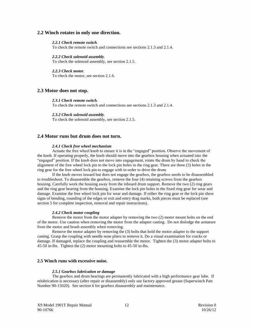
Remove the two (2) ring gears and the ring gear bearing (see figure below).
Gearbox disassembly.
Examine the (3) lock pin holes in the fixed ring gear for wear and damage. If the lock pin holes
show signs of bending, rounding of the edges or exit and entry drag marks, the fixed ring gear must be
replaced.
Examine the ring gear bearing for wear and damage. If the ring gear bearing shows signs of wear
replace the bearing.
Examine the gearbox bushing that pilots on the inside of the gearbox housing for wear. Replace if
necessary.
Remove the free wheel knob by removing the knob retention screw (#T20 Torx screw) and
remove the lock pin and lock pin spring from the housing (see figure below).

X9 Model 1901T Repair Manual 22 Revision 0
90-10766 10/26/12
Freewheel knob and lock pin removal.
If the lock pin shows any signs of wear, bending or damage, replace the lock pin. Check the compression
spring for damage, and replace the spring if necessary.
Examine the gearbox housing for damage in the lock pin diameter. If the lock pin hole is stretched
or ovaled, or cracking is evident in the outer edge of the casting, replace the casting and the lock pin.
Lightly coat all parts with Superwinch grease (P/N 90-15020) upon assembly of the lock pin. NOTE:
When installing the freewheel knob, be sure to check that the flat on the locking pin where the knob mounts
is aligned to the flat inside the freewheel knob, otherwise the knob will not tighten down fully to the lock
pin, and the winch will not freewheel. The lock pin mechanism should operate smoothly.
Check the installation of the lock pin by activating it and looking inside the housing. The lock pin
should be completely below the surface on the inside of the gearbox housing. If the end of the lock pin is
not completely below the surface on the inside of the gearbox housing, the freewheel knob is not installed
properly, as noted above.
Remove the planet assembly and carrier bushing by removing it from the end of the drive shaft
(see gearbox disassembly figure above).
Examine the planet carrier assembly for damage to the planet gears or carrier housing. Each
planet gear should rotate smoothly on its shaft with no noticeable slop. If the planet carrier assembly shows
any signs of excessive wear or damage, the entire assembly must be replaced.
Examine the carrier bushing for signs of wear. If the carrier bushing is damaged or shows signs of
excessive wear it must be replaced.
Examine the sun gear, which is a part of the drive shaft that is still in the winch. If the sun gear
shows signs of damage or excessive wear, the drive shaft must be replaced.
To replace the drive shaft, remove the motor, motor adapter, drive shaft coupling, and the (2)
thrust washers from the drive shaft, all from the opposite (motor) end of the winch (see section X). Then
remove the drive shaft from the gearbox end of the winch. The drive shaft can only be removed from the
gearbox end of the winch unless the brake is removed from the drum.
Reassembly is the opposite of removal. During reassembly, all mating parts are to be coated
lightly with Superwinch grease part # 90-15020. Completely fill the teeth of the (2) ring gears and the (3)
planet gears with Superwinch grease (P/N 90-15020). Torque the gearbox housing bolts to 45-50 in-lbs.

X9 Model 1901T Repair Manual 23 Revision 0
90-10766 10/26/12
Section (6) - Brake
6.1 Troubleshooting.
The winch is supplied with an internal drag brake that stops and holds loads up to 4,500 lbs. (2041
kg) on the first layer of wire rope closest to the drum. Each additional layer of wire rope reduces brake
capacity approximately 10%. The brake is disengaged when the winch is powering in, and does not
become activated until the motor is turned off and the load tries to pull the wire rope off the drum. When
the winch is powered out, as in releasing a load, the brake is engaged and the motor must overpower the
brake drag to rotate the drum. Therefore, it is normal for the winch to operate faster in one direction than
the other. The brake is also designed for the wire rope to be used in the underwound position only – DO
NOT OVERWIND THE WIRE ROPE (see section 7). If it is suspected that the brake is not operating
properly, be sure to check that the wire rope is wound properly onto the drum (see section 7).
To troubleshoot the brake it will need to be removed from the winch for inspection. If the brake is
worn, it will need to be replaced. The brake assembly is not field serviceable.
6.2 Brake Removal.
Remove the motor by removing the (2) screws on the end of the motor (see section 2.1.6)
Remove the motor adapter assembly by removing the (3) screws that hold the adapter to the drum
support casting.
Remove the drive shaft coupling.
Loosen the winch mounting bolts if the winch is mounted and this has not already been done, and
remove the mounting bolts from the outboard drum support casting.
Remove the (2) screws that hold the tie bars to the outboard drum support casting and remove the
outboard drum support casting. Use care to not drop the drum drag button and drag button spring. Use
care to support the remainder of the winch so that no damage occurs to the remaining assembly.
Remove the drive shaft, the (2) thrust washers, and the brake assembly from the inside of the
winch drum (see figure below).
Brake and drive shaft removal shown from MOTOR end of the winch.
( ** Note new style brake is shorter than that shown ** )
Remove the brake assembly from the drive shaft.

X9 Model 1901T Repair Manual 24 Revision 0
90-10766 10/26/12
6.3 Inspection.
There should be no contamination in the form of water, mud, grease, etc, inside the drum, or on
the drive shaft or the brake. If the brake is contaminated with grease or other foreign material, the brake
unit must be replaced. Clean any contamination present from the drum and driveshaft before the new brake
assembly is installed.
If the brake is not contaminated, inspect it for wear. There must be spring force on the brake pads
when the brake is installed in the drum. If the brake is worn to the point that there is no spring force on the
pads when the brake is installed in the drum, it must be replaced. With the brake installed in the drum, use
the end of the brake assembly as a gauge to measure brake wear. The slots in the brake pad retainer can be
used as a wear gauge. A new pad will have a large amount of brake pad stroke remaining (see figure
below).
New brake pad Worn brake pad
Any brake with less than approximately 1/16” of stroke remaining should be replaced.
6.4 Installation.
Install the new brake assembly onto the drive shaft (the brake assembly must be installed in the
correct orientation - see figure below).
Brake installation shown from the MOTOR end of the winch.

X9 Model 1901T Repair Manual 25 Revision 0
90-10766 10/26/12
Reinstall the drive shaft and brake assembly into the winch drum. Reinstall the (2) thrust washers
and the outboard drum support. Use care installing the drum support and watch that the drum drag button
and spring are installed correctly and are against the drum. Torque the tie bar screws to 75-80 in-lbs.
Reinstall the drive shaft coupling, motor adapter, and motor. Torque the (3) motor adapter bolts and the (2)
motor mounting bolts to 45-50 in-lbs.

X9 Model 1901T Repair Manual 26 Revision 0
90-10766 10/26/12
Section (7) – Wire Rope, Fairlead, and Hook.
7.1 Wire Rope.
7.1.1 Inspection
The wire rope should be inspected periodically for kinks and other damage. Any kinks, broken
strands, or visible damage to the wire rope means that it must be replaced immediately. NEVER use
a winch with a damaged wire rope.
Always replace the wire rope with a genuine Superwinch replacement part. (See Owner’s Manual
for Parts List).
Never substitute a heavier or lighter wire rope, or a rope made of any material other than wire.
7.1.2 Removal and Replacement
Freewheel all of the existing wire rope off of the winch. Loosen the set screw on the drum, and
remove the wire rope. Inspect the set screw and drum for any visible damage, and replace any damaged
parts before installing a new wire rope.
Upon installation, the wire rope must be wound on the drum in the proper direction (see figure
below), called UNDERWOUND, for the brake to operate properly. DO NOT WIND THE WIRE ROPE
IN THE OVERWIND POSITION. The drum must turn clockwise, looking from the motor end, when
winching in.
Wire rope properly installed in UNDERWOUND position
(shown from MOTOR end of winch).
Insert the new wire rope into the correct hole and tighten the set screw on the drum securely. It is
important that the new wire rope be wound tightly onto the drum. One way to do this is to attach the wire
rope hook to a fixed object at the top of a slight incline, then winch the vehicle up the incline as the rope is
wound onto the drum.
7.2 Fairlead.
7.2.1 Inspection
X9 Model 1901T Repair Manual 27 Revision 0
90-10766 10/26/12
If the winch has a roller fairlead, inspect all (4) rollers. All (4) rollers should rotate easily. If there
are any rollers that show signs of grooves or bending, the roller fairlead should be replaced. If a roller is
not rotating, but does not show signs of grooves, excessive wear, or bending, the roller can be removed, any
corrosion or dirt removed, and Superwinch grease #90-15020 applied to the rotating bushing area. Remove
the roller by removing the (2) socket head cap screws attaching the roller to the fairlead frame. A roller
fairlead with frozen rollers could damage the wire rope and/or the roller. If the fairlead has
damaged rollers, the entire fairlead must be replaced.
7.2.2 Removal and replacement
To replace a fairlead, the hook must be removed from the end of the wire rope. To remove the
hook, simply bend the cotter pin, remove the hook pin, and remove the hook. On the roller fairlead, one of
the horizontal rollers must be unbolted for the end of the wire rope to pass through the fairlead. Unbolt the
fairlead from the winch mount or frame, and remove the fairlead. Installation is the reverse of removal.
Superwinch recommends always using a new cotter pin on the winch hook upon reassembly.
7.3 Hook.
7.3.1 Inspection
Inspect the winch hook for signs of cracks or severe wear. Any hook showing signs of damage or
excessive wear should be replaced immediately.
7.3.2 Removal and replacement.
To remove the hook from the end of the wire rope, bend the cotter pin and remove it from the
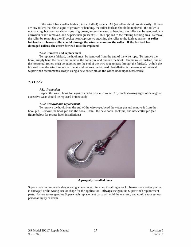
hook pin. Remove the hook pin and the hook. Install the new hook, hook pin, and new cotter pin (see
figure below for proper hook installation.)
A properly installed hook.
Superwinch recommends always using a new cotter pin when installing a hook. Never use a cotter pin that
is damaged or the wrong size or shape for the application. Always use genuine Superwinch replacement
parts. Failure to use genuine Superwinch replacement parts will void the warranty and could cause serious
personal injury or death.

X9 Model 1901T Repair Manual 28 Revision 0
90-10766 10/26/12
Section (8) – Exploded Views and Replacement Parts List Winch Assembly
X9 Model 1901T Repair Manual 29 Revision 0
90-10766 10/26/12
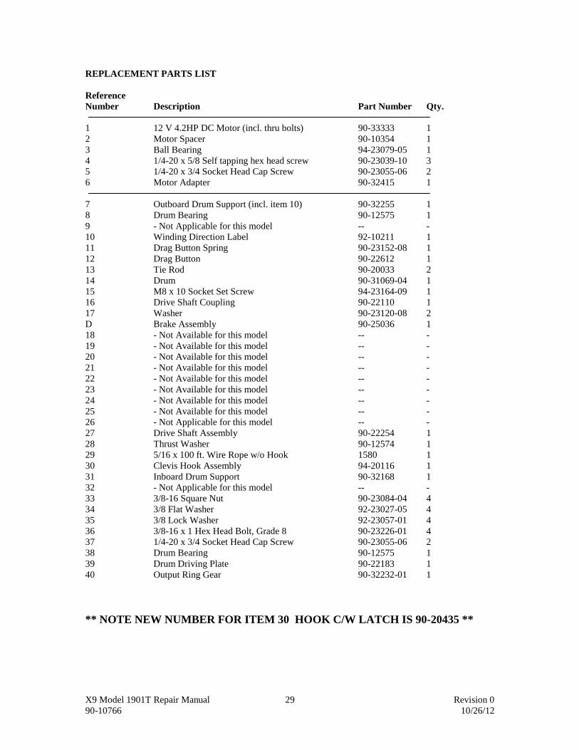
REPLACEMENT PARTS LIST
Reference
Number Description Part Number Qty.
1 12 V 4.2HP DC Motor (incl. thru bolts) 90-33333 1
2 Motor Spacer 90-10354 1
3 Ball Bearing 94-23079-05 1
4 1/4-20 x 5/8 Self tapping hex head screw 90-23039-10 3
5 1/4-20 x 3/4 Socket Head Cap Screw 90-23055-06 2
6 Motor Adapter 90-32415 1
7 Outboard Drum Support (incl. item 10) 90-32255 1
8 Drum Bearing 90-12575 1
9 - Not Applicable for this model -- -
10 Winding Direction Label 92-10211 1
11 Drag Button Spring 90-23152-08 1
12 Drag Button 90-22612 1
13 Tie Rod 90-20033 2
14 Drum 90-31069-04 1
15 M8 x 10 Socket Set Screw 94-23164-09 1
16 Drive Shaft Coupling 90-22110 1
17 Washer 90-23120-08 2
D Brake Assembly 90-25036 1
18 - Not Available for this model -- -
19 - Not Available for this model -- -
20 - Not Available for this model -- -
21 - Not Available for this model -- -
22 - Not Available for this model -- -
23 - Not Available for this model -- -
24 - Not Available for this model -- -
25 - Not Available for this model -- -
26 - Not Applicable for this model -- -
27 Drive Shaft Assembly 90-22254 1
28 Thrust Washer 90-12574 1
29 5/16 x 100 ft. Wire Rope w/o Hook 1580 1
30 Clevis Hook Assembly 94-20116 1
31 Inboard Drum Support 90-32168 1
32 - Not Applicable for this model -- -
33 3/8-16 Square Nut 90-23084-04 4
34 3/8 Flat Washer 92-23027-05 4
35 3/8 Lock Washer 92-23057-01 4
36 3/8-16 x 1 Hex Head Bolt, Grade 8 90-23226-01 4
37 1/4-20 x 3/4 Socket Head Cap Screw 90-23055-06 2
38 Drum Bearing 90-12575 1
39 Drum Driving Plate 90-22183 1
40 Output Ring Gear 90-32232-01 1
** NOTE NEW NUMBER FOR ITEM 30 HOOK C/W LATCH IS 90-20435 **

X9 Model 1901T Repair Manual 30 Revision 0
90-10766 10/26/12
REPLACEMENT PARTS LIST (CONT’D.)
Reference
Number Description Part Number Qty.
41 Ring Gear Bearing 90-22607 1
42 Carrier Bushing 90-10417 1
43 Planet Carrier Assembly 90-32238 1
44 Gearbox Bushing 90-10418 1
45 Plastic Closure 90-23171-05 2
46 8/32 x 3/8 Pan Head Screw 90-23032-17 1
47 - Not Applicable for this model -- -
48 - Not Applicable for this model -- -
49 Fixed Ring Gear 90-32233-01 1
50 Lock Pin 90-22252-01 1
51 Gearbox Housing (w/ 52, 56-58, 60
specify model no. when ordering) 90-32256 1
52 Warning/Clutch Operation Label
(specify model no.) 90-22263 1
53 1/4-20 x 5/8 Self Tapping Hex Head Screw 90-23039-10 4
54 Clutch Lever 90-32248 1
55 #8 Int. Tooth Lock Washer 90-23048-03 1
56 Dust Cover 90-22103 1
57 Plug 90-23171-07 1
58 Rubber Washer 92-10194 2
59 Clutch Spring 90-23152-07 1
60 Push-On Retainer 90-23213-04 2
61 2 AWG x 20” Lead Wire Assembly (Blue) 90-22635-25 1
62 2 AWG x 20” Lead Wire Assembly (Yellow) 90-22635-26 1
63 2 AWG x 20” Lead Wire Assembly (Red) 90-22635-27 1
64 10 AWG x 24” Lead Wire Assembly 90-22635-33 1
65 2 AWG x 72” Lead Wire Assembly (Yellow) 90-22635-08 1
66 2 AWG x 72” Lead Wire Assembly (Red) 90-22695-05 1
67 2 AWG Boot Terminal 90-23247-04 3
68 Handsaver 89-32300 1
NS 7” Long Wire Tie 94-23058-04 6
NS Grease (for one relube) 90-15020 1
NS Motor Brush Repair Kit 90-10414-05 1
ACC Roller Fairlead 2549 1
ACC Pulley Block, 20,000 lbs. 7750A 1
ACC Circuit Breaker Kit – 12 V 2232 1
ACC Circuit Breaker Kit – 24 V 2232A 1
NS – Not shown
ACC - Accessory

X9 Model 1901T Repair Manual 31 Revision 0
90-10766 10/26/12
1901T (PZQ93 00010 & PZQ93 00030) SOLENOID ASSEMBLY
Reference
Number Description Part Number Qty.
70 Remote Switch Pendant 90-22117 1
70 RUBBER Body Pendant Control ( see insert ) 2272 1
( suit PZQ93 0030 & PZQ93 00040 )
71 Reversing Switch (suit 90-22117 pendant only) 90-32007 1
71 Toggle Switch ( suit 2270 Pendant only) Not Shown 90-14141 1
72 #8-32 x 5/8 Screw 90-23032-03 2
73 Connector Assembly w/ Wires (PZQ93 00010 only) 90-22115 1
73 Connector Assembly w/Wires ( PZQ93 00030) 90-14140 1
74 Solenoid Cover (w/ Logo) 90-32187 1
75 #8-32 Hex Flange Nut 90-23149-06 2
76 - Not Applicable for this model -- -
77 12 VDC Solenoid 92-20172 2
78 Top Bus Bar 92-12383 1
79 8-32 x 1/2 Self Tapping Screw 92-23039-01 4
80 5/16-18 Hex Nut 92-23034-04 1
81 5/16 Lock Washer 92-23057-03 1
82 Front Buss Bar w/ Stud 92-12384 1
83 Solenoid Bracket 94-20118 1
84 10-32 Flange Nut 90-23149-01 4
85 Solenoid Base Plate w/ Studs 90-22627-02 1
86 1/4-20 x 3/4 Bolt Not applicable this model 90-23226-10 4
87 1/4-20 Hex Flange Nut Not applicable this model 90-23149-02 4
88 Solenoid Pack Bracket Not applicable this model 90-31027-02 1
89 10-32 x 1/2 Machine Screw 92-23125-01 2
90 Buss Bar #1 92-20126 1
91 1/4 Lock Washer Not applicable this model 90-23227-02 2
NS X9 Logo 90-20065 1
NS Control Pack X9 12V ( Pre-wired TMCA spec) 90-32395 1

X9 Model 1901T Repair Manual 32 Revision 0
90-10766 10/26/12
1901TA (PZQ93 00020 & PZQ93 00040) OPTIONAL HEAVY DUTY SOLENOID ASSEMBLY
Reference
Number Description Part Number Qty.
1 Remote Socket Cable Assembly (PZQ93 00020) 90-20364 1
1 Remote Socket Cable Assembly (PZQ93 00040) 90-25059 1
2 Solenoid 90-14452 1
3 Lead Wire Assy, #10 x 36”, Blk. 90-23330-04 1
4 Boot, Terminal, 2 GA 90-23247-04 4
5 Lead Wire Assy, 2 GA x 72”, Red 90-22695-28 1
6 Lead Wire Assy, 2 GA x 20”, Red 90-22635-27 1
7 Lead Wire Assy, 2 GA x 20”, Yellow 90-22635-26 1
8 Lead Wire Assy, 2 GA x 20”, Blue 90-22635-25 1
9 Spacer 94-23293-03 2
10 Screw, Hex Head M8 x 1.25 x 35 MM 94-23239-04 2
11 Washer, Lock, Hel. Spring 5/16 92-23057-03 2
12 Lockwasher (supplied with solenoid)
13 Nut (supplied with solenoid)
14 Screw, Hex Head (supplied with solenoid)
15 Cable Tie, 6 in. x .080 92-23058-01 1
A Complete Solenoid Assy (PZQ93 00020) 2269T 1
A Complete Solenoid Assy (PZQ93 00040) 90-40233 1
LIST OF TOYOTA PART NUMBERS
90-40233 PZQ93 00040SS
90-33333 PZQ93 001001 90-22117 PZQ93 0001070
1580 PZQ93 0001029 92-20172 PZQ93 0001077
94-20116 PZQ93 0001030 90-32395 PZQ93 00010PW
90-32248 PZQ93 0001054 Includes screw & washer 2269T PZQ93 00020SS
90-10414-01 PZQ93 00010CB 2272 PZQ93 0003070
90-10414-05 PZQ93 00010IB 2549 PZQ93 00030RF
90-14452 PZQ9300041SS (solenoid only) 90-20435 PZQ930001035

X9 Model 1901T Repair Manual 33 Revision 0
90-10766 10/26/12
![Corel VideoStudio Ultimate X9 Reviewer's Guidehelp.corel.com/videostudio/v19/main/en/rg/videostudio-x9-reviewers... · Corel VideoStudio Ultimate X9 Reviewer’s Guide [ i ] ... •](https://img.dokumen.tips/doc/110x75/5b0a0feb7f8b9ac7678bc60d/corel-videostudio-ultimate-x9-reviewers-videostudio-ultimate-x9-reviewers-guide.jpg)