Embed Size (px)
Citation preview

7/29/2019 X Radiography
http://slidepdf.com/reader/full/x-radiography 1/16
Guidelines on the
X-radiography of archaeological metalwork
2006
:

7/29/2019 X Radiography
http://slidepdf.com/reader/full/x-radiography 2/16
2
Contents
1 Introduction . . . . . . . . . . . . . . . 3
2 Why X-radiography
is necessary . . . . . . . . . . . . . . . . 3
3 When to X-ray . . . . . . . . . . . . . 4
4 What to X-ray . . . . . . . . . . . . . . 5
5 What X-radiography
can show . . . . . . . . . . . . . . . . . . 5
6 How to make informative
X-radiographs . . . . . . . . . . . . .10
7 How to view the
X-radiographs . . . . . . . . . . . . . 13
8 How much should it cost? . . . 13
9 Where to get help . . . . . . . . . . 14
Preface
Archaeological investigations frequently
yield numerous metal finds.These should
be X-rayed as part of the post-excavation
procedures to assist in the identification
and interpretation of the finds, and
thereby help understand the site.Thisprocedure will also provide a record of the
finds in the conditions in which they were
recovered.
Government policy on planning issues in
archaeology is stated in Planning Policy
Guidance Notes PPG 15 (Department of
the Environment 1994) and PPG 16
(Department of the Environment 1990).
These documents provide guidance to
local authorities and others who are
required to make planning decisions and
to prepare development plans. Local
authority planning archaeologists arerequired to advise on archaeological
aspects of the planning decisions and
briefs, of which the X-radiography of
archaeological metalwork forms a part.
These guidelines on the X-radiography of
archaeological metalwork advise on good
practice, including when to schedule the
work and when to cost for it.They will be
useful to local authority planning
archaeologists when providing advice or
briefs, to field project directors writing
specifications, and to managers over-
seeing excavation or post-excavation
projects.The guidelines will also be useful
to anyone directly involved with finds
work, whether recording, conserving,
researching or curating finds from
evaluations, excavations, museum
collections or the Portable Antiquities
Scheme.
Within the next few years there will be
advances in digital imaging and this willaffect our expectations and output of any
X-radiography programme. Although
these guidelines give advice on good
practice in the production of an ‘X-ray
archive’ using conventional film
X-radiography, they should not restrict
the development of additional or different
systems of archiving in the future.
These guidelines concentrate on the
X-radiography of archaeological
metalwork, which is one of the principal
material categories to benefit from its use,
providing a record of the material andassisting in a range of investigations and
classification. Other archaeological
materials are commonly X-rayed for a
variety of reasons, such as the study of
bone pathologies and analysis of soil
sediments, but it is beyond the scope of
this brief document to discuss these other
investigations in detail, although reference
to them is made where appropriate.
Equally, other more specialised methods
of radiography, using different techniques
(such as micro-focus or stereo) or
different ionizing radiations (such as
gamma rays) are not covered here and so
all references to radiography relate only to
the use of X-rays.
:

7/29/2019 X Radiography
http://slidepdf.com/reader/full/x-radiography 3/16
information that cannot be
gained by any other method.
Technological details can be
revealed without the need for
interventions. In addition, the
X-radiograph itself provides
a long-term visual record of
inherently unstable andpotentially deteriorating
artefacts.While much can be
done to slow down the
deterioration processes of
metal artefacts following their
removal from burial,
X-radiography should be
initiated as soon after
excavation as is practicable.
A good quality X-radiograph
may provide the information
necessary to identify, classify,
date and illustrate an object that has
subsequently disintegrated beyondreconstruction.
X-radiographs of metalwork are an
essential component of the site archive
(English Heritage 1991, 30, A3.1.1)
and, where necessary, the research
archive (English Heritage 1991, 37,
A6.1.1) and are a requirement of
the deposition of those archives.The
guidance now in place from PPG15,
PPG16 and MAP2, makes it clear that
an X-radiographic archive is an integral
part of the transfer of an assemblage of metalwork when the project archive is
finally deposited.
The benefits of X-radiography may be
summarised as follows:
● visual record of shape, technology
and condition
● aid to identification
● non-interventive
● non-destructive
● cost-effective
● long-term record of deteriorating
objects
1. Introduction
Aims
These guidelines provide
recommendations on the minimum
requirements for the X-radiographic
screening of metalwork from
archaeological projects.They complementand expand the advice for best practice
outlined in Management of Archaeological
Projects (English Heritage 1991), hereafter
referred to as ‘MAP2’.The guidelines
offer advice on what to X-ray, when
X-radiography should be undertaken, the
standard of X-radiograph necessary, and
how best this can be achieved.They do
not provide practical instructions on
X-radiography or describe the basic
principles involved.These topics are
covered elsewhere (eg Lang and
Middleton 2005).They will be of use to
those who commission, manage ormonitor post-excavation projects
involving the recording and analysis of
metal finds, and to those who produce
and use radiographs in the course of
such work.
Why the guidelines came about
The need for guidelines on the
X-radiography of archaeological
metalwork was recognised at a meeting at
the Museum of London in February 2003
(‘All may be revealed – X-radiography
and archaeological artefacts’) organised
jointly by the Archaeology Group of the
Institute of Conservation, the Finds
Research Group AD 700–1700, and
the Roman Finds Group.The meeting
was held to stress to those commissioning,
managing and undertaking archaeological
projects the necessity for high-quality
X-radiography to enable the satisfactory
assessment, recording, analysis and
conservation of archaeological material.
At the conclusion of the meeting it was
agreed that guidance on the basic
standards was required.
2.Why X-radiography is necessary
X-radiography is an invaluable
investigative technique that is non-
destructive, quick and cost effective.
It enables the form and structure of an
object obscured beneath corrosion layers
and burial accretions to be viewed
without any physical intervention to that
object (eg Figs 1 and 2). In some
circumstances, such as when an iron
object is heavily or even completely
mineralised, an X-radiograph can provide
3
Fig 1 Coins can sometimes be dated from their X-radiographs.The two Roman
coins, shown as excavated and their X-radiographs, are (upper) a sestertius of
Nero dated AD 54–68 and (lower) a dupondius of Domitian dated AD 95–6.
Fig 2 Good quality X-radiography reveals features of the four keys illustrated (2a–d) that are obscured by corrosion and not
visible even under magnification.Three of the four (2a,2b, 2d) are plated, two (2c, 2d) have decorative mouldings at the neck,
one (2c) being finely grooved.The nature of the key bit is clarified on three of the examples. 2a has multiple clefts, 2d has
opposing channelled clefts. 2b is a door key as, having a symmetrical bit, it could be used from either side of the lock. It has a
solid stem projecting beyond the end of the bit and a collar above.The stem of 2c is hollow and the piped stem fitted over alocating pin in the lock. Length of keys: 2a, 65mm;2b, 175mm; 2c, 98mm;2d, 58mm.
a
b
c
d
:

7/29/2019 X Radiography
http://slidepdf.com/reader/full/x-radiography 4/16
of Field Archaeologists 2001). By this
stage in the project, the core team
members will have contributed to the
project design and the need for
X-radiography should have been
recognised and an appropriate
organisation contacted.
The initial X-radiography should be
implemented at the fieldwork phase
of a project so that the site archive,
the product of the fieldwork, can be
completed. Decisions should be made
between the appropriate core team
members and any other relevant
specialists about what components
of the finds assemblage will be X-rayed
(see Section 4).
A basic record of a metal object – as
specified in Roman Finds Group and Finds
Research Group AD 700–1700 (1993, 3) – cannot be undertaken without consulting
a good quality X-radiograph.When
submitting metalwork for radiography,
data about the objects to be X-rayed
should be supplied with them, preferably
in an electronic form so that the
radiograph numbers can be added
digitally.The data should include the site
name and the site identifying number
(if allocated), context, unique identifying
object number (if allocated), material type
where known, box number (if allocated),
and any relevant associations or other
information (available at that time).
The metalwork component of the archive
cannot be assessed for potential for
analysis without reference to
X-radiographs. Provision of high quality
X-radiographs will provide sufficient
information for the majority of the
assemblage to be recorded and studied as
necessary for archive and analysis. These
X-radiographs will normally include
multiple exposures of many types of
artefacts in order to show the full
variation in morphology (see Section 6).
Additional X-radiography of selected
items may be required during the
analysis phase of the project, for
example to clarify certain features or to
investigate particular aspects of an
assemblage.This requirement will usually
be identified during assessment and will
be costed with the analysis phase.
Recommendations for further examination
and analysis should be made following
consultation between the finds specialists,
conservator, excavator and any other
relevant contributors.
4
3.When to X-ray
It is important to X-ray metal objects as
soon as possible following any
archaeological investigation in order to
provide an archival record of the items and
their present condition as, under certain
circumstances, deterioration may quicklyset in. The early identification and dating
of the finds from a range of interventions,
including evaluations, may contribute to
the interpretation of the site and thus
inform subsequent action. (Table 1)
Financial provision for X-radiography
should be made at the planning stage of
a project, when the costed project design iscompiled (English Heritage 1991; Institute
Table 1 X-Radiography: Guidance for Project Planning
MAP2 phase Actions and outcomes
1 Project Planning • Project Manager and Contractor undertaking X-radiography
identify the likely requirements (this will depend on factors
such as site type, size of excavation, specific needs of receiving
organisation, etc). In order to inform project budgeting,
establish factors such as likely volume of material for
X-radiography, possibility of large items such as soil blocks, and
if large-scale facilities will be needed.
• Estimate costs for X-radiography based on above
• Identify core team members and principal contacts
• Liaise over proposed timetabling
• Prepare costed project design
2 Fieldwork • Decide mater ials and categor ies for X-radiography
• Compile list of finds for X-radiography
• Transfer material and list to contractor (eg laboratory)
undertaking the work.This should occur during, or at the
end of, the evaluation or excavation.
• Confirm costs based on assemblage received
• Produce initial X-radiographs in archival quality envelopes,
and supply X-ray data to allow for completion of the basic
record* before the site archive is completed
• If no formal assessment is to take place, transfer the site
archive**
3 Assessment of • Results of X-radiography to inform assessments and
Potential for Analysis contributions towards the finds and conservation assessment
reports
• Establish further X-radiography requirements through liaison
of appropriate specialists and core team members to inform
updated project design and additional project costs
• Update records accordingly
• If review of assessment report shows that an analysis phase is
not required, transfer the site archive**
4 Analysis & Report • Produce additional X-radiographs as agreed during the
Preparation assessment, or for other requirements identified dur ing analysis• Update records accordingly
• Transfer the site archive**
5 Dissemination • Site publication
• Advocacy of project through other agreed media
Notes:* The basic record of an object or group of objects forms part of the site archive, as specified by the Roman
Finds Group and Finds Research Group AD 700 – 1700 (1993).
**Project Manager transfers the site archive (finds, X-radiographs and records) to the project archive for
deposition with agreed receiving organisation. The transfer of the archive can occur at three different
stages depending on the project type and complexity: after the fieldwork stage (English Heritage, 1991,
13, 5.6), after a review of the assessment (English Heritage, 1991,18, 6.15),or after analysis and report
preparation (English Heritage, 1991, 23, 8.2).
:

7/29/2019 X Radiography
http://slidepdf.com/reader/full/x-radiography 5/16
4.What to X-ray
The majority of metal artefacts and metal
composite artefacts should be X-rayed.
These will include ferrous and non-
ferrous metals and alloys, including coins.
There are, however, several categoriesof metal finds that might not necessarily
merit radiography, depending on the
nature of the archaeological project.
Examples of these include:
● lead alloys and heavily-leaded copper
alloys, where these will not yield
informative X-radiographs (for
example, thick and chunky items such
as melted roof lead, and leaded copper
alloy cast handles)
● some copper alloy finds from
waterfront sites, where these are free
of accretions and X-radiography willnot reveal additional technological
information (for example some sheet
metal and wire)
● thick pieces of metal, where these will
not yield informative X-radiographs
using the facilities available (for
example industrial artefacts such as
very large bars and blocks)
● items that are obviously modern and
easily identifiable, such as many finds
from plough soil, and that have not
yet been critically sorted for discard
(for example, parts of agricultural
machinery, gun cartridges and bullets,
modern household items)
● unstratified finds where these are
clearly of no archaeological significance
(English Heritage 1991, 33, A4.3)
● very large assemblages of clearly
identifiable nails are sometimes
sampled for X-radiography where
there is no academic value in
examining them all
● large architectural and structural
items, such as components from post-
medieval industrial complexes
Decisions on materials to be excluded
from the X-radiography programme
should be made between the core team
members of the project, and it may
be relevant to record the reasons in the
site archive.
In the assessment report it is normal to
record the proportion or number of finds
X-rayed as a statement of the means of
collecting the data (English Heritage
1991, 32, A4.1.2), as well as stating the
additional X-radiography requirements
within the statement of potential.
Where large or substantial artefacts merit
X-radiography and suitable archaeological
facilities are not readily available, large-
scale industrial facilities should be sought.
5.What X-radiography can show
Object identification
Accretions can be so dense that the
original shape of the object is obscured.
This happens particularly with ferrous
artefacts, which are more susceptible to
this extensive form of deterioration
(Fig 3). A less-encrusted item might be
readily identifiable when complete but
subject to mis-identification if broken
and only partially surviving. Implements
for writing, leatherworking and textile-
processing may be indistinguishable from
broken nails when corroded, for example.
Similarly, coins with surface detailobscured by accretion can be identified
by X-radiography in some instances
(see Fig 1).When this cannot be done,
the radiograph informs decisions
regarding the prioritising of subsequent
action (eg Brickstock 2004, 24).
Other identifications may depend on more
subtle variations in the radiographs, which
rely on rigorous techniques of both image
capture and viewing in order to draw out
the information. An example of such
evidence is the survival of organic material
through mineral replacement, for examplethe presence of organic sheaths and
scabbards associated with swords, daggers
and knives (Fig 4).This kind of
pseudomorphic evidence can be extremely
faithful (to the extent of, for example,
indicating the positions of stitch holes in
leather), but can also be easily overlooked
if X-raying technique is poor.
Particularly fragile, complex finds or
closely-associated groups of objects are
often lifted in a block of the surrounding
soil to enable careful excavation back at
the laboratory. X-radiography is invaluable
in clarifying and locating the contents of a
soil block when laboratory excavation is
undertaken (eg Watson and Edwards
1990, 98, pl 1).Additional X-radiographs,
taken after excavation of the soil blocks,
are normally required to clarify detail of
the metal artefacts. Similarly, soil
monoliths can be X-rayed to show where
metal ions have concentrated or to show
the effects of rootlets or other features
5
Fig 3 Medieval iron axe-head.The much accreted block
masks the identity of the axe-head but is clearly visible in
the X-radiographs taken in side and plan views.There is no
metal surviving in the axe-head, which is now largely voided
and is more transparent to X-rays than the surrounding
accretions. Length of axe-head: 168mm. Exposure: 3mA,
110kV, 300s, 0.47m FFD, Kodak Industrex MX.
Fig 4 Early medieval knife with horn handle and leather sheath.The junction of the handle with the blade is clearly visible in
the X-radiograph owing to iron mineralization of the different organic l ayers. Part of the handle is visible in the radiograph
where the horn has been preserved by mineralisation on the tang.The sheath shows as an irregular and discontinuous line
around the blade and also where it extends over part of the handle. Length: 170mm.
:

7/29/2019 X Radiography
http://slidepdf.com/reader/full/x-radiography 6/16
Fig 6 (above) Medieval barrel padlock: the mechanism is revealed in the
X-radiograph but is not otherwise visible, even after conservation. Length: 95mm.
Exposure: 3mA,110kV,240s, 0.47m FFD, Kodak Industrex MX.
6
Fig 5 (above) Iron Age iron file, as excavated and X-rayed in side and plan view showing that
the cuts which form the teeth are on one face only and are raked (length 91mm).
Fig 7 (above & right) Roman dagger sheath platemade of iron and decorated with tin.The plate as
excavated gives no indication of the decoration
whereas the X-radiograph reveals this clearly, as well
as the plated rivet heads.The decoration is revealed
owing to different radiopacities of the iron and the
tin. Both metals are totally mineralised and so
X-radiography provides a simple and non-
destructive method of investigation. Length: 105mm.
Fig 8 (below) Early medieval spearhead.The X-radiograph shows the form and level
of deterioration and the detail (left) reveals an inlaid maker’s mark formed of a metal
with greater radiopacity than the ferrous metal.
:
7/29/2019 X Radiography
http://slidepdf.com/reader/full/x-radiography 7/16
7
Fig 9 (left) Roman
cross-bow brooch
made of leaded
bronze and
decorated with
openwork on the
foot.Gilding is
visible as a brighter
line to the metal
where it survives
through protection
by the relief. The
radiograph also
shows that the
onion-domed
heads are hollow,
one of which is
missing and one is
broken.The stem
is hollow to take
the pin.
Fig 12 Medieval copper alloy spearhead.The X-radiograph shows complex structure within the blade, which is not visible on the object after conservation. Exposure: 3mA, 110kV, 210s, 0.47m FFD, Kodak Industrex MX.
Fig 11 (below) Early medieval knife with pattern-welding in the back of the blade. Length: 178mm. Exposure: 3mA, 110kV, 60s,
0.45m FFD,Kodak Industrex MX.
(eg Canti 2003, fig 40; English Heritage
2004, 20). X-radiography cannot alone
identify the composition of artefacts
although it can often provide clues to the
nature of the material or materials based on
the micromorphology visible, especially for
organic materials such as bone and wood.
Iron corrodes in a distinctive manner that
is normally recognisable on X-radiographs
but identification of non-ferrous metals in
particular relies on analytical techniques
such as X-ray fluorescence (eg Bayley et al
2001, 25).
Form and structure
X-rays will show size, shape and details
of construction of the items under
examination that will aid object
identification as well as contribute to their
characterisation, technical description,
classification and dating. Examples rangefrom details of the cuts and ridges that
form the ‘teeth’ seen on a file (Fig 5), to
the clarification of a complex item such as
a barrel padlock mechanism (Fig 6).
Surface features
X-radiography can elucidate decorative
surface features – such as inlay, a wash
of metal, or fields of enamel or niello –
because the different chemical
composition of the material comprising
the object and that forming its surface
decoration is revealed. Thus non-ferrous
metal can be seen decorating an irondagger sheath (Fig 7) and an inset maker’s
mark is visible on a spearhead blade
(Fig 8). Incised lines, tool marks and
maker’s stamps, show due to differences
in metal thickness (see Figs 5, 13 and 16).
Non-ferrous metal coatings, such as
gold on copper (Fig 9) or tin on iron
(see Figs 2 and 7), will give a distinctive
sharpness to the surface of the object in the
image due to the relatively higher density
of the coating material. Similarly, the use of
lead-tin solders and copper-based brazing
materials for joints will be evident.
Fig 10 (below) Early medieval knife with a weld line in the blade where the steel edge was joined to the iron back. Length: 100mm.
:
7/29/2019 X Radiography
http://slidepdf.com/reader/full/x-radiography 8/16
8
Technology
X-radiography can provide a range of
technological information about the
manufacture of an object, from details of
the microstructure of the metals and alloys
employed, whether it was made from sheet
metal, wrought or cast, through to details of
the construction of complex artefacts.
X-radiography shows the structure of a
blade, for example, that might vary from
a simple weld line joining the back and
the cutting edge (Fig 10), to complex
pattern welding (Fig 11) or other
structural detail (Fig 12) seen in
prestigious edged blades. This information
not only aids description, identification
and dating but also assists subsequent
examination, such as microstructural
analysis, informing the choice of sample
area through the consideration of
condition and structure.
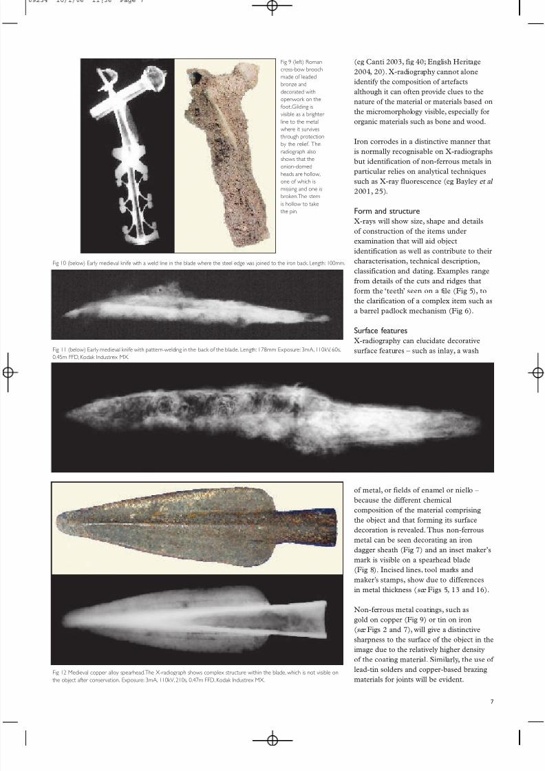
X-radiography may reveal tool marks that
can indicate if a non-ferrous metal vessel
was made by hammering (Fig 13) or
turned or spun on a lathe. It can also
provide details of manufacture of a cast
metal object and its quality, as revealed by
the extent of porosity visible (Fig 14).The
positions of ingates, for filling the mould,
may be seen. Chaplets that held the core
in place may survive or, if destroyed, may
be detectable as voids caused by
differential corrosion. Evidence for the
repair of items or the recycling of
materials, seen when features from an
earlier object is revealed, may also be
Fig 13 Hammer marks visible in the X-radiograph of a medieval copper alloy bowl show that the vessel was raised from sheet
metal. Dimension across: 108mm. Exposure: 3mA,110kV,120s, 0.47m FFD, Kodak Industrex MX.
Fig 14 Late Bronze Age spearhead. Porosity in the tip of
the blade, visible as dark areas due to voids in the metal,indicates that it was made by filling the mould with hot
metal from the blade tip. Exposure: 10mA,230kV,30s.
Fig 15 Late 16th-century ‘Jack of Plates’made from recycled iron sheet.The detail shows the plateswith distinctive rivet holes of the late 15th-century brigandine. Exposure: 5mA, 130kV, 30s.
:

7/29/2019 X Radiography
http://slidepdf.com/reader/full/x-radiography 9/16
9
and non-ferrous metal casting waste
(Fig 18), is sometimes found within
the soil or corrosion layers associated
with artefacts. Lead casting waste, if
oxidised, can be mistaken for mortar in
the soil unless it is X-rayed. Other
evidence can be found by X-raying soil
samples selected for specific
Fig 16 Early medieval shield boss as excavated (upper).The
X-radiograph reveals hammer marks aligned around the apex from
forging the iron boss to shape (middle).The studs are made from
silver alloy and thus show in the radiograph due to differences in
metal composition.These were revealed during conservation (lower).
Fig 17 (bottom) Soil samples containing ferrous hammerscale from a blacksmith’s hearth, comprising flakes and
spheres visible in the scanning electron micrograph. (top and middle) X-radiographs: top shows flake hammerscale,
comprising individual flakes that show as bright lines if they are vertical to the X-ray beam on exposure; middle
shows spherical scale, comprising hollow and part hollow spheres. Hammerscale can also be found within the
accretions surrounding an artefact.
visible in the X-radiograph (Fig 15).
Complex artefacts such as shield bosses
may reveal details of manufacture and
construction, including the use of
different metals (Fig 16).
Evidence of manufacturing processes,
such as ferrous hammerscale (Fig 17)
:

7/29/2019 X Radiography
http://slidepdf.com/reader/full/x-radiography 10/16
investigation, such as those from around
a smithing hearth (eg Bayley et al. 2001,
14; Starley 1995), or by X-raying certain
types of manufacturing implements,
such as ceramic crucibles for evidence of
non-ferrous waste metal.
ConditionThe archaeological interpretation of finds
can depend on features of condition,
such as completeness before burial, or
subsequent damage. Knowledge of the
condition of an artefact, in terms of the
presence of fissures (Fig 19), fractures
or the extent of mineralisation (Fig 20),
can inform decisions on subsequent
examination and the conservation
programme, particularly when finds are
very fragile.
6. How to make informativeX-radiographs
Film or digital?
At the time of writing (2005), the
standard image capture method in
archaeology is the production of
conventional film radiographs. In part
this is because of the much lower cost
associated with setting up such a
system. At present, the image quality of
medium-priced digital systems is not
sufficiently good for archaeological
applications other than for the basic
scanning of soil blocks. Digital systems
are improving in quality and may in
time become the standard technique for
image capture in relation to archaeological
archives (see Richards and Robinson
2000).The guidance offered in sections
1–5 will still apply.
Digitisation of film radiographs is
sometimes employed as a means of study
and dissemination between finds workers,
although the initial X-radiographs will
remain the prime source of data and
archive, and the quality of these originalX-radiographs is paramount. Image
enhancement is also employed, but its use
should be made known to the finds
researcher.These topics are covered in
more detail elsewhere (Lang and
Middleton 2005; O’Connor and Maher
2001; O’Connor et al 2002).
Film radiographs
Film radiography is essentially the same
as the process used for conventional
medical X-radiography in which a two-
dimensional negative image is captured
on photosensitive film (Fig 21).
The image size is approximately 1:1 if
the exposure is made with the artefact in
close contact with the film, although
dimensional distortions can arise for a
number of reasons (see below ).
To achieve the maximum information and
quality in X-radiographs requires someknowledge of the nature of the assemblage
and a rigorous methodology.The first will
enable the best orientations and exposures
to be selected, while the latter will facilitate
good quality images and a clear under-
standing of the relationship of the image to
the original artefacts. Operator skill and
experience plays a crucial part in the process.
For the basic principles and methodology
of X-radiography, the reader should refer
to standard texts, in particular Lang and
Middleton (2005). Detailed technical
information on equipment, materials and
methodology is available in publications
on industrial radiography (eg Kodak 1985;
1987; Quinn and Sigl 1980; Halmshaw
1986) and in manufacturer’s technical
data on specific products such as films,
processing equipment and chemicals (often
available through their web pages).
The sections below assume basic
knowledge of the X-radiography process
and offer guidance on how to achieve
clear and unambiguous images, suitable
for the purposes of identification, analysisand illustration, and to provide the
archival record.
Health and safety legislation
There are several statutory (legal) health
and safety requirements for any laboratory
using ionising radiations including X-rays,
and also for using certain related materials
and processes.
● The Ionising Radiations Regulations
1999
● The Control of Substances Hazardous
to Health Regulations 2002
10
Fig 21 Figure showing the basic layout during exposure.
Fig 18 Medieval nail.The X-radiograph shows non-ferrous
metal casting waste trapped within the corrosion layers.
Length: 65mm.
Fig 19 Bronze buckle from an early medieval grave.The
buckle is fissured and very fragile and now comprises
mostly tin oxide and copper carbonate.This is a
consequence of decuprification of the bronze in the acid
burial environment. Length: 21mm.
Fig 20 Roman nail, completely corroded.,The X-radiographreveals a void within the accreted block.
:

7/29/2019 X Radiography
http://slidepdf.com/reader/full/x-radiography 11/16
11
The equipment
The basic X-ray equipment, whether a
bench-top cabinet unit or a larger-scale
industrial unit, will have several variables
in terms of exposure:
● intensity, or quantity of the X-rays –
controlled by the current in
milliamperes (mA).This might not
be a variable for some cabinet units.
● energy, or quality of the X-rays –
controlled by the kilovoltage (kV)
● duration, or length of time of the
exposure
Film type
The preferred type of X-ray film to use
for archaeological artefacts is very fine
grain industrial film.This has film
emulsion on both sides and has highcontrast and high definition.
Film holders
X-ray film is light sensitive and is placed
in suitable light-tight holders (cassettes)
while being exposed to X-rays. Otherwise
it is only handled in the darkroom under
the illumination of an appropriate
safelight until fully processed. The film
is normally used within rigid cassettes,
in which lead intensifying screens are
held in close contact with the film.These
screens are employed with industrial type
film in order to minimize the effects of
Fig 22 Roman iron
stylus decorated
with brass and
silver (length:
108mm).The five
exposures of the
same stylus were
made by increasing
the X-ray energy
from left to right.
Left , the outline of the corroded
layers is visible as
well as the tip and
the eraser, but
very little detail of
the decoration can
be seen. Right , the
higher exposures
reveal detail of the
inlay, although this
is to the detriment
of the outline of
the whole
implement, which
appears to be
shorter as the tip
and eraser
become over
exposed and
merge into the
background.
Exposures, left to
right:70kV to
110kV in 10kV
steps,all at 3mA,
60s.
● The Control of Lead at Work
Regulations 2002
● http://www.hse.gov.uk/
The process of X-raying archaeological
material is usually completed within a
conservation laboratory, a museum or
university research facility. Staff
undertaking this work must comply with
the legislation.
What affects the image?
The image produced through
X-radiography depends on the interaction
of the X-rays with the materials under
examination, which is a function of the
artefacts, the equipment and the
exposure.The image quality is also
affected by film development conditions.
Details in the X-radiographic imagemight be missed if the viewing conditions
are inadequate.
The artefacts
Certain characteristics of the artefacts
will affect the image produced during
X-radiography.These are:
● thickness
● density
● chemical nature of the artefact (and
associated accretions)
● geometry and orientation in relationship
to the X-ray film
scattered radiation, thus improving image
contrast and increasing the exposure
latitude. At voltages above 120kV, the
screens will also serve to intensify the
image. At lower voltages there are
benefits in terms of reduction in scattered
longer wavelength radiation and improved
clarity and sharpness of the image.
Pre-packed film with integral lead screens
is also available, which in roll form is
particularly useful for long artefacts,
such as swords.
Occasionally it is useful to employ a
flexible cassette, for example to wrap
around a bulky object such as a vessel.
In these cases, the pre-packed film
mentioned above is useful, or the film can
be sealed within light-tight envelopes.
Whichever system is employed, everyeffort should be made to incorporate lead
screens within the cassette or envelope.
The exposure
Multiple exposures
It is often useful to make several
exposures of each artefact, either to adjust
the orientation of the object in the beam,
or to present a suite of images to suit
differentially degraded components or
areas of interest. For example, an iron
stylus decorated with non-ferrous metals
can be X-rayed to show different aspects
of its construction (Fig 22).
:

7/29/2019 X Radiography
http://slidepdf.com/reader/full/x-radiography 12/16
Another example, a medieval knife –
which will have a blade of wedge section,
possibly corroded away at the cutting edge
– will benefit from one exposure to match
the back of the blade and another to
match the cutting edge. If the handle is
complex, such as a decorated scale tang
handle, a third exposure at 90 degrees to
the other two exposures but in the plane
of the blade might be required, to reveal
the lengths of the rivets or other
constructional detail.There are a number
of potential constructional and
technological details that may be present
on knives, including makers’ marks,
microstructural detail such as welded-on
edges or pattern-welding (Fig 11),
complex decorated handles (Fig 23), and
traces of organic sheaths and handles
preserved as ferrous pseudomorphs where
the iron corrosion products have
concentrated (Fig 4).
Generally, multiple incremental exposures,
varying either exposure duration or
energy of the X-ray beam, will provide a
series of images of the same object toaccurately record the variation in its
morphology. Similarly, precise and
specific object rotations (usually through
90°) are equally important (Figs 3 and 5).
Suitable props can be made of radiolucent
materials (transparent to X-rays) such as
polyethylene foam cut into wedges or
other shapes.
Masking off
The easiest way to provide multiple
exposures is to mask off the film in its
cassette during exposure, allowing all
the exposures relating to a single item to
be placed on the same X-radiograph.
This is readily achieved with square-cut
sheets of roofing lead, placed to almost
butt up to the line of the previous sheet.
With care, numerous masking off
operations can be performed on one
film without the final developed
radiograph showing any white cut-off
lines, which occur if the lead sheeting
is overlapped (ie where film is not
exposed). However, image cut-off can
result from inexact masking, overlapping
the lead sheet on an area of previously
exposed object.The health risks
associated with handling lead dictate
that the appropriate protective equipment
be worn (The Control of Lead at Work
Regulations 2002), or the lead sheet can
be coated or covered.
Other factors to consider
1 To assist the division of finds to
different specialists, as well as to
produce a more useful archival record,
large assemblages can be X-rayed by
material or artefact type – for example
the coins can be separate from theother copper alloy artefacts.
2 Some groups of finds may comprise
numerous very small components
or dislodged fragments.These will
probably all need to be X-rayed,
and often at different exposure values
for the different components.This
can lead to complex imaging but
the additional time and patience can
be justified. Similarly, fragmentary
artefacts (with recent fractures)
may need to be repaired to enable
their forms to be properly understood.
3 X-radiographs that are overloaded
with artefacts can be confusing to
interpret.There should also be
sufficient space between items to
allow for labelling (see below ).
4 Optimum X-radiography is best
achieved when the surfaces of the
artefacts are in close proximity to
the film in order to minimize
distortions.This is one reason why
it is preferable to remove all or most
of the packaging surrounding the
artefacts, although very small or
fragile items can be exceptions
to this.
5 Distortions in the image can also occur
owing to the radiation beam angle.
6 The exposure required is also
affected by the film-to-focus distance
(FFD), which is the distance between
the film and the focal spot of the
X-ray tube.
7 Dimensional and other distortionsneed to be considered if artefacts are
illustrated from the X-radiographs.
Film development
The development of the film is an
important part of the process for high
quality, archival radiographs. A rigorous
darkroom routine is essential, from
development through to thorough
washing and drying. Manufacturers’
processing data sheets and darkroom
hints are useful sources of information
and can be downloaded from their web
pages.There are health and safety
12
Fig 23 Encrusted iron knife, 12th century.The X-radiograph reveals non-ferrous metal components on the bolster and tang, subsequently shown to comprise a bronze bolster at the junction of
the blade and tang, and numerous close-set brass plates on the tang. The latter were probably separated by thin horn plates, which no longer survive (Ottaway 2003, 272).
:

7/29/2019 X Radiography
http://slidepdf.com/reader/full/x-radiography 13/16
requirements for working with the
processing chemicals (The Control of
Substances Hazardous to Health
Regulations (COSHH) 2002).
Information on the safe disposal of
chemicals can be found in their Material
Safety Data Sheets and must comply
with local authority regulations on waste.
A high level of attention to detail is
critical when developing X-radiographic
film to produce useful images. If it is
lacking, the investment made in the
exposure process may be wasted.The
X-radiographic image should have a
uniformly black background and the lack
of a black background is diagnostic of a
badly processed film. The use of
exhausted processing chemicals produces
a streaky background in various shades
of brown. X-radiographs with this
appearance have no value in the archiveand should not be accepted. It can be
avoided by the rigorous monitoring of
processing chemicals.
Film labelling
The processed films require clear labelling
in a tidy and small format so as not to
interfere with the recorded image. White
ink is commonly used to mark the film
directly, although it is worth noting that
this method of marking will not be copied
during any digitisation process. Certain
minimum information, such as the
designated X-ray film number, the
accession numbers of the artefacts
examined, and diagrammatic
representations showing orientations of
the artefacts plus other relevant
information, must be recorded with the
X-radiograph.This information, together
with exposure parameters, will also be
recorded on the outer protective sleeve
of the X-radiographs (see below ), as
well as in a log book for the X-ray
equipment.The data forms part of the
‘X-ray archive’ and can be useful for
the interpretation of the X-radiograph.The designated radiograph numbers for
each item or groups X-rayed will form
part of the site archive and the research
archive, as separate ‘X-ray catalogues’
and through cross-reference to the object
catalogue (English Heritage 1991,A3.1.1,
A6.1.1).
It is also worth adding the X-ray film
numbers to the finds bags or labels as this
provides a quick method to retrieve the
correct radiograph when examining
objects, and may be a requirement of the
recipient museum.
Film protection
The emulsion layers of the film are very
vulnerable to scratching and to other
damage through handling, such as finger
marks. For protection, transparent covers
such as polyester sleeves are invaluable,
particularly when handling the finds and
the X-radiographs together duringassessments and many conservation
procedures, for example.
It is advisable to send objects and their
X-radiographs separately if they are
transferred between project members via
courier services. Nor should they be
boxed together: their storage requirements
differ and the potential damage to
X-radiographs from contact with dust
and other particles should be avoided.
Storage
The recommended environmentalconditions for processed X-radiographs
are 20 – 50% relative humidity at a
temperature less than 25ºC for medium-
term storage and less than 21ºC for
long-term (extended) storage (Brown
forthcoming; British Standards Institution
2000).
The enclosures for the films should be
inert, acid-free sleeves or envelopes.
Commonly, transparent polyester sleeves
are used, together with outer acid-free
paper or card envelopes, but the
requirements of the recipient museum
or repository should also be considered.
The outer paper or card envelope can be
printed or labelled in archival-quality ink.
Any plastic sleeves should be inert and
free of plasticiser. Chlorinated nitrated
or plasticised sheetings are highly
unsuitable and should not be used
(British Standards Institution 2000;
2001), nor should Glassine envelopes.
7. How to view the X-radiographs
Viewing radiographs in the correct
conditions is important to fully appreciate
the range of information available. Ideally,
they are viewed in a room where light
levels are reduced to a minimum, and
the radiograph is ‘back-lit’ on a light-box.
The unused areas of the front panel of
the light-box should be blanked off.
The temptation to view and attempt the
interpretation of carefully produced
images by squinting at them against an
inappropriate light source, such as a
window or desk lamp, should be avoided,
as it is impossible for the eye to cope
effectively with such wide variations
in light levels. A low-power lens such
as a photographer’s loupe (X4–X8
magnification) can be useful for closely
examining the detail in an image.
Project managers should ensure that
staff experienced in the interpretation of X-radiographs are engaged in the analysis
of the assemblage.The radiographs
should be consulted when objects are
illustrated to ensure that the form of the
actual items are depicted, rather than the
shape of the covering corrosion products.
X-radiographs might often be the best
way to publish artefacts, particularly
when they are very accreted or possess
intricate technological features. Complex
objects with internal workings such as
lock mechanisms (eg Egan 1998, 109,
fig 83) and other items, including theYork Coppergate helmet (Spriggs 1992,
901), knives (eg Cowgill et al 1987,
pls 2 and 5), and pattern-welded blades
(eg Lang and Ager 1989) all benefit
from the publication of X-radiographs.
Finds catalogues can also be enhanced
by judicious use of radiographs (eg
Haughton and Powlesland 1999).
8. How much should it cost?
It is often necessary to provide an
estimate of the cost for X-raying finds
from an excavation at the project
planning stage, before the quantity of
material is known. An estimate will
anticipate the volume of finds based on
past experience for the site type and
period within the region. Of course
if the volume of finds is known then a
more precise costing can be gained
from the organisation that will be
undertaking the work.
The cost for X-radiography will include
materials (the film and developing costs),time (labour), plus any overheads such
as laboratory and equipment expenses
not accounted for in the previous costs
(eg X-ray equipment maintenance costs
and compliance with health and safety
requirements).The time element will
depend on factors such as the condition
of the material (does it require repairing
before X-raying?), the packaging methods
(which can affect handling time),
annotating the radiographs and their
paper or digital records, the desirability
of multiple exposures, the size of objects,
and so on.
13
:
7/29/2019 X Radiography
http://slidepdf.com/reader/full/x-radiography 14/16
Costs can be affected by other, less
obvious, factors. When considering several
tenders one should be aware that the
lowest prices might not always provide
the best value for money. It is important
that not only high quality radiography but
also appropriate handling of the material
is specified and undertaken. Adequatepackaging to ensure the material is safely
transported is necessary and will affect
the overall cost.
Indicative costs (in 2005) for the
commonly employed 180 × 240mm size
X-ray film are as follows:
● materials and laboratory expenses –
£4 to £5 per film
● time (labour) – typically around eight
radiograph films can be completed in
a day where small items are X-rayed
(inclusive of exposure, developmentand marking-up). A greater number
of radiographs can usually be
completed in a day where large items
or large groups are X-rayed.
The numbers of objects per film will
obviously vary as indicated above, but
typically the following examples may
apply for each 180 × 240mm film as a
rough guide:
● 20 to 40 coins (less than 20 per film
if multiple exposures are made,
more than 40 coins per film in some
circumstances)
● 3 domestic knives (assuming
2 exposures of each knife)
● 1 complex barrel padlock (at
3 orientations)
● 30 nails (less than 30 per film if these
are large, or if they are bulky or
complex groups with mineralised wood
attached, such as those from coffins.
Conversely, perhaps 100 or more
individual hobnails would fit on an
X-ray film, depending on the method
of numbering, or a single hobnailedshoe sole).
9.Where to get help
Advice on facilities and laboratories
available for commercial and other work
can be obtained from the following
sources:
1 local archaeological conservation
laboratory services through local
authority and county museum
services, universities and other
institutions, and through discussion
with the other finds specialists involved
in the project ‘core team’
2 English Heritage, Fort Cumberland,
Portsmouth (tel: 02392 856704)
3 The Conservation Register of theInstitute of Conservation (formerly
United Kingdom Institute for
Conservation, UKIC).This is a
register of privately practising
conservators: Conservation Register,
c/o Institute of Conservation,
3rd Floor, Downstream Building,
1 London Bridge, London SE1 9BG
tel: 0207 785 3804
e-mail: [email protected]
www.conservationregister.com
4 English Heritage Regional Science
Advisors, listed below with theirregions:
North West
Sue Stallibrass
Department of Archaeology, Classics and
Oriental Studies, University of Liverpool,
William Hartley Building, Brownlow
Street, Liverpool L69 3GS
tel: 0151 794 5046
e-mail: [email protected]
North East
Jacqui Huntley
Department of Archaeology,
University of Durham, South Road,
Durham DH1 3LE
tel/fax: 0191 334 1137
e-mail: [email protected]
Yorksh ire
Ian Panter
English Heritage, 37 Tanner Row,York
YO1 6WP
tel: 01904 601983
e-mail: [email protected]
West MidlandsLisa Moffett
English Heritage, 112 Colmore Row,
Birmingham B3 3AG
tel: 0121 625 6875
e-mail: lisa.moffett@english-
heritage.org.uk
East Midlands
Jim Williams
English Heritage, 44 Derngate,
Northampton NN1 1UH
tel: 01604 735400
e-mail: jim.williams@english-
heritage.org.uk
East of England
Jen Heathcote
English Heritage, Brooklands House,
24 Brooklands Avenue, Cambridge,
CB2 2BU
tel: 01223 582759
e-mail: jen.heathcote@english-
heritage.org.uk
South West
Vanessa Straker
English Heritage, 29/30 Queen Square,
Bristol BS1 4ND
tel: 0117 975 0689
e-mail: vanessa.straker@english-
heritage.org.uk
London
Jane Sidell
Institute of Archaeology, University
College London, 31–34 Gordon Square,
London WC1H 0PYtel: 0207 679 4928
e-mail: [email protected]
South East
Dominique de Moulins
Institute of Archaeology, University
College London, 31–34 Gordon Square,
London WC1H 0PY
tel: 0207 679 1539
e-mail: [email protected]
Bibliography
Bayley, J, Dungworth, D and Paynter,
S 2001 Archaeometallurgy. English Heritage
Centre for Archaeology Guidelines,
2001/01. English Heritage Publications
Brickstock, R J 2004 The Production,
Analysis and Standardisation of
Romano-British Coin Reports . London:
English Heritage Publications
British Standards Institution 2000
Imaging Materials – Processed Safety
Photographic Films – Storage Practices ,BS ISO 18911: 2000 . London: British
Standards Institute
British Standards Institution 2001
Imaging Materials – Processed Photographic
Films, Plates and Papers – Filing Enclosures
and Storage Containers , BS ISO 18902:
2001. London: British Standards Institute
Brown, A forthcoming ‘The documentary
archive’, in UKIC Guidelines for the
Preparation of Excavation Archives for
Long-Term Storage (2 edn). London:
UKIC Archaeology Section
14
:

7/29/2019 X Radiography
http://slidepdf.com/reader/full/x-radiography 15/16
15
Canti, M G 2003 ‘X-ray studies of the
sediments’, in Brennand, M and Taylor,
M ‘The Survey and Excavation of a
Bronze Age Timber Circle at Holme-
next-the-Sea, Norfolk, 1998–9’,
Proceedings Prehistoric Society 69, 42–3
Cowgill, J, de Neergaard, M and Griffiths,N 1987 Knives and Scabbards . Medieval
Finds from Excavations in London,
1. London: HMSO
Department of the Environment 1990
Planning Policy Guidance: Archaeology and
Planning . PPG 16. London: HMSO
Department of the Environment 1994
Planning Policy Guidance: Planning and the
Historic Environment. PPG 15. London:
HMSO
Egan, G 1998 The Medieval Household Daily Living c 1150 –c 1450 . Medieval
Finds from Excavations in London,
6. London:The Stationery Office
English Heritage 1991 Management of
Archaeological Projects (2 edn). London:
English Heritage
English Heritage 2002 Environmental
Archaeology:A Guide to the Theory and
Practice of Methods, from Sampling and
Recovery to Post-excavation. English
Heritage: Centre for Archaeology
Guidelines 2002/01
English Heritage 2004 Geoarchaeology:
Using Earth Sciences to Understand the
Archaeological Record . English Heritage
Halmshaw, R 1986 Industrial Radiography .
Agfa-Gevaert
Haughton, C and Powlesland, D 1999
West Heslerton,The Anglian Cemetery,
Vol ii. Catalogue of the Anglian Graves and
Associated Assemblages. Yedingham:
The Landscape Research Centre
Institute of Field Archaeologists 2001
Standard and Guidance for the Collection,
Documentation, Conservation and Research
of Archaeological Materials . Reading: IFA
Kodak 1985 Fundamentals of Radiographic
Photography,Vol III, Radiographic Quality .
London: Kodak Ltd
Kodak 1987 Fundamentals of Radiographic
Photography,Vol II, X-ray Recording
Materials . London: Kodak Ltd
Lang, J and Ager, B 1989 ‘Swords of the
Anglo-Saxon and Viking Periods in the
British Museum: A Radiographic Study’,
in Hawkes, S C (ed), Weapons and Warfare
in Anglo-Saxon England , Oxford University
Committee for Archaeology Monograph
21, 85–122. Oxford: OUCA
Lang, J and Middleton, A (eds) 2005Radiography of Cultural Material (2nd edn,
revised). London: Elsevier
O’Connor, S and Maher, J 2001 ‘The
digitisation of X-radiographs for
dissemination, archiving and improved
image interpretation’. The Conservator 25,
3–15
O’Connor, S, Maher, J and Janaway, R
2002 ‘Towards a replacement for
xeroradiography’. The Conservator 26,
100–114
Ottaway, P 2003 ‘Knives’, in Hardy, A,
Dodd, A, and Keevill, G D, Ælfric’s Abbey;
Excavations at Eynsham Abbey, Oxfordshire,
1989–92 , Oxford: Oxford Archaeology,
Thames Valley Landscapes 16, 271–273
Quinn, R A and Sigl, C C (eds) 1980
Radiography in Modern Industry (4 edn).
Rochester, New York: Eastman Kodak
Company
Richards, J and Robinson, D 2000 Digital
Archives from Excavations and Fieldwork:
Guide to Good Practice (2 edn). Oxford:
Oxbow, and available at http://ads.
ahds.ac.uk/project/goodguides/excavation
(accessed 20 July 2005)
Roman Finds Group and Finds ResearchGroup AD 700–1700, 1993 The
Guidelines for the Preparation of Site
Archives and Assessments for All Finds Other
than Fired Clay Vessels. Roman Finds
Group and Finds Research Group AD
700–1700
Spriggs, J A 1992 ‘Conservation –
approach and methods’, in Tweddle, D
The Anglian Helmet from 16–22 Coppergate.
The Archaeology of York.The Small
Finds, 17/8, 894–901. London: CBA
Starley, D 1995 Hammerscale . HistoricalMetallurgy Society Archaeology Datasheet
10 (www.hist-met.org)
Watson, J and Edwards, G 1990
‘Conservation of Material from Anglo-
Saxon Cemeteries’, in Southworth E (ed),
Anglo-Saxon Cemeteries:A Reappraisal .
Proceedings of a Conference held at
Liverpool Museum 1986, 97–106. Stroud:
Alan Sutton
Health and safety
The Ionising Radiations Regulations 1999
(Statutory Instrument 1999 No. 3232).
HSE.The Stationery Office Ltd
The Control of Substances Hazardous to
Health Regulations 2002 (Statutory
Instrument 2002 No. 689). HSE.The
Stationery Office Ltd
The Control of Lead at Work Regulations
2002 (Statutory Instrument 2002 No.
2676). HSE.The Stationery Office Ltd
:
7/29/2019 X Radiography
http://slidepdf.com/reader/full/x-radiography 16/16
Published January 2006
Copyright © English Heritage 2006
Edited and brought to press by David M Jones,
English Heritage Publishing
Designed by Mark Simmons
Produced by English Heritage Publications
Printed by [printer]
Product code 51163
Acknowledgements
These guidelines were written and
compiled by Vanessa Fell, Quita Mould
and Rob White*. They have benefited
considerably by comments and
suggestions made by numerous colleagues
including conservators, finds researchersand other specialists, and the English
Heritage Regional Science Advisors.We
are extremely grateful to the following
people who commented on these
guidelines:
Liz Barham, Justine Bayley, Hilary Cool,
Jane Cowgill, Nina Crummy, Geoff Egan,
Liz Goodman, Karla Graham, Jacqui
Huntley, Jennifer Jones, Jackie Keily,
Janet Lang, Jannicke Langfeldt, Jo Mills,
Lisa Moffat, Dominique de Moulins,
Sonia O’Connor, Ian Panter, Sebastian
Payne, Jane Sidell, Jim Spriggs, DavidStarley, Judy Stevenson, Jacqui Watson
and Jim Williams.
We thank Tony Wilmott for identifying a
coin and permission to use the image
from current excavations. Justine Bayley
and Pete Wilson kindly provided
interpretations on other artefacts. John
Newman and John Sills agreed to the use
of images prior to publication of material
from excavations in Suffolk and in North
East Lincolnshire, respectively. We are also
grateful for permission to use images of
artefacts from excavations funded by
Archaeological Services University of
English Heritage is the Government’s
statutory adviser on the historic
environment. English Heritage provides
expert advice to the Government about all
matters relating to the historic
environment and its conservation.
For further information (and copies of this leaflet, quoting the product code),
please contact:
English Heritage
Customer Services Department
PO Box 569
Swindon
SN2 2YP
Telephone: 0870 333 1181
Fax: 01793 414926
e-mail: [email protected]
Durham (Figure 9) and by Chester City
Council (Figures 7 and 22).
Illustrations were contributed by
Lincolnshire County Council, Heritage
Service, and by David Dungworth,
Vanessa Fell, Karla Graham, Jennifer
Jones, Lucy Skinner, David Starley andRoger Wilkes.
Figures 14 and 15 are copyright of the
Board of Trustees of the Armouries.
Figure 8 is copyright of CTRL UK
Limited 2005. Figures 1(upper), 2a, 3,
6, 12, 13, 17 (part), 18, 20 and cover
image are supplied by kind permission
of Lincolnshire County Council,
Heritage Service. Figures 1 (lower),
2d, 4, 11, 16, 17 (part) and 21 are
copyright of English Heritage.
Illustrations may not be reproduced by
any means without written permission.
These guidelines are endorsed by the
Archaeology Group of the Institute of
Conservation, the Finds Research
Group AD 700–1700, and the Roman
Finds Group.
* This document should cited as Fell,V,
Mould, Q and White, R 2006 Guidelines
on the X-radiography of Archeological
Metalwork . Swindon: English Heritage
Cover figure: Post-medieval padlock as
excavated and with the padlock mechanism
revealed through X-radiography.
: