Embed Size (px)
Citation preview

www.labelingsystems.com pressure sensitive labeling Page 1 of 39

www.labelingsystems.com pressure sensitive labeling Page 2 of 39
Copyright © 2003 Labeling Systems Inc.
All rights are reserved including those of translation. This book and parts there of may not be produced in any form, stored in any retrieval system, or transmitted in any form or means without prior permission from Labeling Systems Inc. (LSI). The information contained herein is based on the experience and materials collected from public information sources. LSI is not responsible for the accuracy of its contents or for any damages that may occur because of errors or omissions. LSI does not by publication of this document ensure to anyone the use of such data against liability of any kind, including infringement of any patent. Publication of this data book does not constitute a recommendation of any patent or proprietary right that might be involved.

Pressure Sensitive Labeling
www.labelingsystems.com Page 3 of 39
1 Pressure Sensitive Labels The Pressure sensitive or PS labels we see on the products and cartons we use every day, every day consist of Face Stock and Adhesive. Depending on the adhesive used, they adhere to surfaces with moderate to light pressure. But the label we see is only part of the story. PS labels are constructed as a sandwich of several layers:
• Top Coat • Face Stock • Adhesive • Release Coat • Liner
Pressure Sensitive Label Construction Let’s build up from the bottom.
1.1 Liner The liner is the backing paper that makes up the web of a roll of labels.
1.2 Release Coat The release coat is a coating applied to the top surface if the liner. The release coat is designed to resist the adhesive, allowing the face stock and adhesive to peel away from the liner.
AdhesiveFace Stock
Top CoatRelease Coat
Liner
Label (Adhesive, Face Stock & Top Coat)
Web (Liner & Release Coat)

Pressure Sensitive Labeling
www.labelingsystems.com Page 4 of 39
1.3 Adhesive The adhesive is the glue that sticks the face stock to the product. There are a wide variety of adhesive formulations available. Adhesive selection is generally based on the application:
• Permanent or Removable • Product Surface Material – Paper, Plastic, Metal, etc. • Label Application Temperature • Product Storage Temperature • Product Surface Texture - Smooth or Rough • Wet or Dry Environment
1.4 Face Stock Although the most common face stock material is paper, many other materials are used including plastic films, foils, fabrics and laminates.
1.5 Top Coat The top coat is a coating or lamination applied over the face stock, to provide physical protection from abrasion or to enhance some other property of the label. Top coats can be used to improve adhesion or legibility of secondary imprints, typically used for date or lot coding. Special UV sensitive varnishes or films can be used to assist with label on product detection, during the labeling process.
Pressure Sensitive Labeling
www.labelingsystems.com Page 5 of 39
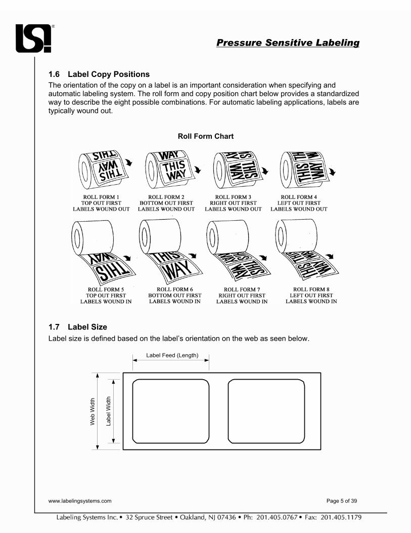
1.6 Label Copy Positions The orientation of the copy on a label is an important consideration when specifying and automatic labeling system. The roll form and copy position chart below provides a standardized way to describe the eight possible combinations. For automatic labeling applications, labels are typically wound out.
Roll Form Chart
1.7 Label Size Label size is defined based on the label’s orientation on the web as seen below.
Label Feed (Length)
Labe
l Wid
th
Web
Wid
th

Pressure Sensitive Labeling
www.labelingsystems.com Page 6 of 39
1.8 Web Length A roll of labels consists of a sandwich of web and labels, rolled in a spiral around a core. The chart below describes the length of the web on a roll of known diameter, based on the thickness of the label/web sandwich.
Web Length Chart
TOTAL THICKNESS OF COMPLETE CONSTRUCTION (MILS) O.D. (in) .0050 .0055 .0060 .0065 .0070 .0075 .0080 .0085 .0090 .0095 .0100
.002 Acetate
• Econ.Litho
• Lam. Foil
• MAC • tab
60# • Velvet
60#
• Gloss 60#
• Sat.004 • Vinyl • Metallics
• Radian Sat #8
• Rayon • Satin • Vinyl
Conv. Bdge. Gloss Cover 100# Tag
6 332 302 277 256 237 221 208 195 184 175 166
7 503 457 419 387 359 335 314 295 279 264 251
8 699 635 582 538 499 466 437 411 388 368 349
9 922 838 768 709 658 614 576 542 512 485 461
10 1170 1064 975 900 836 780 731 688 650 616 585
11 1445 1314 1204 1112 1032 963 903 850 803 760 722
12 1746 1587 1455 1343 1247 1164 1091 1027 970 919 873
13 2073 1885 1728 1595 1481 1382 1296 1219 1152 1091 1036
14 2427 2206 2022 1867 1733 1618 1517 1427 1348 1277 1213
15 2806 2551 2339 2159 2004 1871 1754 1651 1559 1477 1403
16 3212 2920 2677 2471 2294 2141 2007 1889 1784 1690 1606
17 3644 3313 3037 2803 2603 2429 2277 2143 2024 1918 1822
18 4102 3729 3419 3156 2930 2735 2564 2413 2279 2159 2051
19 4587 4170 3822 3528 3276 3058 2867 2698 2548 2414 2293
20 5097 4634 4248 3921 3641 3398 3186 2998 2832 2683 2548

Pressure Sensitive Labeling
www.labelingsystems.com Page 7 of 39
2 Label Converting The manufacture of pressure sensitive labels or label converting is a multi-step process. In some cases, all of the steps described below can be completed on a single production line. Other label converters may choose to split the process into two parts; printing and finishing. Label converting consists of:
• Unwind • Web Guide • Printing • Laminating • Die Cutting • Matrix Removal • Web Splicing • Slitting • Inspection • Rewind
Pressure Sensitive Label Converting Process
2.1 Unwind Label stock is unwound from a master roll and fed into the press.
2.2 Web Guides Web guides steer the web through the press to control print registration side to side. The web guides also control dimensional tolerances for the label and the liner.
Unwind
Color 1
Color 2
Color 3
Laminate Unwind
Die Cutting
Matrix Rewind
Slitting
Inspection
Rewind

Pressure Sensitive Labeling
www.labelingsystems.com Page 8 of 39
2.3 Printing One of the most common methods for printing pressure sensitive labels is flexography. On a flexo press, a flexible plate, imprinted with a negative of the image to be printed, is wrapped around a cylinder. Ink is transferred to the face of the plate. The web is rolled over the plate, transferring the image to the face stock. A flexo press includes one station for each color used in the label.
2.4 Laminating On labels that include a laminated top coat, the surface layer is adhered to the face stock after printing.
2.5 Die Cutting A label cutting die is very similar to a flexo printing plate, but rather than a raised image, the die surface is imbedded with “cookie cutter” like knives, designed to cut the face stock into the shape of a label. Under precisely controlled pressure, the web is rolled over the die. Set up of the die station is critical. The die must cut all the way through the face stock without cutting into the liner. Problems with too deep or too shallow cuts will be described later.
2.6 Matrix Removal During matrix removal, the matrix, the face stock material between the labels, is peeled from the liner and collected on a waste rewind roller.
2.7 Slitting To improve production efficiency and throughput, labels are typically printed four up or six up, that is four to six labels are printed across the face of the web. At the slitting station, the web is slit into four or six separate rolls of labels. Precise, web guiding in the slitting station ensures that the edges of the web are straight and parallel and that the label location on the web is consistent throughout the roll.
2.8 Inspection Using a strobe light, the images on the web are inspected using a vision system or a human inspector. Flags, little labels similar to “Post-it” notes, are attached to the web a the location of any defect. The flags are attached at the edge of the web, so the stick out of the roll. In a separate process, the roll is unwound and the defects are cut out. The roll is then spliced and rewound.
2.9 Rewind The most important factor at the rewind station is tension. If the roll is wound too tight, the adhesive may bleed. If the roll is too loose, it will be hard to handle and may telescope, when carried horizontally.
Pressure Sensitive Labeling
www.labelingsystems.com Page 9 of 39
3 Introduction to Pressure Sensitive Labelers Pressure Sensitive labelers came into existence during the 1950’s. Since their initial introduction, the use of labelers has grown into two basic application types
3.1 Apply Only – Use of Pre-printed labels in an automatic machine. There can be several purposes of this labeling including:
• Primary Decoration of the package • Promotional Labeling – many times may include the use of coupon type label stock • Security Seal – also known as tamper evident • Theft Security – uses labels such as Sensormatic ™ or Checkpoint ™ • Product Display – such as hang tabs
3.2 Print & Apply – the printing of labels is done by the labeler. This can either be done in a “next label out” configuration or with labels in que prior to being applied (ex. loose loop). This type is usually associated with bar coding. There can be several purposes for this type:
• Package Identification/Tracking – usually associated with shipping or
warehouse/distribution • Variable Printed Information – such as ingredients of a product or nutritional information. • Label Inventory Reduction – enables customer to reduce their inventory of pre-printed
labels. • Primary Decoration - is becoming a more viable application with faster machines and
greater print resolutions becoming available or for labeling provided by 2nd tier suppliers. Print and Apply is the fastest growing sector of pressure sensitive labeling. Thermal and Thermal transfer printing is accomplished using printers supplied by third party manufacturers. Many web sites offer detailed information and background on this technology. SATO and Zebra for example offers these documents located at : http://www.satoamerica.com/bcpsg_e.pdf http://www.zebra.com/SS/whitepapers.htm

Pressure Sensitive Labeling
www.labelingsystems.com Page 10 of 39
4 Labeler Categories Either of the application types can be matched to the following labeler categories:
4.1 Stand Alone Labeler- uses a labeler with a product handling system that is either existing or being provided by others. It may include a portable head mount (ex. T-base stand) or be installed directly on to a conveyor or other machine. This type of machine is also referred to as a “label applicator”.
Advantages
Usually the most price effective solution Typically takes up less floor space Easiest to install Very Flexible
Disadvantages
Does not maintain product control Will only guarantee label delivery accuracy not application accuracy Changeover may take longer
A Stand Alone Labeler
Pressure Sensitive Labeling
www.labelingsystems.com Page 11 of 39
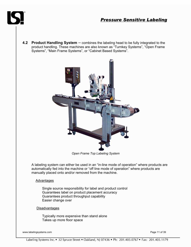
4.2 Product Handling System – combines the labeling head to be fully integrated to the product handling. These machines are also known as “Turnkey Systems”, “Open Frame Systems”, “Main Frame Systems”, or “Cabinet Based Systems”.
Open Frame Top Labeling System
A labeling system can either be used in an “in-line mode of operation” where products are automatically fed into the machine or “off line mode of operation” where products are manually placed onto and/or removed from the machine.
Advantages
Single source responsibility for label and product control Guarantees label on product placement accuracy Guarantees product throughput capability Easier change over
Disadvantages Typically more expensive than stand alone Takes up more floor space
Pressure Sensitive Labeling
www.labelingsystems.com Page 12 of 39
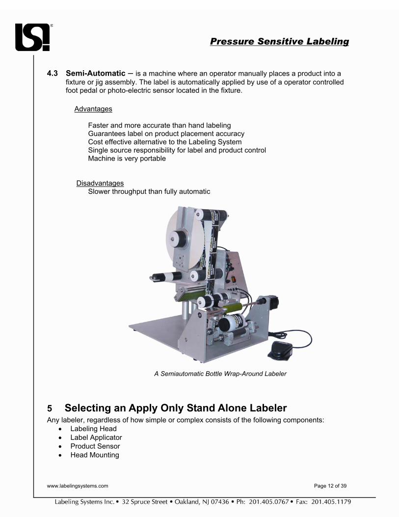
4.3 Semi-Automatic – is a machine where an operator manually places a product into a fixture or jig assembly. The label is automatically applied by use of a operator controlled foot pedal or photo-electric sensor located in the fixture.
Advantages
Faster and more accurate than hand labeling Guarantees label on product placement accuracy Cost effective alternative to the Labeling System Single source responsibility for label and product control Machine is very portable
Disadvantages Slower throughput than fully automatic
A Semiautomatic Bottle Wrap-Around Labeler
5 Selecting an Apply Only Stand Alone Labeler Any labeler, regardless of how simple or complex consists of the following components:
• Labeling Head • Label Applicator • Product Sensor • Head Mounting

Pressure Sensitive Labeling
www.labelingsystems.com Page 13 of 39
5.1 Labeling Head The base component required for automatic label applications. The labeling head serves as the platform for the unwinding and rewinding of the label material. The label applicator is installed on the head. In most cases the labeling head also houses the controls of the machine. Labeling head(s) are used in semi-automatic and fully automatic labeling systems. Other names for label applicators are: Automatic Labeler Labeling Applicator Labeler Head This term may sometimes be used to refer to the application device on a labeler, i.e. tamp label applicator.
5.1.1 Head Orientation Labeling heads can be supplied in either left or right hand version. Right hand machines feed label stock from left to right (viewing the machine from the front). A left hand machine feeds from right to the left.
5.2 Components of a Labeling Head A labeling head is comprised of several major subassemblies.
• Unwind Assembly • Web Drive • Peeler Bar • Label Sensor • Rewind Assembly • Controls

Pressure Sensitive Labeling
www.labelingsystems.com Page 14 of 39
5.3 Unwind Assembly This is the section of the labeling head where the label supply roll is mounted. This may sometimes be referred to as: Label Supply Roll Unwind Mandrel Unwind Supply In most labeling applications, labels are pulled from the unwind reel by the web drive assembly. A dancer arm is used to control a brake on the unwind reel. The brake stops the reel from spinning when the web drive stops pulling.
5.3.1 Roll Size This term is used to specify the outside diameter of the label roll and the inside diameter of the roll core. A typical labeling head allows a maximum roll size of 12” (304.8mm) O.D., wound on a 3” (76.2mm) I.D. core. Larger size rolls are also available.
5.3.2 Powered Unwind For high speed applications and for systems with large diameter label rolls, a separately powered unwind assembly may be utilized. The powered unwind assembly reduces the load on the web and drive system, improves label stop accuracy and minimizing web breakage.
12” Unwind
Dancer Arm

Pressure Sensitive Labeling
www.labelingsystems.com Page 15 of 39
Powered Unwind Drive and Nip Rollers (shown in horizontal configuration on a print & apply head)
Powered Unwind Drive and Nip Rollers
(shown in vertical dual unwind configuration)
5.4 Web Drive This refers to the roller assembly that pulls or pushes the web through the labeling head. The drive roller is always paired with a “nip” roller to insure the web stays fully engaged. Other names are: Label Nip Drive Nip Drive Rollers Nip Drive

Pressure Sensitive Labeling
www.labelingsystems.com Page 16 of 39
5.4.1 Web Drive Packages There are 3 basic web drive packages for apply only machines. These drive packages connect to the external drive roller that pulls the web through the machine
5.4.1.1 Clutch/Brake Drive This incorporates an AC or DC motor running continuously. A heavy duty clutch is used to engage the drive roller and a heavy duty brake is used to stop the drive roller. Typical linear rate for this is 0”/min to 1000”/min. The clutch and brake are wear components.
5.4.1.2 Stepper Motor Drive A stepper motor is used on a labeling head which drives the label web through the machine. Stepper motors do not have wearable drive components which lets them maintain label stop accuracy throughout the life of the machine. Some types of high position/accuracy stepper drives can have an encoder included to allow for the motor to adjust for speed changes to the product or product handling system. This is an open loop system and is sometimes called following mode.
Nip Roller
Drive Roller
Pressure Sensitive Labeling
www.labelingsystems.com Page 17 of 39
5.4.1.3 Servo Motor Drive Similar to a stepper motor drive, a servo motor drive uses an encoder on the transport system and an encoder on the motor. The pulses are matched to synchronize the motor to the transport system. Typically used for high speed and/or high accuracy applications, the advantage of this drive is that it is a "closed loop" drive. This means that speed variation feedback (via the encoder) is provided back to the Servo controller for it to automatically compensate for variances in speed to the product or product handling to which the encoder is attached. In a closed loop drive the feedback is more precise thereby creating greater labeling accuracy.
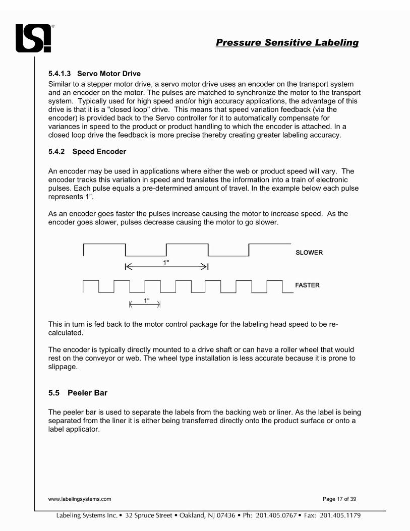
5.4.2 Speed Encoder An encoder may be used in applications where either the web or product speed will vary. The encoder tracks this variation in speed and translates the information into a train of electronic pulses. Each pulse equals a pre-determined amount of travel. In the example below each pulse represents 1”.
As an encoder goes faster the pulses increase causing the motor to increase speed. As the encoder goes slower, pulses decrease causing the motor to go slower.
This in turn is fed back to the motor control package for the labeling head speed to be re-calculated. The encoder is typically directly mounted to a drive shaft or can have a roller wheel that would rest on the conveyor or web. The wheel type installation is less accurate because it is prone to slippage.
5.5 Peeler Bar The peeler bar is used to separate the labels from the backing web or liner. As the label is being separated from the liner it is either being transferred directly onto the product surface or onto a label applicator.

Pressure Sensitive Labeling
www.labelingsystems.com Page 18 of 39
5.6 Air Assist Application methods using a vacuum pad or grid where the label is completely transferred from the web require air assist. The pad or grid is offset slightly from the peeler bar. This relationship causes the trailing edge of the label to break cleanly from the web backing. As the label is being peeled from the web it is deflected away from the applicator surface. Air is used to “push” the label back towards the applicator grid so the vacuum source can hold the label once it is fully dispensed.
5.7 Label Sensing For many labelers, the peeler bar also serves as the platform for the installation of the label sensor. The label sensor is installed as close to the peeling point as possible. This is called Peeling Tip Label Sensing. The advantage to locating the sensor at the peel point is that the label being sensed is being applied. This removes label converting variables thus providing the best label stop. It will also automatically advance to the next label should a label be missing from the web. On machines where the label sensor is located further back, a missing label(s) will cause a product to go unlabeled and a product to be double labeled. Machines equipped with a peeler extension typically do not have peeling tip sensing.
Peeling Tip Sensing

Pressure Sensitive Labeling
www.labelingsystems.com Page 19 of 39
5.7.1 Label Sensing (for machines equipped with Peeler Extensions) The label sensor is a "U" shaped sensor that consists of a photocell and a light source. It is adjustable by sliding it on a mounting bar. It is a coarse adjustment and should not be used for changing label stop or changeovers. Fine adjustment should be made with the label stop pot on the circuit board.
5.7.2 Photo-Electric Label Sensor (Label Photo-Cell/ Light Source)
The label photo-cell is used to detect the gap or printed bar located between labels by reading the contrast between the label and backing. The signal from the photo-cell is used to stop the label feed so that the label stops in the correct position. The photo-cell is mounted in the block located above the Peeler Bar. The light source emits a light which is received by the photo-cell. The assembly is mounted under the Peeler Bar. The label sensitivity potentiometer controls the amount of light that is emitted by the light source.
5.7.3 Clear Label Sensing (Capacitive Type)
This type of sensor is used for labels that visually have no distinguishable leading or training edge (such as a clear label) or if there is no registration mark on the liner or backing web. The sensor works by measuring the capacitance between the sensor and the peeler bar (or any grounded surface). When the label web is passed under the sensor, the capacitance between the sensor and the peeler bar is affected by the amount of material present. The sensor can distinguish the difference between a label and the gap between labels. A capacitive label sensor can typically detect the edge of a label within 1/64” of an inch. The sensitivity is controlled by a potentiometer directly on the body of the sensor. Some types of sensors may not be compatible with metallic inks printed on the label material.
Label Photo Cell
Clear Label Sensor

Pressure Sensitive Labeling
www.labelingsystems.com Page 20 of 39
5.8 Rewind Assembly In most labeling heads, the rewind drive is slaved by a timing belt or chain from the web drive motor. A slip clutch is used to maintain a constant tension on the web so as to insure the web does not break as it is being taken up. Many times a web release device is included on the rewind hub such as the “candy cane” type featured here.
5.8.1 Powered Type Rewind For systems designed for large diameter label rolls and wide webs a separately driven rewind assembly may be used. This eliminates rewind load on the web drive increasing label stop accuracy. This driven rewind included a quick web release feature to easily remove the spent backing roll of waste.
5.9 Apply Only Labeling Head Controls Every labeling head includes a control package that manages web advance and applicator functions. The control package can be mounted in the labeling head or in a remote enclosure. Most control packages allow the user to adjust several important labeler control parameters, including:
1. System Power – Controls power to motors, system controls and auxiliary devices.
2. Label Jog – Pressing the “Jog” button advances the web by one label, without triggering the applicator. This function is typically used during system set-up, product change over and after a roll change.
3. Label Sensitivity – Adjusts the gain of the label sensor. Proper gain adjustment allows
the label sensor to consistently sense the transition from label to liner, as the web moves forward. Label Sensitivity controls can be located on the labeling head control panel or on the label sensor itself.
4. Web Speed – On many labelers, the speed of the label web is adjustable. Labeling
speed is typically expressed in Inches per Minute (IPM).
Rewind “candy cane”
Quick Web Release

Pressure Sensitive Labeling
www.labelingsystems.com Page 21 of 39
5. Product Delay – This is the delay between sensing the leading (or trailing) edge of a
product and the beginning of the labeler’s apply cycle. Product Delay is typically measured in time. However, labeling systems that include an encoder on the product handling system can use counts from the encoder, to measure product delay. On time based systems, Product Delay must be adjusted either automatically or manually each time the product handling system speed is changed. On encoder based systems, product delay remains constant regardless of conveyor speed.
6. Label Stop - Label Stop adjusts the delay between sensing the edge of a label and
stopping the web. Label stop can be measured in time or in stepper or encoder counts. If Label Stop is measured in time, it must be adjusted either manually or automatically, each time the web speed is changed. On stepper motor driven labelers or on servo driven labelers with integral encoders, Label Stop can be measured in stepper or encoder counts. In these applications, Label Stop remains constant regardless of web speed.
7. Applicator Time – Applicator Time adjusts the amount of time the applicator is actuated,
i.e. for a tamp applicator, the amount of time a tamp pad is extended or for a blow-on applicator, the amount of time the air jet is energized.
Depending on the labeler manufacturer and model, labeler control parameters can be adjusted through dip switches and potentiometers or through digital Human Machine Interfaces (HMIs), with digital displays and keypads.
6 Selecting a Print & Apply Stand Alone Labeler Components of a print & apply labeling head.
• Print Engine • Unwind Assembly
Dip Switches Potentiometers HMI
Pressure Sensitive Labeling
www.labelingsystems.com Page 22 of 39
• Rewind Assembly • Controls
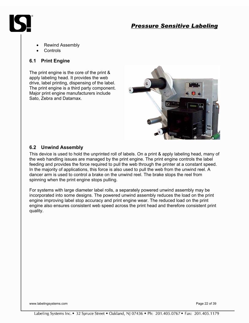
6.1 Print Engine The print engine is the core of the print & apply labeling head. It provides the web drive, label printing, dispensing of the label. The print engine is a third party component. Major print engine manufacturers include Sato, Zebra and Datamax.
6.2 Unwind Assembly This device is used to hold the unprinted roll of labels. On a print & apply labeling head, many of the web handling issues are managed by the print engine. The print engine controls the label feeding and provides the force required to pull the web through the printer at a constant speed. In the majority of applications, this force is also used to pull the web from the unwind reel. A dancer arm is used to control a brake on the unwind reel. The brake stops the reel from spinning when the print engine stops pulling. For systems with large diameter label rolls, a separately powered unwind assembly may be incorporated into some designs. The powered unwind assembly reduces the load on the print engine improving label stop accuracy and print engine wear. The reduced load on the print engine also ensures consistent web speed across the print head and therefore consistent print quality.

Pressure Sensitive Labeling
www.labelingsystems.com Page 23 of 39
6.3 Rewind Assembly All print & apply labeling heads utilize a separately driven rewind assembly to take up the spent backing web.
6.4 Labeling Head Controls In a print and apply head, the control features are divided between the print engine and the labeling head. The print engine manages the printing functions:
1. Print Speed – an adjustable setting determined by application rate, label material, print method (direct thermal v. thermal transfer), and desired print quality. Typically the slower the print speed setting, the longer the life of the thermal print head and the better the quality of the print.
2. Heat Control- the setting that controls temperature of the print head. The print head heat should be as low as possible to maintain the desired print quality and minimize the wear factor.
3. Label Out/ Low Ribbon/Ribbon Out – monitors these mediums required for label printing. These functions may be tied into a separate alarm package such as a beacon to provide a visual warning.
The print engine controls typically interface with label creation software. This is third party software used to create the visual image and layout of the label. The print & apply labeling head control package performs the following functions: Power to the Machine to control the labeling head motor(s) and power to an auxillary devices (such as a hot stamp). Label Jog- used to advance without activating the applicator. This is typically used during set-up or changeover.
A separately powered unwind is used for large diameter rolls.
Pressure Sensitive Labeling
www.labelingsystems.com Page 24 of 39
Label/Web Advance Functions
1. Air Assist – is required for applications that use a transfer method on to a pad or grid (ex. tamp pad or blow-on). The air assist stays on for the full time that the label is feeding. Further details in applicator section.
2. Applicator Time – used to control the amount of time the applicator solenoid stays on. This feature is required for most applications that use a transfer method onto a pad or grid (ex. tamp pad or blow-on). Example: this feature controls the length of time an air cylinder stays extended during the application sequence. Further details in applicator section.
3. Product Delay- used to control the start of the applicator sequence. By use of this delay
timer, the label position on the product can be changed in the direction of product travel.
7 Print & Apply v. Apply & Print On machines with thermal printers, there are two methods to set up the applicator. Apply & Print is when the product sensor is triggered, the applicator can apply the label and then feed the next label into the ready position on the tamp pad or vacuum grid. Print & Apply is when the product sensor is triggered, the labeler will print a label, feed it onto the vacuum grid or tamp pad, and apply the label. Sometimes one sensor is used to print the label and an additional sensor is used to trigger the machine to apply the label. This method allows for accurate placement of the label and a positive control of the application process.
8 Label Applicator Types The applicator is responsible for the delivery of the label to the product. The following are the general categories of an applicator:
• Wipe-on / Roll-on - can use a brush, roller, or other material to wipe the label down. • Vacuum Grid Wipe-on / Roll-on - label is peeled on to a spring loaded vacuum grid
and either rolled or wiped on to the product. • Blow-on – Uses a quick blast of air to apply the label to the product surface • Air Cylinder Tamp- Uses an air cylinder and vacuum pad combination to apply the label
on to the product surface. • Air Cylinder Wipe-on / Roll-on – is a hybrid of the Vacuum Grid Wipe-on / Roll-on and
the Air Cylinder Tamp. • Custom – a unique design to fit the specific product, product handling system, or other
custom requirement.

Pressure Sensitive Labeling
www.labelingsystems.com Page 25 of 39
8.1 Synchronous Type - can use a brush, roller, or other material. Also referred to as ”merge type”
Roll-on
This method is the oldest and most basic method of applying labels. It does exactly what it says, it rolls on the label as the label is being dispensed onto a moving product. It is capable of high speeds with good accuracy. The roller, usually made of foam or rubber, is usually spring loaded and mounted just ahead of the peeler bar. The limitations of the roll-on applicator are that the label must feed in the direction of product travel and must match the speed of the product.
Wipe-on/Brush-on This method utilizes the same principles of the roll-on applicator with the exception that a brush or wipe assembly replaces the roller. This type is usually selected with products that have high and low areas in the label placement area (ex. recessed panel) or products that are irregular in shape. Advantages • High application rate capability. • No change parts- can handle multiple
label sizes in both width and length (except vacuum grid variant).
• Can be mounted from top, bottom, or side.
Disadvantages
• Requires matching of speed of the label dispensing to the product travel speed.
• Applicator must be placed in direction of product travel (in line).
• Brush or Roller is a wearable component. • Applicator needs to be mounted close to
the product to make contact.
Pressure Sensitive Labeling
www.labelingsystems.com Page 26 of 39
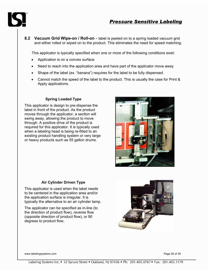
8.2 Vacuum Grid Wipe-on / Roll-on - label is peeled on to a spring loaded vacuum grid and either rolled or wiped on to the product. This eliminates the need for speed matching.
This applicator is typically specified when one or more of the following conditions exist:
• Application is on a convex surface
• Need to reach into the application area and have part of the applicator move away
• Shape of the label (ex. “banana”) requires for the label to be fully dispensed.
• Cannot match the speed of the label to the product. This is usually the case for Print & Apply applications.
Spring Loaded Type This applicator is design to pre-dispense the label in front of the product. As the product moves through the applicator, a section will swing away, allowing the product to move through. A positive drive of the product is required for this applicator. It is typically used when a labeling head is being re-fitted to an existing product handling system or very large or heavy products such as 55 gallon drums.
Air Cylinder Driven Type This applicator is used when the label needs to be centered in the application area and/or the application surface is irregular. It is typically the alternative to an air cylinder tamp. The applicator can be specified as in-line (to the direction of product flow), reverse flow (opposite direction of product flow), or 90 degrees to product flow.
Pressure Sensitive Labeling
www.labelingsystems.com Page 27 of 39
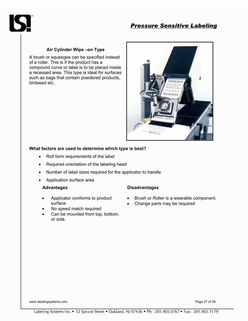
Air Cylinder Wipe –on Type
A brush or squeegee can be specified instead of a roller. This is if the product has a compound curve or label is to be placed inside a recessed area. This type is ideal for surfaces such as bags that contain powdered products, birdseed etc.
What factors are used to determine which type is best?
• Roll form requirements of the label
• Required orientation of the labeling head
• Number of label sizes required for the applicator to handle
• Application surface area
Advantages • Applicator conforms to product
surface • No speed match required • Can be mounted from top, bottom,
or side.
Disadvantages • Brush or Roller is a wearable component. • Change parts may be required

Pressure Sensitive Labeling
www.labelingsystems.com Page 28 of 39
8.3 Blow-on – Uses a quick blast of air to apply the label to the product surface. Also referred to as “air jet”.
This method blows the label down onto the product with a controlled blast of air. For good accuracy the distances between the product and the grid must be controlled closely (within 1”). This applicator cannot wrap without additional components such as a secondary wipe and has difficulty in accurately placing large labels.
Advantages:
• High Application rates – up to 1000/min depending on label size.
• No change parts – can adjust for different label sizes by changing pattern of air blast tubes.
• Does not make contact with product – important for products that are fragile in nature or applications where customer wants no contact of product (ex. certain food type products).
• Label is pre-dispensed - No speed match to product or conveyor necessary.
• Omni-directional – Applicator can be positioned either from top or sides. Applicator can be placed in direction of product travel (in line), reversed to product travel, or 90 degrees to product travel.
Disadvantages:
• Accuracies to +/- 1/16”. • Larger in size- may not fit into application
area. The Single label blow on or Air Cylinder Tamp/Blow may be viable alternatives.

Pressure Sensitive Labeling
www.labelingsystems.com Page 29 of 39
8.4 Air Cylinder Tamp
Uses an air cylinder and vacuum pad combination to apply the label onto the product surface. Also referred to as “air tamp” or “tamper”. The air cylinder tamp applicator is the slowest of all methods commonly used but it is the most accurate and easiest to set up. Basically the label is peeled away from the backing web and dispensed onto a “tamp pad”. The pad is designed to include a bevel to allow the label to transfer onto the pad. Air Assist is used to assist in the transfer of the label onto the pad. Once fully dispensed, the label is held in place by vacuum. Vacuum is created either through a transducer or by a high volume/low pressure system that incorporates a fan to create the vacuum. This system is typically used for larger label sizes.
Advantages:
• High accuracy to +/- 1/64”. • Easy to set up. • Interchangeable vacuum pads for different
label sizes. High volume/ low pressure system can run multiple label sizes without change pads.
• Can reach into tight or smaller target areas such as recessed panels on products.
• Label is pre-dispensed - No speed match to product or conveyor is necessary.
• Omni-directional – Applicator can be positioned either from top, sides or bottom. Applicator can be placed in direction of product travel (in line), reversed to product travel, or 90 degrees to product travel.
Disadvantages: • Makes physical contact with product. This
may be an issue for products that are fragile in nature. The tamp/blow alternative does address this concern along with other applicator types.
• Slower application rates. Depending on label size, application rates for tamps usually do not exceed 120/min. Typical rate usually falls in the 80-100/min or less range.
• Change part - sometimes the requirement for a change pad is viewed as a disadvantage. However the change part is what helps promote the ease of set up. Many times pads can be designed to handle multiple sizes without the requirement of a change part.

Pressure Sensitive Labeling
www.labelingsystems.com Page 30 of 39
8.5 Swing Arm Tamp This applicator is designed to apply a label to the either the leading or side panel of a moving or stationary carton. The labeling head can be oriented either to the side of the carton or above the carton. The orientation of the head is determined by:
• label roll form • location of label on the carton • location of the carton on the conveyor
The location of the head and applicator should be a close to the label target area as possible. This increases the response time of the applicator by minimizing the swing distance the applicator must travel.
8.6 Corner Wrap This applicator will apply a label to the front and side panel of a product. As the product passes the product sensor the label will feed out onto the vacuum grid. The label will need to be fully dispensed before the product makes contact with the applicator. The label will be applied to the front panel of the product. As the product continues through, the applicator will pivot around the corner of the product wiping down the side panel.
This type of applicator is normally designed to operate with a specific size label. The percentage of label on the front panel, in comparison to the side panel, is also taken into consideration during the applicator design.
The label is usually held in place by the use of vacuum. The vacuum can be created with either a vacuum transducer or by the use of a hi-volume fan. The specific parameters of the application and the label size will determine which method is used.

Pressure Sensitive Labeling
www.labelingsystems.com Page 31 of 39
8.7 Custom – a unique design to fit the specific product or other aspects of the application.
9 Criteria for selecting the correct applicator type
• Product Profile – concerns the surface area the label is to be applied. Example: is the surface flat, concave, convex or other profile.
• Label Size or Sizes – refers to width of label (dimension across the web), length of
label (the repeat or feed dimension) and the shape of the label.
• Label Material – usually paper or film. There are many other types of pressure sensitive material.
• Application Rate – usually measured in products per minute (ppm)*.
• Accuracy Requirements – what are the tolerances for label placement.
• Location of Label – is the label to be applied on the top, side, bottom etc.
* note – a common mistake is made when using the output rate of another machine (such as a filler) to determine the production rate of the labeler. Application rate is determined by the speed of the conveyor divided by the center distance between products (example – 2400”/min divided by 12” centers equals 200 products per minute.)

Pressure Sensitive Labeling
www.labelingsystems.com Page 32 of 39
Application Criteria Wipe-on / Roll-on
Vacuum Grid Wipe-on / Roll-
on
Blow-on Air
Cylinder Tamp
Air Cylinder Wipe-on / Roll-on
Custom
Product Profile
Convex X X X X X
Concave X X X Flat Panel X X X X X X Multi-Panel X X X X Recessed
Panel X X X X X
Raised Panel X X X X X Label Size See Applicator Section for Details Label Material
Paper X X X X X X
Film X X X X X X Application Rate See Applicator Section for Details
Accuracy +/- 1/32 +/- 1/32 +/- 1/16 +/- 1/64 +/- 1/32 As req. Location of Label
Top X X X X X X
Side X X X X X X Front/Back X X X X X X Leading/Trailing X X Bottom X X X X X Labeling Head Orientation
Left Hand X X X X X X
Right Hand X X X X X X Inline (direction
of flow) X X X X X X
90 degrees to flow X X X X X

Pressure Sensitive Labeling
www.labelingsystems.com Page 33 of 39
10 Product Sensor Also called “detector” or “photocell” and is used to detect the product to be labeled; or for verification, such as missing imprint or label.
TYPES OF PRODUCT DETECTORS
10.1 Infrared, Retro Reflective Product Detector: The reflective product detector is a single unit (modulated LED source and sensor) used with an optical reflector. The product detector is not affected by ambient light. Correct alignment of the product detector and reflector is most important. Proper alignment is indicated by a LED indicator on the scanner.
10.2 Infrared Proximity Product Detector (Diffuse Beam): The proximity detector is similar to the reflective type in that it requires the infrared beam emitted to return by way of a reflective surface. It is not dependent on an optical reflector, but rather the surface of the product reflects the beam to the sensor. This sensor is less accurate as it depends on product reflectivity.
10.3 Infrared Thru-Beam Product Detector: Comprised of the emitter and the sensor. Alignment of these components is critical. The fiber optic infrared thru beam-product detector version is a one-piece unit with two fiber optic light
guides.
Photoeye Reflector
Photoeye Object
Emitter Receiver

Pressure Sensitive Labeling
www.labelingsystems.com Page 34 of 39
10.4 Fiber Optic Product Detectors: Both the proximity and the thru-beam product detectors are available in the fiber optic version. This is useful in applications where product accessibility is limited
10.5 Convergent This sensor is used the least of all the sensors listed. This sensor is color sensitive and must be mounted at close range to the area being sensed, normally within one inch. It is very useful in detecting large differences in contrast such as registration marks on webs.
10.6 Mechanical Contact Product Detector: In this operation, a simple mechanical switch is set up so that the product opens the switch as it moves down the conveyor. This switch starts the machine cycle in the same manner as the optical detectors.
11 In-Line Imprinting Refers to the imprinting of labels with fixed or variable information during or just prior to label application on the label applicator. Common methods of in-line label imprinting include:
• Wet Ink • Hot Stamp • Thermal or Thermal Transfer • Ink Jet
Photoeye
Object
Photoeye Object

Pressure Sensitive Labeling
www.labelingsystems.com Page 35 of 39
A wet ink coder is rarely used on new equipment. Most in-line imprinting sold today is hot stamp or thermal/thermal transfer. Terms for print/apply, thermal and thermal transfer printing will be covered later. The following terms cover the basic of hot stamp imprinting:
11.1 Hot Stamp Imprinting Terms Hot Stamp Foil The web roll that carries dry ink. The dry ink is transferred by heat and direct contact with the label. Type Individual metal characters (alpha-numeric) used to form words or codes. Type is cast using zinc, brass or steel. Hardened steel type is preferred for long life. Type Holder Holds individual type characters to make codes or words in one or more line.
Impression Pad This is a rubber pad mounted to an anvil bar. The anvil bar and impression pad is mounted so that the label web passes between the impression pad and type holder. The impression pad takes the shock during hot stamp imprinting and is a normal wear part. Heater Temperature Control Imprint quality is governed by a number of factors including temperature. The temperature required depends on the imprint area, dwell time, foil type and label fact stock selected.
Impression Pad
Type Holder
Pressure Sensitive Labeling
www.labelingsystems.com Page 36 of 39
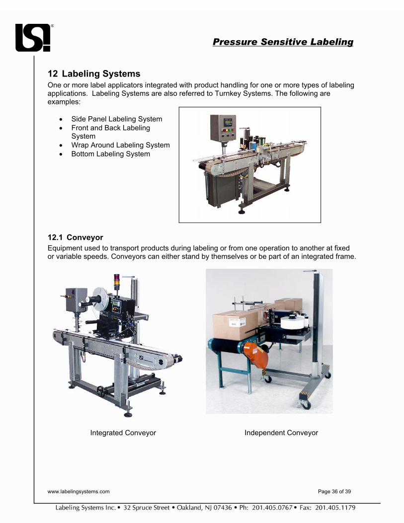
12 Labeling Systems One or more label applicators integrated with product handling for one or more types of labeling applications. Labeling Systems are also referred to Turnkey Systems. The following are examples:
• Side Panel Labeling System • Front and Back Labeling
System • Wrap Around Labeling System • Bottom Labeling System
12.1 Conveyor Equipment used to transport products during labeling or from one operation to another at fixed or variable speeds. Conveyors can either stand by themselves or be part of an integrated frame.
Integrated Conveyor
Independent Conveyor
Pressure Sensitive Labeling
www.labelingsystems.com Page 37 of 39
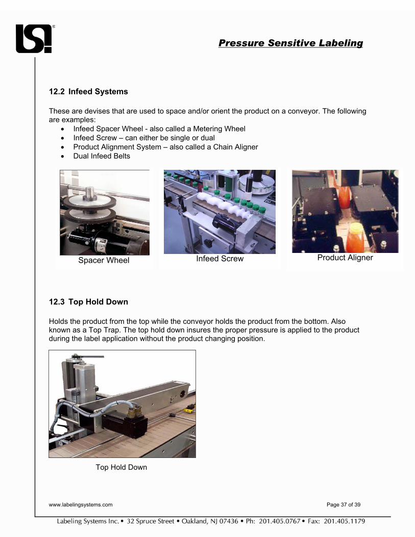
12.2 Infeed Systems These are devises that are used to space and/or orient the product on a conveyor. The following are examples:
• Infeed Spacer Wheel - also called a Metering Wheel • Infeed Screw – can either be single or dual • Product Alignment System – also called a Chain Aligner • Dual Infeed Belts
12.3 Top Hold Down Holds the product from the top while the conveyor holds the product from the bottom. Also known as a Top Trap. The top hold down insures the proper pressure is applied to the product during the label application without the product changing position.
Top Hold Down
Spacer Wheel Infeed Screw Product Aligner

Pressure Sensitive Labeling
www.labelingsystems.com Page 38 of 39
12.4 Wrap Station Used to wrap a label around a container. The devise is usually used for round containers but can also be utilized on squares, rectangular, triangular shaped products.
12.5 Secondary Impression Secondary impression refers to a secondary operation to ensure the label is applied completely, including the edges. Examples of secondary impression are:
• Secondary Roller Station (non-driven) • Driven Secondary Impression Roller Station • Secondary Tamp Station • Walking Beam
12.6 Verification The process of detecting for missing labels on the web, missing imprint, missing labels on the products or broken webs. This term is also used to describe the process of reading a code and then comparing it. This can be done with a simple photo cell, bar code reader, or a more complex vision system.
12.7 Semi-Automatic Labeler A labeling machine that requires an operator to load, feed or handle products during labeling. A labeling machine that is off-line from other packaging operations.
Secondary Roller
Pressure Sensitive Labeling
www.labelingsystems.com Page 39 of 39
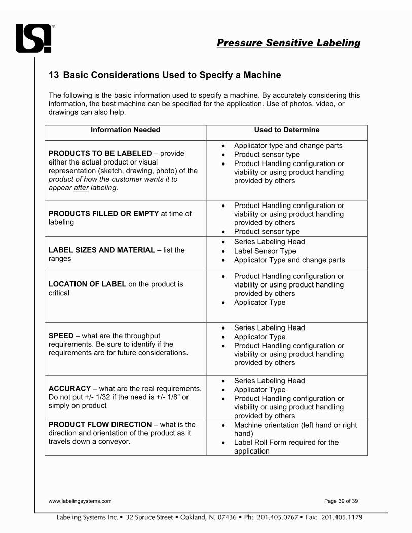
13 Basic Considerations Used to Specify a Machine The following is the basic information used to specify a machine. By accurately considering this information, the best machine can be specified for the application. Use of photos, video, or drawings can also help.
Information Needed Used to Determine
PRODUCTS TO BE LABELED – provide either the actual product or visual representation (sketch, drawing, photo) of the product of how the customer wants it to appear after labeling.
• Applicator type and change parts • Product sensor type • Product Handling configuration or
viability or using product handling provided by others
PRODUCTS FILLED OR EMPTY at time of labeling
• Product Handling configuration or viability or using product handling provided by others
• Product sensor type LABEL SIZES AND MATERIAL – list the ranges
• Series Labeling Head • Label Sensor Type • Applicator Type and change parts
LOCATION OF LABEL on the product is critical
• Product Handling configuration or viability or using product handling provided by others
• Applicator Type
SPEED – what are the throughput requirements. Be sure to identify if the requirements are for future considerations.
• Series Labeling Head • Applicator Type • Product Handling configuration or
viability or using product handling provided by others
ACCURACY – what are the real requirements. Do not put +/- 1/32 if the need is +/- 1/8” or simply on product
• Series Labeling Head • Applicator Type • Product Handling configuration or
viability or using product handling provided by others
PRODUCT FLOW DIRECTION – what is the direction and orientation of the product as it travels down a conveyor.
• Machine orientation (left hand or right hand)
• Label Roll Form required for the application