Embed Size (px)
Citation preview

Construction Methods and Minimization Measures
Biological Assessment Reference August 2019 WSF Capital, Repair, and Maintenance Projects 11
2 CONSTRUCTION METHODS AND MINIMIZATION MEASURES
This section describes types of marine demolition, installation, and reconstruction methods,
followed by a description of WSF structures, their functions, repair requirements, and MMs
common to these construction methods. The figures presented in this chapter do not represent
a specific terminal; rather, they are representations of typical WSF structures.
2.1 Construction Practices and Descriptions
2.1.1 Pile Removal, Repair, and Installation
Most ferry structures are pile-supported, including dolphins, wingwalls, towers,
bridge seats, and trestles. Therefore, repair or replacement of these structures typically
involves removal of timber and steel pilings, installation of steel or concrete pilings, or
repair of existing timber or steel piles.
Sections 2.1.1.1 through 2.1.1.8 describe the construction methods used for pile
removal and installation, pile materials, rock anchors, micropiles, drilled shafts, and
pile repair for pile-supported structures. Three methods of pile removal are described:
vibratory extraction, direct pull, and clamshell removal. Two methods of pile
installation are described: impact and vibratory hammer. The methods of timber or
steel pile repair include pile stubbing, steel collar, pile encapsulation, welding, or
installation of H-piles.
Pile Removal
Vibratory Extraction Vibratory extraction is a common method for removing both steel and timber piling.
A vibratory hammer is a large mechanical device mostly constructed of steel
(weighing 5 to 16 tons) with a hydraulic or electric power source, that is suspended
from a crane by a cable and positioned on the top of a pile. As the pile is vibrated,
the surrounding soil vibrates, reducing the resistance between the pile and the
sediments. The pile is then unseated from the sediments by engaging the hammer
and slowly lifting up on the hammer with the aid of the crane. Once unseated, the
hammer is disengaged, and the crane will continue to raise the hammer and pull the

Construction Methods and Minimization Measures
Biological Assessment Reference August 2019 WSF Capital, Repair, and Maintenance Projects 12
pile from the sediment. When the pile is released from the sediment, it is pulled
from the water and placed on a barge. Figure 2-1 shows a timber pile being removed
with a vibratory hammer.
Figure 2-1 Vibratory Hammer Removing a Timber Pile
Sediments attached to the outside of the pile fall back to the seafloor in a short
period of time (from several seconds to minutes to a few hours, depending on the
sediment type, currents, and weather conditions). The piling are loaded on to the
barge or into a container and disposed of off-site in accordance with Washington
Administrative Code (WAC) 173-304 and the MMs in Section 2.3.
Direct Pull and Clamshell Removal Timber pilings are particularly prone to breaking at the mudline due to damage
from marine borers and vessel impacts, but must be removed because they can
interfere with installation of new steel piling, causing construction delays and added
risk to construction workers. In some cases, removal with a vibratory hammer is not

Construction Methods and Minimization Measures
Biological Assessment Reference August 2019 WSF Capital, Repair, and Maintenance Projects 13
possible because the pile will break apart from the force of the clamp and the
vibration. Broken or damaged piles may be removed by wrapping the piles with a
cable or chain and pulling them directly from the sediment with a crane (Figure 2-2).
Figure 2-2 Direct Pull of Timber Piles
If the piles break between the waterline and the mudline, pile stubs are then
removed with a clamshell bucket. A clamshell bucket is a hinged steel apparatus
that operates like a set of steel jaws. The bucket is lowered from a crane and the jaws
grasp the pile stub as the crane pulls up (Figure 2-3). The broken piling and stubs
are loaded onto the barge for off-site disposal.
In some cases (depending on access, location, etc.), timber piles may be cut below the
mudline and the resulting hole backfilled with clean sediment.

Construction Methods and Minimization Measures
Biological Assessment Reference August 2019 WSF Capital, Repair, and Maintenance Projects 14
Figure 2-3 Removal of a Broken Pile with a Clamshell Bucket
Pile Installation
Impact Hammer Method Impact hammers are used to install plastic/steel core, wood, concrete, or steel piles.
An impact hammer is a steel device that works like a piston. Impact hammers are
usually large, though small impact hammers are used to install small diameter
plastic/steel core piles. Impact hammers have guides (called a lead) that hold the
hammer in alignment with the pile while a heavy piston moves up and down,
striking the top of the pile, and drives it into the substrate from the downward force
of the hammer on the top of the pile.
To drive the pile, the pile is first moved into position and set in the proper location
using a choker cable or vibratory hammer. Once the pile is set in place, pile
installation with an impact hammer can take less than 15 minutes under good

Construction Methods and Minimization Measures
Biological Assessment Reference August 2019 WSF Capital, Repair, and Maintenance Projects 15
conditions, to over an hour under poor conditions (such as glacial till and bedrock,
or exceptionally loose material in which the pile repeatedly moves out of position).
Figure 2-4 shows a pile being driven with an impact hammer.
Figure 2-4 Impact Hammer Driving a Steel Pile
When driving concrete piles, poor soil conditions (such as glacial till) can damage
the piles because they are not as strong as steel. There are two methods to help
advance a concrete pile in poor soil: jetting and the use of a stinger. Jetting refers to
water being forced with a compressor through a pre-cast passage in the pile (a “jet-
pipe”). The water flows out the end of the pile, helping to loosen soil so the pile can
advance with less damage. Jetting is typically done only when harder soils (such as

Construction Methods and Minimization Measures
Biological Assessment Reference August 2019 WSF Capital, Repair, and Maintenance Projects 16
glacial till) are encountered. A concrete pile is driven through softer soils without
jetting, then the jetting begins only when the glacial till layer is reached. In this case,
the tip of the pile may be 30 to 40 feet below ground surface before jetting begins, so
there is typically no turbidity on the surface of the soil or in the water column during
jetting. A stinger is an H-pile that is precast into the tip of the concrete pile. The
steel stinger breaks through glacial till, helping to advance the pile. Vibratory Hammer Method The vibratory hammer method is a common technique used in steel pile installation
where the type of sediment allows this method to be used. This process begins by
placing a choker around the pile and lifting it into vertical position with the crane.
The pile will then be lowered into position and set in place at the mudline. The pile
will be held steady while the vibratory hammer installs the pile to the required tip
elevation (Figure 2-5). For some load-bearing structures such as towers, wingwalls,
and trestles, the vibratory hammer can only install piles until they reach a certain
level of resistance. To meet certain design criteria and ensure proper functioning of
the structure, piles (steel, timber, and concrete) sometimes must be “proofed” by
striking them with an impact hammer. During the proofing process, an observer
records the distance the pile is embedded with each impact hammer blow. Data
collected during this process is then sent to the Project Engineer for review to ensure
the pile will meet the load-bearing design criteria.
Timber and concrete piles cannot be installed with a vibratory hammer and must be
impact driven.

Construction Methods and Minimization Measures
Biological Assessment Reference August 2019 WSF Capital, Repair, and Maintenance Projects 17
Figure 2-5 Vibratory Hammer Installing a Steel Pile
Pile Materials When new structures are installed, the pile material is steel or concrete. When
repairs to existing timber structures are needed, design criteria often require the
replacement of timber with timber rather than steel or concrete. Creosote and
ammoniacal copper zinc arsenate (ACZA) are the only approved marine wood
treatment options that meet design specifications. ACZA is the best available, EPA-
approved technology for protection of wood from marine borers in the marine
environment today, and is the treatment option currently used by WSF. Existing
timber dolphins are sometimes reinforced with 13-inch plastic/steel core piles. The
outer layer of plastic acts as a rub face so that when a ferry rubs against the dolphin,
the ferry and the dolphin are not damaged.
Construction Methods and Minimization Measures
Biological Assessment Reference August 2019 WSF Capital, Repair, and Maintenance Projects 18
Rock Anchors Several WSF facilities occur on bedrock with very little sediment overlay. These
facilities include Shaw Island, Orcas Island, Lopez Island, and Friday Harbor
terminals. For this reason, traditional pile driving methods may not be sufficient for
securing new steel structures in place. In these situations, rock anchors may be used
to ensure piles meet the engineering criteria, primarily uplift resistance, required for
structural loads and safe operations. The following steps are required for
installation of rock anchors:
• For freestanding structures like dolphins where the area cannot be accessed
via land, a small rock drill rig is mounted on an existing structure, or on a
temporary, pile-supported platform that is constructed around the pile.
• Each pile is installed with a vibratory hammer or impact hammer and driven
in the standard manner until the tip reaches bedrock. Design criteria
typically require the pile to be embedded at least 1 inch into sediment before
hitting bedrock.
• A smaller steel pipe casing is placed down the center of the steel pile with its
tip at the surface of the bedrock and is cast in place with concrete.
• The drill is placed in the smaller steel pipe casing, and augers a 6-inch-
diameter hole into bedrock.
• Steel dowels up to 1.75 inches in diameter (Figure 2-6), or a strand cluster of
up to 4 inches in diameter, will be inserted into the hole to the required
depth.
• The steel strands are tensioned to the required load and locked off. The
casing is then filled with grout (for both dowel and strand methods).
• If site conditions allow, sandbags are placed around the base of the pile to
prevent grout from leaking and coming into contact with surface water.

Construction Methods and Minimization Measures
Biological Assessment Reference August 2019 WSF Capital, Repair, and Maintenance Projects 19
Figure 2-6 Steel Strand Cluster Method of Rock Anchor Installation
A typical rock anchor is shown in Figure 2-7. Drill cuttings are captured at the drill
rig so they do not reach surface waters. Concrete and grouting is contained within
the pile and casing, and also will not reach surface waters.

1 3/4” o STEEL DOWELOR 4” STRAND PACK
3 - 6” DRILLED ANCHOR HOLE
OVERBURDEN
Figure 2-7Typical Rock Anchor Detail
WSF Biological Assessment Reference
01
/9/2
01
2 h
erik
sen
K:\
Job
s\1
00
01
6-W
SF\1
00
01
60
3\C
ore
lDR
AW
\REF
BA
\FIG
2-7
.cd
r

Construction Methods and Minimization Measures
Biological Assessment Reference August 2019 WSF Capital, Repair, and Maintenance Projects 21
Micropiles In some situations, micropiles can also be used at facilities located on bedrock as an
alternative to rock anchors. Micropiles are relatively small in diameter (8 to 12
inches) and are not as strong as piles installed with rock anchors; therefore, their use
is limited to situations with lower structural capacity requirements. Micropiles are
steel piling with a serrated edge (Figure 2-8) that are drilled 2 to 3 feet into the rock
rather than being installed with hammer. The pile is drilled from small equipment
located on the trestle. The resulting soil and rock fragments are flushed out to the
center of the pile with compressed air and contained for upland disposal. After the
pile is cleaned of drill cuttings, the center of the pile is filled with grout. The
micropile is then attached to the deck above with bolts and other fasteners.
Figure 2-8 Serrated Edge of a Micropile
Drilled Shafts Drilled shafts are needed to support hydraulic cylinders used in overhead loading
and transfer spans, and to support structures installed in deep water and/or thick
layers of soft sediments. To create a drilled shaft, a steel casing approximately 6 to
10 feet in diameter is driven into the substrate using a vibratory hammer (Figure

Construction Methods and Minimization Measures
Biological Assessment Reference August 2019 WSF Capital, Repair, and Maintenance Projects 22
2-9), and the material inside the casing is excavated using an auger or a clamshell
dredge (Figure 2-10). Augering is done within the casing such that no suspended
sediments are released to the surface waters. Auger tailings are removed from the
hole by mechanical means and disposed of upland.
The casing will be dewatered after augering. If required, a concrete seal at the base
of the casing will be poured to prevent water from entering the casing from below,
but depending on the till layer, the casing may not have any groundwater seeping
into the drilled shaft. Any additional water will be pumped out of the casing. All
water removed from the casing is run through a filter to comply with any issued
water quality certification before returning to Puget Sound, or is pumped into a
Baker tank for proper disposal. Sediments are disposed of upland.
During excavation, a bentonite or synthetic polymer slurry is sometimes added to
stabilize the walls of the shaft. When the shaft is of the desired depth, rebar
reinforcement is placed in the shaft (Figure 2-11) and concrete is poured with a
small-diameter flexible hose called a tremie. The concrete displaces any slurry that
was previously added and a vacuum hose is used to remove the slurry from the top
of the concrete (Figure 2-12).

Construction Methods and Minimization Measures
Biological Assessment Reference August 2019 WSF Capital, Repair, and Maintenance Projects 23
Figure 2-9 Vibratory Installation of Drilled Shaft Casing
Figure 2-10 Auger Excavation of Drilled Shaft

Construction Methods and Minimization Measures
Biological Assessment Reference August 2019 WSF Capital, Repair, and Maintenance Projects 24
Figure 2-11 Rebar Reinforcement of Drilled Shaft
Figure 2-12 Vacuuming of Slurry from Drilled Shaft

Construction Methods and Minimization Measures
Biological Assessment Reference August 2019 WSF Capital, Repair, and Maintenance Projects 25
Pile Repair Although WSF prefers to install new piling to make repairs, a process called pile
stubbing is sometimes used to repair timber piles. Pile stubbing is the only known
feasible option when piling under a trestle or dock require repair and when cutting a
hole and installing piling through the dock is not feasible (e.g., buildings on top of
the dock preclude installing piling through an existing dock). Pile Stubbing Pile stubbing is a process in which an existing, damaged length of pile above the
ground line is removed and replaced with a new length of ACZA-treated timber
pile. This process does not involve pile driving. Pile stubbing is often done at
elevations that are exposed at low tide. The process for pile stub repairs in the dry
involves cutting and removing a damaged timber pile between the ground line and
the underside of the pile cap (Figure 2-13). The remaining portion of the pile is
inspected for structural integrity. A 1-inch-diameter, 2-foot-long galvanized steel
pin is installed in the center of the pile, extending 1 foot from each side of the joint.
A new section of pile is then inserted between the cut section of pile that is still
embedded in the sediments and the underside of the structure the pile is supporting
(Figure 2-14). The pile surfaces are then cleaned of marine organisms. The form
must extend 30 inches below and above the joint of the two timber piles, often
requiring the excavation of small amounts of sediment around the base of the pile.
The sediment can be excavated with a backhoe, hand tools, shovels, or a siphon.
When the process is complete, the sand is returned to its original location and the
form, which extends above the high tide elevation, is removed.

Construction Methods and Minimization Measures
Biological Assessment Reference August 2019 WSF Capital, Repair, and Maintenance Projects 26
Figure 2-13 Pile Stubbing: Removing a Damaged Section of Pile
Figure 2-14 Pile Stubbing: Setting New Pile Section in Place

Construction Methods and Minimization Measures
Biological Assessment Reference August 2019 WSF Capital, Repair, and Maintenance Projects 27
Steel reinforcement is placed inside the form and concrete is then pumped into the
form to fill the void between the form and the pile. Concrete is poured through a
tremie. The mouth of the tremie hose is placed at the bottom of the form to prevent
splashing or accidental spillage of concrete. Sandbags placed around the base of the
form prevent seepage of concrete into the water.
An effort is made to complete certain tasks at the same time, in sequence. For
example, workers will attempt to replace pile segments on as many piles as possible
in a single low tide event, and at least one tidal cycle may occur before additional
steps (such as placing concrete) are completed.
WSF performs pile stub repairs in the dry whenever possible, as it is a more cost-
effective operation than performing the work in water with divers. However, when
a pile is located in deeper water such that the repair cannot be performed in the dry,
WSF will take additional steps to protect the marine environment. Commercial
divers use a hand-held siphon to excavate the area around the base of the pile for the
form to reach below the splice. The form is made long enough for the top to extend
above the high tide level and is not removed until the concrete is cured, in order to
prevent premature contact with marine water. Steel Collar Another method of timber pile repair is a steel collar used in place of a cast concrete
collar. The steel collar encases the pile and extends at least 1 foot beyond the joint in
both directions. The collar is bolted together around the pile (Figure 2-15). As with
the concrete collar, a galvanized steel pin is first installed inside the pile to reinforce
the pile at the joint. The primary difference between this and pile stubbing is this
method does not use concrete, rebar, or forms that require removal. However, use of
the steel collar method is limited because it is difficult to achieve a tight, sealed
connection between the old and new sections of pile if the old pile is warped or
deteriorated. If the section of pile stub remaining in the ground is in poor condition,
the cast concrete collar must be used.

Construction Methods and Minimization Measures
Biological Assessment Reference August 2019 WSF Capital, Repair, and Maintenance Projects 28
Figure 2-15 Pile Stubbing: Steel Collar Method
Pile Encapsulation There are different methods of pile encapsulation, but in general, encapsulation
refers to the process of encasing piling in concrete. Encapsulation is used when a
pile is damaged, but still retains some load bearing capacity. Damaged wood piles
can be repaired by encasing them in concrete using either a steel form or a fabric
form called a “seaform.” The seaform method is currently the only soft form that
will not leach concrete mix through the fabric.
Using the seaform method, piling to be encased are first cleaned of any loosely
adhering marine organisms. Reinforcing steel is then installed around the pile prior
to installation of the fabric form. All wires and rod ends are turned in toward the
pile to avoid damage to the fabric form. A custom fabricated jacket is then installed
around the entire pile. The top and bottom ends of the jacket are cinched with wire
cables to prevent concrete leaks. Concrete is then pumped into the fabric form
through a suitable hose extending down to the lowest point of the jacket. As the

Construction Methods and Minimization Measures
Biological Assessment Reference August 2019 WSF Capital, Repair, and Maintenance Projects 29
form is slowly filled with concrete, hydraulic pressure forces the entrained seawater
within the fabric form out through an overflow valve. The valve is fitted with a filter
that prevents suspended solids from discharging into surrounding waters. The
valve is permanently closed once the form has been filled with concrete. The typical
method for seaform installation is shown in Figure 2-16.

Figure 2-16Pile Stubbing Using a Sea Form
WSF Biological Assessment Reference
01
/9/2
01
2 h
erik
sen
K:\
Job
s\1
00
01
6-W
SF\1
00
01
60
3\C
ore
lDR
AW
\REF
BA
\FIG
2-1
6.c
dr

Construction Methods and Minimization Measures
Biological Assessment Reference August 2019 WSF Capital, Repair, and Maintenance Projects 31
Pile encapsulation with a steel form works much like the pile stubbing method
described above. A concrete plug is poured in the bottom of the form and allowed to
cure. Once cured, seawater is pumped from the pile and contained so as not to enter
surface waters. Concrete is then poured inside the form. The concrete pouring is
stopped once the concrete reaches a level below the top of the pile to prevent
concrete spillage. Encapsulation with a steel form is shown in Figures 2-17 through
2-19. In these figures, the encapsulation is being done in the dry. When done in
water, work is performed from a skiff by commercial divers.
Figure 2-17 Pile Prepared for Encapsulation

Construction Methods and Minimization Measures
Biological Assessment Reference August 2019 WSF Capital, Repair, and Maintenance Projects 32
Figure 2-18 Installing the Form
Figure 2-19 Completed Pile Encapsulation

Construction Methods and Minimization Measures
Biological Assessment Reference August 2019 WSF Capital, Repair, and Maintenance Projects 33
H-Pile Installation In some cases where a timber pile is failing, it may be very difficult to remove and
directly replace that pile (e.g. under a trestle with many piles close together). In this
case, repair will occur by driving an H-pile through the deck of the trestle, in the
approximate location of the failing timber pile. A cap will then be placed over the H-
pile and timber pile, effectively connecting the two and providing support for the
structure (Figure 2-20).
Figure 2-20 Completed H-Pile
Steel Pile Repair The use of steel piles in structures has been introduced over the last decade, and
breakage of steel piles is rare. However, when damaged, steel piling can be repaired
in several ways depending on the severity of the damage and the location of the pile.
If the pile is damaged above the water line, the pile may be cut off and a new pile
section welded on (Figures 2-21 and 2-22). If the damage is below the water line,
WSF will evaluate whether the pile can be removed with a vibratory hammer. If the
pile is pinched, bent, or otherwise damaged, removing the pile may not be feasible

Construction Methods and Minimization Measures
Biological Assessment Reference August 2019 WSF Capital, Repair, and Maintenance Projects 34
because the vibratory hammer may break the pile during removal. In this rare case,
the pile will be cut off at the mudline and abandoned. The approximate location of
the abandoned pile can be documented in as-built drawings.
Figure 2-21 Bent Steel Pile in Need of Repair
Construction Methods and Minimization Measures
Biological Assessment Reference August 2019 WSF Capital, Repair, and Maintenance Projects 35
Figure 2-22 Welding New Pile Section
Steel piles can also be repaired by encasing them in concrete. The process is very
similar to the process for timber pile encapsulation, described in Section 2.1.1.7.
Marine growth is removed and a form is fitted around the pile. When steel piles are
encased in concrete, the form is extended to the top of the pile. The form is then
filled with concrete. A plug is poured in the base of the form and allowed to cure.
Once cured, seawater inside the form is pumped from the pile and contained so as
not to enter surface waters. The concrete is then poured inside the form. Pouring is
stopped before the concrete reaches the top of the pile to prevent concrete spillage.
2.1.2 Dredging
Maintenance dredging at the ferry terminals is rarely required. Dredging may be
required for new slips or to prepare an existing slip to receive a larger class vessel or in
rare cases if a slip becomes silted in. Dredging is usually done with a clamshell dredge
deployed from a barge. Alternatively, the dredge may be deployed from land or the
trestle structure. Prior to dredging, sediments are tested to determine if they can be
reused, disposed of at a designated open water disposal site, or need to be disposed of
upland.
2.2 WSF Structures, Functions, Repairs, and Installation
The components of a typical ferry terminal, from offshore to onshore, include dolphins,
wingwalls, towers and headframe, transfer span with apron, bridge seat, trestle, pedestrian
overhead loading, and bulkhead and terminal building (Figures 2-23 and 2-24).

Construction Methods and Minimization Measures
Biological Assessment Reference August 2019 WSF Capital, Repair, and Maintenance Projects 36
Figure 2-23 Typical Ferry Terminal, Aerial View
Bridge Seat

Construction Methods and Minimization Measures
Biological Assessment Reference August 2019 WSF Capital, Repair, and Maintenance Projects 37
Figure 2-24 Typical Timber Ferry Terminal
Dolphins and wingwalls are structures that aid in the docking and mooring of ferries and
function to protect the structures behind them such as the towers, bridge seat, overhead
loading, and trestle. Dolphin and wingwall structures protect passengers and terminal
structures by absorbing high levels of energy, and these structures will collapse when
significantly overloaded under extreme conditions. Dolphin and wingwall structures
continually absorb the forces of ferry landings and departures and must withstand even
greater impact during inclement weather and at heavily used terminals. Dolphin and
wingwall structures are outfitted with different types of wearing and fendering materials
(i.e., rubber or polyethylene) that can be easily replaced, and extend the life of these
structures. Because dolphins and wingwalls are continually subject to extreme energy-
absorbing demands, they require regular preservation and repair work. Failure to maintain
these structures as scheduled or required may lead to catastrophic harm to the vessels,
passengers, crew, and property, and closure of facilities.

Construction Methods and Minimization Measures
Biological Assessment Reference August 2019 WSF Capital, Repair, and Maintenance Projects 38
These terminal structures have historically been built of creosote-treated timber, but WSF is
systematically replacing timber pile structures with steel or concrete pile structures when
they need to be repaired or replaced, and as funding for projects allows. New facilities will
be built with steel or concrete materials. Structural repairs vary from replacing one pile to
replacement of entire structures. Sometimes it is necessary to make repairs to timber
structures (particularly dolphins, towers, and wingwalls) by adding steel piles or new
ACZA treated timber piles to shore up the timber structures. Usually only a few steel piles
are needed to provide additional support. These structures are generally found at depths
greater than -15 feet mean lower low water (MLLW).
Most dolphins and wingwalls are fixed-pile structures, meaning they are driven into the
seabed; however, a few floating dolphins and floating wingwalls are in use. These floating
structures, attached to the seabed by steel chains attached to steel or concrete anchors, are
being replaced with fixed structures where possible as they are damaged and as funding
allows, because during high storm/wind events, some floating structures flip over, and they
do not withstand vessel impacts as well as fixed structures. However, in some locations
such as Lopez Island and Mukilteo, floating structures are required because geological
conditions such as bedrock do not allow for pile driving, and because the water is too deep
for traditional fixed-pile structures.
Sections 2.2.1 through 2.2.9 describe each component of the system; its function; and
common repair, maintenance, and preservation activities performed.
2.2.1 Dolphins
Function Dolphins are structures located offshore used to guide the ferry into the terminal and
hold it in place while docked or berthed (Figure 2-25). Ferry captains use the
dolphins to deflect misaligned vessels back into position during arrival and
departure. Newly constructed dolphins have a life expectancy of 50 years. Existing
timber dolphins have a life expectancy of 25 to 30 years.

Construction Methods and Minimization Measures
Biological Assessment Reference August 2019 WSF Capital, Repair, and Maintenance Projects 39
Figure 2-25 Vessel in Berth Using Dolphins to Maintain Position
Design
Dolphins are typically placed in several different locations for ferry approach, and
their positions vary by terminal location and orientation, type of vessels used, and
environmental conditions. The dolphin located farthest offshore is referred to as the
outer dolphin and is the largest of the dolphins. The next closest dolphin to shore is
called the intermediate dolphin and is slightly smaller, and the dolphin closest to
shore is called the inner dolphin and is the smallest of the three. Dolphins occur in a
variety of water depths. In general, inner dolphins occur in water depths from -25
to -35 feet MLLW, intermediate dolphins occur between -25 to -45 feet MLLW, and
outer dolphins occur between -30 to -55 feet MLLW. Not all terminals currently
have inner, intermediate, and outer dolphins in place, depending on terminal age,
class of vessel servicing the terminal, environmental conditions, and budget
allocation.

Construction Methods and Minimization Measures
Biological Assessment Reference August 2019 WSF Capital, Repair, and Maintenance Projects 40
Temporary Dolphins During repairs and construction within the ferry slip, the use of temporary dolphins
is sometimes necessary to allow vessel operations to continue during the repair and
to protect the damaged structure and the workers. The six- to eight-pile temporary
dolphins are typically placed in front of the construction area for the duration of the
construction activity and are removed when construction is complete (Figure 2-26). Fixed Timber Pile Dolphin There are standard timber dolphin sizes (35-pile, 70-pile, and 100-pile dolphins),
though dolphin sizes vary with site and conditions. Timber dolphins are typically
lashed in two places with multiple wraps of galvanized wire rope stapled to each
outside pile on each wrap (Figure 2-26). Timber dolphins are commonly faced with
high-density plastic (called ultra high molecular weight [UHMW] polyethylene) to
prevent wearing of the timber piling (Figure 2-27). Timber dolphins are no longer
the preferred method of design and will be replaced over time by steel pile dolphins
(described later) through preservation and improvement projects.

Construction Methods and Minimization Measures
Biological Assessment Reference August 2019 WSF Capital, Repair, and Maintenance Projects 41
Figure 2-26 Temporary Steel Dolphin and Fixed Timber Dolphin Structures
Fixed Timber Dolphin
Temporary Steel Dolphin Lashings

Construction Methods and Minimization Measures
Biological Assessment Reference August 2019 WSF Capital, Repair, and Maintenance Projects 42
Figure 2-27 Plastic Face Piling on a Fixed Timber Dolphin
Floating Dolphin Floating dolphins are structures that float on steel or polyethylene tanks or on
concrete pontoons (see Figures 2-28 and 2-30). Horizontal cap timbers are attached
to the floating tanks, creating a floating platform on which 12-inch by 14-inch
vertical timbers are erected to form a wall that absorbs the forces of incoming
vessels. If concrete pontoons are used, the timbers are erected on steel frames bolted
to the pontoons without any cap timbers.

Construction Methods and Minimization Measures
Biological Assessment Reference August 2019 WSF Capital, Repair, and Maintenance Projects 43
The vertical timbers are faced with 6- by 12-inch timbers that make up the wearing
surface, or rub face, of the dolphin. The rub face is usually covered with UHMW
polyethylene sheets to reduce the abrasion from repeated vessel contact. The wall is
braced with 12- by 12-inch timbers tied to the cap timbers or concrete on the non-
impact side of the platform. The rub face of the dolphin is not submerged.
Anchor chains are attached at the corners of the floating dolphin, and in some cases,
on the sides of the platform. They run out at an angle to the seabed and are
connected to concrete or steel anchors that position the dolphin to absorb the energy
of berthing vessels, and to prevent it from moving.
Anchors are installed by lowering them to the seafloor, from a workboat or tug, and
dragging them until the anchor fluke penetrates the seafloor and develops the
required holding capacity. The drag distance is a function of the soil type, factors of
safety, and the length of the anchor fluke, and it may take one or two runs to set each
anchor (see Figure 2-29).
Figure 2-28 Floating Dolphin and Fixed Steel Pile Dolphin
Construction Methods and Minimization Measures
Biological Assessment Reference August 2019 WSF Capital, Repair, and Maintenance Projects 44
Figure 2-29 Installation of Floating Dolphin Anchors

Figure 2-30Typical Floating Dolphin
WSF Biological Assessment Reference
01
/9/2
01
2 h
erik
sen
K:\
Job
s\1
00
01
6-W
SF\1
00
01
60
3\C
ore
lDR
AW
\REF
BA
\FIG
2-2
9.c
dr

Construction Methods and Minimization Measures
Biological Assessment Reference August 2019 WSF Capital, Repair, and Maintenance Projects 46
Steel Dolphin The size of steel dolphins varies with their distance from shore, depth, location,
intended energy demand, and class of vessel service provided. Figure 2-31 shows a
typical steel dolphin design. Outer dolphins are subject to the greatest demands,
and typically contain up to 15 to 25 steel piling, although double-sided dolphins
(serving two slips) contain about 30 piling (Figure 2-32). Intermediate dolphins
typically contain about 12 to 15 piling, and inner dolphins generally contain about
seven to 10 piling.
Though there are varieties of steel dolphin configurations in use, the materials and
general design have evolved into the structure shown in Figures 2-31 and 2-32.

Construction Methods and Minimization Measures
Biological Assessment Reference August 2019 WSF Capital, Repair, and Maintenance Projects 47
Figure 2-31 Typical Steel Dolphin

Jan
09, 2
012
11:5
0am
her
ikse
nK:
\Job
s\10
0016
-WSF
\100
0160
3\10
0016
03-B
A-00
1.dw
g FI
G 2-
31
Figure 2-32Typical Double-sided Steel Dolphin
WSF Biological Assessment Reference
SOURCE: Washington State Department of Transportation.
Construction Methods and Minimization Measures
Biological Assessment Reference August 2019 WSF Capital, Repair, and Maintenance Projects 49
The dolphin discussed here is a 13-pile design that would typically be used as an
intermediate dolphin. New steel dolphins are constructed of two groups of steel
pipe piling driven plumb (straight up). The back group (called reaction piling) is
constructed of seven to nine piling driven deep enough to provide stability. The
embedment is determined by sediment conditions, but is typically around 35 feet.
They are driven in a configuration spaced approximately 4 to 8 feet apart. This set of
piling is joined at the top with tube steel or a reinforced concrete diaphragm. The
front group includes four to five piling embedded approximately 20 feet. They are
spaced 9 feet from the nearest reaction piling and are connected to the diaphragm by
rubber marine fenders. The wearing face of the dolphin has a fender panel made of
steel and plastic attached to the front fender piling.
Repairs and Replacement of Dolphins
Timber dolphins are most frequently repaired by driving steel or ACZA-treated
timber piling behind or in front of the existing dolphin to reinforce the structure.
Another repair involves removing broken piling and driving recycled plastic piling
with a steel core (called face piling) in front of the dolphin and lashing them in place
with cable. A repair of this kind would typically take 3 days. If a timber dolphin
cannot be repaired, it is removed and replaced.
2.2.2 Wingwalls and Wingdolphins
Function Wingwalls protect the towers and transfer span from direct vessel impact and help
guide and hold the vessel in position (see Figures 2-23 and 2-24). Typical wingwalls
receive 12 to 40 vessel landings per day. Most wingwalls are fixed-pile structures
(Figure 2-33), but some float on anchored concrete pontoons. They are positioned at
an angle at the seaward end of the facility to catch the ferry and hold it in place.
Wingwalls typically occur in water depths between -25 and -40 feet MLLW. The
innermost section of the wingwall is called the throat (Figure 2-34). During vessel
landings, the ferry remains under power to maintain its position during loading and
unloading. During loading and unloading, most of the pressure from the vessel lies
directly on the throat of the wingwall. This section of the wingwall typically
requires regular preservation and repair work due to the heavy loads imposed on it.

Construction Methods and Minimization Measures
Biological Assessment Reference August 2019 WSF Capital, Repair, and Maintenance Projects 50
Figure 2-33 Typical Timber Wingwall—Back Side of the Structure
Figure 2-34 Wingwall Face

Construction Methods and Minimization Measures
Biological Assessment Reference August 2019 WSF Capital, Repair, and Maintenance Projects 51
Another wingwall structure is called a wingdolphin. Wingdolphins are dolphins
located where wingwalls usually are in relation to the transfer span and towers.
They perform the same function as wingwalls, but are not designed to withstand
normal vessel operations. They are configured as linear dolphins, not walls, and are
used at tie-up slip locations and at Lopez Island. Terminals currently with
wingdolphins include the Eagle Harbor Marine Maintenance Facility, Vashon, and
Port Townsend tie-up slips, and the Anacortes second tie-up slip.
Design
Timber Wingwall A typical timber wingwall contains 75 to 100 piling driven in four rows: the first
three rows are plumb, and the back row is driven at an angle (batter) (see Figure
2-33). The rows of piling are connected by 12- by 12-inch timber wales bolted
horizontally to the piling. Wales are also lashed to timber piling for additional
strength. The front of the wingwall is protected by 26-foot-long vertical rubbing
timbers that provide a wearing surface for the vessel. In many cases, steel H-piling
have been added to timber wingwalls over time to strengthen the structure as it
weakens under heavy use. The average usable life span of a timber wingwall is 15
years.
Steel Wingwall Steel wingwalls (Figure 2-35) contain fewer piling than timber wingwalls, usually 13
to 15 per structure. Steel wingwalls are designed similarly to timber wingwalls in
that they contain two rows of plumb piling and one row of batter piling or a third
row of plumb piling. A rubber fender between the first and second rows of plumb
piling absorbs much of the energy and returns the front row to its original vertical
position after an impact. The second row of plumb piling is driven deeper into the
sediment and braced with batter piling to minimize movement of the structure. Both
pile rows are welded together with horizontal I-beams to which rubbing timbers are
attached (Figure 2-35). They are designed for a 25-year life span.
Batter Pile

Construction Methods and Minimization Measures
Biological Assessment Reference August 2019 WSF Capital, Repair, and Maintenance Projects 52
Figure 2-35 Typical Steel Wingwalls (Side and Top Views)
Wingwall Removal, Repair, and Installation Wingwalls can be replaced by different methods, depending on the severity of
damage to piling being removed and the limits of operational closures. If the timber
piling comprising the wingwall are in good condition, the wingwall can be
dismantled and the piling can be removed with a vibratory extractor, but this
process is very time-consuming and results in extended closures of the facility.
Another method of removing piling is cutting the piles below the rub face and lifting
the entire rub face onto the barge in one piece. The piles can then be removed using
the vibratory, direct pull, or clamshell method depending on the condition of the
piles. In the event that a large number of piling associated with a wingwall are in
poor condition or are broken at the mudline, or if reducing facility closure time is
critical, wingwalls can be pulled over using a crane or a tug boat and removed.
Using this method, the entire wall will come out in one piece. A clamshell bucket
may then be used to remove broken pile stubs (see Figure 2-3).

Construction Methods and Minimization Measures
Biological Assessment Reference August 2019 WSF Capital, Repair, and Maintenance Projects 53
The decision to choose one removal method over another is contingent upon several
factors, including pile condition, tides, and the length of facility closure time. To
dismantle the wingwalls and pull piles individually takes approximately 7 days. To
remove them in one piece, it takes approximately 2 to 3 days per wingwall. Length
of time for each method must be taken into consideration if the slip is closed to
operations.
Each replacement steel wingwall is installed by driving steel piling to the required
depth, then cutting it off at the desired length. To ensure that the piling are installed
in the correct position, a temporary template is often used to guide the piling into
place (Figure 2-36).
Figure 2-36 Template Used During Steel Wingwall Installation
The template consists of four to six temporary steel piling that support a steel
template with holes through which the permanent piling are driven. In some
instances, several temporary H-piling may be driven in front of the construction area
to protect work crews and equipment from incoming vessels if repair work is being

Construction Methods and Minimization Measures
Biological Assessment Reference August 2019 WSF Capital, Repair, and Maintenance Projects 54
conducted while the slip is in operation. Once the piling are driven through the
template, a prefabricated wingwall frame is set on top of the piling and fastened
(Figure 2-37).
Figure 2-37 Crane Installing Steel Wingwall Frame
2.2.3 Towers and Headframe
Function Some towers and headframes operate like a drawbridge and contain a
counterweight-and-cable system that supports the offshore end of the transfer span,
allowing for its raising and lowering to meet the car deck of the ferry at all tide
elevations. Towers and headframes are constructed of timber and/or steel, both with
the same general configuration (see Figure 2-24). Towers are typically placed in
water depths ranging from -20 to -40 feet MLLW.
WSF is currently installing an alternate tower design as a new standard for all WSF
facilities. The design is a system called an H-span, which uses hydraulic cylinders to
move the transfer span up and down instead of the existing system of cables and
counterweights (Figure 2-38).

Construction Methods and Minimization Measures
Biological Assessment Reference August 2019 WSF Capital, Repair, and Maintenance Projects 55
Figure 2-38 Compression Cylinder Tower System
Design Cable-Counterweight System Both steel and timber towers stand approximately 40 to 45 feet above MLLW for
structural support and clearance. Steel towers consist of a group of plumb and
batter piling capped with concrete. A steel headframe sits on the concrete cap.
Timber headframes are continuous piling that extend to the top of the tower.
The steel or timber piling are tied together with framing to create a rigid structure to
support the headframe. The headframe is constructed of horizontal beams that span
the distance between the towers. The counterweight cables are attached to, and run
across, the headframe in a rigging system that supports the offshore end of the
transfer span and allows it to raise and lower to meet the vessel vehicle deck.
Hydraulic System The hydraulic system (H-span) uses compression to raise and lower the transfer
span. The cylinder hydraulic tower structure is primarily composed of two 5- to 6-

Construction Methods and Minimization Measures
Biological Assessment Reference August 2019 WSF Capital, Repair, and Maintenance Projects 56
foot-diameter steel casings mounted on a concrete plug installed with the drilled
shaft method (see Section 2.1.1.6). Figure 2-38 shows a compression cylinder tower
system.
Repairs and Replacements to the Towers and Headframe If a timber tower pile is damaged, it can be repaired by replacing sections of the
damaged pile, if possible (see Section 2.1.1.7). A more typical repair includes adding
steel piling to shore up or provide lateral support for the tower. Timbers, 12 inches
by 12 inches or larger, are usually bolted on the outside of each tower. Steel or
timber piling are then driven at an angle to the tower and attached to the 12-inch by
12-inch timber with a steel collar. Depending on the location and function of the
piling, repair may consist of concrete encasement. If a steel tower pile is damaged,
additional piling is installed to shore up the tower or the pile is removed and
replaced. If a steel pile cannot be repaired, it is removed and replaced with a new
pile. Total in-water work, including pile driving, takes approximately 2 days per
pile (about 3 hours of in-water work).
2.2.4 Transfer Span/Apron
Function The typical transfer span is a steel girder bridge structure approximately 90 feet long
and 24 feet wide that carries two lanes of traffic between the trestle and the ferry (see
Figures 2-23 and 2-24). The transfer span rests entirely above water. The transfer
span is seated at the onshore end on the bridge seat and suspended at the offshore
end from the tower headframe or H-span. The transfer span is raised or lowered by
machinery housed in the tower, or by hydraulic lifts. The transfer span ends beyond
the headframe in a 15-foot-long lipped apron that adjusts hydraulically or by cables
up or down to accommodate minor changes in elevation as vehicles cross from the
transfer span onto the ferry deck.
Design The transfer span is constructed of steel or timber stringers running the length of the
span tied into floor beams, and end beams running perpendicular to the stringers.
The lift beam is wider than the span itself and is attached to the headframe system.
Construction Methods and Minimization Measures
Biological Assessment Reference August 2019 WSF Capital, Repair, and Maintenance Projects 57
The span is decked with a variety of materials including timber laminates, concrete,
or steel, and is covered with a wearing surface, typically asphalt. Older timber
transfer spans used creosote-treated timber laminated decking beneath an asphalt
cap.
The apron is hinged to the offshore end of the span. The apron is raised or lowered
with a hydraulic cylinder and lever arm, or a similar cable system. There are
smaller, hinged steel flaps called apron lips that connect to the end of the apron. The
apron lips provide stability during loading and unloading as the vessel moves in the
water. The apron lips are attached to the apron by bolts that allow them to swing
freely within a limited range.
Removal, Replacement, and Installation of the Transfer Span and Apron The transfer span and apron occur above mean higher high water (MHHW), but
repair and replacement work typically occurs from a derrick on the water. The
transfer span and apron are unsupported structures spanning between the bridge
seat and the tower structures. The transfer span and apron are typically lifted off the
supporting structures with a derrick and removed from the site (see Figure 2-39).

Construction Methods and Minimization Measures
Biological Assessment Reference August 2019 WSF Capital, Repair, and Maintenance Projects 58
Figure 2-39 Removal of a Transfer Span
The refurbished or replacement transfer spans and aprons are brought to the
construction site on a barge. Each component is then lifted into place with the crane
and set into position. Work to weld, bolt, and fasten these structures is generally
conducted from the trestle.
2.2.5 Bridge Seat
Function The bridge seat is a pile and cap structure that supports the fixed end of the transfer
span and provides a pivot point for the transfer span to be raised and lowered.
Bridge seats generally occur in water depths of -10 to -35 feet MLLW.
The bridge seat is typically constructed of two clusters of four piling tied together
with a concrete cap and beam. Older facilities were built with multiple timber pile
caps and beams (Figure 2-40).

Mar
20,
201
2 5:
07pm
tgri
gaK:
\Job
s\10
0016
-WSF
\100
0160
3\10
0016
03-B
A-0
01.d
wg
FIG
2-3
9
Figure 2-40Typical Timber Bridge Seat
WSF Biological Assessment Reference
SOURCE: Washington State Department of Transportation.

Construction Methods and Minimization Measures
Biological Assessment Reference August 2019 WSF Capital, Repair, and Maintenance Projects 60
Repairs or Replacements Bridge seat piling can be repaired in several ways, depending on the severity of
damage to the structure. The structure can be supported by driving additional
piling beneath or next to the structure to stabilize it. Most bridge seats can be
supported with as few as two to four additional steel piles. However, in rare cases
where access is difficult or impossible, up to eight additional steel piles may be
required to support a bridge seat. A more complex repair involves detaching the
entire transfer span and removing it from the site, and removing the old piling and
driving new piling. A cast-in-place or pre-cast concrete cap is installed to connect
the steel piling. Cast in place structures require the use of forms to contain the
concrete until it cures. Forms are sealed with rubber or foam to ensure no uncured
concrete escapes (Figure 2-41).
Figure 2-41 Forms Used for a Cast-in-place Concrete Pile Cap
After the piling are driven, the bridge seat is reassembled and the transfer span is
put back in place. This requires that the ferry slip be closed and results in
operational interruptions. Alternatively, a new bridge seat can be built with the
transfer span in place during most of the construction to minimize closure time.
However, this requires short-term closures and potential operational interruptions.

Construction Methods and Minimization Measures
Biological Assessment Reference August 2019 WSF Capital, Repair, and Maintenance Projects 61
Installation Installation of a new bridge seat is accomplished in the same way a new trestle is
installed (see Section 2.2.6.3).
2.2.6 Trestle
Function A trestle is a fixed-pile structure that carries passenger and vehicle traffic from shore
to the transfer span (see Figures 2-23 and 2-24). The trestle may be relatively short in
an area with a steep beach, or long in gently sloping areas. Trestle widths vary by
ferry terminal.
Design The trestle is constructed of a series of rows of piling that, when connected by a
common cap, are called “bents” (see Figure 2-42). The bents provide support for the
vertical load. The term “bent” includes the pile cap and all the piles that support it.
Timber trestles are supported by the cross-bracing installed between the bents or by
batter piling (Figure 2-42). The distance between the bents (and therefore the total
number of piling required for the trestle) is determined by the load that the structure
is expected to support, and the pile and pile cap capacity. The bents are linked at the
top by stringers running from cap to cap for the length of the trestle. Older stringers
are generally creosote-treated wood, and newer trestles are built with reinforced
concrete stringers (Figure 2-42). The stringers are topped with one of a variety of
decking materials; the decking is typically covered with asphalt.

Construction Methods and Minimization Measures
Biological Assessment Reference August 2019 WSF Capital, Repair, and Maintenance Projects 62
Figure 2-42 Under a Timber and Concrete Trestle
Repairs or Replacements to the Trestle Piling replacement under an existing trestle is not a simple project. There are several
methods of replacing a pile under a trestle. One method involves lifting the decking,
removing the damaged pile and driving a new one in the same location, or driving a
new pile adjacent to the damaged pile and removing the damaged pile entirely if
Bent of Piles
Stringers

Construction Methods and Minimization Measures
Biological Assessment Reference August 2019 WSF Capital, Repair, and Maintenance Projects 63
possible, or cutting it off below the mudline and capping it with clean material. To
install a pile through the decking, an approximately 2-foot-square piece of decking is
removed and the pile is driven through the hole. However, because the pile
supports a timber (usually) pile cap, the new pile must be driven at a slight angle
and bent back to slip underneath to support the pile cap. The decking is then
replaced. Micropiles, described in Section 2.1.1.5, may be used to replace timber
piles.
Other methods used to repair trestle piles are pile stubbing and pile encapsulation,
which are described in Section 2.1.1. Stub-pile repair and pile encapsulation are
done when structures on the trestle, such as buildings, or dock architecture prohibit
installing piling through the existing trestle.
Eventually timber trestles deteriorate to such a point that they can no longer be
repaired and must be replaced. Trestle replacement starts with demolition of the old
trestle including removal of the decking and old piles. This can be done from a
derrick or sometimes with machinery working directly on the trestle or on shore
(Figure 2-43).
Figure 2-43 Removal of Timber Decking

Construction Methods and Minimization Measures
Biological Assessment Reference August 2019 WSF Capital, Repair, and Maintenance Projects 64
Old decking and piles are stored on a barge or in a truck and disposed of off site.
Once demolition is complete, new piles are installed using the methods described in
Section 2.1.1.2. The new piles are then fitted with concrete caps (Figure 2-44).
Figure 2-44 Concrete Pile Cap
Deck panels are placed on top of the caps once the caps have cured. The concrete
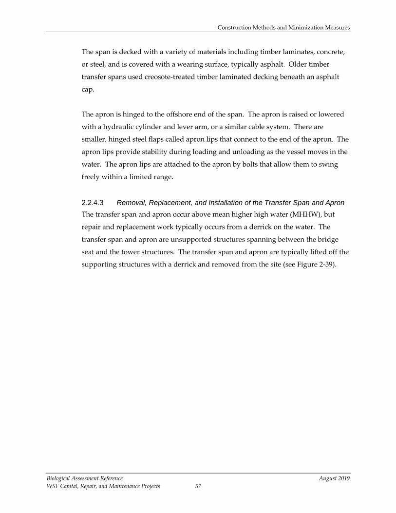
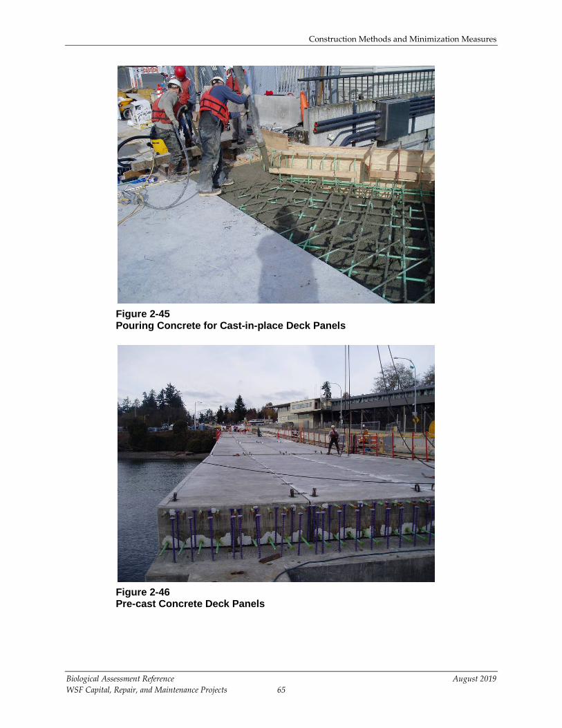
caps and deck panels may be cast in place (Figure 2-45) or pre cast (Figure 2-46).
Construction Methods and Minimization Measures
Biological Assessment Reference August 2019 WSF Capital, Repair, and Maintenance Projects 65
Figure 2-45 Pouring Concrete for Cast-in-place Deck Panels
Figure 2-46 Pre-cast Concrete Deck Panels

Construction Methods and Minimization Measures
Biological Assessment Reference August 2019 WSF Capital, Repair, and Maintenance Projects 66
2.2.7 Overhead Loading
Overhead loading facilities are pile-supported structures with an enclosed walkway
above (Figure 2-47). Of the 19 WSF terminals, six currently have overhead loading
facilities: Anacortes, Bainbridge Island, Bremerton, Edmonds, Kingston, and Seattle.
The overhead loading facilities at Anacortes, Edmonds, Kingston, Bremerton, and
Seattle are constructed of steel. The elevated walkway to the overhead loading
structure at Bainbridge Island is constructed of timber. The transfer span at the end of
the walkway is steel and the support structures are steel and concrete.

Jan
09, 2
012
11:5
2am
her
ikse
nK:
\Job
s\10
0016
-WSF
\100
0160
3\10
0016
03-B
A-00
1.dw
g FI
G 2-
46
Figure 2-47Typical Overhead Loading
WSF Biological Assessment Reference
SOURCE: Washington State Department of Transportation.

Construction Methods and Minimization Measures
Biological Assessment Reference August 2019 WSF Capital, Repair, and Maintenance Projects 68
Function Overhead loading structures provide direct pedestrian access to the passenger levels
of the vessel. These structures separate pedestrians from vehicular traffic, and allow
simultaneous loading of pedestrians and vehicles to improve safety and decrease
loading time.
Design Overhead loading facilities have a fixed walkway leading from the shore to a
moveable transfer span, loading cab, and gangway apron. The gangway apron is
connected to a cab. The apron and cab act much like a transfer span—the unit is
hinged on one end and raises and lowers with the tides to meet the upper deck of
the vessel. The apron is raised and lowered with a hydraulic or chain lifting system
connected to the cab. The elevation of the walkway is determined by the height of
the passenger deck level of the vessel servicing the route, and shoreline elevation.
The walkway is designed to meet Americans with Disabilities Act (ADA)
requirements. Typically, an overhead loading facility is about 20 feet higher than a
trestle.
The fixed portion of the timber overhead loading facility at Bainbridge Island is
designed much like a timber trestle. It is supported by rows of timber piling and
timber cross-bracing. Steel overhead loading facilities, such as those at Kingston and
Edmonds, are constructed of three to four 60-inch-diameter piling that support a
covered walkway. The seaward end of the cab is supported by either a tower system
or by a supercolumn (108 inches in diameter) containing an internal hydraulic
system. Both of these systems allow the end of the passenger overhead loading
structure to elevate or lower to meet the deck of the ferry vessel at any tide elevation.
The hydraulic system in the supercolumn is protected by a two-piece fiberglass
shroud, which is bolted onto the supercolumn (Figure 2-48).

Construction Methods and Minimization Measures
Biological Assessment Reference August 2019 WSF Capital, Repair, and Maintenance Projects 69
Figure 2-48 Supercolumn Supporting Overhead Loading Structure at the Kingston Terminal
Repair In-water repairs to overhead loading facilities include pile repair and/or installing
additional piling to shore up the structure and replacement of cross bracing. Repairs
to the tower system or hydraulics and protective fiberglass shroud (see Figure 2-48)
of a supercolumn are typically completed using a derrick with an overhead crane.
Installation
New overhead loading facilities are hydraulically supported and the pedestrian
transfer span can be raised and lowered to accommodate the tides and meet ADA
requirements. The hydraulic supercolumn supports the entire overwater structure.
The supercolumn is installed in the same way as hydraulic transfer spans, with a
drilled shaft foundation. Temporary pile supports may be needed to construct the
walkway structure until it is completed and can be supported by the supercolumn.
Fiberglass Shroud Needing Repair
Temporary Work Platform

Construction Methods and Minimization Measures
Biological Assessment Reference August 2019 WSF Capital, Repair, and Maintenance Projects 70
2.2.8 Bulkheads
Function WSF bulkheads are constructed of timber, steel sheet pile, riprap, or concrete walls
and are located beneath the trestle, acting as retaining walls to protect the shoreward
connection between the trestle and land. Many of the bulkheads at WSF terminals
occur above MHHW. These bulkheads must remain free of debris that can cause
damage to pile structures during high wind and wave action.
Design
Bulkheads are designed in a number of ways. Bulkheads commonly consist of sheet
piling driven into the ground or H-beam piling driven into the ground with either
timber or pre-cast concrete in between the piling, riprap, or lagging (horizontal
timber members in between vertical supports) (Figure 2-49). Large bulkheads or
those constructed in poor soil conditions may require installation of piles or small
diameter (36-inch) drilled shafts. Some bulkheads require support components,
referred to as tie-backs, which extend shoreward from the bulkhead to provide
additional support to the structure. Construction of concrete bulkheads usually
requires trenching to install either pre-cast concrete panels (constructed off site and
brought in for installation) or cast-in-place concrete lagging (concrete poured on
site). To prevent erosion, riprap has been installed in front of many WSF bulkheads.

Construction Methods and Minimization Measures
Biological Assessment Reference August 2019 WSF Capital, Repair, and Maintenance Projects 71
Figure 2-49 Timber and Steel Bulkheads
Repairs or Replacements to Bulkheads
Sheet pile bulkheads are susceptible to rust. A temporary repair method is to weld
replacement steel sheet metal over the rust holes and backfill any voids caused by
loss of soil through the holes. Whenever possible, the work is performed from the
upland area using land based equipment. Work performed from the waterside is
usually performed at low tide or from a floating work platform. A more permanent
repair method is to replace the bulkhead. Depending on the type of bulkhead,
replacement may require impact driving or vibratory installation of H-piles or
hollow steel piles, driving of sheet pile, or installation of concrete panels.
Timber bulkheads can be replaced or repaired by removing and replacing lagging
with new pieces of timber. This work is also performed at low tide.
2.2.9 Temporary Structures
Two types of temporary structures are described in this section: structures required to
provide passenger-only service or other service during scheduled construction that

Construction Methods and Minimization Measures
Biological Assessment Reference August 2019 WSF Capital, Repair, and Maintenance Projects 72
results in the temporary closure of a facility, and structures that are installed under
urgent or emergency situations.
Structures to Provide Limited Service Closure of facilities is occasionally required during larger replacement projects such
as removal of transfer spans, construction of towers, and construction of wingwalls.
In these instances, WSF is responsible for providing some level of service to the
public during closures. In the event of a complete shutdown of vessel operations,
WSF typically provides passenger-only service between existing WSF terminals or
other nearby facilities. To provide service, ADA-accessible floats and ramps may be
used. The longest closure of a WSF facility to date has been 3 weeks, and passenger-
only service was provided for the duration of the closure. Temporary structures
used to provide interim service are removed shortly after service is resumed.
Structures to Maintain Regular Service Structures such as towers, wingwalls, and (most frequently) dolphins are prone to
catastrophic damage from hard landings caused by weather conditions or
malfunctioning equipment on a vessel. In these instances, WSF may need to install a
temporary structure to maintain vessel operations while a permanent structure can
be designed, materials procured, money reallocated, and normal contracting
procedures completed. Temporary structures are most often dolphins, and are
generally a cluster of steel or ACZA-treated timber piles. Temporary structures
generally contain fewer than 25 piles and sometimes as few as six piles. Under these
situations, WSF aims to complete the permanent repair as quickly as possible, but
due to factors such as budget constraints, availability of materials, availability of
labor to engineer the structures, and limited construction windows, temporary
structures may not be replaced for up to 2 years.
Structures to Maintain Operation During Construction Temporary structures such as transfer spans and towers may be needed to maintain
operation during construction at terminals. The nature of these structures is project-
dependent and the construction methods are the same as for similar permanent
structures.

Construction Methods and Minimization Measures
Biological Assessment Reference August 2019 WSF Capital, Repair, and Maintenance Projects 73
Structures Used for Construction Temporary work platforms are occasionally used to allow access to construction
areas, or to guide placement of new structures (see Figure 2-50). Examples of these
structures include the temporary work platforms used for installation of rock
anchors on Lopez Island and the platform used to guide the placement of a
replacement dolphin on Bainbridge Island.
The installation of work platforms often requires placement of temporary piles for
support (Figure 2-51).
Figure 2-50 Temporary Work Platform

Construction Methods and Minimization Measures
Biological Assessment Reference August 2019 WSF Capital, Repair, and Maintenance Projects 74
Figure 2-51 Work Platform Supported by Temporary Steel Piles
2.3 Minimization Measures
The following MMs will be employed during all construction at WSF facilities. General
MMs used for all construction practices are presented in Section 2.3.1, followed by specific
MMs for individual activities in Sections 2.3.2 through 2.3.5. Some of these MMs apply to
several different activities and are listed multiple times in these sections.
These MMs have been developed and are routinely used by WSF during repair,
replacement, and maintenance activities at WSF terminals. The MMs are intended to avoid
and minimize potential effects to ESA-listed species and designated critical habitat.
The language in each MM is included in the Contract Plans and Specifications for specific
projects and must be agreed upon by the contractor prior to any construction activities.
Upon signing the contract, it becomes a legal agreement between the contractor and WSF.
Failure to follow the prescribed MMs is a contract violation.

Construction Methods and Minimization Measures
Biological Assessment Reference August 2019 WSF Capital, Repair, and Maintenance Projects 75
WSF policy and construction administration practice is to have a WSF inspector on site
during construction. The role of the inspector is to ensure contract compliance. The
inspector and the contractor each have a copy of the Contract Plans and Specifications on
site and are aware of all requirements. The inspector is also trained in environmental
provisions and compliance.
2.3.1 General Minimization Measures for All Construction Activities
All WSF construction is performed in accordance with the current WSDOT Standard
Specifications for Road, Bridge, and Municipal Construction. Special Provisions
contained in preservation and repair contracts are used in conjunction with, and
supersede, any conflicting provisions of the Standard Specifications.
WSF activities are subject to federal, state, and local permit conditions. WSF uses the
best guidance available (e.g., best management practices [BMPs] and MMs) to
accomplish the necessary work while avoiding and minimizing environmental effects
to the greatest extent possible.
WSF policy and construction administration is to have at least one WSF inspector on
site during construction. The role of the inspector will be to ensure contract and
permit compliance. The inspector and contractor each will have a copy of the Contract
Plans and Specifications on site and will be aware of all permit requirements. In
addition, depending on the specific project, environmental staff may be present for
monitoring and compliance.
WSF must comply with all Washington State Department of Ecology (Ecology) water
quality regulations. General and specific conditions to protect water quality that apply
to the project shall be reviewed with all contractors prior to the start of the project, and
kept on the job site at all times during construction.
Timing restrictions are used to avoid in-water work when ESA-listed species are most
likely to be present. Work windows are typically imposed by the Corps and/or
Services if data indicates that listed species are present in the area, and by WDFW if
forage fish spawning is known to occur near the terminals.

Construction Methods and Minimization Measures
Biological Assessment Reference August 2019 WSF Capital, Repair, and Maintenance Projects 76
The contractor will be advised that eelgrass (Zostera marina L.) beds are protected
under local, state, and federal law. When work will occur near eelgrass beds, WSF will
provide plan sheets showing eelgrass boundaries to the contractor. The contractor
shall exercise extreme caution when working in the area indicated on the plans as
“Eelgrass Beds.” The contractor shall adhere to the following restrictions during the
life of the contract. The contractor shall not:
1. Place derrick spuds or anchors in the area designated as “Eelgrass.”
2. Shade the eelgrass beds for a period of time greater than 3 consecutive days
during the growing season (generally March through September).
3. Allow debris or any type of fuel, solvent, or lubricant in the water.
4. Perform activities that could cause significant levels of sediment to cover the
eelgrass beds.
5. Conduct activities that may cause scouring of sediments within the eelgrass beds
or other types of sediment transfer out of or into the eelgrass beds.
Any damage to eelgrass beds or substrates supporting eelgrass beds that results from a
contractor’s operations will be repaired at the contractor’s expense.
WSF will obtain Hydraulic Project Approval (HPA) from WDFW and a Shoreline
Substantial Development Permit (SSDP) or Permit Exemption from the local
jurisdiction for in-water projects and the contractor will follow the conditions of these
permits. HPA and SSDP or Permit Exemption requirements will be listed in the
contract specifications for the contractor to agree to prior to construction and the HPA
will be attached to the contract such that conditions of the HPA and SSDP are made
part of the contract.
Additional general MMs for all activities described in this document include:
• The contractor shall be responsible for the preparation of a Spill Prevention,
Control, and Countermeasures (SPCC) Plan to be used for the duration of the
project. The plan shall be submitted to the project engineer prior to the
commencement of any construction activities. A copy of the SPCC Plan with any
updates will be maintained at the work site by the contractor.

Construction Methods and Minimization Measures
Biological Assessment Reference August 2019 WSF Capital, Repair, and Maintenance Projects 77
- The SPCC Plan shall identify construction planning elements, and recognize
potential spill sources at the site. The SPCC shall outline BMPs, responsive
actions in the event of a spill or release, and notification and reporting
procedures. The SPCC shall also outline contractor management elements
such as personnel responsibilities, project site security, site inspections, and
training.
- The SPCC will outline what measures shall be taken by the contractor to
prevent the release or spread of hazardous materials, either found on site and
encountered during construction but not identified in contract documents, or
any hazardous materials that the contractor stores, uses, or generates on the
construction site during construction activities. These items include, but are
not limited to, gasoline, oils, and chemicals. Hazardous materials are defined
in Regional Code of Washington (RCW) 70.105.010 under “hazardous
substance.”
- The contractor shall maintain, at the job site, the applicable spill response
equipment and material designated in the SPCC Plan.
• No petroleum products, fresh cement, lime, concrete, chemicals, or other toxic or
deleterious materials shall be allowed to enter surface waters.
• WSF will comply with water quality restrictions imposed by Ecology (Chapter
173-201A WAC), which specify a mixing zone beyond which water quality
standards cannot be exceeded. Compliance with Ecology’s standards is intended
to ensure that fish and aquatic life are being protected to the extent feasible and
practicable.
• If beach access is required, use of equipment on the beach area shall be held to a
minimum and confined to designated access corridors that minimize foot traffic
on the upper beach.
• Barge operations shall be restricted to tide elevations adequate to prevent
grounding of the barge.
• Wash water resulting from washdown of equipment or work areas shall be
contained for proper disposal, and shall not be discharged into state waters
unless authorized through a state discharge permit.
• Equipment that enters the surface water shall be maintained to prevent any
visible sheen from petroleum products appearing on the water.

Construction Methods and Minimization Measures
Biological Assessment Reference August 2019 WSF Capital, Repair, and Maintenance Projects 78
• There shall be no discharge of oil, fuels, or chemicals to surface waters, or onto
land where there is a potential for reentry into surface waters.
• No cleaning solvents or chemicals used for tools or equipment cleaning shall be
discharged to ground or surface waters.
• The contractor shall regularly check fuel hoses, oil drums, oil or fuel transfer
valves, fittings, etc. for leaks, and shall maintain and store materials properly to
prevent spills.
• Projects and associated construction activities will be designed so potential
effects to species and habitat are avoided and minimized.
2.3.2 Pile Removal and Demolition of Structures
MMs to be employed during pile removal and demolition of structures include:
• A containment boom surrounding the work area will be used during creosote-
treated pile removal to contain and collect any floating debris and sheen,
provided that the boom does not interfere with vessel operations. The boom will
remain in place until all oily material and floating debris have been collected and
all sheens have dissipated. The contractor will also retrieve any debris generated
during construction, which will be properly disposed of at an approved upland
location.
• The contractor will have oil-absorbent materials on site to be used in the event of
a spill if any oil product is observed in the water.
• All creosote-treated material, pile stubs, and associated sediments will be
disposed of by the contractor in a landfill that meets the liner and leachate
standards of the Minimum Functional Standards, Chapter 173-304 WAC. The
contractor will provide receipts of disposal to the WSF project engineer.
• Removed piles, stubs, and associated sediments (if any) shall be contained on a
barge. If piles are placed directly on the barge and not in a container, the storage
area shall consist of a row of hay or straw bales, filter fabric, or similar BMP
placed around the perimeter of the barge.
• Excess or waste materials will not be disposed of or abandoned waterward of
Ordinary High Water (OHW) or allowed to enter waters of the state, as per WAC
220-110-070. Waste materials will be disposed of in a landfill. Hazardous waste
and treated wood waste will be disposed of by the contractor in a landfill that
Construction Methods and Minimization Measures
Biological Assessment Reference August 2019 WSF Capital, Repair, and Maintenance Projects 79
meets the liner and leachate standards of the Minimum Functional Standards,
Chapter 173-304 WAC.
• Piling that break or are already broken below the waterline will be removed with
a clamshell bucket. To minimize disturbance to bottom sediments and
splintering of piling, the contractor will use the minimum size bucket required to
pull out piling based on pile depth and substrate. The clamshell bucket will be
emptied of piling and debris on a contained barge before it is lowered into the
water. If the bucket contains only sediment, the bucket will remain closed, be
lowered to the mudline, and opened to redeposit the sediment.
• Demolition and construction materials shall not be stored where high tides, wave
action, or upland runoff can cause materials to enter surface waters.
2.3.3 Pile Installation, Pile Repair, and Installation of Structures
MMs to be employed during pile installation, pile repair, and installation of structures
include:
• The vibratory hammer method will be used to the extent possible to drive steel
piles to minimize noise levels.
• A bubble curtain or other noise attenuation device will be employed during
impact installation or proofing of steel piles unless the piles are driven in the dry.
• WSF will comply with water quality restrictions imposed by Ecology (Chapter
173-201A WAC), which specifies a mixing zone beyond which water quality
standards cannot be exceeded. Compliance with Ecology’s standards is intended
to ensure that fish and aquatic life are protected to the extent feasible and
practical.
• Creosote-treated timber piling shall be replaced with non-creosote-treated piling.
• The contractor will be required to ensure that wet concrete does not come in
contact with marine waters. Forms for any concrete structure will be constructed
to prevent leaching of wet concrete. Forms will remain in place until concrete is
cured.
• The tube used to fill steel pilings with concrete or to grout rock anchors will be
placed toward the bottom of the piling to prevent splashing and concrete
overflow.

Construction Methods and Minimization Measures
Biological Assessment Reference August 2019 WSF Capital, Repair, and Maintenance Projects 80
• During grouting of rock anchors, the bottom of the pile will be sealed by the
sediment it has been driven into or, if the sediment layer is too thin, by plastic
and sandbags to ensure no concrete escapes from the base of the pile.
• For installation of drilled shafts, sediments and slurry will be completely
contained within the casing during construction. The sediments removed will be
contained for upland disposal, as will the drilling slurry.
• The contractor will be required to retrieve any floating debris generated during
construction. Any debris in the containment boom will be removed by the end
of the work day or when the boom is removed, whichever occurs first. Retrieved
debris will be disposed of at an upland disposal site.
• Whenever activities that generate sawdust, drill tailings, or wood chips from
treated timbers are conducted, tarps or other containment material shall be used
to prevent debris from entering the water. If tarps cannot be used (because of the
location or type of structure), a containment boom will be placed around the
work area to capture debris and cuttings.
• Excess or waste materials will not be disposed of or abandoned waterward of
OHW or allowed to enter waters of the state.
• Water inside the form used for pile repairs will be drained to the water elevation
outside the form before concrete is poured.
• Steel, plastic/steel, concrete, or ACZA-treated wood piling will be used. No
creosote-treated timber piling will be used.
• ACZA-treated wood will be treated using the April 3, 2012 version of the BMPs
for the Use of Treated Wood in Aquatic and Wetland Environments; Western
Wood Preservers Institute.
• All piling, lumber, and other materials treated with preservatives shall be
sufficiently cured to minimize leaching into the water or sediment.
• Hand tools or a siphon dredge will be used to excavate around piles to be
replaced.
2.3.4 Temporary Structures
MMs to be employed during installation of temporary structures include:
• Temporary structures associated with facility closures during construction will
be removed before the contractor demobilizes from the site.

Construction Methods and Minimization Measures
Biological Assessment Reference August 2019 WSF Capital, Repair, and Maintenance Projects 81
• Temporary structures installed to maintain existing service to the facility will be
replaced with the permanent structure within 2 years of installation.
• If temporary floats are installed to provide passenger-only service in areas
adjacent to eelgrass beds, floats will be designed to avoid shading of eelgrass
beds, or will be installed in water depths of at least -20 feet MLLW to prevent
scouring of eelgrass beds.
• WSF will develop operational criteria for temporary vessels providing
passenger-only service, including maximum horsepower ratings, propeller
diameters, and propeller depth to centerline thresholds that the provider of the
passenger-only service must meet to operate at temporary passenger-only
facilities, to prevent scouring of the seabed.
2.3.5 Dredging
MMs to be employed during dredging include:
• Dredged material will be contained with BMPs such as ecology blocks, filter
fabric, and/or straw bales and disposed of in an approved in-water disposal site
or upland location, or reused if reuse has been approved.
• WSF will comply with water quality restrictions imposed by Ecology (Chapter
173-201A WAC), which specifies a mixing zone beyond which water quality
standards cannot be exceeded. Compliance with Ecology’s standards is intended
to ensure that fish and aquatic life are protected to the extent feasible and
practical.
• Dredging will be done at a slow and controlled pace to minimize turbidity.