Embed Size (px)
Citation preview

1 of 14888-24-205-G-06 rev. H • 05/16
< 65 lbs. (29.5 kg)
Reduce.Reuse.Recycle
WorkFit-D
EN
GL
ISH
Max weight 65 lbs – 29.5 kgCAUTION: DO NOT EXCEED MAXIMUM LISTED
WEIGHT CAPACITY. SERIOUS INJURY OR PROP-
ERTY DAMAGE MAY OCCUR!

2 of 14888-24-205-G-06 rev. H • 05/16
826-901-00
WARNING
Moving Parts Can Crush And Cut
IMPACT HAZARD
Failure to heed this warning may result inserious personal injury or property damage!
For More information and instructions visit www.ergotron.comor contact Ergotron Customer Care at 1-800-888-8458.
Minimize Lift Strength BEFORE:- Removing Mounted Equipment
andInsert 4 Stop Screws BEFORE:
- Shipping or Storing (i.e. when Desk is not upright).To Minimize Lift Strength
Refer to installation manual for instructions onhow to minimize lift strength.
To Insert 4 Stop ScrewsRefer to installation manual for instructions on
installing stop screws.
EN
GL
ISH
These symbols alert users of a safety condition that
demands attention. All users should be able to
recognize and understand the signifi cance of the fol-
lowing Safety Hazards if encountered on the product
or within the documentation. Children who are not
able to recognize and respond appropriately to Safety
Alerts should not use this product without adult
supervision!
Hazard Symbols Review Symbol Signal Word Level of Hazard
NOTEA NOTE indicates important information that helps you
make better use of this product.
CAUTION
A CAUTION indicates either potential damage to
hardware or loss of data and tells you how to avoid the
problem.
WARNINGA WARNING indicates either potential for property dam-
age, personal injury, or death.
ELECTRICAL
An Electrical indicates an impending electrical hazard
which, if not avoided, may result in personal injury, fi re
and/or death.
Safety
Important! You will need to adjust this product after installation is complete. Make sure all your equipment is properly installed on the product before attempting adjustments. This product should move smoothly and easily through the full range of motion and stay where you set it. If movements are too easy or diffi cult or if product does not stay in desired positions, follow the adjustment instructions to create smooth and easy movements. Depending on your product and the adjustment, it may take many turns to notice a diff erence. Any time equipment is added or removed from this product, resulting in a change in the weight of the mounted load, you should repeat these adjustment steps to ensure safe and optimum operation.

3 of 14888-24-205-G-06 rev. H • 05/16
1 2
3
4
EN
GL
ISH
WARNING! TIPPING HAZARD!
When mounting accessories to the
WorkFit-D, they must stay within the foot
print. Do not mount accessories past the
front and rear worksurface! Failure to fol-
low this warning may result in equipment
damage and or personal injury.
WARNING! Stop screws are pre-installed in this product to secure it in the compressed position during shipping and installation. DO NOT REMOVE THESE SCREWS UNTIL INSTRUCTED TO DO SO IN THESE INSTRUCTIONS. Make sure these screws are in place before starting installation. Failure to follow these instructions may cause lift engine to expand rapidly and may result in equipment damage and or personal injury. If any of the 4 stop screws are not installed in these locations, contact customer care before continuing with installation.
DO NOT REMOVE SCREWS!
DO NOT REMOVE SCREWS!
IMPORTANT!Save these stop screws and instructions. Install stop screws when shipping or storing this product. Failure to follow these instructions may cause lift engine to expand rapidly and may result in equipment damage and or personal injury.
WARNINGKeep Brake Cables Away from
Sync Rod and Crossbars During Installation!
Failure to keep the brake cables away from sync rod and crossbars may restrict lift
motion and may cause equipment damage or personal injury! Refer to instruction
manual for more information.

4 of 14888-24-205-G-06 rev. H • 05/16
1/4”
14mm
1x1x
M5 x 6 mm
M2.9 x 8 mm
17x
2x
3x 3x
16x
2x
1x
1x
EN
GL
ISH
Components
Tools Needed
Sync Rod
Crossbars
# 12-14 Wood Screw

5 of 14888-24-205-G-06 rev. H • 05/16
8x
1
2
3
EN
GL
ISH
Place the worksurface on a clean fl oor with
the top side facing down.
Carefully position the leg with the hand
brake on the right end of the worksurface.
Place the other leg on the left end.
Attach one end of the sync rod to the
right leg as illustrated. Make sure the
brake cables don’t loop around the sync
rod. See Warning, right.
Set-up Steps
NOTE: The brake cable is attached to both legs. Take care when re-moving the legs from the packaging to avoid damaging or pulling the brake cable from the legs.
NOTE: Do not fully
insert the screws
into the worksurface
at this time. Leave
approximately 1/8”
space.
Front =2 screwsMiddle = 3 screws
Rear = 3 screws
# 12-14 Wood Screw
Front Edge of Worksurface
Rear Edge of Worksurface
Set the right leg (with hand brake) upright on the
worksurface.
Partially insert 3 of the provided #12-14 wood
screws at the rear of the leg, 3 near the middle of
the leg and 2 at the front of the leg.
WARNINGKeep Brake Cables Away from
Sync Rod and Crossbars During Installation!
Failure to keep the brake cables away from sync rod and crossbars may restrict lift
motion and may cause equipment damage or personal injury! Refer to instruction
manual for more information.

6 of 14888-24-205-G-06 rev. H • 05/16
9x
16x
M5 x 6 mm
6
5
4
7
WARNINGKeep Brake Cables Away from
Sync Rod and Crossbars During Installation!
Failure to keep the brake cables away from sync rod and crossbars may restrict lift
motion and may cause equipment damage or personal injury! Refer to instruction
manual for more information.
EN
GL
ISH
Use a Phillips screwdriver to insert the provided M5x6
mm screws into the two crossbars connecting the left
and right legs. Make sure the brake cables don’t
loop around the crossbars.
Tighten the screws slightly one at a time
and repeat to ensure that the tension
on every screw is equal.
Partially insert 9 of the provided #12-14 wood screws
in the left leg and worksurface.
Set the left leg (without
hand brake) upright on the
worksurface.
Attach the left end of the
sync rod to the left leg.
Make sure the brake cables
don’t loop around the sync
rod. See Warning, right.
Use a Phillips screwdriver to tighten
down the screws attaching the legs to
the worksurface.
NOTE: Do not overtighten screws. overtightening screws may result in stripping the holes and may cause the installation to be unsafe.
NOTE: Do not overtighten screws. overtightening screws may result in stripping the holes and may cause the installation to be unsafe.
NOTE: Do not
fully insert
the screws
into the work-
surface at this
time. Leave
approximate-
ly 1/8” space.
Set-up Steps
Front =2 screwsMiddle = 3 screws
Rear = 3 screws
# 12-14 Wood Screw

7 of 14888-24-205-G-06 rev. H • 05/16
3x 3x
M2.9 x 8 mm
2x
8
9
EN
GL
ISH
Capture the brake cable in the cable clip as
illustrated, then use a Phillips screwdriver
to attach the cable clips to bottom of work
surface with the provided M2.9 x 8 mm screws.
Using the 2 provided cable ties, attach brake cable
to the legs leaving as much slack in cable as possible
between the cable tie and the leg to allow desk top to
raise up unrestricted.
NOTE: Leave as much slack in cable as possible between the cable tie and the leg to allow desk top to raise up unrestricted. Failure to follow this may result in equipment damage.
Set-up Steps

8 of 14888-24-205-G-06 rev. H • 05/16
10
11
EN
GL
ISH
Set the desk upright onto its legs.
CAUTION!
LIFT HAZARD!
Two persons are required for this step. Failure to follow this warning may result in equipment damage and or personal injury.
Adjust the riser on each leg and check with a level to
make sure the work surface is even.
Spin Right to Lower.Spin Left to Raise.
Set-up Steps

9 of 14888-24-205-G-06 rev. H • 05/16
12
1
2
EN
GL
ISH
Remove the 4 brake stop screws before installing equipment.
Remove the 2 stop screws from the legs then the 2 stop screws from
the brake to allow the worksurface to raise and lower.
After you remove the 4 brake stop
screws, release the hand brake
(on the right leg) and move the
worksurface up to highest level.
Set-up Steps
IMPORTANT!Save these stop screws and instructions. Install stop screws when shipping or storing this product. Failure to follow these instructions may cause lift engine to expand rapidly and may result in equipment damage and or personal injury.

10 of 14888-24-205-G-06 rev. H • 05/16
14
13
826-901-00
WARNING
Moving Parts Can Crush And Cut
IMPACT HAZARD
Failure to heed this warning may result inserious personal injury or property damage!
For More information and instructions visit www.ergotron.comor contact Ergotron Customer Care at 1-800-888-8458.
Minimize Lift Strength BEFORE:- Removing Mounted Equipment
andInsert 4 Stop Screws BEFORE:
- Shipping or Storing (i.e. when Desk is not upright).To Minimize Lift Strength
Refer to installation manual for instructions onhow to minimize lift strength.
To Insert 4 Stop ScrewsRefer to installation manual for instructions on
installing stop screws.
EN
GL
ISH
Adjustment Step
Install all equipment.
CAUTION! Make sure you leave 20” (508mm) of slack in all equipment cables to allow the worksurface to raise up it’s full 20” (508mm). Failure to allow enough slack in equipment cables may cause cables to get pulled, equipment to fall off desk and may result in product damage and or personal injury.
Set-up Steps
IMPORTANT! This product will need tension adjustments once installation is complete. Make sure all equipment is properly installed on the product before attempting range of motion or tension adjustments. Any time equipment is added or changed on this product resulting in a diff erent mounted weight, you should repeat the adjustment steps to ensure safe and optimum operation. This product should move smoothly and easily through the full range of motion. If movement is diffi cult follow the adjustment instructions to loosen or tighten the tension to create a smooth, easy motion. Depending on your product and the adjustment, it may take many turns to notice a diff erence.

11 of 14888-24-205-G-06 rev. H • 05/16
=
14mm
14
EN
GL
ISH
Release the hand brake (on the right leg) and move
the worksurface up to highest level.
Push in the cover located behind each leg to access
the adjustment point.
Maintain equal amount of tension on both legs by
alternating the tension adjustment from one leg to
the other using a 14mm socket drill.
Adjustment Step
Spin left to loosen tension
(for lighter loads).
Spin right to tighten tension
(for heavier loads).
Make sure
covers are fully
closed before
lowering the
worksurface.
NOTE: The covers on the legs will not open unless the worksurface has been lifted to it’s full height. The worksurface will not lower unless the covers have been completely closed.
WARNING! DO NOT tip desk over to adjust. Only perform adjustment while desk is upright.
Failure to follow these instructions may cause the lift engine to expand rapidly and may result in
equipment damage and or personal injury.
12 of 14888-24-205-G-06 rev. H • 05/16
=
14mm
EN
GL
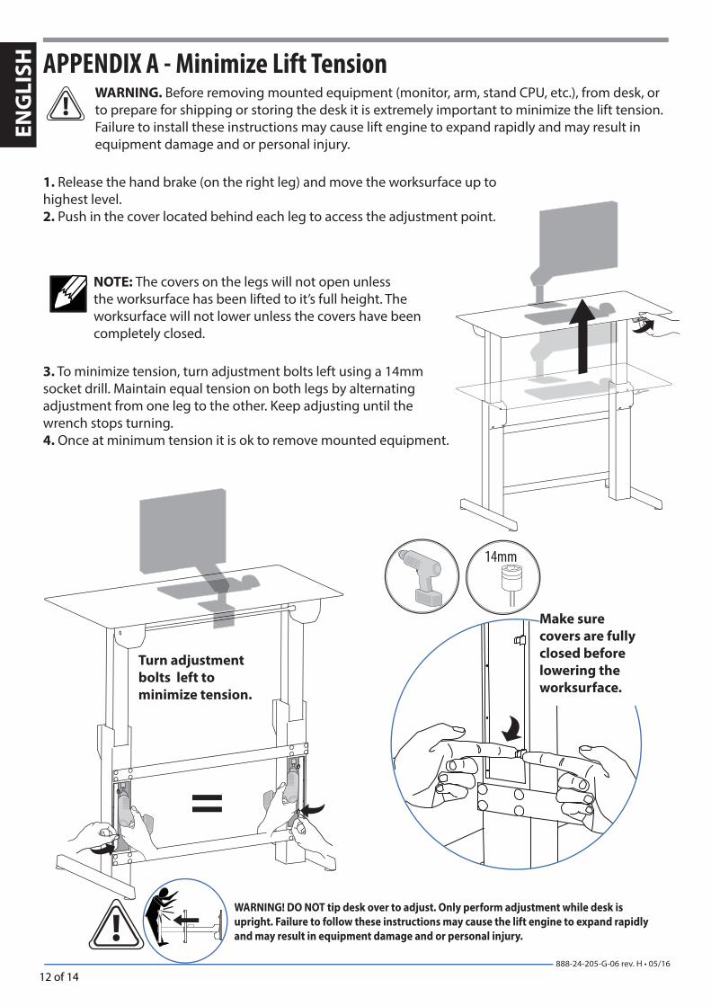
ISH APPENDIX A - Minimize Lift Tension
WARNING. Before removing mounted equipment (monitor, arm, stand CPU, etc.), from desk, or to prepare for shipping or storing the desk it is extremely important to minimize the lift tension. Failure to install these instructions may cause lift engine to expand rapidly and may result in equipment damage and or personal injury.
Turn adjustment
bolts left to
minimize tension.
WARNING! DO NOT tip desk over to adjust. Only perform adjustment while desk is
upright. Failure to follow these instructions may cause the lift engine to expand rapidly
and may result in equipment damage and or personal injury.
Make sure
covers are fully
closed before
lowering the
worksurface.
NOTE: The covers on the legs will not open unless the worksurface has been lifted to it’s full height. The worksurface will not lower unless the covers have been completely closed.
1. Release the hand brake (on the right leg) and move the worksurface up to highest level.2. Push in the cover located behind each leg to access the adjustment point.
3. To minimize tension, turn adjustment bolts left using a 14mm socket drill. Maintain equal tension on both legs by alternating adjustment from one leg to the other. Keep adjusting until the wrench stops turning.4. Once at minimum tension it is ok to remove mounted equipment.

13 of 14888-24-205-G-06 rev. H • 05/16
1
2
EN
GL
ISH
APPENDIX B - Inserting Stop ScrewsWARNING. Before shipping or storing the desk, or in cases where the desk is placed on it’s back or side*, it is extremely important that the 4 stop screws be re-inserted. Failure to follow these instructions may cause lift engine to expand rapidly and may result in equipment damage and or personal injury.
1. Follow instructions in Appendix A to minimize lift tension.
2. Push the desk down to its lowest position.
3. Insert 2 stop screws at the bottom of each leg.
4. Insert the other 2 stop screws on each side of the hand brake located on the right side of the worksurface.
5. Once the 4 stop screws have beeninstalled the desk can be shippedor stored.
* Placing the desk on its back or side is not recommended.

14 of 14888-24-205-G-06 rev. H • 05/16
Set Your Workstation to Work For YOU!
Confi gure su estación de trabajo para que trabaje para USTED.
Ajustez votre station de travail en fonction de VOS besoins !
Richten Sie Ihren Arbeitsplatz so ein, dass er für SIE arbeitet!
Stel uw werkstation zo in dat het voor U werkt!
Approntare la stazione di lavoro nella posizione ergonomica ottimale.
一人ひとりにピッタリのワークステーション! 按照您自身的需要设置工作站!
Learn more about ergonomic computer use at:Más información sobre el uso ergonómico de ordenadores:
Apprenez-en plus sur l’utilisation ergonomique d’un ordinateur sur :Weitere Informationen zur ergonomischen Computernutzung fi nden Sie unter:
Leer meer over ergonomisch computergebruik op:Per ulteriori informazioni sull’uso ergonomico del computer:
人間工学的なコンピュータの使用法については次のサイトを参照してください想进一步了解以符合人体工程学的方式使用计算机的知识,请访问:
www.computingcomfort.org Height Position top of screen slightly below eye level. Position keyboard at about elbow height with wrists fl at. Distance Position screen an arm's length from face—at least 20” (508mm). Position keyboard close enough to create a 90˚ angle in elbow. Angle Tilt screen to eliminate glare. Tilt the keyboard back 10° so that your wrists remain fl at.
Altura Coloque el borde superior de la pantalla ligeramente por debajo de la altura de sus ojos. Coloque el teclado aproximadamente a la altura de los codos con las muñecas planas. Distancia Coloque la pantalla a una distancia de un brazo desde la cara, esto es, unos 50 cm (20 pulgadas). Coloque el teclado lo sufi cientemente cerca para que el codo forme un ángulo de 90º. Ángulo Incline la pantalla para eliminar los refl ejos. Incline el teclado 10º hacia atrás para que las muñecas sigan en posición plana.
Hauteur Positionnez l’écran du haut légèrement en dessous du niveau du regard. Positionnez le clavier à peu près à la même hauteur que vos coudes, pour que vos poignets soient à plat. Distance Positionnez l’écran à un bras de distance de votre visage, à au moins 508 mm (20 pouces). Positionnez le clavier assez près pour que vos coudes forment un angle de 90°. Angle Inclinez l’écran pour ne pas être ébloui. Inclinez le clavier vers l’arrière de 10° pour que vos poignets soient à plat.
Höhe Positionieren Sie die obere Kante des Bildschirms knapp unter Augenhöhe. Positionieren Sie die Tastatur bei fl ach aufgelegten Handgelenken auf Ellenbogenhöhe. Abstand Positionieren Sie den Bildschirm mindestens eine Armlänge (50 cm) von Ihrem Gesicht entfernt. Positionieren Sie die Tastatur nahe genug, um einen Ellenbogenwinkel von 90 ˚ zu ermöglichen. Winkel Neigen Sie den Bildschirm so, dass ein Spiegeleff ekt vermieden wird. Neigen Sei die Tastatur um 10 ° nach hinten, sodass Ihre Handgelenke fl ach aufl iegen.
Hoogte Zet de bovenkant van het scherm iets boven ooghoogte. Plaats het toetsenbord op ongeveer ellebooghoogte met de polsen plat. Afstand Plaats het scherm op een armlengte van uw gezicht — op ten minste 508 mm (20 in). Zet uw toetsenbord zo dichtbij dat u een hoek van 90° in de ellebogen hebt. Hoek Kantel het scherm om weerspiegeling te elimineren. Kantel het toetsenbord 10° naar achteren, zodat uw polsen plat blijven liggen.
Altezza Posizionare la parte superiore dello schermo leggermente sotto il livello degli occhi. Posizionare la tastiera circa all’altezza dei gomiti, in modo che i polsi siano piatti. Distanza Posizionare lo schermo a un braccio di distanza dal viso, almeno a 20" (508 mm) di distanza. Posizionare la tastiera affi nché sia abbastanza vicina da costringere i gomiti a un angolo di 90˚. Angolazione Inclinare lo schermo in modo da eliminare i rifl essi. Inclinare la tastiera indietro di 10° in modo che i polsi rimangano piatti.
高さ スクリーンの上端が目よりわずかに下に来るようにします。 キーボードが、手首を水平に伸ばした状態でひじとほぼ同じ高さに来るようにします。 距離 スクリーンを顔から腕の長さ分(少なくとも508mm)離します。 ひじが直角になる位置にキーボードを置きます。 角度 反射光をなくすようにスクリーンの角度を調整します。 キーボードを後方に 10° 傾けて、手首が水平になるようにします。
高度 屏幕顶端的位置要稍低于视线高度。 将键盘放置在大约肘部的高度并且手腕要能放平。 距离 将屏幕摆放在距离面部一臂长的位置——至少 508mm (20”)。 键盘的位置要够近,以使肘部形成直角。 角度 倾斜屏幕以消除眩光。 将键盘向后倾斜 10 度,使手腕能保持放平。
To Reduce FatigueBreathe - Breathe deeply through your nose.Blink - Blink often to avoid dry eyes.Break • 2 to 3 minutes every 20 minutes• 15 to 20 minutes every 2 hours.
Para reducir la fatigaRespirar - Respire hondo por la nariz.Parpadear - Parpadee a menudo para que no se sequen los ojos.Descansar • 2 o 3 minutos cada 20 minutos• 15 o 20 minutos cada 2 horas.
Pour réduire la fatigueRespirez - Respirez profondément par votre nez.Clignez des yeux - Clignez souvent des yeux pour ne pas avoir les yeux secs.Faites des pauses • 2 à 3 minutes toutes les 20 minutes• 15 à 20 minutes toutes les 2 heures.
Vermeiden von ErmüdungserscheinungenAtmen - Atmen Sie tief durch die Nase ein und aus.Blinzeln - Blinzeln Sie so oft wie möglich, um trockene Augen zu vermeiden.Pausen • Machen Sie alle 20 Minuten eine Pause von 2-3 Minuten• Machen Sie alle 2 Stunden eine Pause von 15-20 Minuten.
Om vermoeidheid te verminderenAdemen - Adem diep door uw neus in en uit.Knipperen - Knipper regelmatig om droge ogen te vermi-jden.Pauzes nemen • 2 tot 3 minuten elke 20 minuten• 15 tot 20 minuten elke 2 uur.
Per ridurre l’aff aticamentoRespirazione - Respirare profondamente dal naso.Battito delle palpebre - Battere spesso le palpebre per evitare che gli occhi si asciughino.Pause • Fare una pausa di 2 - 3 minuti ogni 20 minuti• Fare una pausa di 15 - 20 minuti ogni 2 ore.
疲れを軽減する方法呼吸 - 鼻から深く呼吸します。まばたき - 目の乾燥を防ぐために頻繁にまばたきしてください。休憩 • 20分ごとに2~3分• 2時間ごとに15~20分
为了减轻疲劳呼吸 - 通过鼻子深呼吸。眨眼 - 经常眨眼可避免眼睛干涩。休息 • 每隔 20 分钟休息 2 至 3 分钟• 每隔 2 小时休息 15 至 20 分钟.
© 2016 Ergotron, Inc. All rights reserved.
EN
GL
ISH