Embed Size (px)
Citation preview
Woodhouse Colliery
Buried Conveyor Route Pipe Jack Installation
1
WOODHOUSE COLLIERY – BURIED CONVEYOR
CLIENT: WEST CUMBRIA MINING
Work Package: Conveyor Route Pipe Jack Installation
Woodhouse Colliery
Buried Conveyor Route Pipe Jack Installation
2
1.0 Issue and Revision Control
Distribution and revision control are managed under the Electronic Document
Management System, with the latest revision displayed. This document is uncontrolled
when printed.
Revision History
Rev No Date Summary of Changes Section Number
P01 19/04/2021 First issue
P02 4/08/2021 Review and update minor errata 8.1, 9.1, 13
Woodhouse Colliery
Buried Conveyor Route Pipe Jack Installation
3
2.0 Contents
1.0 Issue and Revision Control ....................................................................................................... 2
3.0 Work Package Plan Conformance Check List .......................................................................... 4
4.0 Purpose of Works Package Plan (WPP) ................................................................................... 5
5.0 Legislation & Standards ............................................................................................................ 5
6.0 Description of Works ................................................................................................................ 5
7.0 Work Location .......................................................................................................................... 6
8.0 Work Method ............................................................................................................................ 8
8.1 Method Overview .................................................................................................................. 8
8.2 Pipejacking technique ........................................................................................................... 8
8.3 Temporary Shafts ............................................................................................................... 10
9.0 Dates and duration of work ..................................................................................................... 12
9.1 Location & Access to work .................................................................................................. 12
10.0 Personal Protective Equipment (PPE) ................................................................................. 13
10.1 MANDATORY PPE ......................................................................................................... 13
11.0 Working Times .................................................................................................................... 13
12.0 Welfare Arrangements ........................................................................................................ 13
13.0 Construction Methodology................................................................................................... 14
13.1 General Works ................................................................................................................ 14
13.2 Deliveries to Site: ............................................................................................................. 14
13.3 Site Set up: ...................................................................................................................... 14
13.4 General Procedures: ....................................................................................................... 16
13.5 Sequence of Work: .......................................................................................................... 17
14.0 Workforce Competencies .................................................................................................... 29
15.0 Key Roles ........................................................................................................................... 29
16.0 Plant & Equipment .............................................................................................................. 29
17.0 COSHH Products used on site ............................................................................................ 30
Woodhouse Colliery
Buried Conveyor Route Pipe Jack Installation
4
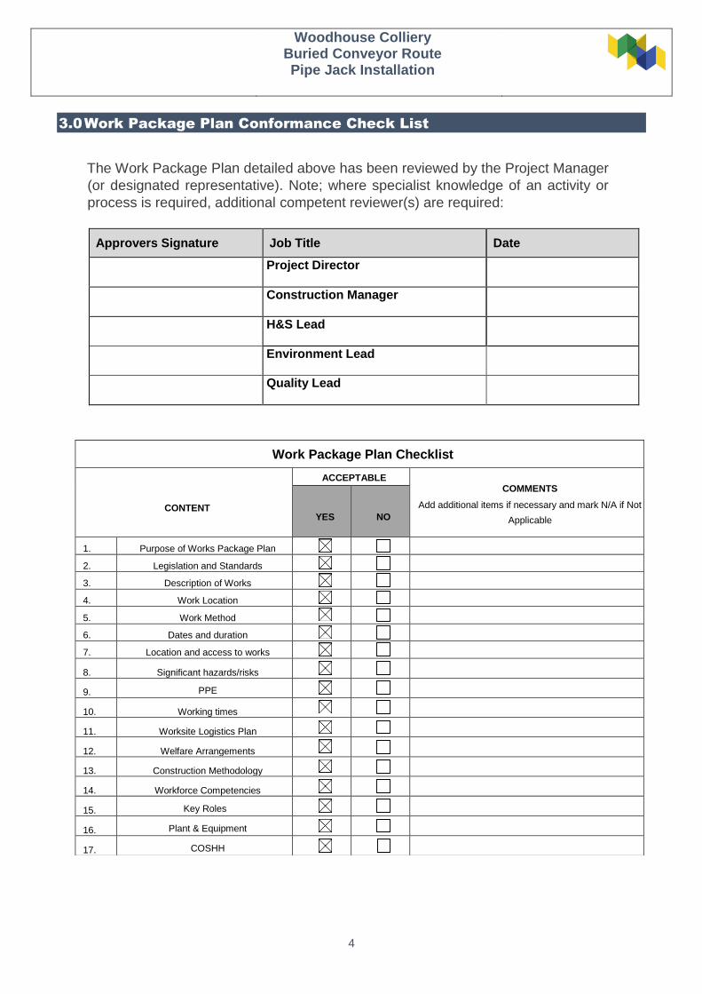
3.0 Work Package Plan Conformance Check List
The Work Package Plan detailed above has been reviewed by the Project Manager
(or designated representative). Note; where specialist knowledge of an activity or
process is required, additional competent reviewer(s) are required:
Approvers Signature Job Title Date
Project Director
Construction Manager
H&S Lead
Environment Lead
Quality Lead
Work Package Plan Checklist
CONTENT
ACCEPTABLE COMMENTS
Add additional items if necessary and mark N/A if Not
Applicable
YES
NO
1. Purpose of Works Package Plan
2. Legislation and Standards
3. Description of Works
4. Work Location
5. Work Method
6. Dates and duration
7. Location and access to works
8. Significant hazards/risks
9. PPE
10. Working times
11. Worksite Logistics Plan
12. Welfare Arrangements
13. Construction Methodology
14. Workforce Competencies
15. Key Roles
16. Plant & Equipment
17. COSHH

Woodhouse Colliery
Buried Conveyor Route Pipe Jack Installation
5
4.0 Purpose of Works Package Plan (WPP)
This document has been produced to clearly describe how the construction phase operations will be carried
out using safe systems of work for the Woodhouse Colliery buried conveyor pipejacking permanent works.
These works shall be conducted at the Buried Conveyor worksite, part of the Woodhouse Colliery
Construction scope of works. This WPP will only cover the works for the pipe jacking and connection at
either end for the conveyor alignment.
5.0 Legislation & Standards
Health & Safety at Work Act 1974
The CDM Regulations 2015
BS EN 6164:2019 Health and safety in tunnelling in the construction industry: Code of Practice
BS EN 6172: Code of practice for the safe use of cranes Parts 1 & 2
BS EN 12390: testing hardened concrete parts 1 to 11
The British Tunnelling Society (BTS) specification for tunnelling 3rd edition
6.0 Description of Works
The Buried Conveyor Pipe Jacking Works (BCPJ) will consist of the following activities:
1) Mobilisation of tunnelling equipment (jacking rig, hydraulic connections)
2) Cutting-out sheet piles for tunnel eye for jacking shield
3) Jacking of open face shield and tunnelling works (pipe jacking, use of Brokk excavator)
4) Cutting-out sheet piles for reception seal
5) Grouting the pipeline on completion of tunnelling
6) De-mobilisation and completion of works

Woodhouse Colliery
Buried Conveyor Route Pipe Jack Installation
6
7.0 Work Location
Figure 1 – Woodhouse Buried Conveyor (WBC): Aerial view of site location
The Woodhouse Colliery buried conveyor is a 2.3km long conveyor, running within a buried structure, from the
main mine site, the former Marchon works site, downhill in a southeast direction to the railway siding to be
constructed adjacent to the existing Cumbrian Coast railway line, in the Pow Beck Valley, south of Whitehaven.
Part of the buried conveyor route passes beneath the Whitehaven to St Bees Road – the B5345 (designated as
Zone 1 in Figure 1) and then passes under a section of Bellhouse Wood & Bellhouse Gill (designated as Zone 2
in Figure 1).

Woodhouse Colliery
Buried Conveyor Route Pipe Jack Installation
7
Figure 2 shows the red-line planning boundary and the alignment of the buried conveyor relevant to Zone 1 and
Zone 2.
Figure 2 – Woodhouse Buried Conveyor red-line boundary and alignment
Woodhouse Colliery
Buried Conveyor Route Pipe Jack Installation
8
8.0 Work Method
8.1 Method Overview
The majority of the buried conveyor will be constructed using conventional civil engineering methods, via an
open cut technique over a specific section length, installation of the buried structure (concrete or other pre-
fabricated units) and then burial and making good the ground surface to original condition.
To reduce the impact of construction on the two zones identified, firstly the B5345 St Bees Road, and secondly
the section of Bellhouse Wood, it is proposed that a pipejacking ‘tunnelling’ technique will be used instead of the
cut and cover open trench technique.
The zone 1 tunnel length is anticipated to be a maximum of 80m, at a minimum depth of 2m below surface to
the top of the tunnel lining. The tunnel external invert depth will be at least 5.2m, with the concrete pipes being
2.5m ID and 3.0m outside diameter (OD). There will be no requirement to close the road during the
construction works – live 24/7 monitoring of the road will be implemented for the duration of the pipejacking
works.
The zone 2 tunnel length is anticipated to be a maximum of 50m, at a minimum depth of 2m below surface to
the top of the tunnel lining. The tunnel external invert depth will be at least 5.2m, with the concrete pipes being
2.5m ID and 3.0m outside diameter (OD). There will be no requirement to disturb any of the existing woodland
for this section of the works.
Pipejacking is a very well proven trenchless technique, regularly used for smaller diameter (less than 5m
diameter) pipes/culverts over moderate distances and shallow depths. Many civil engineering contractors
specialise in the delivery of these trenchless techniques on a routine basis throughout the UK.
8.2 Pipejacking technique
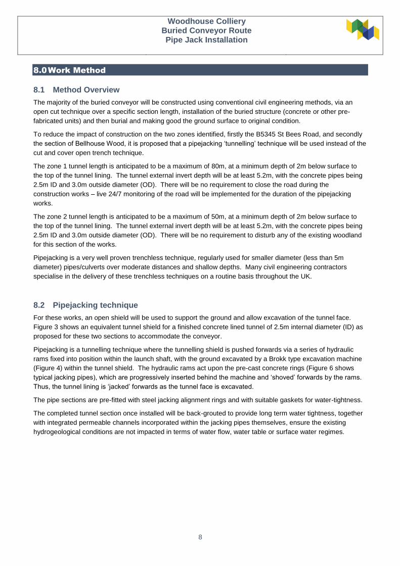
For these works, an open shield will be used to support the ground and allow excavation of the tunnel face.
Figure 3 shows an equivalent tunnel shield for a finished concrete lined tunnel of 2.5m internal diameter (ID) as
proposed for these two sections to accommodate the conveyor.
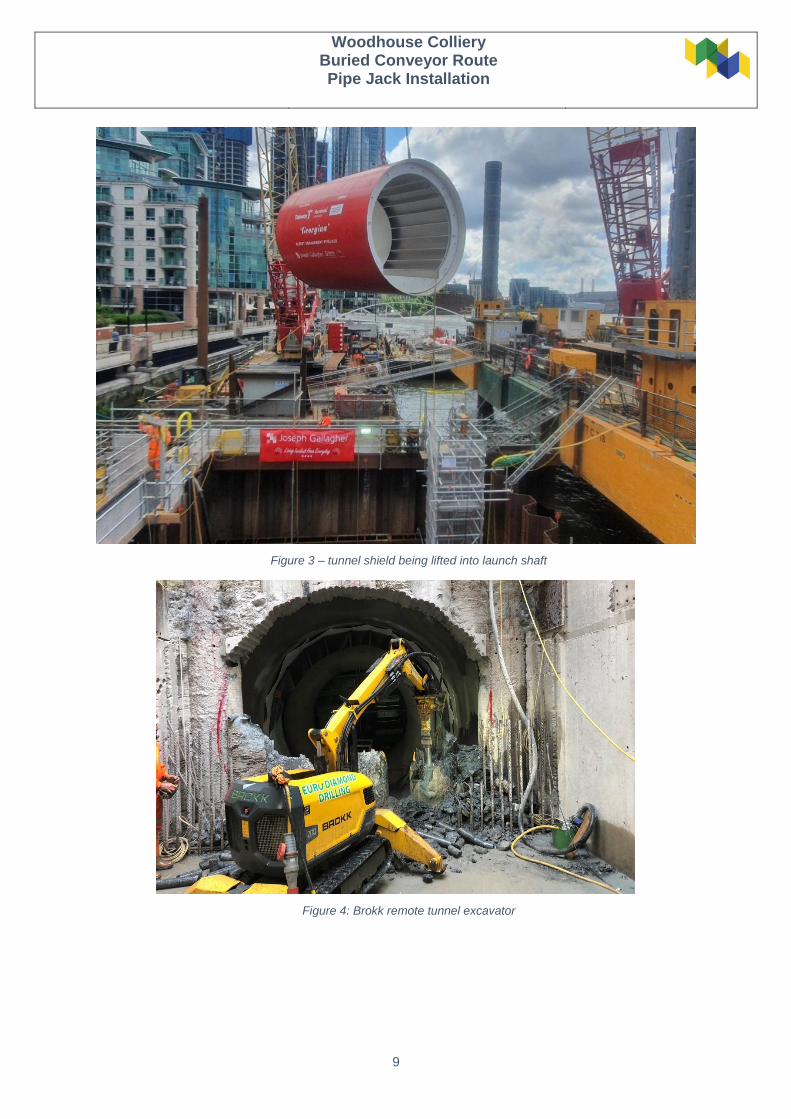
Pipejacking is a tunnelling technique where the tunnelling shield is pushed forwards via a series of hydraulic
rams fixed into position within the launch shaft, with the ground excavated by a Brokk type excavation machine
(Figure 4) within the tunnel shield. The hydraulic rams act upon the pre-cast concrete rings (Figure 6 shows
typical jacking pipes), which are progressively inserted behind the machine and ‘shoved’ forwards by the rams.
Thus, the tunnel lining is ‘jacked’ forwards as the tunnel face is excavated.
The pipe sections are pre-fitted with steel jacking alignment rings and with suitable gaskets for water-tightness.
The completed tunnel section once installed will be back-grouted to provide long term water tightness, together
with integrated permeable channels incorporated within the jacking pipes themselves, ensure the existing
hydrogeological conditions are not impacted in terms of water flow, water table or surface water regimes.
Woodhouse Colliery
Buried Conveyor Route Pipe Jack Installation
9
Figure 3 – tunnel shield being lifted into launch shaft
Figure 4: Brokk remote tunnel excavator
Woodhouse Colliery
Buried Conveyor Route Pipe Jack Installation
10
8.3 Temporary Shafts
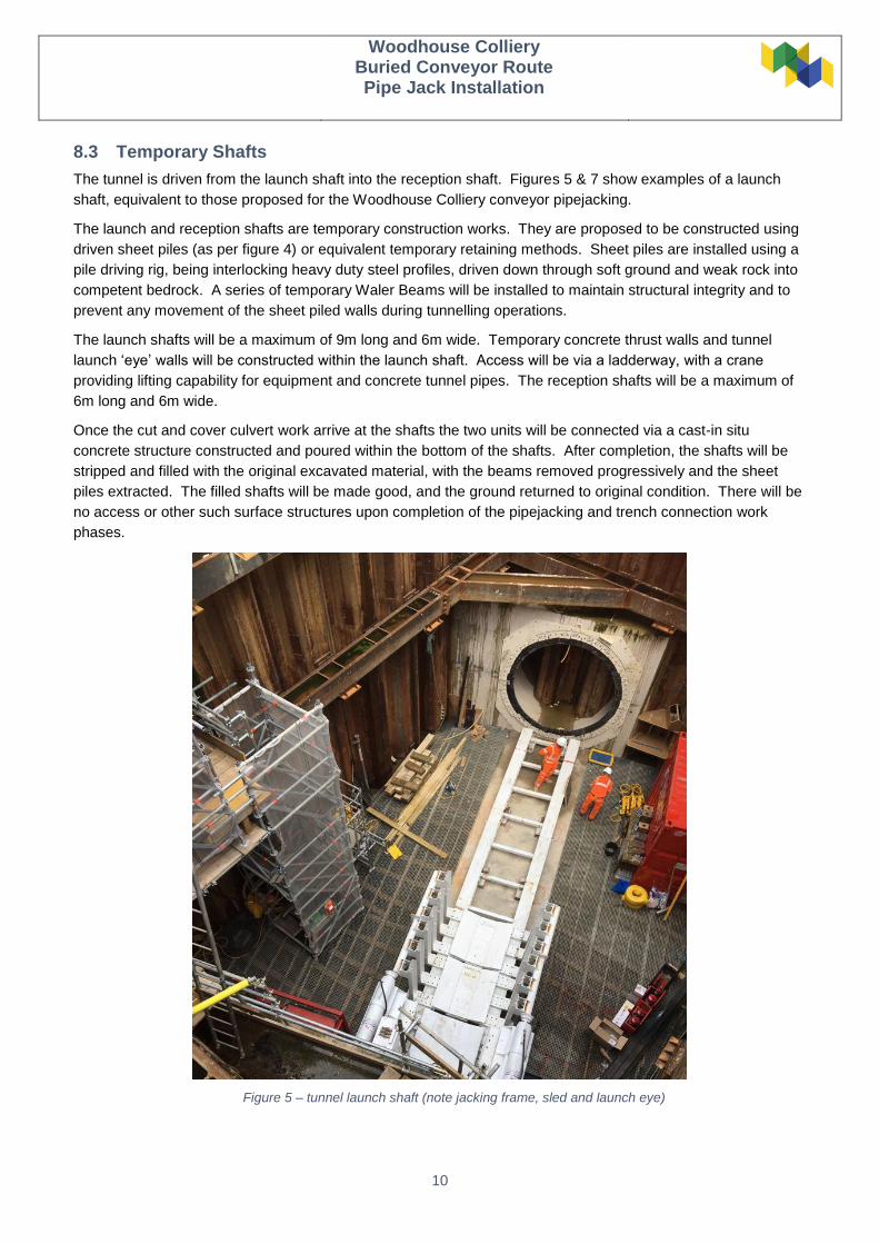
The tunnel is driven from the launch shaft into the reception shaft. Figures 5 & 7 show examples of a launch
shaft, equivalent to those proposed for the Woodhouse Colliery conveyor pipejacking.
The launch and reception shafts are temporary construction works. They are proposed to be constructed using
driven sheet piles (as per figure 4) or equivalent temporary retaining methods. Sheet piles are installed using a
pile driving rig, being interlocking heavy duty steel profiles, driven down through soft ground and weak rock into
competent bedrock. A series of temporary Waler Beams will be installed to maintain structural integrity and to
prevent any movement of the sheet piled walls during tunnelling operations.
The launch shafts will be a maximum of 9m long and 6m wide. Temporary concrete thrust walls and tunnel
launch ‘eye’ walls will be constructed within the launch shaft. Access will be via a ladderway, with a crane
providing lifting capability for equipment and concrete tunnel pipes. The reception shafts will be a maximum of
6m long and 6m wide.
Once the cut and cover culvert work arrive at the shafts the two units will be connected via a cast-in situ
concrete structure constructed and poured within the bottom of the shafts. After completion, the shafts will be
stripped and filled with the original excavated material, with the beams removed progressively and the sheet
piles extracted. The filled shafts will be made good, and the ground returned to original condition. There will be
no access or other such surface structures upon completion of the pipejacking and trench connection work
phases.
Figure 5 – tunnel launch shaft (note jacking frame, sled and launch eye)

Woodhouse Colliery
Buried Conveyor Route Pipe Jack Installation
11
Figure 6 – Pre-cast concrete jacking pipes
Figure 7 – tunnel shield lowered into launch shaft
Figure 8 - Example of finished tunnel
Woodhouse Colliery
Buried Conveyor Route Pipe Jack Installation
12
9.0 Dates and duration of work
Start date: TBC
End date: TBC
Duration of works for each zone: maximum 4 months
9.1 Location & Access to work
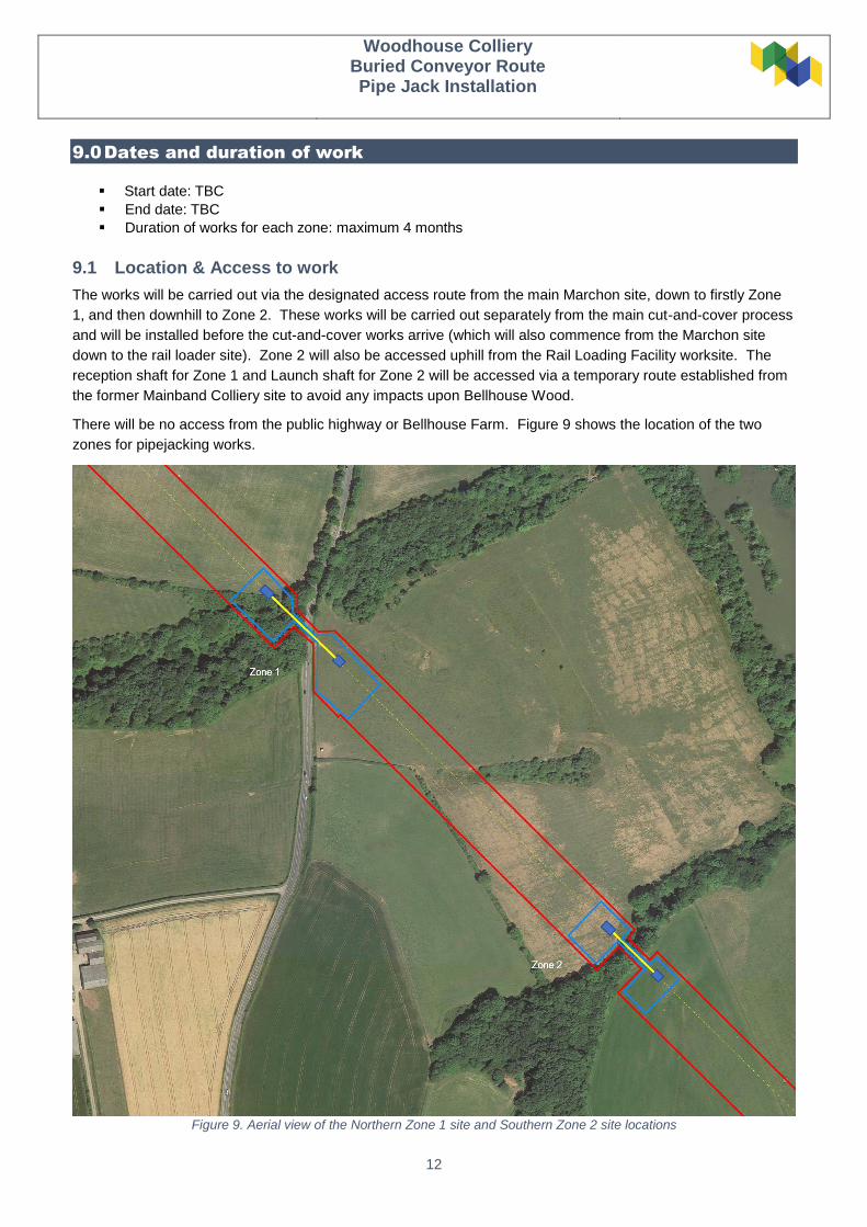
The works will be carried out via the designated access route from the main Marchon site, down to firstly Zone
1, and then downhill to Zone 2. These works will be carried out separately from the main cut-and-cover process
and will be installed before the cut-and-cover works arrive (which will also commence from the Marchon site
down to the rail loader site). Zone 2 will also be accessed uphill from the Rail Loading Facility worksite. The
reception shaft for Zone 1 and Launch shaft for Zone 2 will be accessed via a temporary route established from
the former Mainband Colliery site to avoid any impacts upon Bellhouse Wood.
There will be no access from the public highway or Bellhouse Farm. Figure 9 shows the location of the two
zones for pipejacking works.
Figure 9. Aerial view of the Northern Zone 1 site and Southern Zone 2 site locations

Woodhouse Colliery
Buried Conveyor Route Pipe Jack Installation
13
10.0 Personal Protective Equipment (PPE)
At all times operatives on site shall adhere to the mandatory site PPE requirements as out lined in the
Construction Phase plan. And these shall be a minimum of:
10.1 MANDATORY PPE
Orange high visibility trousers
Orange high visibility vest and or high visibility jacket
Orange high visibility t shirt
Hard hat
Task Specific gloves
Task Specific Eyewear
Steel toe cap footwear with midsole protection (not rigger boots)
Additional personal protective equipment may be required for specific works:
Hearing protection
Disposable coveralls
Flame retardant overalls, gloves, and face shield (for hot works cutting)
In addition, the following specific equipment will be required during the excavating of the face within the pipe
jack shield:
FFP3 Masks (face fit testing to be completed prior to commencing works and all operatives issued with
a mask suitable for the task)
Self-rescuer sets (MSA Savox, Drager Oxy 6000 or similar) will be kept within easy reach of working
area in accordance with BS 6164:2011. A storage box will be mounted with in the jacking shield, Ops
working in the shield will avail of the storage box whilst working. Sets to be carried between pit bottom
and shield through concrete pipes during access/Egress. Storage box to be installed in pit bottom for
the Permanent storage of MSA’s. Should operatives required to work within the concrete pipe section,
MSA’s to be hung on service brackets, next to work area.
For identification purposes, all Operatives will always wear orange high visibility clothing with hard hats
designated as follows.
Supervisors will wear Black (or Grey) hard hats.
Vehicle Marshalls will wear Red hard hats
Slinger signalers will wear Orange hard hats.
Apprentices, young workers, and visitors will wear yellow/teal hard hats.
All other site operatives will wear white hard hats
Task specific PPE that will be required for the specific task shall be highlighted in subsequent VTS
11.0 Working Times
Day Shift Working Hours: Monday – Friday 07:00 to 19:00
Saturday shifts may be necessary as works progress, these shall be primarily for maintenance and extending of
services and shall be agreed with FLO prior to works being arranged.
12.0 Welfare Arrangements
Full welfare is provided at the Marchon and Rail Loader sites.

Woodhouse Colliery
Buried Conveyor Route Pipe Jack Installation
14
13.0 Construction Methodology
13.1 General Works
Prior to works commencing all operatives will attend the WCM suite of inductions and be certified to work on
the conveyor route site. The contents of the relevant activity plan, associated risk assessment and lift plans
will be briefed to the site team by the supervisor in charge. Site specific tunnel induction will be carried out
for everyone working above ground and below ground.
Prior to lifting operations, the lift supervisor will inspect all certification relating to the crane and personnel to
ensure that they are all valid.
All plant movements to be controlled by a banksman.
Interfaces with other works in the designated areas for certain activities will be discussed and
agreed during daily morning co-ordination briefings. Areas to be clearly marked out on site.
HOLD POINT – Permit to enter must in place prior to access into the launch and reception pits
HOLD POINT – To lifting operations to take place with approved lift plan, and lift supervisor in
attendance to site
13.2 Deliveries to Site:
All plant, tools and materials required for the works will be delivered to the Marchon site for transfer to the
working site zones. Contractors to provide packing lists and weights for the items to be brought to site. Site
works to be laid out to allow for sufficient access around the plant items etc.
Material Loading and unloading
All loading and unloading of plant and accessories will be carried out using a Crawler crane and lifts will be
conducted in accordance with the approved lift plan.
13.3 Site Set up:
The following site set-up works will be completed prior to the start of excavation/ tunnelling works. See
below for temporary pit bottom layout.
Unloading and storage of tunnelling equipment
Installation of ventilation system
Installing and checking all plant to the provided electrics
Woodhouse Colliery
Buried Conveyor Route Pipe Jack Installation
15
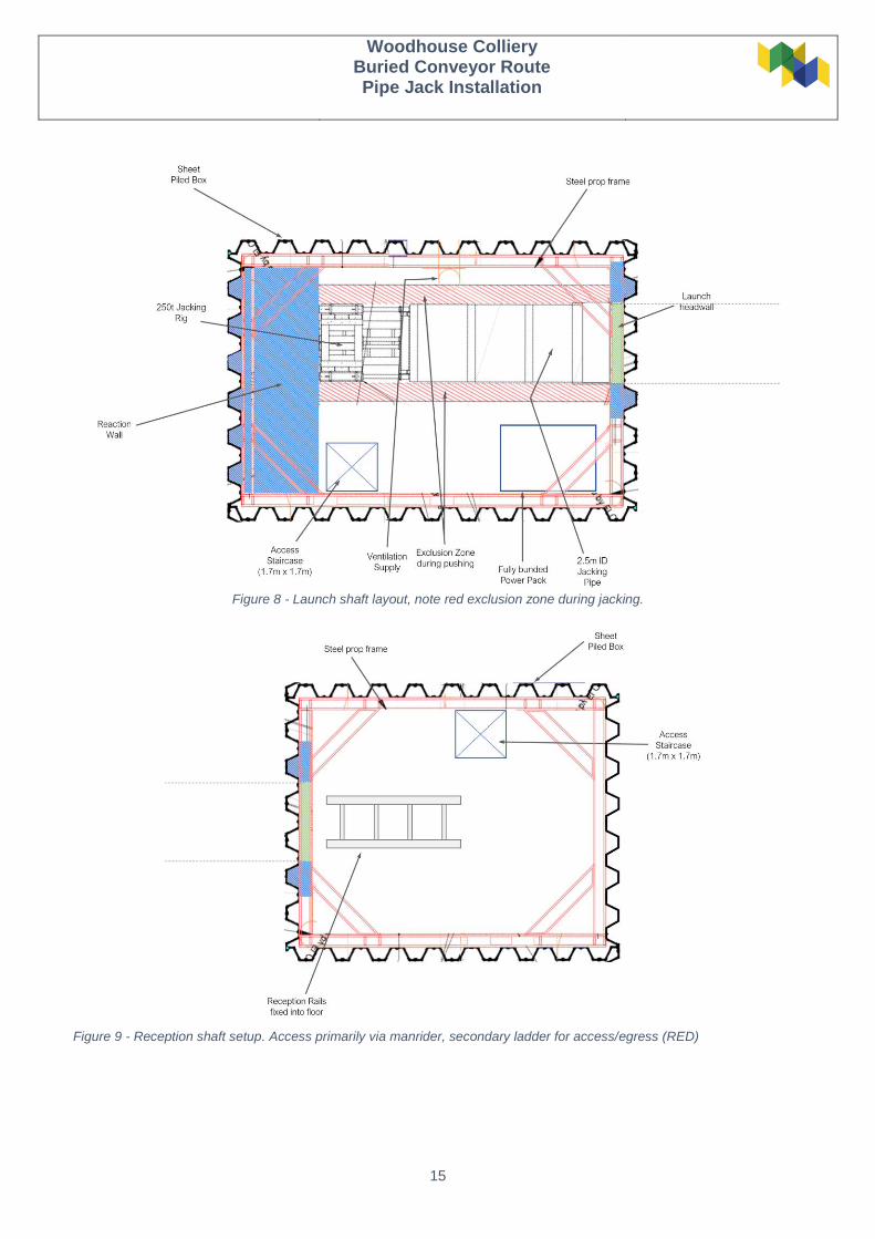
Figure 8 - Launch shaft layout, note red exclusion zone during jacking.
Figure 9 - Reception shaft setup. Access primarily via manrider, secondary ladder for access/egress (RED)
Woodhouse Colliery
Buried Conveyor Route Pipe Jack Installation
16
13.4 General Procedures:
13.4.1 Launch Pit Entry
Set up and Prior to tunnelling works
Access to the launch pit will be restricted during equipment installation – access by
consent from Pit Boss only.
13.4.2 Culvert Drive Entry/Access
All access to the pipe jack to be at the discretion of the Lead miner.
Requirements & control for entry to the pipeline & shield are:
o MSA’s
o Gas monitoring
o Extraction Ventilation
o Restricted to 3no people within the shield
o Only key personnel to be in pipejack whilst operational, electrician’s conveyor
men etc.
o All operatives accessing the tunnel to have specific tunnel training
o A full exclusion zone around the front face for which no access shall be
Permitted in front of the shield
Personnel gas detectors shall be carried to the tunnel face.
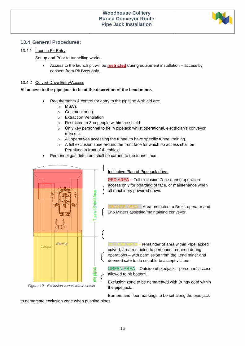
Indicative Plan of Pipe jack drive.
RED AREA – Full exclusion Zone during operation
access only for boarding of face, or maintenance when
all machinery powered down.
ORANGE AREA – Area restricted to Brokk operator and
2no Miners assisting/maintaining conveyor.
YELLOW AREA – remainder of area within Pipe jacked
culvert, area restricted to personnel required during
operations – with permission from the Lead miner and
deemed safe to do so, able to accept visitors.
GREEN AREA – Outside of pipejack – personnel access
allowed to pit bottom.
Exclusion zone to be demarcated with Bungy cord within
the pipe jack.
Barriers and floor markings to be set along the pipe jack
to demarcate exclusion zone when pushing pipes.
Figure 10 - Exclusion zones within shield
Woodhouse Colliery
Buried Conveyor Route Pipe Jack Installation
17
13.4.3 Hot Works:
Hot works must be carried out in accordance with the Hot Works Procedure
Hot works permit must be authorized by an appointed signatory prior to start of works
No acetylene allowed on the project.
13.4.4 Lifting operations:
All lifting operations will be carried out under an approved Lift Plan.
Hold point – Lifting above people and walking under suspended loads is NOT allowed under any
circumstances.
The Crawler cranes controlled by trained and competent operators, will be used for all the lifting
operations within the launch pit.
All slinging is to be carried out by a trained and competent slinger in accordance with arrangement on
the lift plan. The slinger/signaler must visually inspect each lifting accessories daily prior to use.
Crane supervisor must ensure that all the lifting operations are carried out in accordance with the lift
plan and that only trained and competent personnel direct lifting operations. Crane supervisor must
always be in attendance during lifting activities.
The pit bottom and top slinger/signalers (S/S) will control between each other the load movement and
clearance, instructing crane driver via radio signals.
Communication between crane driver and S/S must always be maintained with radios and when
interrupted all lifting operations should be suspended.
During lifting operations going into/out of the launch shaft, a whistle/alarm will be used by the slinger
to warn that lifting operations are ongoing.
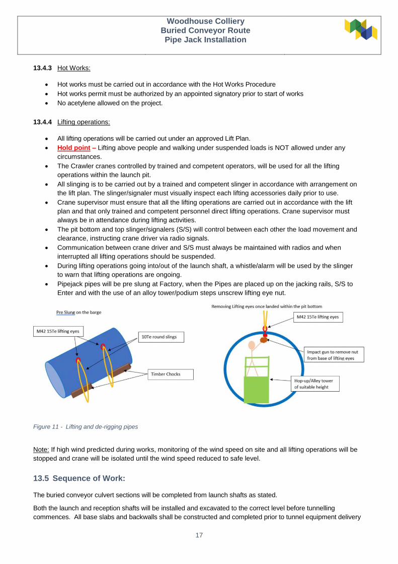
Pipejack pipes will be pre slung at Factory, when the Pipes are placed up on the jacking rails, S/S to
Enter and with the use of an alloy tower/podium steps unscrew lifting eye nut.
Note: If high wind predicted during works, monitoring of the wind speed on site and all lifting operations will be
stopped and crane will be isolated until the wind speed reduced to safe level.
13.5 Sequence of Work:
The buried conveyor culvert sections will be completed from launch shafts as stated.
Both the launch and reception shafts will be installed and excavated to the correct level before tunnelling
commences. All base slabs and backwalls shall be constructed and completed prior to tunnel equipment delivery
Figure 11 - Lifting and de-rigging pipes
Woodhouse Colliery
Buried Conveyor Route Pipe Jack Installation
18
to the project. RC headwalls will have been constructed with a void left for the tunnel annulus, ready for the sheet
piles to be cut.
The following steps detail the sequence steps of works for the tunnelling due to be completed:
13.5.1 Pipe Preparation
Final pipe preparation will be undertaken prior to installation. The preparation of the pipes will be undertaken off site at WCM’s holding yard at Lillyhall. WCM will install the Primary and Secondary Neoprene Gaskets, and the MDF packers for jacking. Installation of the Gaskets will be as per the manufacturer (e.g. Stanton Bonna) installation guide, with an outline as below:
The MDF packers will be installed on the leading and trailing edge of each pipe. The internal edge of
the pipe will be used as a guide to install the packers, 45mm from the internal edge;
Apollo glue will be used for gluing packers to the concrete;
When the packer glue has cured sufficiently such that the packers cannot be accidentally knocked off,
the Secondary gaskets will then be glued to the face;
The inside edge is used to guide the internal secondary gasket, keeping 15mm from the internal edge;
The external gasket will be guided from the external edge on the Leading edge of the pipes and the
collar on the trailing edge of the pipes;
Working from the top, an approx. 1m section of the gasket will have glue applied, the gasket will then be
held in place by the ops until the glue has cured, then moving down from the top glue will be
progressively applied and the gasket held in place until cured in sections until the full gasket has been
fitted. This will be repeated for each of the 4 secondary gaskets which are applied to each of the pipes.
(Pipe no 1 will not have leading edge secondary gaskets);
The primary gasket will be installed on the leading edge of each pipe, (including first pipe), as per the
installation guide; the gasket will be looped over the front of the pipe and set into the back step on the
spigot, checking the gasket is correctly orientated;
Two operatives stretch the gasket over the spigot. A third operative to feed the gasket over the bottom
of the spigot – then a final check to ensure the gasket is sitting against the backstop, and
Overall inspection of the installation condition, making sure all gaskets are clean and free from dirt and
contaminants.
13.5.2 Unloading and storage of tunnelling equipment
The works shall begin by unloading equipment at site. The unloading and storage shall generally follow the
process below:
Crane Supervisor is to be briefed on the lifting plan
All lifting equipment is to be checked prior to use
Sequence of lifting plant to be agreed and space made for plant to be located
Lifting plan ALWAYS to be adhered to during the lift
Exclusion zone shall be set up around the slew radius of the crane and an audible alarm to be used when
lifting
Plant to be landed by the slinger/ signaler into the agreed position
Woodhouse Colliery
Buried Conveyor Route Pipe Jack Installation
19
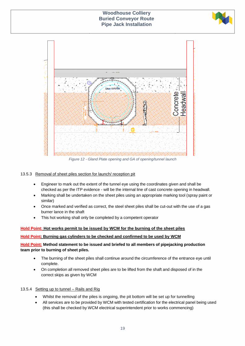
Figure 12 - Gland Plate opening and GA of opening/tunnel launch
13.5.3 Removal of sheet piles section for launch/ reception pit
Engineer to mark out the extent of the tunnel eye using the coordinates given and shall be
checked as per the ITP evidence - will be the internal line of cast concrete opening in headwall.
Marking shall be undertaken on the sheet piles using an appropriate marking tool (spray paint or
similar)
Once marked and verified as correct, the steel sheet piles shall be cut-out with the use of a gas
burner lance in the shaft
This hot working shall only be completed by a competent operator
Hold Point: Hot works permit to be issued by WCM for the burning of the sheet piles
Hold Point: Burning gas cylinders to be checked and confirmed to be used by WCM
Hold Point: Method statement to be issued and briefed to all members of pipejacking production
team prior to burning of sheet piles.
The burning of the sheet piles shall continue around the circumference of the entrance eye until
complete.
On completion all removed sheet piles are to be lifted from the shaft and disposed of in the
correct skips as given by WCM
13.5.4 Setting up to tunnel – Rails and Rig
Whilst the removal of the piles is ongoing, the pit bottom will be set up for tunnelling
All services are to be provided by WCM with tested certification for the electrical panel being used
(this shall be checked by WCM electrical superintendent prior to works commencing)

Woodhouse Colliery
Buried Conveyor Route Pipe Jack Installation
20
Engineer shall mark up the drive line of the tunnel from the coordinates given within the approved
drawings and mark on the shaft walls. The concrete slab level shall be confirmed to allow packers to
be placed prior to landing the jacking rig in the launch shaft
Hold Point: approved lifting plan to be in place and method of working agreed with crane prior to
works commencing in shaft
Jacking rig to be lifted following the approved lifting plan. A clear exclusion zone shall be in place
around the lifting slew and no persons to be allowed into this area
Jacking rig shall be lifted into the shaft and aligned to the 2 points given by the engineer, operatives
shall at no point be underneath the load
Rig landed atop rails and chains removed
Position for line and level shall be checked by the engineer using the total station and
confirmed as on the correct grade & position.
If the rig requires alignment, operatives shall use pinch bars to move on the shims it was landed
on.
13.5.5 Setting up to tunnel – Rig and power pack
Power pack to be placed in pit bottom and connected between the controls and the Jacking rig.
Hydraulic connections shall be set from the powerpack which was landed during the initial set
up works, this shall follow the micro-tunnelling procedure and the manufacturers guidance for
the power pack
Hydraulic connectors from the power pack shall be connected into the jacking rig and checked
for leaks/ damage
Pipejacking operator shall check that all jacks are working, and the emergency stop is in
working order prior to signing off as good to use
When sheet pile removal is complete, the shield will be pushed to the face ready for tunnelling
The conveyor belt will then be assembled within the pipejack from the shield back to the pit bottom
13.5.6 Setting up for tunnelling – Gland plate
The entry gland plate will be assembled on the base slab in the shaft bottom, consisting of all
components including the rubber seal
Guide bolts will be drilled into the headwall and threaded bar resin fixed to the headway. These
will be set out by the engineer
Assembled plate will be lifted vertical with the crane and guided onto to the headwall when the
guide bars have fully set
Subsequent bars will then be drilled through the gland plate as required
Bars will be resin fixed through the gland plate, when the resin has set the crane will be lowered,
and chains detached
After the resin has set the gland seal bolts will be tightened home to create a seal between the
plate and headwall.
13.5.7 Jacking of open face shield and tunnelling works (Pipe Jacking, use of Brokk)
Hold Point: Method statement to be issued and briefed to all members of the pipejacking production
team prior to commencing tunnelling works.
Operatives to power up Brokk using the electrical supply and check workings with the competent
operator, and pre use inspections to be undertaken on all plant prior to work commencing
Woodhouse Colliery
Buried Conveyor Route Pipe Jack Installation
21
The face will be progressively broken from the top down to accept the jacking shield accounting
for the angle of the hood until shield is fully encased in the face
Jacking shield will be pushed until there is clearance for additional pipe sections
Jacking will continue until there is a clearance of 2.5 meters from the back of the last jacking
pipe to the retracted jacks, to allow the next pipe to be inserted and attached
All jacking pipes shall be checked prior to being lifted into the launch shaft to ensure the packers
& gaskets are still correctly installed and no pipe defects are present
A pipe check sheet to be completed for all pipes being used within the pipe jack and kept on file
and counter signed by WCM, pipes to be continuously assessed
Brokk shall begin breaking in the face and loading the spoil on the conveyor belt to allow for
muck-away out the launch shaft
Operator shall be within the pipejack during the works and wearing PPE as necessary (this shall
include: all 5 items of PPE as specified by WCM and an additional dust mask and ear defenders
to be worn during these works
Note: Restriction zone to be maintained around the working pipe jack and no unauthorized
access into the pipe during the tunnelling works
Note: Dampening down to be completed during the works to reduce any excess dust
Once enough material has been cleared for a stroke then the lead miner will communicate to pit
bottom to shove the shield forward. The Operator/Lead miner will ensure that there is sufficient
overbreak around the shield to avoid any contact with the ground in the crown
Note: During jacking operation there will be an exclusion zone around the jacking rig while
hydraulic pressure is active
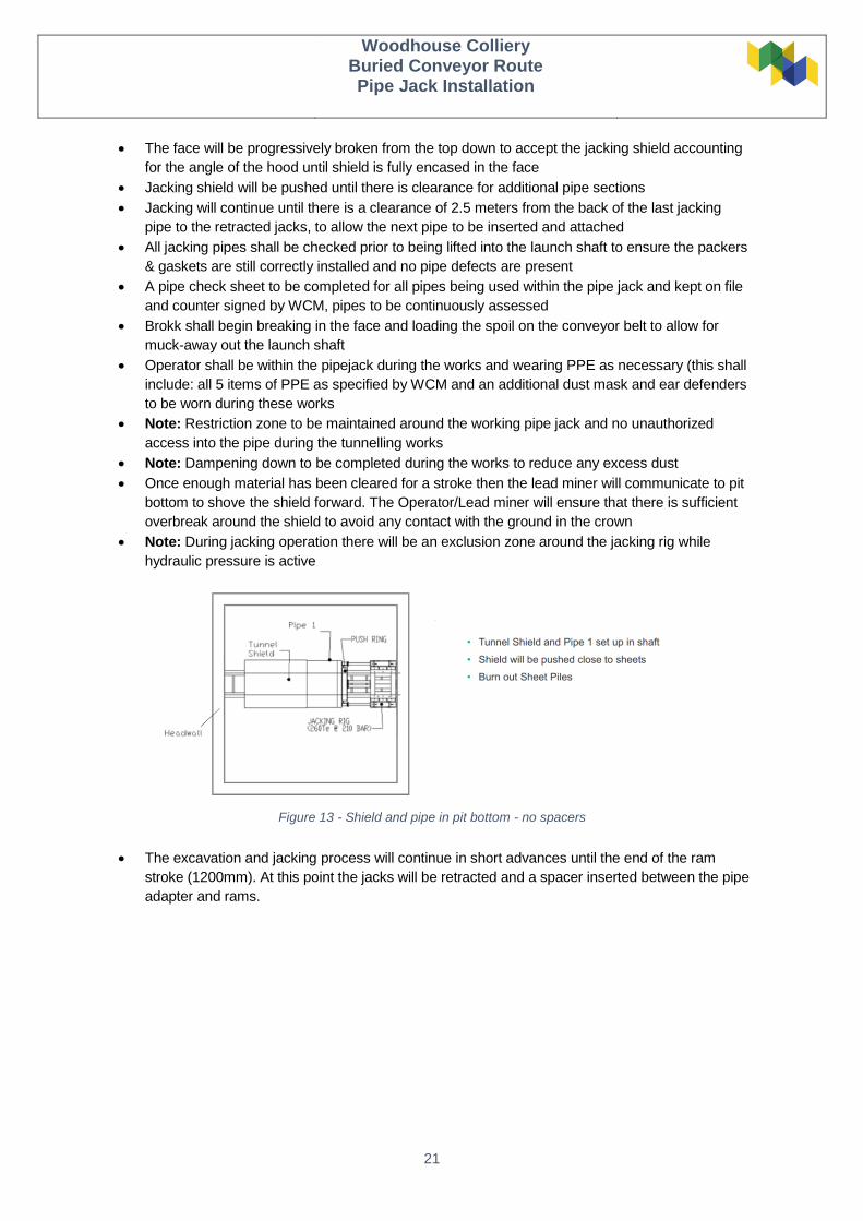
Figure 13 - Shield and pipe in pit bottom - no spacers
The excavation and jacking process will continue in short advances until the end of the ram
stroke (1200mm). At this point the jacks will be retracted and a spacer inserted between the pipe
adapter and rams.

Woodhouse Colliery
Buried Conveyor Route Pipe Jack Installation
22
Figure 14 - Shield, pipe and 1 jacking spacer (1.2m)
Excavation and jacking arrangement will repeat in small increments until the end of the stroke
(1200mm). Another 1200mm spacer will be installed between spacer 1 and the jacks.
The process will be repeated. At the end of the shove the 2no 1200mm spacers will be removed
and replaced with a 2500mm spacer.
Figure 15 - Shield, pipe and extended for 2.4m spacer
Once there is 6.2m clearance in the shaft (3no spacers and stroke of rams) then the jacks will be
retracted, and spacers removed.
2no pipes will be lowered into the pit bottoms individually and set upon the Jacking rails.
HOLD POINT – when pipes are placed upon the jacking rails, they are to be inspected for any
faults/damage prior to pushing home the joints and continuing jacking.
When the pipes have been inspected and passed, the collars are to be lubed and the pressure to be applied to
jacks and pipe joints pushed home, at which point jacking can recommence
Note: When lifting operations are undertaken within the shaft all pit bottom op’s will be within the pipe or
under the pit bottom refuge
Engineer shall check laser in the back of the jacking rig, for the duration of the jacking process to maintain the
correct fall on each pipe
The works shall continue throughout, and line and level shall be checked and documented on the
pipejacking check sheet during tunnelling
Jacking pressures and ground uncovered shall be documented also on the pipe jacking progress sheet
and issued for evidence.
Woodhouse Colliery
Buried Conveyor Route Pipe Jack Installation
23
The operator shall maintain a pressure on the jacks to ensure equal pushing. This shall continue to be
monitored throughout the pushing of the pipe
Tunnel spoil shall be removed into the pit bottom via the conveyor and removed from the shaft via a
muck skip and lifted in line with the approved lifting plan
The conveyor will discharge directly into the muck away skip, skip to fit beneath conveyor discharge.
Spoil to be removed to the allocated area given by WCM and removed from site following the Waste
removal plan
Note: Throughout the drive TK60 lubricant shall be pumped through the grout holes Left and Right
closest to the launch shaft within the product pipe. Only enough lubricant will be pumped into the
annulus to coat the invert due to the 45mm overcut around the pipes. Fully filling the annulus will cause
the face to be inundated with lubricant should there be an over break when excavating the face with the
Brokk.
Grout guns shall be screwed into the grout sockets and placed using the pneumatic grout pan
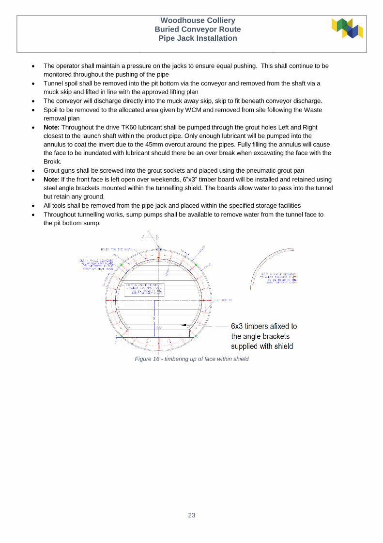
Note: If the front face is left open over weekends, 6”x3” timber board will be installed and retained using
steel angle brackets mounted within the tunnelling shield. The boards allow water to pass into the tunnel
but retain any ground.
All tools shall be removed from the pipe jack and placed within the specified storage facilities
Throughout tunnelling works, sump pumps shall be available to remove water from the tunnel face to
the pit bottom sump.
Figure 16 - timbering up of face within shield
Woodhouse Colliery
Buried Conveyor Route Pipe Jack Installation
24
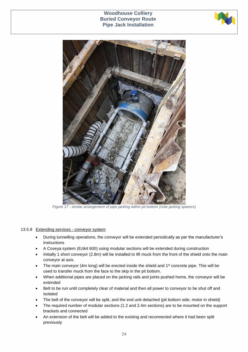
Figure 17 - similar arrangement of pipe jacking within pit bottom (note jacking spacers)
13.5.8 Extending services - conveyor system
During tunnelling operations, the conveyor will be extended periodically as per the manufacturer’s
instructions
A Coveya system (Ezikit 600) using modular sections will be extended during construction
Initially 1 short conveyor (2.8m) will be installed to lift muck from the front of the shield onto the main
conveyor at axis.
The main conveyor (4m long) will be erected inside the shield and 1st concrete pipe. This will be
used to transfer muck from the face to the skip in the pit bottom.
When additional pipes are placed on the jacking rails and joints pushed home, the conveyor will be
extended
Belt to be run until completely clear of material and then all power to conveyor to be shut off and
isolated
The belt of the conveyor will be split, and the end unit detached (pit bottom side, motor in shield)
The required number of modular sections (1.2 and 2.4m sections) are to be mounted on the support
brackets and connected
An extension of the belt will be added to the existing and reconnected where it had been split
previously
Woodhouse Colliery
Buried Conveyor Route Pipe Jack Installation
25
Belt to be powered up and test run before recommencing excavation and loading
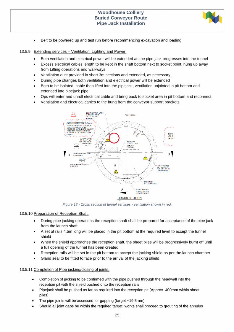
13.5.9 Extending services – Ventilation, Lighting and Power.
Both ventilation and electrical power will be extended as the pipe jack progresses into the tunnel
Excess electrical cables length to be kept in the shaft bottom next to socket point, hung up away
from Lifting operations and walkways
Ventilation duct provided in short 3m sections and extended, as necessary.
During pipe changes both ventilation and electrical power will be extended
Both to be isolated, cable then lifted into the pipejack, ventilation unjointed in pit bottom and
extended into pipejack pipe
Ops will enter and unroll electrical cable and bring back to socket area in pit bottom and reconnect
Ventilation and electrical cables to the hung from the conveyor support brackets
Figure 18 - Cross section of tunnel services - ventilation shown in red.
13.5.10 Preparation of Reception Shaft.
During pipe jacking operations the reception shaft shall be prepared for acceptance of the pipe jack
from the launch shaft
A set of rails 4.5m long will be placed in the pit bottom at the required level to accept the tunnel
shield
When the shield approaches the reception shaft, the sheet piles will be progressively burnt off until
a full opening of the tunnel has been created
Reception rails will be set in the pit bottom to accept the jacking shield as per the launch chamber
Gland seal to be fitted to face prior to the arrival of the jacking shield
13.5.11 Completion of Pipe jacking/closing of joints.
Completion of jacking to be confirmed with the pipe pushed through the headwall into the
reception pit with the shield pushed onto the reception rails
Pipejack shall be pushed as far as required into the reception pit (Approx. 400mm within sheet
piles)
The pipe joints will be assessed for gapping (target ~19.5mm)
Should all joint gaps be within the required target, works shall proceed to grouting of the annulus
Woodhouse Colliery
Buried Conveyor Route Pipe Jack Installation
26
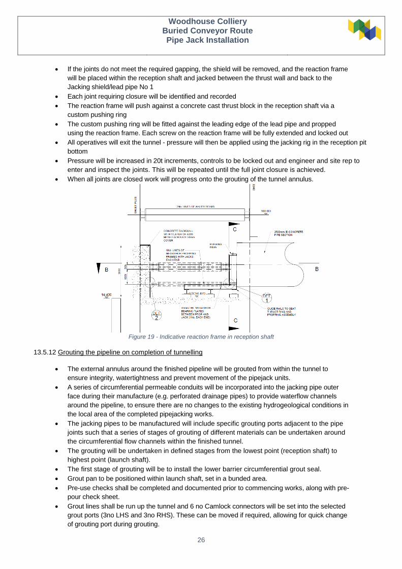
If the joints do not meet the required gapping, the shield will be removed, and the reaction frame
will be placed within the reception shaft and jacked between the thrust wall and back to the
Jacking shield/lead pipe No 1
Each joint requiring closure will be identified and recorded
The reaction frame will push against a concrete cast thrust block in the reception shaft via a
custom pushing ring
The custom pushing ring will be fitted against the leading edge of the lead pipe and propped
using the reaction frame. Each screw on the reaction frame will be fully extended and locked out
All operatives will exit the tunnel - pressure will then be applied using the jacking rig in the reception pit
bottom
Pressure will be increased in 20t increments, controls to be locked out and engineer and site rep to
enter and inspect the joints. This will be repeated until the full joint closure is achieved.
When all joints are closed work will progress onto the grouting of the tunnel annulus.
Figure 19 - Indicative reaction frame in reception shaft
13.5.12 Grouting the pipeline on completion of tunnelling
The external annulus around the finished pipeline will be grouted from within the tunnel to
ensure integrity, watertightness and prevent movement of the pipejack units.
A series of circumferential permeable conduits will be incorporated into the jacking pipe outer
face during their manufacture (e.g. perforated drainage pipes) to provide waterflow channels
around the pipeline, to ensure there are no changes to the existing hydrogeological conditions in
the local area of the completed pipejacking works.
The jacking pipes to be manufactured will include specific grouting ports adjacent to the pipe
joints such that a series of stages of grouting of different materials can be undertaken around
the circumferential flow channels within the finished tunnel.
The grouting will be undertaken in defined stages from the lowest point (reception shaft) to
highest point (launch shaft).
The first stage of grouting will be to install the lower barrier circumferential grout seal.
Grout pan to be positioned within launch shaft, set in a bunded area.
Pre-use checks shall be completed and documented prior to commencing works, along with pre-
pour check sheet.
Grout lines shall be run up the tunnel and 6 no Camlock connectors will be set into the selected
grout ports (3no LHS and 3no RHS). These can be moved if required, allowing for quick change
of grouting port during grouting.
Woodhouse Colliery
Buried Conveyor Route Pipe Jack Installation
27
Grout will be injected through these grout ports until it exits at the next upper ring of ports, with
bleed pipes inserted through non-return valves and opened until lubricant has been purged and
flowing grout is visible. Each port will then be closed progressively from the invert to crown as
grout flows from these open ports.
Once the grout has been given sufficient setting time, the next stage will be to pump via the
next set of ports a low viscosity, low slump and quick setting grout into the next section of
tunnel, using the same approach as for the first cement grout section, either side of the pre-
installed drainage channel. This grout (potentially resin or similar) will act as a stop-end to
prevent cement grout leaking into or around the drainage channels.
This process will continue along the full length of the pipejack, in alternative sections of
conventional grout and then low viscosity grout, to provide the protection to both the tunnel and
the permeable drainage conduits.
Grouting from the reception headwall will continue until grout is visible coming from the launch
headwall (low to high end of tunnel).
Grout cubes shall be taken from the first batch of each day of grouting by the engineer prior to
commencement of works; these will verify the strength gain for releasing jacks.
Grouting to take place following the detailed procedure and correct PPE to be worn during the
grouting works.
All COSHH waste to be removed in the designated waste bins for COSHH waste (Grout bags
and used grout connectors).
Upon completion of grouting the annulus, grout holes within the tunnel to be made good, using
approved making good material (MasterEmaco 5400).
13.5.13 Significant Tasks.
Dealing with groundwater
The pipe jacking route lies beneath two small ephemeral watercourses, which flow at times of
heavy/seasonal rainfall. During these times, ground water may also be present. Temporary ground
water diversion measures (if required) will be implemented prior to commencement of tunnelling works.
Such measures include an option for directional drilling to provide conduits for groundwater to ensure
that flows are not affected once the conveyor is installed.
Back up sump pumps to be available should there be excess water building up in the tunnel face during
excavation.
Water will be pumped from the tunnel shield to sump located in pit bottom.
Maintaining directional control
A laser will be set up in pit bottom before the Pipe jacking commences, this will be at the same angle
and bearing as the Centerline of the tunnel drive, can be offset to a known point within the shield.
At the back of the shield there will be a loose ring between the shield and the Lead concrete pipe.
The loose ring will have pockets for placing of a small Enerpac to enable opening of the joint between
the Shield and lead ring.
This will allow for steering and adjustment of the direction of the jacking shield to correct any deviation
from line or level.

Woodhouse Colliery
Buried Conveyor Route Pipe Jack Installation
28
Rolling of shield
Shield will be provided with exposed ribs on the
internal faces.
These will be used for the storage of tools etc. when
required.
Should the shield begin to roll, iron weights will be
installed within the ribs.
The side that is rolling high will be loaded with
weights to counter the effect rolling.
Once righted, the weights to be removed.
Woodhouse Colliery
Buried Conveyor Route Pipe Jack Installation
29
14.0 Workforce Competencies
All operatives will hold relevant qualifications based on their specific task, including but not limited to:
full body harness training,
slinger/signaler,
CPCS,
CSCS,
AP,
NVQ,
SMSTS schemes.
15.0 Key Roles
Pit Boss/ Supervisor/ Foreman – overall site responsibility for tunnel works and workforce
Lead Miner(s) – responsible for immediate works area, maintenance of all exclusion zone and works
involved
Miners – Responsible for working in line with the method statement and instruction from Lead Miner
(CPCS)
Brokk Operator/ Plant Operator – (CPCS endorsement for the piece of plant)
Shift Engineer – Responsible for quality control of tunnel works, confirmation of line/ level, instructing
sequence of work and ensuring works are carried out as per the ITP and Method Statement. Ensuring
works are within the designed document and to the parameters detailed. Engineer to Hold 3rd level
qualification with minimum 1-year site engineering experience.
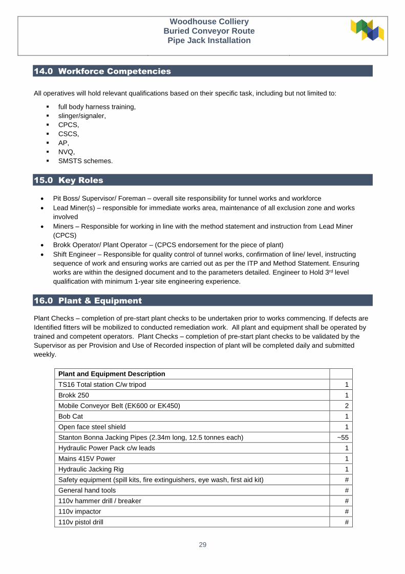
16.0 Plant & Equipment
Plant Checks – completion of pre-start plant checks to be undertaken prior to works commencing. If defects are
Identified fitters will be mobilized to conducted remediation work. All plant and equipment shall be operated by
trained and competent operators. Plant Checks – completion of pre-start plant checks to be validated by the
Supervisor as per Provision and Use of Recorded inspection of plant will be completed daily and submitted
weekly.
Plant and Equipment Description
TS16 Total station C/w tripod 1
Brokk 250 1
Mobile Conveyor Belt (EK600 or EK450) 2
Bob Cat 1
Open face steel shield 1
Stanton Bonna Jacking Pipes (2.34m long, 12.5 tonnes each) ~55
Hydraulic Power Pack c/w leads 1
Mains 415V Power 1
Hydraulic Jacking Rig 1
Safety equipment (spill kits, fire extinguishers, eye wash, first aid kit) #
General hand tools #
110v hammer drill / breaker #
110v impactor #
110v pistol drill #
Woodhouse Colliery
Buried Conveyor Route Pipe Jack Installation
30
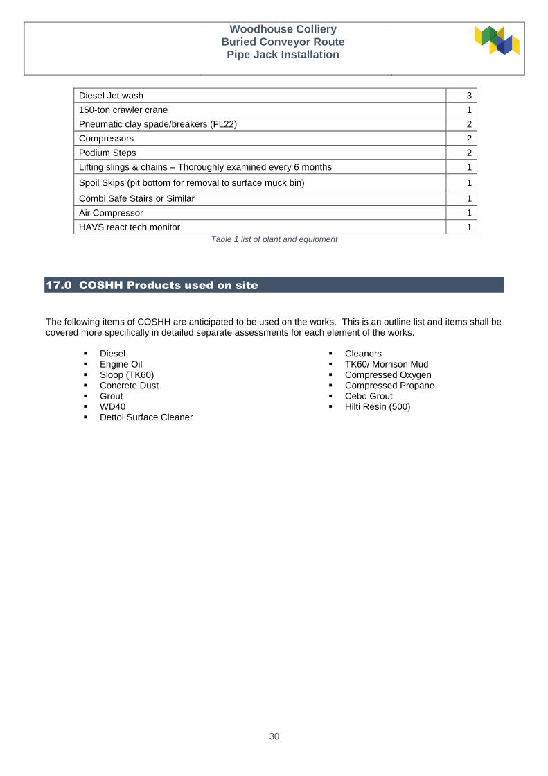
Diesel Jet wash 3
150-ton crawler crane 1
Pneumatic clay spade/breakers (FL22) 2
Compressors 2
Podium Steps 2
Lifting slings & chains – Thoroughly examined every 6 months 1
Spoil Skips (pit bottom for removal to surface muck bin) 1
Combi Safe Stairs or Similar 1
Air Compressor 1
HAVS react tech monitor 1
Table 1 list of plant and equipment
17.0 COSHH Products used on site
The following items of COSHH are anticipated to be used on the works. This is an outline list and items shall be covered more specifically in detailed separate assessments for each element of the works.
Diesel Engine Oil Sloop (TK60) Concrete Dust Grout WD40 Dettol Surface Cleaner
Cleaners TK60/ Morrison Mud Compressed Oxygen Compressed Propane Cebo Grout Hilti Resin (500)