Embed Size (px)
Citation preview
P/N 70000422B
Wizard 450/450L Digital Readout
Operations Manual
7
F
21
0
3
4 5 6
98
+- CL
WIZARD 450L
SET MMINCH INCR
ABS
ENT
RCL
ADV

iii
Warranty ANILAM warrants its products to be free from defects in material and workmanship for three (3) years from date of installation. At our option, we will repair or replace any defective product upon prepaid return to our factory. This warranty applies to all products when used in a normal industrial environment. Any unauthorized tampering, misuse, or neglect will make this warranty null and void. Under no circumstances will ANILAM, any affiliate, or related company assume any liability for loss of use or for any direct or consequential damages. The foregoing warranties are in lieu of all other warranties expressed or implied, including, but not limited to, the implied warranties of merchantability and fitness for a particular purpose. System Purchased From: ____________________________ Console Part Number:_______________________________ Console Serial Number: _____________________________ Date of Installation: _________________________________
Feature, Operation, and Technology WIZARD Digital Readouts provide the absolute latest in ease of operation, capability, and technology. As a result, ANILAM may alter and enhance operation, features, and capabilities without notice. © Copyright 2004 ACU-RITE Companies, Inc.

v
Contents Contents ................................................................................................................................. v Introducing the Wizard............................................................................................................1 The ANILAM Wizard 450/450L Keypad and Display Windows ....................................2 The ANILAM Wizard 450/450L Back Panel..................................................................3 First-Time User Checklist .......................................................................................................5 About This Manual..................................................................................................................7 Function Code List..................................................................................................................8 Beeper OFF/ON – F 21 ........................................................................................................11 Keyboard Entry Error ............................................................................................................12 Inch/Metric Conversion.........................................................................................................13 Decimal Degree to Degree-Minutes-Seconds Conversion...................................................14
Plus/Minus (±) Key................................................................................................................15 Absolute/Incremental (ABS/INCR) Key ................................................................................16 Presetting a Dimension ........................................................................................................17 Recalling a Preset Dimension ..............................................................................................18 Clearing a Preset Dimension................................................................................................19 Resetting an Axis to Zero .....................................................................................................20 Axis Reset Only – F 16.........................................................................................................21 Absolute Zero Set – F 01......................................................................................................23 Absolute Zero Set at Reference Mark – F 90.......................................................................24 EverTrackTM Mode – F 02.....................................................................................................25 Last Position Save/Recall – F 10/F 11 .................................................................................30 Adding/Subtracting Values ...................................................................................................31 Dividing an Axis Value by 2 ..................................................................................................32 Centering Key .......................................................................................................................33 Radius/Diameter per Axis – F 05..........................................................................................35 Setting a Correction Factor – F 03 .......................................................................................37 100-Point Axis Error Compensation – F 80/F 81..................................................................39 Measure the Axis ........................................................................................................39

vi
Contents (Continued) Selecting the Compensation Table, Entering an Axis Compensation ........................41 Key Functions for Compensation Table......................................................................44 Deleting a Compensation Value Table .......................................................................45 Axis Error Compensation ON/OFF .............................................................................46 Correction Factor OFF/ON – F 04 ........................................................................................47 Approaching Zero Indicator ..................................................................................................48 Approaching Zero – F 06......................................................................................................49 Approaching Zero Range – F 07 ..........................................................................................51 Approaching Zero Audio ON/OFF – F 08.............................................................................53 Connecting the Edge Sensor Probe.....................................................................................54 Edge Sensor Probe – F 09 ...................................................................................................55 Feedrate ON/OFF – F 26 .....................................................................................................57 Job Clock ON/OFF – F 34 ....................................................................................................58 Parameter Settings – F 20....................................................................................................60 Setting Up Encoder Parameters...........................................................................................60 Metric Linear Encoders.........................................................................................................62 Inch Linear Encoders (BT or JB Linear Encoders)...............................................................67 Rotary Encoders ...................................................................................................................68 Display Dim OFF/ON – F 22/ F 23 .......................................................................................72 Axis Designation – F 24........................................................................................................73 Select Language – F 99 .......................................................................................................74 Linear Encoder Error Detect OFF/ON – F 40/F 41...............................................................75 Diagnostics – F 45 ................................................................................................................76 Advanced (ADV) Functions Key ...........................................................................................78 Help Function..............................................................................................................78 Bolt-Hole Pattern Function (450 Only)........................................................................80 Partial Bolt-Hole Pattern .............................................................................................82 Full Bolt-Hole Pattern (450 Only)................................................................................86 Recalling Bolt-Hole Pattern Function (450 Only)........................................................90

vii
Contents (Continued) Linear-Hole/Frame-Hole Pattern Function (450 Only)................................................93 Recalling Linear-Hole/Frame-Hole Function (450 Only).............................................98 Taper Calculator Function (450L Only).....................................................................101 Datum Key (450 Only) ........................................................................................................103 Enter Datum..............................................................................................................103 Enter Datum (Alternate Method)...............................................................................106 Recall Datum ............................................................................................................108 Clear Datum – F 31...................................................................................................109 Tool Offset Key (450L Only) ...............................................................................................110 Enter Tool Offset.......................................................................................................110 Recall Tool Offset .....................................................................................................112 Modify Tool Offset – F 35 .........................................................................................113 Clear Tool Offset – F 32............................................................................................114 Axis Coupling (450L, 3-Axis Only) - F 18 ...........................................................................115 Output Connections (With I/O Option Only) .......................................................................116 Input Connections (With I/O Option Only) ..........................................................................117 Zero Output ON/OFF (With I/O Option Only) – F 33 .........................................................118 Approaching Zero Output Axis (With I/O Option Only) – F 14 ...........................................119 Zero Output Time Select (With I/O Option Only) – F 25.....................................................120 RS-232 Interface (With I/O Option Only) ............................................................................121 RS-232 Setup (With I/O Option Only) – F 27 .....................................................................122 RS-232 ON/OFF (With I/O Option Only) – F 28 .................................................................125 Printing Axis Values (With I/O Option Only) .......................................................................126 Remote Operation (With I/O Option Only)..........................................................................127 Relay 1/Relay 2 Setup (With I/O Option Only) – F 38/F 39................................................128 Output Test (With I/O Option Only) – F 42 .........................................................................131 Constant Surface Speed (CSS) Setup (450L With CSS and I/O Options).........................132 DAC Output Voltage Setup (450L With CSS and I/O Options) – F 96 ..............................133 DAC Output Voltage Offset Adjustment (450L With CSS and I/O Options) – F 97 ..........135

viii
Contents (Continued) DAC Output Voltage Test (450L With CSS and I/O Options) – F 98 ................................136 Constant Surface Speed (CSS)/Direct RPM Operation (450L With CSS and I/O Options)137 CSS/Direct RPM Input (450L With CSS and I/O Options) – F 48 .....................................138 DAC Output Voltage ON/OFF (450L With CSS and I/O Options) – F 50 ..........................142 Troubleshooting ..................................................................................................................143 Index-1..........................................................................................................................Index-1

1
Introducing the Wizard Thank you for purchasing the ANILAM Wizard 450/450L Digital Readout (DRO).
Review these pages carefully to learn how to properly operate your new DRO.
The new DRO offers many features and capabilities never before used in conventional DRO systems. Two models are available: the standard Wizard 450 DRO and the special lathe version Wizard 450L DRO, which includes turning features such as tool-length offsets and taper checking.
This manual was written with you, the operator, in mind. Please take the time to study it. A little well-spent time now will ensure many years of trouble-free operation. For additional information, please contact your local authorized ANILAM distributor, or call us directly:
ANILAM One Precision Way
Jamestown, New York, U.S.A., 14701 Phone: (716) 661-1700 FAX: (716) 661-1884
E-mail: [email protected] www.anilam.com

2
Introducing the Wizard (Continued)
The ANILAM Wizard 450/450L Keypad and Display Windows
NOTE: The Wizard 450 DRO is available in one-axis, two-axes, and three-axes models; the Wizard 450L DRO is available in two-axes and three-axes models. For simplicity, the procedures in this manual describe a three-axes model only.
ENTer Key
Axis Displays
Plus/Minus Key
ReCaLl Key
ADVanced Function Key
Numeric Keys
Message Window
Axis Keys
SET Key
Function Key
MM/INCH Key
ABSolute/INCRementalKey
Centering Key
Datum Key (450 Only)Tool Offset Key (450L Only)
ENT
RCL
7
MMINCHFSET
CL
21
0
3
4 5 6
98
ADV
WIZARD 450
+_
ABSINCR

3
Introducing the Wizard (Continued)
The ANILAM Wizard 450/450L Back Panel
GroundConnection
Cover Slot
ON/OFFSwitch
Power CordConnection
Edge SensorConnection
I/O OutputsConnection(I/O Option)
RS 232Connection(I/O Option)
EncoderConnections
I/O InputsConnection(I/O Option)
I
O

4
Introducing the Wizard (Continued)
Your Wizard’s display was designed to be easy to read:
ABS RST CF RI MM INCH
Axis Indicator
Indicates X1 or Z1
Coarse Resolution
Diameter Mode
Absolute Mode
Axis Reset Only
Correction Factor
Reference Indicator
MM or INCH Mode
Edge Sensor
Approaching ZeroIndicator

5
First-Time User Checklist Your new DRO has many preset values. Before you proceed, please review the following list to verify default settings. If you need to change any setting(s), refer to Parameter Settings – F 20.
Description of Setting Factory Setting Your Setting 450 DRO 450L DRO
1. Mill/Lathe Operation MILL LATHE
2. Linear Encoder Resolution Axis 1 5 µm Axis 2 5 µm
Axis 3 5 µm
3. Direction of Count Axis 1 + Axis 2 +
Axis 3 +
4. Position Tolerance Indicator Axis 1 Set to Zero Axis 2 Set to Zero Axis 3 Set to Zero
5. Audible Keyboard Tone ON
6. Display Resolution Axis 1 .0002 inches (.005mm)
Axis 2 .0002 inches (.005mm)
Axis 3 .0002 inches (.005mm)
7. Display Dimming 15 Minutes
8. Radius/Diameter Mode Axis 1 Radius Diameter
Axis 2 Radius Diameter Axis 3 Radius Diameter
6
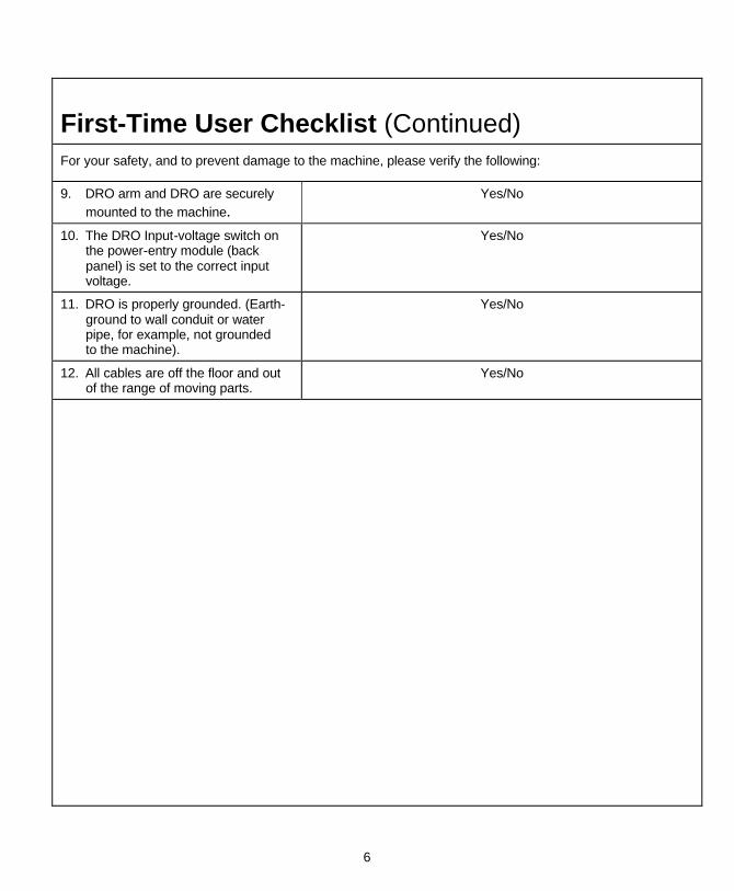
First-Time User Checklist (Continued) For your safety, and to prevent damage to the machine, please verify the following:
9. DRO arm and DRO are securely mounted to the machine.
Yes/No
10. The DRO Input-voltage switch on the power-entry module (back panel) is set to the correct input voltage.
Yes/No
11. DRO is properly grounded. (Earth-ground to wall conduit or water pipe, for example, not grounded to the machine).
Yes/No
12. All cables are off the floor and out of the range of moving parts.
Yes/No

7
About This Manual This manual contains limited text and enlarged graphics for easy use. Actual keystrokes are represented by graphics.
The format is as follows:
Function Heading
Function Description
Example with Keystrokes
Explanation of Procedures and Observations
NOTE: Indicates you must use caution.

8
Function Code List You can access most DRO features using function codes. Function codes are codes entered by pressing the Function key (F) and then pressing the two-digit code for the feature. The following table lists the function codes available with your DRO. The page number indicates where the function is described in this manual.
Code Description Page
F 01 Absolute Zero Set 23
F 02 EverTrackTM Mode 25
F 03 Setting a Correction Factor 37
F 04 Correction Factor OFF/ ON 47
F 05 Radius/Diameter per Axis 35
F 06 Approaching Zero 49
F 07 Approaching Zero Range 51
F 08 Approaching Zero Audio ON/OFF 53
F 09 Edge Sensor Probe 55
F 10 Last Position Save 30
F 11 Last Position Recall 30
F 14 Approaching Zero Output Axis Select (With I/O Option Only) 119
F 16 Axis Reset Only 21
F 18 Axis Coupling (450L, 3-Axis Only) 115
F 20 Parameter Settings 60
F 21 Beeper OFF/ ON 11
F 22 Display Dim OFF 72
F 23 Display Dim ON 72
F 24 Axis Designation 73

9
Function Code List (Continued) Code Description Page
F 25 Zero Output Time Select (With I/O Option Only) 120
F 26 Feedrate ON/OFF 57
F 27 RS-232 Setup (With I/O Option Only) 122
F 28 RS-232 ON/OFF (With I/O Option Only) 125
F 31 Clear Datum 109
F 32 Clear Tool Offset (450L Only) 114
F 33 Zero Output ON/OFF (With I/O Option Only) 118
F 34 Job Clock ON/OFF 58
F 35 Modify Tool Offset (450L Only) 113
F 38 Relay 1 Setup (With I/O Option Only) 128
F 39 Relay 2 Setup (With I/O Option Only) 128
F 40 Linear Encoder Error Detect OFF 75
F 41 Linear Encoder Error Detect ON 75
F 42 Output Test (With I/O Option Only) 131
F 45 Diagnostics 76
F 48 Constant Surface Speed (CSS) Diameter Output (450L With CSS and I/O Options)
138
F 50 DAC Output Voltage ON/OFF (450L With CSS and I/O Options) 142
F 80 100-Point Axis Error Compensation 39
F 81 100- Point Axis Error Compensation - Exit 46
F 90 Absolute Zero Set at Reference Mark 24
F 96 DAC Output Voltage Setup (450L With CSS and I/O Options) 133
F 97 Adjust DAC Output Voltage Offset (450L With CSS and I/O Options) 135
10
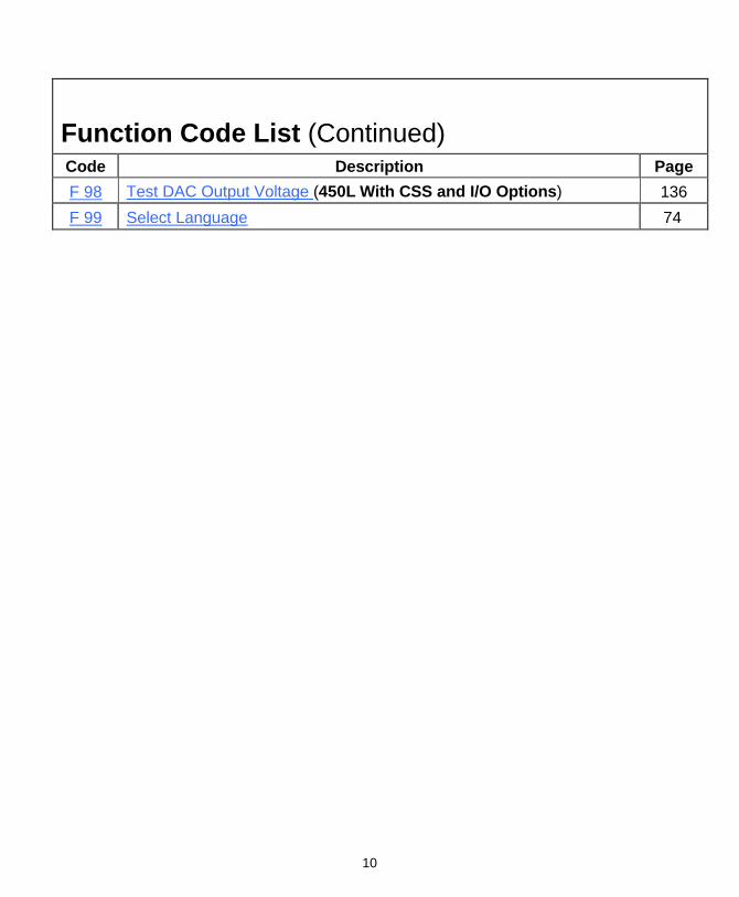
Function Code List (Continued) Code Description Page
F 98 Test DAC Output Voltage (450L With CSS and I/O Options) 136
F 99 Select Language 74

11
Beeper OFF/ON – F 21 The beeper is a standard feature on all ANILAM DROs. Use the beeper to acknowledge a keystroke. For correct keystrokes, a short tone sounds. For incorrect keystrokes, a long tone sounds.
F 21 allows you to enable/disable the beeper in the DRO (Default: ON).
To turn the beeper OFF:
1. Press
The DRO displays the following in the message window:
Beep off
To turn the beeper ON:
1. Press
The DRO displays the following in the message window:
Beep on

12
Keyboard Entry Error If you enter an incorrect value, press the axis key again to clear the axis display. If you enter too many numbers on an axis, the DRO display reverts to zero on that axis. When this happens, enter the correct number again.
13
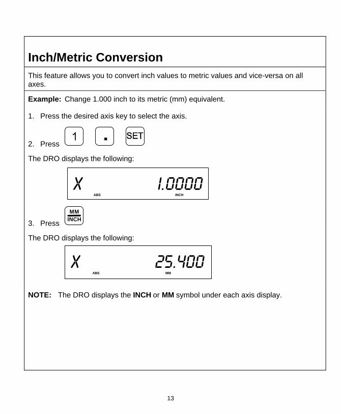
Inch/Metric Conversion This feature allows you to convert inch values to metric values and vice-versa on all axes.
Example: Change 1.000 inch to its metric (mm) equivalent.
1. Press the desired axis key to select the axis.
2. Press
The DRO displays the following:
X i.0000 ABS INCH
3. Press INCHMM
The DRO displays the following:
X 25.400 ABS MM
NOTE: The DRO displays the INCH or MM symbol under each axis display.

14
Decimal Degree to Degree-Minutes-Seconds Conversion You can use every axis to display angular position when you connect a rotary encoder to the DRO. The display range is ±360 degrees.
Note: The axis must be set to rotary using Parameter Settings – F 20.
To convert all angular axis displays from decimal degree display to degree-minutes-seconds display:
1. Press +_

15
Plus/Minus (±) Key The ± key allows you to:
q Change the sign of a preset value.
q Change the direction of travel on a linear encoder while in parameter setting.
q Add and subtract values.
q Scroll through options lists while making selections.
q Scroll through the Advanced Functions (ADV) list.
Plus/Minus Key
7
21
0
3
4 5 6
98
WIZARD 450
CL
ENT
RCL
ADV
SET FINCH
MM ABS
INCR
+-
16
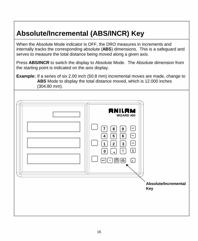
Absolute/Incremental (ABS/INCR) Key When the Absolute Mode indicator is OFF, the DRO measures in increments and internally tracks the corresponding absolute (ABS) dimensions. This is a safeguard and serves to measure the total distance being moved along a given axis.
Press ABS/INCR to switch the display to Absolute Mode. The Absolute dimension from the starting point is indicated on the axis display.
Example: If a series of six 2.00 inch (50.8 mm) incremental moves are made, change to ABS Mode to display the total distance moved, which is 12.000 inches (304.80 mm).
RCL
7
ABSINCR
MMINCHF
21
0
3
4 5 6
98
ADV
WIZARD 450
CL
Absolute/IncrementalKey
+-
SET
ENT

17
Presetting a Dimension Presetting allows you to enter a dimension into an axis display. After you have preset the dimension, you can move the machine until the axis indicates zero.
You can also use the preset feature as a one-line recall mode if the display is set in Incremental Mode.
Example 1: Preset the dimension 1.2500 (31.75 mm) on the axis display.
1. Press the desired axis key.
2. Press to enter the dimension.
3. Press to preset the dimension.
Example 2: Preset the dimension - 1.2500 inches (- 31.75 mm) on one axis display and .5000 (12.7 mm) on another axis display.
1. Press the desired axis key.
2. Press +_
to enter the dimension.
3. Press the desired axis key.
4. Press to enter the dimension.
5. Press to preset the dimension.
NOTE: As a safety feature, the preset axis does not display movement until you press SET. If you press SET after you move the machine, the DRO automatically updates to the new position.

18
Recalling a Preset Dimension This feature allows you to recall a preset dimension to the axis display.
Use this feature when making multiple moves of the same dimension.
NOTE: This feature works only in Incremental Mode.
To recall a preset dimension:
1. Press
ABSINCR
to set the display to Incremental Mode.
2. Press the desired axis keys to select the axes.
3. Enter the incremental dimension.
4. Move the machine to zero.
5. Press the desired axis key twice to recall the dimension.
NOTE: You can recall a dimension after you reset absolute zero or when you have regained power after a power loss.
To clear a preset dimension while in Incremental Mode:
1. Press the desired axis keys to select the axes.
2. Press
19
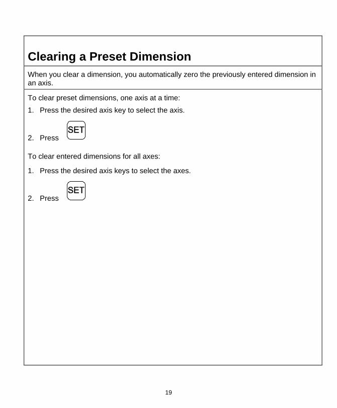
Clearing a Preset Dimension When you clear a dimension, you automatically zero the previously entered dimension in an axis.
To clear preset dimensions, one axis at a time:
1. Press the desired axis key to select the axis.
2. Press
To clear entered dimensions for all axes:
1. Press the desired axis keys to select the axes.
2. Press

20
Resetting an Axis to Zero When you reset an axis, the display for that axis reverts to zero.
Use the reset feature when establishing part zero (datum) or clearing the axis at each part location (making incremental moves).
To reset one axis (X, Y, or Z):
1. Press the desired axis key to select the axis.
2. Press
To reset two or more axes at the same time:
1. Press the desired axis keys to select the axes.
2. Press NOTE: See also Absolute Zero Reset – F 01.

21
Axis Reset Only – F 16 F 16 is useful for quick positioning. Press the axis key once to zero the display in either ABS or INCR Mode.
Example 1: Set one axis as Axis Reset Only (For example, X-axis):
1. Press to select the feature.
The DRO displays the following in the message window:
Axis reset
2. Press the desired axis key to toggle axis reset only
ON (or OFF).
The DRO turns ON the RST symbol in the axis display:
X f i6 RST
3. Press to set the feature.
4. Press the X-axis key to zero the axis display in either ABS or INCR Mode.
NOTE: Perform the same procedure to turn OFF Axis Reset Only.

22
Axis Reset Only – F 16 (Continued) Example 2: Set two or more axes as Axis Reset Only (For example, X-axis and Y-axis):
1. Press to select the feature.
The DRO displays the following in the message window:
Axis reset
2. Press the desired axis key to toggle axis reset only
ON (or OFF).
The DRO turns ON the RST symbol in the axis displays.
Axis Reset OnlyIndicator
X .00000 RST
.00000 RST
Axis Reset OnlyIndicator
3. Press to set the feature.
4. Press the X-axis key to zero the axis display in either ABS or INCR Mode.
NOTE: Perform the same procedure to turn OFF Axis Reset Only.

23
Absolute Zero Set – F 01 F 01 allows you to establish a part zero. The DRO clears all axis counters, both absolute and incremental, to zero.
NOTE: This feature does not clear a preset dimension entered in Incremental Mode. To clear a dimension entered in Incremental Mode, refer to Recalling a Preset Dimension.
To reset all axes to zero:
1. Press
The DRO temporarily displays the following in the message window:
Abs set and then clears the axis displays.
X .0000
.0000

24
Absolute Zero Set at Reference Mark – F 90 F 90 allows you to reset one or more axes to zero at the reference mark. You must use this feature when you use 100-point axis error compensation (F 80/F 81).
To reset all axes at the reference mark:
1. Press
The DRO resets all axis displays and displays the following in the message window:
marker
To reset one axis at the reference mark:
1. Press
2. Press the desired axis key.
3. Press
The DRO resets the specified axis display and displays the following in the message window:
marker

25
EverTrackTM Mode – F 02 F 02 allows you to recall any position that has been previously stored in Absolute Mode, even in case of power outage. In EverTrackTM Mode, the DRO can access absolute references along the linear encoder. As a result, EverTrackTM Mode eliminates the need for a machine home position and a battery backup system.
NOTE: This feature works ONLY with RBS-T and RBM-T linear encoders, which contain absolute reference marks. If your application uses linear encoders without absolute reference marks, disable EverTrackTM Mode (NO E-TRAC) Parameter Settings – F 20.
EverTrackTM Mode can be set either one axis at a time or all axes at a time. If you have a three-axis application but require less than three axes, we recommend that you set the part zero positions one axis at a time.
Setting a Part Zero - One Axis
To set up a part zero position for one axis:
1. Press to select the feature.
The DRO displays the following in the message window:
evertrack
2. Press the desired axis key.
3. Press
The axis display resets to zero and the Reference Indicator (RI) begins to blink.
CAUTION: During the following step, do not change the machine axis travel direction. This will cause an error.
4. Move the machine axis approximately 1 inch (25.4 mm) in one direction until the RI stops blinking and the display starts to count.

26
EverTrackTM Mode – F 02 (Continued) 5. Move the machine axis to the part zero position.
6. Press
This will be the absolute part zero position.
NOTE: You can also preset a dimension as long as the DRO is in Absolute Mode. The zero position corresponding to the stored preset dimension will be stored and can be recalled using EverTrackTM Mode.
CAUTION: If you require a temporary datum while in EverTrackTM Mode, we recommend you exit the feature before you set the temporary datum.
To exit EverTrackTM Mode:
7. Press
8. Press
The RI turns off and the DRO stores the absolute part zero position. Now you can perform an absolute reset (Axis key + SET key) on an axis or an absolute reset (F 01).
Setting a Part Zero – All Axes
To set up a part zero position for all axes:
1. Press to select the feature.
The DRO displays the following in the message window:
evertrack

27
EverTrackTM Mode – F 02 (Continued)
2. Press
The axis displays reset to zero and the RIs begin to blink for each axis.
CAUTION: During the following step, do not change the machine axis travel direction. This will cause an error.
3. Move each machine axis approximately 1 inch (25.4 mm) in one direction until the RIs stop blinking and the display starts to count.
4. Move each machine axis to the part zero position.
5. Press
This will be the absolute part zero position.
NOTE: You can also preset dimensions as long as the DRO is in Absolute Mode. The zero position corresponding to the stored preset dimensions will be stored and can be recalled using EverTrackTM Mode.
To exit EverTrackTM Mode:
6. Press
The DRO displays the following in the message window:
evertrack
7. Press
The RI turns off and the DRO stores the absolute part zero position.
8. Continue with normal operations.

28
EverTrackTM Mode – F 02 (Continued) Recalling a Part Zero Position
To recall a part zero position activate the RI as follows:
One Axis
1. Press to select the feature.
Press the desired axis key.
Press
The axis display resets to zero and the RI begins to blink.
All Axes
1. Press to select the feature.
Press to select all axes.
The axis displays reset to zero and the RIs begin to blink for each axis.
CAUTION: During the following step, do not change the machine axis travel direction. This will cause an error.
2. Move the machine axis approximately 1 inch (25.4 mm) in one direction until the display starts counting.
The value displayed on the axis display indicates the exact distance from the absolute part zero position.
3. Move the machine axis until the display indicates zero.
Zero indicates the exact absolute part zero position.
29
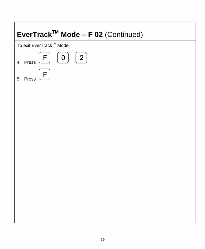
EverTrackTM Mode – F 02 (Continued) To exit EverTrackTM Mode:
4. Press
5. Press

30
Last Position Save/Recall – F 10/F 11 F 10 allows you to save the machine’s last position before turning OFF the machine; F 11 allows you to recall the saved position after turning ON the machine.
NOTE: If you have EverTrackTM Mode, you can always recall all datum points, even if you move the table during power-off.
IMPORTANT: Lock all axes of machine movement first.
To select the feature and save the last position:
1. Press
The DRO displays the following in the message window:
Save pos
2. Turn OFF the DRO power.
To recall the saved position:
1. Turn ON the DRO power.
2. Press to recall the last machine position to the display.
The DRO displays the following in the message window:
recall pos
3. Unlock the machine and continue with the job.
NOTE: This feature stores display information only. It does not track table movement when power is turned OFF.

31
Adding/Subtracting Values This feature allows you to add or subtract values using the axis display values. You can add/subtract a value to/from a value displayed for a machine position or for values you enter in an axis display.
Example 1: The axis display indicates 3.425 inches (87 mm). To add 1.259 inches (32 mm) to this value:
1. Press the desired axis key to select the axis.
2. Press
The axis display now indicates 4.684 (119 mm).
Example 2: To subtract 1.259 inches (32 mm) from 3.425 inches (87 mm) in the axis display:
1. Press the desired axis key to select the axis.
2. Press
3. Press the desired axis key to select the axis.
4. Press +_
The axis display now indicates 2.166 inches (55 mm).

32
Dividing an Axis Value by 2 This feature allows you to divide a value on an axis display by 2. You can also divide any values entered in an axis display by 2.
Example 1: The axis display indicates 7.126 inches (181 mm). To divide this value by 2:
1. Press
2. Press the desired axis key.
The axis display now indicates 3.563 inches (90.5 mm).
Example 2: To divide 1.260 inches (32 mm) by 2 in the axis display:
1. Press the desired axis key.
2. Press
3. Press
4. Press the desired axis key.
The axis display now indicates .630 inches (16 mm). NOTE: You can use this feature to find the center point of a workpiece by zeroing the
tool at one edge of the workpiece, then moving the tool to the opposite edge and dividing by 2.

33
Centering Key The Centering Key allows you to center the tool on the centerline of the workpiece, or on a specific position on the workpiece.
Example: To center the tool on the centerline of the workpiece:
Position 1 Position 2
Position 3
Position 4
Position 1 Position 2
Position 3
Position 4
1. Press to activate the feature.
The DRO displays the following in the message window:
Edge xi
2. Move the tool to position 1.
3. Press ENT
The DRO displays the following in the message window:
Edge x2
4. Move the tool to position 2.
5. Press ENT

34
Centering Key (Continued) The DRO displays the following in the message window:
Edge i
6. Move the tool to position 3.
7. Press ENT
The DRO displays the following in the message window:
Edge 2
8. Move the tool to position 4.
9. Press ENT
10. Move both axes until the displays indicate 0 (zero).
This is the centerline of the workpiece.
To exit the centering feature:
11. Press
NOTE: To center the tool on the centerline of the X-axis only, skip the steps for the Y-axis entries. To center the tool on the centerline of the Y-axis only, press the Y-axis key after you press the centering key.

35
Radius/Diameter per Axis – F 05 F 05 allows you to display a specified axis in Radius or diameter mode. The DRO doubles axis movement and resolution In Diameter Mode. (Default for 450L: ON)
Example 1: Set one axis display in diameter mode.
1. Press to select the feature.
The DRO displays the following in the message window:
Rad -- dia
2. Press the desired axis key to select the axis.
The DRO displays the radius-diameter mode indicator in the selected axis display.
Radius-DiameterMode Indicator
X f 05
3. Press to activate the feature.
Example 2: Set two or more axis displays in diameter mode.
1. Press to select the feature.
The DRO displays the following in the message window:
Rad -- dia

36
Radius/Diameter per Axis – F 05 (Continued) 2. Press the desired axis keys to select the axes.
The DRO displays the radius-diameter mode indicator in the selected axis displays.
Radius-DiameterMode Indicator
X f 05
Radius-DiameterMode Indicator
3. Press to activate the feature.
To turn Diameter Mode OFF:
1. Press
2. Press the axis key(s).
The DRO turns OFF the radius-diameter mode indicator symbol(s), indicating the radius-diameter mode is turned off.
37
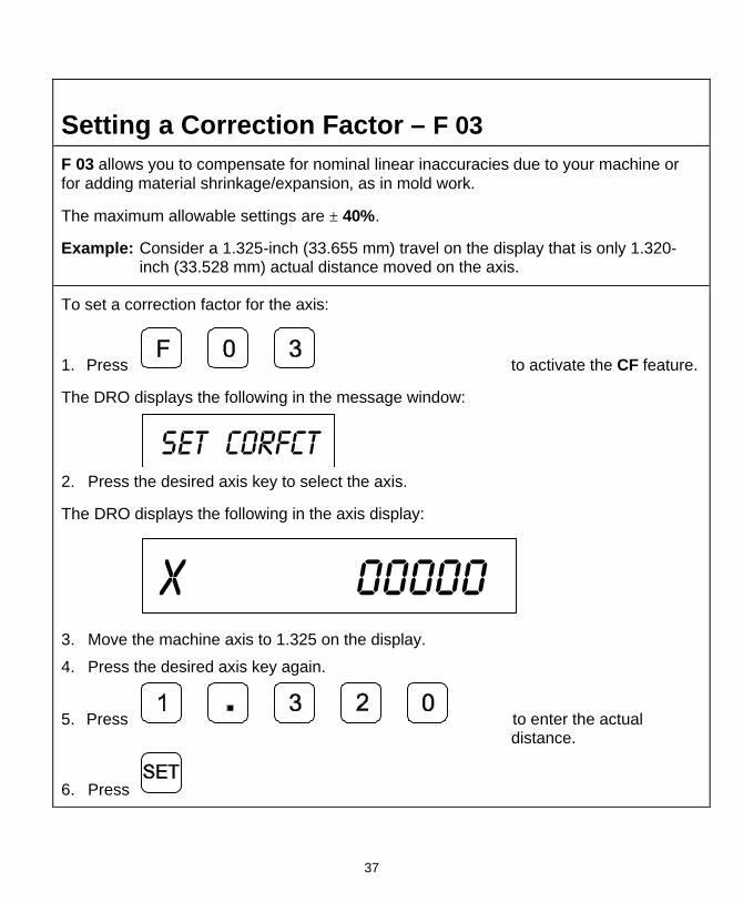
Setting a Correction Factor – F 03 F 03 allows you to compensate for nominal linear inaccuracies due to your machine or for adding material shrinkage/expansion, as in mold work.
The maximum allowable settings are ± 40%.
Example: Consider a 1.325-inch (33.655 mm) travel on the display that is only 1.320-inch (33.528 mm) actual distance moved on the axis.
To set a correction factor for the axis:
1. Press to activate the CF feature.
The DRO displays the following in the message window:
Set corfct
2. Press the desired axis key to select the axis.
The DRO displays the following in the axis display:
X 00000
3. Move the machine axis to 1.325 on the display.
4. Press the desired axis key again.
5. Press to enter the actual distance.
6. Press

38
Setting a Correction Factor – F 03 (Continued) The Correction Factor (CF) indicator in the displayed axis turns ON indicating the Correction Factor is active.
X i.320
CF

39
100-Point Axis Error Compensation – F 80/F 81 F 80/F 81 allow you to correct non-linear errors. The DRO allows setting a compensation table with a maximum of 100 different points per axis. This feature allows you to compensate for machine tool inaccuracies.
To determine the compensation values it is necessary to measure the axis with a Laser Interferometer or other measuring device.
Axis Error Compensation is only possible if the Reference mark evaluation is activated (EverTrackTM).
1. Press
2. Press the desired axis key and
3. Move the linear encoder for the axis across the reference mark until RI stops blinking and the display starts to count.
Measure the Axis
To measure the axis, switch the DRO to mode “REFERENCE DISPLAY”.
1. Press
The DRO displays the following in the message window:
SEL AXIS

40
100-Point Axis Error Compensation F 80/F 81 (Continued)
Measure the Axis (Continued)
2. Press the desired axis key.
3. Press
ABSINCR
key.
The DRO displays the following in the message window:
REF.DISPLAY
The decimal point in the left display field indicates that the display values are referenced to the Reference mark. If the decimal point blinks, the Reference mark has not been traversed.
Now, if required, you can set a zero to datum point for the “Reference Display”.
For example, press the desired axis and
Press to set zero point for “Reference Display”.
Measure the axis and note the compensation values for later programming.
As the compensation is always related to the “Reference Display”, you are not allowed to change the zero or datum point for the “Reference Display” after measuring.
Press to leave the “Reference Display” mode.
41
100-Point Axis Error Compensation F 80/F 81 (Continued)
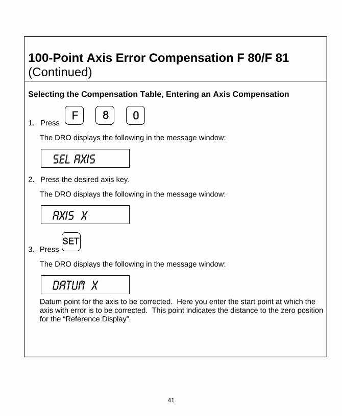
Selecting the Compensation Table, Entering an Axis Compensation
1. Press
The DRO displays the following in the message window:
SEL AXIS
2. Press the desired axis key.
The DRO displays the following in the message window:
AXIS X
3. Press
The DRO displays the following in the message window:
Datum X
Datum point for the axis to be corrected. Here you enter the start point at which the axis with error is to be corrected. This point indicates the distance to the zero position for the “Reference Display”.

42
100-Point Axis Error Compensation F 80/F 81 (Continued) Selecting the Compensation Table, Entering an Axis Compensation (Continued)
Enter, for example: 0 mm
Press
The DRO displays the following in the message window:
SPacing X
Enter the spacing between the compensation points. Factory setting: 10 mm
Enter, for example: 5 mm
Press
The DRO displays the following in the message window:
X NO. oo
. 0.000 X-axis display shows compensation point no. 0
0.000 Y-axis display shows compensation value no. 0
NOTE: Compensation point 0 always has the compensation value 0 and cannot be changed.

43
100-Point Axis Error Compensation F 80/F 81 (Continued) Selecting the Compensation Table, Entering an Axis Compensation (Continued)
Press
The DRO displays the following in the message window:
X NO. o1
. 5.000 X-axis display shows compensation point no. 1
- - - - - - - - - Y-axis display shows compensation value no. 0
Enter the associated compensation value for point no. 1 and confirm with SET. For example: 0.002 mm
Press
Press
The DRO displays the following in the message window:
X NO. o2
Repeat this procedure for all further compensation points (no. 2 – no. 99).

44
100-Point Axis Error Compensation F 80/F 81 (Continued) Selecting the Compensation Table, Entering an Axis Compensation (Continued)
NOTE: For 1-axis version, the compensation point displays only briefly in axis display, before compensation value is shown. If you press, the CE key, the compensation point is shown again.
Key Functions for Compensation Table
SET key: Confirm entry and page forward in the compensation table
MMINCH MM/INCH key: Page backward in the compensation table.
ABSINCR
ABS/INCR key: Change to “REFERENCE DISPLAY” mode.
ADV ADV key: Direct selection of compensation points.
Press the ADV key and the two-digit number of the desired compensation point.
Exit the compensation table.

45
100-Point Axis Error Compensation F 80/F 81 (Continued)
Deleting a Compensation Value Table
To delete a compensation value table:
1. Press
The DRO displays the following in the message window:
SEL AXIS
2. Select the table for the specified axis with the axis key.
The DRO displays the following in the message window:
AXIS X
3. Press c
The DRO displays the following in the message window:
DELETE X
Delete the compensation value table with key, or cancel with c
key.

46
100-Point Axis Error Compensation F 80/F 81 (Continued)
Axis Error Compensation ON/OFF
1. Press
The DRO displays the following in the message window:
99 - pt.activ
A programmed error compensation can be switched ON or OFF for each axis with the axis key. If compensation is active, the red symbol “CF” in the corresponding display is on.

47
Correction Factor OFF/ON – F 04 F 04 allows you to turn the Correction Factor (CF) OFF or ON selectively and store the values in memory.
To turn the correction factor ON or OFF:
1. Press to select the feature.
The DRO displays the following in the message window:
Cf on--off
2. Press the desired axis key to select the axis to enable or disable CF.
3. If necessary, turn the correction factor ON or OFF for any axis.
To clear the correction factor from memory:
1. Press
The DRO displays the following in the message window:
Set corfct
2. Press the desired axis key to select the axis to clear.
3. Press the axis key twice to clear the CF.
4. Press

48
Approaching Zero Indicator This feature indicates that the machine is within a set range and is approaching zero.
The approaching zero indication range must be set using Approaching Zero Range – F 07.
X .0000 Approaching ZeroIndicator
Apz set

49
Approaching Zero – F 06 F 06 indicates when an axis is within a set range and approaching zero, or at zero.
1. Press to select the feature.
The DRO displays the following in the message window and axis displays:
X f 06
Apz set
2. Press the desired axis keys to select the axes.
The DRO displays the approaching zero indicator(s) on the selected axis display(s).
X f 06
Apz set
3. Press to activate the feature.

50
Approaching Zero – F 06 (Continued)
To turn the approaching zero indicator OFF:
1. Press to select the feature.
2. Press the desired axis key to deselect the axis.
3. Press
NOTE: The following example shows an axis with an approaching zero position tolerance set to .5. The symbols in the lower right corner of the display indicate the axis is approaching zero, at zero, or past zero. The arrows indicate the direction of travel toward zero only if you preset a range using Approaching Zero Range – F 07.
X .50000
Approaching zero.
X .00000
At zero.
X -.50000
Past zero.

51
Approaching Zero Range – F 07 F 07 allows you to set the range for approaching zero indication in one or more axes.
Example: To set the range for the X-axis to .5:
1. Press to select the feature.
The DRO displays the following in the message window:
Apz range
The axis displays indicate the current approaching zero range.
2. Press axis 1 key to select the axis.
The DRO displays the following in the axis display:
X 0
The X is blinking.
3. Press
The DRO displays the following in the axis display:
X .5

52
Approaching Zero Range – F 07 (Continued) To set the range for another axis:
4. Repeat steps 2 and 3 for each axis.
5. Press to activate the feature.

53
Approaching Zero Audio ON/OFF – F 08 F 08 enables/disables an audible beep to notify you when the selected axis is within the approaching zero range. (Default: OFF)
To turn on audio notification for the selected axis:
1. Press
The DRO displays the following in the message window:
Apz audio
To turn off audio notification for the selected axis:
1. Press
The DRO displays the following in the message window:
Apz--no--aud

54
Connecting the Edge Sensor Probe
CAUTION: To avoid electrical shock, unplug the DRO from the power source.
1. Connect the ground wire on the back of the DRO to a proper earth ground.
2. Place the round spring clip in the appropriate groove on the probe.
NOTE: Ensure that the round spring clip on the probe cable is connected to the probe below the LED.
3. Plug the other end of the probe cable into the circular jack on the back of the DRO.
The red LED on the probe should glow dimly, indicating a proper connection. When you touch the probe tip to the workpiece, the red LED should glow brightly.

55
Edge Sensor Probe – F 09 F 09 allows you to position the spindle on the edge of the workpiece.
To activate the edge sensor probe:
1. Press
The DRO displays the following in the message window:
Probe edge
NOTE: When you move the X-axis from left to right, enter a positive diameter; when you move the X-axis from right to left enter a negative diameter (See Figure 5).
X+ X-
Y-
Y+Center of Spindle
Figure 5: Choosing Direction of Movement
Example: To enter a probe diameter of .2 Inches (5.08 mm) for the X-axis (moving from left to right):
2. Press the axis key to select the axis.
The DRO displays the following in the message window:
Probe dia

56
Edge Sensor Probe – F 09 (Continued) To enter the probe diameter:
3. Press +_
to toggle to plus or minus, for the desired direction of movement (See Figure 5).
4. Press
The DRO displays the following in the message window and axis display:
Probe x +
X .0000Edge Sensor Indicator
5. Move the edge sensor until it touches the edge of the workpiece and the edge sensor indicator turns off.
6. Move the spindle until the axis display indicates zero.
This is the edge of the workpiece.

57
Feedrate ON/OFF – F 26 F 26 allows you to display the maximum feedrate for all axes in the message window (if feedrate is greater than 0.4 inches per minute or greater than 10 mm per minute). The DRO displays the feedrate in inches per minute if set to INCH mode and mm per minute if set to MM mode. If you move two or more axes at the same time, the DRO displays the feedrate for the fastest moving axis. (Default: OFF)
To turn on the feedrate:
1. Press
The DRO displays the following in the message window:
Feed on
To turn off the feedrate:
1. Press
The DRO displays the following in the message window:
Feed off

58
Job Clock ON/OFF – F 34 F 34 allows you to toggle the DROs integrated job clock ON or OFF. When activated, the job clock displays the time in hours, minutes, and seconds in the message window. (Default: OFF)
To turn the job clock ON:
1. Press
The DRO temporarily displays the following in the message window:
Clock on
The DRO resets the axis display windows to zero and displays the job clock in the message window.
Jc 00.00.00
To start or stop the job clock:
2. Press
To reset the job clock to 0 (zero):
3. Press
To redisplay the message window and run the job clock in the background or to redisplay the job clock:
4. Press +_

59
Job Clock ON/OFF – F 34 (Continued) To turn the job clock OFF:
1. Press
The DRO displays the following in the axis display window:
Clock off
The DRO clears the job clock display in the message window and resets the axis display windows to 0 (zero).

60
Parameter Settings – F 20 F 20 allows you to set up encoder parameters and axis display resolutions. To avoid confusion, it is important to know that here we refer to two different types of resolution, namely:
q Encoder Resolution the resolution of the measurement, an encoder parameter. q Display Resolution the resolution of displayed values.
You can vary the resolution of the dimensions displayed in the linear axis displays for both INCH and MM mode. In case of a rotary axis, you can set up the display resolution for degrees in both decimal and minutes/seconds format. You can set the display resolution individually for each axis.
F 20 allows you to enter specific properties for the encoders that are used for feedback. These can be set up individually for each axis. Your DRO will support three different types of encoders:
q Metric Linear Encoders (encoders with grating pitch measured in microns, µm)
q Inch-Based Linear Encoders (encoders with grating pitch measured in inches)
q Rotary Encoders
All modern linear encoders are of the Metric type.
Setting Up Encoder Parameters To enter encoder and axis display parameters:
1. Press to select the feature.
The DRO displays the following in the message window:
parameter
2. Press the desired axis key(s) to select the axis (axes).

61
Parameter Settings – F 20 (Continued) NOTE: You can select one or more axes to set up simultaneously as long as they use
the same encoders and the same display format is desired. You must repeat the F 20 feature and select the appropriate axis (axes) for each different type of encoder setup.
The DRO displays the following in the message window:
Met--in--rot
and the DRO displays one of the following in the selected axis display:
metric
inch
rot
3. Press +_
to scroll through the encoder type options and set the desired encoder type.

62
Parameter Settings – F 20 (Continued) NOTE: Most linear encoders, and all modern ANILAM encoders are metric, i.e., they
have a grating pitch measured in microns (µm). Some older linear encoders (for example, BT and JB type encoders) have a grating pitch measured in inches. Select rot if the encoder is a rotary encoder.
Go to the section for the selected type of encoder:
q Metric Linear Encoders q Inch Linear Encoders
q Rotary Encoders
Metric Linear Encoders
If you have performed steps 1 through 3 in the Setting Up Encoder Parameters section and selected Metric Linear Encoder, the DRO prompts for the encoder resolution and direction of positive travel in the message window, and displays the default encoder resolution (5µm) in the axis display:
X 5.000000
ABS MM
Res -- dir + --
The axis designation (in this example, X) is blinking, indicating that you can enter a value. The default value for the encoder resolution is 5µm. This value must be exact for the specific encoder you are using for feedback.

63
Parameter Settings – F 20 (Continued) The following table lists the encoder resolution (in microns) for common ANILAM encoders:
Linear Encoder Type Encoder Resolution RBS-05T, RBM-05T .5
RBS-1, RBS-1T, RBM-1T, B-1, E-1 1
RBS-2, A-2, C-2, E-2, F-2, 2
RBS-5, RBS-5T, RBM-5T, PGS-E, PGS-P, B-5, C-5, E-5, KM-5, 5 5 micron resolution Rack and Pinion
RBS-10, A-10, C-10, D-10, KM-10 10 10 micron resolution Rack and Pinion
NOTE: If the table does not list the linear encoder type/resolution for the linear encoder(s) you are using, and you do not know the exact encoder resolution, call ANILAM for advice. If you are using BT or JB linear encoders (inch linear encoders) refer to the Inch Linear Encoders section.
If you need to change the encoder resolution setting:
1. Enter the correct setting (in microns) for the encoder you are using.
If you need to change the direction of positive travel:
2. Press +_
to change the direction of positive travel.
3. Press to set the encoder resolution and direction of travel.

64
Parameter Settings – F 20 (Continued) The DRO displays the following in the message window and axis display(s):
X .005
ABS MM
Resol mm
Coarse Resolution Symbol
This is the display resolution setting for the axis display(s) when the MM/INCH key has been toggled to MM mode only. The axis designation is blinking, indicating that you can enter a value. The DRO will default the same display resolution as the encoder resolution (in this example, .005 MM). ANILAM recommends that you use the same display resolution as the encoder resolution.
4. Press +_
to scroll through the display resolution options in MM mode.
The display resolution options for MM mode are:
.0002, .0005, .001, .002, 005, .01, .02, .05, .1, .2, .5 MM
NOTE: If the selected display resolution is coarser than the encoder resolution, the DRO turns on the Coarse Resolution Symbol in the axis display(s).
5. Press to select the desired display resolution in MM mode.

65
Parameter Settings – F 20 (Continued) The DRO displays the following in the message window and axis display:
X
ABS INCH
Resol inch
Coarse Resolution Symbol
This is the display resolution setting for the axis display(s) when the MM/INCH key has been toggled to INCH mode only. The axis designation is blinking, indicating that you can enter a value. The DRO will default the same display resolution as the encoder resolution (in this example, .0002 in.). ANILAM recommends that you use the display resolution that best matches the encoder resolution.
6. Press +_
to scroll through the display resolution options in INCH mode.
The display resolution options for Inch Mode are: .00001, .00002, .00005, .0001, .0002, .0005, .001, .002, .005, .01, .02 Inches
NOTE: If the selected display resolution is coarser than the encoder resolution, the DRO turns on the Coarse Resolution Symbol in the axis display(s).
7. Press to select the desired display resolution in INCH mode.

66
Parameter Settings – F 20 (Continued) The DRO displays the following in the message window:
e—trac set
to set up EverTrackTM
mode.
and the displays one of the following in the selected axis display:
Setting Linear Encoder i20 r05 RBS-05T and RBM-05T only i20 r1 RBS-1T and RBM-1T only i20 r5 RBS-5T and RBM-5T (default) no E-trac All other linear encoders
8. Press +_
to scroll through the options.
9. Press to set the option and exit.
To reset all parameter settings to the original factory configuration:
10. Press for approximately 5 seconds (Press F again to cancel the reset).
11. Press to reset all parameters.

67
Parameter Settings – F 20 (Continued) Inch Linear Encoders (BT or JB Linear Encoders)
If you have performed steps 1 through 3 in the Setting Up Encoder Parameters section and selected Inch Linear Encoder, you are using BT or JB linear encoders (inch linear encoders) for feedback.
The DRO prompts for the encoder resolution and direction of positive travel in the message window:
X 000000
ABS MM
Res -- dir + --
The axis designation (in this example, X) is blinking, indicating that you can enter a value. The default value for the encoder resolution is .0001 in. (The display shows the value in ten thousands of an inch). This value must be exact for the specific encoder you are using for feedback.
NOTE: If you do not know the exact encoder resolution, call ANILAM for advice.
If you need to change the encoder resolution setting:
1. Enter the correct setting (in ten thousands of an inch) for the encoder you are using.
For example, if the encoder resolution is .0002 in. (two thousands of an inch):
2. Press
If you need to change the direction of positive travel:
3. Press +_
to change the direction of positive travel.
4. Proceed to step 6 in the Metric Linear Encoders section and follow the procedures.

68
Parameter Settings – F 20 (Continued) Rotary Encoders
If you have performed steps 1 through 3 in the Setting Up Encoder Parameters section and selected Rotary Encoder (rot), the DRO prompts for the Line Count in the message window. The default rotary encoder line count (9000) is displayed in the axis display:
W 9000
Line count
ABS
The axis designation (in this example, W) is blinking, indicating that you can enter a value. The default value for the encoder line count is 9000. This value must be exact for the specific encoder you are using for feedback.
If you need to change the line count:
1. Enter the correct setting for the rotary encoder you are using.
If you need to change the direction of positive rotation:
2. Press +_
to change the direction of positive rotation.
3. Press to set the encoder line count.
69
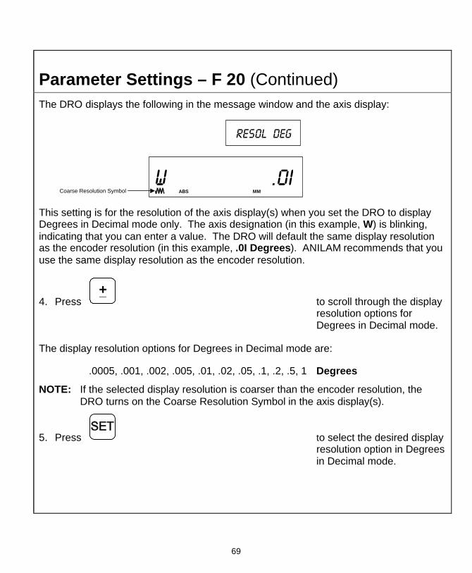
Parameter Settings – F 20 (Continued) The DRO displays the following in the message window and the axis display:
w .0i
ABS MM
Resol deg
Coarse Resolution Symbol
This setting is for the resolution of the axis display(s) when you set the DRO to display Degrees in Decimal mode only. The axis designation (in this example, W) is blinking, indicating that you can enter a value. The DRO will default the same display resolution as the encoder resolution (in this example, .0I Degrees). ANILAM recommends that you use the same display resolution as the encoder resolution.
4. Press +_
to scroll through the display resolution options for Degrees in Decimal mode.
The display resolution options for Degrees in Decimal mode are:
.0005, .001, .002, .005, .01, .02, .05, .1, .2, .5, 1 Degrees
NOTE: If the selected display resolution is coarser than the encoder resolution, the DRO turns on the Coarse Resolution Symbol in the axis display(s).
5. Press to select the desired display resolution option in Degrees in Decimal mode.

70
Parameter Settings – F 20 (Continued) The DRO displays the following in the message window and the axis display:
w .00.30
Min--sec
ABS
This setting is for the resolution for the axis display(s) when you set the DRO to display Degrees in Minutes and Seconds mode only. The axis designation (in this example, W) is blinking, indicating that you can enter a value. The DRO will default the display resolution that best matches the encoder (in this example, 30 seconds). ANILAM recommends that you use the display resolution that best matches the encoder resolution.
6. Press +_
to scroll through the display resolution options for Degree in Minutes and Seconds mode.
The display resolution options for Degrees in Minutes and Seconds mode are:
.00.01, .00.02, .00.05, .00.10, .00.20, .00.30, .01, .02, .05, .10, .20 Min.Sec
NOTE: If the selected display resolution is coarser than the encoder resolution, the DRO turns on the Coarse Resolution Symbol in the axis display(s).
7. Press to select the desired display resolution option for Degrees in Minutes and Seconds mode, and exit the feature.

71
Parameter Settings – F 20 (Continued) To reset all parameter settings to the original factory configuration:
8. Press for approximately 5 seconds (Press F again to cancel the reset).
9. Press to reset all parameters.

72
Display Dim OFF/ON – F 22/F 23 F 22 allows you to activate Dim Mode; F 23 allows you to deactivate Dim Mode. To increase the life of the display, the DRO automatically dims if it is not used for 15 minutes (similar to a computer terminal’s screen-saver mode). When you activate Dim Mode the axis displays show blinking decimal points. The DRO remains in Dim Mode until you press a key or move one or more linear encoders. (Default: ON)
To select DIM ON:
1. Press
The DRO displays the following in the message window:
Dim on
To select DIM OFF:
1. Press
The DRO displays the following in the message window:
Dim off
NOTE: You can disable this feature, however the DRO still goes into Dim Mode after standing idle for one hour.
73
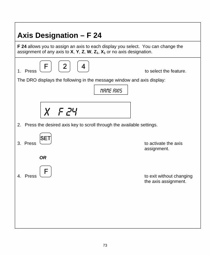
Axis Designation – F 24 F 24 allows you to assign an axis to each display you select. You can change the assignment of any axis to X, Y, Z, W, Z1, X1 or no axis designation.
1. Press to select the feature.
The DRO displays the following in the message window and axis display:
Name axis
X f 24
2. Press the desired axis key to scroll through the available settings.
3. Press to activate the axis assignment.
OR
4. Press to exit without changing the axis assignment.

74
Select Language – F 99 F 99 allows you to select the language the DRO will use to display text and messages.
The available languages are:
q English q German q French q Italian q Spanish q Swedish q Czech q Portuguese
To select the language:
1. Press
The DRO displays the selected language in the message window:
english
2. Press +_
to scroll through the options.
3. Press to select the language.
75
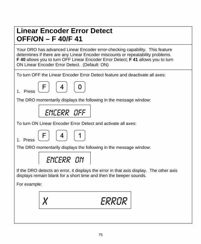
Linear Encoder Error Detect OFF/ON – F 40/F 41 Your DRO has advanced Linear Encoder error-checking capability. This feature determines if there are any Linear Encoder miscounts or repeatability problems. F 40 allows you to turn OFF Linear Encoder Error Detect; F 41 allows you to turn ON Linear Encoder Error Detect. (Default: ON)
To turn OFF the Linear Encoder Error Detect feature and deactivate all axes:
1. Press
The DRO momentarily displays the following in the message window:
Encerr off
To turn ON Linear Encoder Error Detect and activate all axes:
1. Press
The DRO momentarily displays the following in the message window:
Encerr on
If the DRO detects an error, it displays the error in that axis display. The other axis displays remain blank for a short time and then the beeper sounds.
For example:
X error

76
Diagnostics – F 45 F 45 allows you to perform system diagnostic tests on the keyboard, internal EEPROM, and internal counters. If any of these tests fail, contact your local distributor or ANILAM Customer Services. You do not need to unplug the linear encoders for these tests.
Display Test
1. Press to display all segments of the display and message window.
EEProm Test
2. Press to activate the internal EEPROM test.
The DRO displays the results in the axis window:
EEProm nF (no fail). EEPR. FAIL
Counters Test
3. Press to activate the internal counters test.
The DRO displays the results in the axis window:
Count nF (no fail). CNT FAIL

77
Diagnostics – F 45 (Continued) Keyboard Test
4. Press to activate the keyboard test.
5. Press any key on the DRO to display the key on the DRO display.
Blank Test
6. Press for 2 seconds to blank all segments of the display.
7. Press to end the system diagnostics test.

78
Advanced (ADV) Functions Key The Advanced Functions Key allows you to access the following DRO advanced functions:
q Help for DRO Features
q Bolt-Hole Patterns (450 only) q Linear-Hole/Frame Hole Patterns (450 only) q Taper Calculation (450L only)
To access the Advanced functions:
1. Press ADV
The DRO displays the following in the message window:
HELP
To scroll through the functions list:
2. Press ADV
Help Function
HELP allows you to scroll through a list of feature names and their codes or quickly access a DRO feature from the list.
To display the list of features and their codes:
1. Press ENT
The DRO displays the following in the message window:
PRESS + --

79
Advanced (ADV) Functions Key (Continued) To scroll through the feature list:
2. Press +_
The DRO displays the following in the message window and axis display 1:
ABS SET
F0I
Each time you press the plus/minus key, the DRO displays the next feature code in axis display 1 and the feature name in the message window.
To reverse the scrolling direction:
3. Press +_
To activate a displayed feature:
4. Press ENT
To exit the Help function:
5. Press

80
Advanced (ADV) Functions Key (Continued) Bolt-Hole Pattern Function (450 Only)
The Bolt-Hole Pattern function allows you to program the X and Y positions for a maximum of 10 different bolt-hole patterns (maximum 360 holes each) around the circumference of a specified circle. The 450 DRO can program the following types of bolt-hole patterns:
q Partial Pattern In a partial pattern, the holes do not cover the entire circumference of the circle. Instead they form an arc, called a partial pattern. (See Figure 1)
q Full Pattern In a full pattern, the holes cover the entire circumference of the circle. (See Figure 2)
Y
1.00 Inch
X0
Hole 1
Hole 3
90 o
-10 o
Diameter: 1.00 Inch (25.4 mm)Beginning Angle: -10 o
End Angle: 80 o
Holes: 3X Center: 1.00 Inch (25.4 mm)Y Center: 1.00 Inch (25.4 mm)
1.00 Inch
Hole 2
Figure 1: Partial Bolt-Hole Pattern

81
Advanced (ADV) Functions Key (Continued)
0
Diameter: 2.00 inches (50.8 mm)Beginning Angle: -10 o
Holes: 4X Center: +1.00 inch (25.4 mm)Y Center: +1.00 inch (25.4 mm)
0 o
1.00 Inch
-10 o
X
Y
Hole 1
Hole 2
Hole 4
Hole 3
1.00 Inch
Figure 2: Full Bolt-Hole Pattern
To access the Bolt-Hole pattern function:
1. Press ADV
ADV
to scroll through the Advanced Functions list.
When the DRO displays the following in the message window:
BOLT HOLE
2. Press ENT
The DRO displays the following in the message window:
BHP NUMBER

82
Advanced (ADV) Functions Key (Continued) Note: If you are entering a full bolt-hole pattern, skip this section and go to the
Full Bolt-Hole Pattern section.
Partial Bolt-Hole Pattern
To enter a partial bolt-hole pattern for program number 1 (Range is 0 through 9):
1. Press ENT
The DRO displays the following in the message window:
FULL
To enter a partial bolt-hole pattern:
2. Press +_
The DRO displays the following in the message window:
Partial
3. Press ENT
The DRO displays the following in the message window and axis display 1:
X CENTER
X .0000

83
Advanced (ADV) Functions Key (Continued) To enter the X dimension for the center of the pattern. For example, 1.00 inch (25.4 mm):
4. Press ENT
The DRO displays the following in the message window and axis display 2:
.0000
CENTER
To enter the Y dimension for the center of the pattern. For example, 1.00 inch (25.4 mm):
5. Press ENT
The DRO displays the following in the message window and axis display 1:
BHP DIA
X .0000 To enter the diameter of the bolt-hole pattern. For example, 1.00 inch (25.4 mm):
6. Press ENT

84
Advanced (ADV) Functions Key (Continued)
The DRO displays the following in the message window and axis display 1:
X 0
QT HOLE
To enter the number of bolt-hole patterns (maximum 360 holes). For example, 3:
7. Press ENT
The DRO displays the following in the message window and axis display 1:
BEG ANGLE
X .0000
To enter the beginning angle for the first hole (measured in a counter clockwise direction) For example: -10 degrees
8. Press +_
ENT
The DRO displays the following in the message window and axis display 1:
END ANGLE
X 360.0

85
Advanced (ADV) Functions Key (Continued) To enter the end angle for the pattern (measured in a counter clockwise direction), for example, for 80 degrees:
9. Press ENT
The DRO temporarily displays the following in the message window:
Bhp done

86
Advanced (ADV) Functions Key (Continued)
Full Bolt-Hole Pattern (450 Only)
To access the Full Bolt-Hole Pattern function:
1. Press ADV
ADV
to scroll through the Advanced Functions list.
When the DRO displays the following in the message window:
BOLT HOLE
2. Press ENT
The DRO displays the following in the message window:
BHP NUMBER
To enter a full bolt-hole pattern for program number 2 (Range is 0 through 9):
3. Press ENT
The DRO displays the following in the message window:
partial
4. Press +_
87
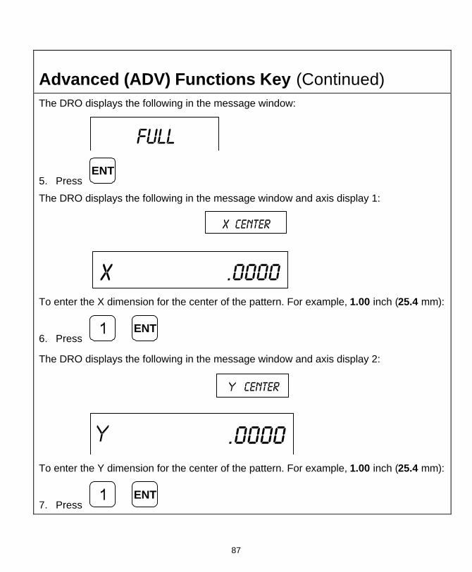
Advanced (ADV) Functions Key (Continued) The DRO displays the following in the message window:
full
5. Press ENT
The DRO displays the following in the message window and axis display 1:
X CENTER
X .0000 To enter the X dimension for the center of the pattern. For example, 1.00 inch (25.4 mm):
6. Press ENT
The DRO displays the following in the message window and axis display 2:
.0000
CENTER
To enter the Y dimension for the center of the pattern. For example, 1.00 inch (25.4 mm):
7. Press ENT

88
Advanced (ADV) Functions Key (Continued) The DRO displays the following in the message window and axis display 1:
BHP DIA
X .0000 To enter the diameter of the bolt-hole pattern. For example, 2.00 inches (50.8 mm):
8. Press ENT
The DRO displays the following in the message window and axis display 1:
X 0
QT HOLE
To enter the number of bolt-hole patterns (maximum 360 holes). For example, 4:
9. Press ENT
The DRO displays the following in the message window and axis display 1:
BEG ANGLE
X .0000
89
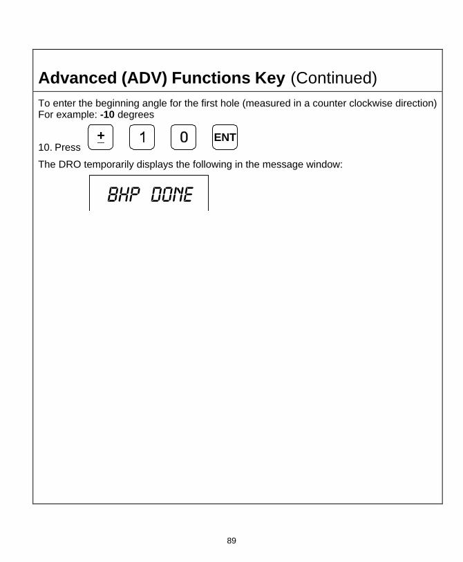
Advanced (ADV) Functions Key (Continued) To enter the beginning angle for the first hole (measured in a counter clockwise direction) For example: -10 degrees
10. Press +_
ENT
The DRO temporarily displays the following in the message window:
Bhp done

90
Advanced (ADV) Functions Key (Continued)
Recalling Bolt-Hole Pattern Function (450 Only)
The Recall Key (RCL) allows you to recall a maximum of 10 previously programmed bolt–hole patterns.
To recall bolt-hole pattern number 1 programmed in the previous section:
1. Press ADV
ADV
to scroll through the Advanced Functions list.
When the DRO displays the following in the message window:
Bolt hole
2. Press
The DRO displays the following in the message window:
BHP NUMBER
3. Press ENT

91
Advanced (ADV) Functions Key (Continued) The DRO displays the following in the message window and the axis displays:
I HOLE 00i
X - i.4924
- .9i32
The message window indicates bolt-hole pattern number 1 and hole number 1. The axis displays show the distance to hole number 1.
4. Move the machine until the axis displays indicate zero and drill the hole.
To recall the distance to hole number 2:
5. Press
The DRO displays the following in the axis displays and the message window:
2 HOLE 002
X + .0828
- .3736
92
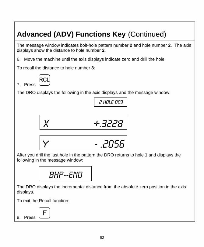
Advanced (ADV) Functions Key (Continued) The message window indicates bolt-hole pattern number 2 and hole number 2. The axis displays show the distance to hole number 2.
6. Move the machine until the axis displays indicate zero and drill the hole.
To recall the distance to hole number 3:
7. Press
The DRO displays the following in the axis displays and the message window:
2 HOLE 003
X +.3228
- .2056 After you drill the last hole in the pattern the DRO returns to hole 1 and displays the following in the message window:
BHP--end
The DRO displays the incremental distance from the absolute zero position in the axis displays.
To exit the Recall function:
8. Press
93
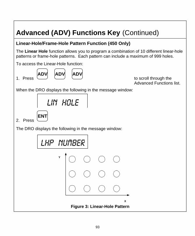
Advanced (ADV) Functions Key (Continued) Linear-Hole/Frame-Hole Pattern Function (450 Only)
The Linear Hole function allows you to program a combination of 10 different linear-hole patterns or frame-hole patterns. Each pattern can include a maximum of 999 holes.
To access the Linear-Hole function:
1. Press ADV
ADV
ADV
to scroll through the Advanced Functions list.
When the DRO displays the following in the message window:
LIN HOLE
2. Press ENT
The DRO displays the following in the message window:
Lhp NUMBER
X
Y
Figure 3: Linear-Hole Pattern

94
Advanced (ADV) Functions Key (Continued) To program a linear-hole pattern (For example, linear-hole pattern number 3 (Range is 0 through 9):
3. Press
The DRO displays the following in the message window:
lin hole
If you are programming a linear-hole pattern go to step 5.
X
Y
Figure 4: Frame-Hole Pattern
To select Frame-Hole Pattern:
4. Press +_
The DRO displays the following in the message window:
frame hole

95
Advanced (ADV) Functions Key (Continued) To enter a frame-hole pattern:
5. Press ENT
The DRO displays the following in the message window:
X hole i
To enter the dimension for hole 1 on the X-axis. For example, 1.00 inch (25.4 mm):
6. Press ENT
The DRO displays the following in the message window:
hole i
To enter the dimension for hole 1 on the Y-axis. For example, 1.00 inch (25.4 mm):
7. Press ENT

96
Advanced (ADV) Functions Key (Continued) The DRO displays the following in the message window:
Qt hole x To enter the number of holes on the X-axis. For example, 4:
8. Press ENT
The DRO displays the following in the message window:
X -- X cent
To enter the incremental distance between holes on the X-axis. For example, 1.00 inch (25.4 mm):
9. Press ENT
The DRO displays the following in the message window:
Qt hole To enter the number of holes on the Y-axis. For example, 4:
10. Press ENT

97
Advanced (ADV) Functions Key (Continued) The DRO displays the following in the message window:
-- cent
To enter the incremental distance between holes on the Y-axis. For example, 1.00 inch (25.4 mm):
11. Press ENT
The DRO displays the following in the message window:
X004 004
The message window indicates the calculated holes in the X-axis (4 holes) and the Y-axis (4 holes). This equals a total of 16 holes (4 X-holes x 4 Y-holes). The maximum number of holes you can program is 999 holes.
To activate the settings and exit the Frame Hole function:
12. Press
OR
To exit the Frame-Hole function without activating the settings:
13. Press ENT
98
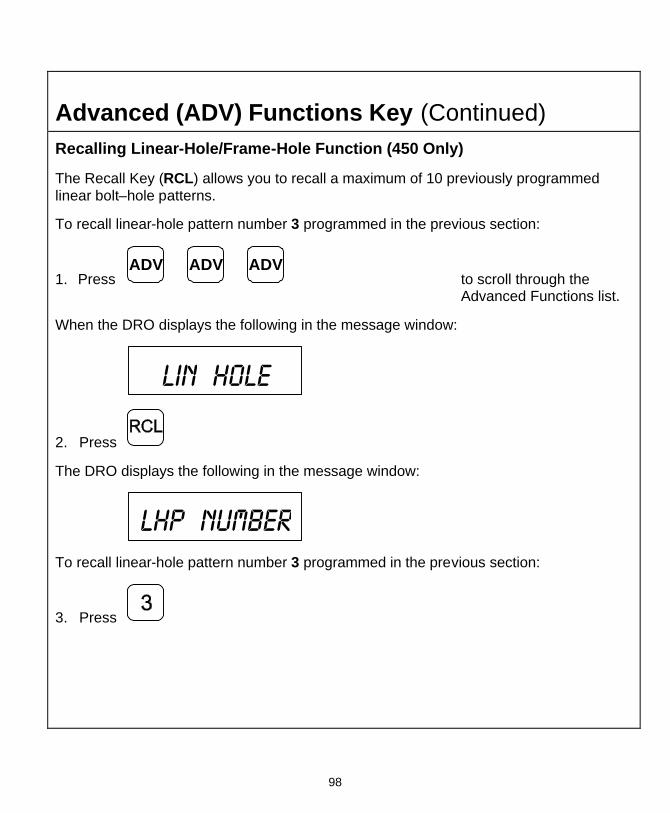
Advanced (ADV) Functions Key (Continued) Recalling Linear-Hole/Frame-Hole Function (450 Only)
The Recall Key (RCL) allows you to recall a maximum of 10 previously programmed linear bolt–hole patterns.
To recall linear-hole pattern number 3 programmed in the previous section:
1. Press ADV
ADV
ADV
to scroll through the Advanced Functions list.
When the DRO displays the following in the message window:
Lin HOLE
2. Press
The DRO displays the following in the message window:
lHP NUMBER
To recall linear-hole pattern number 3 programmed in the previous section:
3. Press

99
Advanced (ADV) Functions Key (Continued) The DRO displays the following in the axis displays and the message window:
I HOLE 00i
X - i.9848
- .8264
The message window indicates bolt-hole pattern number 1 and hole number 1. The axis displays show the distance to hole number 1.
4. Move the machine until the axis displays indicate zero and drill the hole.
To recall the distance to hole number 2:
5. Press
The DRO displays the following in the axis displays and the message window:
2 HOLE 002
X +.8 I I 0
- i. I 584

100
Advanced (ADV) Functions Key (Continued) The message window indicates bolt-hole pattern number 2 and hole number 2. The axis displays show the distance to hole number 2.
6. Move the machine until the axis displays indicate zero and drill the hole.
7. Repeat these procedures until you have completed all holes in the linear-hole pattern.
To exit the Recall Linear-Hole Pattern function:
8. Press
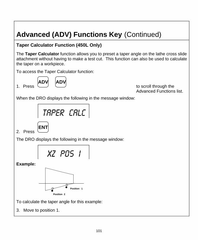
101
Advanced (ADV) Functions Key (Continued) Taper Calculator Function (450L Only)
The Taper Calculator function allows you to preset a taper angle on the lathe cross slide attachment without having to make a test cut. This function can also be used to calculate the taper on a workpiece.
To access the Taper Calculator function:
1. Press ADV
ADV
to scroll through the Advanced Functions list.
When the DRO displays the following in the message window:
Taper calc
2. Press ENT
The DRO displays the following in the message window:
XZ Pos i Example:
2Position
1Position
To calculate the taper angle for this example:
3. Move to position 1.

102
Advanced (ADV) Functions Key (Continued)
4. Press ENT
The DRO displays the following in the message window:
XZ Pos 2 5. Move to position 2.
6. Press ENT
The DRO displays the taper angle in the message window:
+ 28.i38 deg
2Position
1Position
Calculated angle: 28.138 degrees
To exit the Taper Calculator function:
7. Press or ENT

103
Datum Key (450 Only) The Datum Key allows you to enter a datum table (maximum 99 datum points). A datum is a point or reference location, from which you can machine a part. Datum points allow you to machine similar programs on different parts. After you machine a group of parts, you can place a new group on the machine and machine the same programs on the new parts.
Note: Before you enter a datum table you must establish a machine home position using Absolute Zero Set – F 01 or activate EverTrackTM Mode – F 02.
Example:
Y
XMachineHomePosition
Part 3
Part 2
Part 1
2 Inches(50.8 mm)
1 Inch(25.4 mm)
1 Inch(25.4 mm)
2 Inches(50.8 mm)
3 Inches(76.2 mm)
4 Inches(101.6 mm)
Enter Datum
To enter a datum table for the above example:
1. After power on, establish a machine home position using Absolute Zero Set – F 01 or activate EverTrackTM Mode – F 02.
2. Move the tool to the home position (indicated by the black dot).
3. Establish a part zero using Absolute Zero Set – F 01.
Datum 0, machine home is set.
4. Move the tool to the corner of part 1 (indicated by the black dot).

104
Datum Key (450 Only) (Continued)
5. Press
The DRO displays the following in the message window:
Datum 00
6. Press
The DRO displays the following in the message window:
Datum 0i
7. Establish a part zero using Absolute Zero Set – F 01.
Datum 1 is set.
8. Move the tool to the corner of part 2 (indicated by the black dot).
9. Press
The DRO displays the following in the message window:
Datum 0i
10. Press
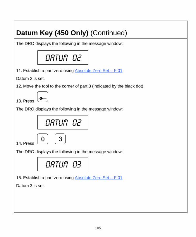
105
Datum Key (450 Only) (Continued) The DRO displays the following in the message window:
Datum 02
11. Establish a part zero using Absolute Zero Set – F 01.
Datum 2 is set.
12. Move the tool to the corner of part 3 (indicated by the black dot).
13. Press
The DRO displays the following in the message window:
Datum 02
14. Press
The DRO displays the following in the message window:
Datum 03
15. Establish a part zero using Absolute Zero Set – F 01.
Datum 3 is set.

106
Datum Key (450 Only) (Continued) Enter Datum (Alternate Method)
If you know the axis locations for the corner of the parts, you can enter the datum table for the previous example without moving the tool from the machine home position as follows:
1. After power on, establish a machine home position using Absolute Zero Set – F 01 or activate EverTrackTM Mode – F 02.
To enter datum 1:
2. Press
3. Press the axis key for the X-axis.
4. Press to enter the X-axis value, .5 inch (12.7 mm).
5. Press the axis key for the Y-axis.
6. Press to enter the Y-axis value, .5 inch (12.7 mm).
7. Press to set datum 1.
To enter datum 2:
8. Press

107
Datum Key (450 Only) (Continued) 9. Press the axis key for the X-axis.
10. Press to enter the X-axis value, 2 inches (50.8 mm).
11. Press the axis key for the Y-axis.
12. Press to enter the Y-axis value, 1 inch (25.4 mm).
13. Press to set datum 2.
To enter datum 3:
14. Press
15. Press the axis key for the X-axis.
16. Press to enter the X-axis value, 3.5 inches (88.9 mm).
17. Press the axis key for the Y-axis.
18. Press to enter the Y-axis value, 1.5 inches (38.1 mm).
19. Press to set datum 3.

108
Datum Key (450 Only) (Continued) Recall Datum
Recall Datum allows you to recall a preset datum.
Example: To recall datum 1 from the previous example:
1. Press
While the datum is activated, the DRO displays the following in the message window:
Datum 0i
2. Move the X-axis and Y-axis until the axis displays indicate zero (0).
This is the location for Datum 1.
3. Perform the machine process on part 1.
To return to the machine home position (datum 0):
4. Press
5. Move the X-axis and Y-axis until the axis displays indicate zero (0).
This is the location for the machine home position (datum 0).

109
Datum Key (450 Only) (Continued) Clear Datum – F 31
Clear Datum (F 31) allows you to clear all preset datum points (maximum 99) before entering new information.
To clear all datum points:
1. Press
The DRO temporarily displays the following in the message window:
Del datum
When the DRO resets the message window and axis displays, all preset datum values are cleared from memory.

110
Tool Offset Key (450L Only) The Tool Offset Key allows you to preset X and Z offsets for each tool into a tool table (maximum 99). This feature requires an interchangeable tool system.
Note: Before entering a tool offset you must establish a machine home position using Absolute Zero Set – F 01 or activate EverTrackTM Mode – F 02.
Workpiece
Tool Number 1
Tool Number 2
Tool Holder atHome Position
Z
X
Enter Tool Offset
Example: To enter an offset for a tool:
1. Press
The DRO displays the following in the message window:
Tool 00
To select the tool number, (For example, tool number 1):
2. Press
The DRO displays the following in the message window:
Tool 0i

111
Tool Offset Key (450L Only) (Continued)
2.376 Inches (56.35 mm)
1.00 Inch (25.4 mm)
Tool Number 1Inside Workpiece
Tool Number 1at Corner ofWorkpiece
Z Axis ZeroReference Point
3. Move the tool to the workpiece and make a skim cut on the diameter, about 1 inch
(25.4 mm), to allow a micrometer to measure the workpiece.
4. Measure the diameter of the workpiece. The measurement in the example is 2.376 inches (56.35 mm).
5. Move the tool to the corner of the workpiece or any known position as illustrated in the example.
To preset the tool offset:
6. Press the axis key for the X-axis.
7. Press
8. Move the tool to the Z-axis reference point.
To store this reference point:
9. Press the axis key for the Z-axis.
10. Press
The offset for tool number 1 is preset.
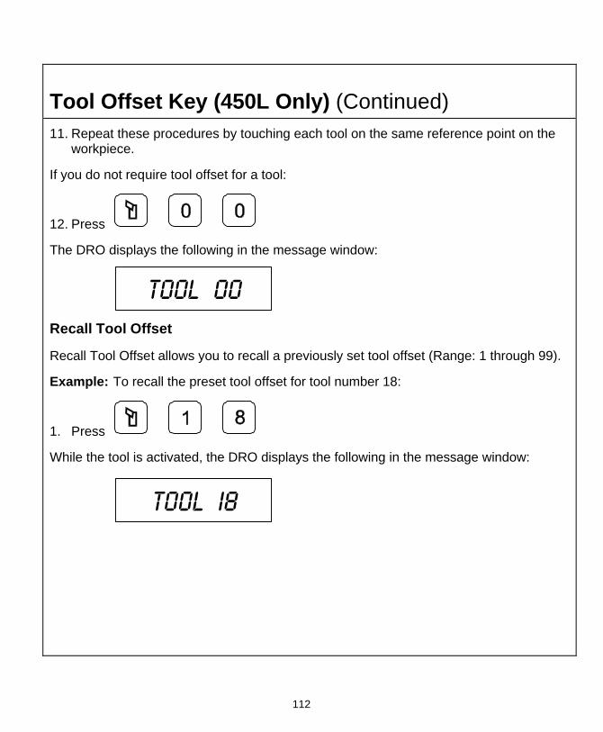
112
Tool Offset Key (450L Only) (Continued) 11. Repeat these procedures by touching each tool on the same reference point on the
workpiece.
If you do not require tool offset for a tool:
12. Press
The DRO displays the following in the message window:
Tool 00
Recall Tool Offset
Recall Tool Offset allows you to recall a previously set tool offset (Range: 1 through 99).
Example: To recall the preset tool offset for tool number 18:
1. Press
While the tool is activated, the DRO displays the following in the message window:
Tool i8

113
Tool Offset Key (450L Only) (Continued) Modify Tool Offset – F 35
Modify Tool Offset (F 35) allows you to modify the Z-axis tool-offset value for all tools without reentering values. If you place a new part with a different length in the chuck, you must modify all the Z-axis tool offsets in the tool table.
Note: To modify the tool offset, a tool number must be activated.
Example: To modify the Z offset to 5.0:
1. Press
The DRO displays the following in the message window:
Tool mod
2. Press the axis key for the Z-axis.
3. Press to activate the feature.

114
Tool Offset Key (450L Only) (Continued) Clear Tool Offset – F 32
Clear Tool Offset (F 32) allows you to clear all preset tool offset values (99 tools) before entering new information.
To clear all preset tool offset values:
1. Press
The DRO displays the following in the message window:
Del Tool
When the DRO resets the message window and axis displays, all preset tool offset values are cleared from memory.

115
Axis Coupling (450L, 3-Axis Only) – F 18 F 18 allows you to sum two parallel axes (Z + Z1, Z + W, or Y + Z) on one axis. This allows you to move the coupled axes independently while the DRO automatically calculates the true tool position. This feature is valid only on three-axes DROs.
Example:
To sum axis 2 and axis 3:
1. Press to select the feature.
The DRO temporarily displays following in the message window:
Coup on
The DRO clears the COUP ON message and displays the following in the message window:
Z + zi
To turn off axis coupling:
1. Press
The DRO displays the following in the message window:
Coup off

116
Output Connections (With I/O Option Only) Output connections are located on the back of the DRO. When DRO functions are activated, the DRO generates signals through these connections to operate external devices.
Each output can sink 500 mA of current when active. The output load of Relay 1 and Relay 2 should be a maximum of 10 VA (maximum 20 Volts, 0.75 A).
1 2 3 4 5 6 7 8
9 10 11 12 13 14 15
DA 15 Connector (Male)
Pin 1 Relay 1 Output Pin 9 Relay 2 Output Pin 2 Relay 1 Output Pin 10 Approaching Zero Pin 3 X-Axis Zero Pin 11 Y-Axis Zero Pin 4 Z-Axis Zero Pin 12 Relay 2 Output Pin 5 W-Axis Zero Pin 13 Ground Pin 6 Ground Pin 14 +24 Volts Pin 7 +24 Volts Pin 15 DAC Output for CSS Pin 8 Analog Ground for DAC Output (0-10 Volt/10mA, 12 Bit, galv.
isolated)
The output connections, X-axis zero, Y-axis zero, Z-axis zero, W-axis zero, and approaching zero are enabled by applying a constant +24 VDC, 50 mA source to pin 7 and pin 14 and a ground to any of two ground pins.
When outputs are enabled, pin 3, pin 4, pin 5, and pin 11 generate a 24-V common signal as the corresponding axis value is zero. Pin 10 generates a 24-V common signal within a set range of an axis zero. The 24-V common output is generally used to complete a relay control circuit.

117
Input Connections (With I/O Option Only) Input connections are located on the back of the DRO. These connections allow signals from external devices to activate specific DRO functions.
DRO functions are activated by applying a +24 VDC, 10 mA signal for a minimum of 100 ms. Inputs to the DRO are optically coupled for protection. The Ground pin is the reference ground for the inputs and should always be used.
32 41 5
6 7 8 9
DE 9 Connector (Male)
Pin 1 X-Axis Zero Pin 2 Z-Axis Zero Pin 3 Recall (RCL Key for remote operations) Pin 4 Not Used Pin 5 Ground Pin 6 Y-Axis Zero Pin 7 Store (ENT Key for remote operations) Pin 8 Print Pin 9 Not Used

118
Zero Output ON/OFF (With I/O Option Only) – F 33 F 33 allows you to toggle the zero output ON or OFF. (Default: OFF)
To turn the zero output ON:
1. Press
The DRO displays the zero output setting in each axis display and the following in the message window:
Zero out
2. Press the desired axis key to toggle the zero output
setting ON or OFF.
3. Press to activate the setting.

119
Approaching Zero Output Axis (With I/O Option Only) – F 14 F 14 allows you to specify which axis the DRO will use for approaching zero (APZ) output. When the selected axis is within the range preset using Approaching Zero Range – F 07, the DRO turns on the output.
To specify the axis for APZ output:
1. Press
The DRO displays the following in the message window:
Apz out
NOTE: You can select only one axis for APZ output.
2. Press the desired axis key to toggle the axis ON.
The DRO displays the following in the selected axis display:
To exit without specifying the axis for APZ output:
3. Press
To set the axis for APZ output:
4. Press

120
Zero Output Time Select (With I/O Option Only) – F 25 F 25 allows you to specify the time for which a remote device is turned on when the selected axis crosses zero. (Default: 100 ms) Zero Output – F 33 must be ON.
To change the setting:
1. Press to select the feature.
The DRO displays the following in the message window:
i00 ms
The DRO displays the last-entered setting in the message window.
The available settings are:
Zero Output Time Settings 30 ms, 100 ms (default), 200 ms, 300 ms, 400 ms, 500 ms, 600 ms, 700 ms, 800 ms, 900 ms, and 1 second
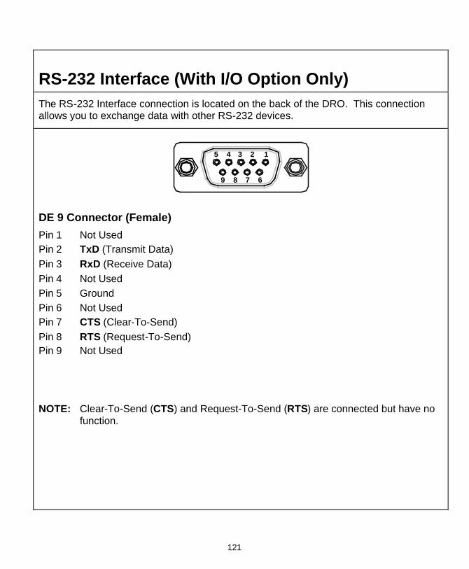
121
RS-232 Interface (With I/O Option Only) The RS-232 Interface connection is located on the back of the DRO. This connection allows you to exchange data with other RS-232 devices.
3 24 15
6789
DE 9 Connector (Female)
Pin 1 Not Used Pin 2 TxD (Transmit Data) Pin 3 RxD (Receive Data) Pin 4 Not Used Pin 5 Ground Pin 6 Not Used Pin 7 CTS (Clear-To-Send) Pin 8 RTS (Request-To-Send) Pin 9 Not Used
NOTE: Clear-To-Send (CTS) and Request-To-Send (RTS) are connected but have no function.
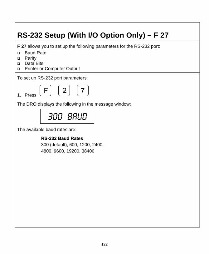
122
RS-232 Setup (With I/O Option Only) – F 27 F 27 allows you to set up the following parameters for the RS-232 port: q Baud Rate q Parity q Data Bits q Printer or Computer Output
To set up RS-232 port parameters:
1. Press
The DRO displays the following in the message window:
300 baud
The available baud rates are:
RS-232 Baud Rates 300 (default), 600, 1200, 2400, 4800, 9600, 19200, 38400
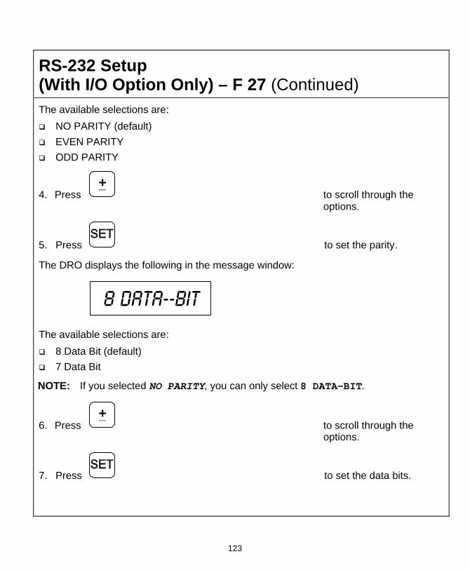
123
RS-232 Setup (With I/O Option Only) – F 27 (Continued) The available selections are:
q NO PARITY (default)
q EVEN PARITY q ODD PARITY
4. Press +_
to scroll through the options.
5. Press to set the parity.
The DRO displays the following in the message window:
8 data--bit
The available selections are:
q 8 Data Bit (default) q 7 Data Bit
NOTE: If you selected NO PARITY, you can only select 8 DATA-BIT.
6. Press +_
to scroll through the options.
7. Press to set the data bits.

124
RS-232 Setup (With I/O Option Only) – F 27 (Continued) The DRO displays the following in the message window:
printer
The available selections are:
q PRINTER (default) Each output of a string ends with a Carriage Return (CR) and a Line Feed (LF).
q COMPUTER Each output of a string ends with a Carriage Return (CR).
8. Press +_
to toggle between the options.
9. Press to set the output.
OR
10. Press to exit without change.

125
RS-232 ON/OFF (With I/O Option Only) – F 28 F 28 allows you to toggle the RS-232 port ON or OFF. (Default: OFF)
To toggle the RS-232 port ON:
1. Press
The DRO displays the following in the message window:
Rs 232 on
To toggle the RS-232 port OFF:
1. Press
The DRO displays the following in the message window:
Rs 232 off

126
Printing Axis Values (With I/O Option Only) NOTE: Before sending data to the printer, ensure that the DRO is not in the Preset
Mode.
To print axis values to a printer:
1. Press to print the data from axis 1.
2. Press to print the data from axis 2.
3. Press to print the data from axis 3.
4. Press to print the data from all axes.
Printed Axis Value Format The DRO prints the axis values in the following format:
Axis value unit of measurement counting mode diameter mode
Examples: X -123.456 mm ABS D Y 454.902 in INC W -235.125 dms (dms = degree-min-sec)
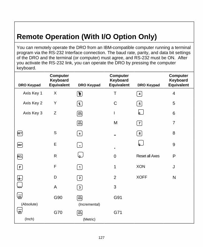
127
Remote Operation (With I/O Option Only) You can remotely operate the DRO from an IBM-compatible computer running a terminal program via the RS-232 Interface connection. The baud rate, parity, and data bit settings of the DRO and the terminal (or computer) must agree, and RS-232 must be ON. After you activate the RS-232 link, you can operate the DRO by pressing the computer keyboard.
DRO Keypad
Computer Keyboard Equivalent DRO Keypad
Computer Keyboard Equivalent DRO Keypad
Computer Keyboard Equivalent
Axis Key 1 X T 4
Axis Key 2 Y C 5
Axis Key 3 Z ABSINCR
I 6
MMINCH M 7
S
- 8
E
. 9
R
0 Reset all Axes P
F
1 XON J
D
2 XOFF N
ADV A 3
ABSINCR
(Absolute)
G90 ABSINCR (Incremental)
G91
MMINCH
(Inch)
G70 MMINCH
(Metric) G71
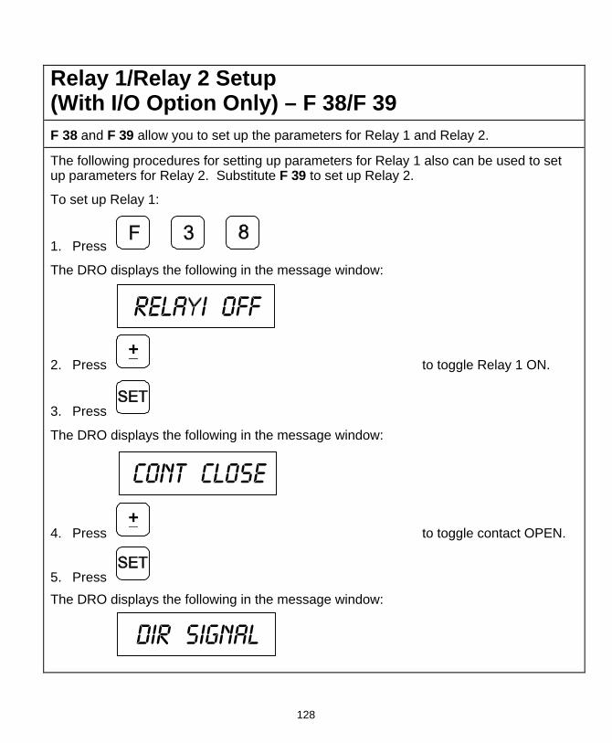
128
Relay 1/Relay 2 Setup (With I/O Option Only) – F 38/F 39 F 38 and F 39 allow you to set up the parameters for Relay 1 and Relay 2.
The following procedures for setting up parameters for Relay 1 also can be used to set up parameters for Relay 2. Substitute F 39 to set up Relay 2.
To set up Relay 1:
1. Press
The DRO displays the following in the message window:
Rela i off
2. Press +_
to toggle Relay 1 ON.
3. Press
The DRO displays the following in the message window:
Cont close
4. Press +_
to toggle contact OPEN.
5. Press
The DRO displays the following in the message window:
Dir signal

129
Relay 1/Relay 2 Setup (With I/O Option Only) – F 38/F 39 (Continued)
6. Press +_
to toggle between Direct Signal and Coincidence Pulse.
7. Press
If you select Coincidence Pulse, you can change the output time. The available output times for Coincidence Pulse are:
Coincidence Pulse Output Time 100 ms (default), 500 ms, 1 sec, 2 sec, 3 sec, 4 sec, 5 sec, 10 sec, 30 sec, 1 min, 2 min, 5 min, 10 min
8. Press +_
to scroll through the options.
9. Press to select the Coincidence Pulse output time.
The DRO displays the following in the message window:
Sel axis

130
Relay 1/Relay 2 Setup (With I/O Option Only) – F 38/F 39 (Continued) 10. Press the desired axis key.
11. Press to enter the value for the switch off point.
NOTE: You can assign each relay to each axis.
Selectable Output TimeSwitch off ValueSwitch off Value
Coincidence Pulse
+ -
Direction Signal

131
Output Test (With I/O Option Only) – F 42 F 42 allows you to test the following available DRO outputs:
q X ZERO OUT
q Y ZERO OUT q Z ZERO OUT q APZ OUT
q RELAY 1 q RELAY 2
If any of these tests fail, contact your local distributor or ANILAM Customer Services.
To start the output tests:
1. Press
The DRO turns on each available output for approximately 1 second. The message window displays the name of each output test and the beeper sounds a short beep when each test is complete.
To return to normal operation:
2. Press

132
Constant Surface Speed (CSS) Setup (450L With CSS and I/O Options) If your DRO has the CSS option, you can use the DAC (Digital/Analog Converter) output voltage to control the spindle speed. You can vary the DAC output voltage between 0V and 10V with 12-bit resolution. A maximum of 5 different gears can be set up.
Use the following F-codes to set up the CSS feature:
F 96 DAC Output Voltage Setup F 97 DAC Output Voltage Offset Adjustment F 98 DAC Output Voltage Test

133
DAC Output Voltage Setup (450L With CSS and I/O Options) – F 96 F 96 allows you to set up the DAC output voltage.
To set up the CSS feature:
1. Press to select DAC voltage setup.
The DRO displays the following in the message window:
Rpm 0v gi
prompting for the spindle speed at 0V for Gear 1.
To enter the spindle speed at 0V for Gear 1 (For example, 0 RPM):
2. Press
The DRO displays the following in the message window:
Min Rpm gi
prompting for the minimum spindle speed at 0V for Gear 1.
To enter the minimum allowed spindle speed for Gear 1 (For example, 25 RPM):
3. Press
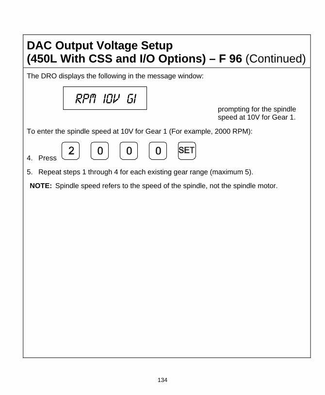
134
DAC Output Voltage Setup (450L With CSS and I/O Options) – F 96 (Continued) The DRO displays the following in the message window:
Rpm i0v gi
prompting for the spindle speed at 10V for Gear 1.
To enter the spindle speed at 10V for Gear 1 (For example, 2000 RPM):
4. Press
5. Repeat steps 1 through 4 for each existing gear range (maximum 5).
NOTE: Spindle speed refers to the speed of the spindle, not the spindle motor.

135
DAC Output Voltage Offset Adjustment (450L With CSS and I/O Options) – F 97 F 97 allows you to adjust the DAC output voltage offset. You will require a digital multimeter to perform this feature.
To set up the CSS feature:
1. Connect a multimeter to Pin 15 and Pin 8 and measure the DAC output voltage.
2. Press
The DRO displays the following in the message window:
Dac offset
The DRO displays a value between 0 and 50 in the axis display. To change the output voltage, change this value.
To adjust the DAC offset to exactly 0mV:
3. Press +_
repeatedly until the multimeter indicates 0 mV.
To reverse the scrolling direction:
4. Press +_
To enter the adjusted DAC output voltage:
5. Press

136
DAC Output Voltage Test (450L With CSS and I/O Options) – F 98 F 98 allows you to verify the DAC output voltage setting.
To verify DAC output voltage setting:
1. Connect a multimeter between Pin 15 and Pin 8 and measure the DAC output voltage.
2. Press
The DRO displays the following in the message window:
Dac test
3. Press to display 0V on the axis display.
4. Press to display 5V on the axis display.
5. Press to display 10V on the axis display.
NOTE: The displayed DAC output voltage must be within 100mV of the nominal values.

137
Constant Surface Speed (CSS)/Direct RPM Operation (450L With CSS and I/O Options) If your DRO has the CSS option, you can use the DAC (Digital/Analog Converter) output voltage to control the spindle speed. You can use this feature in Lathe Mode to obtain a constant surface speed as the tool changes the workpiece diameter.
Use the following F-codes to operate the CSS feature:
F 48 CSS/Direct RPM Input F 50 DAC Output Voltage On/Off
NOTE: The CSS feature must be set up properly.
NOTE: Do not start the spindle with the DRO (For example, using F 50). The machine should have a separate switch for this purpose.

138
CSS/Direct RPM Input (450L With CSS and I/O Options) – F 48 F 48 allows you to specify the desired Constant Surface Speed (CSS), which is entered in Feet per Minute (INCH Mode) or Meters per Minute (MM Mode). The DRO maintains the specified constant surface speed as the diameter of the workpiece changes. You can specify a maximum spindle speed (MAX SPEED) to restrict the spindle speed from exceeding this speed as the diameter decreases, or a specific spindle speed (DIRECT RPM) to maintain the spindle speed at a constant RPM.
To program a CSS operation:
1. Select a tool by using the Tool Offset.
2. Press
The DRO displays one of the following in the message window (depending on the number of available gears):
Gear i Gear 2
3. Press +_
to toggle and select the desired gear.
The DRO displays the following in the message window:
Max speed
NOTE: The DRO limits the spindle speed to the top speed entered during DAC Output Voltage Setup (F 96). MAX SPEED is used if the part requires a lower maximum spindle speed than the preset top speed for the selected gear. When you select a new gear, the DRO uses the corresponding top speed as the default MAX SPEED.

139
CSS/Direct RPM Input (450L With CSS and I/O Options) – F 48 (Continued) To limit the spindle speed (For example, to 2500 RPM):
4. Press
NOTE: The decimal point at the left of the X-axis display will blink if the spindle speed is limited by MAX SPEED.
The DRO displays one of the following in the message window:
Css on Direct rpm
The available selections are:
q CSS ON Activates the CSS feature. The DRO varies the spindle speed to maintain a constant surface speed as the workpiece diameter changes.
q DIRECT RPM The DRO maintains the spindle speed at a constant RPM.
5. Press +_
to toggle between the settings and to set the feature.
NOTE: If you select DIRECT RPM, skip to the DIRECT RPM section. If you select CSS ON, continue with the CSS ON section below.
CSS ON
If you selected CSS ON, the DRO displays the following in the message window:
Cs--speed

140
CSS/Direct RPM Input (450L With CSS and I/O Options) – F 48 (Continued) The X-axis display indicates the previously used surface speed. The X designation is blinking, indicating you can enter a value.
If the displayed surface speed is acceptable:
6. Press to continue.
OR
To set a new surface speed (For example, 200 RPM):
7. Press
NOTE: Surface speed must be entered in Feet per Minute when the DRO is set to INCH Mode or Meters per Minute when the DRO is set to MM Mode.
DIRECT RPM
If you selected DIRECT RPM, the DRO displays the following in the message window:
Speed MAN
prompting for the desired spindle speed.
To set the spindle speed (For example, 2500 RPM):
6. Press

141
CSS/Direct RPM Input (450L With CSS and I/O Options) – F 48 (Continued) If the displayed surface speed is acceptable:
7. Press to continue.
OR
To set a new surface speed (For example, 200 RPM):
8. Press to set the surface speed.
NOTE: Surface speed must be entered in Feet per Minute when the DRO is set to INCH Mode or Meters per Minute when the DRO is set to MM Mode.
If you selected DIRECT RPM, the DRO displays the following in the message window:
Speed MAN
prompting for the desired spindle speed.
To set the spindle speed (For example, 2500 RPM):
9. Press to set the spindle speed.

142
DAC Output Voltage ON/OFF (450L With CSS and I/O Options) – F 50 F 50 allows you to turn the DAC output voltage ON or OFF:
To turn the DAC output voltage ON or OFF:
1. Press
The DRO displays one of the following in the message window:
DAC off DAC OUt on
2. Press +_
to turn the DAC output voltage ON or OFF.
NOTE: Do not turn the spindle ON or OFF using F 50. The machine should have a separate switch for this purpose.

143
Troubleshooting This section lists problems that could arise with the DRO, and provides possible solutions to correct these problems.
Symptom q Axis display does not illuminate. q When you move any axis, the displays
do not update.
q When you press a key, the beeper does not sound.
Solution 1. Check that the power cord is properly
connected and the DRO is turned on.
2. Check the AC voltage. 3. If all of the above are checked and
OK, contact your local distributor or ANILAM Customer Services.
1. Check that the linear encoders are
properly connected. 2. Run the system diagnostic tests
(F 45). 3. If the DRO fails the diagnostics tests,
contact your local distributor or ANILAM Customer Services.
4. If the DRO passes the diagnostics tests, turn on Linear Encoder Error Check (F 41).
5. Move the axis that is not updating. 6. If the DRO displays ERROR in the axis
display, contact your local distributor or ANILAM Customer Services.
1. Verify that the Beeper (F 21) is
enabled. 2. If the Beeper is enabled, but still does
not sound, contact your local distributor or ANILAM Customer Services.

144
Troubleshooting (Continued) Symptom
q When the power is turned OFF, information in memory is lost.
q The DRO does not retain the set parameters as they were entered.
q Information recalled is incorrect.
q The DRO does not respond when you press a key or several keys.
Solution 1. Contact your local distributor or
ANILAM Customer Services.
Index-1
Index 100-point axis error compensation
– F 80/F 81, 24, 39
A ABS/INCR key, 16 absolute zero set, 23 absolute zero set at reference
mark – F 90, 24 absolute/incremental key, 16 ABSolute/INCRemental key, 2 AC voltage, 143 AC voltage fuse cover window, 3 acknowledging a keystroke, 11 adding values, 15 adding/subtracting values, 31 ADVanced functions key, 2, 78 approaching zero, 50 approaching zero – F 06, 49 approaching zero audio
on/off – F 08, 53 approaching zero indicator, 48 approaching zero output axis
select – F 14, 119 approaching zero range – F 07,
51 APZ OUT, 131 APZ output, specify axis, 119 at zero, 50 audible keyboard tone, 5 avoiding, electrical shock, 54 axis
coupling – F 18, 115 designation – F 24, 73 displays, 2 error compensation, ON/OFF, 46 keys, 2
reset only – F 16, 21 to measure, 39
B back panel, Wizard 450, 3 baud rate, 122, 127 beeper, 75, 143 beeper OFF/ON – F 21, 11 blank test, 77 bolt-hole pattern, 78, 80 BT or JB linear encoders, 67
C cables, 6 calculating the taper on a
workpiece, 101 centering key, 2, 33 CF feature, 37 CF indicator, 38 changing
the direction of travel in parameter setting, 15 the sign of a preset value, 15
checklist, first-time user, 5 clear
a preset dimension, 19 correction factor from memory, 47 datum – F 31, 109 tool offset – F 32, 114
coarse resolution symbol, 64, 65, 69, 70
coincidence pulse output time options, 129
compensation table key functions, description, 44 selecting, 41, 44 to delete, 45 computer output, 122

Index
Index-2
connecting, the probe, 54 connections, linear encoders,
ground, power cord, 3 console display, 4 constant surface speed (CSS),
138 constant surface speed, setup,
132 convert, inch values to metric
values, 13 correct keystrokes, 11 correction factor, 37 correction factor indicator, 38 correction factor off/on – F 04, 47 counters test, 76 CSS, constant surface speed,
138 CSS ON, 139 CSS option, 132 Czech, 74
D DA 15 connector (male), 116 DAC output
voltage, 142 voltage offset adjustment – F 97, 135 voltage setup – F 96, 133 voltage test – F 98, 136
data bit options, 123 bit settings, 127 bits, 122
datum, 20 datum key, 2, 103 datum, clear – F 31, 109 DE 9 connector (female), 121 DE 9 connector (male), 117
decimal degree to degree-minutes-seconds conversion, 14
default rotary encoder line count, 68
default settings, 5 delete, compensation table, 45 diagnostics – F 45, 76 diameter mode, 35 dim mode, 72 direct RPM, 138 DIRECT RPM, 139 direction, of count, 5 direction, of travel, 50 disclaimer, iii display
console, illustration, 4 dim OFF/ON – F 22/F 23, 72 dimming, 5 languages, 74 resolution, 5, 60 test, 76 windows, 2
dividing an axis value by 2, 32 dividing values, 32 DRO arm, 6
E earth ground, 6, 54 edge sensor
connection, 3 indicator, 56 probe – F 09, 55
EEProm test, 76 encoder resolution, 60, 63 English, 74 ENTer key, 2

Index
Index-3
entering a datum, 103 datum, alternate method, 106
error-checking circuitry, 75 establishing part zero, 20 EverTrackTM mode – F 02, 25
F F 01, 23 F 02, 25 F 03, 37 F 04, 47 F 05, 35 F 06, 49 F 07, 51 F 08, 53 F 09, 55 F 10, 30 F 11, 30 F 14, 119 F 16, 21 F 18, 115 F 20, 60 F 21, 11 F 22, 72 F 24, 73 F 25, 120 F 26, 57 F 27, 122 F 28, 125 F 31, 109 F 32, 114 F 33, 118 F 34, 58 F 35, 113 F 38, 128 F 39, 128 F 40, 75 F 41, 75
F 42, 131 F 45, 76 F 48, 138 F 50, 142 F 80, 24, 39 F 81, 24, 39, 46 F 90, 24 F 96, 132, 133 F 97, 132, 135 F 98, 132, 136 F 99, 74 factory settings, 5 feedrate on/off – F 26, 57 frame-hole pattern, 93, 94 frame-hole/linear-hole patterns,
78 French, 74 full bolt-hole pattern, 80, 81, 86 function code list, 8 function key, 2
G German, 74 ground, 6 ground, connection, 3 ground wire, 54
H help, 78
I I/O inputs, connection, 3 I/O outputs, connection, 3 inch linear encoders, 67 inch values to metric values,
convert, 13 inch/metric conversion, 13 inch-based linear encoders, 60

Index
Index-4
incremental moves, 16 input connections, 117 input voltage switch, 6 internal counters, 76 internal EEPROM, 76 introducing, the Wizard, 1 Italian, 74
J job clock ON/OFF – F 34, 58
K key functions for compensation
table, 44 keyboard, 76 keyboard entry error, 12 keyboard test, 77 keypad, 2
L language selection, 74 last position save/recall –
F 10/F 11, 30 line count, 68 linear encoder
absolute reference marks, 25 connections, illustration, 3 error check, 143 error detect OFF/ON – F 40/F 41, 75 miscounts, 75 resolution, 5 setting, 66
linear inaccuracies, 37 linear-hole pattern, 93 linear-hole/frame-hole patterns,
78
M making, incremental moves, 20 making, multiple moves of the
same dimension, 18 manual format, 7 material, shrinkage/expansion, 37 maximum spindle speed, 138 measure, the axis, 39 message window, 2 metric linear encoders, 60, 62 mill/lathe operation, 5 MM/INCH key, 2 modify, tool offset – F 35, 113
N numeric keys, 2
O ON/OFF switch, 3 one-line recall mode, 17 output connections, 116 output test – F 42, 131
P parameter settings – F 20, 25, 60 parity, 122, 127 parity options, 123 part zero, 23 partial bolt-hole pattern, 80, 82 pin assignments
DA 15 connector, 116 DE 9 connector (male), 117
plus/minus (±) key, 2, 15 Portuguese, 74 position tolerance indicator, 5 power cord, 143 power cord, connection, 3 power loss, 18

Index
Index-5
preset values, 5 presetting a dimension, 17 printer output, 122 printer/computer output options,
124 printing axis values, 126 probe cable, 54
Q quick positioning, 21
R radius mode, 35 radius/diameter
mode, 5 mode indicator, 35 per axis – F 05, 35
RBM-T linear encoders, 25 RBS-T linear encoders, 25 RCL key, 90 recall
a dimension, 18 datum, 108 key, 90 last position, 30 tool offset, 112
ReCaLl key, 2 recalling
a bolt-hole pattern, 90 a linear-hole pattern, 98 a part zero position, 28 a preset dimension, 18
reference indicator (RI), 25 referenced display, mode, 39 relay 1, 116 RELAY 1, 131 relay 1 setup – F 38, 128 relay 2, 116 RELAY 2, 131
relay 2 setup – F 39, 128 remote operation, 127 resetting, absolute zero, 18 resetting, an axis to zero, 20 rotary encoders, 60, 68 round spring clip, 54 RS-232
connection, 3 interface, 127 interface connector, pin assignments, 121 ON/OFF – F 28, 125 setup – F 27, 122
RST symbol, 21, 22
S scrolling, 15 select language – F 99, 74 SET Key, 2 setting
a correction factor – F 03, 37 a part zero - all axes, 26 up encoder parameters, 60, 62
Spanish, 74 spindle speed, 134 subtracting values, 15 Swedish, 74 system diagnostic tests, 76, 143
T taper calculation, 78 taper calculator, 101 temporary datum while in
EverTrackTM Mode, 26 tool offset
clear – F 32, 114 key, 2, 110 modify – F 35, 113
troubleshooting, 143

Index
Index-6
turning the machine OFF, 30
W warranty, iii Wizard 450 DRO, 1, 2 Wizard 450L DRO, 1, 2
X X ZERO OUT, 131
Y Y ZERO OUT, 131
Z Z ZERO OUT, 131 Zero Output – F 33, 120 zero output
ON/OFF – F 33, 118, 120 time select – F 25, 120 time settings, listed, 120

P/N 70000422B 6-February-04 www.anilam.com
U.S.A. ANILAM One Precision Way Jamestown, NY 14701
(716) 661-1899 (716) 661-1884
ANILAM, CA 16312 Garfield Ave., Unit B Paramount, CA 90723
(562) 408-3334 (562) 634-5459
Dial “011” before each number when calling from the U.S.A.
China Acu-Rite Companies Inc. (Shanghai Representative Office) Room 1986, Tower B City Center of Shanghai No. 100 Zunyi Lu Road Chang Ning District 200051 Shanghai P.R.C.
+86 21 62370398 +86 21 62372320
France ANILAM S.A.R.L. 2 Ave de la Cristallerie B.P. 68-92316 Sevres Cedex, France
+33-1-46290061 +33-1-45072402
Germany ANILAM GmbH Fraunhoferstrasse 1 D-83301 Traunreut Germany
+49 8669 856110 +49 8669 850930
Italy ANILAM Elettronica s.r.l. 10043 Orbassano Strada Borgaretto 38 Torino, Italy
+39 011 900 2606 +39 011 900 2466
Taiwan ANILAM, TW No. 246 Chau-Fu Road Taichung City 407 Taiwan, ROC
+886-4 225 87222 +886-4 225 87260
United Kingdom ACI (UK) Limited 16 Plover Close, Interchange Park Newport Pagnell Buckinghamshire, MK16 9PS England
+44 (0) 1908 514 500 +44 (0) 1908 610 111