Embed Size (px)
Citation preview

GRAFIK Eye Diagram #2000 SeriesControl Unit Power,Load, and Wallstation Wiring 41
Interfaces Diagram #HP-2·4·6 36, 37NGRX-PB-WH 34ELVI-1000 34GRX-FDBI-16A-120 35
Maestro® Diagram #MAW-600H- 1MAW-603-RH- 8, 9, 10MA-600- 8, 9, 10MSC-600M- 8, 9, 10MA-1000- 8, 9, 10MSC-1000M- 8, 9, 10MAELV-600- 11, 13MSCELV-600M- 11, 13MALV-600- 8, 9, 10MSCLV-600M- 8, 9, 10MALV-1000- 8, 9, 10MSCLV-1000M- 8, 9, 10MA-R- 9, 10, 13MSC-AD- 9, 10, 13MA-S8AM- 11, 13MSC-S8AM- 11, 13MA-AS- 13MSC-AS- 13
Architectural Diagram #AccessoriesNTR-15- 26NTR-15-GFCI- 27NTR-15-IG-OR- 26NTR-20- 26NTR-20-GFCI- 27NTR-20-IG-OR- 26NT-CJ- 23NT-PJ- 24NT-PJ8CJ- 25NT-PJ8X2- 25NT-PJ8X3- 23, 25
Ariadni® Diagram #AY-600P- 1AY-600PNL- 1AY-603P- 2, 6, 7AY-603PNL- 2, 6, 7AY-10P- 1AY-10PNL- 1AY-103P- 2, 6, 7AY-103PNL- 2, 6, 7AYLV-600P- 1AYLV-603P- 2, 6, 7AYF-103P- 28, 29AYFSQ-F- 2, 6, 7AY2-LFSQ- 20
Designer Diagram #AccessoriesCA-1PSH- 1SC-1PS- 1CA-3PSH- 2, 6, 7SC-3PS- 2, 6, 7CA-4PSH- 7SC-4PS- 7CAR-15H- 26SCR-15- 26SCR-20- 26CAR-15-GFCIH- 27SCR-15-GFCI- 27SCR-20-GFCI- 27CA-CJH- 23SC-CJ- 23CA-PJH- 25SC-PJ- 25
Diva® Diagram #DVW-600PH- 1DVW-603PH- 2, 6, 7DV-600P- 1DVSC-600P- 1DV-603P- 2, 6, 7DVSC-603P- 2, 6, 7DV-10P- 1DVSC-10P- 1DV-103P- 2, 6, 7DVSC-103P- 2, 6, 7DVELV-300P- 3DVSCELV-300P- 3DVELV-303P- 4, 5DVSCELV-303P- 4, 5DVLV-600P- 1DVSCLV-600P- 1DVLV-603P- 2, 6, 7DVSCLV-603P- 2, 6, 7DVLV-10P- 1DVSCLV-10P- 1DVLV-103P- 2, 6, 7DVSCLV-103P- 2, 6, 7DVF-103P- 28, 29DVSCF-103P- 28, 29DVFTU-5A3P- 2, 6, 7DVSCFTU-5A3P- 2, 6, 7DVFSQ-F- 2, 6, 7DVSCFSQ-F- 2, 6, 7DVFSQ-F-HO- 2, 6, 7DVSCFSQ-F-HO- 2, 6, 7
Faedra™ Diagram #FA-600- 1FA-600M- 8, 9, 10FA-1000- 1FA-1000M- 8, 9, 10FALV-600- 1FALV-600M- 8, 9, 10FALV-1000- 1FALV-1000M- 8, 9, 10FAELV-500- 3FAELV-500M- 11, 13FA-S6A- 3FA-S6AM- 11, 13FA-AD- 9, 10, 13FA-AS- 13
Glyder® Diagram #GL-600- 1GL-600P- 1GL-603P- 2, 6, 7GL-1000- 1GL-10P- 1GL-103P- 2, 6, 7GLV-600- 1GFS-5E- 17, 18
GRAFIK Eye® Diagram #3000 SeriesControl Unit Power and Load Wiring 38Control Unit toWallstation Wiring 39Control Unit to Control Unit Wiring 403000 Series System Wiring 42GRX-12VDC Power-supply Wiring 43GRX-AV Control Interface Wiring 44GRX-RS232 Control Interface Wiring 45Control Unit to HP-2·4·6™ Wiring 46Power Booster/InterfaceWiring 47Control Unit to FDBI Power Interface Wiring 48HP-2·4·6 47NGRX-PB-WH 34, 47ELVI-1000 34, 47GRX-FDBI-16A-120 35, 48
Wiring Diagram Index
204 Technical Support • 24 Hours/7 Days • 1·800·523·9466 • www.lutron.com
• Find product, model #, and wiring diagram #• Then find wiring diagrams on pgs.206-227
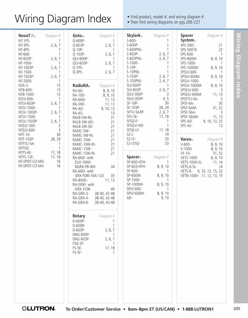
Skylark® Diagram #S-600- 1S-600P- 1S-600PNL- 1S-603P- 2, 6, 7S-603PNL- 2, 6, 7S-1000- 1S-10P- 1S-10PNL- 1S-103P- 2, 6, 7S-103PNL- 2, 6, 7SLV-600P- 1SLV-603P- 2, 6, 7SELV-300P- 3SELV-303P- 4, 5SF-10P- 30SF-103P- 28, 29SFTU-5A3P- 2, 6, 7SFS-5E- 17, 18SFSQ-F- 1SFSQ-F-HO- 1SFSQ-LF- 17, 18S2-L- 19S2-LF- 20S2-LFSQ- 20
Spacer® Diagram #SP-600-HTH- 1SP-603-HTH- 8, 9, 10SP-600- 1SP-600M- 8, 9, 10SP-1000- 1SP-1000M- 8, 9, 10SPLV-600- 1SPLV-600M- 8, 9, 10AD- 9, 10
Wirin
g D
iag
ram
Ind
ex
NovaTa® Diagram #NT-1PS- 1NT-3PS- 2, 6, 7NT-4PS- 7NT-600- 1NT-603P- 2, 6, 7NT-1000- 1NT-1003P- 2, 6, 7NT-1500- 1NT-1503P- 2, 6, 7NT-2000- 1NTA-2- 15NTB-600- 15NTB-1000- 15NTLV-600- 1NTLV-603P- 2, 6, 7NTLV-1000- 1NTLV-1003P- 2, 6, 7NTLV-1500- 1NTLV-1503P- 2, 6, 7NTELV-300- 3NTELV-600- 3NTF-10- 30NTF-103P- 28, 29NTFTU-5A- 1NTFSQ- 1NTFS-6E- 17, 18NTFS-12E- 17, 18NT-DPDT-CO-MO- 16NT-DPDT-CO-MA- 16
Qoto™ Diagram #Q-600P- 1Q-603P- 2, 6, 7Q-10P- 1Q-103P- 2, 6, 7QLV-600P- 1QLV-603P- 2, 6, 7Q-1PS- 1Q-3PS- 2, 6, 7
RadioRA® Diagram #RA-6D- 8, 9, 10RA-10D- 8, 9, 10RA-6ND- 11, 13RA-5NE- 11, 13RA-AD- 9, 10, 13RA-AS- 13RALB-5W-RL- 21RALB-5W-AO- 21RALB-2W-SD- 21RAMC-5W- 21RAMC-5W-RL- 21RAMC-10W- 21RAMC-10W-RL- 21RAMC-15W- 21RAMC-15W-RL- 21RA-6ND- with
ELVI-1000/NGRX-PB-WH 34
RA-6ND- with GRX-FDBI-16A-120 35
RA-8ANS- 11, 13RA-GRXI- with
GRX-3106 49RA-GRX-3- 38-40, 42-48RA-GRX-4- 38-40, 42-48RA-GRX-6- 38-40, 42-48
Rotary Diagram #D-600P- 1D-600R- 1D-603P- 2, 6, 7DNG-600P- 1DNG-603P- 2, 6, 7FSQ-2F- 1FS-5E- 17, 18FS-5F- 1
Spacer Diagram #System™
SPS-5WC- 21SPS-5WCR- 22SPS-600- 1SPS-600M- 8, 9, 10SPS-1000- 1SPS-1000M- 8, 9, 10SPSLV-600- 1SPSLV-600M- 8, 9, 10SPSLV-1000- 1SPSLV-1000M- 8, 9, 10SPSELV-600- 3SPSELV-600M- 11, 13SPSFTU-5A- 3SPSF-6A- 30SPSF-6AM- 31, 32SPSF-S6A- 3SPSF-S6AM- 11, 13SPS-AD- 9, 10, 13, 32SPS-AS- 13
Vareo® Diagram #V-600- 8, 9, 10V-1000- 8, 9, 10VF-10- 31, 32VETS-1000- 8, 9, 10VETS-1000-SL- 11, 14VETS-A-SL- 14VETS-R- 9, 10, 13, 15, 32VETN-1000- 11, 12, 13, 15
205To Order/Customer Service • 8am–8pm ET (US/CAN) • 1·888·LUTRON1
• Find product, model #, and wiring diagram #• Then find wiring diagrams on pgs.206-227Wiring Diagram Index

Ground Wire ConnectorMounting hardware, wire connectors,and instructions included with all products.
Wiring Diagrams
206 Technical Support • 24 Hours/7 Days • 1·800·523·9466 • www.lutron.com
Neutral
Black *
Dimmer, Switch, Fan Control
Black or Red *Hot
120VAC60Hz Feed
Lighting Load or FanGreen **
**or Brass screw terminal**or Green screw terminal
Wiring Diagram #1Single-pole wiring
Green ***
Neutral
Black *
Red **†
Red **Hot
120VAC60Hz Feed
Lighting Load or Fan
*** or Copper/Black screw terminal *** or Brass screw terminal *** or Green screw terminal † or Red/White stripe (cap off)
Dimmer, Switch, Fan Control
Wiring Diagram #2Single-pole wiring of 3-way control
Red or Yellow
Green White
Neutral
BlackDimmer, Switch
Hot
120VAC60Hz Feed
Lighting Load
Wiring Diagram #3Single-pole wiring with neutral wire connection
Neutral
Yellow *Hot
Green White120VAC60Hz Feed
Red **
Red **†
Lighting Load
Dimmer
*** or Copper/Black screw terminal *** or Brass/Gold screw terminal † or Red/White stripe (cap off)
Wiring Diagram #4Single-pole wiring of 3-way control with neutral wire connection
Control Load Side
Neutral
Yellow *Hot
Green White120VAC60Hz Feed
*
Red **
Red **†
***
Lighting Load
3-WaySwitch Dimmer
*** or Copper/Black screw terminal *** or Brass/Gold screw terminal † or Red/White stripe (cap off)
Wiring Diagram #53-way wiring with neutral wire connection
Note:1. Only one dimmer can be used per 3-way circuit.
Follow this diagram when incorporating a 3-way on/off switch with the dimmer. The 3-way switch must be wired on line side of the dimmer.

Ground Wire ConnectorMounting hardware, wire connectors,and instructions included with all products.
207To Order/Customer Service • 8am–8pm ET (US/CAN) • 1·888·LUTRON1
Wirin
g D
iag
ram
s
Wiring Diagrams
Control Line Side
Control Load Side
Black ** Red * *
Red *† *
*
*
** **
**
Red *†*
Neutral
Hot
Green *** ***120VAC60Hz Feed
Dimmer, Switch, Fan Control
4-WaySwitch
Lighting Load or Fan
3-WaySwitch
Neutral
Hot
Green ***120VAC60Hz Feed
** *
*
*
**
** Black **Red *
4-WaySwitch
Lighting Load or Fan
3-WaySwitch
Dimmer, Switch, Fan Control
OR
*** or Copper/Black screw terminal *** or Brass/Gold screw terminal *** or Green screw terminal † or Red/White stripe
Wiring Diagram #74-way wiring
Control Line Side 3-Way
SwitchDimmer, Switch, Fan Control
Dimmer, Switch, Fan Control
Lighting Load or Fan
Neutral
Red *
Red *†
Green *** *** *** Green ***
Black **Hot
120VAC60Hz Feed
3-WaySwitch
Lighting Load or Fan
Neutral
Red *
Red *†
Black **Hot
120VAC60Hz Feed
OR
Control Load Side
* ** **
*
*
*
*** or Brass/Gold screw terminal *** or Copper/Black screw terminal *** or Green screw terminal † or Red/White stripe
Wiring Diagram #63-way wiring
Wiring Diagrams
208 Technical Support • 24 Hours/7 Days • 1·800·523·9466 • www.lutron.com
Control Line Side
Neutral
Red
Blue
Control Accessory Accessory AccessoryBlack BlackHot
Up to Nine Total Accessories
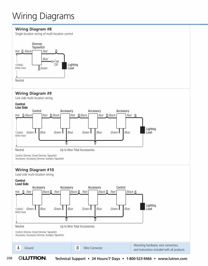
Control: Dimmer, Smart Dimmer, TapswitchAccessory: Accessory Dimmer, Auxiliary Tapswitch
120VAC60Hz Feed
Green Green Green GreenBlue
Red Black
Blue
Red Black
BlueLighting Load
Red
Wiring Diagram #9Line side multi-location wiring
Control Load Side
Neutral
Black
Blue
Accessory Accessory Accessory ControlRed RedHot
Up to Nine Total Accessories
Control: Dimmer, Smart Dimmer, TapswitchAccessory: Accessory Dimmer, Auxiliary Tapswitch
120VAC60Hz Feed
Green Green Green GreenBlue
Black Red
Blue
Black Red
BlueLighting Load
Black
Wiring Diagram #10Load side multi-location wiring
Green
Dimmer,Tapswitch
Black Red
BlueCap Off Lighting
Load
Neutral
Hot
120VAC60Hz Feed
Wiring Diagram #8Single-location wiring of multi-location control
Ground Wire ConnectorMounting hardware, wire connectors,and instructions included with all products.

Ground Wire ConnectorMounting hardware, wire connectors,and instructions included with all products.
209To Order/Customer Service • 8am–8pm ET (US/CAN) • 1·888·LUTRON1
Wirin
g D
iag
ram
s
Wiring Diagrams
Control Line Side
Lighting Load
Neutral
Red
Blue
TapswitchAuxiliary Tapswitch
Black BlackHot
120VAC60Hz Feed
Green Green
Red
Blue
Up to Nine Total Auxiliary Tapswitches
White
Wiring Diagram #12Line side multi-location wiring with neutral wire connection
Neutral
Green
Black
Control
Red
Blue
Hot
120/277VAC60Hz Feed
Control: Dimmer, Smart Dimmer, Electronic Switch, Tapswitch
Lighting Load or FanWhite
Cap Off
Wiring Diagram #11Single-pole wiring of multi-location control with neutral wire connection
Control Load Side
Neutral
BlackBlack Red RedHot
120/277VAC60Hz Feed
Green Green
Black
Blue Blue BlueGreen
Lighting Load or FanWhite
Red Black
GreenBlue
Up to Nine Accessories
Accessory Accessory Accessory ControlRed or Yellow
Control: Dimmer, Smart Dimmer, Electronic Switch, TapswitchAccessory: Accessory Dimmer, Accessory Switch, Auxiliary Tapswitch
Wiring Diagram #13Multi-location switch wiring with neutral wire connection

Ground Wire ConnectorMounting hardware, wire connectors,and instructions included with all products.
Wiring Diagrams
210 Technical Support • 24 Hours/7 Days • 1·800·523·9466 • www.lutron.com
Neutral
Red
Blue
Lighting Load
Lighting Load
BaseDimmer
AuxiliaryDimmer
BaseDimmer
AuxiliaryDimmer
Red
Orange
BlackHot
120VAC60Hz Feed
Neutral
Red
Blue
Red
Orange
Green GreenGreen Green
BlackBlack BlackHot
120VAC60Hz Feed
Base Control Line Side
Base Control Load Side
OR
Wiring Diagram #15Omnislide™ wiring
Control Line Side
Control Load Side
Lighting Load or Fan
Neutral
Red Red
Blue
VETS-1000-SL
VETS-1000-SL
VETS-A-SL VETS-A-SL
VETS-A-SL VETS-A-SL
Orange
Black
White
Black BlackHot
120VAC60Hz Feed Green Green
Red
Blue BlueOrange
Green
OR
Lighting Load or Fan
Neutral
Red Black
BlueOrange
Red
White
Black BlackHot
120VAC60Hz Feed Green Green
Red
BlueBlue Orange
Green
Up to Four Total VETS-A-SL Units
Up to Four Total VETS-A-SL Units
Wiring Diagram #14Vareo® switch wiring with neutral wire connection

Ground Wire ConnectorMounting hardware, wire connectors,and instructions included with all products.
211To Order/Customer Service • 8am–8pm ET (US/CAN) • 1·888·LUTRON1
Wirin
g D
iag
ram
s
Wiring DiagramsWiring Diagram #16AC motor wiring of double-pole, double-throw switch
A1
Rear View of NT-DPDT-CO-MO-, NT-DPDT-CO-MA-
A2L1
L2B1 B2
Motor Motor
Hot
Neutral
Hot
Neutral
Lower
Raise
Lower
Raise
120VAC60Hz Feed
120VAC60Hz Feed
Hot
FanControl
Black Red to Fan
Yellow to Light *Fan
Incandescent Load
Green
Neutral
120VAC60Hz Feed
* Switched full voltage only
Wiring Diagram #18Single-pole wiring, fan and light
Hot
Fan Control
Black Red
Yellow (Cap off) *FanGreen
Neutral
120VAC60Hz Feed
* Switched full voltage only
Wiring Diagram #17Single-pole wiring, fan only
Hot
Dual LightControl
Black
Yellow
Red
Lighting Load
Lighting LoadGreen
Neutral
120VAC60Hz Feed
Wiring Diagram #19Single-pole wiring, dual light control
Hot
DualControl
Black Yellow to Fan
Red to Light
FanLighting Load
Green
Neutral
120VAC60Hz Feed
Wiring Diagram #20Single-pole wiring, dual fan/light control

Ground Wire ConnectorMounting hardware, wire connectors,and instructions included with all products.
Wiring Diagrams
212 Technical Support • 24 Hours/7 Days • 1·800·523·9466 • www.lutron.com
Wiring Diagram #22Remote-mounted master control wiring with infrared blaster
> > >< < <
Green
Neutral
Hot
120VAC 60Hz Feed
Black Red/White Stripe
White
Red/White StripeTraveler
Infrared Blaster emits signal that travels up to 2 dimmers in either direction.
Traveler
Traveler
Traveler
Red/White Stripe Red/White Stripe
Red/White Stripe
Red/White Stripe
Master Control
Wallbox
Wall-Mounted Master Control
Wallbox
Spacer System™ Infrared Blaster
Rear View of 5 Spacer System Dimmers Ganged Together
Spacer System Dimmer
Wallbox
Spacer System Infrared Blaster (Optional)
Spacer System Dimmer
Green
MasterControl
White
BlackHot
120VAC60Hz Feed
Neutral
> > > > > > > >< <
SPS-5WC- emits signal that travels up to 4 dimmers in either direction.
Rear View of Spacer System Dimmers and SPS-5WC- Ganged Together
Wiring Diagram #21Wall-mounted master control wiring

Ground Wire ConnectorMounting hardware, wire connectors,and instructions included with all products.
213To Order/Customer Service • 8am–8pm ET (US/CAN) • 1·888·LUTRON1
Wirin
g D
iag
ram
s
Wiring Diagrams
Hot
Load Hot
Neutral
Load Neutral
Black
White
Green Green Green
Neutral
Hot
Receptacle (15A Shown) Not Protected
GFCI Receptacle (15A Shown) Protected
Receptacle (15A Shown) Protected
120VAC60Hz Feed Nickel
Plated Screws
BrassScrews
Wiring Diagram #27GFCI receptacle wiring
75-OhmCable 75-Ohm
Cable
Cable Jack
Wiring Diagram #23Cable jack wiring
6-ConductorTelephone Jack*
WireColor
Jack Position
1 White2 Black3 Red4 Green5 Yellow6 Blue
* accepts most 4-conductor jacks
Wiring Diagram #24Telephone jack wiring, 6-conductor
8-ConductorTelephone Jack*
WireColor
Jack Position
1 Blue2 Orange3 Black4 Red5 Green6 Yellow7 Brown8 White
* accepts most 4- or 6-conductor jacks
Wiring Diagram #25Telephone jack wiring, 8-conductor
Neutral
Black
Receptacle (15A Shown)
WhiteHot
120VAC60Hz Feed
Nickel Plated Screws
BrassScrews
**for split circuit wiring, break off tab on brass side only
Green Screw Building Ground (to metal box) or Isolated Ground
*
Wiring Diagram #26Receptacle wiring
Ground Wire ConnectorMounting hardware, wire connectors,and instructions included with all products.
Wiring Diagrams
214 Technical Support • 24 Hours/7 Days • 1·800·523·9466 • www.lutron.com
Green
120VAC60Hz Feed
To Additional Ballasts
Dimmer
Orange or Brown **
White *
BlackBlack
Orange or Brown **
White *
Yellow or Orange
Black
Blue RedHot
Neutral
White
Violet or Blue
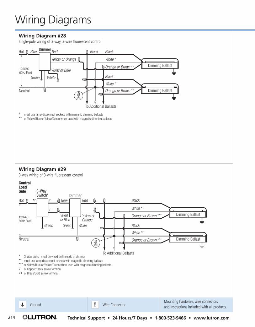
*** must use lamp disconnect sockets with magnetic dimming ballasts *** or Yellow/Blue or Yellow/Green when used with magnetic dimming ballasts
Dimming Ballast
Dimming Ballast
Wiring Diagram #28Single-pole wiring of 3-way, 3-wire fluorescent control
Control Load Side
* 3-Way switch must be wired on line side of dimmer*** must use lamp disconnect sockets with magnetic dimming ballasts*** or Yellow/Blue or Yellow/Green when used with magnetic dimming ballasts † † or Copper/Black screw terminal † † or Brass/Gold screw terminal
GreenGreen
120VAC60Hz Feed
To Additional Ballasts
Dimmer3-Way Switch*
Orange or Brown ***
White **
Black
Orange or Brown ***
White **
Black
RedHot
Neutral
White
Violet or Blue
Yellow or Orange
Blue† † †
†
Dimming Ballast
Dimming Ballast
Wiring Diagram #293-way wiring of 3-wire fluorescent control

Ground Wire ConnectorMounting hardware, wire connectors,and instructions included with all products.
215To Order/Customer Service • 8am–8pm ET (US/CAN) • 1·888·LUTRON1
Wirin
g D
iag
ram
s
Wiring Diagrams
DimmerAccessoryAccessory
Up to Nine Total Accessories
To Additional Ballasts
Black
White
Orange
Black
White
OrangeOrange
Neutral
Accessory: Accessory Dimmer, Auxiliary Tapswitch
Red Red
Blue
Black
White
Black Black
Hot
120VAC 60Hz Feed
Green Green Green
Red
BlueBlue
Control Load Side
Dimming Ballast
Dimming Ballast
Wiring Diagram #32Multi-location wiring of 3-wire fluorescent control
Green
Red
White **
White **
Orange or Brown *
Orange or Brown *
*** or Yellow/Blue or Yellow/Green when used with magnetic dimming ballasts *** must use lamp disconnect sockets with magnetic dimming ballasts
Black
Black
To Additional Ballasts
Neutral
Yellow or Orange
Dimmer
BlackHot
White120VAC60Hz Feed
Dimming Ballast
Dimming Ballast
Wiring Diagram #30Single-pole wiring of 3-wire fluorescent control
Green
Neutral
Hot
120VAC 60Hz Feed
Black Orange
Blue
Red
White
Black
White
Orange
Black
White
Orange
To Additional Ballasts
Dimmer
Dimming Ballast
Dimming Ballast
Wiring Diagram #31Single-pole wiring of multi-location 3-wire fluorescent control
Ground Wire ConnectorMounting hardware, wire connectors,and instructions included with all products.
Wiring Diagrams
216 Technical Support • 24 Hours/7 Days • 1·800·523·9466 • www.lutron.com
Green
Brown *
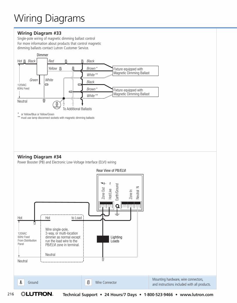
** or Yellow/Blue or Yellow/Green** must use lamp disconnect sockets with magnetic dimming ballasts
White **
Black
Brown *Yellow
White **
BlackRed
To Additional Ballasts
Neutral
Dimmer
BlackHot
120VAC60Hz Feed
Fixture equipped withMagnetic Dimming Ballast
Fixture equipped withMagnetic Dimming Ballast
White
Wiring Diagram #33Single-pole wiring of magnetic dimming ballast controlFor more information about products that control magnetic dimming ballasts contact Lutron Customer Service.
LightingLoads
Neut
ral
N
Zone
In
Earth
/Gro
und
Hot/L
ive
Zone
Out
Neutral
Hot Hot
Neutral
to Load
Rear View of PB/ELVI
120VAC 60Hz Feed From Distribution Panel
Wire single-pole, 3-way, or multi-location dimmer as normal except run the load wire to the PB/ELVI zone in terminal.
Wiring Diagram #34Power Booster (PB) and Electronic Low-Voltage Interface (ELVI) wiring

Ground Wire ConnectorMounting hardware, wire connectors,and instructions included with all products.
217To Order/Customer Service • 8am–8pm ET (US/CAN) • 1·888·LUTRON1
Wirin
g D
iag
ram
s
Wiring Diagrams
***
or Y
ello
w/B
lue
or Y
ello
w/G
reen
whe
n us
ed w
ith m
agne
tic d
imm
ing
balla
sts
***
mus
t use
lam
p di
scon
nect
soc
kets
with
mag
netic
dim
min
g ba
llast
s
Neutral N
Zone In
SW Hot/Live
Earth/Ground
Hot/Live
Zone OutNe
utra
l
Hot
Hot
Neut
ral
to L
oad
Rear
Vie
w o
f FDB
I
120V
AC
60Hz
Fee
d Fr
om D
istri
butio
n
Pane
l
Wire
sin
gle-
pole
, 3-
way
, or m
ulti-
loca
tion
dim
mer
as
norm
al e
xcep
t ru
n th
e lo
ad w
ire to
the
FD
BI z
one
in te
rmin
al.
Whi
te **
Whi
te **
Blac
k
Oran
ge o
r Bro
wn
*
Oran
ge o
r Bro
wn
*
Blac
k
To A
dditi
onal
Bal
last
s
Dim
min
g Ba
llast
Dim
min
g Ba
llast
Wiring Diagram #35Fluorescent Dimming Ballast Interface (FDBI) interface wiring

Ground Wire ConnectorMounting hardware, wire connectors,and instructions included with all products.
Wiring Diagrams
218 Technical Support • 24 Hours/7 Days • 1·800·523·9466 • www.lutron.com
Neutral
Hot/Live
Dimmed Hot
N
Control Circuit Terminals
N H H DH 1 2 3
Hot/LiveBlack
Black
Hi-Power 2·4·6
Single-Pole Dimmer
120VAC 60Hz Feed From Distribution Panel To additional HP 2·4·6 Dimming
Modules (Five Maximum)
Wiring Diagram #36Single-pole wiring to a Hi-Power 2·4·6™ dimming module
Neutral
Hot/Live
N
Control Circuit Terminals
N H H DH 1 2 3
Dimmed Hot
Hot/LiveRedBlack
Red or Red/White
Hi-Power 2·4·6
Dimmer
120VAC 60Hz Feed From Distribution Panel To additional HP 2·4·6 Dimming
Modules (Five Maximum)
3-Way Switch
Wiring Diagram #373-way wiring to a Hi-Power 2·4·6 dimming module
Grou
ndW
ire C
onne
ctor
Zone
1Zo
ne 3
Zone
5
Neut
ral
Zone
2Zo
ne 4
CU W
ire O
nly
Zone
6
Hot/L
iveCL
ASS
2 SS
A1
23
4
Neut
ral
Earth
/Gro
und
from
Dist
ribut
ion
Pane
l
Dist
ribut
ion
Pane
l
Hot/L
ive
Load
2
Hot/L
ive
2 #1
2 AW
G
Load
52
#12
AWG
Neut
ral
(2.5
mm
2 )(2
.5m
m2 )
(2.5
mm
2 )
Load
42
#12
AWG
2 #1
2 AW
GLo
ad 6
Load
32
#12
AWG
Rear
Vie
w o
f GRA
FIK
Eye
Cont
rol U
nit (
GRX-
3106
sho
wn)
USA
Clas
s 2
IEC
PELV
2 #1
2 AW
G
2 #1
2 AW
GLo
ad 1
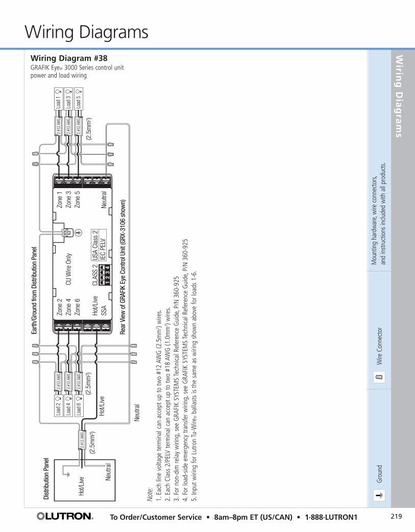
Wiring Diagram #38GRAFIK Eye® 3000 Series control unitpower and load wiring
Note
:1.
Each
line
vol
tage
term
inal
can
acc
ept u
p to
two
#12
AWG
(2.5
mm
2 ) wire
s.2.
Each
Cla
ss 2
/PEL
V te
rmin
al c
an a
ccep
t up
to tw
o #1
8 AW
G (1
.0m
m2 ) w
ires.
3.Fo
r non
-dim
rela
y w
iring
,see
GRA
FIK
SYST
EMS
Tech
nica
l Ref
eren
ce G
uide
,P/N
360
-925
4.Fo
r loa
d-sid
e em
erge
ncy
trans
fer w
iring
,see
GRA
FIK
SYST
EMS
Tech
nica
l Ref
eren
ce G
uide
,P/N
360
-925
5.In
put w
iring
for L
utro
n Tu
-Wire
®ba
llast
s is
the
sam
e as
wiri
ng s
how
n ab
ove
for l
oads
1-6
.
219To Order/Customer Service • 8am–8pm ET (US/CAN) • 1·888·LUTRON1
Wirin
g D
iag
ram
s
Wiring Diagrams
Mou
ntin
g ha
rdw
are,
wire
con
nect
ors,
and
inst
ruct
ions
inclu
ded
with
all
prod
ucts.

Grou
ndW
ire C
onne
ctor
Mou
ntin
g ha
rdw
are,
wire
con
nect
ors,
and
inst
ruct
ions
inclu
ded
with
all
prod
ucts.
Wiring Diagrams
220 Technical Support • 24 Hours/7 Days • 1·800·523·9466 • www.lutron.com
Zone
1Zo
ne 3
Zone
5
Neut
ral
Zone
2Zo
ne 4
CU W
ire O
nly
Zone
6
Hot/L
iveCL
ASS
2 SS
AUS
A Cl
ass
2IE
C PE
LV
Data
Lin
k3:
MUX
4: M
UX
Wal
lstat
ion
Wal
lstat
ion
Wal
lstat
ion
Clas
s 2/
PELV
Cont
rol W
iring
1: C
omm
on2:
12V
DC
Lutro
n Ca
ble,
GR
X-CB
L-34
6S
(non
-ple
num
)
12
34
56
12
34
56
12
34
56
4 3 2 1
4 3 2 1
Hot/L
ive
Earth
/Gro
und
from
Dist
ribut
ion
Pane
l
Blac
kBl
ue
NTGR
X-1S
(10
Max
imum
)
4 3 2 1
Rear
Vie
w o
f GRA
FIK
Eye
Cont
rol U
nit (
GRX-
3106
sho
wn)
Line
Vo
ltage
Wiri
ng
Dist
ribut
ion
Pane
l
Hot/
Live
2 #1
2 AW
G
Neut
ral
(2.5
mm
2 )
12
34
12
34
Wiring Diagram #39GRAFIK Eye® 3000 Series control unit to wallstation wiring
Note
:1.
For o
ther
pos
sible
NTG
RX-1
S w
iring
con
figur
atio
ns,s
ee G
RAFI
K Ey
e Ap
plica
tion
Not
es a
vaila
ble
at w
ww
.lutro
n.co
m.
2.Th
e N
TGRX
-1S
is fo
r use
with
3-,
4-,a
nd 6
-zon
e co
ntro
l uni
ts o
nly.
3.Ea
ch c
ontro
l uni
t can
pow
er u
p to
thre
e Cl
ass
2/PE
LV w
allst
atio
ns/c
ontro
l int
erfa
ces.
If m
ore
than
thre
e ne
ed to
be
conn
ecte
d to
one
con
trol u
nit,
inst
all a
n ex
tern
al 1
2VDC
pow
er s
uppl
y as
sho
wn
in W
iring
Dia
gram
#43
.4.
Clas
s 2/
PELV
non
-ple
num
cab
le is
ava
ilabl
e fro
m L
utro
n,or
der G
RX-C
BL-3
46S-
500
(non
-ple
num
rate
d ca
ble)
or G
RX-P
CBL-
346S
-500
(ple
num
-rate
d ca
ble)
.

Grou
ndW
ire C
onne
ctor
221To Order/Customer Service • 8am–8pm ET (US/CAN) • 1·888·LUTRON1
Wirin
g D
iag
ram
s
Wiring DiagramsRe
ar V
iew
of G
RAFI
K Ey
e Co
ntro
l Uni
t (GR
X-31
06 s
how
n) Zone
1Zo
ne 3
Zone
5
Neut
ral
Zone
2Zo
ne 4
CU W
ire O
nly
Zone
6
Hot/L
iveCL
ASS
2 SS
AUS
A Cl
ass
2IE
C PE
LV
Rear
Vie
w o
f GRA
FIK
Eye
Cont
rol U
nit (
GRX-
3106
sho
wn) Zone
1Zo
ne 3
Zone
5
Neut
ral
Zone
2Zo
ne 4
CU W
ire O
nly
Zone
6
Hot/L
iveCL
ASS
2 SS
AUS
A Cl
ass
2IE
C PE
LV1
23
41
23
41
23
41
23
4
Zone
1Zo
ne 3
Neut
ral
Zone
2Zo
ne 4
CU W
ire O
nly
Hot/L
iveCL
ASS
2 SS
A1
23
4
Earth
/Gro
und
from
Dist
ribut
ion
Pane
lDi
strib
utio
n Pa
nel
Hot/
Live
Load
2
Hot/L
ive
Neut
ral
2 #1
2 AW
G
Neut
ral
(2.5
mm
2 )
(2.5
mm
2 )(2
.5m
m2 )
Load
42
#12
AWG
Load
32
#12
AWG
Rear
Vie
w o
f GRA
FIK
Eye
Cont
rol U
nit (
GRX-
3106
sho
wn)
USA
Clas
s 2
IEC
PELV
2 #1
2 AW
GLo
ad 1
Blac
kBl
ue
NTGR
X-1S
(10
Max
imum
)
2 #1
2 AW
G
Wiring Diagram #40GRAFIK Eye® 3000 Series control unitto control unit wiring
Wiring Diagram #41GRAFIK Eye 2000 Series control unit wiring and NTGRX-1S- wallstation wiring
Note
:1.
Each
con
trol u
nit h
as it
s ow
n po
wer
sup
ply.
2.Do
not
con
nect
term
inal
No.
2 w
hen
wiri
ng b
etw
een
GRA
FIK
Eye
3000
Ser
ies
cont
rol u
nits
.3.
Clas
s 2/
PELV
cab
le is
ava
ilabl
e fro
m L
utro
n,or
der G
RX-C
BL-3
46S-
500
(non
-ple
num
rate
d ca
ble)
or G
RX-P
CBL-
346S
-500
(ple
num
-rate
d ca
ble)
.
Note
:1.
The
NTG
RX-1
S- is
for u
se
with
3-z
one
and
4-zo
ne
cont
rol u
nits
onl
y.
Mou
ntin
g ha
rdw
are,
wire
con
nect
ors,
and
inst
ruct
ions
inclu
ded
with
all
prod
ucts.
Grou
ndW
ire C
onne
ctor
Mou
ntin
g ha
rdw
are,
wire
con
nect
ors,
and
inst
ruct
ions
inclu
ded
with
all
prod
ucts.
Wiring Diagrams
222 Technical Support • 24 Hours/7 Days • 1·800·523·9466 • www.lutron.com
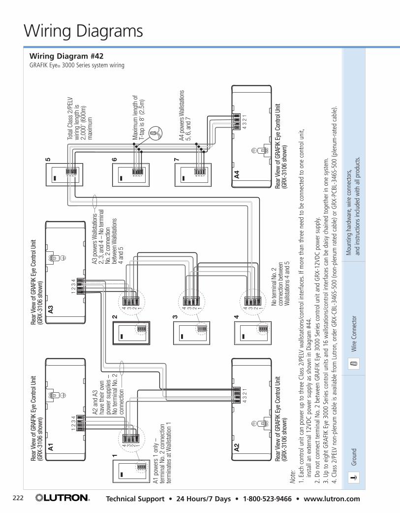
A1
12 3 4
5 6 7
A3
A2
A4
A2 a
nd A
3 ha
ve th
eir o
wn
pow
er s
uppl
ies
–No
term
inal
No.
2
conn
ectio
n
Tota
l Cla
ss 2
/PEL
Vw
iring
leng
th is
2,00
0’ (6
00m
) m
axim
um
Max
imum
leng
th o
fT-
tap
is 8
’ (2.
5m)
A1 p
ower
s 1
only
– te
rmin
al N
o. 2
con
nect
ion
term
inat
es a
t Wal
lsta
tion
1
A4 p
ower
s Wall
stat
ions
5, 6
, and
7
A3 p
ower
s Wall
stat
ions
2, 3
, and
4 –
No
term
inal
No
. 2 c
onne
ction
be
twee
n W
allst
ation
s4
and
5
4 3 2 1
12
34
43
21
12
34
43
21
4 3 2 1
4 3 2 1 4 3 2 14 3 2 1
4 3 2 1
4 3 2 1 4 3 2 1
4 3 2 1 4 3 2 1 4 3 2 1
Rear
Vie
w o
f GRA
FIK
Eye
Cont
rol U
nit
(GRX
-310
6 sh
own)
Rear
Vie
w o
f GRA
FIK
Eye
Cont
rol U
nit
(GRX
-310
6 sh
own)
Rear
Vie
w o
f GRA
FIK
Eye
Cont
rol U
nit
(GRX
-310
6 sh
own)
Rear
Vie
w o
f GRA
FIK
Eye
Cont
rol U
nit
(GRX
-310
6 sh
own)
No te
rmin
al No
. 2
conn
ectio
n be
twee
n W
allst
ation
s 4
and
5No
te:
1.Ea
ch c
ontro
l uni
t can
pow
er u
p to
thre
e Cl
ass
2/PE
LV w
allst
atio
ns/c
ontro
l int
erfa
ces.
If m
ore
than
thre
e ne
ed to
be
conn
ecte
d to
one
con
trol u
nit,
inst
all a
n ex
tern
al 1
2VDC
pow
er s
uppl
y as
sho
wn
in D
iagr
am #
44.
2.Do
not
con
nect
term
inal
No.
2 be
twee
n G
RAFI
K Ey
e 30
00 S
erie
s co
ntro
l uni
t and
GRX
-12V
DC p
ower
sup
ply.
3.Up
to e
ight
GRA
FIK
Eye
3000
Ser
ies
cont
rol u
nits
and
16
wal
lstat
ions
/con
trol i
nter
face
s ca
n be
dai
sy c
hain
ed to
geth
er in
one
sys
tem
.4.
Clas
s 2/
PELV
non
-ple
num
cab
le is
ava
ilabl
e fro
m L
utro
n,or
der G
RX-C
BL-3
46S-
500
(non
-ple
num
rate
d ca
ble)
or G
RX-P
CBL-
346S
-500
(ple
num
-rate
d ca
ble)
.
Wiring Diagram #42GRAFIK Eye® 3000 Series system wiring

Grou
ndW
ire C
onne
ctor
223To Order/Customer Service • 8am–8pm ET (US/CAN) • 1·888·LUTRON1
Wirin
g D
iag
ram
s
Wiring DiagramsWiring Diagram #43GRAFIK Eye® 3000 SeriesGRX-12VDC power-supply wiring
Mou
ntin
g ha
rdw
are,
wire
con
nect
ors,
and
inst
ruct
ions
inclu
ded
with
all
prod
ucts.
Rear
Vie
w o
f GRA
FIK
Eye
Cont
rol U
nit (
GRX-
3106
sho
wn)
Zone
1Zo
ne 3
Zone
5
Neut
ral
Zone
2Zo
ne 4
CU W
ire O
nly
Zone
6
Hot/L
iveCL
ASS
2 SS
AUS
A Cl
ass
2IE
C PE
LV
12
34
56
Wal
lstat
ion
12
34
56
Wal
lstat
ion
12
34
56
12
34
56
One
twis
ted
pair
#18
AWG
(1.0
mm
2 )
Two
twis
ted
pair
#18
AWG
(1.0
mm
2 )
One
#18
AWG
(1.0
mm
2 )Co
mm
onW
allst
atio
ns/C
ontro
l Int
erfa
ces
(16
Max
imum
)(+
) 12V
DC
GRX-
12VD
C
To P
ower
Sou
rce
Wal
lstat
ion
Wal
lstat
ion
4 3 2 1
Lutro
n ca
ble,
GRX-
CBL-
346S
(non
-ple
num
)
4 3 2 1
4 3 2 1
12
34
12
34
4 3 2 1
Note
:1.
Do n
ot c
onne
ct te
rmin
al N
o.2
betw
een
GRA
FIK
Eye
3000
Ser
ies
cont
rol u
nit a
nd G
RX-1
2VDC
pow
er s
uppl
y.2.
Clas
s 2/
PELV
non
-ple
num
cab
le is
ava
ilabl
e fro
m L
utro
n,or
der G
RX-C
BL-3
46S-
500
(non
-ple
num
rate
d ca
ble)
or G
RX-P
CBL-
346S
-500
(ple
num
-rate
d ca
ble)
.
Ground Wire ConnectorMounting hardware, wire connectors,and instructions included with all products.
Wiring Diagrams
224 Technical Support • 24 Hours/7 Days • 1·800·523·9466 • www.lutron.com
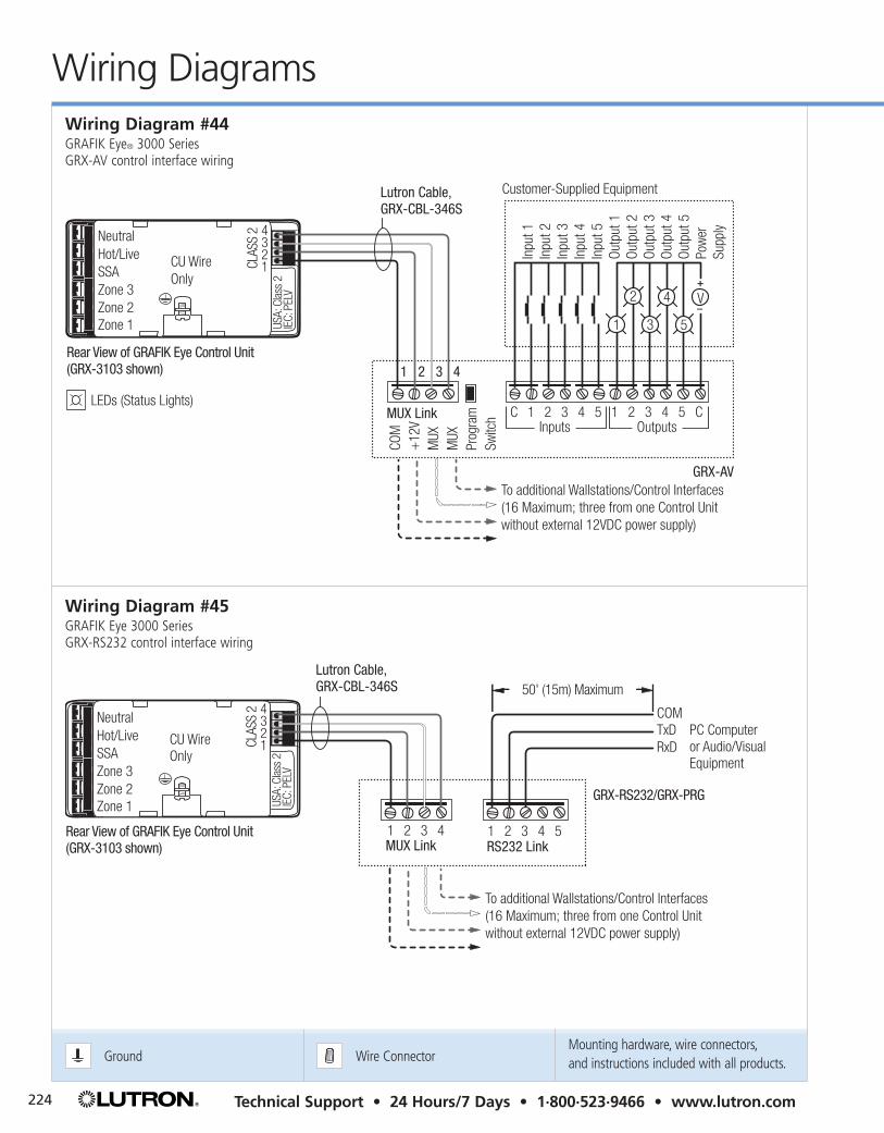
Wiring Diagram #44GRAFIK Eye® 3000 SeriesGRX-AV control interface wiring
Wiring Diagram #45GRAFIK Eye 3000 SeriesGRX-RS232 control interface wiring
CLAS
S 2 4
321
Neutral
SSAZone 3Zone 2Zone 1
Hot/Live CU Wire Only
Inputs OutputsMUX Link
Customer-Supplied Equipment
C 1 2 3 4 5 1 2 3 4 5 C
+
–V
1
2
3 5
4
Inpu
t 1In
put 2
Inpu
t 3In
put 4
Inpu
t 5Ou
tput
1Ou
tput
2Ou
tput
3Ou
tput
4Ou
tput
5Po
wer
Supp
ly
COM
+12
VM
UXM
UXPr
ogra
mSw
itch
Rear View of GRAFIK Eye Control Unit (GRX-3103 shown)
GRX-AVTo additional Wallstations/Control Interfaces(16 Maximum; three from one Control Unit without external 12VDC power supply)
USA:
Cla
ss 2
IEC:
PEL
V
Lutron Cable, GRX-CBL-346S
1 2 3 4
LEDs (Status Lights)
RS232 Link
GRX-RS232/GRX-PRG
1 2 3 4 5
COM
50' (15m) Maximum
RxDPC Computer or Audio/Visual Equipment
TxD
Rear View of GRAFIK Eye Control Unit (GRX-3103 shown) MUX Link
USA:
Cla
ss 2
IEC:
PEL
V
Lutron Cable, GRX-CBL-346S
CLAS
S 2 4
321
Neutral
SSAZone 3Zone 2Zone 1
Hot/Live CU Wire Only
1 2 3 4
To additional Wallstations/Control Interfaces(16 Maximum; three from one Control Unit without external 12VDC power supply)

Ground Wire ConnectorMounting hardware, wire connectors,and instructions included with all products.
225To Order/Customer Service • 8am–8pm ET (US/CAN) • 1·888·LUTRON1
Wirin
g D
iag
ram
s
Wiring Diagrams
Note:1. Control circuit feed is shown coming from the GRAFIK Eye control unit feed. The load on the dimmer for each Hi-Power
2·4·6 module connected is 20W/VA. Hi-Power 2·4·6 has a special active load which will meet the minimum load requirements for any Lutron dimmer. If the circuit does not have sufficient capacity to support the load of the module(s),the Hi-Power 2·4·6 control circuit feed can be supplied from any 120VAC circuit with sufficient capacity as long as it is on the same phase as the GRAFIK Eye control unit. Do not use Hi-Power 2·4·6 with generator-supplied power.
2. Load type should be set as incandescent on the GRAFIK Eye control unit.3. Dimmed hot is shown connected to Zone 1 in the diagram, but can be connected to any zone on the control unit.4. For GRAFIK Eye 3000 Series control units, refer to GRAFIK Eye 3000 Instruction Sheet (P/N 032-083) for the
remainder of control unit wiring.5. Refer to Hi-Power 2·4·6 Instruction Sheet (P/N 030-452) for the remainder of Hi-Power 2·4·6 wiring.
CLAS
S 2 4
321
Neutral
SSAZone 3Zone 2Zone 1
Hot/Live CU Wire Only
Rear View of GRAFIK Eye Control Unit 2, 4
(GRX-3103 shown)US
A: C
lass
2IE
C: P
ELV
Neutral
Neutral
Hot/Live
Dimmed Hot
Control Circuit Feed: 1
Hot
To additional loads
N
Control Circuit Terminals
N H H DH 1 2 3
Hi-Power 2·4·6 5
120VAC Feed fromDistributionPanel
To additional HP 2·4·6Modules (Five Maximum)
3
Wiring Diagram #46GRAFIK Eye® 3000 Series control unit to Hi-Power 2·4·6™ wiring
Grou
ndW
ire C
onne
ctor
Mou
ntin
g ha
rdw
are,
wire
con
nect
ors,
and
inst
ruct
ions
inclu
ded
with
all
prod
ucts.
Wiring Diagrams
226 Technical Support • 24 Hours/7 Days • 1·800·523·9466 • www.lutron.com
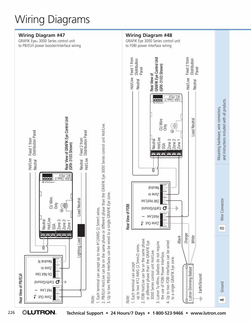
Wiring Diagram #48GRAFIK Eye 3000 Series control unit to FDBI power interface wiring
Load
Neu
tral
Neut
ral
Hot/L
iveFe
ed 1
from
Dist
ribut
ion
Pane
l
Feed
2 fr
omDi
strib
utio
nPa
nel
Neut
ral
Hot/L
ive
Neutral
Zone In
SW Hot/Live
Earth/Ground
Hot/Live
Zone Out
Oran
ge
Whi
te
Blac
k
Lutro
n Di
mm
ing
Balla
st
Earth
/Gro
und
Rear
Vie
w o
f FDB
I
Rear
Vie
w o
f GR
AFIK
Eye
Con
trol U
nit
(GRX
-310
3 Sh
own)
USA: Class 2IEC: PELV
4 3 2 1
Neut
ral
SSA
Zone
3Zo
ne 2
Zone
1
Hot/L
iveCU
Wire
Only
Wiring Diagram #47GRAFIK Eye® 3000 Series control unit to PB/ELVI power booster/interface wiring
4 3 2 1
Neut
ral
SSA
Zone
3Zo
ne 2
Zone
1
Hot/L
iveCU
Wire
On
ly
USA: Class 2IEC: PELV
Neutral N
Zone In
Do Not Use
Earth/Ground
Hot Live
Zone OutRe
ar V
iew
of P
B/EL
VI
Rear
Vie
w o
f GRA
FIK
Eye
Cont
rol U
nit
(GRX
-310
3 Sh
own)
Load
Neu
tral
Ligh
ting
Load
Neut
ral
Hot/L
ive
Neut
ral
Hot/L
ive
Feed
1 fr
omDi
strib
utio
n Pa
nel
Feed
2 fr
omDi
strib
utio
n Pa
nel
Note
:1.
Each
term
inal
can
acc
ept u
p to
two
#12A
WG
(2.5
mm
2 ) w
ires.
2.PB
/ELV
I Hot
/Liv
e ca
n be
on
the
sam
e ph
ase
or d
iffer
ent p
hase
than
the
GRA
FIK
Eye
3000
Ser
ies
cont
rol u
nit H
ot/L
ive.
3.Up
to tw
o PB
/ELV
I int
erfa
ces
can
be w
ired
to a
sin
gle
GRA
FIK
Eye
zone
.
Note
:1.
Each
term
inal
can
acc
ept
up to
two
#12
AWG
(2.5
mm
2) w
ires.
2.FD
BI H
ot/L
ive
can
be o
n th
e sa
me
phas
eor
diff
eren
t pha
se th
an th
e G
RAFI
K Ey
e30
00 S
erie
s co
ntro
l uni
t Hot
/Liv
e.3.
Lutro
n Tu
-Wire
®ba
llast
s do
not
requ
ireth
e us
e of
FDB
I Pow
er In
terfa
ce.
4.Up
to tw
o FD
BI in
terfa
ces
can
be w
ired
to a
sin
gle
GRA
FIK
Eye
zone
.

Ground Wire ConnectorMounting hardware, wire connectors,and instructions included with all products.
227To Order/Customer Service • 8am–8pm ET (US/CAN) • 1·888·LUTRON1
Wirin
g D
iag
ram
s
Wiring Diagrams
USACLASS 2IECPELV
White
Data Link3: MUX4: MUX
Class 2/PELVPower Wiring1: Common2: 12VDC
Red
Yellow
Blue
RadioRA/ GRAFIK EyeInterface
Zone 2Zone 4Zone 6
Zone 1Zone 3Zone 5
GRX-3106
1 2 3 4Class 2
NeutralHot/LiveSSA
Wiring Diagram #49RadioRA®/GRAFIK Eye® interface wiring RA-GRXI with GRX-3106 (typical)
Zone 1Zone 3Zone 5
Neutral
Zone 2Zone 4 CU Wire OnlyZone 6
Hot/Live CLASS 2 SSA
USA Class 2IEC PELV
GRX-IRI
Class 2/PELVControl Wiring1: Common2: 12VDC
Lutron Cable, GRX-CBL-346S (non-plenum)
4321
Rear View of GRAFIK Eye Control Unit (GRX-3500 shown)
1 2 3 41 2 3 4
Data Link3: MUX4: MUX
Infrared Transmitter(Provided by others)
To additional Wallstations
Wiring Diagram #50GRAFIK Eye 3000 Series control unit to GRX-IRI infrared interface


![85RX7(50)Wiring Diagrams - wright-here.net50)Wiring_Di… · Symbol in this wiring diagram Parts index Electrical wiring schematic . . . [For 12A Engine] Electrical wiring schematic](https://img.dokumen.tips/doc/110x75/60618b736d48e7606d322842/85rx750wiring-diagrams-wright-here-50wiringdi-symbol-in-this-wiring-diagram.jpg)