Embed Size (px)
Citation preview
Wireless Measurement System for Structural Health Monitoring With High
Time-Synchronization Accuracy Alvaro Araujo, Jaime García-Palacios, Javier Blesa, Francisco Tirado, Elena Romero,
Avelino Samartin, and Octavio Nieto-Taladriz
Abstract—Structural health monitoring (SHM) systems have excellent potential to improve the regular operation and maintenance of structures. Wireless networks (WNs) have been used to avoid the high cost of traditional generic wired systems. The most important limitation of SHM wireless systems is time-synchronization accuracy, scalability, and reliability. A complete wireless system for structural identification under environmental load is designed, implemented, deployed, and tested on three different real bridges. Our contribution ranges from the hardware to the graphical front end. System goal is to avoid the main limitations of WNs for SHM particularly in regard to reliability, scalability, and synchronization. We reduce spatial jitter to 125 ns, far below the 120 /xs required for high-precision acquisition systems and much better than the 10-/xs current solutions, without adding complexity. The system is scalable to a large number of nodes to allow for dense sensor coverage of real-world structures, only limited by a compromise between measurement length and mandatory time to obtain the final result. The system addresses a myriad of problems encountered in a real deployment under difficult conditions, rather than a simulation or laboratory test bed.
Index Terms—Embedded computing, structural health monitoring (SHM), synchronization, telemetry, wireless sensor.
I. INTRODUCTION
T HE importance of monitoring the health of civil structures has gained considerable attention over the past two
decades. Structural health monitoring (SHM) systems have excellent potential to improve the regular operation and maintenance of structures [1], [2] such as bridges, tunnels, buildings, and dams.
In civil engineering, standard monitoring of public works is carried out. As an example, according to the U.S. Bureau of Economic Analysis, the United States investment in civil infrastructure was an estimated $8.2 trillion in 2010. The objectives of SHM are damage detection, damage localization, damage quantification, and assessment of the remaining lifetime of the structure. The damage can be identified by a change in the modal parameters (eigenvectors and natural frequencies) obtained from measured time histories. This way, any incidence can be easily detected and evaluated, and corrective measures can be applied if necessary. The motivation for SHM arises from the desire to mitigate potential hazards to the general public. An objective evaluation of the bridge status can significantly reduce money spent on maintenance, repair, and replacement of the structurally deficient components.
The monitoring process is based on measuring and analyzing the dynamic response of a system to an environmental or an ad hoc stimulus in order to assess its integrity in near real time. Thus, the first step for damage detection is modal identification and reconstruction of mode shapes.
Typically, systems use a large number of sensors to monitor the structure's health, wired to a central data acquisition system. The data acquisition systems not only record all the data but also facilitate data interpretation. Problems with these kinds of systems include high initial cost, a large complicated mesh of cables, difficult installation and maintenance, etc.
The major drawback is that sensor devices need cables (easily extending to thousands of meters in length) to connect to the central data acquisition unit. In the worst case scenario, this cable runs from one end of the structure to the other. Furthermore, in most cases, where traffic flow is possible, some of the cables must cross underneath the structure to avoid going over the deck. For that reason, each measurement is costly in time and money, making it a very inefficient process.
At present, practical use of SHM systems is limited due to unavailability of specialized data acquisition equipment and the high cost of generic wired instrumentation coupled with high installation costs. According to the study in [3], up to 25% of the total system cost and 75% of the installation time can be attributed exclusively to the installation of system cables.
Some of the first efforts made to reduce costs were related to wireless networks (WNs) [4]. Since these early efforts, numerous researchers have developed smart sensing platforms. In [1], over 150 papers on WNs for SHM conducted at over
50 research institutes worldwide are referenced. As Lynch says, smart sensors with wireless communication capability are reported to reduce installation effort to a great extent and help to create a dense array of sensors.
WN has been the subject of intensive research in the SHM community. The reasons for this are the following.
1) No cables are required for data transfer because the communication is wireless.
2) System setup and maintenance cost is reduced. 3) Data processing and interpretation can be distributed
across the network nodes. 4) System becomes more fault tolerant. In the case of a
partial system failure, the rest of the system is capable of performing its task independently.
5) Overall system response time improves due to anomaly detection through data processing on the nodes instead of the central base station.
However, WN does not come only with advantages; there are some limitations that have to be considered and further evaluated.
1) SHM requires a tremendous amount of data to be sent to such a central station and is not scalable to large numbers of sensors.
2) Time-synchronization accuracy may not be suitable for some applications.
3) Packet loss may severely affect the performance of SHM systems.
4) Each node has a limited battery life that has to be preserved by efficient consumption.
5) Collisions may occur when measurements are sent to the central base station.
6) Communication bandwidth is very limited.
Therefore, our goal is to avoid the most important limitations in WN for SHM. According to the previous analysis, these problems can be summarized as reliability, scalability, and synchronization.
1) Reliability: We have taken into account that wireless communication could be unreliable. Wireless systems have packet collisions because they use a share transmission medium. Moreover, when the distance between nodes is too far, packets may not reach the destination. If packets carrying measurement data are lost, destination nodes cannot fully reconstruct the sender's data. Therefore, packet loss may cause a system to be in an unknown state and may degrade measurement signals.
2) Scalability: As SHM requires a great quantity of raw data to measure the state of the structure, it is important to take the scalability of the system into account. If the number of nodes increases, the system has to send large amounts of data over the air.
3) Synchronization: Time-synchronization errors can cause inaccuracy in SHM applications. Each sensor has its own local clock, which is not initially synchronized with the other sensor nodes. Synchronization errors affect the process of obtaining mode shapes. There are two primary sources of jitter: temporal jitter and spatial jitter. Temporal jitter takes place inside a node, and spatial jitter occurs
between different nodes due to variation in node oscillator crystals and imperfect time synchronization.
In this paper, a complete wireless system for structural identification under environmental load is presented. Our contribution ranges from the hardware to the graphical front end. This system places special attention on avoiding the main limitations of WN for SHM particularly focusing on reliability, scalability, and synchronization. This work has three main contributions: to meet the necessary requirements in order to obtain quality data of real scientific value for civil engineering researchers, to allow for a system with enough nodes to measure real-world structures, and to provide reliable and lossless communications over a large network with minimal overhead.
The structure of this paper is as follows. In Section II, we provide some background, and Section III presents the overall system description. The performance of the measurement is described in Section IV. Experimental results are presented in Section V. Finally, some conclusions are given in Section VI.
II. RELATED WORK
WNs offer great benefits for SHM and also limitations, particularly those relating to synchronization [5], [6].
Synchronization between different devices that are part of the same WN is a challenge associated with wireless systems. A small synchronization error between devices means that obtaining the proper mode shapes without deviating from reality or theoretical calculations of structure is not possible. Without this fundamental feature, the use of WN is not feasible because its error would exceed the noise made by the sensors [2], [7].
One of the most widespread methods used to obtain mode shapes of structures is based on frequency-domain decomposition. Correct results are directly linked to precision in synchronization. A slight delay in the output response has a strong impact on the mode shapes, particularly for high-order modes [7].
There are several studies about how synchronization errors affect the process of obtaining mode shapes and why the synchronization error should be below 1 ms [6] in order to get valid data. Although time-synchronization protocols have been intensely studied, requirements on synchronization from an application perspective have not been clearly addressed. The effect of time-synchronization error on SHM applications is studied in [10]. The most restricted requirement is 120 ¡J>S
according to the study in [8]. Network time protocol was first thought of as a solution to
the synchronization problem. It was soon ruled out because it was not an efficient solution due to the large quantity of packets of information that are required to establish communication, which limits the synchronization error to a minimum of 10 ms [7].
After that, other systems such as RBS [10], where each sensor sends reference beacons to their neighbors, FTSP [12], or TPSN [13] appear to reduce the synchronization error to < 20 ¡J,S, but their accumulative error can reach 5 ms in a period of6s[7].
Another solution that has been adopted is the use of a GPS receiver. This system is able to synchronize the hardware clocks
f
V
Power module
1 )
Synchronization . module
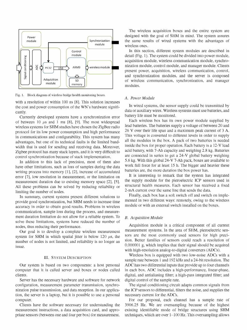
Fig. 1. Block diagram of wireless bridge health monitoring boxes.
with a resolution of within 100 ns [8]. This solution increases the cost and power consumption of the WN's hardware significantly.
Currently developed systems have a synchronization error of between 10 ¡i% and 1 ms [8], [9]. The most widespread wireless systems for SHM studies have chosen the ZigBee radio protocol for its low power consumption and high performance in communications and configurability. This system has many advantages, but one of its technical faults is the limited bandwidth that is used for sending and receiving data. Moreover, Zigbee protocol has many stack layers, and it is very difficult to control synchronization because of stack implementation.
In addition to this lack of precision, most of them also have other limitations, such as loss of samples during the data writing process into memory [1], [2], increase of accumulated error [7], low resolution in measurement, or the limitation on measurement duration due to existing memory space [2], [5]. All these problems can be solved by reducing reliability or limiting the number of nodes.
In summary, current systems present different solutions to provide good synchronization, but SHM needs to increase time accuracy in order to obtain good results. Problems in wireless communication, sample loss during the process, and measurement duration limitation do not allow for a reliable system. To solve these limitations, systems have reduced the number of nodes, thus reducing their performance.
Our goal is to develop a complete wireless measurement system for SHM in which spatial jitter is below 120 ¡i%, the number of nodes is not limited, and reliability is no longer an issue.
III. SYSTEM DESCRIPTION
Our system is based on two components: a host personal computer that it is called server and boxes or nodes called clients.
Server has the necessary hardware and software for network configuration, measurement parameter transmission, synchronization pulse transmission, and data reception. In our application, the server is a laptop, but it is possible to use a personal computer.
Clients have the software necessary for understanding the measurement instructions, a data acquisition card, and appropriate sensors (between one and four per box) for measurement.
The wireless acquisition boxes and the entire system are designed with the goal of SHM in mind. The system assures the same results of wired systems with the advantages of wireless ones.
In this section, different system modules are described in detail (Fig. 1). The system could be divided into power module, acquisition module, wireless communication module, synchronization module, control module, and manager module. Clients present power, acquisition, wireless communication, control, and synchronization modules, and the server is composed of wireless communication, synchronization, and manager modules.
A. Power Module
In wired systems, the sensor supply could be transmitted by data or auxiliary wires. Wireless systems must use batteries, and battery life must be monitored.
Each wireless box has its own power module supplied by lead batteries. The batteries supply a voltage of between 20 and 26 V over their life span and a maximum peak current of 3 A. This voltage is converted to different levels in order to supply all the modules in the box. A pack of two batteries is needed inside the box for proper operation. Each battery is a 12-V lead acid battery, with 7-Ah capacity and weighing 2.8 kg. Batteries are connected in series to get a 24-V global battery weighing 5.6 kg. With this global 24-V 7-Ah pack, boxes are available to work full force for at least 15 h. The bigger and heavier these batteries are, the more duration the box power has.
It is interesting to remark that the system has integrated the supply module for the piezoelectric ICP sensors used in structural health measures. Each sensor has received a fixed 2-mA current over the same line that sends the data.
Finally, each box has a soft switch off and switch on implemented in two different ways: remotely, owing to the wireless module or with an external switch installed on the boxes.
B. Acquisition Module
Acquisition module is a critical component of all current measurement systems. In the area of SHM, piezoelectric sensors are the most commonly used sensors for high precision. Better families of sensors could reach a resolution of 0.000001 g, which implies that their signal should be acquired with high-resolution analog-to-digital converters (ADCs).
Wireless box is equipped with two low-noise ADCs with a sample rate between 1 and 192 kHz and a 24-bit resolution. The ADC has two differential inputs that provide up to four channels in each box. ADC includes a high-performance, linear-phase, digital, and antialiasing filter; a high-pass integrated filter; and digital control of the sample rate.
The signal conditioning circuit adapts common signals from the ICP sensors to differential, filters the noise, and supplies the necessary current for the ADCs.
For our proposal, each channel has a sample rate of 3906.25 Hz. We are oversampling because of the highest existing identifiable mode of bridge structures using SHM techniques, which are over 1-100 Hz. This oversampling allows
for high temporal precision and digital filtering. For a target-sampling rate of 200 Hz, a total jitter of 120 /xs or 5% of the sampling interval is selected as the cap on total jitter [9]. The digitalized information runs through a USB interface, owing to a PIC32 microchip which creates an Serial Peripheral Interface-Universal Serial Bus gateway, to the control module.
C Synchronization Module
According to the analysis in Section II, the minimum synchronization error between two boxes has to be less than 120 fj,s. If this limit is exceeded, modal results could be affected.
We propose a wireless synchronization module based on the IEEE 802.15.4 protocol standard to achieve this requirement. A master device inside the server sends a synchronization pulse to all the slave devices inside the boxes. Sync modules have a feature which detects energy in the 2.4-GHz band and acts upon detection. The main problem for synchronization in this protocol is stack layer overhead. Call functions can delay the order from the pulse detection in the physical layer to save time in the application layer in different ways. Our solution is a direct call from physical layer to application layer, avoiding all the intermediate stack layers.
Slave module generates an interruption at the exact moment that it detects energy in its operation band. The interruption is attended to immediately in the PIC32 microcontroller, and a time reference number of sample couples are stored. We use a 32-bit timer to get this reference, which is activated in the first pulse. The 32-bit timers allow us to detect differences in the signal under 1 ns. By removing the different layers of protocol communication, the energy pulse that marks the synchronization is much faster and does not require any additional processing.
Synchronization pulses can be transmitted to the boxes at any time in order to set sync marks that will be used in the postprocess. These correct small deviations between internal oscillator-based hardware clocks. This way, the system offers full flexibility to create synchronization marks at any moment or in any setup. These pulses can be used to synchronize the boxes before placing them over the structure. Therefore, system allows for measurement of structures that are thousands of meters in size. We also include a 9-dBi external antenna which increases the coverage of the synchronization module. More sync marks can be requested during the measurement process to increase accuracy using a simple postprocessing algorithm with decimation and interpolation operations.
One pulse also synchronizes the activation of all ADCs in the boxes. That makes all the ADCs start their measurements with a minimum clock error. Tests carried out in the laboratory assure that the difference between boxes receiving the pulse is about 80 ns as we will see in Section V-A. With all these pulses, the system is able to fix the minimum derivations in the signals provoked by differences in the frequency clock of the boxes which have an error of 25 ppm.
Finally, when the measurement has been taken, the boxes send the couples' sample timer number to the server where they are analyzed. Because of the oversampling and the sync marks, the server can process the data in order synchronization
accuracy. Sync marks are sent by the server; thus, an exact time between marks is known. Frequency rate is fixed and much higher than the system needs. Therefore, two files of different boxes should have the same number of samples between marks. If a little jitter is detected, the server can interpolate or decimate samples to avoid that jitter.
To summarize, the sync module provides a great initial reference to the system, with less than 125-ns difference between all boxes. The next pulses that the boxes receive are used to fix derivations in the frequency clock. Using this approach, we obtain good first initial pulse synchronization and correct internal deviation and provide a reliable test.
D. Wireless Communication Module
As explained in Section I, the wired systems have some inconveniences that wireless systems try to resolve, like the cost of the wires, the deployment of the system on the structures, etc.
The system presented in this paper uses the 802.11 protocol, also known as Wi-Fi, for communications between the boxes on the structure and the server that runs on a laptop. This protocol uses an Industrial, Scientific and Medical band, which does not need a licensed spectrum band. This way, all communication packets are sent via Wi-Fi using its large bandwidth, and Zigbee radio interface is dedicated only to synchronization.
The wireless box has a wireless interface connected to the main board equipped with drivers to control and configure the device. In the same way, the laptop has a wireless interface which has the ability to create WNs in infrastructure mode.
The server acts as an access point (AP), and all the boxes connect to this AP. The network configuration is automatic. The server generates a Wi-Fi network with WEP or WPA protection where clients are allowed to connect. WEP and WPA are two systems used to protect Wi-Fi networks. Wireless encryption protocols are used to avoid external access to the communications carried out during measurements. It is possible to add as many clients as there are boxes, and they are automatically assigned an IP address. This feature provides us with a scalable architecture. Once clients are connected, they are available to receive instructions or ready to receive secure communications through Secure SHell (SSH). Secure communications are needed due to the management of critical data.
SSH allows the server to establish a secure communication with all the boxes on the structure to monitor. In this way, no one without the secure key can access the boxes or the collected data.
Wireless and remote security issues have been taken into account because of the importance of the data. However, direct access to the boxes is not an important issue because, as we will see in Section IV, the boxes are not a permanent monitoring system. An operator should stay on the bridge watching over it throughout the whole measurement process, avoiding the possibility of a direct access attack.
E. Control Module
Control module is responsible for managing all previous modules. It is based on an ARM9 microcontroller running
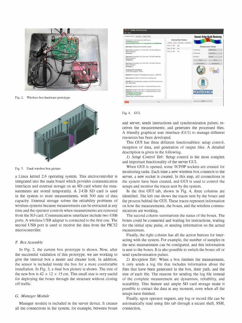
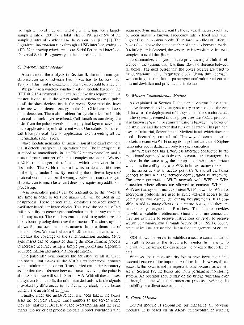
Fig. 2. Wireless box hardware prototype.
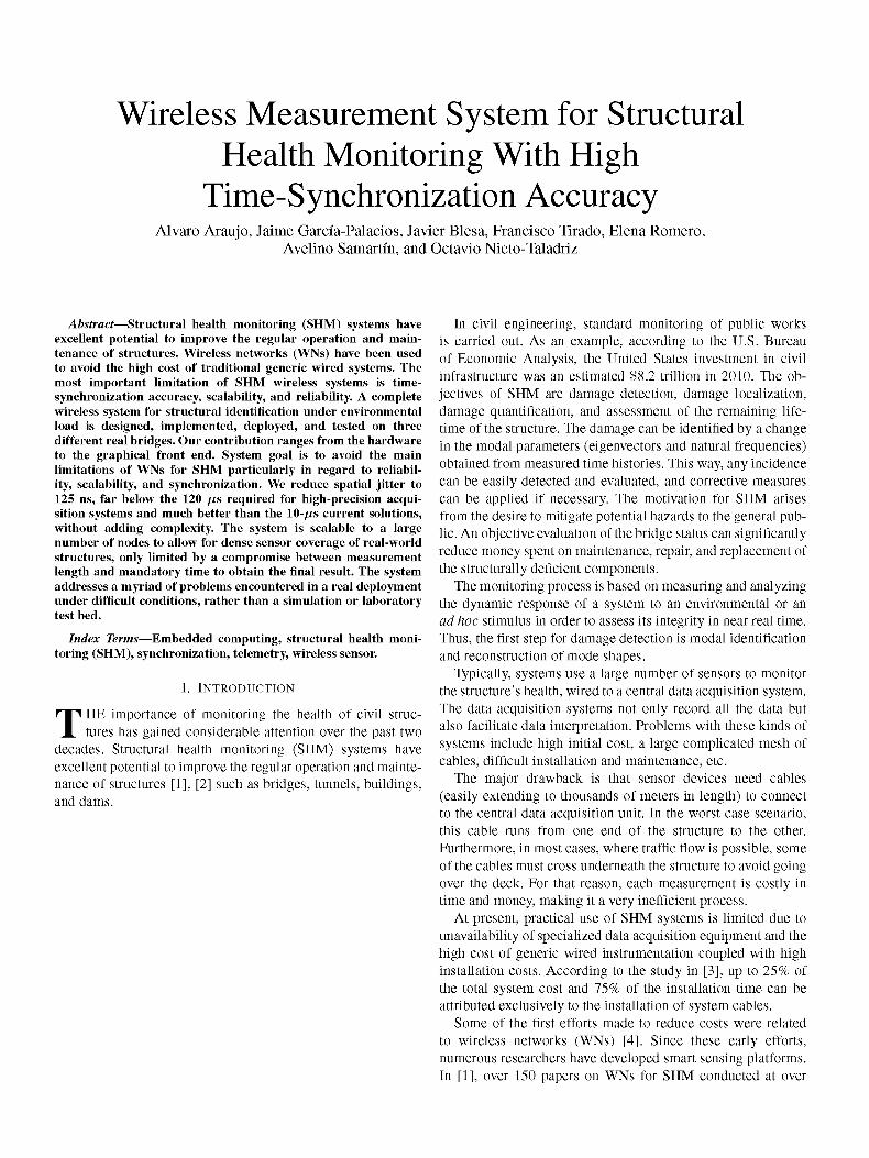
Fig. 3. Final wireless box picture.
a Linux kernel 2.6 operating system. This microcontroller is integrated into the main board which provides communication interfaces and external storage on an SD card where the measurements are stored temporarily. A 2-GB SD card is used in the system to store measurements, with 500 min of data capacity. External storage solves the reliability problems of wireless systems because measurements can be extracted at any time and the operator controls when measurements are removed from the SD card. Communication interfaces include two USB ports. A wireless USB adapter is connected to the first one. The second USB port is used to receive the data from the PIC32 microcontroller.
F. Box Assemble
In Fig. 2, the current box prototype is shown. Now, after the successful validation of this prototype, we are working to give the internal box a neater and cleaner look. In addition, the sensor is included inside the box for a more comfortable installation. In Fig. 3, a final box picture is shown. The size of the new box is 42 x 12 x 15 cm. This small size is very useful for deploying the boxes through the structure without closing off traffic.
G. Manager Module
Manager module is included in the server device. It creates all the connections in the system, for example, between boxes
[Server] Connection 1: IP:192.168.1. been establish. «Clients: 1
[Server] Connection 2: IPM92.168.1.14 PORT:3969 has been establish. «Clients: 2
[Server] Connection 3: IP:192.168.1.1SP0RT:4375 has been establish. «Clients: 3
[Shell] 'OK Number of Samples to measure = 23437501
[Server] instruction: cn23437S0 is already sent.
[Client] Conection 192.168.1.15: Received instruction
[Client] Conection I92.i68.i.i6; Received Instruction [Client] Conection I92.i68.ii4: Received instruction Initializing Syncronlsm... Starting the measure Please, wait until the measure has finished
Box_1S OK
BoxJ6 OK
Choose your setup
Frequency
N Samples
Duration
send
3906.25 Hi
2.343.750
10 min
start
• " •
EÜES22
=s
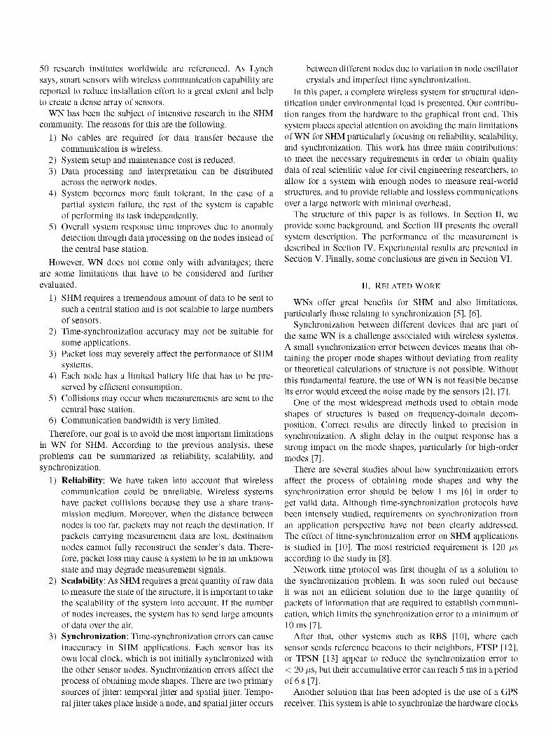
Fig. 4. GUI.
and server; sends instructions and synchronization pulses; receives the measurements; and generates the processed files. A friendly graphical user interface (GUI) to manage different resources has been developed.
This GUI has three different functionalities: setup control, reception of data, and generation of output files. A detailed description is given in the following.
1) Setup Control Tab: Setup control is the most complex and important functionality of the server GUI.
When GUI is opened, some TCP/IP sockets are created for monitoring tasks. Each time a new wireless box connects to the server, a new socket is created. In this step, all connections in the system have been created, and GUI is used to control the setups and monitor the traces sent by the system.
In the first GUI tab, shown in Fig. 4, three columns are identified. The left one shows the traces sent by the boxes and the process behind the GUI. These traces represent information on how the measurements, the boxes, and the wireless communications are working.
The second column summarizes the status of the boxes. The boxes could be connected and waiting for instructions, waiting for the initial sync pulse, or sending information on the actual measurement.
Finally, the right column has all the action buttons for interacting with the system. For example, the number of samples in the next measurement can be configured, and this information is sent to the boxes. It is also possible to switch the boxes off or send synchronization pulses.
2) Reception Tab: When a box finishes the measurement, it only sends a log file that includes information about the files that have been generated in the box, their path, and the size of each file. The reasons for sending the log file instead of the complete measurement are dynamism, reliability, and scalability. This feature and ample SD card storage make it possible to extract the data at any moment, even when all the setups have finished.
Finally, upon operator request, any log or record file can be automatically read using this tab through a secure shell, SSH, connection.
3) Generation Output File Tab: The boxes store the data in binary files in the same way that the ADCs send the samples. This reduces the amount of memory needed in the boxes as the server has significantly more resources to manage the great amount of data. For example, a normal 10-min measurement in one box with a frequency of 3906.25 implies more than 2 million samples.
These binary data should be converted to ASCII files which are readable by different data processing programs.
IV. MEASUREMENTS
In this section, a measurement process is explained in order to understand the importance of reliability, scalability, and synchronization.
The described wireless monitoring system is designed with the purpose of measuring multiple structures on the same day. Thus, the operator deploys the boxes over a bridge, and the clients of each box start the connections. Later, when the measurements are finished, the boxes can be used to measure a new bridge.
In movable dynamic monitoring systems used for structural identification under operational (environmental) loads, traffic cannot be closed off for a great number of candidate structures during the tests. Wireless interface and box size allow for measurements to be taken with regular traffic. The full process consists of the following: making a finite-element model (FEM) or structural model in order to decide upon the best suitable monitoring locations for the sensors; placing sensors on a stiff plate with a levelling system and leveling them; performing the test, postprocessing of the data to get the eigenmodes and frequencies; and removing the sensors. All these steps for a three-span bridge with a total length of 100 m can be done in a little over 2 h.
A. Measurement Setup Process
Once at least one client has been connected, user can select one of these two parameters: number of samples or duration of the measurement. By choosing one of the two parameters, the other is automatically obtained once the measurement frequency is set, i.e., 3906.25 Hz. Measurements are always carried out at a resolution of 24 bits. When the measurement parameters are set, the submit button is pressed, and instructions are broadcast by Wi-Fi to each box. The GUI allows for controlling which boxes have received the proper instruction.
When an instruction is received by the boxes, those enter into a waiting state pending the synchronization pulse needed in order to start the measurement. The measurement process has priority over any other process in the system and thus ensures no loss of samples in the measurement process.
B. Synchronism
User can start the measurement by pressing the corresponding button on the GUI. With this action, a pulse is sent over the 802.15.4 protocol, which is received by the boxes, automatically starting the measurement.
Note that two different protocols are used: Wi-Fi for communication instructions and transmission/reception of data and IEEE 802.15.4 for synchronization. Thus, the synchronization is instantaneous and does not need to travel through any communication layer.
On the GUI, user can see the evolution of the measurement through a progress bar that indicates what percentage of the measurement has been performed.
C. Data Transmission and Saving Process
Each box stores the four-binary parallel channel data on an SD memory card, and when the measurement time is finished, a command is sent to the server with the name of the stored files, as well as the path and size.
A new measurement can be started from the server, or data from this or previous measurements that are stored on the SD card of any connected box can be retrieved. The server requests data from the nodes in order to avoid collisions. Nevertheless, MAC protocol of 802.11 can retransmit packets to recover lost data.
Connection and data sending are carried out through SSH connection. Transmission speed may vary, but on average, it is at a rate of 1.3 MB/s.
Once binary data are received from the different boxes, it is possible to decode and generate ASCII text files. This decoding process can be performed in parallel with the measurement process because it only works on the server. Moreover, data reception can be performed in parallel with measurement, but as discussed earlier, the measurement process takes priority, so the data transmission rate is highly reduced. Therefore, it is not recommended to do this.
D. Plotting the Results
With the GUI, individual files for every channel of each box, as well as a single file with one column for each selected channel, can be generated. This file will be processed by SHM applications.
Another advantage of GUI is that it incorporates a window display to graphically represent the desired channels.
V. RESULTS
In order to validate the system, three different tests have been carried out. First, the synchronization module is checked in the lab. In the second step, an operational modal analysis (OMA) is carried out on a real structure. Finally, the signals corresponding to two accelerometers, placed on the structure at the same location but with different acquisition boxes, are compared.
A. Synchronization Test in the Laboratory
As we can see in Section II, time synchronization is one of the most important issues in wireless SHM. We have to check two types of time-synchronization problems: The first one is temporal jitter, and the second is spatial jitter. A temporal jitter,
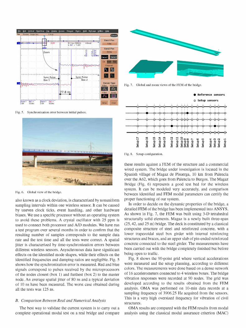
Fig. 5. Synchronization error between initial pulses.
Fig. 6. Global view of the bridge.
also known as a clock deviation, is characterized by nonuniform sampling intervals within one wireless sensor. It can be caused by uneven clock ticks, event handling, and other hardware biases. We use a specific processor without an operating system to avoid these problems. A crystal oscillator with 25 ppm is used to connect both processor and A/D modules. We have run a test program over several months in order to confirm that the resulting number of samples corresponds to the sample data rate and the test time and all the tests were correct. A spatial jitter is characterized by time-synchronization errors between different wireless sensors. Asynchronous data have significant effects on the identified mode shapes, while their effects on the identified frequencies and damping ratios are negligible. Fig. 5 shows how the synchronization error is measured. Red and blue signals correspond to pulses received by the microprocessors of the nodes closest (box 1) and furthest (box 2) to the master node. An average spatial jitter of 80 ns and a typical deviation of 10 ns have been measured. The worst case obtained during all the tests was 125 ns.
B. Comparison Between Real and Numerical Analysis
The best way to validate the current system is to carry out a complete operational modal test on a real bridge and compare
Fig. 7. Global and zoom views of the FEM of the bridge.
• Reference sensors
O Setup sensors
O •• O—O-O 0-O"00»-0—o-o o-OO — O
Q O O-O-O O - O - Q O O - O - O - O O " 0 " 0 - " 0 '
O O O—O-O ••••O-OOO—O—O—0 O-»-0—-O'
r- u> in «r m O I * H O a. a. o . o . o . 0 . 0 . 0 . 0 . 0 . 0 . 0 . a . 0 . 0 . 0 . a . =3 =3 =3 =J =3 1 3 : 3 : 3 : 3 = 3 1 3 = 3 = 3 = 3 = 3 = 3 3 0} tu 0} a> a) a ) < u ( D ( i > Q ) a > a > ( i > <u <u 0} <D
vt t/> %n «/> i/> u l w i A i n w t n v i t n n n w «
Fig. 8. Setup configuration.
these results against a FEM of the structure and a commercial wired system. The bridge under investigation is located in the Spanish village of Magaz de Pisuerga, 10 km from Palencia over the A62, which goes from Palencia to Burgos. The Magaz Bridge (Fig. 6) represents a good test bed for the wireless system. It can be modeled very accurately, and comparison between identified and FEM modal parameters can certify the proper functioning of our system.
In order to decide on the dynamic properties of the bridge, a detailed FEM of the bridge has been implemented into ANSYS. As shown in Fig. 7, the FEM was built using 3-D tetrahedral structurally solid elements. Magaz is a newly built three-span (25,42, and 25 m) bridge. The deck is constituted by a classical composite structure of steel and reinforced concrete, with a lower trapezoidal steel box girder with internal reinforcing structures and braces, and an upper slab of pin-ended reinforced concrete connected to the steel girder. The measurements have been carried out with the bridge completely finished but before being open to traffic.
Fig. 8 shows the 90-point grid where vertical accelerations were measured and the setup planning, according to different colors. The measurements were done based on a dense network of 16 accelerometers connected to 4 wireless boxes. The bridge vibration responses were recorded at 90 nodes. The grid was developed according to the results obtained from the FEM analysis. OMA was performed on 10-min data records at a sampling frequency of 3906.25 Hz acquired from the sensors. This is a very high oversized frequency for vibration of civil structures.
OMA results are compared with the FEM results from modal analysis using the classical modal assurance criterion (MAC)
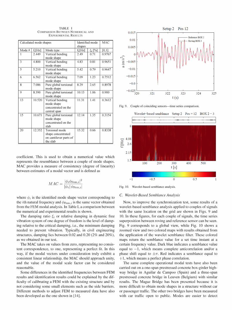
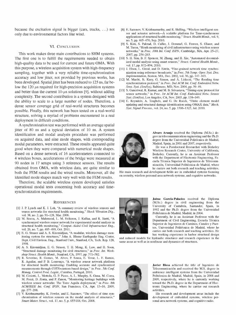
TABLE I COMPARISON BETWEEN NUMERICAL AND
EXPERIMENTAL RESULTS
Setup 2 Pos 12
Calculated mode shapes
Mode# 1
3
5
6
8
9
13
15
20
fi[Hz] 2.449
4.800
5.210
6.562
7.086
8.390
10.520
10.671
12.352
Mode type Vertical bending mode shape Vertical bending mode shape Vertical bending mode shape Vertical bending mode shape Pure global torsional mode shape Pure global torsional mode shape Vertical bending mode shape concentrated on the central span Pure global torsional mode shape concentrated on the slab Torsional mode shape concentrated on cantilever parts of the slab
Identified mode shapes fi[Hz] 2.49
4.83
5.42
7.09
8.29
10.13
11.31
12.14
15.32
h [%] 0.71
0.81
0.79
1.23
2.65
1.06
1.41
1.35
0.66
MAC
[0,1] 0.9767
0.9651
0.9647
0.7512
0.8978
0.900
0.3612
0.3154
0.8338
coefficient. This is used to obtain a numerical value which represents the resemblance between a couple of mode shapes. MAC provides a measure of consistency (degree of linearity) between estimates of a modal vector and is defined as
MAC ^Fem,i
9Fem,¿|
where </>¿ is the identified mode shape vector corresponding to the ith natural frequency and (j)Fem,i is the same vector obtained from the FEM modal analysis. In Table I, a comparison between the numerical and experimental results is shown.
The damping ratio £¿ or relative damping in dynamic free vibration system of one degree of freedom is the level of damping relative to the critical damping, i.e., the minimum damping needed to prevent vibration. Typically, in civil engineering structures, damping lies between 0.02 and 0.20 (2% and 20%), as we obtained in our test.
The MAC takes on values from zero, representing no consistent correspondence, to one, representing a perfect fit. In this way, if the modal vectors under consideration truly exhibit a consistent linear relationship, the MAC should approach unity, and the value of the modal scale factor can be considered reasonable.
Some differences in the identified frequencies between FEM results and identification results could be explained by the difficulty of calibrating a FEM with the existing structure and by not considering some small elements such as the side barriers. Different methods to adjust FEM to measured data have also been developed as the one shown in [14].
-0.025 320 321 323 324 325
t(s)
Fig. 9. Couple of coinciding sensors—time series comparison.
Wavelet-based semblance Setup 2 Pos = 12 BOX 2 - 3
8
^ 4 . 0 8
£ 2.6
2.15
15 I^HHi H 100 200 300
t[s] 400 500
0.5
Fig. 10. Wavelet-based semblance analysis.
C. Wavelet-Based Semblance Analysis
Now, to improve the synchronization test, some results of a wavelet-based semblance analysis applied to couples of signals with the same location on the grid are shown in Figs. 9 and 10. In these figures, for each couple of signals, the time series superposition between roving and reference sensor can be seen. Fig. 9 corresponds to a global view, while Fig. 10 shows a zoomed view and two colored maps with results obtained from the application of the wavelet semblance filter. These colored maps return the semblance value for a set time instant at a certain frequency value. Dark blue indicates a semblance value equal to —1, which means complete anticorrelation and/or a phase shift equal to ±7r. Red indicates a semblance equal to + 1, which means a perfect phase correlation.
The same complete operational modal tests have also been carried out on a one-span prestressed concrete box-girder highway bridge in Aguilar de Campoo (Spain) and a three-span prestressed concrete bridge in Leu ven (Belgium) with similar results. The Magaz Bridge has been presented because it is more difficult to obtain mode shapes in a structure without car or passenger traffic. The other two bridges have been measured with car traffic open to public. Modes are easier to detect
because the excitation signal is bigger (cars, trucks, . . .) not only due to environmental factors like wind.
VI. CONCLUSION
This work makes three main contributions to SHM systems. The first one is to fulfill the requirements needed to obtain high-quality data to be used for current and future OMA. With this purpose, a wireless acquisition system with high-frequency sampling, together with a very reliable time-synchronization accuracy and low jitter, not provided by previous works, has been developed. Spatial jitter has been reduced to 125 ns, far below the 120 /xs required for high-precision acquisition systems and better than the current 10-/xs solutions [9], without adding complexity. The second contribution is a system designed with the ability to scale to a large number of nodes. Therefore, a dense sensor coverage grid of real-world structures becomes possible. Finally, this network has been tested on a real-world structure, solving a myriad of problems encountered in a real deployment in difficult conditions.
A synchronization test was performed with an average spatial jitter of 80 ns and a typical deviation of 10 ns. A system identification and modal analysis procedure was performed on acquired data, and nine mode shapes, with corresponding modal parameters, were extracted. These results appeared quite good when they were compared with numerical mode shapes. Based on a dense network of 16 accelerometers connected to 4 wireless boxes, accelerations of the bridge were measured at 90 nodes in 17 setups using 3 reference sensors. The results obtained from OMA, with wireless data, are quite similar to both the FEM results and the wired results. Moreover, all the identified mode shapes match very well with the FEM results.
Therefore, the scalable wireless system developed satisfies operational modal tests concerning both accuracy and time-synchronization requirements.
REFERENCES
[1] J. P. Lynch and K. J. Loh, "A summary review of wireless sensors and sensor networks for structural health monitoring," Shock Vibration Dig., vol. 38, no. 2, pp. 91-128, Mar. 2006.
[2] M. Bocea, A. Mahmood, L. M. Eriksson, J. Kullaa, and R. Jántti, "A synchronized wireless sensor network for experimental modal analysis in structural health monitoring," Comput.-Aided Civil Infrastructure Eng., vol. 26, no. 7, pp. 483-499, Oct. 2011.
[3] E. G. Straser and A. S. Kiremidjian, "A modular, wireless damage monitoring system for structures," John A. Blume Earthquake Eng. Center, Dept. Civil Environ. Eng., Stanford Univ., Stanford, CA, Tech. Rep. 128,
[4] A. S. Kiremidjian, E. G. Straser, T. H. Meng, K. Law, and H. Soon, "Structural damage monitoring for civil structures," in Proc. Int. Workshop Struct. Health Monit., Stanford, CA, 1997, pp. 371-382.
[5] R. Severino, R. Gomes, M. Alves, P. Sousa, E. Tovar, L. F. Ramos, R. Aguilar, and P. B. Lourenco, "A wireless sensor network platform for structural health monitoring: Enabling accurate and synchronized measurements through COTS+custom-based design," in Proc. 5th Conf. Manag. Control Prod. Logist., Coimbra, Portugal, 2010.
[6] M. Ceriotti, L. Mottola, G. P. Picco, A. L. Murphy, S. Guna, M. Corra, M. Pozzi, D. Zonta, and P. Zanon, "Monitoring heritage buildings with wireless sensor networks: The Torre Aquila deployment," in Proc. 8th ACM/IEEE Int. Conf. IPSN, San Francisco, CA, Apr. 13-16, 2009, pp. 277-288.
[7] V. Krishnamurthy, K. Fowler, and E. Sazonov, "The effect of time synchronization of wireless sensors on the modal analysis of structures," Smart Mater. Struct., vol. 17, no. 5, p. 055018, Oct. 2008.
[8] E. Sazonov, V. Krishnamurthy, and R. Shilling, "Wireless intelligent sensor and actuator network—A scalable platform for Time-synchronous applications of structural health monitoring," Struct. Health Monit., vol. 9, no. 5, pp. 465^176, Sep. 2010.
[9] S. Kim, S. Pakzad, D. Culler, J. Demmel, G. Fenves, S. Glaser, and M. Turon, "Heath monitoring of civil infrastructures using wireless sensor networks," in Proc. 10th Int. Conf. ISPN, Cambridge, MA, Apr. 25-27, 2007, pp. 254-263.
[10] S. H. Sim, B. F. Spencer, M. Zhang, and H. Xie, "Automated decentralized modal analysis using smart sensors," Struct. Control Health Monit., vol. 17, pp. 872-894, 2010.
[11] J. Elson, L. Girod, and D. Estrin, "Fine-grained network time synchronization using reference broadcasts," in Proc. 5th Symp. Oper. Syst. Des. Implementation, Boston, MA, Dec. 2002, vol. 36, pp. 147-163.
[12] M. Maróti, B. Kusy, G. Simon, and A. Lédeczi, "The flooding time synchronization protocol," in Proc. 2nd ACM Int. Conf. Embedded Netw. Sens. Syst. (SenSys), Baltimore, MD, Nov. 2004, pp. 39-49.
[13] S. Ganeriwal, R. Kumar, and M. B. Srivastava, "Timing-sync protocol for sensor networks," in Proc. 1st ACM Int. Conf. Embedded Netw. Sensor Syst. (SenSys), Los Angeles, CA, Nov. 2003, pp. 138-149.
[14] E. Reynders, A. Teughels, and G. De Roeck, "Finite element model updating and structural damage identification using OMAX data," Mech. Syst. Signal Process., vol. 24, no. 5, pp. 1306-1323, Jul. 2010.
Alvaro Araujo received the Diploma (M.Sc.) degree in telecommunication engineering and the Ph.D. degree from the Universidad Politécnica de Madrid, Madrid, Spain, in 2001 and 2007, respectively.
He was a Postdoctoral Researcher with Berkeley Wireless Research Center, University of California, Berkeley. Currently, he is an Assistant Professor with the Department of Electronic Engineering, Escuela Técnica Superior de Ingenieros de Telecomunicación, Universidad Politécnica de Madrid, where he carries out both research and teaching activities.
His main research and development fields are in embedded systems focusing on security, wireless personal area network systems, and cognitive networks.
Jaime García-Palacios received the Diploma (M.Sc.) degree in civil engineering from the University of Cantabria, Santander, Spain, in 1992 and the Ph.D. degree from the Universidad Politécnica de Madrid, Madrid, in 2004.
Currently, he is an Assistant Professor with the Department of Civil Engineering, Escuela Técnica Superior de Ingenieros de Caminos, Canales y Puertos, Universidad Politécnica de Madrid, where he carries out both research and teaching activities. He has working experience in harbor structural design
and reduced models for hydraulic structures and research experience in the same areas as well as in nonlinear and dynamics of structures.
Javier Blesa achieved the title of Ingeniero de Telecomunicación and received the M.S. degree in ambience intelligent systems from the Universidad Politécnica de Madrid, Madrid, Spain, in 2008 and 2009, respectively, where he is currently working toward the Ph.D. degree in the Department of Electronic Engineering, where he carries out research activities.
His research and development areas include the development of embedded systems, wireless personal area network systems, and cognitive radio.

Francisco Tirado achieved the title of Information and Communication Technology Engineer from the Universidad Politécnica de Madrid, Madrid, Spain, and received the Master of Science in Engineering degree from the Royal Institute of Technology (KTH), Stockholm, Sweden, in 2010.
He carries out research activities in the Department of Civil Engineering: Hydraulics and Energetics, Universidad Politécnica de Madrid. Currently, he is working in collaboration with the Department of Electronic Engineering, where his development
areas are focused in new wireless acquisition systems for health monitoring
Elena Romero received the Diploma of Ingeniera de Telecomunicación degree from the Universidad Politécnica de Madrid, Madrid, Spain, in 2007, where she is currently working toward the Ph.D. degree in the area of electronic engineering.
Her main research and development fields include the development of embedded systems focusing on cognitive radio, wireless sensor networks, low power, security, and development and integration of applications in ambient intelligence.
Avelino Samartin achieved the title of Civil Engineer (Ingeniero de Caminos, Canales y Puertos) from the Universidad Politécnica de Madrid (UPM), Madrid, Spain, in 1963 and received the Licenciado (B.Sc.) degree in mathematics from the University of Santiago de Compostela, Santiago de Compostela, Spain, in 1965, the Ph.D. degree in civil engineering and the B.Sc. degree in computer science from the UPM, in 1967 and 1972, respectively, and the Diploma of the Imperial College from Imperial College London, London, U.K., in 1967.
He was a Visiting Scholar with the University of California, Berkeley, in 1973. He was a Professor in bridge analysis and design with UPM from 1974 to 1976, in structural mechanics with the University of Santander from 1976 to 1987, and in strength of materials with UPM from 1987 to 2010. He is currently an Emeritus Professor with UPM with main research interest on computer methods applied to structural analysis. He has supervised 19 Ph.D. theses. He is the author of more than 150 scientific papers and 21 technical books.
Dr. Samartin is a member of several organizations: Royal Swedish Academy of Engineering (IVA), Spanish Association of Seismic Engineering (AEIS), and International Association for Shell and Spatial Structures (IASS) where he occupied several positions within the Working Bureau and the Executive Council of the Association. He has also been the Founder and Chairman of the IASS Working Group 13 "Numerical Methods for Shell and Space structures." He has been distinguished for his technical contributions with several medals and prizes (Juan March grants, Atazar medal, Jose Toran Prize, medal of UPM, medal of the Colegio de Ingenieros de Caminos, Canales y Puertos for his Professional achievements, etc).
AM in dynamic structures.
*Yt
Octavio Nieto-Taladriz achieved the title of "Ingeniero de Telecomunicación" and received the Ph.D. degree from the Universidad Politécnica de Madrid, Madrid, Spain, in 1984 and 1989, respectively.
Currently, he is a Full Professor and the Head of the Departamento de Ingeniería Electrónica, Escuela Técnica Superior de Ingenieros de Telecomunicación, Universidad Politécnica de Madrid, were he carries out both research and teaching activities. He is also currently the Deputy Director of the research group Laboratorio de Sistemas Integrados.
His main research and development fields are in the development of embedded systems, including microelectronics (ASIC's) and rapid prototyping based on field-programmable gate arrays, high-performance digital architectures mainly focused on broadband radio communications, and the development and integration of services and applications for mobility over heterogeneous communication platforms, security, ambient intelligence, and domotics.
'S^r^