Embed Size (px)
Citation preview
HAL Id: hal-00878112https://hal.archives-ouvertes.fr/hal-00878112
Submitted on 29 Oct 2013
HAL is a multi-disciplinary open accessarchive for the deposit and dissemination of sci-entific research documents, whether they are pub-lished or not. The documents may come fromteaching and research institutions in France orabroad, or from public or private research centers.
L’archive ouverte pluridisciplinaire HAL, estdestinée au dépôt et à la diffusion de documentsscientifiques de niveau recherche, publiés ou non,émanant des établissements d’enseignement et derecherche français ou étrangers, des laboratoirespublics ou privés.
Wireless Sensing and Identification based on RADARCross Sections Variability Measurement of Passive
Electromagnetic SensorsHervé Aubert, Franck Chebila, Mohamed Mehdi Jatlaoui, Trang Thai,
Hamida Hallil, Anya Traille, Sofiene Bouaziz, Ayoub Rifai, Patrick Pons,Philippe Menini, et al.
To cite this version:Hervé Aubert, Franck Chebila, Mohamed Mehdi Jatlaoui, Trang Thai, Hamida Hallil, et al.. Wire-less Sensing and Identification based on RADAR Cross Sections Variability Measurement of PassiveElectromagnetic Sensors. Annals of Telecommunications - annales des télécommunications, Springer,2013, 68 (7-8), pp.425-435. <hal-00878112>
Submitted to Annals of Telecommunications Special Issue on Chipless RFID Original version submitted : July 12, 2012
Review report : February 6, 2013 Revised version : February 6, 2013
Wireless Sensing and Identification based on RADAR Cross Sections Variability Measurement of
Passive Electromagnetic Sensors
AUBERT Hervé1,2, CHEBILA Franck1,2, JATLAOUI Mehdi3, THAI Trang4, HALLIL Hamida5,
TRAILLE Anya1,2, BOUAZIZ Sofiene1,2, RIFAÏ Ayoub1,2, PONS Patrick1, MENINI Philippe1,2 and TENTZERIS Manos4 1 LAAS‐CNRS, 7 avenue du Colonel Roche, F‐31077 Toulouse, France and
2 University of Toulouse; UPS, INSA, INP, ISAE; F‐31077 Toulouse, France
3 IPDIA, 2 rue de la Girafe, 14000 Caen, France
4 School of ECE, Georgia Institute of Technology, Atlanta, GA 30332, U.S.A.
5 University of Bordeaux, Laboratory IMS, CNRS UMR 5218, IPB, Univ. Bordeaux 1, Talence, France
Corresponding author : email: [email protected]; phone number : 33‐6‐33‐74‐81‐72
Abstract ‐ In this paper we present the wireless measurement of various physical quantities from the analysis of the RADAR Cross Sections (RCS) variability of passive electromagnetic sensors. The technique uses a millimeter Frequency‐Modulated Continuous‐Wave (FMCW) RADAR for both remote sensing and wireless identification of sensors. Long reading ranges (up to some decameters) is reached at the expense of poor measurement resolution (typically 10%). A review of recent experimental results is reported for illustration purpose. Keywords : wireless sensors network – passive sensor – remote sensing – backscattering – Frequency modulation – FMCW RADAR – millimeter‐wave – chipless RFID
I. Introduction
Passive (battery‐less) and wireless sensors are very good candidates for measuring physical quantities in harsh environment (e.g., high radiation or extreme temperature) and/or for applications requiring sensing devices with low‐cost of fabrication, small size and long‐term measurement stability. In 2007 the authors report the first passive pressure sensing device based on an electromagnetic (EM) transduction [1]. The EM sensing device converts the variation of an applied pressure into a variation of millimeter‐wave resonant frequency of a resonator. In general passive EM sensing devices convert the variation of a physical quantity (such as, e.g., pressure, temperature or gas concentration) into a known/specific variation of a given electromagnetic wave descriptor. These devices are battery‐free and chip‐less. Based on the EM transduction the first gas sensor was presented in 2004 by Grath et al. [2] and the first strain sensor was reported in 2005 by Chuang et al. [3]. Unlike devices based on Surface Acoustic Waves (see, e.g., [4]‐[7]) EM sensing devices do not require electromagnetic‐to‐acoustic wave conversion and consequently avoid high losses involved in this conversion. One survey of original passive EM sensing devices developed by the authors since 2007 is given in Section II (for a complete review, see [8]). The wireless measurement of a physical quantity from the analysis of the RADAR Cross Section (RCS) variability of passive sensors was proposed for the first time by the authors in 2008 [9] while the proof‐of‐concept was demonstrated in 2010 [10]. A Frequency‐Modulated Continuous‐Wave
Submitted to Annals of Telecommunications Special Issue on Chipless RFID Original version submitted : July 12, 2012
Review report : February 6, 2013 Revised version : February 6, 2013
(FMCW) RADAR was used for the measurement of pressure‐dependent RCS variation and for the remote derivation of the applied pressure changes. As shown in Section III.1 the wireless sensing technique based on RCS‐variability measurement has been successfully applied to the remote estimation of other physical quantities such as temperature [11]‐[15]. We have not found reports published before our first papers [9][10] where the physical quantity is directly used for the RCS amplitude modulation of passive EM sensors and then remotely measured from FMCW RADAR interrogation. The wireless identification of passive and chipless EM sensors may be based on multi‐band microwave resonators for encoding data into a specific spectral signature or microwave barcode [16]‐[18]. By using an Ultra‐WideBand (UWB) reader such barcode may be remotely detected. An alternative approach consists of creating a low‐frequency barcode in the beat frequency (or Intermediate Frequency) spectrum synthesized by the FMCW RADAR [19]. As shown in Section III.3 the wireless identification of sensors may then be based on FMCW RADAR measurement of the time‐arrivals of multiple echoes controlled by delay lines. This approach features the advantage of eliminating the challenging fabrication of UWB readers requiring, e.g., an Analog‐to‐Digital Converter with very high sampling rate. Our wireless system uses the same FMCW RADAR reader for both remote sensing and sensors identification. As shown in Section III.2 it is convenient for long reading ranges (up to some decameter) but does not yield, at least in its present version, to high measurement resolution of physical quantities. The paper is organized as follows. Section II presents a survey of original passive EM sensing devices developed by the authors since 2007. Section III is devoted to proof‐of‐concept experiments on the remote reading and wireless identification of passive EM sensors utilizing RCSs variability measurement. The choice of a millimeter‐wave FMCW RADAR reader for remote sensing and identification purposes is discussed and the feasibility of long‐range reading (over several decameters) is illustrated. Conclusion and perspectives are presented in Section IV.
II. Passive EM sensing device In this section a survey of original passive EM devices developed by the authors during the last five years is reported. The devices are based on millimeter‐ or micro‐wave resonators. They convert the variation of a physical quantity into a variation of a resonant frequency. Using high‐Q resonances high sensitivity and high measurement precision are expected. The sensing devices reported here do not need signal conditioning and space for an on‐chip power supply. They are battery‐less and chip‐less.
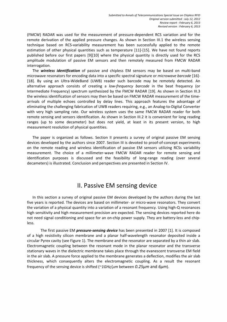
The first passive EM pressure‐sensing device has been presented in 2007 [1]. It is composed of a high resistivity silicon membrane and a planar half‐wavelength resonator deposited inside a circular Pyrex cavity (see Figure 1). The membrane and the resonator are separated by a thin air slab. Electromagnetic coupling between the resonant mode in the planar resonator and the transverse stationary waves in the dielectric membrane takes place through the evanescent transverse EM field in the air slab. A pressure force applied to the membrane generates a deflection, modifies the air slab thickness, which consequently alters the electromagnetic coupling. As a result the resonant
frequency of the sensing device is shifted (~1GHz/m between 0.25μm and 6μm).
Submitted to Annals of Telecommunications Special Issue on Chipless RFID Original version submitted : July 12, 2012
Review report : February 6, 2013 Revised version : February 6, 2013
(a) (b) (c)
Figure 1 : The first passive pressure‐sensing device based on electromagnetic transduction:
(a) fabricated device for operating in the millimeter‐wave frequency range (3,8mmx5,8mmx1,4mm); (b) view of the planar half‐wavelength resonator deposited inside a circular Pyrex cavity and (c) view of the high resistivity silicon membrane placed at the top of the planar resonator
From the measurement of this frequency shift the variation of the applied pressure can be derived. High sensitivity to the applied pressure may be obtained due to the abrupt spatial variation of the transverse evanescent EM field in the air slab. The sensor exhibits a measured sensitivity of 370MHz/bar between 0 to 3 bars. This corresponds to a relative frequency shift close to 27% of the full‐scale measurement range (Details about this first pressure‐sensing prototype may be found in [1][9][20]‐[24]).
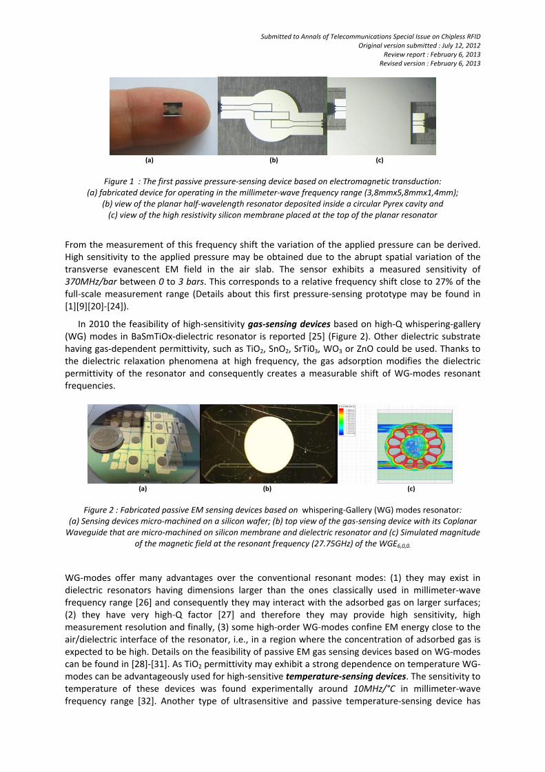
In 2010 the feasibility of high‐sensitivity gas‐sensing devices based on high‐Q whispering‐gallery (WG) modes in BaSmTiOx‐dielectric resonator is reported [25] (Figure 2). Other dielectric substrate having gas‐dependent permittivity, such as TiO2, SnO2, SrTi03, WO3 or ZnO could be used. Thanks to the dielectric relaxation phenomena at high frequency, the gas adsorption modifies the dielectric permittivity of the resonator and consequently creates a measurable shift of WG‐modes resonant frequencies.
(a) (b) (c)
Figure 2 : Fabricated passive EM sensing devices based on whispering‐Gallery (WG) modes resonator:
(a) Sensing devices micro‐machined on a silicon wafer; (b) top view of the gas‐sensing device with its Coplanar Waveguide that are micro‐machined on silicon membrane and dielectric resonator and (c) Simulated magnitude
of the magnetic field at the resonant frequency (27.75GHz) of the WGE6,0,0.
WG‐modes offer many advantages over the conventional resonant modes: (1) they may exist in dielectric resonators having dimensions larger than the ones classically used in millimeter‐wave frequency range [26] and consequently they may interact with the adsorbed gas on larger surfaces; (2) they have very high‐Q factor [27] and therefore they may provide high sensitivity, high measurement resolution and finally, (3) some high‐order WG‐modes confine EM energy close to the air/dielectric interface of the resonator, i.e., in a region where the concentration of adsorbed gas is expected to be high. Details on the feasibility of passive EM gas sensing devices based on WG‐modes can be found in [28]‐[31]. As TiO2 permittivity may exhibit a strong dependence on temperature WG‐modes can be advantageously used for high‐sensitive temperature‐sensing devices. The sensitivity to temperature of these devices was found experimentally around 10MHz/°C in millimeter‐wave frequency range [32]. Another type of ultrasensitive and passive temperature‐sensing device has
Submitted to Annals of Telecommunications Special Issue on Chipless RFID Original version submitted : July 12, 2012
Review report : February 6, 2013 Revised version : February 6, 2013
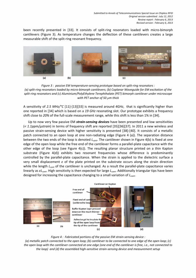
been recently presented in [33]. It consists of split‐ring resonators loaded with micro‐bimorph cantilevers (Figure 3). As temperature changes the deflection of these cantilevers creates a large measurable shift of the split‐ring resonant frequency.
(a) (b) (c)
Figure 3 : passive EM temperature‐sensing prototype based on split‐ring resonators :
(a) split‐ring resonators loaded by micro‐bimorph cantilevers; (b) Coplanar Waveguide for EM excitation of the split‐ring resonators and (c) Aluminium/PolyEthylene Terephthalate (PET) bimorph cantilever under microscope
with PET anchor of 50 m thick
A sensitivity of 2.5 MHz/°C [11]‐[13][33] is measured around 4GHz, that is significantly higher than one reported in [34] which is based on a 19 GHz resonating slot. Our prototype exhibits a frequency shift close to 20% of the full‐scale measurement range, while this shift is less than 1% in [34].
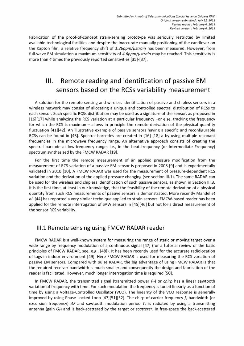
Up to now very few passive EM strain‐sensing devices have been presented and low sensitivities (< 1.1ppm/µstrain) in terms of frequency shift are reported [35][36][37]. In 2011 a new wireless and passive strain‐sensing device with higher sensitivity is presented [38]‐[40]. It consists of a metallic patch connected to an open loop at one non‐radiating edge (Figure 4 (a)). The separation distance between the two ends of the loop is denoted Lcant. The cantilever shown in Figure 4(b) is fixed at one edge of the open loop while the free end of the cantilever forms a parallel‐plate capacitance with the other edge of the loop (see Figure 4(c)). The resulting planar structure printed on a thin Kapton substrate (Figure 4(d)) exhibits two resonant frequencies whose difference is predominantly controlled by the parallel‐plate capacitance. When the strain is applied to the dielectric surface a very small displacement ε of the plate printed on the substrate occurs along the strain direction while the length Lcant of the cantilever is unchanged. As a result the parallel‐plate capacitance varies linearly as εLcant. High sensitivity is then expected for large Lcant. Additionally triangular tips have been designed for increasing the capacitance changing to a small variation of Lcant.
(c) (d)
Figure 4 : Fabricated portions of the passive EM strain‐sensing device :
(a) metallic patch connected to the open loop; (b) cantilever to be connected to one edge of the open loop; (c) the open loop with the cantilever connected at one edge (one end of the cantilever is free, i.e., not connected to
the loop) and (d) the assembled high‐sensitive strain‐sensing device and measurement setup
Submitted to Annals of Telecommunications Special Issue on Chipless RFID Original version submitted : July 12, 2012
Review report : February 6, 2013 Revised version : February 6, 2013
Fabrication of the proof‐of‐concept strain‐sensing prototype was seriously restricted by limited available technological facilities and despite the inaccurate manually positioning of the cantilever on the Kapton film, a relative frequency shift of 1.26ppm/µstrain has been measured. However, from full‐wave EM simulation a maximum sensitivity of 4.6ppm/µstrain may be reached. This sensitivity is more than 4 times the previously reported sensitivities [35]‐[37].
III. Remote reading and identification of passive EM
sensors based on the RCSs variability measurement
A solution for the remote sensing and wireless identification of passive and chipless sensors in a wireless network may consist of allocating a unique and controlled spectral distribution of RCSs to each sensor. Such specific RCSs distribution may be used as a signature of the sensor, as proposed in [16][17] while analyzing the RCS variation at a particular frequency –or else, tracking the frequency for which the RCS is maximum– allows in principle the remote derivation of the physical quantity fluctuation [41][42]. An illustrative example of passive sensors having a specific and reconfigurable RCSs can be found in [43]. Spectral barcodes are created in [16]‐[18] a by using multiple resonant frequencies in the microwave frequency range. An alternative approach consists of creating the spectral barcode at low‐frequency range, i.e., in the beat frequency (or Intermediate Frequency) spectrum synthesized by the FMCW RADAR [19].
For the first time the remote measurement of an applied pressure modification from the measurement of RCS variation of a passive EM sensor is proposed in 2008 [9] and is experimentally validated in 2010 [10]. A FMCW RADAR was used for the measurement of pressure‐dependent RCS variation and the derivation of the applied pressure changing (see section III.1). The same RADAR can be used for the wireless and chipless identification of such passive sensors, as shown in Section III.3. It is the first time, at least in our knowledge, that the feasibility of the remote derivation of a physical quantity from such RCS measurements of passive sensors is demonstrated. More recently Mandel et al. [44] has reported a very similar technique applied to strain sensors. FMCW‐based reader has been applied for the remote interrogation of SAW sensors in [45][46] but not for a direct measurement of the sensor RCS variability.
III.1 Remote sensing using FMCW RADAR reader FMCW RADAR is a well‐known system for measuring the range of static or moving target over a wide range by frequency modulation of a continuous signal [47] (for a tutorial review of the basic principles of FMCW RADAR, see, e.g., [48]). It has been recently used for the accurate radiolocation of tags in indoor environment [49]. Here FMCW RADAR is used for measuring the RCS variation of passive EM sensors. Compared with pulse RADAR, the big advantage of using FMCW RADAR is that the required receiver bandwidth is much smaller and consequently the design and fabrication of the reader is facilitated. However, much longer interrogation time is required [50].
In FMCW RADAR, the transmitted signal (transmitted power PT) or chirp has a linear sawtooth variation of frequency with time. For such modulation the frequency is tuned linearly as a function of time by using a Voltage‐Controlled Oscillator (VCO). The linearity of the VCO response is generally improved by using Phase Locked Loop [47][51][52]. The chirp of carrier frequency f, bandwidth (or
excursion frequency) F and sawtooth modulation period TR is radiated by using a transmitting antenna (gain GT) and is back‐scattered by the target or scatterer. In free‐space the back‐scattered
Submitted to Annals of Telecommunications Special Issue on Chipless RFID Original version submitted : July 12, 2012
Review report : February 6, 2013 Revised version : February 6, 2013
signal or echo consists of an attenuated replica of the chirp delayed by the two‐way propagation
delay where R designates the range and c denotes the celerity of light. The instantaneous
frequency difference between the chirp and its delayed replica is constant and given by . In
order to measure this difference and deriving the range R the echo received by the RADAR receiving antenna (Gain GR) is mixed with the transmitted chirp (homodyne principle). An Analog‐to‐Digital conversion and Fast Fourier Transform by Hamming windowing at the mixer output signal are finally performed for obtaining the beat frequency –or Intermediate Frequency– spectrum.
A millimeter‐wave carrier frequency for the FMCW RADAR may be preferred to a lower frequency. As a matter of fact, higher frequencies allow for reducing the sensor and antenna sizes and/or designing directional (high gain) antennas for beamforming, multi‐beam (for increasing interrogation beam width) or beam‐steering RADAR reader. Moreover, higher frequency improves the sensor immunity to objects located at its vicinity by increasing the electrical length separation distance to them. Therefore, the antenna impedance matching will be not significantly modified by various out‐door or indoor environments. Additionally using millimeter‐wave carrier frequency offers high bandwidth : as range resolution scales as , higher bandwidth enables spread‐spectrum
for identification of greater number of sensors in a wireless network (see section III.3). Note that the free space attenuation at frequency f2 > f1 is times higher than one at frequency f1. For this
reason one may prefer a priori a lower frequency carrier. However, assuming that the transmitted Effective Isotropic Radiated Power (EIRP), receiving antenna GR and received back‐scattered power
are identical at frequencies f1 and f2, the reading range R1 at f1 and R2 at f2 are the same when
interrogating a scatterer of given surface S. As a matter of fact, since in free‐
space [53] one deduces that with and , under
physical optics approximation (i.e., assuming that the size of the scatterer is large compared to wavelength at f1 < f2) and consequently . From all these considerations a millimeter‐wave
frequency (around 30GHz) has been chosen as the carrier of the FMCW RADAR for the wireless reading and identification of passive sensors. Note however that the tuning sensitivity of the VCO at millimeter‐wave frequency is typically around few tens of MHz/V, while at low‐frequency (UHF band) it is one order of magnitude higher. Consequently the control of the VCO output frequency is less challenging at lower frequency. Moreover specific power limitation restrictions in millimeter‐wave frequency ranges (i.e., the maximum EIRP in outdoor and indoor environments) may exist but are not considered in the present review paper.
In the proof‐on‐concept experiment dated on 2010 [10], a millimeter‐wave FMCW RADAR
operating at f=29,45GHz (F = 650 MHz, TR=1ms, PT =13dBm=20mW, GT=14dB and GR=14dB) is used for the remote derivation of applied pressure from the measurement of the RCS of passive sensor. Such sensor was composed of an antenna (Gain GA=20dB at the carrier frequency) connected to a 50‐
coaxial cable of physical length L=1m and relative permittivity r =1,7, which is in turn connected to one port of the pressure EM sensing device reported in [1] and briefly described in section III.1. This cable could be replaced by a millimeter‐wave delay line providing a propagation delay of
at the carrier frequency over a 2% bandwidth. The other port of the sensing device
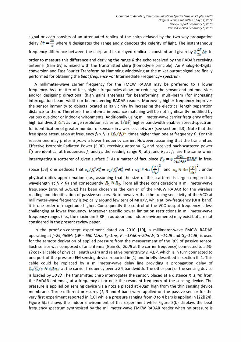
is loaded by 50 . The transmitted chirp interrogates the sensor, placed at a distance R=1,4m from the RADAR antennas, at a frequency at or near the resonant frequency of the sensing device. The pressure is applied on sensing device via a nozzle placed at 40μm high from the thin sensing device membrane. Three different pressures (1, 3 and 4 bars) were applied on the passive sensor for the very first experiment reported in [10] while a pressure ranging from 0 to 4 bars is applied in [22][24]. Figure 5(a) shows the indoor environment of this experiment while Figure 5(b) displays the beat frequency spectrum synthesized by the millimeter‐wave FMCW RADAR reader when no pressure is
Submitted to Annals of Telecommunications Special Issue on Chipless RFID Original version submitted : July 12, 2012
Review report : February 6, 2013 Revised version : February 6, 2013
applied. As expected this spectrum exhibits two spikes or echoes at specific beat frequencies: at the
beat frequency , the echo level corresponds to the backscattering from
the sensor antenna while the second echo level occurring at a beat frequency
is associated with the reflection of the millimeter wave on the
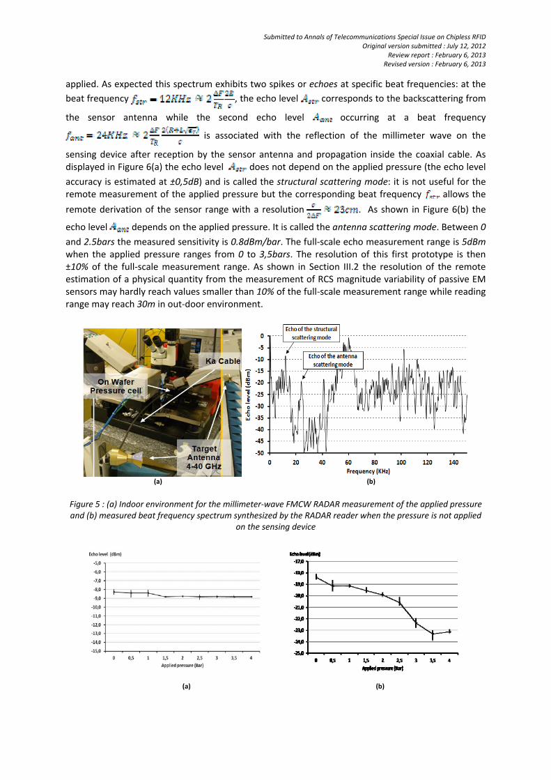
sensing device after reception by the sensor antenna and propagation inside the coaxial cable. As displayed in Figure 6(a) the echo level does not depend on the applied pressure (the echo level
accuracy is estimated at ±0,5dB) and is called the structural scattering mode: it is not useful for the remote measurement of the applied pressure but the corresponding beat frequency allows the
remote derivation of the sensor range with a resolution . As shown in Figure 6(b) the
echo level depends on the applied pressure. It is called the antenna scattering mode. Between 0
and 2.5bars the measured sensitivity is 0.8dBm/bar. The full‐scale echo measurement range is 5dBm when the applied pressure ranges from 0 to 3,5bars. The resolution of this first prototype is then ±10% of the full‐scale measurement range. As shown in Section III.2 the resolution of the remote estimation of a physical quantity from the measurement of RCS magnitude variability of passive EM sensors may hardly reach values smaller than 10% of the full‐scale measurement range while reading range may reach 30m in out‐door environment.
(a) (b)
Figure 5 : (a) Indoor environment for the millimeter‐wave FMCW RADAR measurement of the applied pressure and (b) measured beat frequency spectrum synthesized by the RADAR reader when the pressure is not applied
on the sensing device
(a) (b)
Submitted to Annals of Telecommunications Special Issue on Chipless RFID Original version submitted : July 12, 2012
Review report : February 6, 2013 Revised version : February 6, 2013
Figure 6: Measured echo level of passive EM pressure sensor versus applied pressure at two characteristic beat frequencies: (a) at the beat frequency fstr of the structural scattering mode and
(b) at the beat frequency fant of the antenna scattering mode
When a pressure is applied on the membrane of the sensing device, the RCS of antenna‐scattering‐mode is varied, received back‐scattered power PR changes and as a result echo level is modified.
The measurement of this modification allows, at least in principle, the remote estimation of the applied pressure variation. This summarizes the wireless reading principle based on the FMCW RADAR measurement of sensor‐RCS variation. Moreover the difference between the two
measured beat frequencies (due to distinct time‐arrivals of structural‐ and antenna‐scattering‐modes) allows the remote derivation of the transmission line electrical length: by allocating a specific length at each passive EM sensor and using the FMCW RADAR reader for measuring the resulting difference , passive sensors could be remotely identified. The electrical length of the
transmission line can then be used as specific signature for the passive EM sensor and may be wirelessly detected by the same FMCW RADAR used for remote sensing. This identification technique will be discussed in Section III.3. The remote measurement of temperature based on the RCS variability of micro‐fluidics scatterer is
presented for the first time in 2011 [14][15]. Liquid metal is used to dynamically modify the number
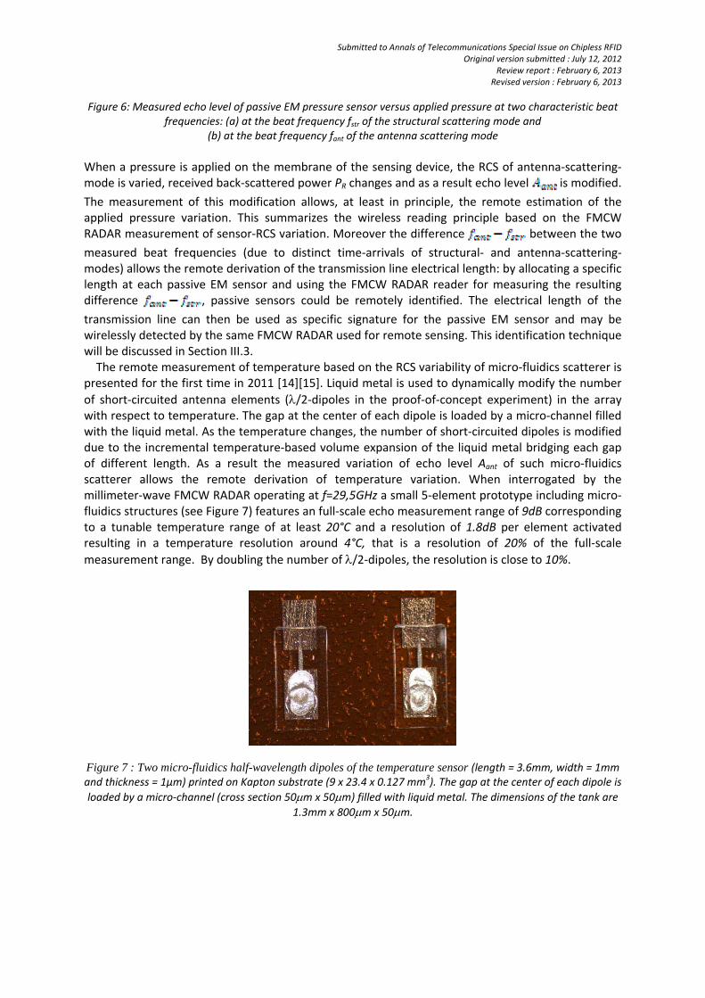
of short‐circuited antenna elements (/2‐dipoles in the proof‐of‐concept experiment) in the array with respect to temperature. The gap at the center of each dipole is loaded by a micro‐channel filled with the liquid metal. As the temperature changes, the number of short‐circuited dipoles is modified due to the incremental temperature‐based volume expansion of the liquid metal bridging each gap of different length. As a result the measured variation of echo level Aant of such micro‐fluidics scatterer allows the remote derivation of temperature variation. When interrogated by the millimeter‐wave FMCW RADAR operating at f=29,5GHz a small 5‐element prototype including micro‐fluidics structures (see Figure 7) features an full‐scale echo measurement range of 9dB corresponding to a tunable temperature range of at least 20°C and a resolution of 1.8dB per element activated resulting in a temperature resolution around 4°C, that is a resolution of 20% of the full‐scale
measurement range. By doubling the number of /2‐dipoles, the resolution is close to 10%.
Figure 7 : Two micro-fluidics half-wavelength dipoles of the temperature sensor (length = 3.6mm, width = 1mm and thickness = 1µm) printed on Kapton substrate (9 x 23.4 x 0.127 mm3). The gap at the center of each dipole is
loaded by a micro‐channel (cross section 50m x 50m) filled with liquid metal. The dimensions of the tank are
1.3mm x 800m x 50m.
Submitted to Annals of Telecommunications Special Issue on Chipless RFID Original version submitted : July 12, 2012
Review report : February 6, 2013 Revised version : February 6, 2013
III.2 Full‐scale RCS measurement range and reading range
Following the proposed remote sensing technique based on RCS‐variability measurement, the
passive EM sensor yields a full‐scale echo measurement range given by = (in
dB)[or equivalently a full scale RCS range 2 – 1 (in dB)] corresponding to a tunable physical
quantity range of . For a given RADAR‐to‐sensor link separation distance R, reaches its maximum value when A1 is close to the noise level Anoise (but is still measurable) and when
A2 is the echo level when the sensor antenna is short‐circuited (RCS is then given by [53]).
Consequently the order of magnitude of the maximum achievable full‐scale measurement range
is given by . The higher the sensor antenna gain at carrier frequency the larger the full‐
scale echo range. For illustration purpose consider a passive scatterer composed of a horn antenna
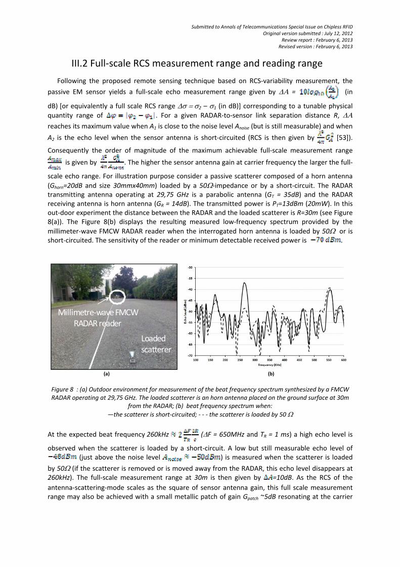
(Ghorn=20dB and size 30mmx40mm) loaded by a 50‐impedance or by a short‐circuit. The RADAR transmitting antenna operating at 29,75 GHz is a parabolic antenna (GT = 35dB) and the RADAR receiving antenna is horn antenna (GR = 14dB). The transmitted power is PT=13dBm (20mW). In this out‐door experiment the distance between the RADAR and the loaded scatterer is R=30m (see Figure 8(a)). The Figure 8(b) displays the resulting measured low‐frequency spectrum provided by the
millimeter‐wave FMCW RADAR reader when the interrogated horn antenna is loaded by 50 or is short‐circuited. The sensitivity of the reader or minimum detectable received power is .
Loadedscatterer
Millimetre‐waveFMCW RADAR reader
(a) (b)
Figure 8 : (a) Outdoor environment for measurement of the beat frequency spectrum synthesized by a FMCW RADAR operating at 29,75 GHz. The loaded scatterer is an horn antenna placed on the ground surface at 30m
from the RADAR; (b) beat frequency spectrum when:
—the scatterer is short‐circuited; ‐ ‐ ‐ the scatterer is loaded by 50
At the expected beat frequency 260kHz (F = 650MHz and TR = 1 ms) a high echo level is
observed when the scatterer is loaded by a short‐circuit. A low but still measurable echo level of (just above the noise level ) is measured when the scatterer is loaded
by 50 (if the scatterer is removed or is moved away from the RADAR, this echo level disappears at 260kHz). The full‐scale measurement range at 30m is then given by =10dB. As the RCS of the
antenna‐scattering‐mode scales as the square of sensor antenna gain, this full scale measurement range may also be achieved with a small metallic patch of gain Gpatch ~5dB resonating at the carrier
Submitted to Annals of Telecommunications Special Issue on Chipless RFID Original version submitted : July 12, 2012
Review report : February 6, 2013 Revised version : February 6, 2013
frequency (size~5mmx5mm) is placed at a distance . As the accuracy on the echo
level measurement is A~1dB, the resolution is low (approximately 10%). An alternative
solution for improving the measurement resolution would consist of tracking in the beat frequency spectrum the frequency at which the RCS reaches its maximum value as the physical quantity varies [23][42].
III.3 Remote identification of passive EM sensors using FMCW RADAR reader
The FMCW‐RADAR reader used for the remote reading of passive sensors can also be utilized for identification purposes. When the passive sensor is composed of an antenna connected to a transmission line (or delay line) which loads in turn the sensing device, the measurement of the difference between the beat frequencies of the antenna‐scattering‐mode and structural‐
scattering‐mode allows the remote estimation of the transmission line electrical length (or
propagation delay), as mentioned in section III.2. By allocating a specific electrical length (or delay) to each sensor in a wireless network, this simple measurement may be used, at least in principle, for identification purpose. In the proof‐of‐concept experiment reported [19] the sensor is viewed as a passive scatterer composed of an antenna connected to multiple transmission lines (or delay‐lines),
each being loaded by various impedances. All transmission lines used in this experiment are 50‐
coaxial lines filled with dielectric material of relative permittivity r=1,7 and having 2dB/m of losses).
Antenna 1 + 0.30 m
coaxial cable
Antenna 2 + 0.75 m
coaxial cable+
Splitter+ 0.75 m
coaxial cableRadar horn antennas
Antenna 2
Antenna 1
FMCWRADAR
R1
R2
Z1
L1
Antenna 1
Splitter
Z2
Z3
L2
Antenna 2
L3
(a) (b)
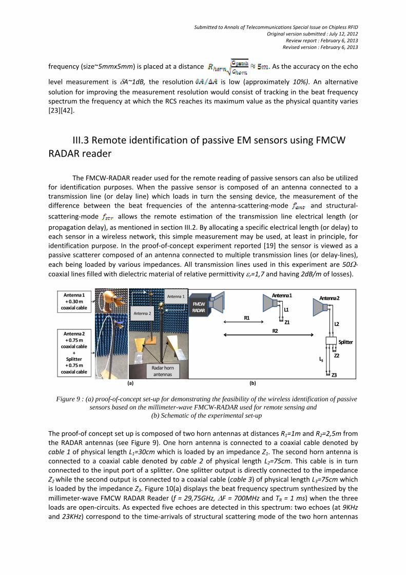
Figure 9 : (a) proof-of-concept set-up for demonstrating the feasibility of the wireless identification of passive
sensors based on the millimeter-wave FMCW-RADAR used for remote sensing and (b) Schematic of the experimental set-up
The proof‐of concept set up is composed of two horn antennas at distances R1=1m and R2=2,5m from the RADAR antennas (see Figure 9). One horn antenna is connected to a coaxial cable denoted by cable 1 of physical length L1=30cm which is loaded by an impedance Z1. The second horn antenna is connected to a coaxial cable denoted by cable 2 of physical length L2=75cm. This cable is in turn connected to the input port of a splitter. One splitter output is directly connected to the impedance Z2 while the second output is connected to a coaxial cable (cable 3) of physical length L3=75cm which is loaded by the impedance Z3. Figure 10(a) displays the beat frequency spectrum synthesized by the
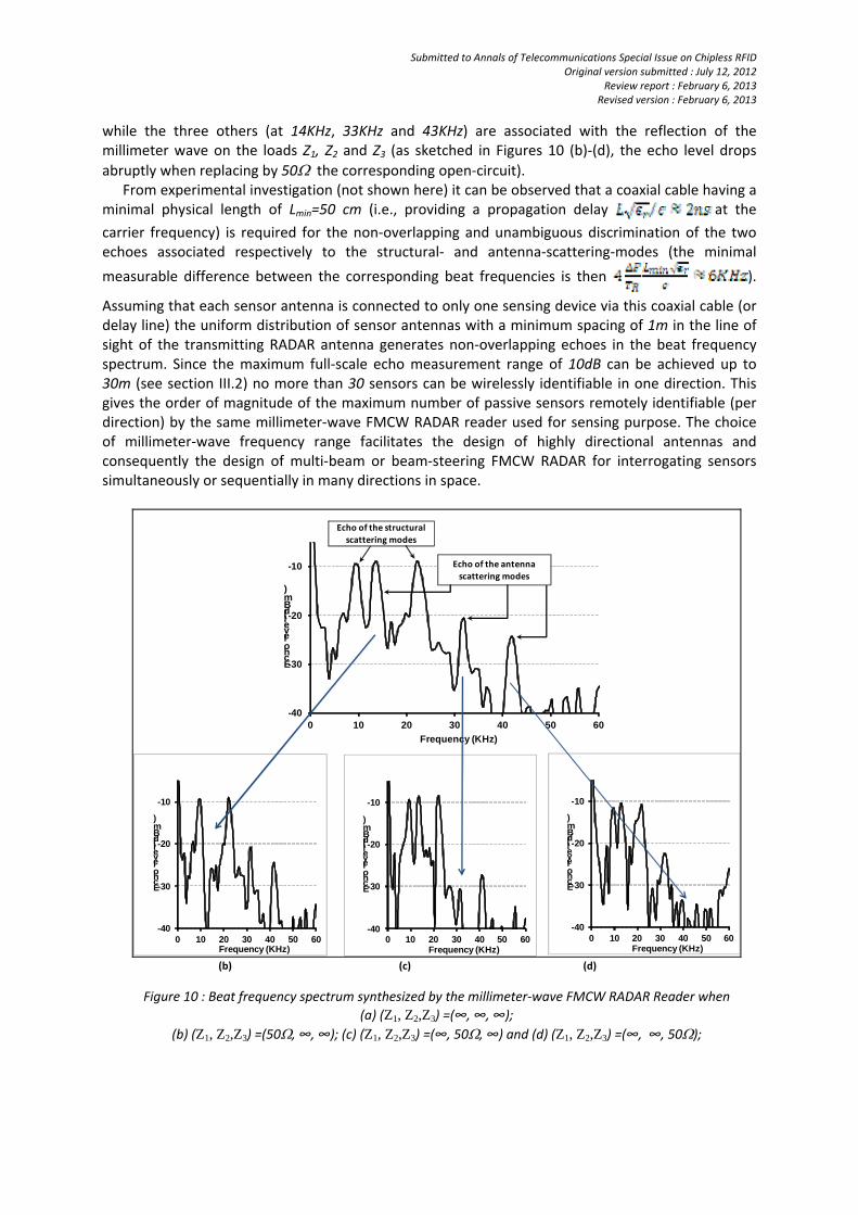
millimeter‐wave FMCW RADAR Reader (f = 29,75GHz, F = 700MHz and TR = 1 ms) when the three loads are open‐circuits. As expected five echoes are detected in this spectrum: two echoes (at 9KHz and 23KHz) correspond to the time‐arrivals of structural scattering mode of the two horn antennas
Submitted to Annals of Telecommunications Special Issue on Chipless RFID Original version submitted : July 12, 2012
Review report : February 6, 2013 Revised version : February 6, 2013
while the three others (at 14KHz, 33KHz and 43KHz) are associated with the reflection of the millimeter wave on the loads Z1, Z2 and Z3 (as sketched in Figures 10 (b)‐(d), the echo level drops
abruptly when replacing by 50 the corresponding open‐circuit). From experimental investigation (not shown here) it can be observed that a coaxial cable having a minimal physical length of Lmin=50 cm (i.e., providing a propagation delay at the
carrier frequency) is required for the non‐overlapping and unambiguous discrimination of the two echoes associated respectively to the structural‐ and antenna‐scattering‐modes (the minimal
measurable difference between the corresponding beat frequencies is then ).
Assuming that each sensor antenna is connected to only one sensing device via this coaxial cable (or delay line) the uniform distribution of sensor antennas with a minimum spacing of 1m in the line of sight of the transmitting RADAR antenna generates non‐overlapping echoes in the beat frequency spectrum. Since the maximum full‐scale echo measurement range of 10dB can be achieved up to 30m (see section III.2) no more than 30 sensors can be wirelessly identifiable in one direction. This gives the order of magnitude of the maximum number of passive sensors remotely identifiable (per direction) by the same millimeter‐wave FMCW RADAR reader used for sensing purpose. The choice of millimeter‐wave frequency range facilitates the design of highly directional antennas and consequently the design of multi‐beam or beam‐steering FMCW RADAR for interrogating sensors simultaneously or sequentially in many directions in space.
-40
-30
-20
-10
0 10 20 30 40 50 60
Echo level (dBm)
Frequency (KHz)
Echo of the structuralscattering modes
Echo of the antennascattering modes
-40
-30
-20
-10
0 10 20 30 40 50 60
Echo level (dBm)
Frequency (KHz)
-40
-30
-20
-10
0 10 20 30 40 50 60
Echo level (dBm)
Frequency (KHz)
-40
-30
-20
-10
0 10 20 30 40 50 60
Echo level (dBm)
Frequency (KHz) (b) (c) (d)
Figure 10 : Beat frequency spectrum synthesized by the millimeter‐wave FMCW RADAR Reader when
(a) (Z1, Z2,Z3) =(∞, ∞, ∞);
(b) (Z1, Z2,Z3) =(50, ∞, ∞); (c) (Z1, Z2,Z3) =(∞, 50, ∞) and (d) (Z1, Z2,Z3) =(∞, ∞, 50);

Submitted to Annals of Telecommunications Special Issue on Chipless RFID Original version submitted : July 12, 2012
Review report : February 6, 2013 Revised version : February 6, 2013
IV. Conclusion
The use of a millimeter‐wave FMCW Radar reader for both the wireless reading and identification of passive EM sensors has been presented in this review paper. It is shown that the wireless measurement of various physical quantities is possible from the analysis of the RADAR Cross Sections variability of passive electromagnetic sensors. Additionally the same FMCW RADAR can be used for identifying the passive sensors in a wireless network. For transmitted power of few tens of mW the proposed system allows achieving reading range of some ten meters for small sensor antennas (size~1cmx1cm). In a given direction few tens of sensors can be identified. However, the measurement resolution is poor (typically 10 % of the full‐scale measurement range). An alternative solution would consist of tracking in the beat frequency spectrum the frequency at which the RCS reaches its maximum value as the physical quantity varies [23][42]. This solution, under investigation, may achieve higher measurement resolution while not significantly alters the reading range. Acknowledgements : the author wish to thank the two following institutions for financial support:
the French Radioactive Waste Management Agency (ANDRA) through the contract N° 045985 and
the Pole de Competitivité Aéronautique, Espace et Systèmes Embarqués (AESE) through the project
Système Autonome Communicant En Réseau (SACER).
Submitted to Annals of Telecommunications Special Issue on Chipless RFID Original version submitted : July 12, 2012
Review report : February 6, 2013 Revised version : February 6, 2013
References
[1] JATLAOUI, M., PONS, P., AUBERT, H.: Radio‐Frequency pressure transducer. European Microwave Conference, München, Germany, pp. 983‐986 (2007). [2] MCGRATH, M., SABOUNI, R., PHAM, A.: Development of nano‐based resonator gas sensors for wireless sensing systems. Proceedings of the SPIE, vol. 5593, No 1, pp. 62‐72 (2004). [3] CHUANG, J., THOMSON, D.J., BRIDGES, G.E.: Embeddable wireless strain sensor based on resonant RF cavities. Review of Scientific Instruments, DOI: 10.1063/1.2051808. [4] BUFF, W., KLETT, S., RUSKO, M., EHRENPFORDT, J., GOROLI, M.: Passive remote sensing for temperature and pressure using SAW resonator devices. IEEE Transactions on Ultrasonics, Ferroelectrics and Frequency Control, vol. 45, No. 5, pp. 1388 – 1392 (1998). [5] VARADAN, V.K., TEO, P.T., JOSE, K.A., VARADAN, V.V.: Design and development of a smart wireless system for passive temperature sensors. Smart Materials and Structures, vol. 9, No 4, pp. 379‐388 (2000). [6] POHL, A.: A Review of Wireless SAW Sensors. IEEE Transactions on Ultrasonics, Ferroelectrics, and Frequency Control, vol. 47, No. 2, pp.317‐332 (2000). [7] PEREIRA, M., LAD, R.J., DAVULIS, P., CANABAL, A., MOONLIGHT, T., MOULZOLF, S., FRANKEL, D.J., POLLARD, T., McCANN, D., DUDZIK, E., ABEDI, A., HUMMELS, D., BERNHARDT, G., Wireless Acoustic Wave Sensors and Systems for Harsh Environment Applications. Wireless Sensors and Sensor Networks Conference, Phoenix, USA, pp.41‐44 (2011). [8] PONS, P., AUBERT, H., MENINI, P., TENTZERIS, M.: Electromagnetic transduction for wireless passive sensors. Proc. Eurosensors XXVI, Procedia Engineering 47, 9‐12 september 2012, Kraków, Poland, pp.1474–1483 (2012). [9] JATLAOUI, M., CHEBILA, F., PONS, P., AUBERT, H.: Pressure Sensing Approach Based on Electromagnetic Transduction Principle. Asia Pacific Microwave Conference, Hong Kong and Macao, China (2008). [10] CHEBILA, F., JATLAOUI, M., PONS, P., AUBERT, H.: Pressure Measurement from the RADAR Interrogation of Passive Sensors. IEEE International Symposium on Antennas Propagat., Toronto, Ontario, Canada (2010). [11] THAI, T.‐T., CHEBILA, F., JATLAOUI, M., PONS, P., AUBERT, H., DEJEAN, G.R., TENTZERIS, M.M., PLANA, R.: A Novel Passive Ultrasensitive RF Temperature Transducer for Remote Sensing and Identification utilizing RADAR Cross Sections Variability. IEEE Antennas and Propagation Symposium, Toronto, Ontario, Canada (2010). [12] THAI, T.‐T., CHEBILA, F., JATLAOUI, M., PONS, P., AUBERT, H., DEJEAN, G.R., TENTZERIS, M., PLANA, R.: Design and Development of a Millimetre‐wave Novel Passive Ultrasensitive Temperature Transducer for Remote Sensing and Identification. European Microwave Week, Paris, France (2010).
Submitted to Annals of Telecommunications Special Issue on Chipless RFID Original version submitted : July 12, 2012
Review report : February 6, 2013 Revised version : February 6, 2013
[13] T.THAI, M.‐M.JATLAOUI, F.CHEBILA, H.AUBERT, P.PONS, G.‐R.DEJEAN, M.‐M. TENTZERIS, R.PLANA,” Design and Development of a Novel Passive Wireless Ultrasensitive RF Temperature Transducer for Remote Sensing,” IEEE Sensors Journal, vol. 12, Issue 9, pp.2756‐2766 (2012). [14] TRAILLE, A., BOUAZIZ, S., AUBERT, H., PONS, P., TENTZERIS, M.: A Novel Wireless Passive Temperature Sensor Utilizing Microfluidic Principles in Millimeter‐Wave Frequencies. IEEE sensors Conference, Limerick, Ireland, pp 524 – 525 (2011). [15] TRAILLE, A., BOUAZIZ, S., PINON, S., PONS, P., AUBERT, H., BOUKABACHE, A., TENTZERIS, M.: A Wireless Passive RCS‐based Temperature Sensor using Liquid Metal and Microfluidics Technologies. European Microwave Week, Manchester, UK (2011). [16] JALALY, I., ROBERTSON, D.: Capacitively‐tuned split microstrip resonators for RFID barcodes. Eur. Microw. Conf., Paris, France, vol. 2, pp. 4–7 (2005). [17] McVAY, J., HOORFAR, A., ENGHETA, N.: Space‐filling curve RFID tags. IEEE Radio Wireless Symp., San Diego, CA, pp. 199–200 (2006). [18] PRERADOVIC, S., BALBIN, I., KARMAKAR, N.C., SWIEGERS, G.: Multiresonator‐Based Chipless RFID System for Low‐Cost Item Tracking. IEEE Transactions on Microwave Theory and Techniques, vol. 57, No. 5, pp. 1411‐1419 (2009). [19] JATLAOUI, M., CHEBILA, F., BOUAZIZ, S., PONS, P., AUBERT, H.: Original Identification technique of passive EM Sensors using Loaded Transmission Delay Lines. European Microwave Week, Paris, France (2010). [20] JATLAOUI, M., CHEBILA, F., GMATI, I., PONS, P., AUBERT, H.: New Electromagnetic Transduction Micro‐sensor Concept For Passive Wireless Pressure Monitoring Application. Transducers, 15th International Conference on Solid‐State Sensors, Actuators and Microsystems, Denver, Colorado, USA, pp. 1742‐1745 (2009).
[21] JATLAOUI, M., PONS, P., AUBERT, H.: Pressure Micro‐sensor based on Radio‐Frequency Transducer. IEEE International Microwave Symposium, Atlanta, Georgia, USA, pp. 1203‐1206 (2008). [22] JATLAOUI, M., CHEBILA, F., PONS, P., AUBERT, H.: Working Principle Description of the Wireless Passive EM Transduction Pressure Sensor. The European Physical Journal ‐ Applied Physics, 56, 13702 (2011). [23] JATLAOUI, M., CHEBILA, F., PONS, P., AUBERT, H.: Wireless Interrogation Techniques for a Passive Pressure Micro‐sensor using an EM Transducer. European Microwave Week, Nuova Fiera di Roma, Rome, Italy (2009). [24] JATLAOUI, M., CHEBILA, F., IDDA, T., PONS, P., AUBERT, H.: Phenomenological theory and experimental characterizations of passive wireless EM pressure micro‐sensor prototype. IEEE Conference on Sensors, Waikaloa, Hawaï, USA (2010). [25] HALLIL, H., CHEBILA, F., MENINI, P., AUBERT, H.: Feasibility of Passive Gas Sensor Based on Whispering Gallery Modes and its RADAR Interrogation: Theoretical and Experimental Investigations. Sensors & Transducers journal, vol. 116, No 5, pp.38‐48 (2010).
Submitted to Annals of Telecommunications Special Issue on Chipless RFID Original version submitted : July 12, 2012
Review report : February 6, 2013 Revised version : February 6, 2013
[26] CROS, D., GUILLON, P.: Whispering Gallery Dielectric Resonator Modes for W‐Band devices. IEEE Transactions on Microwave Theory and Techniques, Vol. 38, No 11, pp. 1667‐1671 (1990). [27] TOBAR, M., IVANOV, E.N., BLONDY, P., CROS, D., GUILLON, P.: High‐Q Whispering Gallery Travelling Wave Resonators for Oscillator Frequency Stabilization. IEEE Transactions on Ultrasonics, Ferroelectrics, and Frequency Control, vol. 47, No 2, pp. 421‐425 (2000). [28] HALLIL, H., MÉNINI, P., AUBERT, H.: Novel Microwave Gas Sensor Using Dielectric Resonator with SnO2 Sensitive Layer. Eurosensors, Lausanne, Switzerland (2009). [29] HALLIL, H., MÉNINI, P., AUBERT, H.: New microwave gas detector using dielectric resonator based on a Whispering‐Gallery‐Mode. European Microwave Week, Nuova Fiera di Roma, Rome, Italy (2009). [30] HALLIL, H., MÉNINI, P., AUBERT, H.: Novel Millimeter‐Wave Gas Sensor Using Dielectric Resonator with sensitive layer on TiO2. IEEE Conference on Sensors, Christchurch, New Zealand (2009). [31] HALLIL, H., CHEBILA, F., MENINI, P., PONS, P., AUBERT, H.: Feasibility of Wireless Gas Detection with an FMCW RADAR Interrogation of Passive RF Gas Sensor. IEEE Conference on Sensors, Waikaloa, Hawaï, USA (2010). [32] AUBERT, H., HALLIL, H., MENINI, P. : Système de mesure de la température à très haute sensibilité basé sur les modes de galerie, procédé, produit programme d’ordinateur et médium de stockage correspondants, Patent Pending FR1160896, Nov. 29, 2011. [33] THAI, T.‐T., JATLAOUI, M., AUBERT, H., PONS, P., DEJEAN, G.R., TENTZERIS, PLANA, R.: A Novel Passive Wireless Ultrasensitive Temperature RF Transducer for Remote Sensing. IEEE International Microwave Symposium, Anaheim, California, USA, pp. 473‐476 (2010). [34] SCOTT, S., PEROULIS, D.: A capacitively‐loaded MEMS slot element for wireless temperature sensing of up to 300oC. IEEE International Microwave Symposium, Boston, MA, pp. 1161‐1164 (2009). [35] TATA, U., HUANG, H., CARTER, R., CHIAO, J.C.: Exploiting a patch antenna for strain measurements. Measurement Science and Technology, vol. 20(1), pp. 1‐7 (2009). [36] DALIRI, A., GALEHDAR, A., JOHN, S., ROWE,W., GHORBANI, K.: Circular Microstrip Patch Antenna Strain Sensor for Wireless Structural Health Monitorin. Proceedings of the World Congress on Engineering, vol. II, London, U.K. (2010). [37] MELIK, R., UNAL, E., PERKGOZ, N.K., PUTTLITZ, C., DEMIR, H.V.: Metamaterial‐based wireless strain sensors. Applied Physics Letters, vol. 95(1). DOI: 10.1063/1.3162336 (2009). [38] THAI, T.‐T., AUBERT, H., PONS, P., TENTZERIS, M., PLANA, R.: Design of a Highly Sensitive Wireless and Passive RF Strain Transducer. IEEE International Microwave Symposium, Baltimore, Maryland, USA (2011). [39] THAI, T.‐T., AUBERT, H., PONS, P., DEJEAN, G.R., TENTZERIS, M., PLANA, R.: Newly Developed Radio Frequency Wireless Passive Highly Sensitive Strain Transducer. IEEE sensors Conference, Limerick, Ireland, pp. 211‐214 (2011).
Submitted to Annals of Telecommunications Special Issue on Chipless RFID Original version submitted : July 12, 2012
Review report : February 6, 2013 Revised version : February 6, 2013
[40] AUBERT, H., THAI, T.‐T., PONS, P. : Capteur de contrainte. Patent pending FR1154781, May 31, 2011. [41] JATLAOUI, M., CHEBILA, F., PONS, P., AUBERT, H.: New Micro‐sensors Identification Techniques Based on Reconfigurable Multi‐band Scatterers. Asia‐Pacific Microwave Conference, Singapore (2009). [42] AUBERT, H., PONS, P., CHEBILA, F., JATLAOUI, M. : Measurement Device Comprising an Electromagnetic Diffuser, Patent WO 2010/136388, May 29, 2009. [43] CHEBILA, F., JATLAOUI, M., PONS, P., AUBERT, H.: Reconfigurable Multi‐band Scatterers for Micro‐sensors Identification. IEEE International Symposium on Antennas Propagat., Charleston, South Carolina, USA (2009). [44] MANDEL, C., SCHÜßLER, M., JAKOBY, R.: A Wireless Passive Strain Sensor. IEEE sensors Conference, Limerick, Ireland, pp. 2007‐2010 (2011). [45] DROIT, C., MARTIN, G., BALLANDRAS, S., FRIEDT, J.‐M.: A frequency modulated wireless interrogation system exploiting narrowband acoustic resonator for remote physical quantity measurement. Review of scientific instruments, DOI: 10.1063/1.3402286. [46] STELZER, A., SCHEIBLHOFER, S., SCHUSTER, S., TEICHMANN, R.: Wireless sensor marking and temperature measurement with SAW‐identification tags. Measurement, vol. 41, pp.579–588 (2008). [47] STOVE, A.: Linear FMCW RADAR techniques. IEE Proceedings F, vol. 139, No 5, pp. 343‐350 (1992). [48] GRIFFITHS, H.D.: New Ideas in FM RADAR. Electronics & Communication Engineering Journal, pp. 185‐194 (1990). [49] MARCACCIOLI, L., SBARRA, E., URBANI, L., GATTI, R.V., SORRENTINO, R. : An accurate indoor ranging system based on FMCW radar. IEEE Intelligent Vehicles Symposium, Baden‐Baden, Germany, pp. 981‐986 (2011). [50] KALININ V.: Passive Wireless Strain and Temperature Sensors Based on SAW Devices. IEEE sensors Conference, Vienna, Austria (2004). [51] PICHLER, M., STELZER, A., SEISENBERGER, C.: Modeling and simulation of PLL‐based frequency‐synthesizers for FMCW RADAR. IEEE International Symposium on Circuits and Systems, pp. 1540‐1543 (2008). [52] SCHEIBLHOFER, S., SCHUSTER, S., STELZER, A.: High‐Speed FMCW RADAR Frequency Synthesizer With DDS Based Linearization. IEEE Microwave and Wireless Components Letters, vol. 17, No 5, pp. 397‐399 (2007). [53] BALANIS, C.A.: Antenna Theory. John Wiley & Sons, Hoboken, New Jersey (2005).


![Hyperspectral Remote Sensing of Phytoplankton Species ...²ˆ芳.pdf · type [7]. In addition, they are also indicative of variability in phytoplankton species diversity in the ocean](https://img.dokumen.tips/doc/110x75/604b1bd50788831e2b23d1b3/hyperspectral-remote-sensing-of-phytoplankton-species-epdf-type-7.jpg)