Embed Size (px)
Citation preview


WirelessCrashCourse
Second Edition
Paul Bedell
McGraw-Hill/OsborneNew York Chicago San Francisco Lisbon
London Madrid Mexico City MilanNew Delhi San Juan Seoul Singapore
Sydney Toronto

Copyright © 2005 by The McGraw-Hill Companies, Inc. All rights reserved. Manufactured in theUnited States of America. Except as permitted under the United States Copyright Act of 1976, no partof this publication may be reproduced or distributed in any form or by any means, or stored in a data-base or retrieval system, without the prior written permission of the publisher.
0-07-158902-3
The material in this eBook also appears in the print version of this title: 0-07-145280-X.
All trademarks are trademarks of their respective owners. Rather than put a trademark symbol afterevery occurrence of a trademarked name, we use names in an editorial fashion only, and to the bene-fit of the trademark owner, with no intention of infringement of the trademark. Where such designa-tions appear in this book, they have been printed with initial caps.
McGraw-Hill eBooks are available at special quantity discounts to use as premiums and sales promo-tions, or for use incorporate training programs. For more information, please contact George Hoare,Special Sales, at [email protected] or (212) 904-4069.
TERMS OF USE
This is a copyrighted work and The McGraw-Hill Companies, Inc. (“McGraw-Hill”) and its licensorsreserve all rights in and to the work. Use of this work is subject to these terms. Except as permittedunder the Copyright Act of 1976 and the right to store and retrieve one copy of the work, you may notdecompile, disassemble, reverse engineer, reproduce, modify, create derivative works based upon,transmit, distribute, disseminate, sell, publish or sublicense the work or any part of it without McGraw-Hill’s prior consent. You may use the work for your own noncommercial and personal use;any other use of the work is strictly prohibited. Your right to use the work may be terminated if you failto comply with these terms.
THE WORK IS PROVIDED “AS IS.” McGRAW-HILL AND ITS LICENSORS MAKE NO GUAR-ANTEES OR WARRANTIES AS TO THE ACCURACY, ADEQUACY OR COMPLETENESS OFOR RESULTS TO BE OBTAINED FROM USING THE WORK, INCLUDING ANY INFORMA-TION THAT CAN BE ACCESSED THROUGH THE WORK VIA HYPERLINK OR OTHERWISE,AND EXPRESSLY DISCLAIM ANY WARRANTY, EXPRESS OR IMPLIED, INCLUDING BUTNOT LIMITED TO IMPLIED WARRANTIES OF MERCHANTABILITY OR FITNESS FOR APARTICULAR PURPOSE. McGraw-Hill and its licensors do not warrant or guarantee that the func-tions contained in the work will meet your requirements or that its operation will be uninterrupted orerror free. Neither McGraw-Hill nor its licensors shall be liable to you or anyone else for any inaccu-racy, error or omission, regardless of cause, in the work or for any damages resulting therefrom.McGraw-Hill has no responsibility for the content of any information accessed through the work.Under no circumstances shall McGraw-Hill and/or its licensors be liable for any indirect, incidental,special, punitive, consequential or similar damages that result from the use of or inability to use thework, even if any of them has been advised of the possibility of such damages. This limitation of lia-bility shall apply to any claim or cause whatsoever whether such claim or cause arises in contract, tortor otherwise.
DOI: 10.1036/007145280X

We hope you enjoy thisMcGraw-Hill eBook! If
you’d like more information about this book,its author, or related books and websites,please click here.
Professional
Want to learn more?

To Margot, Steve, Aimee, and Mark
To Ric, for always being there
And to a budding 8-year-old writer,my son Bob

ABOUT THE AUTHORPaul Bedell obtained a master of science degree in telecommunicationsmanagement, with distinction, from Chicago’s DePaul University in1994. In 1995, Bedell designed and has since taught a survey course oncellular and wireless telecommunications in the Graduate School ofComputer Science, Telecommunications, and Information Systems atDePaul University. Bedell also developed and launched an advancedwireless engineering and deployment course in spring 2004.
He began his telecommunications career in the United States ArmySignal Corps, serving in (West) Germany from 1985 to 1988, where heworked as a multichannel communications equipment operator at aremote signal site. Upon discharge in 1988, Bedell spent 5 years workingfor several Fortune 500 companies as a telecommunications analyst.
From there, he moved to the wireless industry, where he spent 5 yearsworking for three leading wireless carriers in both the cellular and PCSindustries. In those positions, Bedell worked in network planning, fixednetwork engineering, information technology network planning, and cor-porate LAN operations.
Bedell moved to Ameritech’s long-distance business unit, AmeritechCommunications, Inc. (or ACI), in 1998. He managed the implementationof ACI’s 42-node data network, supporting its new 2,500-mile Synchro-nous Optical Network (SONET) system, which spanned five midwesternstates. He also managed the installation of two voice over IP (VoIP) net-works at ACI, the first-ever VoIP networks installed Ameritech-wide.After the merger with SBC, Bedell moved into SBC product marketing inAugust 2000, managing a metro area Ethernet product known as Giga-MAN®. Bedell managed the expansion of the product into seven addi-tional states (along with the midwestern states) and oversaw thedevelopment of multiple enhancements to the product. In May 2004,Bedell began product management work supporting SBC’s Hosted IPCommunication Service, a hosted VoIP service. He can be reached [email protected].
Copyright © 2005 by The McGraw-Hill Companies, Inc. Click here for terms of use.

CONTENTSAbout the Author ivAcknowledgments xvPreface xvii
Chapter 1 Cellular Radio History and Development 1
1.1 Definition of Cellular Radio: The Cellular Concept 21.2 Cellular System Objectives 31.3 AMPS: The American Cellular Standard 41.4 AMPS Technical Specifications 61.5 The Cellular Market Structure: MSAs and RSAs 71.6 The “A” Carrier and “B” Carrier Designations 81.7 Initial Cellular Licensing 10Test Questions 11
Chapter 2 Basic Wireless Network Design and Operation 13
2.1 Frequency Reuse and Planning 142.2 Distance-to-Reuse Ratio 152.3 Call-Handoff 172.4 Maps Used in Wireless System Design 182.5 The Hexagon Grid 192.6 Fundamental Wireless System Components 21
2.6.1 The Mobile Phone 212.6.2 The Cell Base Station 232.6.3 The Backhaul Network 232.6.4 The Mobile Switching Center (MSC) 232.6.5 Interconnection to the Public Switched
Telephone Network (PSTN) and the Internet 232.7 POP Counts 24Test Questions 24
Chapter 3 The Cell Base Station 27
3.1 Overview 283.2 Criteria and Methods for Cell Placement 293.3 Selecting Cell Base Station Locations 333.4 Cell Base Station Deployment 343.5 Base Station Shelters 393.6 Cells on Wheels (COWs) 413.7 Enhancers 423.8 Microcells 443.9 Picocells and Nanocells 46Test Questions 47
For more information about this title, click here

vi Contents
Chapter 4 Radio Frequency Operation and Technologies 49
4.1 Introduction 504.2 Signal Fading and Degradation 51
4.2.1 Ducting 514.2.2 Absorption 534.2.3 Free-Space Loss 534.2.4 Multipath (Rayleigh) Fading 54
4.3 Wireless Frequency Bands 554.4 In-Building Coverage 574.5 Frequency Coordination 584.6 System Interference 59
4.6.1 Cochannel Interference 594.6.2 Adjacent-Channel Interference 614.6.3 Intermodulation Interference (IM) 62
4.7 Radio Frequency Channelization 624.7.1 Paired Channels 634.7.2 Channel Spacing 644.7.3 Control Channels 65
4.8 Bluetooth 664.9 Ultra-Wideband Wireless (UWB) 69
4.9.1 UWB Drivers 704.10 Software-Defined Radio (SDR) 744.11 Cognitive Radio 77Test Questions 81
Chapter 5 Antennas, Power, and Sectorization 83
5.1 Overview 845.2 Omnidirectional Antennas and Gain 845.3 Collinear Array Antennas 865.4 Directional Antennas 885.5 Downtilt Antennas 905.6 Criteria Used to Select Base Station Antennas 925.7 Radio Frequency (RF) Power 93
5.7.1 Effective Radiated Power (ERP) 945.7.2 Carrier-to-Interference (CI) Ratio 955.7.3 Allowable Power Levels 95
5.8 Sectorization 965.8.1 The Grid Angle 985.8.2 Tower Mounting of Directional Antennas 1005.8.3 Front-to-Back Ratio 101
5.9 Smart Antenna Systems 1025.9.1 Switched-Beam Smart Antenna Systems 1045.9.2 Adaptive-Array Smart Antenna Systems 1045.9.3 Summary of Smart Antenna Systems 106
5.10 Gas Plasma Antennas 107Test Questions 108

Chapter 6 Digital Wireless Technologies 111
6.1 Digital-Wireless Systems Versus Analog Wireless Systems 1136.2 Vocoders 1146.3 Time Division Multiple Access (TDMA) Technology 116
6.3.1. History 1166.3.2 TDMA Operations and Deployment 117
6.4 Code Division Multiple Access (CDMA) Technology 1186.4.1 Spread-Spectrum Technology 1186.4.2 CDMA Basics 1236.4.3 CDMAOne and CDMA 2000 1246.4.4 CDMA Architecture 1256.4.5 The Benefits of CDMA Technology 129
6.5 Global System for Mobile Communication (GSM) Technology 130
6.5.1 GSM Architecture and Subsystems 1316.5.2 GSM Adjunct Systems 135
6.6 GSM Versus CDMA 136Test Questions 136
Chapter 7 3G: Third- Generation Wireless 139
7.1 3G Systems and IMT 2000 1417.2 Universal Mobile Telecommunications System (UMTS) 144
7.2.1 UMTS Network Architecture 1467.2.2 The UMTS Core Network 1487.2.3 UMTS Radio Access 1497.2.4 UMTS Mobile Terminals 1507.2.5 The History of UMTS/3G Deployments 151
7.3 CDMA2000 1537.4 Wideband Code-Division Multiple Access (WCDMA) 1567.5 U.S. 3G Deployments 1567.6 Vendors 1597.7 3G Applications 1607.8 High-Speed Downlink Packet Access (HSPDA) 161
7.8.1 Benefits of HSDPA 1627.9 4G Wireless 1647.10 Conclusion 166Test Questions 167
Chapter 8 Personal Communication Services 169
8.1 Overview 1708.2 PCS Types 172
8.2.1 Narrowband PCS 1728.2.2 Broadband PCS 1738.3 PCS Markets 173
8.3.1 Metropolitan Trading Areas (MTAs) 1748.3.2 Basic Trading Areas (BTAs) 174
Contents vii

8.4 Licensing Mechanisms and the Spectrum Auctions 1768.5 PCS Market Buildouts and Evolution of the Marketplace 1788.6 FCC License Restrictions for PCS Markets 1818.7 RF Propagation and Cell Density 1838.8 Digital Wireless Technology Selection 1848.9 The Microwave Relocation Requirement 185Test Questions 188
Chapter 9 Towers 191
9.1 Overview 1929.2 Site Surveys 1939.3 Monopole Towers 194
9.3.1 Stealth Towers 1959.4 Free-Standing Towers 198
9.4.1 Free-Standing Tower Anchoring Options 1999.5 Guyed Towers 2009.6 Structural Design Options for Free-Standing
and Guyed Towers 2029.6.1 Solid-Leg Design 2039.6.2 Tubular-Leg Design 2039.6.3 Angular-Leg Design 204
9.7 Tower Loading 2049.8 FAA Regulations 205
9.8.1 The 7460 Forms 2059.8.2 Tower Lighting and Marking 205
9.9 Co-Siting and Tower Collocation 2079.10 Tower Maintenance 208
9.10.1 Weather, Corrosion, and Loading 2099.10.2 Preventive Maintenance 210
Test Questions 210
Chapter 10 Base Station Equipment and Radio Frequency (RF) Signal Flow 213
10.1 Omnidirectional Antennas and Space Diversity 21410.2 Base Station Equipment Configurations 216
10.2.1 Transceivers 21610.2.2 RF Signal Flow Through a Cell Site:
The Downlink (Forward Channel) 21710.2.3 RF Signal Flow Through a Cell Site: The Uplink
(Reverse Channel) 219Test Questions 222
Contentsviii

Chapter 11 Capacity Management, Propagation Models, and Drive Testing 225
11.1 Cell Splitting 22611.2 Overlay/Underlay 22711.3 Directed Retry 22811.4 Propagation Modeling Tools 23011.4.1 The Hata-Okumura Propagation Model 230
11.4.2 The Cost-231 Walfisch/Ikegami Propagation Model 23111.5 Drive Tests 231Test Questions 232
Chapter 12 The Mobile Switching Center, the Network Operations Center, and the Backhaul Network 235
12.1 Overview 23612.2 The Base Station Controller (BSC) 23612.3 MSC High-Level Functions 23712.4 MSC Adjunct Processes and Network Peripherals 24012.5 The Network Operations Center (NOC) 24212.6 The Backhaul Network: Cell-to-MSC Connections 24412.7 The Packet Transport Option in the Backhaul Network 24512.8 Transmission Media 24712.9 Network Configuration Options 248
12.9.1 Star Configuration 24912.9.2 Ring Configuration 24912.9.3 Daisy-Chain Configuration 252
Test Questions 253
Chapter 13 Microwave Radio Systems 255
13.1 Overview 25613.2 Microwave System Development and Design 256
13.2.1 Network Documentation 25713.2.2 Network Design 25713.2.3 Site Selection 25813.2.4 Path Studies 26013.2.5 Frequency Management 26413.2.6 Diversity and Protection Schemes 26613.2.7 Microwave System Capacity Options 26713.2.8 Microwave System Reliability: Index of Refractivity 268
13.3 Unlicensed Microwave Systems 26913.3.1 The Basics 26913.3.2 Specifications 271
13.4 Coax and Waveguide 272
Contents ix

13.5 Microwave Radio Antennas 27413.5.1 Parabolic Reflectors 27413.5.2 Horn Reflectors 276
13.6 Microwave Radio System Software Modeling Tools 276Test Questions 278
Chapter 14 Interconnection to the Public Switched Telephone Network (PSTN) and the Internet 279
14.1 Overview 28014.2 The Structure of the PSTN 28114.2.1 Local Access and Transport Areas 283
14.3 Elements of Interconnection 28414.3.1 The Circuit 28514.3.2 The Trunk and Bandwidth 28514.3.3 Telephone Numbers (For Resale) 286
14.4 Interconnection Operations 28614.5 Types of Interconnection 288
14.5.1 Type 2A Interconnection 28814.5.2 Type 2T Interconnection 28914.5.3 Type 1 Interconnection 29014.5.4 Type 2B Interconnection 29314.5.5 Dedicated Interconnection to an IXC 29514.5.6 Intramarket Wireless Carrier-to-Carrier
Interconnection 29614.5.7 Point-to-Point Circuits 297
14.6 Cost Structures and Rate Elements 29814.7 Cost-per-Minute Charges 300
14.7.1 Rating Structures 30014.8 Special Construction Charges 30214.9 Interconnection Agreements 303
14.9.1 Tariffs 30314.9.2 Custom Contracts 305
14.10 Least-Cost Routing 30514.11 Internet Connections 30614.12 Wireless Local Number Portability (WLNP) 30714.13 Reciprocal Compensation 30914.14 Enhanced 911 Service (E-911) and Locator
Technology 31014.14.1 Locator Technologies 311
Test Questions 315
Chapter 15 Roaming and Intercarrier Networking 317
15.1 Overview 31815.2 The Early Days of Roaming 319
15.2.1 Roaming Agreements 321
Contentsx

15.3 Modern Roaming Systems 32115.3.1 Roaming and Digital Interoperability 32115.3.2 Signaling System 7 (SS7) Overview 32215.3.3 Signal Transfer Points (STPs) 32415.3.4 The Home Location Register (HLR) 32615.3.5 The Visitor Location Register (VLR) 32815.3.6 Third-Party SS7 Roaming Networks 328
15.4 The ANSI-41 Signaling Standard 33115.5 Automatic Call Delivery (ACD) 333
15.5.1 The ACD Process 33315.5.2 SS7 Interconnection (ACD) Between Wireless
Carriers and Third-Party SS7 Networks 33515.5.3 SS7 Interconnection (ACD) Between Different
(Competing) Wireless Carriers 33715.5.4 Intracarrier SS7 Interconnection (ACD) 339
15.6 Intersystem Handoff (IHO) 33915.7 International Roaming 34115.8 Wireless Intelligent Network (WIN) 342
15.8.1 The Current Status of WIN Standards 34215.8.2 WIN Functions 34315.8.3 WIN Applications 343
Test Questions 345
Chapter 16 Wireless Data Technologies 347
16.1 Use Paradigms 34916.2 Signal Quality 35116.3 Short Message Services 351
16.3.1 Overview 35116.3.2 Network Elements and Architecture 35316.3.3 Service Elements 35616.3.4 Subscriber Services 35716.3.5 SMS Applications 35716.3.6 Benefits of SMS 360
16.4 Cellular Digital Packet Data (CDPD) 36216.5 Cellemetry 364
16.5.1 Overview 36416.5.2 System Description 36616.5.3 Modes of Operation 36716.5.4 Applications 368
16.6 General Packet Radio Service (GPRS) 37016.6.1 GPRS Architecture 37116.6.2 GPRS Data Communication 37316.6.3 GPRS Terminals 37716.6.4 Network Attributes of GPRS 37916.6.5 Limitations of GPRS 381
Contents xi

16.6.6 Applications Supported by GPRS 38216.6.7 Benefits of GPRS 386
16.7 EDGE: Enhanced Data Rates for Global Evolution 38716.7.1 GPRS and EDGE: The Technical Differences 38816.7.2 EDGE Technology 38916.7.3 EDGE Impact on GSM/GPRS Networks 39116.7.4 Benefits of EDGE 39416.7.5 Skepticism About EDGE 395
16.8 The Mobile IP Standard 39916.9 Wireless Application Protocol (WAP) 400
16.9.1 WAP Subprotocols 401Test Questions 402
Chapter 17 The New Age of Cell Phones 405
17.1 Introduction 40617.2 The All-in-One Cell Phone 406
17.2.1 Cutting-Edge Mobile Innovations—The Future of the Cell Phone 407
17.2.2 The Camera Phone Revolution 41117.3 Ringtones 41217.4 Cell Phone Viruses 41217.5 Is All This Really Necessary? 413Test Questions 414
Chapter 18 The Business Side and Wireless Applications 415
18.1 The CTIA 41618.2 Cultural Impact and Hot Buttons 41618.3 The Wireless Explosion: The Growth of the Most
Popular Consumer Technology in History 41918.4 Key Industry Drivers 42218.5 The Commoditization of Wireless 42318.6 Landline Replacement 42418.7 The Death of Long- Distance and Roaming Charges 42518.8 Mergers, Acquisitions, and the Rule of Three 42618.9 Cost per Gross Add and ARPU 42718.10 Price per Minute Rates 42818.11 Churn 42918.12 Agents and Resellers 43018.13 Prepayment Offerings 43118.14 Wireless Market Ownership 43218.15 Wireless Applications 433
18.15.1 E-Mail and Internet Access 43418.15.2 Intranet Access 43518.15.3 Unified Messaging 43518.15.4 Value-Added Services 436
Contentsxii

Contents xiii18.15.5 Video Streaming 43718.15.6 Location-Based Services and Telematics 43918.15.7 Vertical Applications for Business 44018.15.8 Advertising 440
Test Questions 441
Chapter 19 ESMR and Nextel 443
19.1 SMR Overview 44419.2 Migration to Enhanced Specialized Mobile Radio
(ESMR): Nextel Corporation 44419.3 iDEN Technology 445
19.3.1 Assessment of iDEN Technology 44819.4 Sprint Buys Nextel 448Test Questions 449
Chapter 20 Wi-Fi (802.11 Wireless Fidelity) 451
20.1 Overview 45220.2 Wi-Fi Operations and Hot Spots 454
20.2.1 Operation Modes 45520.2.2 Association, Cellular Architectures, and Roaming 457
20.3 Standards and Tech Specs 45920.3.1 Wi-Fi Security 46120.3.2 Auxiliary Wi-Fi Standards 462
20.4 Wi-Fi Integration with Other Wireless Technologies and Macrocellular Networks 464
20.5 Hype into Reality 46620.6 Wi-Fi Benefits and the Competitive Advantage
of Wireless 468Test Questions 471
Chapter 21 802.16 WiMAX 473
21.1 WiMAX: The Wireless MAN Solution 47421.2 WiMAX Network Architecture 47621.3 WiMAX Standards and Development 477
21.3.1 802.16a 47821.3.2 802.16e 479
21.4 WiMAX Application Options 48121.4.1 Wireless Carrier Backhaul Network 48221.4.2 Broadband on Demand 48221.4.3 Supplementing Gaps in Cable and DSL Coverage 48321.4.4 Areas Underserved by Broadband 48421.4.5 Extendable Wireless Access 485
21.5 Licensing 48521.6 Proceeding with Caution 486Test Questions 488

ContentsxivChapter 22 Home Networking 489
22.1 Introduction 49022.2 Home Network Basics 490
22.2.1 Computers 49022.2.2 Network Interface Cards, Hubs, and Routing 491
22.3 Why Home Networking? 49222.3.1 Home Network Applications 493
22.4 Home Network Architecture 49422.5 Home Network Operations 49722.6 Technology Options for Home Networks 497
22.6.1 Ethernet (IEEE 802.3): 10/100 Mbps 49722.6.2 Wireless (Wi-Fi): 11 Mbps to 54 Mbps 49822.6.3 Ultra-Wideband Wireless 49822.6.4 Phone Line (HomePNA™ 2.0): 10 Mbps 49922.6.5 Powerline Networking: 10 to 14 Mbps 49922.6.6 Universal Serial Bus (USB) 499
22.7 Selecting the Right Infrastructure Technology 500Test Questions 501
Appendix A Test Question Answers 503
Appendix B References 509
Index 513

ACKNOWLEDGMENTSAs usual, I have to thank my wife and boys for being patient with me andtolerating my absences as I secluded myself in my office for severalmonths—especially during the 2004 holiday season. Their support hasno price tag, and I appreciate it more than they know. Paula, Aaron,Ryan, Bob: I salute you!
My old, reliable friend and wireless guru Ric Biederwolf, as always,was there for me when I turned to him for help on verifying the infor-mation in many chapters of this book. I asked him many questions out ofthe blue, and he always, always took the time to answer my questionswith clarity, good information, and in a timely manner. Ric has about 20years of wireless industry experience in designing and engineering justabout every type of wireless network technology that exists. His treasuretrove of experience and knowledge has helped this book become an accu-rate reflection of real-world wireless. Ric—you never disappoint, and Iappreciate your help and friendship.
Clint Smith, another McGraw-Hill author and wireless guru, alsohelped me out by sanity checking certain chapters of this new edition.Thanks for your help, Clint.
I would like to thank the following people from Andrew Corporation,a world leader in the manufacture of cell base station and microwaveradio equipment, as they supplied me with many of the photos seen inthis new edition: Rick Aspan, Bernie Surtz, and Chris McFarland.
Thanks to Rob Strauch of Cingular Wireless for his updates on inter-carrier networking and interconnection to the PSTN. Steve Shepard ofShepard Communications gave me valuable insight on some topics.Thanks to Julie Brandt of the International Engineering Consortium,and Luis Rodriguez of the Cellular Telecommunications and InternetAssociation. I appreciate the help of Mike Catalanotti, Web site propri-etor of NewEnglandCellularsites.net, for allowing the use of many basestation and tower photos.
Thank you to Mike Pratt and Jonathan Kramer for the use of photosfrom their awesome web pages (http://kramerfirm.com, and www.prat-tfamily.demon.co.uk/mikep/gsmnet.html). Anyone looking for excellentphotos of base stations and towers is encouraged to go to these sites.
And finally, thanks to the following people for their contributions largeand small to the success of this book: David Velazquez, Jessica Becker,Bill Locke, Caprice DeLorm, Melissa Rolnicki, fellow author StevenShepard, and my friend Alyssa Williams.
Copyright © 2005 by The McGraw-Hill Companies, Inc. Click here for terms of use.

This page intentionally left blank

PREFACEWow! So much has happened to this industry since I finished writingWireless Crash Course in late 2000; it is truly mind boggling. Aside fromthe Internet explosion, no service technology has changed more thanwireless in the last four years. This fact is underscored by witnessinghow often many major publications run articles on wireless technology. AJanuary 2005 Life Magazine insert in The Chicago Tribune ran a coverstory on camera phones. The Chicago Tribune has featured three edito-rials on various aspects of wireless technology from 2003 to 2004. Busi-ness Week ran a cover story on Wi-Fi technology in 2004. NewsweekMagazine published a cover story titled “Way Cool Cell Phones” in June2004. It is plain to see that wireless technology has had a profound, last-ing impact on world culture.
It is not necessary to go into the changes to this second edition in thispreface—they are amply noted throughout the book and in the table ofcontents. Even more than in the past, I have strived as much as possibleto present the material in this book in a clean, simple manner.
Like the first edition, I try to maintain a real world focus to the wirelessindustry. Like its predecessor, this book is largely devoid of a heavy-duty,theoretical approach, and that is the way I like it. There is nothing wrongwith the theoretical side of wireless if you are a researcher, an antenna orradio frequency engineer, a base station equipment engineer, or a wirelesssoftware engineer. But that is not the target audience for this book. Read-ers of this book should have a basic understanding of telecommunica-tions—although that is not completely necessary—and a desire tounderstand the underpinnings of how those wonderful cell phones oftheirs work. I have found that some of the readers of the first edition werepeople working in the finance industry who wanted, and needed, to becomeacclimated to wireless technology. Other readers included people new tothe industry who wanted a crash course in its technology.
Like the first edition, I provide overviews of wireless concepts, divedown a few feet, then stop. There are plenty of technical books on wire-less available; that is not the aim of this book. This book can be a pre-requisite to more technical books, if the reader is looking to start with thebasics and move on from there. Reading and comprehending this entirebook will present the reader with a great foundation—a summation—ofhow the wireless world works.
So, what is new with this edition? Many things! As with the first edi-tion, I do my best to deliver information in a logical, building-block for-mat to ensure the book blends everything together. You will see how Ihave largely removed any semblance of analog technology—that has
Copyright © 2005 by The McGraw-Hill Companies, Inc. Click here for terms of use.

Prefacexviii
been confined to a brief chapter on the history of the industry. You willalso notice how I now refer to existing wireless carriers in two categories:traditional 850 MHz carriers (the original cellular carriers) and 1,900MHz carriers (the PCS carriers). Please remember that the term “cellu-lar” will always refer to wireless networks because the term reflects theircore design: the use of hexagon cells that resemble the honeycombs ofbees. I have completely redrawn about 90 percent of the diagrams in thebook to make them look more clean and professional, using a more mod-ern version of Microsoft Visio. Another differentiating factor about thisedition is the widespread use of actual photos to illustrate concepts, top-ics, towers, equipment, and cell base stations. Like they say, a picture isworth a thousand words (I know, I know . . . cliché). I have added manysections to the existing chapters from the first edition—for example, asection that explains how spread spectrum radio technology works in theDigital Wireless Technologies chapter. . This chapter has also been com-pletely rewritten. The wireless data chapter has been rewritten fromscratch. There is a new chapter devoted entirely to third-generation tech-nology. Many chapters from the first edition have been completely elim-inated and several new chapters have been added, namely on Wi-Fi,WiMAX, home networking, and the “new age of cell phones.” These arejust some of the major changes.
Please remember as you are reading that there are entire books outthere on many of the topics discussed here. Some of the topics in this bookalso have many books written about them—Wi-Fi and wireless data, forexample. If you are wondering why I do not cover some specific topics veryextensively, it is because I am covering many, many topics in a surveyform. These days, any Internet search using the word “wireless” or mostof the topics in this book would result in hundreds or thousands of hits. Ihave selected what I believe are the best, high-level concepts to cover.
In late summer 2005, the following Web site will go live: www.wirelesscrashcourse.com. I will periodically post updates or corrections to the bookon the site: If errors are spotted in the book, I would certainly appreciatebeing notified of them there as well. Like the first edition, what sets thisbook apart from all others that I am aware of is the fact that it covers everyconceivable aspect of wireless system operations. It covers many topicsthat are simply not covered in any other survey books on wireless. To thatend, it is my sincere hope that the reader walks away from reading thisbook feeling like a wireless guru. If you have any questions, my e-mailaddress is [email protected]. Read, enjoy, and thanks.
Regards,Paul Bedell

CellularRadio
History andDevelopment
CHAPTER 11
Copyright © 2005 by The McGraw-Hill Companies, Inc. Click here for terms of use.

1.1 Definition of CellularRadio: The Cellular Concept
There are two different ways to view the definition of cellular systemsfrom a high-level perspective:
Federal Communications Commission (FCC) definition: Ahigh-capacity land mobile system in which the assigned radiospectrum is divided into discrete channels that are assigned ingroups to geographic cells covering a cellular geographic servicearea (CGSA). The discrete channels are capable of being reusedin different cells within the service area through a process knownas frequency reuse.
Layman’s definition: A system that uses radio transmissionrather than physical wirelines to provide telephone servicecomparable to that of regular business or residential telephoneservice.
Key: The cellular concept can be explained as follows:Instead of having just a few radio channels that everyonemust share (i.e., citizens’ band [CB] radio), cellular radiochannels are reused simultaneously in nearby geographicareas, yet customers do not interfere with each other’s calls.This is the key concept underlying cellular communications.
The cellular system is similar in functional design to the legacy, cir-cuit-switched public-switched telephone network (PSTN), or landlinenetwork. It contains subscribers (customers), transmission systems, andswitches. The existence and control of the radio function in a wirelessnetwork is what differentiates cellular technology from landline tele-phone service (or the PSTN). When launched in 1983, the cellular radiotelephone system was the culmination of all prior mobile communicationsystems from a development and technology standpoint.
Chapter 12

1.2 Cellular SystemObjectives
When Bell Labs developed the original cellular concept known asAdvanced Mobile Phone Service (AMPS), the major system objectiveswere the efficient use of radio spectrum and widespread availability.While the cellular concept had been developed earlier, several criticaltechnologies came together simultaneously in the late 1970s to propelthe cellular industry forward. These new technologies enabled small, rel-atively lightweight subscriber equipment to be manufactured cheaply.Vastly improved integrated circuit-manufacturing techniques allowedfor major advances in computer technology, as well as the miniaturiza-tion of critical equipment elements, especially within portable mobiletelephones. Functionally, several fundamental attributes were necessaryto make cellular service a reality for the masses:
■ Frequency agility in the radiotelephone, which allows the mobilephone to operate on any given number of frequencies in FCC-assigned radio spectrum (which subsequently allows for callhandoff)
■ Call-handoff capability—the act of handing off a call in progressseamlessly throughout a wireless network
■ A contiguous arrangement of cell base stations so that the mobilephone can always operate at acceptable radio signal levels
■ A fully integrated, transparent “fixed’ network (backhaul network)to manage these operations
Key: There are five main components to a cellular (wire-less) telephone system: the mobile telephone, the cell basestation, the mobile switching center (MSC), the fixed net-work (transmission systems), and connectivity to thePSTN. Since around 2000, wireless data network elementshave also become standard fixtures in wireless carrierarchitectures; this includes connections to the Internet. SeeFigure 1-1.
3Cellular Radio History and Development

1.3 AMPS: The AmericanCellular Standard
In an effort to use the airwaves more efficiently, AT&T Bell Labs engi-neers decided to stretch the limited number of radio frequencies avail-able for mobile service by scattering multiple low-power transmitters, orbase stations, throughout a metropolitan area, and handing off calls fromtransmitter to transmitter as customers moved from place to place.
Key: This new technique would allow many more cus-tomers to access the systems simultaneously. When morecapacity was needed, the area served by each transmittercould be “divided” again to create a new base station. Thedevelopment of this concept was the birth of wireless tech-nology as we know it today.
Chapter 14
(Location of Switch andSystem Peripherals)
(1)
(2)
(3)
(4)
(5)
PSTN(Landline)Internet
(1) The Mobile Unit(2) The Cell Base Station(3) The Backhaul Network (aka “Fixed Network”)(4) The Mobile Switching Center(5) Interconnection to PSTN and Internet (“other networks”)
Mobile Switching Center
Figure 1-1Five maincomponents ofwirelessnetworks

AMPS is the American analog cellular standard. In 1970, several keydevelopments occurred:
■ The FCC set aside new radio frequencies for land-mobilecommunications. These frequencies were ultrahigh frequency (UHF)television channels in the 800 MHz band that had never been used.
■ AT&T proposed to build the first high-capacity cellular telephonesystem. It dubbed the system AMPS and selected Chicago as thefirst test city.
At the inception of the cellular industry, the FCC initially granted atotal of 666 channels in each market. At first, AT&T thought it wouldget national rights to all cellular frequencies, thereby making AT&T theonly national cellular carrier. This would also have made the cellularindustry a monopoly. At that time, AT&T never anticipated the growthpotential of this pent-up demand by the general public for widespreadavailability of mobile communication services. They estimated only onemillion cellular customers would exist by the year 2000. In reality, as of2005, the wireless subscriber base in the United States alone is over 175million, while worldwide there are over two billion people using wirelessservice.
However, bowing to intense pressure from radio common carriers(RCCs), the FCC determined that the cellular industry should have twocarriers per market, and 333 channels were allocated per carrier permarket. This marked the birth of the A band/B band carrier concept (seeSection 1.6). The number of channels was later increased to a total of 832total cellular channels, or 416 channels per carrier per market. Thischange was brought about by cellular industry pressure on the FCC torelinquish reserve spectrum to relieve capacity and congestion problems.A detailed review of channelization will be delivered in Chapter 4.
In 1977, although the FCC realized it had to create a regulatoryscheme for the new service, the Commission also decided to authorizeconstruction of two developmental cellular systems. One system, locatedin Chicago, was licensed to Illinois Bell, and a second system, servingBaltimore and Washington, DC, was licensed to a nonwireline company:American Radio Telephone Service (an RCC).
Once the regulatory framework was decided upon by the FCC, thefirst commercial cellular network began operation in Chicago on October13, 1983. The very first commercial cellular telephone call was made at
5Cellular Radio History and Development

Soldier Field in Chicago to a descendant of Alexander Graham Bell inWest Germany.The second system was activated a short time later in theBaltimore/Washington, DC corridor in December 1983. It was these sys-tems that gave rise to the fastest-growing consumer technology in his-tory, an industry that adds tens of thousands of customers per day.
1.4 AMPS TechnicalSpecifications
AMPS will be described in this section in the past tense because it is ananalog system whose time has come and gone. Analog systems do notdeliver enough capacity or capability to warrant their use in today’s wire-less networks. AMPS cellular systems used FM radio transmissionwhere available spectral bandwidth was divided into 30 kHz channels,and each channel was capable of carrying one-half of a conversation orserial data stream at a time. Frequency-division multiple access (FDMA)was the analog cellular (AMPS) modulation standard. Two 30 kHz chan-nels were required for every AMPS conversation: one channel for theuplink (mobile to base station) and one channel for the downlink (basestation to mobile). FDMA describes the process of subdividing a largeblock of radio spectrum into many smaller, discrete blocks of spectrum.These smaller blocks of spectrum were then divided into thousands ofusable channels. These channels (frequencies) were reused over and overagain throughout a wireless system. The 50 MHz of FCC-assigned radiospectrum for cellular licenses in the United States was parceled intochannels, and each channel was used for either the transmit or receiveportion of a cellular telephone call (uplink or downlink).
Key: Cellular telephony is a duplex mode of communica-tions and two channels are needed for each call: one chan-nel for transmit and one channel for receive.
AMPS frequencies allocated by the FCC in the United States are asfollows:
■ Mobile transmit (base receive): 824—849 MHz
■ Base transmit (mobile receive): 869—894 MHz
Chapter 16

It should be noted that these frequencies are still allocated and usedby the 850 MHz carriers operating in the United States today. Due to theevolution of the industry, they are now using these frequencies for digi-tal wireless systems, not analog AMPS. See Figure 1-2 for a listing ofAMPS cellular frequency allocations.
1.5 The Cellular MarketStructure: MSAs and RSAs
The general concept of a metropolitan statistical area (MSA) is one of alarge population nucleus with adjacent communities that have a highdegree of economic and social integration within that nucleus.
Each MSA must contain either a place with a minimum population of50,000 or a Census Bureau-defined urbanized area and a total MSA pop-ulation of at least 100,000. An MSA comprises one or more counties andmay also include one or more outlying counties that have close economicand social relationships with the central county.An outlying county musthave a specified level of commute to the central counties and must alsomeet certain standards regarding metropolitan character, such as popu-lation density, urban population, and population growth.
The FCC divided the United States into 734 cellular markets. Thestructure of personal communication services (PCS) market sizes is dif-ferent and will be reviewed later in Chapter 8. There are 306 MSAs inthe United States, and they are labeled according to the largest citywithin their boundaries. The smaller, rural markets are known as ruralservice areas (RSAs); there are 428 RSAs in the United States. RSAs arelabeled according to their state, beginning with the number 1, from thenorth or west side of the state, progressing in sequence to the south or
7Cellular Radio History and Development
Ban
d
A
Ban
d
B
Ban
d
A
Ban
d
B
Ban
d
A
Ban
d
B
Ban
d
A
Ban
d
B
Airf
one
Pri
vate
Land
Mob
ileR
adio
Pub
licS
afet
y
MHz
824 835 845 846.5 849 851 866 869 880 890 891.5–894
Cellular mobile transmit
(base receive)
Cellular base transmit
(mobile receive)
Non-
cellular
Figure 1-2AMPS cellularfrequencyallocations

east end of the state. For example, DeKalb, Illinois, is located in IllinoisRSA 1 at the north end of the state, and Kentucky RSA 1 is located in thewestern end of the state of Kentucky.
The FCC developed and demarcated MSAs first, and then, a few yearslater, it developed and demarcated RSAs. This prioritization underscoredthe FCC’s emphasis on developing markets with higher populations firstso cellular carriers could serve higher subscriber densities first. MSAand RSA borders run along county lines, as defined by state govern-ments. Most cellular markets encompass more than one county. See Fig-ure 1-3 for an illustration of MSAs and RSAs in the United States.
Key: MSAs cover approximately 75 percent of the popu-lation and 20 percent of the landmass of the United States,while RSAs cover approximately 25 percent of the popula-tion and 80 percent of the landmass. In 1983, the FCCdecreed that cellular carriers had to provide coverage to 75percent of the population of a given market or 75 percent ofthe geographic area of a given market. This rule gave car-riers the freedom to build out their markets more effi-ciently, as they saw fit.
For example, they could concentrate their system buildouts in MSAsto just the urban area itself, in order to serve as many customers as pos-sible as quickly as possible. Conversely, in RSAs, they could spread thebuildout throughout the market’s key population areas to serve as manypeople as possible in as short a time frame as possible. For instance, inthe states of Wyoming or Arizona, a wireless carrier could build out themarket along interstate highways versus desert areas.
1.6 The “A” Carrier and “B”Carrier Designations
In 1981, the FCC released its Final Report and Order on cellular sys-tems, specifying there would be two competing cellular carriers licensedin each market. Because of this FCC specification, the cellular industryis a duopoly by decree. A duopoly is an industry that by definition hasonly two competitors. Once PCS licenses were issued by the FCC in 1995,this increased the number of wireless competitors in each market. Once
Chapter 18

9C
ellular R
adio H
istory and
Develop
men
t
Figure 1-3Cellular market areas: MSAs and RSAs. These are not the same as PCS markets. (Figure courtesy www.fcc.gov)

its rules were in place, the FCC accepted applications for the 60 largestcities during 1982.The Commission decided to license cellular systems inthe 306 MSAs first and then move on to the 428 RSAs. The FCC decreedthat one license in each market would be reserved for the local telephonecompany. This is the so-called wireline license, and the licensee is knownas the B carrier in that market. The B stands for Bell, indicating the (B)carrier’s association with the local telephone company. The secondlicensee in cellular markets is known as the A carrier. The A stands foralternative and marks the (A) carrier as the nonwireline carrier, indicat-ing that this carrier has no association with the local telephone companyin that particular market. The FCC set up the cellular regulatory frame-work in this way for a reason: It ensured that at least one licensee in eachmarket would have telecommunications industry experience and wouldalready have some type of telecommunications infrastructure in place.
Key: The distinction between landline telephone compa-nies as the B carrier in cellular markets and nonwirelinecompanies as the A carrier in cellular markets has becomeirrelevant over the years. Today, any qualified company canobtain either the A or B license in any MSA/RSA. Now,wireless markets in general are traded amongst carriers,the trades being subject to FCC approval. In many cases,entire market clusters are even traded between competingwireless carriers.
1.7 Initial Cellular LicensingThe FCC decided initially to conduct comparative hearings to select themost qualified applicants for the A and B block licenses when more thanone company applied for the same license. “Comparative” means that theFCC examined the prospective licensee’s proposed coverage and growthplans. In early 1983, 567 applications were filed just for the 30 marketsranked 61st to 90th in size. The FCC quickly realized that comparativehearings would take too long, and a new licensing process needed to befound.At the time, it was taking 10 to 18 months of deliberation and more
Chapter 110

than $1 million in costs to award a single license. So in October 1983, theFCC amended its rules and specified that lotteries would be used to selectthe A and B carriers in cellular markets among competing applicants inall but the top 30 markets. The lottery winners faced a detailed legal,technical, and financial review before the FCC would issue a license toconstruct a cellular system. A key purpose in conducting this review wasto ensure that the prospective licensees had a documented network buildplan that made sense. By 1990, construction permits had been issued forat least one system in every cellular market in the United States.
It is important to note that the terms “cellular market,” “cellular sys-tem,” and “MSA/RSA” are all synonymous and interchangeable.
Key: When a wireless carrier has multiple markets thatabut each other in a geographically contiguous area, this isknown as a market cluster.
Test Questions
True or False?
1.______ MSAs are cellular markets containing populations of1,000,000 or less.
2.______ Cellular market (RSA/MSA) boundaries run along countylines, as depicted by Rand McNally.
3.______ The distinction between landline telephone companies as theB carrier in cellular markets and nonwireline companies(radio common carriers) as the A carrier in cellular marketshas become blurred and unimportant in recent years.
4.______ The “A” in “A Carrier” stands for the word “access.”
5.______ Cellular RSAs are labeled according to the largest city withintheir boundaries.
11Cellular Radio History and Development

Multiple Choice
1.The FCC created the cellular industry as a duopoly with an A carrierand a B carrier existing in each cellular market. At the inception ofthe cellular industry, the FCC decreed that the B carrier would beassociated with the local telephone company because
a. AT&T wanted it that way.
b. The A carriers insisted that a local telephone company (telco)should be their chief competition.
c. This structure ensured that at least one cellular licensee ineach market would have telecommunications industryexperience and would already have some type oftelecommunications infrastructure in place.
d. A similar market structure was already in place in Japan, andthe FCC was following that country’s lead.
e. Motorola recommended this structure to the FCC.
2.MSAs cover approximately 75 percent of the population and _____percent of the landmass of the United States?
a. 50%
b. 25%
c. 20%
d. 75%
e. 10%
Chapter 112

BasicWirelessNetwork
Design andOperation
CHAPTER 22
Copyright © 2005 by The McGraw-Hill Companies, Inc. Click here for terms of use.

2.1 Frequency Reuse andPlanning
The term “cellular” can apply both to descriptions of cellular carriers andtheir networks (i.e., systems that began as AMPS networks), as well asto PCS carriers. The cellular concept and its design implications—theterm “cellular” itself—are equivalent in both worlds. This concept will beaddressed in Section 2.5. To that end, the terms “cellular” and “wireless”are also interchangeable for purposes of this book.
Cellular technology enables mobile communications through the useof a sophisticated two-way radio link that is maintained between theuser’s mobile phone and the wireless network. The underlying conceptbehind the two-way radio link is ingenious. It involves using individualradio frequencies (or radio channels) over and over again throughout amarket with minimal interference in order to serve a large number ofsimultaneous conversations. This concept is the central tenet of cellularsystem design and is known as frequency reuse. The frequency-reuse con-cept is what distinguishes cellular systems from all preceding mobileradio systems.
The major drawback with previous mobile communication systems wasthe inefficient use of allocated radio spectrum. Repeatedly reusing radiofrequencies over a given geographic area provides the means for support-ing a number of concurrent conversations far in excess of the number ofvoice channels derived from simply parceling out available spectrum.
Most frequency-reuse plans are produced in groups of seven cells,where seven is the number of cells in the frequency-reuse plan.There aredozens or hundreds of seven-cell frequency-reuse groups in each cellularcarrier’s MSA or RSA, depending on the size of the market. This meansthat all available 416 channels (conversation frequencies) in a cellularmarket are plotted throughout the seven-cell frequency-reuse plan overand over again. Higher-traffic cells will have more radio channelsassigned to them in order to optimize the capacity of the system accord-ing to customer usage (also known as “subscriber density”). See Figure 2-1 for an illustration of the N � 7 frequency-reuse plan.
A frequency-reuse plan is defined as how radio frequency (RF) engi-neers (working for wireless carriers) subdivide and assign the FCC-allocated radio spectrum throughout the carrier’s market. The proximityof existing cell base stations and the existing frequency-reuse plan mustbe taken into account when examining where to build new cells into anexisting system.
Chapter 214

Key: The main challenge of wireless network engineer-ing is to grow a system in capacity by adding cell base sta-tions and radio channels (to existing cells), so that the basestations and channels throughout a system do not interferewith each other (interference will be covered in anotherchapter). Note the hexagon grid design (see Section 2.5).
2.2 Distance-to-Reuse RatioThe distance-to-reuse ratio (D/R) defines the geographic distance that isrequired between cells using identical frequencies in order to avoidinterference between the radio/channel/frequency transmissions atthese cells. The D/R ratio is actually a complex mathematical formulathat was derived from extensive field research and testing. The D/R ratiois a critical cellular design principle and a core element of cellular systemdevelopment. The overall geographic coverage size of cell base stationsthroughout a system determines the actual D/R ratio, along with theradio power level transmitted from cell base stations transmitting the
15Wireless Network Design and Operation
Figure 2-1N � 7frequency-reuse cluster:Note howidenticalfrequency setsare laid outsymmetricallythroughout anetwork.

same set of seven frequencies. See Figure 2-2 to see how the D/R ratio isviewed from an engineering perspective.
The frequency agility concept goes hand in hand with the D/R fre-quency-reuse concept.
Key: Frequency agility describes the capability of mobilephones to operate on any given frequency in their assignedradio spectrum.The spectrum referred to here is that whichis assigned by the FCC to a particular carrier in conjunctionwith how mobile phone manufacturers define the specifica-tions for their equipment in the manufacturing process.Themobile telephone has the ability to change frequenciesinstantly upon command from the wireless system.
In other words, frequency agility defines the ability of the mobile tele-phone to perform a seamless transfer from one radio frequency (channel)to another. Frequency agility allows for reuse on a massive scale of therelatively small amount of radio spectrum that has been assigned to
Chapter 216
2
3 2
3
6
5
15
6
7 4
7
1
4Distance
Figure 2-2The size of the cell base station’s coverage area and radio power level transmittedfrom cell base stations transmitting the same set of (N 5 7) frequencies dictates theD/R ratio in a wireless system. Note the hexagon grid design (see Section 2.5).

wireless carriers by the FCC. This capability also allows for another keycellular system concept, known as call-handoff.
The D/R ratio applies in the digital wireless world, as well as to ana-log wireless systems.
2.3 Call-HandoffWhat makes cellular technology work at all is its ability to have the sub-scriber unit (the mobile phone) change frequency as the unit movesthroughout a market. This is known as call-handoff.
Key: Call-handoff is the process where a call-in-progressis seamlessly transferred from one cell base station toanother (via a channel change) while maintaining the call’sconnection to the cellular system via the mobile switchingcenter (MSC).
Along with frequency reuse and frequency agility in the mobile phone,the call-handoff capability is the driving force behind wireless technol-ogy. The call-handoff process goes hand in hand with the concept of fre-quency reuse. Without call-handoff, frequency reuse would not betechnically feasible, and vice versa.
The rationale behind the handoff process is the need to keep the sub-scriber unit receiving a usable signal. The wireless switch (the MSC)tracks the radio power levels of all wireless phone calls. When the sys-tem sees a mobile’s signal level going down, it seeks a neighboring cellbase station that can hear the subscriber better via a stronger receivedsignal level from these neighboring cells. When a call-handoff isrequired, the switch knows which surrounding site is the best candidateto receive the call-handoff. The call is then handed off to that neighbor-ing cell base station.
Base station, or radio, coverage from each cell overlaps with all thecells that are adjacent to that cell. This overlapping radio coverage iswhat actually allows for call-handoff to occur. Without seamless cover-age, wireless calls would be dropped during the handoff process. The call-handoff process is microprocessor controlled, and the call-handoff processis supposed to be transparent to the user. The call-handoff capabilityaccounts for some of the complexity within a wireless handset (i.e., the
17Wireless Network Design and Operation

frequency synthesizer, the control, and memory functions). Call-handoffdemonstrates why all mobile telephones must have frequency agility orthe ability to change from one channel to another. Call-handoff is knownas call-handover in other parts of the world, especially in Europe. SeeFigure 2-3 for an illustration of how call-handoff operates.
2.4 Maps Used in WirelessSystem Design
The types of maps that are used in wireless system design are UnitedStates Geological Survey (USGS) maps. It is an FCC requirement thatUSGS maps be used for depicting service contours.
All cell site locations are denoted using polar coordinates (latitude andlongitude). Wireless system engineers need to learn how to read latitudeand longitude on maps regardless of the scale of the map. They need tolearn how to read ground elevations on maps, and the overall map sym-bology. For example, they must be able to determine where ridges, moun-tains, forests, bodies of water, and airports are located.
Most USGS maps are 1:500,000 scale, where 1 inch equals approxi-mately 8 miles. In addition to large USGS maps, special maps known as7.5 minute maps are used for detailed analysis of topography, population
Chapter 218
Call-handoff
MSC
Figure 2-3Wireless calls inprogress aretransferredfrom one cellto another cellwhilemaintainingthe call’sconnection tothe wirelessnetwork.

centers, and roads. These maps are 1:24,000 scale, where 1 inch equals0.4 miles. These maps are used to determine terrain features in relationto where a wireless carrier wants to install a cell base station. The 7.5minute map is also the foundation for cell location searches. USGS mapscan be obtained through Rand McNally, the U.S. government, the Inter-national Map Service, and similar companies.
2.5 The Hexagon GridTo facilitate the design of a wireless network with frequency reuse inmind, cells are laid out as hexagons in design documents. This is knownas the hex metaphor. The hexagon, or hexagon grid, is the predominantengineering-design tool in the wireless industry. Hex grids are usuallyprinted on a large, clear plastic sheet and allow engineers to visualize awireless system for design purposes, regardless of the actual terrain in agiven market. Hex grids are laid over USGS maps when engineersdesign wireless systems. The hexagon is used because it best simulatesa grid of overlapping circles. The overlapping circles represent neighbor-ing cell base stations in a wireless system (see Figure 2-4).
Key: The hex grid can contain hexes of many differentsizes, depending on the density of a given wireless market.Urban markets, such as Chicago or Los Angeles, will havesmaller hex grids because there will be more base stationsin these urban markets. They have a more dense popula-tion base and, therefore, more installed cell base stationsoverall.
Base stations in rural areas cover a larger geographic area than basestations in urban areas because the populations in rural areas are slim-mer and more dispersed. Therefore, the size of each hex in a rural gridwill be larger to represent the less dense subscriber base in these areas.Call handoff cannot occur unless there is some overlapping of radio cov-erage between any given cell base station and all its neighboring cellbase stations. The key benefit of using the hex grid is that it allows awireless carrier to grow in an orderly fashion in terms of coverage andthe frequency-reuse plan.
19Wireless Network Design and Operation

For design purposes, hexes can be laid out on paper with the pointsfacing up, or any flat side facing up. This depends on the preference ofcellular engineers or the actual configuration of the wireless systembeing addressed. Hex layouts can all be modified according to the needsof the particular cellular system. The hex grid allows a wireless carrierto design a system with an eye toward reducing or eliminating signalinterference and it facilitates long-term frequency planning. Failure touse a grid system for planned growth would make it harder to add addi-tional cells into a wireless market. The hex grid also facilitates cellulardesign in terms of identifying call-handoff candidate cells for every givencell in the system. The hex grid can also be used for traffic analysis pur-poses (see Figure 2-4).
Key: The term “cellular” is derived from the fact that thehexagons used in wireless system design resemble the cellsin a bee’s honeycomb. The reader should understand thatthe term cellular was derived from this meaning and usu-ally refers to the earliest commercial mobile systems. Butfor all practical purposes today, “cellular” still means anycommercial wireless service available to the public.
Chapter 220
Cell base station Coverage area ("cell")
Figure 2-4Hexagon grids are ideal cellular system design and engineering tools because theygraphically and functionally depict overlapping radio coverage between, andamong, adjacent cell base stations.

2.6 Fundamental WirelessSystem Components
There are five key components to any wireless network. They are (1) themobile phone, (2) the cell base station, (3) the backhaul network (alsoknown as the fixed network), (4) MSC, and (5) interconnection to the pub-lic switched telephone network (PSTN) and the Internet.
2.6.1 The Mobile Phone
There are many types of wireless telephones in use today. The function-ality of today’s wireless phones comes in many, many flavors. From ahigh-level perspective, though, all wireless phones fall into one of the fol-lowing two categories:
■ Portable telephones are the type of handset that users are able tocarry with them anywhere. They are the most popular form ofwireless phone. They are small and relatively lightweight, and todaymany people wear them on their belts for easy access and to easilyhear them ring. Since the mid-1990s, wireless handsetmanufacturers have made great breakthroughs in producingwireless phones that are very small and lightweight. Most wirelesssubscribers today seek the convenience of a phone they can takewith them in their pockets or on their belts in order to truly achieve“anytime, anywhere” communication ability. Chapter 17 will reviewthe design and functionality of today’s cell phones in greater detail.
■ Mobile telephones are stationary, nonremovable phones that aremounted in automobiles. These phones are not produced or sold on amass-market basis anymore. They have become very rare due to theappeal, size, and ease of use of the modern portable cell phone. Theonly mobile phones that are still being produced are for automobilemanufacturers as add-ons to some car models. One such applicationis the OnStar system used by some automobile manufacturers. Themobile phone is built right into the vehicle, and the only part of thephone that is seen by the user is the send button.
In the mid-1990s, wireless carriers migrated to digital wireless tech-nologies, and digital wireless phones are now ubiquitous in the market-place. These phones are smaller, more streamlined, and more functionalthan their analog predecessors. All wireless phones sold today are digital
21Wireless Network Design and Operation

phones. This means that although the traffic (voice, data, and/or video)that is sent through the air still uses an analog sine wave to be trans-mitted, the information transmitted “on top of” the sine wave is all digi-tized—it’s all ones and zeroes.
These digital phones come in several types. First, there are multimodedigital phones.These are phones that operate in two or more digital wire-less technology modes—for example, a phone that operates using theCode Division Multiple Access (CDMA) digital wireless standard as wellas the Global System for Mobile Communication (GSM) digital wirelessstandard. Due to research and development by Motorola and other hand-set manufacturers, there are now mobile phones that operate in three andfour standard wireless modes. For example, these are mobile phones thatcan operate in CDMAOne mode, CDMA 1X mode (see Chapter 7), GSMmode, IS-136 mode, and possibly even Wi-Fi mode. These types of phoneswill exist in the commercial marketplace by the end of 2005. Cell phonesthat can operate in three modes are known as trimode phones. Cellphones that can operate in four modes are known as quadmode phones.
Along with multimode digital wireless phones, there are also dual ormultiband phones. Multiband phones are phones that operate in two ormore frequency ranges: for example, a wireless phone that operates inthe 850 MHz cellular frequency band (in the United States) as well asthe 1,900 MHz PCS band. See Figure 2-5 for a picture of a typical mod-ern cell phone.
Key: Today’s digital wireless phones can operate usingboth multimode and multiband functionality at the sametime.
Chapter 222
Figure 2-5Typical cellphone

2.6.2 The Cell Base Station
The cell base station is the physical location of the radios (also known astransceivers), adjunct equipment, and antennas that serve wireless sub-scribers. Base stations can be installed just about anywhere, especiallybecause the components themselves have shrunken so much in the earlytwenty-first century. This capability has allowed manufacturers to pro-duce smaller and smaller base station components and equipment.
2.6.3 The Backhaul Network
The backhaul network, also known as the fixed network, is the web oftransmission systems that connect all cell base stations to the base sta-tion controller (BSC), which then connects to the mobile switching center.This network is what effectively connects the mobile subscriber to theoutside world, and vice versa.
2.6.4 The Mobile Switching Center (MSC)
The MSC is the brain of a wireless carrier’s network. A mobile switchingcenter is responsible for connecting calls together by switching digitalvoice data packets from one network path to another—a process knownas call routing. MSCs also provide additional information to supportmobile service subscribers, including user registration, authentication,and location updating.
The MSC monitors all active mobile phones and all mobile callsthroughout a system and handles the switching of all calls. In most sys-tems today, cell base stations are connected to a base station controller,which is then connected to the MSC.
2.6.5 Interconnection to the PublicSwitched Telephone Network (PSTN) andthe Internet
For wireless calls to connect to the landline public network, and for land-line callers to reach a mobile subscriber, some type of linkage betweenthe wireless network and the landline network must exist. These links
23Wireless Network Design and Operation

are in the form of DS-n- or OC-n-type circuits (transmission systems),TCP/IP connections, or ATM connections between the wireless and land-line networks. Today, there is a subnetwork that has managed in thisvein known as the PDSN, or the public data service node. The PDSN iswhat connects wireless data and/or Internet traffic from the wireless net-work to all other data networks.
2.7 POP CountsPOP counts, also known as POPs, is a term that means populationcounts, or potential customers. One person equals one POP count.
Key: The density and value of wireless markets is mea-sured in terms of POP counts and POPs covered. Wirelessmarkets are bought, sold, and traded on the basis of POPcounts.
Wireless carriers try to place the majority of their cell sites in areaswhere the population is dense. The carriers can thus maximize thepotential for generating revenue and obtaining return on the investmentof building their systems.
Test Questions
True or False?1.______ The hexagon grid does not allow a cellular carrier to design
its system to reduce or eliminate signal interference andfacilitate long-term frequency planning.
2.______ The frequency-agility concept goes hand in hand with the D/Rconcept.
Chapter 224

Multiple Choice
1.Which design and technical concept sets cellular communicationsapart from all preceding mobile radio systems?
a. TDMA technology
b. Duplex functionality
c. Frequency reuse
d. None of the above
2.The frequency reuse plan is usually divided into cell groupingswhere the number of cells equals __________.
a. 3
b. 10
c. 7
d. 416
e. 21
3.Which cellular engineering technical construct requires determiningthe geographic distance that is required between cells usingidentical frequencies to avoid interference between the radiotransmissions at these cells?
a. The Hertz theory
b. Call handoff
c. The D/R ratio
d. The hexagon metaphor
4.What is the name of the activity that describes how wireless calls inprogress are transferred from one cell base station to another cellbase station while maintaining the call’s connection to the wirelessnetwork?
a. Automatic call delivery
b. Cell split
c. Call handoff
d. None of the above
25Wireless Network Design and Operation

This page intentionally left blank

The CellBase
Station
CHAPTER 33
Copyright © 2005 by The McGraw-Hill Companies, Inc. Click here for terms of use.

3.1 OverviewA cell base station is a physical area where a particular set of frequenciesserves users, with adjacent cells using different frequencies to avoidinterference. The cell base station is also known as a base transceiverstation (BTS). The cell base station serves as the air interface betweenthe mobile phone and the wireless system. It is the first or last trans-mission leg of every wireless phone call, whether that call is originatedor received by the wireless subscriber. Cell base stations are capable ofhandling many simultaneous conversations and serve as the initialaccess point to the wireless network. There are many low-power radiotransmitter/receivers (called transceivers) located within each base sta-tion to support customers’ wireless transmissions—whether they be con-versations, accessing the Internet, or sending a picture to a friend orrelative. Each mobile phone is, effectively, also a stand-alone transceiver.The radio frequencies emitted by a cell base station cover a given geo-graphic area, and cell base stations are created by carving up counties,cities, and even buildings into small areas called cells, hence the namecellular. The terms “cell,” “cell site,” “cell base station,” and “base station”are all synonymous and interchangeable.
Key: Cell sizes are not the same throughout a given mar-ket. Cells can range in size from a few hundred meters(referred to as a “microcell”) to a mile across in urban areasand from 10 to 15 miles across in some rural areas. Theactual size of a cell depends upon terrain, system capacityneeds, and geographic location (urban or rural). Generally,cell sizes are very small in urban areas and larger in ruralareas, as a result of subscriber (population) density and theoverall amount of traffic on the wireless network. See Fig-ure 3-1 for an illustration of how cell sizes vary when mov-ing from a densely populated urban area to a lesspopulated rural area.
As the popularity of wireless service exploded in the 1990s, cell sizeshad to shrink and simultaneously multiply in order to support the dras-tically increased number of subscribers. For example, in Chicago in 1998,Cingular Wireless’s average cell size was 2 miles. In downtown Chicago,
Chapter 328

the cell sizes are now half a mile or less. When the Chicago system wasfirst built, the average size of a cell was 5 to 10 miles. Cell sizes becamesmaller as traffic on the system grew and more cells were added toaccommodate the increased capacity required.
3.2 Criteria and Methods forCell Placement
Cell base stations can be deployed in multiple venues. They include thefollowing:
■ Raw land sites: Wireless carriers purchase or lease raw land, build atower and install equipment, and then turn up the base station.
■ Rooftop sites: Wireless carriers lease space on the rooftop of anexisting building. They mount base station antennas on the rooftopand place the base station equipment either on the rooftop or inleased space somewhere in the building itself. The roof can be theroof of an office building, a church, an apartment building, or even askyscraper.
■ Water tank sites: Wireless carriers lease space on an existing watertank, mount base station antennas on the tank, and run coaxialcables from the antennas down to the ground where the base stationequipment is located.
29The Cell Base Station
Rural Area - Lower Density ofSubscribers
Urban AreaHigh Density of
MobileSubscribers
Figure 3-1Cell sizechange fromurban to ruralareas

■ Colocated sites: Wireless carriers lease space on an existing towerwhere other wireless carriers are located and operate their ownbase stations. They mount their own base station antennas on thetower and run the coax cables down the tower to their ownequipment shelters. Collocation can include mounting base stationantennas on electric utility towers, as shown in Figure 3-2.
■ Stealth sites: These sites are base stations that are hidden fromnoticeable view because they are concealed within other structuressuch as gas stations or hotel signs. These sites can also be hiddenfrom noticeable view because they are using special towers or otherstructures that allow them to blend seamlessly into their immediatesurroundings. These stealth towers will be reviewed at length inChapter 9. Also see Figure 3-3, which shows a photo of a cactus andboulder that are a disguised cell base station.
Refer to Figures 3-4 and 3-5 to see how the base stations described inthe preceding passage would look in a real-world environment. Similarphotos are shown in Chapter 9.
The main criterion for determining where a cell base station will belocated is where the customers are or where a high concentration of wire-less transmission exists according to traffic studies conducted by wire-less carriers. This focus was initially on mobile subscribers (i.e., carphone users), and thus sites were usually placed along major roads andhighways. Information on vehicular traffic was found from RandMcNally interstate road maps and traffic studies by state and localdepartments of transportation. This information was used to determinethe optimal placement for new base stations. The focus on where toinstall cell sites has shifted since the early 1990s to include areas of highpedestrian traffic such as convention centers and arenas, stadiums, shop-ping malls, downtown areas, and nightlife areas. This shift is largely due
Chapter 330
Figure 3-2BTS colocatedon electricutility tower

to the immense popularity of the portable cellular telephone and wirelessservice itself.
Overall, site selection today is based on population densities, trafficdensities on highways and major roads, the proximity of existing cells,and the existing frequency-reuse plan.
Key: Maintaining interference-free service while grow-ing a wireless network is the most challenging task facedby wireless engineers.
31The Cell Base Station
Figure 3-3Cactus (tower)and boulder(BTS) stealthbase station(PhotocourtesyShepardCommunica-tions)

Chapter 332
Figure 3-4Raw land sitefor monopoletower basestation andshelter
Figure 3-5Note dual useof tower asantennamount andlight pole.

3.3 Selecting Cell BaseStation Locations
Several key parameters must be examined to determine an ideal locationfor a cell base station. First and foremost, what area does the wirelesscarrier want to cover? Where is there an obvious need for new systemcapacity, based on system traffic studies? What is the height of the ter-rain above mean sea level (AMSL)? Is the area in a flood plain? Idealurban cell site locations are in business areas such as industrial parksand strip malls. Residential areas are usually avoided, when possible, foraesthetic reasons. In the heart of urban areas, such as downtown centersin major cities, base station antennas are often placed at street level toaccommodate the large volume of pedestrian traffic, which translatesinto a large volume of wireless traffic. Today, major advances have beenmade in the development and deployment of camouflaged base stations.
The geography of certain areas sometimes makes it impossible toplace cell base stations in convenient locations. For example, in moun-tainous regions in the western United States, some cells are placed rightat the peak of a mountain in order to maximize the radio coverage areafor that cell. These locations may be accessible only by helicopter and canbe snowed in for months at a time. In order to reach some of these loca-tions, a cell site technician might have to use a four-wheel-drive vehiclefor part of the run up a hill or mountain, then a snowmobile, and thenwalk the remaining distance to the site. These cells can run on solarpower or huge propane tanks that are filled before the winter weathersets in. The tanks can hold enough fuel to operate the cell nonstop untilspring. In areas like those described in the preceding passage, some cellsare even constructed on stilts above the projected snow line so that tech-nicians can enter the cell unimpeded, when necessary.
In the mid-1980s, Ameritech Mobile Communications actually used aminiature blimp to simulate signal characteristics (and, hence, quality ofcoverage) at potential base station locations. The blimp was about 14 feettall and 40 feet long. It would be tethered at a potential cell locationabout 300 feet above ground level. An antenna was inside the blimp witha coax cable running down to an amplifier located at ground level. Byusing the blimp to simulate a cell site, Ameritech radio frequency (RF)engineers could determine whether the location would be good or lessthan ideal for deployment of an actual cell base station. The blimp was acost-effective alternative to renting a crane, which could cost up to$10,000 per day.
33The Cell Base Station

3.4 Cell Base StationDeployment
Today, the locations for constructing new cell sites in existing wirelessmarkets can be determined by joint decisions between wireless carriermarketing departments and RF design engineers.
Key: The proximity of existing cells and the existing fre-quency-reuse plan must be taken into account when exam-ining potential sites for new base stations.
Wireless system engineers use search rings to designate areas wheresite acquisition specialists should seek a location for a new cell site.Remember: This location can be a rooftop, an existing tower, or raw land,to name a few options. Search rings describe a three-ringed geographicarea designated on a USGS map that is deemed optimal for a new basestation. The site acquisition specialists should try to obtain a new celllocation within the center of the search rings’ geographic area. If they arenot successful in finding a location in the center of the area, then theyshould seek a location within the second ring in the target area, and pos-sibly into the third ring, until they are successful. See Figure 3-6 for anillustration of the search ring concept.
Key: Where a new base station is ultimately placed willaffect the frequency-reuse plan and RF power levels atnearby base stations.
Cell base stations may now be located at just about any land area orstructure: on farms, in church steeples, on water towers, in hotel andmotel signs, in apartments, and even on light towers at athletic fields.Today base station antennas are even mounted on bridge overpasses oninterstate highways. They are usually painted to blend into the color ofthe bridge itself. Some wireless carriers have even mounted their anten-nas on the top of grain elevators. When referring to cell site locations inthis manner, we are actually referring to places where the carrier’santennas may be mounted. Regardless of where the antennas are
Chapter 334

mounted, coax cable will run from the antenna’s location back to wherethe BTS equipment actually exists.
Local municipalities are becoming much more stringent when approv-ing new base station installations, especially in urban areas. This is dueto community resistance to unsightly towers and is sometimes known asthe not in my back yard (NIMBY) phenomenon in municipal political cir-cles. To that end, tower vendors have undertaken initiatives since themid-1990s to create “stealth” towers that are camouflaged (see Chapter9). Many times wireless carriers have to dispatch special teams to testifybefore municipal zoning boards to get approval to install base stationtowers. These teams emphasize the benefits of wireless service to thecommunity and try to come to an agreement with the zoning boards asto what it will take to get the approval to install a new base station, ortower, in a specific area. Sometimes zoning boards will even extract cer-tain concessions from wireless carriers, such as mandating that the car-riers paint the towers a certain color, restricting the towers to certainheights, or mandating that the carrier share its tower with other wire-less carriers. Some zoning boards will even request that the wireless car-rier repave village parking lots or build new community parks todemonstrate its commitment to the local community.
35The Cell Base Station
Idealgeographical
areafor cell
base station
Second best area
Third best area
Total areawithin dark circle= target area fornew base station
Figure 3-6Sites for newcell basestations aredeterminedusing thesearch ringconcept.

Key: The irony of the NIMBY issue is that all people,even elected officials and zoning boards, desire great wire-less coverage by service providers. They want to be able tomake a call anywhere, at any time. But sometimes thesevery same people stand in the way of allowing wireless car-riers to construct towers to provide additional coverage andcapacity to a given village, city, or area.
Today, many wireless carriers deploy their base stations on commu-nity water tanks. This type of deployment can be a win-win situation forall parties involved: the wireless carrier is spared from constructing anexpensive tower, and a municipality receives a monthly payment fromthe wireless carrier for renting the space on the water tower. Themonthly charge for renting space on top of a water tower can be any-where from $500 to $3,000, depending on the location of the water towerand the local government that is involved. See Figure 3-7 for a picture ofa water tank base station.
Sometimes wireless carriers get very creative in their efforts to mounta base station on top of a water tower. One community in a suburb ofChicago allowed a wireless carrier to mount its base station antennas onthe top of the water tower. However, the carrier had to repaint the watertower (which was in dire need of repainting) with the name of the villageon it as a condition of being allowed to mount its site on the tower. On theplus side, the carrier also was allowed to paint its name and logo onto the
Chapter 336
Figure 3-7Cell basestation on topof a watertank: Note useof tank mid-section formicrowaveantennas.(Photocourtesykramerfirm.com)

tower as well, which resulted in free advertising.This is a classic win-winsituation. Many times community water tanks will even support multi-ple carriers’ antennas. One water tower in west suburban Chicago has abase station (set of antennas) on top of the water tower and three addi-tional base stations (sets of antennas) from three different carriers onthe neck, or stem, of the water tower. Sometimes antennas that areinstalled on a water tower have a collar. A collar is a nylon or fiberglasswrap that is wound around the antenna mounting to make the antennastructure invisible to the general public. This is done to hide the anten-nas from public view.
In urban areas, wireless carriers also deploy base stations on rooftopsof multistory buildings. Rooftops are ideal places for base stations asthey represent a replacement for the construction of a tower; thus wire-less carriers are spared from the capital cost of tower construction. Thebuilding owners also win in this situation as they are generating revenuein the form of monthly payments for space that might otherwise gounused. One scenario where this has become very commonplace is on therooftops of school buildings. As school districts across the country arefinancially squeezed, they are seeking new sources of revenue. Manyschools gladly accept proposals by wireless carriers to mount base stationantennas on their rooftops in order to get the additional monthly incomethat such a service provides.
Monthly rent for a rooftop base station can run anywhere from $500to $3,000, but the average cost is about $1,000 per month. Similar towater tower rent, rooftop rental fees are dependent on the buildingowner and possibly the height of the building itself.
Key: A trend that has become commonplace with basestation deployment is for municipalities to concentrate allwireless carrier cell sites within a small geographic area,around a half-mile to a mile in diameter. These cell siteclusters minimize the negative environmental impact ofunsightly towers by concentrating all the sites to one spe-cific area. See Figure 3-8, which shows several clusteredsites.
In some cases, base stations are deployed in areas known as antennafarms. An antenna farm is a plot of land that has been dedicated by theowner to the placement of towers for all different types of wireless
37The Cell Base Station

services offered by all types of wireless carriers and even public serviceagencies. This could include 850 MHz wireless operators, 1,900 MHzwireless operators, paging carriers (rapidly becoming extinct), Nextel(the E/SMR carrier), and even state or local police and fire agencies.
Cell sites are usually named after the area where they are located—for example, a town, a highway, or a mountain. Sometimes cell sites areeven named after company executives or employees. In many urbanareas, they are simply numbered, as that is the easiest way to designatethem because they are so numerous. Things like base station namingconventions are usually company specific.
The industry average cost to build an entire base station today isapproximately $350,000, depending on the manufacturer, type, andamount of equipment used. This includes the costs for the land (lease orbuy), the tower (if one is necessary), the shelter that houses the equip-ment, all the base station equipment, and antennas and coaxial cable.Circa 1995, this cost was as high as $1,000,000. Several factors con-tributed to the decrease in the cost of base stations:
■ A reduction in cell site equipment costs due to larger volumes beingordered by wireless carriers, specifically by the new PCS carriers.The manufacturers gained economies of scale due to huge orders,and they passed on these savings to the wireless carriers.
■ Carrier migrations to all-digital systems, which means all-digitalbase stations. Digital base stations are less expensive than theiranalog predecessors: fewer moving parts, more integrated circuitry(IC) in the equipment, and fewer overall parts required to make theequipment work.
The average lead time to install a new base station is approximately6 months to a year. This reflects the time period from having no lease tohaving a fully operational cell site.
Chapter 338
Figure 3-8Clustered cellsites (Photocourtesy P’s UKGSM andUMTS Pages)

3.5 Base Station SheltersOlder cell base stations and some newer PCS base stations deploy small,self-contained shelters at the bottom of the towers at cell sites. The shel-ters look like small huts and house all the base station equipment fromstandard 19- or 23-inch racks that is necessary to make a cell site run.These shelters are also sometimes known by the acronym CEV, whichstands for controlled environmental vault. See Figure 3-9 for a photo of atypical base station shelter.
Newer, all-digital base stations are completely self-contained cabinetsthat house all the equipment required to make a cell site function. Thesecabinets are stand-alone objects and are about 4 to 5 feet long, approxi-mately 5 feet high, and about 2 feet in depth. In many cases, these cabi-nets have taken the place of the costlier shelter (the CEV) for carriersthat choose to deploy them. The main purpose of shelters and cabinets isto keep equipment safe from the elements—that is, keep them cool anddry. Easy access to equipment for maintenance purposes is also a factorfor selecting this type of base station. See Figures 3-10 and 3-11, whichshow photos of digital base stations.
With the immense popularity of wireless service and the accompany-ing proliferation of base stations, more communities are cracking downon building and cabinet “pollution.” They want shelters to blend into theenvironment better. Shelters that are aesthetically pleasing are increas-ingly requested by community zoning boards, and CEV manufacturershave responded by developing entire product lines of aesthetically pleas-ing and disguisable huts. Just as disguised antennas and towers havebecome popular with zoning boards, attractive and less obtrusive shel-ters are on their way to setting a new trend in cell-site planning. Thereare now shelter structures that have brick or stone appearances on the
39The Cell Base Station
Figure 3-9Aluminum CEV(Photocourtesy NortelNetworks)

Figure 3-10Typical moderndigital basestation
outside. Brick shelters blend in to residential neighborhoods better thansteel or fiberglass shelters. Sometimes a carrier will just paint a shelter,or add shrubbery to the outside, to have it match the surrounding build-ings. This has proven to be an effective and low-cost method some shel-ter vendors, and hence wireless carriers, have employed.
One option for keeping shelters from being an eyesore is to keep themto a minimum. Today, a single tower can have several providers leasingspace on it, but the drawback is that each of those providers will also bedeploying their own shelter at the base of the tower. With the variety ofshelter designs, colors, and fence heights, the base of a tower can begin toresemble a haphazard shantytown. Modular shelters can alleviate thissituation. These shelters are one physical unit that allows multiple carri-ers to be corralled together within a singular structure. Each carrier getsits separate space, separated by a chain-link fence within the structure.
Chapter 340
Figure 3-11Typical moderndigital basestation

Some manufacturers even make bulletproof shelters because in someareas the shelters are used for target practice. Some shelter manufac-turers have even developed shelters that look like boulders or monu-ments so that the shelter will completely blend into its desert landscape.Earlier in this chapter, Figure 3-3 showed a picture of a base station shel-ter that is actually a boulder, where the cactus shown is a “stealth”miniature tower.
Security is also an issue to consider when installing a shelter. Keepingthe equipment safe is the most important goal when selecting a shelterdesign, according to industry engineers. To that end, most shelters have8- to 10-foot fences erected around them, topped with barbed wire orrazor wire. Shelter doors are made of steel and are outfitted with steelpry-resistant latch guards and tamper-resistant hinge pins. Some carri-ers also use motion detectors and alarms on some of their remote shel-ters to dissuade trespassers.
3.6 Cells on Wheels (COWs)A COW is essentially a cell site that is custom designed, engineered, andmanufactured for a particular wireless carrier. The customization isrequired to fit the needs of a given wireless carrier and to include theparticular digital wireless technology that the carrier uses in its net-work. It is an enclosure that is mounted on a large truck or flatbed trac-tor-trailer. It contains all the equipment that is normally used at aregular cell site. They are fully functioning base stations, including theability to provide call-handoff. COWs have retractable antennas (or mini-towers); the makeshift tower on a COW is usually a telescopic monopoleor a minilattice tower that is erected from the truck itself.
In the telecommunication world today, immediacy and mobility arecritical. COWs are used for emergency purposes in any number of situa-tions. For instance, if a tower fell down or an entire base station becameinoperable, a COW could be deployed to that location. Other examples ofwhere a COW deployment could come into play to provide urgentlyneeded capacity in a wireless system include the following:
■ Political conventions
■ PGA golf tournaments
■ Major, ongoing news events
■ Professional sports playoff or championship games
41The Cell Base Station

In the scenarios listed here, more than one COW could be deployed as well.
The design of many COWs is based on a tandem trailer for over-the-road operation. The unique construction of some COWs also offers theoption for deployment to remote locations via helicopter lifting or trans-portation by C-130 aircraft. All controls are remotely actuated, and twomen can set up a mobile cell site in four hours. Mobile cell units are wellinsulated with efficient lighting, making it possible to operate under vir-tually any weather conditions, domestically or internationally. MSCs canalso be housed on tractor-trailers for emergency purposes. Figure 3-12shows a picture of a COW.
3.7 EnhancersEnhancers, sometimes known as repeaters, are special radios (trans-ceivers) that are used to boost RF signals in areas where RF coverage isinadequate. The types of areas that are typically good candidates forenhancer deployment—where enhancers improve coverage—are tun-
Chapter 342
Figure 3-12COW (PhotocourtesyOperationGadget.com)

nels, malls, large dead spots (also known as coverage shadows), and geo-graphic areas between cell sites. Areas between cell sites could be candi-dates in a situation where, for example, a road is wedged between tworidgelines in a rural area. Enhancers do not contribute any capacity to awireless system; they improve coverage. Due to advances in technologytoday, enhancers can be placed in small cabinets and mounted almostanywhere. Buildings to house equipment are not necessary; the maincomponents of an enhancer are radio equipment and an antenna.Enhancers use RF channels from donor cells to increase the coverage ina particular area that is incapable of being supported by the donor cell.
Today’s enhancers are known as pass-through enhancers. Theseenhancers use channels that are fed from a donor cell. A highly direc-tional antenna known as a pickup antenna is used at the enhancer loca-tion to receive the signals propagated from the antenna at the donor cell.This highly directional antenna ensures that the pass-through enhan-cer’s pickup antenna receives only the assigned channels from the donorcell. Pass-through enhancers can enhance RF channels from any range offrequencies supported by equipment manufacturers, which are usuallyall FCC-allocated frequencies (i.e., 850 MHz band and 1,900 MHz band).Subscriber traffic that is picked up and carried within the enhancer’scoverage area via call originations or call handoffs is also routed to thedonor cell through these directional antennas for call processing. A direc-tional antenna is then also used at the pass-through enhancer location toprovide RF coverage to very specific geographic areas around theenhancer’s location where dead spots may exist. Examples of dead spotsinclude a specific highway corridor, a small town nestled between twohigh ridges, tunnels, and even subways. If desired, a wireless carriercould place more than one directional antenna at an enhancer location toprovide coverage in several directions (i.e., both up and down a particu-lar highway corridor).
The power used at a pass-through enhancer location could be high orlow, depending on the type of amplifier used. Fiber optic technology isnow being deployed to feed the donor signal to the repeater or enhancerfrom the donor cell location. The donor base station can be housed in acentral location called a hub or hotel. From this location, fiber optics isused to transmit the radio signal from the hub (donor) radios to theenhancers. Enhancers can be deployed without concern over interferencesince the RF signal is transmitted via fiber optic cable instead of utiliz-ing donor and pickup antennas. The fiber can be buried under streets
43The Cell Base Station

and sidewalks, or strung from utility poles. See Figure 3-13 for anillustration of pass-through enhancer operation.
3.8 MicrocellsThe macrocell network is the base station infrastructure in the outdoors—rooftop cell sites, tower-based cell sites, and water-tank cell sites, forexample.
Like the trend toward smaller handsets, the wireless industry hasseen a trend toward smaller infrastructure equipment. This trend hasbeen spurred by several things:
■ The migration to all-digital wireless systems that began in the mid-1990s. Digital base station equipment is smaller than analogequipment by definition; it is completely microcircuitry based.
■ The NIMBY phenomenon has fostered the development of smaller,easier-to-hide equipment.
■ The move toward more collocation amongst carriers and towersharing.
■ Microcells are less expensive than full-fledged base stations and candeliver similar results in terms of coverage and capacity.
Chapter 344
Highly Directional “Pickup” AntennasAllow Donor BTS to Send Signal to
Enhancer, and Vice Versa
RESTAREA
Directional Antennas “Repeat”Donor BTS Signal Into Intended
Enhancer Coverage Area
DONOR BASE STATION
OMNI Base Station
Enhancer
Figure 3-13Sample pass-throughenhancerdeployment

Microcell technology is fostering this trend with new technologypatents that provide more features, greater range, and expanded capac-ity to carriers. Once seen as a niche product to fill gaps in coverage areasand as a replacement for enhancers, modern microcell technology givescarriers a way to deploy base stations quickly and cost-effectively, whileminimizing impact on the surrounding area. Small microcellular basestations can provide the same capacity and coverage area as that of theirtraditional-size counterparts, macrocellular base stations. Carriers canplug-and-play microcells, installing them to fit their coverage and capac-ity needs while simultaneously reducing deployment costs.
Physical size and weight are the primary distinguishing featuresbetween microcells and traditional base stations. Traditional base sta-tions are very large and take up a lot of space. They require weather-proofed, air-conditioned enclosures and environmental aesthetics. Theyare difficult to disguise, particularly in residential areas where they areusually least welcome.
The new generation of microcell base stations are ruggedized boxesthat generally measure about 6 cubic feet and weigh less than 100pounds. Microcell base stations are designed to withstand temperaturesranging from �40º to 158º F. They require no additional heating or cool-ing systems like a traditional base station requires. Because of the smallform factor, microcells are readily installed wherever they can be easilyand imaginatively concealed: on the side of a building, in a tunnel, on topof a utility pole, or even under a bridge. A microcell base station’s unob-trusive size is ideal for suburban residential areas where zoning restric-tions tend to be the most stringent. Outside of residential areas, microcellbase stations can be used to improve or expand coverage in office build-ings, shopping malls, sport stadiums, airport terminals, and other indoorlocations where people are likely to engage in heavy wireless phone use.Because no buildings or special power sources are necessary, microcellinstallation time is reduced from days to hours. Outdoor, directionalantennas are usually used for microcells. Indoor, omni-antennas, direc-tional antennas, or leaky coax cable may be used for microcell coverage.
Key: Leaky coax is a coaxial cable that has notches cutinto the copper conductor at regular intervals so that radiowaves can enter and exit the cable to provide wireless ser-vice indoors. Radiax is a popular brand of leaky coax. Leakycoax is very expensive compared to antennas. See Figure 3-14 for a picture of Radiax.
45The Cell Base Station

Wireless carriers can always weigh several options when decidingwhat type of radio equipment they deploy in any given area. One of theseoptions is price. The cost of installing a microcell can be about one-fifththe cost of installing a large, traditional macrocellular base station.
3.9 Picocells and NanocellsA picocell is the smallest of the cells in a wireless system, normally cov-ering an office area to support an in-building wireless system. The termpicocell is most commonly used in connection with third-generation (3G)personal communications systems, especially GSM. Picocells are almostalways placed indoors.
A nanocell is a miniature, portable radio unit that establishes cellphone service wherever coverage or capacity is needed. Installation isfast and easy. Nanocells require only a power source and a means for con-necting the base station to a laptop PC, and then the mini-cell is ready tooperate. Nanocells are the most cost-effective cell node available today.The design of a nanocell combines a small form factor with low powerconsumption to enable installation in a wide range of environments. Likepicocells, a nanocell can be mounted on the wall, in a vehicle, in a brief-case, or in a weatherproof outdoor enclosure. While there is no limit tothe number of users that can be allowed on a nanocell, up to seven hand-sets may access the network at one time in a typical installation. Forgreater coverage or capacity, multiple distributed nanocell base stationscan be linked together using standard Ethernet cables. Up to fournanocell units can be combined and configured as a single network man-aged by one computer.
The actual range of a nanocell or picocell will be determined byantenna gain, terrestrial obstructions, and building materials amongother things.
Chapter 346
Figure 3-14Radiax “leaky”coax cable(PhotocourtesyAndrew Corp.)
Note notchesin cable

Key: The main difference between macrocells, microcells,picocells, and nanocells is the radius of coverage providedby each. This coverage is defined by the power output andantenna gain used in each system. Typically, the followingcell radius ranges apply:
■ Macrocells are base stations that supply coverage toareas that are greater than 1,000 meters.
■ Microcells supply coverage to areas where the basestation radius is between 100 meters and 1,000meters. It may take three to five microcells to providecoverage that is equivalent to that of one macrocell.
■ Picocells supply coverage in areas where the basestation radius is less than 100 meters.
Some industry scientists envision a future where nanocells are locatedevery few hundred feet, providing wireless access anywhere, anytime.These people predict a day when we may see nanocells perched on top ofutility poles, street lights, traffic lights, and so on.
In summary, microcell costs range from $60,000 to $100,000 to install.The average traditional base station can cost between $125,000 and$350,000. The average enhancer costs between $15,000 and $50,000.
Test Questions
True or False?
1._______ Picocells are mostly used in wireless in-building systems.
2._______ Pass-through enhancers can exist without a signal from adonor cell.
3._______ School districts throughout the United States will gladlyaccept proposals from wireless carriers to mount basestation antennas on the rooftops of school buildings.
4._______ Cell sites (base station antennas) can be located only ontowers.
47The Cell Base Station

Multiple Choice
1.Microcells:
a. Have all the functionality of a regular cell site, but with lowerpower output
b. Can sometimes be used to cover large geographic areas
c. Are used to fill small coverage holes such as buildings,shopping malls, and convention centers
d. Have a range of 10 miles or greater
e. a and c only
f. All of the above
2.The areas that system engineers designate for site acquisitionspecialists to seek land for a new cell site are known as:
a. Hex rings
b. O rings
c. Search rings
d. D-R rings
3.A nylon or fiberglass wrap that is wound around the antennamounting to make the antenna structure invisible to the generalpublic is:
a. A hex grid
b. A collar
c. A search ring
d. A flexometer
e. None of the above
Chapter 348

Radio FrequencyOperation
and Technologies
CHAPTER 44
Copyright © 2005 by The McGraw-Hill Companies, Inc. Click here for terms of use.

4.1 IntroductionRadio propagation is an electromagnetic phenomenon discovered byHeinrich Hertz in the late 1800s in which energy travels in wavesthrough a given medium. This medium could be air, water, a wired cable,or optical fiber. In the air, radio signals propagate at the speed of light:186,282 miles per second. This equates to nearly a billion feet per second.The only significant functional difference between cellular systems andthe conventional landline telephone system is the radio link that connectsthe subscriber unit to the wireless network via the cell base station. Radiofrequencies differ in energy and their ability to propagate media.
Key: In many respects, radio wave propagation is verysimilar to the propagation of white light, and thus the com-parison between the two is often made in technical venues.
Different radio frequencies have different physical properties. In otherwords, lower frequencies behave differently when propagated thanhigher frequencies do.This is why certain radio frequencies are relegatedto certain functions while others are not. Radio signals can bend throughthe atmosphere (refraction), bend around obstructions (diffraction), andbounce off obstructions and solid objects (reflection). An example ofrefraction is how light bends through a prism. An example of diffractionwould be the way in which wind careens over a moving vehicle and flowsover the back end of the car after flowing over the front hood and the roof.A reflected radio signal is roughly equivalent to how light is reflected offa mirror.
Radio-frequency (RF) propagation refers to how well a radio signalradiates, or travels, into free space. In the wireless industry, it refers tohow well RF radiates into the area where RF coverage must be provided,which is determined by RF engineers working for wireless carriers.
Omnidirectional (all directions) radio-frequency propagation can becompared to the waves created by throwing a pebble into a pond. Thewaves made by the pebble emanate in all directions equally. The wavesare proportional to the size and weight of the pebble and the force withwhich it was thrown into the pond.This pebble-in-a-pond analogy appliesto the design of RF coverage for a cell.
Chapter 450

Key: Actual RF coverage from any given base station ismainly determined by three key factors: the height of theantennas at the base station, the type of antenna used, andthe RF power level emitted. These three factors, takentogether, equate to the size and weight of the pebble thrownin the pond and the force with which the pebble wasthrown. It should be noted that the height of the antennascould apply to a tower, a rooftop, a water tank, or any otherstructure.
4.2 Signal Fading andDegradation
The following sections review ways that RF propagation can be impairedand how wireless carriers can compensate for these impairments. Thesephenomena are inherent by-products of operating a wireless system andmust be dealt with on a constant and ongoing basis.
4.2.1 Ducting
Ducting is defined as the atmospheric trapping of a cell base station’s RFsignal in the boundary area between two air masses known as a ductchannel. The ducting channel size is directly related to the wavelength ofradio propagation and ducting can be caused by a channel of hot air overcold air, or vice versa. Ducting of a base station RF signal is caused by anatmospheric anomaly known as temperature inversion. It is an anomalyof nature that can affect how well RF propagates through a given cover-age area. Ducting is not a constant occurrence, and hence this will affectwireless system design due to the unpredictability of ducting. This phe-nomenon can occur in microwave radio systems as well as base stationtransmissions and is especially problematic when microwave radio isused for backhaul purposes over the wireless fixed network (see Chapter12). This potential to impact microwave backhaul transmissions is usu-ally the larger problem because the outage of microwave links will resultin dozens or even hundreds of dropped wireless calls.
51Radio Frequency Operation and Technologies

If the ground temperature is 30º F up to 300 feet above the earth, andthen there is a layer of air that is colder or warmer than 30 degrees, thiscould create a duct. The duct is effectively an airway that can trap a basestation RF signal between these two air masses, and the base station sig-nal could propagate for as long as the duct exists. Ducts have beenknown to go on for hundreds or even thousands of miles. This creates aproblem because instead of being absorbed by ground clutter (which isanticipated to a degree) the ducted signal, once trapped, could causeinterference in distant wireless systems. Ducting is undesirable in RFpropagation design but also unavoidable. It is a natural meteorologicalphenomenon that has to be addressed and managed.
Key: The downtilting of base station antennas may com-pensate for ducting. Downtilting is the act of electrically ormechanically directing the RF emitted by a base stationantenna toward the ground. See Chapter 5 for an explana-tion of antenna downtilting.
The most common place for ducting to occur is across large bodies ofwater like the Great Lakes. For example, Michigan base station trans-missions are picked up routinely along the Illinois and Wisconsin shorelines, and Illinois stations are routinely picked up in Michigan.
There are other physical anomalies that may affect propagation of abase station signal. What could happen to the signal must be examinedand hopefully compensated for by RF engineers when designing cellsites. Problems may not always be foreseen and resolved, though, as theanomalies mentioned can have unpredictable consequences on RFpropagation.
There are three basic types of fading of wireless signals, aside fromducting: absorption, free-space loss, and multipath fading, also known asRayleigh fading. These are the types of fading that occur from every basestation and impact propagation into the intended coverage area, whereasa phenomenon like ducting usually occurs only near major bodies of water.
Chapter 452

4.2.2 Absorption
Absorption describes how a radio signal is absorbed by objects. When aradio wave strikes materials, it can be absorbed. RF can be absorbed bybuildings, trees, or hills. The greater the amount of absorption of an RFsignal, the less geographic area covered.
Key: Organic materials tend to absorb more wireless sig-nals than inorganic materials. Pine needles are noted forabsorbing a great deal of RF transmissions because theirneedle length is close to 1/4 the wavelength of base stationRF signals. Phasing of RF signals in the 800 MHz rangemeans the signals are more apt to being absorbed by pineneedles because the length of the pine needle is equivalentto 1/4 the wavelength of a base station signal in the 800MHz range. Phasing describes how the wavelengths ofradio signals can mix together to either complement thesignal or detract from it. It will be reviewed in Section 4.2.4.
Absorption can be compensated for in the following ways:
■ By using higher-gain antennas
■ By using higher RF power levels in order to cover the samegeographic area
■ By decreasing the distances between base stations
These concepts will be described in detail in Chapter 5.
4.2.3 Free-Space Loss
Free-space loss, also known as path loss, describes the attenuation of aradio signal over a given distance, or the path length of the signal. Inother words, free-space loss defines how a base station signal can fadeover distance. As a radio signal propagates through the air, it is continu-ally fading and losing its strength.
53Radio Frequency Operation and Technologies

Key: The higher the frequency of a radio signal, thegreater the free-space loss. This means that higher fre-quency signals (emitted by base stations) will fade muchfaster than those from a base station that is using a lowerfrequency. To put this in context, this means that a basestation signal from a PCS carrier operating in the 1,900MHz range will fade much more rapidly than a signal froma wireless carrier operating in the 850 MHz range. Thisphenomenon requires PCS carriers to install many morebase stations throughout any given area to provide cover-age equivalent to that of carriers operating in the 850 MHzrange.
The power level of a base station signal (and antenna gain) will deter-mine at what point a signal will fade to the point that it is unable to sus-tain a wireless call.
4.2.4 Multipath (Rayleigh) Fading
Multipath, or Rayleigh, fading describes a condition where the transmit-ted base station signal is reflected by physical features or structures, cre-ating multiple signal paths between the base station and the userterminal (mobile phone). Rayleigh fading can and will occur in both themobile-to-base station path as well as in the base station-to-mobile sig-nal path.
Key: There will always be a direct signal from the mobilephone to the base station, which will be the strongest sig-nal. There will also be multiple reflected, or indirect, sig-nals from the mobile to the base station.
One signal will always arrive at an antenna (either mobile or base sta-tion) as the strongest, most direct signal while other reflected signals areweaker, multipath, indirect signals. Indirect signals will reflect off anyand all objects in the path between the transmitting antenna and thereceiving antenna. These indirect signals arrive at receiving antennasvia reflection paths. The indirect, reflected signals will arrive at an
Chapter 454

antenna and be either in phase or out of phase with the strongest, directsignal. The indirect signals combine with the direct signal to either com-plement or detract from the direct signal, and this depends on whetheror not the indirect signals are in phase or out of phase with the direct sig-nal. If the indirect signals are in phase with the direct signal (i.e., sym-metric wavelengths), then the indirect signals will complement the directsignal when they combine with it as both signals enter the receiver. If theindirect signals are out of phase with the direct signal (that is, direct andindirect wavelengths are offset from each other by 180 degrees), then theindirect signals will detract from or weaken the combined signal enter-ing a receiver. See Figure 4-1 for an illustration of two signals that are180 degrees out of phase with each other.
Multipath signals can reflect off bodies of water, vehicles, buildings, orreally anything on their way to a receiving antenna. See Figure 4-2 for anillustration of Rayleigh fading.
4.3 Wireless FrequencyBands
The radio-frequency spectrum that was assigned to the cellular industryin the late 1970s was mostly unused UHF television spectrum. The 850MHz spectrum had been unused for years, and the television networksvigorously fought the FCC against reallocating their spectrum, eventhough it was grossly underutilized. The TV industry did not use thespectrum but also did not want to give it up. The FCC won.
55Radio Frequency Operation and Technologies
Desired Signal
Reflected Signal
Time
Figure 4-1Two signals180 degreesout of phasewith eachother. Dottedline indicatessignal 180degrees out ofphase withmain signal.

The following describes the nature of radio propagation at 850 MHzand explains why the 800 MHz frequency range is mostly beneficial:
■ It has a very short signal wavelength (about 12 inches).
■ It tends to be line of sight, similar to light itself. It is not reallysubject to skipping or bouncing off the ionosphere, as with short-wave radio.
■ The 850 MHz signal is easily reflected off buildings, cars, and trucks.
■ The 850 MHz signal is easily absorbed by foliage (i.e., trees and theforest). This can be both good and bad for base station coverage. It’sgood because it allows for efficient frequency reuse. It’s bad becauseit can cause problems when major coverage points of the basestations (e.g., highways and population centers) are in heavilywooded areas.
These combined factors make the 800 MHz spectrum ideal for radiotransmission in the 850 MHz frequency band.
The 1,900 MHz frequency band (or 1.9 GHz) was allocated by the FCCto the PCS carriers in 1991. Like the 850 MHz band, it is well-suited topersonal mobile communications. The 1,900 MHz frequency band thatwas assigned to PCS by the FCC was occupied by part of the commoncarrier microwave spectrum. Incumbent microwave operators wereordered by the FCC to find comparable facilities replacements for theirtransport needs (this issue will be explored further in Chapter 8). The1,900 MHz band is good for wideband services. However, its very short
Chapter 456
Lake
Food Mart
Reflected Signal (Indirect)
House
Convenience Store
Reflected Signals (Indirect)
Cell BaseStation
Direct Signal (Strongest)
Figure 4-2Rayleigh fading

wavelength may cause building penetration problems. This is partiallydue to the fact that it does not propagate as far as lower frequencies (i.e.,850 MHz frequency).
4.4 In-Building CoverageThrough the 1980s and 1990s, all wireless carriers (both cellular andPCS) feverishly expanded coverage in their markets by building thou-sands of base stations. At the same time, wireless subscribership grew atan average rate of 45 to 60 percent annually. As the carriers expandedtheir coverage by building out these base stations, the focus was primar-ily on expanding their macrocell footprint. From the carrier’s perspective,any RF coverage that was afforded to customers in large (office) build-ings has been, to some degree, incidental. Of course, wireless carrierswould like all customers to be able to make calls regardless of where theyare physically located, and this includes large buildings. But the objec-tive up until around 2001 was to concentrate base station construction inthe macrocell environment.
But the evolution of the wireless industry since the late 1990s—theexplosion in the popularity of its service—has required that wireless car-riers now focus more intently on providing coverage indoors in majorbuildings in urban areas and inner cities. In many large buildings (i.e.,convention centers, hotels, sports stadiums, airports), wireless carriersinstall full-fledged base stations or microcells. Increasingly, the focuscould be on 802.11 Wireless Fidelity (Wi-Fi) hot spots that are effectivelydual-mode systems, serving both voice and data needs (see Chapter 20).
There are and will be certain impediments to expanding coverage intolarge buildings though. Some large office buildings have a metallic coatingadded to their window glass to reduce the amount of heat taken throughthe window from direct sunlight. These are usually newer buildings, andtheir windows give them an appearance that resembles a green or goldmirror. Not only are the infrared rays of the sun blocked from these build-ings to reduce heating or air conditioning requirements, but radio wavesare also severely attenuated and reflected in this scenario.This is becausethe metallic nature of the window coatings reflects base station radiowaves, making it difficult for RF to penetrate these types of buildings.Thiscan severely impact in-building RF coverage. In these cases, a wireless car-rier could install an enhancer or a microcell in the building to compensatefor the lack of coverage from base stations in the macrocellular wireless
57Radio Frequency Operation and Technologies

network. One means of doing so could be to install a base station in abuilding (either in the basement or in a leased space anywhere else in thebuilding) and run leaky coaxial cable through the building’s riser systemto provide coverage inside the structure. Figure 3-14 showed a picture ofleaky coax cable. Figure 4-3 illustrates how leaky coax could be used toprovide in-building coverage in a multistory building.
4.5 Frequency CoordinationFrequency coordination defines the effort to assign frequencies to basestations in a logical, orderly way to minimize interference within a car-rier’s own system as well as with neighboring systems of different wire-less carriers. There are two kinds of frequency coordination: intramarketand intermarket.
Intramarket frequency coordination is the effort, by RF engineers, tocarefully assign and manage base station frequency assignmentsthroughout a carrier’s market that are internal to the system. It is theeffort to keep frequency assignments as far apart as practical and isbased on a frequency-reuse growth plan using the hex grid. Internal fre-quency coordination is done to minimize interference and optimize sys-tem operations.
Chapter 458
Multistory Building
Leaky Coax(“Radiax”)
Core Riser -Cable Runs
Building Floors
Basement BaseStation
Figure 4-3In-buildingcoverage usingRadiax®

Intermarket frequency coordination is the effort by wireless carriersto manage the effect(s) of their frequency assignments that are at mar-ket borders, which can impact other wireless carrier’s systems in theirown markets. It involves coordinating frequency assignments withneighboring systems’ border cells within 70 miles of the common border,according to FCC rule. The FCC dictates that “all reasonable actionsmust be taken to limit and/or reduce interference between two differentwireless systems.” There are at least two ways to approach intermarketfrequency coordination: (1) An RF engineer could simply call the engi-neering department of a neighboring wireless carrier. Engineers fromboth companies would exchange information regarding frequencyassignments at border cells for their respective markets and worktogether to resolve potential interference problems. (2) An outside vendorcould be hired to handle the situation. This is not advisable, because itcosts extra money, and the results may not be as accurate and reliable asapproaching the other carrier directly.
4.6 System InterferenceInterference is defined as adverse interaction between two or more radiosignals that causes noise or effectively cancels out both signals. Interfer-ence usually occurs between two transmitting radio signals whose fre-quencies are too close together, or even identical.
Base transmit and mobile transmit frequencies in wireless networksare normally assigned with a given separation between them to avoidinterference. This required separation is a function of the frequenciesbeing used. However, most interference experienced in wireless systemsis still internally generated. In most cases, this interference is a by-prod-uct of frequency reuse.
Higher frequencies may require less of a separation between transmitand receive channels than lower frequencies require to reduce or elimi-nate interference.
4.6.1 Cochannel Interference
Cochannel interference occurs when the same base station carrier fre-quency reaches the same receiver (mobile phone) from two separatetransmitters (base stations).
59Radio Frequency Operation and Technologies

Key: This type of interference is usually caused whenchannels have been assigned to two cells that are not farenough apart geographically and their signals are strongenough to overlap with each other, thereby causing inter-ference.
When cochannel interference occurs, it is because it is a by-product ofthe basic tenet of wireless system design: frequency reuse. Though thebasic principle of wireless system design is to reuse FCC-assigned fre-quencies over and over again throughout a system, it is also very impor-tant to ensure that the frequencies are reused far enough apart,geographically, to ensure that no interference occurs between identicalfrequencies/channels. Therefore, there must be enough base stationsinstalled between cochannel cells to provide a level of protection toensure that interference is thwarted or eliminated. In conjunction withensuring that the cell sites are physically placed far enough apart, theappropriate power levels must be maintained at cell base stationsthroughout a system as well to avoid cochannel interference. If powerlevels at one cell are too high, the RF coverage could overlap and hencepossibly interfere with a cochannel cell. Figure 4-4 depicts how cochan-nel interference can occur.
So the following factors must be carefully assessed to reduce thepotential for cochannel interference to occur:
■ RF power levels at cochannel cells (most important factor)
■ Geographic distances between cochannel cells
■ Types of antennas used at cochannel cells
As more cells are added to a system operating on cochannel frequen-cies, it becomes more difficult to keep cochannel interference at a levelthat is not noticeable to subscribers. Cochannel interference could man-ifest itself in the form of cross talk, static, intermittent speech (choppyconversations), or simply dropped calls.
Cochannel cells must never be direct neighbors of each other in a wire-less system. Cells with different frequency assignments must be placedin between cochannel cells to provide a level of protection against signalinterference. Management of cochannel interference is the number onelimiting factor in maximizing the capacity of a wireless system.
Chapter 460

The following options are available to wireless carriers to reduce oreliminate cochannel interference:
■ Use downtilt antennas when and where appropriate.
■ Use reduced-gain antennas.
■ Decrease RF power output at base stations.
■ Reduce the height of towers.
These topics are reviewed extensively in Chapter 5.
4.6.2 Adjacent-Channel Interference
Adjacent channel interference is caused by the inability of a mobilephone to filter out the signals (frequencies) of adjacent channels assignedto nearby cell sites (e.g., channel 361 in cell A, channel 362 in cell D,where cells A and D are in the same N�7 frequency reuse cluster). Adja-cent channel interference occurs more frequently in heavily used cells.
61Radio Frequency Operation and Technologies
1
1
1
1
2
2
3
3
4
4
Figure 4-4Cochannelinterference

Good system design can minimize adjacent channel interference tem-porarily by preventing adjacent channel assignments in cells that arenear each other.
4.6.3 Intermodulation Interference (IM)
Another type of interference that may plague wireless systems is inter-modulation interference (IM, also known as imod to people in the indus-try). If a cell site is colocated with other radio-based services, IM mayresult. IM describes the effect of several signals mixing together to pro-duce an unwanted signal, or even no signal at all. Another type of IM iscreated by mobile phones themselves. If a mobile subscriber is on a callin close proximity to a cell site operating on a frequency band other thantheir assigned band, the power from all of the radio channels in the cellcan cause the receiver in the mobile phone to overload. When this hap-pens, the result could be a dropped call. One way to resolve this situationis for all wireless carriers operating in a market to place cell sites neareach other so that a stronger signal is maintained in the mobile phone.In the early twenty-first century, this is not a problem as carriers areoften forced to colocate together, usually on towers. Competent engineer-ing practices should overcome intermodulation interference.
4.7 Radio FrequencyChannelization
This section explains how radio spectrum is carved up to allow for thetransmission of wireless phone calls and the management of the wirelessnetwork.All wireless carriers, regardless of what air interface technologythey are using, have to break up their FCC-assigned radio spectrum intousable, discrete, manageable portions. How this spectrum is brokendown is defined by the digital wireless standards that are being used byany given wireless carrier. Every wireless air interface technology(AMPS, GSM, CDMA) has its own standardized method of approachingchannelization.
Chapter 462

4.7.1 Paired Channels
Regardless of the air interface technology that is used, all wireless con-versations require a paired channel to function. Because mobile serviceis a full-duplex system (simultaneous two-way transmission), two radiochannels are required for every wireless conversation. Depending on thetechnology used, these channels may or may not use the same frequency.When the channels use different frequencies, this is known as frequency-division duplexing. When the channels use the same frequency, it isknown as time-division duplexing.The only time two channels will not berequired in a wireless environment is obviously in the case of one-waytransmissions, such as short message service (SMS, also known as textmessaging), or in the case of streaming media. Streaming media wouldinvolve the one-way transmission of music, video clips, or other media—directly to the handset from the wireless carrier or a content provider(see Chapter 16).
Key: The channel transmitted from the base station tothe subscriber’s mobile phone is known as the downlink, orthe forward channel. The channel transmitted from themobile phone to the base station is known as the uplink, orthe reverse channel. See Figure 4-5.
A paired channel is the combination of the forward channel and thereverse channel that is necessary for every wireless call to take place.
In the late 1970s, there were a total of 832 channel pairs allocated percellular market by the FCC (per MSA/RSA). Because the wireless indus-try was a duopoly in 1983—only two competitors per market—each car-rier in every cellular market was allocated 416 channel pairs. Fourhundred sixteen channels were used for the base transmit/mobilereceive side, and 416 channels were used for the mobile transmit/basereceive side.
Most cellular carriers partitioned their 416 channel pairs into the[N�7] frequency-reuse format, the de facto industry standard. Base sta-tion transmit and receive bands in the 850 MHz spectrum (traditionalcellular spectrum) are separated by 45 MHz to avoid interferencebetween the uplink and the downlink channels.
63Radio Frequency Operation and Technologies

4.7.2 Channel Spacing
Channel spacing refers to the actual bandwidth space that is allocatedfor every wireless channel out of the total amount of spectrum allocatedto a wireless carrier by the FCC. This concept applies to both the uplinkand the downlink for every paired channel. The same amount of channelspace (bandwidth) is used on both the uplink and downlink.
The Advanced Mobile Phone System (AMPS) is the oldest wireless airinterface standard in the United States. Because it is the oldest standardanalog, its approach to channel spacing was applied to some extent tosubsequent digital wireless technologies that were developed andlaunched in the early to mid-1990s.
In AMPS, the channel spacing is 30 KHz. Each uplink and downlinkchannel occupies 30 KHz of bandwidth.This means that every AMPS cel-lular call actually occupied a total of 60 KHz of FCC-allotted cellularspectrum: 30 KHz for the forward channel and 30 KHz for the reversechannel. In other words, 30 KHz for the uplink, 30 KHz for the downlink.Each designated pair of frequencies that will be reused has beenassigned a specific channel number under FCC guidelines and stan-dards. This channel number equates directly to one specific paired chan-nel and its associated frequencies.
Chapter 464
Downlink (
Forward C
hannel)
Uplink (
Reverse
Channel)
Cell Base Station
Figure 4-5Pairedchannels

Global System for Mobile Communications (GSM) systems allot theirradio spectrum in 200 KHz carriers, where each carrier allocates 25 KHzto the uplink or downlink.
Code Division Multiple Access (CDMA), by definition, is uniquewhen it comes to channel spacing. In the most technical, literal sense,channel spacing in a CDMA system is 1.25 MHz because all calls thatare carried on a 1.25 MHz CDMA carrier are spread out over the entireswath of that carrier. That is why CDMA is known as a spread spec-trum technology.
Key: The terms “frequency reuse” and “channel reuse”are synonymous in wireless networks. “Frequency reuse” issynonymous with the term “channel reuse” because all fre-quencies in FCC-assigned spectrum have been divided intodiscrete channels.
In the real world, different reuse patterns have been used, as well asdifferent channel plans. Twenty-four channel reuse plans have beenactively deployed, as well as N�4 reuse patterns and N�12 reuse pat-terns for omni cells. But N�7 is still the most-used reuse plan.
4.7.3 Control Channels
The control channel is a data signaling channel that handles the admin-istrative overhead of the wireless system via signaling between mobilephones, cell base stations, base station controllers (BSCs), and the mobileswitching center (MSC). It is used to administer the following tasks:
■ Setup of wireless calls, both mobile-originated and mobile-terminated, and locating (paging) mobile phones in order to connectmobile-terminated calls
■ Collecting call information to support billing operations
■ Collecting traffic measurements on base stations
■ Autonomous mobile registration, such as registering phones on thesystem (both home and roaming phones)
■ Initiating or assisting in mobile call-handoffs
Each channel set in a wireless system has at least one control channelassigned to it. In sectorized base stations, each sector will have its own
65Radio Frequency Operation and Technologies

channel set. In these cases, that means that, by extension, each sectorwill also have its own control channel.
All mobile phones, once they are powered on and throughout the timethey are powered on, tune to the control channel in their assigned bandthat they receive the strongest signal from. This frequency is one of a setof frequencies that are labeled control channel frequencies when a wire-less carrier develops and launches their system. This frequency is pro-grammed into their phones either at a fulfillment vendor’s warehouse orat the wireless business store (a fulfillment vendor is a third-party com-pany that can manage the programming and stocking of any company’smerchandise before it is sent to a store or another venue where it can besold to the public). Each subscriber unit automatically retunes the con-trol channels in its band at predetermined intervals, based on systemand carrier parameters. This interval can range from every 2 minutes toevery 60 minutes.
Key: When a subscriber pushes the send button whenplacing a call, the phone again rescans for the strongestcontrol channel signal in its assigned frequency band.
CDMA networks use what is known as a pilot channel, which func-tions very much like a control channel.
4.8 BluetoothBluetooth wireless technology is a de facto standard as well as a specifi-cation for small form factor, low-cost, short-range radio links betweenlaptops, mobile phones, and other portable devices, including home appli-ances. Bluetooth enables any electrical device to wirelessly communicatein the 2.5 GHz ISM (license-free) frequency band. It enables users to con-nect a wide range of computing and telecom devices easily and simply,without the need to buy, carry, or connect cables. It delivers opportunitiesfor rapid ad hoc connections and the possibility of automatic connectionsbetween devices. It will virtually eliminate the need to purchase addi-tional or proprietary cabling to connect devices. Because Bluetooth canbe used for a variety of purposes, it will also potentially replace multiplecable connections via a single radio link.
Chapter 466

Bluetooth technology is essentially an enabling technology. It isdesigned to be incorporated in a very wide range of products and to allowthem to intercommunicate rather than being a product in its own right.Having said that, some early products include things like Compact Flashof Dongle devices to add Bluetooth functionality into existing legacyproducts, such as laptops and PDAs. Today, most wireless headsets areBluetooth-enabled, using this technology to transmit conversations frombase units to headsets. If you look closely, you can even see the word “Blue-tooth” printed in very small font on many of today’s wireless headsets.
Bluetooth was named after Harald Blatand (nicknamed Bluetooth), atenth-century Danish Viking king who had united and controlled largeparts of Scandinavia, which are today Denmark and Norway. The namewas chosen to highlight the potential of the technology to unify thetelecommunications and computing industries. It was chosen as an inter-nal codename at Ericsson and was never at the time expected to surviveas the name used in the commercial arena.
The main features of Bluetooth are as follows:
■ Bluetooth operates in the 2.4 GHz frequency band with no licenserequirement for wireless communications (2.4 GHz is an unlicensedspectrum).
■ Bluetooth’s real-time data transfer is usually possible between 10and 100 meters.
■ With Bluetooth, close proximity is not required as with infrared data(IrDA) communication devices because Bluetooth does not experi-ence interference from obstacles such as walls.
■ Bluetooth supports both point-to-point wireless connections withoutcables between mobile phones and personal computers, as well aspoint-to-multipoint connections to enable ad hoc local wirelessnetworks.
■ Bluetooth requires a low-cost transceiver chip be included in eachdevice. It is designed and meant to be used worldwide because itoperates in a spectrum that is available worldwide. The Bluetoothair interface is based on nominal antenna power of 0 dBm. The airinterface complies with FCC rules for the Industrial, Scientific, andMedical (ISM) band at power levels up to 0 dBm. Spectrumspreading has been added to Bluetooth to facilitate options’operation at power levels up to 100 milliwatts worldwide. Spectrumspreading is accomplished by frequency hopping in 79 hopsdisplaced by 1 MHz of spectrum each, starting at 2.40 GHz andstopping at 2.48 GHz (see Chapter 6).
67Radio Frequency Operation and Technologies

Key: The nominal link range using Bluetooth is 10 cen-timeters to 10 meters but can be extended by more than100 meters by increasing the transmit power. The maxi-mum frequency hopping rate with Bluetooth is 1,600 hopsper second.
In addition to data, up to three voice channels are available. Eachdevice has a unique 48-bit address from the Institute of Electrical andElectronics Engineers (IEEE) 802 (LAN) standard. Connections can bepoint-to-point or multipoint. Data can be exchanged at a rate of 1megabit per second (Mbps) and up to 2 Mbps in the second generation ofthe technology.The frequency hop scheme allows devices to communicateeven in areas with a great deal of electromagnetic interference. Built-inencryption and verification are also provided.
Before any piconet connections are made using Bluetooth, all devicesare in standby mode. In this mode, an unconnected unit periodically lis-tens for messages every 1.28 seconds. Each time a device wakes up, it lis-tens on a set of 32 hop frequencies defined for that particular unit. Thenumber of hop frequencies varies in different geographic regions, but 32is the number for most countries (except Japan, Spain, and France).
Bluetooth was originally conceived by Ericsson in 1994 when theybegan a study to examine alternatives to cables that linked mobile phoneaccessories. Ericsson already had a strong capability in short-range wire-less, having been a key pioneer of the European Digital Enhanced Cord-less Telecommunications (DECT) standard. DECT is a digital wirelesstelephone technology that is expected to make cordless phones muchmore common in both businesses and homes. Formerly called the digitalEuropean cordless telecommunications standard because it was devel-oped by European companies, DECT’s present name reflects its globalacceptance. Out of their study was born the specification for Bluetoothwireless.
In February 1998, the Bluetooth Special Interest Group (SIG) wasfounded by a small core of major companies that included IBM, Intel,Nokia, Toshiba, and Ericsson. The objective of the SIG was to worktogether to develop the technology and to subsequently promote its wide-spread commercial acceptance. Six months later, the core PromoterMembers publicly announced the global SIG and invited other compa-nies to join, offering free access to the technology in return for commit-ment to support the Bluetooth specification. Adoption was rapid and1998—1999 saw a boom in the market for Bluetooth conference organiz-ers and vast amounts of hype regarding the potential of the technology.
Chapter 468

In December 1999 it was announced that four more major companieshad joined the SIG as Promoter Members: Microsoft, Agere Systems(then Lucent), 3Com, and Motorola. A wide range of Bluetooth technol-ogy companies are also marketing modules, software, subsystems, andchips among other equipment. There is and will continue to be competi-tion between short-range wireless technologies, Bluetooth being one ofthem.Wi-Fi, Bluetooth, and Ultra-Wideband (UWB) wireless are all com-peting for a place at the wireless table of the future.
4.9 Ultra-Wideband Wireless(UWB)
UWB or digital pulse wireless is a wireless technology used to transmitlarge amounts of digital data over a wide spectrum of frequency bands(theoretically, all frequency bands) over short distances with very lowpower consumption. UWB radio not only can carry a huge amount ofdata over a distance up to 230 feet at very low power (less than 0.5 mil-liwatts), but it also has the ability to carry signals through doors andother obstacles that tend to reflect signals at more limited bandwidthsand higher power.
UWB broadcasts digital pulses that are timed very precisely on acarrier signal across a very wide spectrum at the same time. UWB isalso known as nonsinusoidal communication technology because it doesnot rely on a narrowband carrier frequency to transmit information.UWB transmitters and receivers must be coordinated to send andreceive pulses with an accuracy of trillionths of a second. The most com-mon technique for generating a UWB signal is to transmit pulses withdurations of less than 1 nanosecond. On any given frequency band thatmay already be in use, an UWB signal has less power than the normaland anticipated background noise, so theoretically no interference ispossible. Time Domain, a company applying to use the technology, usesa microchip manufactured by IBM to transmit 1.25 million bits persecond but says there is the potential for a data rate in the billions of bitsper second.
UWB technology has been around since the 1980s, but it has beenmainly used for radar-based applications until recently because of thewideband nature of the signal that results in very accurate timing infor-mation. Due to recent developments in high-speed switching technology,UWB is becoming more attractive for low-cost consumer communica-tions applications. UWB wireless technology can be defined as “any
69Radio Frequency Operation and Technologies

wireless transmission scheme that occupies a bandwidth of more than 25percent of a center frequency, or more than 1.5 GHz.”
The term UWB is not very descriptive, but it does help to separate thistechnology from older narrowband as well as newer wideband systems.It can also be defined as wireless communications technology that cantransmit data at speeds between 40 megabits and 60 megabits per sec-ond, and eventually this rate will rise to 1 gigabit per second.
Key: Devices using UWB technology transmit ultra-lowpower radio signals with short electrical pulses in thepicosecond (1/1000 th of a nanosecond) range across all fre-quencies simultaneously.
Two main differences exist between UWB and other narrowband orwideband systems:
■ The bandwidth of UWB is much greater than the bandwidth usedby any current technology for communication.
■ UWB is typically implemented in a carrierless fashion. Conventionalnarrowband and wideband systems use RF carriers to move thesignal in the assigned frequency domain from baseband to the actualcarrier frequency. Conversely, UWB transmissions directly modulatean impulse that has a very sharp rise and fall time, thus resulting ina waveform that occupies several GHz of bandwidth
4.9.1 UWB Drivers
Many expect the combination of short-range wireless and wired Internetto become a fast-growing complement to next-generation cellular systemsfor data, voice, audio, and video. Four major trends are driving short-range wireless in general and UWB in particular:■ The growing demand for wireless data capability in portable devices
at higher bandwidth rates but lower in cost and power consumptionthan the currently available means.
■ Congested spectrum that is segmented and licensed by regulatoryauthorities in traditional ways.
■ The growth of high-speed wired access to the Internet in businesses,homes, and public spaces.
■ Shrinking semiconductor cost and power consumption for signalprocessing. This last trend makes possible the use of signal-
Chapter 470

processing techniques that would have been impractical only 10years ago.
To understand the capabilities and benefits of UWB, a comparison ofspatial capacity among IEEE 802.11b/a, Bluetooth, and UWB is helpful,where spatial capacity is defined as bits per second per square meter.
To increase performance, standards now under development in theBluetooth SIG and IEEE 802 working groups would boost the peakspeeds and spatial capacities of their respective systems still further, butnone appear capable of reaching the speed potential of UWB. The reasonis that all systems are bound by the channel capacity theorem: Theupper bound on the capacity of a channel grows linearly with total avail-able bandwidth. UWB systems, occupying 2 GHz or more of bandwidth,have greater room for expansion than do systems that are more con-strained by bandwidth.
Transceiver architecture has great impact on wireless telecom devices.The following comparison between Bluetooth and UWB transceiversgives an idea of the advantages of UWB over current technologies.
Bluetooth uses a form of Frequency Shift Keying (FSK) where infor-mation is sent by shifting the carrier frequency high or low. UWB trans-ceivers could be used for the same applications targeted for use withBluetooth, but at higher data rates and lower emitted RF power. Duringcontinuous transmission, the Bluetooth transmitter is rated to deliverabout 1 Mbps at an average of 1 microwatt of RF power to the antenna,and it provides an average operating range of about 10 meters. A 2.5GHz wide UWB transmitter operating at less than 10 microwatts ofaverage power could provide the same throughput and estimated cover-age range. (In computer technology, throughput is the amount of workthat a computer can do in a given time period). This could translate intoa significant battery life extension for portable devices. Alternately, moreUWB signal power could be used to increase range or data rate.
UWB technology offers many advantages:
■ Has high throughput
■ Is effective in environments with a high level of multipath fading(UWB is relatively immune to multipath cancellation and Rayleighfading)
■ Has a short-range high data rate
■ Carries a large amount of data with low power consumption
■ Boasts impressive accuracy of measuring positions of objects andpeople and is excellent in radar and imaging systems
■ Has ability to carry signals through doors and other obstacles thattend to reflect signals at more limited bandwidths
71Radio Frequency Operation and Technologies

■ Can directly modulate a baseband pulse
■ Can be made nearly all digital
■ Provides low probability of intercept/interference
■ Offers a low cost and simple transceiver
■ Provides flexibility in the form of a dynamic tradeoff: throughput fordistance
UWB can be used to provide connectivity in the following applications:
■ WPAN or wireless personal access network
■ Desktop and laptop PCs
■ Printers, scanners, and storage devices among others
■ Mobile devices (i.e., Blackberry)
■ Mobile phones, MP3, PDAs, games, video
■ Handheld PCs, 3G handset
■ Wireless DVD player, wireless television, and HDTV
■ Cameras players, camcorders
■ Personal connectivity
■ Wireless infrastructure for a smart home environment
■ Control center for automating every thing from security, heating,and lighting systems to remote control appliances and homeentertainment centers
One specific area where UWB’s pulse technology has proven espe-cially effective is in the areas of radar/sensor technology. In this context,UWB can be used for the following applications:
■ Motion detector or range finder
■ Radar imaging of objects buried under the ground or behind walls
■ Radar imaging in medical field
■ Military and commercial asset protection
■ Antiterrorist/law enforcement
■ Rescue applications (i.e., detecting people buried in debris caused byearthquakes or other disasters)
On February 14, 2002, the FCC established regulations that permit-ted the marketing and operation of certain types of new products incor-
Chapter 472

porating UWB technology. In general, the FCC did not make any signif-icant changes to existing UWB technical parameters, indicating that it isreluctant to do so until it has gained more experience with UWB devices.The FCC indicated that it intends to investigate the potential impact ofUWB devices on various radio services. In response to petitions, the FCCamended its rules to facilitate the operation of through-wall imaging sys-tems by law enforcement, emergency rescue, and firefighter personnel inemergency situations. Also, many wireless carriers have opposed theFCC sanctioning of UWB technology based on the argument that UWBeffectively can and will use all frequencies to transmit. Wireless carriershave contended that this may cause interference within their networks.UWB proponents argue that UWB transmits at such very low power lev-els, spread across huge swaths of radio spectrum, that it is nearly impos-sible to cause interference in any waveband-based RF systems.
UWB receivers can be susceptible to being unintentionally jammedby traditional narrowband transmitters that operate within the UWBreceiver’s pass-band. There is also the potential for interferencebetween UWB emissions and a global positioning system (GPS). Seriousconcerns exist regarding the interference the technology would createfor broadcasters, air-traffic controllers, and mobile phone operators. Andgreat efforts have been made to address these problems and find reme-dies for them.
UWB has the potential to displace not only Wi-Fi, but also the tech-nologies that are used to build large-scale wireless voice and data net-works, such as CDMA, General Packet Radio Service (GPRS)/GlobalSystem for Mobile Communication (GSM), Enhanced Data GSM Envi-ronment (EDGE), and Wideband CDMA (W-CDMA).
In office buildings, UWB is expected to replace 802.11b networkingprotocols because of its penetration abilities. Walls, cubicles, and peoplecan all interfere with 802.11 technologies, yet UWB simply does not havethis problem.
According to the research firm In-Stat/MDR, the industry expects astandard for UWB to be ratified by the first half of 2005 with the firstUWB products becoming commercially available later in 2005.
According to West Technology Research Solutions, with a 4 percentglobal gross domestic product (GDP) growth rate, annual shipments forUWB chipsets into the communications industry will exceed 63 millionunits by 2007. This forecast is dependent on factors such as global eco-nomic growth and the strength of UWB in certain key markets.
73Radio Frequency Operation and Technologies

4.10 Software-Defined Radio(SDR)
Software-defined radio (SDR), sometimes shortened to software radio(SR), defines wireless communication in which the transmitter modula-tion is generated or defined by a computer, and the receiver uses a com-puter to recover the signal intelligence, or transmission. To select thedesired modulation type, the proper programs must be run by micro-computers that control the transmitter and receiver.
As communications technology has rapidly evolved to all-digital sys-tems, more functions of contemporary radio systems are implemented insoftware, leading toward development of the software radio. A softwareradio is a radio whose channel modulation waveforms are defined in soft-ware. That is, waveforms are generated as sampled digital signals, con-verted from digital to analog via a wideband digital-to-analog converter(DAC). The receiver similarly employs a wideband analog-to-digital con-verter (ADC) that captures all of the channels of the software radio node.The receiver then extracts, downconverts, and demodulates the channelwaveform using software built into a general-purpose processor.
Software radios employ a combination of techniques that includemultiband antennas and RF conversion; wideband ADC and DAC con-version; and the implementation of IF, baseband, and bitstream-process-ing functions in general-purpose, programmable processors.The resultingsoftware-defined radio in part extends the evolution of programmablehardware, increasing flexibility via increased programmability. It repre-sents an ideal that may never be fully implemented but that neverthelesssimplifies and illuminates tradeoffs in radio architectures that seek tobalance standards’ compatibility, technology insertion, and the compellingeconomics of today’s highly competitive marketplaces.
A typical voice SDR transmitter, like one that might be used in mobiletwo-way radio or cellular telephone communication, consists of the fol-lowing elements (note: items with asterisks represent computer-controlled circuits whose parameters are determined by the softwareprogrammed into the radio):
■ A microphone
■ An audio amplifier
■ An ADC that converts the voice audio to American Standard Codefor Information Interchange (ASCII) data* (a coder/decoder, codec ofsorts), which is the most common format for text files in computers
Chapter 474

and on the Internet. In an ASCII file, each alphabetic, numeric, orspecial character is represented with a seven-bit binary number (astring of seven 0s or 1s). One hundred twenty-eight possiblecharacters are defined.
■ A modulator that impresses the intelligence onto a radio-frequencycarrier*
■ A series of amplifiers that boosts the RF carrier to the power levelnecessary for transmission
■ A transmitting antenna
A typical SDR receiver designed to intercept the described voice SDRsignal would employ the following steps, essentially reversing the activ-ity of the transmitter (again, items followed by asterisks represent pro-grammable circuits):
■ A receiving antenna
■ A superheterodyne system that boosts incoming RF signal strengthand converts it to a constant frequency (the term superheterodynerefers to a method of designing and building wirelesscommunications or broadcast equipment, particularly radioreceivers; sometimes a receiver employing this technology is called a“superheterodyne” or “superhet”)
■ A demodulator that separates the ASCII intelligence from the RFcarrier*
■ A DAC that generates a voice waveform from the ASCII data*
■ An audio amplifier
■ A speaker, earphone, or headset
Many things have driven the development of SDRs. First, wirelesshardware usually requires major upgrades (even forklift-type upgrades)every 10 years. The existence of a programmable radio would mitigatethis issue completely. Also, application-specific integrated processors(ASICs) have become very sophisticated since the late 1990s, and verycheap to manufacture. Moore’s Law comes into play as well; it says thatcomputing power doubles roughly every 12 months without an apprecia-ble increase in cost. Another key driver of SDRs is the fact that multiplewireless technologies are in use across the world. Radio network archi-tectures have evolved from early point-to-point and relatively chaoticpeer networks (e.g., citizens band and push-to-talk mobile military radionetworks). Channel data rates continue to increase through multiplexingand spectrum spreading.
75Radio Frequency Operation and Technologies

Multiband multimode military radios and future commercial wirelesssystems that seamlessly integrate multimedia services across four ormore such access modes will represent the high end of network evolution.
The complexity of functions, components, and design rules of radiosystems continues to increase with each subsequent generation of radionetwork technology. Future seamless multimode networks will requireradio terminals and base stations with flexible
■ RF bands,
■ Channel access modes,
■ Data rates,
■ Equalization,
■ Bit error rates (BERs),
■ Radiated power, and
■ Application functionality.
Software radios have emerged to increase quality of service throughsuch agility. At the same time, SR architectures simplify hardware com-ponent tradeoffs and provide new ways of managing the complexity ofrapidly emerging standards. Therefore, software radios are needed bycarriers who must have future-proof infrastructure, such as radio accesspoints, cell sites, and wireless data network hubs, that can be repro-grammed to meet changing standards or maintained in parallel withnewer infrastructure. This is the key benefit and driving force behind thedevelopment and deployment of software-defined radios.
Key: A single radio unit, typically a mobile terminal, par-ticipates in more than one network hierarchy. Thisbecomes evident when mobile subscribers roam into other,nonhome markets. A software radio terminal could, there-fore, operate in a GSM-based PCS network, an AMPS net-work, and a future satellite mobile network. This is reallythe key driver behind the development of SDR.
The most significant benefit of SDR is versatility. Wireless systemsuse protocols that vary from one service provider to another. Even whenoffering the same type of service, the wireless technologies and servicesoften differ from country to country. A single SDR set with an all-inclu-sive software repertoire can be used in any mode, anywhere in the world.Changing the service type, the mode, and/or the modulation protocol
Chapter 476

involves simply selecting and launching the requisite computer programand making sure the batteries are adequately charged if portable opera-tion is contemplated. SDR also enables multifunction devices to seam-lessly roam in a shared infrastructure and supports software-onlyupgrades for the faster and cheaper rollout of new technologies or servicecapabilities. An SDR also reduces the risk of settling on a specific stan-dard that may change dramatically in a relatively short period of time.
In general, the more diverse the network infrastructure, the morepotential there is to glean the benefits and flexibility offered by SRs. Asa result, the military has historically been the developer of this technol-ogy and some key U.S. wireless service providers have begun to expressstrong interest in its longer-term economic benefits. Some believe thatfuture radio services will provide seamless access across cordless tele-phones, wireless local loop, cellular/PSC, and mobile satellite modes ofcommunication. Anyone who needs to access even half that many radiomodes at once clearly will have to move to a software radio-based infra-structure.
The ultimate goal of SDR engineers is to provide a single radio trans-ceiver capable of playing the roles of cordless telephone, cell phone, wire-less fax, wireless e-mail system, pager, wireless videoconferencing unit,wireless Web browser, GPS unit, and other functions still in the realm ofscience fiction, operable from any location on the surface of the earth,and perhaps in space as well.
4.11 Cognitive RadioCognitive radios are intelligent radios (i.e., handsets) that can detect andadapt to their RF environments. With its ability to adapt the radio to itsenvironment, cognitive radio creates a new playing field because it lets adevice pick the channel that will allow for the best communication per-formance moment to moment. Functionally, a cognitive radio is smartenough to find communications opportunities between existing spectrain the environment in which a device is operating. This provides flexibil-ity by allowing the use of licensed spectrum by other users, under accept-able conditions.The CR has the ability to adapt to its environment on thefly, frame by frame. Cognitive radio can build multiple radio technologiesinto one device and incorporate the endless combinations characteristicof any computer system.
The technical evolutionary predecessor to cognitive radio was SDR.SDR represents an evolution of networking technology achieved by
77Radio Frequency Operation and Technologies

defining a single hardware architecture that is capable of supportingmultiple physical layers under software control. Cognitive radio takesSDR even further. In a product where multiple functions are possible—such as UWB wireless, cable, and electrical communications—a combi-nation of discernable traits can be defined and continuously evaluated toautomatically determine which networking medium is appropriate oroptimal in a given situation. The most appropriate transmissionmedium is selected automatically and dynamically switched as networkconditions and requirements warrant. To understand the cognitive radioconcept, it is useful to look at where cognitive radios fit in the continuumof radio technologies, as follows:
■ For traditional, fixed radios, the technical characteristics aredetermined at the time of manufacture and cannot subsequently beeasily modified without a trip to RadioShack and a knowledge ofradio systems.
■ Software-definable radios are both flexible and agile. Softwareperforms all of the signal processing and the device can bereprogrammed to be an analog cellular phone, a digital PCS phone, acordless home phone, or even a garage door opener. Software-definable radios can transmit and receive on many frequencies andcan use any programmed, desired transmission format within thelimits of their physical design.
■ CRs take this one step further: They incorporate software-definableradio technology with its attendant functionality and they canlearn. CRS can respond to their RF and geographic environmentand do so, according to their experience. On a real-time basis, CRssense their environment, decide what to do, adopt appropriateoperational protocols, and then adjust their operations accordingly.They accomplish this through the use of reasoning algorithms, theapplication of RF environment modeling, and simulation.
CRs learn through experience over time. Depending on the RF envi-ronment, the cognitive radio determines the best frequencies to use,determines how to avoid interference with existing users, and can effec-tively use available spectrum channels that are not in use.
Cognitive radio technologies offer the potential to become an impor-tant tool for enhanced spectrum usage. Driving the development of cog-nitive radio is the fact that spectrum demand is outstripping spectrumsupply particularly because most choice spectrum has already beenassigned to one or more parties.
Chapter 478

An FCC task force determined that limited access is having more ofan impact on spectrum efficiency than limited throughput. They identi-fied several possible ways to improve access to the radio spectrum—through better use of time, frequency, power, bandwidth, and geographicspace, as follows:
■ First, the task force found that increased opportunities for accesscan mitigate the apparent scarcity of spectrum. Improved access canpermit more intensive use of the radio spectrum if licensees hadgreater flexibility and if our regulations took into account techno-logical developments and their resulting improved spectrumefficiency.
■ Second, the task force also found that more clearly definedinterference metrics could improve the utilization of the spectrum.This is because interference management is a cornerstone of anyspectrum policy. With more and more intensive use of the radiospectrum in the way of greater density, mobility, variability of RFemitters, an already challenging task has become even moredifficult. Users need ever more certainty in determining theapplicable RF environment. At the same time, it is becomingincreasingly difficult to use predictive modeling, due to variability inwaveforms and the more intensive use of the radio spectrum.
■ Third, the task force noted that spectrum usage could be parceledaccording to frequency, geographic space, and the time (or temporal)dimension. But existing spectrum policy does not fully take intoaccount all of these dimensions of spectrum usage.
The implementation of cognitive radio technologies provides thepotential to improve access to the spectrum; when access is improved,spectrum efficiency is also increased. Another way in which access to thespectrum can be improved is through providing additional flexibility. Forexample, the task force also recommended that the Commission considermaking the technical rules flexible so that in less congested areas, likerural areas, the rules would not prevent licensees from operating athigher powers on a noninterference basis. The potential exists for spec-trum-based devices to operate in both the temporal white spaces (thoseresulting from variability in the operations of existing spectrum usersover time) and the geographic white spaces (those resulting from the geo-graphic separation of existing spectrum users). These task force’s obser-vations confirmed some longstanding views regarding actual spectrumusage.
79Radio Frequency Operation and Technologies

Again, if there is one message to take away relating to the task forcereport, it is that improved access can mitigate the physical scarcity of thefinite spectrum resource. Cognitive radios could operate on a not-to-interfere basis as secondary users of a particular band, perhaps usingthe geographic and temporal white spaces just described. Or they couldoperate below some predetermined acceptable interference temperature.
The task force noted the variability in the use of the spectrum by cer-tain users. This example illustrates dynamic spectrum use. Cognitiveradios could ultimately be used in coordination with licensed users of thespectrum. One licensee could operate when a particular spectrum is notin use by another licensed user.
Key: Cognitive radios could sense the RF energy in a par-ticular band and, if they sensed that the total RF energy ina particular band was less than the interference “tempera-ture,” they could then operate.
Hybridization can also exist within the wireless context, where spec-trum users can combine licensed links with the use of unlicensed hotspots.
Wireless carriers raised interference concerns from the standpoint oflicensed users of the spectrum. “Requiring a licensee to endure a nonli-censee’s use of the licensee’s spectrum on an opportunistic basis with cog-nitive radios would disrupt the licensee’s internal management of itsradio network,” BellSouth and Cingular said in a joint filing to the FCC.“Such a requirement would also adversely impact the leasing of spec-trum in the secondary market. A licensee needs to control how its spec-trum is used. Otherwise, ‘rogue’ devices have the potential to causeinterference that will reduce efficiency by degrading quality, capacity,and coverage. Eventually, licensed networks would need to employhigher power for both mobiles and base stations and add cell sites toavoid the loss of coverage.” This is a valid argument but an argumentthat may be mitigated by strict intercarrier standards that govern theuse of cognitive radio technology.
Chapter 480

Test Questions
True or False?
1._______ The radio transmission from the base station to the mobilephone is known as the uplink, or reverse channel.
2._______ The terms “frequency reuse” and “channel reuse” aresynonymous.
3._______ Software-defined radios (SDRs) adapt intelligently to theirRF environment and select the least used, most powerful RFsignals for processing calls.
4._______ Downtilting base station antennas may compensate for theducting phenomenon.
5._______ There are four main types of signal fading: absorption, free-space loss, Rayleigh fading, and cross-channel equalization.
6._______ Inorganic materials tend to absorb more RF signals thanorganic materials.
7._______ Ducting a cellular RF signal is caused by an atmosphericanomaly known as temperature infraction.
Multiple Choice
1.The three key parameters that determine actual RF coverage fromany given cell base station are:
a. RF power levels at the cell base station
b. The height of the cellular base station antenna
c. The type of tower use
d. The type of antenna used
e. How many buildings are in the area
f. a, c, and e
g. a, b, and d
81Radio Frequency Operation and Technologies

2.The higher the frequency of a radio signal, the greater the:
a. Absorption rate
b. Free-space loss
c. Antenna reverberation
d. Cochannel interference
e. None of the above
3.Cochannel interference describes which of the following?
a. Interference between mobile phones
b. The inability of the mobile phone to filter out signals ofcontiguous cellular channels (e.g., channel 331 and channel 332)
c. Interference between two base stations transmitting on thesame frequency
d. All of the above
e. a and b only
4.The multipath effect of cellular RF signals bouncing off of manyobjects resulting in signals arriving at a mobile antenna at differenttimes, in or out of phase with the direct signal, is known as:
a. Fessenden fading
b. Uplink fading
c. Rayleigh fading
d. Free-space loss
e. Ducting
f. None of the above
5.Radio signals in free space travel at:
a. The speed of sound
b. Twice the speed of sound
c. Half the speed of light
d. The speed of light
e. None of the above
Chapter 482

Antennas,Power, and
Sectorization
CHAPTER 55
Copyright © 2005 by The McGraw-Hill Companies, Inc. Click here for terms of use.

5.1 OverviewAn antenna’s function is twofold. To transmit, an antenna must take theradio signal that is applied to it and broadcast that signal as efficientlyas possible into the intended coverage area. An antenna transformsalternating electrical current into a radio signal that is propagatedthrough the atmosphere. Conversely, to receive, an antenna transformsa radio signal into an alternating electrical current (AC) that is deci-pherable to the receiving equipment. Antennas are the ports throughwhich RF energy is coupled from the transmitter to the outside worldand, in reverse, to the receiver from the outside world. Radio antennascouple electromagnetic energy from one medium to another (i.e., coaxialcable, waveguide, or wire).
There are two main types of antennas used in the wireless industry.All antennas fall under one of these two categories: omnidirectional ordirectional antennas.There are a multitude of omnidirectional and direc-tional antennas available for deployment in a wireless system. One of thelargest manufacturers of antennas and base station equipment for thewireless industry is Andrew Corporation, based in Orland Park, Illinois.
The word “decibel” is used to compare one power level to another andis denoted by the symbol dB. Antenna propagation characteristics aremeasured in decibels. For example, a 9 dB antenna is commonly used atomni base stations in rural areas. Base station antennas range from 2 to14 feet in length and weigh from 10 to 50 pounds.
5.2 OmnidirectionalAntennas and Gain
An omnidirectional antenna is an antenna that radiates an RF signalequally well in all directions. Cells using omnidirectional antennas areknown as omni, or single-sectored, cells. Omnidirectional antennas aresometimes referred to as sticks because of their appearance. As discussedin Chapter 4, the single-faceted design of an omni antenna broadcastsomnidirectionally in a patter resembling ripples radiating outward in apool of water. See Figure 5-1, which shows a picture of an omni antenna.
The term “gain” refers to how the radiation pattern emitted from anantenna is reshaped. Gain is a logarithmic progression. It is representedby the width of a horizontal radiation pattern, or how much the patternhas been electrically compressed vertically and expanded horizontally.
Chapter 584

Key: Gain is a measure of how much an antenna’s verti-cal radiation pattern is electrically compressed, whichresults in propagation to the horizontal plane. This verticalcompression results in pushing the radio frequency (RF)propagation outward horizontally from a radiating antenna(at a given radio power setting). How far the RF propagatesoutward horizontally is approximately equivalent to howfar the coverage extends from any given base station.
85Antennas, Power, and Sectorization
Figure 5-1An omnidirec-tional antennaradiates equally360 degrees.(PhotocourtesyAndrewCorporation)

Think of the RF coverage area of a cell as being the surface of a bal-loon. Gain is achieved (and increased) if the balloon is compressed on thetop and the bottom simultaneously. As the balloon is squeezed, it flattensout and widens on the sides. This flattening represents gain on the hori-zontal plane.With omnidirectional antennas that radiate in a 360-degreepattern, the simplest way to achieve gain is by stacking multiple waveantenna elements one on top of the other. Then inside the body of theantenna (the radome), the energy emitted by these antennas is fedtogether in such a way as to add each antenna’s vertical radiation patterntogether in phase. This means there are electrical connections among allthe elements. When the radiation patterns of all the antenna elementsare added together in phase, their signals complement each other, thuscontributing to the total composite compression of the signal. This verti-cal, electrical stacking represents an additive process. The more thatradiating quarter-wave antennas are stacked on top of each other (whiletheir patterns are kept in phase), the more gain is produced. In this bal-loon analogy, as the amount of downward force is increased, the balloonbecomes flatter, but its circumference is increased. The amount of bulgerepresents gain. As the gain is increased, the vertical pattern becomesprogressively more compressed. The higher the stated decibel level is fora given antenna, the higher the gain capability of the antenna.
When we speak of stacking multiple-wavelength antennas one on topof the other, this is a reference to installing antennas that were designedand built to a specific gain level by the antenna manufacturer. This typeof antenna configuration is known as a collinear array, described in thefollowing section. See Figure 5-2 for an illustration of the concept of gain.
5.3 Collinear ArrayAntennas
The antenna design described in the previous section is known as acollinear array antenna, which is a predominant type of omnidirectionaland directional antenna used in the wireless industry. As mentioned pre-viously, to produce a collinear array antenna, one or more wave antennasare stacked inside the antenna radome in order to produce gain. Theradome is the fiberglass shell that encases the actual antenna elements.It is what we all see and think of as the actual antenna. Each antennaelement that is stacked inside the radome represents an increase in gainin increments of 3 dB.
Chapter 586

Key: Each time 3 dB of gain is produced, the overalllength of the antenna is doubled electrically, or virtually.This concept correlates directly to the fact that gain is a log-arithmic progression. If an antenna with 3 dB gain is 3 feetin length, an antenna with 6 dB gain will be 6 feet inlength. A 9-dB-gain antenna would then be 12 feet long anda 12-dB-gain antenna would be 24 feet long. In the past inthe wireless industry (1980s and early 1990s), the actualphysical length of the antennas did double. But with theprogress in antenna design and manufacturing over theyears, this length progression became an electrical (virtual)result of incremental gain increases (3dB) versus a physicallength progression.
The antenna elements that comprise the collinear array antenna willbe longer for antennas that are designed and used for lower frequenciesand shorter for antennas that are designed and used for higher frequen-cies. This length in the antenna elements correlates directly to the factthat lower frequencies emit longer radio wavelengths, and higher fre-quencies emit shorter wavelengths. These differences are directly attrib-uted to the properties of radio physics. Thus, antennas used for lowerfrequencies will be physically longer than antennas used for high
87Antennas, Power, and Sectorization
Cell Base Station
Cell Base Station
Cell Base Station
Cell Base Station
Ground
Ground
Ground
Ground
0 dB Gain (“Null”)
9 dB Gain
3 dB Gain
6 dB Gain
Figure 5-2The concept ofgain

frequencies, if the gain assigned to both of those antennas is the same. Ifa wireless carrier deploys a 9 dB antenna that operates at 850 MHz anda 9 dB antenna that operates at 1,900 MHz, the 800 MHz antenna willbe physically longer due to the longer wavelength inherent with RF emit-ted at 850 MHz.
Today, 0 dB (unity antennas) or 3-dB-gain antennas are frequentlyused in urban areas. These antennas are mounted on the sides of build-ings or at street level and are used to cover very small areas to supportenhancer or microcell deployments.
5.4 Directional AntennasA directional antenna is an antenna that shapes and projects a beam ofradio energy in a specific direction and receives radio energy only from aspecific direction, employing various horizontal beamwidths. Directionalantennas are effectively omni antennas that use a reflecting element,which directs or focuses the RF signal (energy) over a specifiedbeamwidth. They produce more gain than a typical omni base stationantenna produces. The most popular beamwidth used in the UnitedStates is a 120-degree beamwidth, which supports three-sectored basestations (see Section 5.8). Other beamwidths are used though, such as90-degree antennas and even 60-degree antennas.
Key: Using the analogy of light, as is done many timeswhen discussing RF propagation, an omni antenna can becompared to a lamp with no shade on it.The light from thatlamp is emanating equally and freely in all directions; thus,360 degrees of light is shone. Directional antennas areviewed as being similar to a flashlight: There is an omnilightbulb in the flashlight housing, but the mirror-likereflecting element in every flashlight where the bulb ishoused reflects the light into a beam. The bigger, or wider,the reflecting element is, the wider the light’s beamwidth.The same principle applies to directional antennas. Thesize and shape of the reflecting element in a directionalantenna dictates its beamwidth.
Chapter 588

There are many types of directional antennas used by wireless carri-ers: log periodic, Yagi, phased-array, and panel antennas, which are themost popular. Panel antennas resemble white shoeboxes. Along withbeing used primarily for sectorization purposes, directional antennasmay also be used to keep RF signals out of specific undesired areas, suchas the border of a neighboring wireless market. Directional antennas aremostly used in sectorized cells, as described in Section 5.8. See Figures 5-3 and 5-4 for photos of panel directional antennas, the most common andpopular form of directional antennas used in the wireless industry today.
Using directional antennas, gain is developed by inserting a reflectingelement behind a modified omni antenna. The reflector distorts and
89Antennas, Power, and Sectorization
Figure 5-3Paneldirectionalantennas onmonopoletower (Photocourtesy MikeP’s UK GSMand UMTSPages)
Figure 5-4Paneldirectionalantennas(PhotocourtesyAndrewCorporation)

compresses the horizontal radiation pattern at the sides, causing it tobulge forward and produce directional gain. The amount of gain devel-oped by a directional antenna depends on the size and shape of thereflecting element and its distance away from the actual antenna.
For instance, a 10-dB-gain omni antenna could be modified with a V-shaped reflector to produce a 60-degree horizontal radiation patternand 17 dB of gain. This example shows that, all things being equal, adirectional antenna will produce more gain than an omni antenna at agiven location. In this example, the directional antenna produced 7 dBmore gain.
5.5 Downtilt AntennasAt cell sites with a very high tower and a high-gain antenna, coverageshadows may be created near the tower.To compensate for coverage shad-ows, electrical downtilt antennas and mechanical downtilt kits were devel-oped specifically for the wireless industry by antenna manufacturers.
Key: A downtilted antenna is an antenna whose radia-tion pattern is electrically or mechanically tilted a specifiednumber of degrees downward. Downtilting of antennasdecreases distance coverage horizontally but increases sig-nal coverage closer to the cell site.
Omni antennas can only be downtilted electrically, which is accom-plished in the manufacturing process of the antenna by adjusting thephasing of the RF signal that is fed to the collinear antenna elements.Electrical downtilting is the way in which a specific antenna is manu-factured, similar to how given antennas are manufactured with specificgains assigned to them. Electrical downtilt antennas are manufacturedto downtilt to a preset amount of degrees.
Directional antennas can be downtilted either electrically or mechan-ically. Mechanical downtilting is accomplished by actually manipulatingthe antennas so that they tilt toward the ground. Although mechanicaldowntilting is less expensive then electrical downtilting, it distorts(expands) the side lobes of the radiation pattern and could lead to inter-
Chapter 590

ference with adjacent sectors. See Figure 5-5 for a photo of mechanicallydowntilted directional antennas.
A common place to install a downtilt antenna is at a cell site that is ona very tall tower or a hill, or near a large body of water. Downtilt anten-nas are also used to reduce the impact of what is known as the far-fieldeffect in wireless networks. The far-field effect occurs when the radio cov-erage projected from site A may completely and unintentionally over-whelm the intended coverage area of site B or other nearby sites. Site Amay transmit and receive into site B or other sites, theoretically leavingthese sites unused. This would not only be terribly inefficient but wouldbe a terrible waste of equipment and frequency resources at cell site Band other nearby base stations. The deployment of a downtilt antenna atcell site A would ensure that the intended radio coverage from site Astays within its designated coverage boundary.
The far-field effect can occur for any of the following reasons:
■ RF power level is too high at the base station.
■ Downtilt antennas are not being used at the base station.
■ The tower is too high at the base station or the base station transmitantenna is too high on the tower.
■ The antenna gain is too high at the base station, exceeding itsintended coverage area.
Downtilt antennas can shrink base station coverage areas althoughRF power levels are held constant. Downtilt antennas improve portablecoverage for subscribers. The antennas can also be used to pull coverageaway from a market border to avoid projecting coverage into neighboring
91Antennas, Power, and Sectorization
Figure 5-5Mechanicaldowntilt ofdirectionalbase stationantennas

systems or to decrease the potential for ducting to occur near largebodies of water. See Figure 5-6 for an illustration of how a downtiltantenna operates.
5.6 Criteria Used to SelectBase Station Antennas
Base station antennas are much more sophisticated and utilize a muchwider variety of designs than mobile phone antennas. One reason forthis difference is that base station antennas are required to have ahigher degree of gain, ordinarily between 6 and 12 dB for omnidirec-tional antennas and between 4 and 18 dB for directional antennas. Insome cases, 0-dB-gain omni antennas are used to support microcelldeployments.
The type of base station antenna that is chosen in any situationdepends on many factors:
■ The size of the area to be covered
■ Neighboring cell sites’ configurations
■ Whether the antenna is omnidirectional or directional
■ If it is a directional antenna, the antenna’s beamwidth
■ How much of the allotted RF spectrum the antenna can utilize
Chapter 592
1.5-Mile Span
HIGHWAY
City
HIGHWAY
Coverage Shadow at Dip in Highway
Cell Base Station
Downtilt of Antennas atBase Station Forces RFCoverage Into Dead Zone(aka “coverage shadow”)
Figure 5-6Sampledowntiltantennaoperation

In the wireless industry, carriers can get antennas for the transmitband only, the receive band only, or both the transmit and receive bands.Most antennas used today are wide bandwidth, meaning they can beused as either transmit or receive. This is done for ease of installationand as an option in case a carrier elects to duplex. Duplexing, whichallows the antenna to both transmit and receive simultaneously, will bediscussed in Chapter 10.
Most cell phone antennas are 0-dB-gain collinear array antennas.These antennas do not provide much signal improvement and do virtu-ally nothing when not extended (if they are the extendable type).Improvements have been made in recent years to the antennas onportable phones, but they are still not very effective. This is done to givethe consumer the sense that they have more control over their mobileenvironment and their overall wireless experience. In cases where thisplacebo effect exists or where no external antenna comes with a mobilephone, the actual antenna element is thin copper or steel wiring that iswrapped around the inside of the phone on the perimeter of the casing.
Quality varies with base station antennas used in the wireless indus-try, just like any other service or product. Some antennas can stand up tothe elements although some do not. Some will leak and some will liter-ally fall apart. Ultraviolet rays are especially harsh on antennas.
Antenna quality is measured in several ways. One way is to determinehow many dissimilar metals are used in the antenna. This is importantbecause the wider the variety of metals used in the manufacturing of anantenna, the more likely the antenna will develop corroded junctions,which can cause intermodulation (IM) interference, or signal mixing. Forinstance, two signals may go in and four signals may come out. Ulti-mately, this results in a degradation of signal quality. The metal connec-tors that connect antennas to coax cables at base stations are theweakest link on a base station antenna and can cause water ingressioninto the antenna if not properly weatherproofed.
5.7 Radio Frequency (RF)Power
RF power is defined as the amount of RF energy, in watts, delivered bybase station radios (and amplifiers) to the base station’s transmitantenna. RF amplifiers used at the cell site determine power levels and
93Antennas, Power, and Sectorization

the amount of RF energy that is delivered to the base station antenna bythe base station radios (transceivers). There will also be loss of the signalas it propagates through the coaxial cable from the transceiver up to thetransmit antenna due to impedance. This signal loss is factored into RFdesign by wireless system engineers.
5.7.1 Effective Radiated Power (ERP)
Effective radiated power (ERP) is determined by the gain of the antenna(mobile or base station) times the power delivered to the base of theantenna. ERP is measured in watts and also defines the sum total ofpower emitted by a base station.
Key: It is important to remember this rule of thumb: Forevery 3 dB of gain, the output power is doubled in watts.
The following explanation describes how ERP is measured from abase station. Loss incurred due to cable impedance is factored into thisequation to measure true net signal strength emitted by the base station.This sample following is a measurement taken from an actual Chicagoregion base station on a rooftop site.
Consider the following scenario: A carrier is using an 8-watt poweramplifier (PA) with a 15-dB-gain antenna and 3 dB of line loss. Thisequates to a net gain of 12 dB when the line loss is factored in. The num-ber 8 is the constant value in this equation because it is the power deliv-ered by the amplifier to the antenna network (the coaxial cable and theantenna). The use of the number 8 will illustrate how gain is a logarith-mic function. In this scenario, with the 8-watt amplifier, presume westart with 0 dB of gain. Three decibels of gain would deliver 16 wattsERP (8-Watt amplifier with 3 dB of gain equals a doubling of ERP if RFpower levels remain static). Six decibels of net gain would equate to 32watts ERP. Again, every additional 3 dB of gain equates to a doubling ofERP if RF power levels remain static. Nine decibels of net gain wouldequate to 64 watts ERP. Twelve decibels of net gain would equate to 128watts ERP. Because we know we have a net gain of 12 dB from theantenna (including line loss), the ERP for a base station using the equip-ment listed previously would be 128 watts. Notice that each time weincrease net gain by 3 dB, the ERP doubles. The actual formulas used todetermine ERP can be very granular, as they represent logarithmic rela-tionships. That information is beyond the scope of this text and could be
Chapter 594

obtained by reading one of the Clint Smith books on wireless (WirelessTelecom FAQs or Wireless Network Performance Handbook).
5.7.2 Carrier-to-Interference (CI) Ratio
The carrier-to-interference (C/I) ratio is a measure of the desired signala cell or mobile phone recognizes relative to interfering signals. Theinterfering signals could be either other mobile phones or other base sta-tions. The C/I ratio is a key design parameter in wireless systems and ismeasured in decibels. Each wireless technology has an objective of agiven C/I level that should exist throughout a wireless system. A well-maintained C/I level helps to reduce or eliminate cochannel interference.The target levels for the various wireless technologies are as follows:
■ AMPS: 17 dB
■ IS-136: 19 dB
■ GSM: 13 dB
■ iDen: 20 dB
■ CDMA: N/A (due to N�1 basis of system and the fact that it is anoise-based system; this will be explained in Chapter 6)
There should be an X dB difference (see preceding list) between anygiven cell and all other cells (and mobile phones) throughout a wirelesssystem.The C/I ratio is somewhat analogous to the signal-to-interferenceratio. The frequency-reuse plan is the tool that is used to keep the C/Iratio at or above the ideal levels indicated in the preceding list.
Key: As more base stations are added to a wireless sys-tem, a migration occurs from a noise-limited system to aninterference-limited system.The system has more potentialto produce cochannel interference and other types of inter-ference, as it grows in size. In other words, the overall qual-ity of calls is easier to maintain in networks that aresmaller than in those that are larger.
5.7.3 Allowable Power Levels
In the wireless industry, carriers are allowed to use up to a maximum of500 watts ERP at cell base stations. The range of 100 to 500 watts ERP
95Antennas, Power, and Sectorization

is possible at rural base stations. The average ERP for MSA urban basestations (macrocells) is 20 to 100 watts to cover an area from 2 to 30miles. The base tranceiver station (BTS) power levels used depend on thefrequency-reuse plan in place for any given market, and these power lev-els can differ throughout the areas of any given market. Like RF cover-age itself, power levels that are actually used are a reflection of the realor potential subscriber densities in any given area. Ideally, the maximumpower level needed to provide coverage is used, but no more than that,and this level will depend on terrain in the coverage area and antennagain. The overall range of ERP in a wireless system can be anywherefrom 1/10 of a watt to 500 watts ERP.
Key: The power level of a mobile phone can and will bethrottled down by base stations in a wireless network if themobile phone is emitting too much power. This will avoidoverloading equipment at the base station or causing inter-ference with other subscribers in the network. One exam-ple of when this could occur is when a mobile phone islocated too close to the base station. The base station con-troller, or the BTS itself, will send a message over the con-trol channel assigned to the base station where thesubscriber is located, directing the mobile phone to throttledown its power to a specified level.
Mobile phones have allowable power classes assigned to them by theFCC. These power levels have a range from 0.006 of a watt to 4 watts.Mobile phones installed in autos have higher allowable power levelsbecause they emit more power, as they are powered by car batteries.Table 5-1 depicts allowable power levels in watts for different types ofmobile phones.
5.8 SectorizationAs more cochannel cells were added to a wireless system over time (1983to 1993), it became necessary to develop a means to increase systems’capacity without constantly having to split cells. Cell splits could be very
Chapter 596

costly undertakings. The industry developed a way to migrate from anomni antenna configuration at cell base stations and begin to sectorizebase stations in order to obtain more capacity from each base stationdeployment.
Key: Sectorized base stations are created by subdividingan omni cell into sectors that are covered using directionalantennas that are mounted in the same base station loca-tion (i.e., the same tower or rooftop). Operationally, eachsector is treated as a different cell, the range of which isgreater than an omni cell. Directional antennas always pro-duce more gain than omni antennas. All subcell directionalantennas supporting each sector are collocated at the samebase station. All base station/radio equipment for each sub-cell, or sector, is housed in the same base station. To sector-ize a cell, a horizontal, equilateral platform that resemblesa triangle is deployed on a tower. Each side of the platformis called a face and has three or four directional antennasinstalled. The directional antennas propagate the differentfrequencies/channels assigned within each respective face.
97Antennas, Power, and Sectorization
Power Level Class 1 Class 2 Class 3
0 4.000 1.600 0.600
1 1.600 1.600 0.600
2 0.600 0.600 0.600
3 0.250 0.250 0.250
4 0.100 0.100 0.100
5 0.040 0.040 0.040
6 0.016 0.016 0.016
7 0.006 0.006 0.006
Table 5-1
Mobile PhonePower Classes

Sectorization facilitates wireless engineering and operations in thefollowing ways:
■ It minimizes or eliminates cochannel interference.
■ It optimizes the frequency-reuse plan. This is facilitated throughanother concept known as the front-to-back ratio, which will bereviewed in the next section.
■ At a minimum, it triples the capacity of any given coverage areawhen compared to the capacity that would be offered by deployingomni antennas.Most wireless carriers in the United States usually deploy threesectors per cell site and, in some cases, four. In some parts of theworld, six-sectored base stations are used. The type of directionalantennas deployed at any given sectorized base stations aredependent on the number of sectors engineered at the base station.
■ In cases where three-sectored base stations are deployed, thedirectional antennas mounted in each sector will have 120-degreebeamwidths. From a graphical viewpoint in this scenario,sectorization takes a circle (representing an omni base station) andconverts it into a three-section pie chart.
■ In cases where four-sectored sites are deployed, 90-degreebeamwidth directional antennas are used.
■ In cases where six-sectored base stations are deployed, 60-degreebeamwidth directional antennas will be used.
Obviously, the objective when implementing sectorized base stationsis to support 360-degree coverage from a single location. The amount ofsectors will dictate the beamwidth of the directional antennas usedwithin each sector.
Each sector has its own assignment of radio channels and its ownchannel set or sets. Each sector also has its own control channels and willhand calls off to its adjacent sectors that are housed on the same tower,rooftop, water tank, and so forth. Each sector will also hand calls off toadjacent sectors when required. See Figure 5-7 for an illustration of thesectorization concept. Figure 5-8 illustrates this same coverage.
5.8.1 The Grid Angle
When sectorizing base stations, wireless carriers develop and adhere towhat is known as the grid angle, also known as the azimuth of the system.
Chapter 598

Key: The grid angle is the orientation, in degrees, of thefirst face of all sectorized cells from true north. The gridangle allows for all base station faces throughout a sector-ized system to be laid out symmetrically in order to avoidinterference between cochannel sectors.
99Antennas, Power, and Sectorization
“Face” of Sectorized BaseStation With Directional,120-Degree Beamwidth
Antennas.
“Face” of Sectorized BaseStation With Directional,120-Degree Beamwidth
Antennas.
“Face” of Sectorized BaseStation With Directional,120-Degree Beamwidth
Antennas.
Figure 5-7Thesectorizationconcept (using120-degreebeamwidthdirectionalantennas).Most sectorizedbase stations inthe U.S. use 3-sided, 120-degree sectors.
Side View Top View
Figure 5-8Sectorizedantennapattern andresultingcoverage(Figurecourtesywww.iec.org)

In other words, a wireless carrier in city X would have the antennaplatform faces at all of their base stations oriented in the exact same way,at the exact same angle, throughout the area. Some exceptions may existfor cases where there is reason to have unique azimuths due to interfer-ence with other systems or to concentrate a signal in a defined direction,such as a highway.
5.8.2 Tower Mounting of DirectionalAntennas
The positioning of directional base station antennas is quite different insectorized cells than it is with omnidirectional cells.
Directional antennas are used at sectorized base stations, which aremuch more prevalent than omnidirectional sites and much easier toidentify. Sectorized cells have a triangular platform mounted on a tower,rooftop, water tank, and so forth. Directional antennas are most oftenarranged in three sectors, or directions, with three to four antennas persector. A typical sectored site will utilize 9 to 12 panel antennas, whichare usually between 3 and 8 feet in height and about 12 inches wide.
Like omnidirectional cells, directional cells use space diversity. Thereare two receiving antennas mounted at each end of the platform, wherethis spacing serves as the diversity receive path. Of the three directionalantennas mounted per face, the two outer antennas are the base stationdiversity receive antennas (RX 0 and RX 1), and the middle antenna isthe base station transmit antenna. The transmit antenna transmits thedownlink, base-to-mobile signal. Like omni cells, the diversity receiveantennas receive RF signals from the mobile phone, the uplink signal.(Sites utilizing four antennas per sector are using the fourth antennafor additional transmit frequencies outside of the normal spectrum.These are usually sites operated by traditional 850 MHz cellular carri-ers.) Diversity is reviewed in Chapter 10. Refer back to Figure 5-3 for anillustration of tower mounting of directional antennas at a sectorizedbase station.
Key: The length of the separation that exists between thetwo diversity receive antennas is roughly equal to 20 timesthe wavelength of the frequency being used.
Chapter 5100

For instance, the wavelength of 1,900 MHz (the U.S. Personal Com-munication Services [PCS] frequency band) is approximately 6 inches.Therefore, the diversity receive antennas in a sectorized PCS cell sitewill be approximately 120 inches apart, or about 10 feet.
Platform faces on towers also vary in length depending on the heightof the tower. However, each platform on any one given tower will be thesame length on all sides. For example, the three platform faces on a sec-torized cell site will all be equilateral, but the platform faces on all thetowers throughout a wireless system may be different.
In many cases, when looking at a duplexed base station where thereare only two antennas per face, one of those antennas is used for bothtransmit (base-to-mobile signals) as well as receive (mobile-to-base sig-nals, RX 0/RX 1).The second antenna is used for diversity receive only. Inthese scenarios, it might appear as if there actually is a third antenna inthe middle of the platform faces. What looks like a third antenna is actu-ally only a mounting post for a third antenna.
As with omni cell base stations, each sector in a sectorized cell can beanalyzed separately for design and planning purposes.This relates to theradio channels assigned to it, the percentage of traffic it carries, centurycall seconds (CCS) traffic engineering data, and so on.
Sectorization allows for the development of traffic studies to deter-mine where customers are actually located.
In some instances, for one or more sectors in a sectorized cell site,wireless carriers will install directional antennas of different gains in agiven sector or sectors to achieve a higher level of gain into a specific geo-graphic area. This may be done because of zoning restrictions in certainlocalities that may prevent the wireless carrier from installing a full-fledged base station in a certain area. To compensate for this situation,the carrier may pump up coverage in that area from a specific sector inthe nearest cell site by using higher-gain antennas in that sector only.
5.8.3 Front-to-Back Ratio
As directional antennas are used in sectorized cells, RF engineers musttake the front-to-back ratio into account to reduce the potential of pick-ing up signals from cochannel sectors that are 180 degrees to the rear.This reduces the possibility of cochannel interference caused by the backlobe of the antenna propagation. The back lobe is RF that’s projected 180degrees to the rear of the antenna’s front.
101Antennas, Power, and Sectorization

The front-to-back (F-B) ratio is defined as the ratio of the forward gainof a given cell’s sector (based on the placement of the directionalantenna) to the gain 180 degrees to the rear of cochannel sectors.Antennas with high F-B ratio ratings are sought by engineers and pur-chasing managers when trying to reduce cochannel interference in a sec-torized environment.
Directional antennas are assigned an F-B ratio by manufacturers,based on the electrical, frequency, and gain characteristics assigned toany particular antenna.
5.9 Smart Antenna SystemsIn the late 1990s, the limitations of broadcast antenna technology on thequality, capacity, and coverage of wireless systems prompted an evolutionin the fundamental design and role of the antenna in wireless systems.Sectorization was the first step toward increased spectral efficiency inwireless networks. The next step in this evolution has been the develop-ment of the smart antenna, also known as the intelligent antenna.
Although directional antennas and sectors multiply the use of radiochannels, they do not overcome the major disadvantage of standardantenna broadcast cochannel interference. Standard antennas also com-pensate for a lack of knowledge of end user whereabouts by simply boost-ing the RF power levels of signals they broadcast. This approach couldgenerate interference with signals in the same or adjoining cells. Sector(directional) antennas provide increased gain over a restricted range ofazimuths when compared to an omni antenna.This is commonly referredto as antenna element gain but should not be confused with antenna pro-cessing gains (i.e., software management of signals) with smart antennasystems.
The management of cochannel interference is the number one limitingfactor in maximizing the capacity of a wireless system. To combat theeffects of cochannel interference, smart antenna systems focus direc-tionally on intended users and in many cases even direct intentionalnulls toward known, undesired users. Think of a null as an empty signal.The goal of a smart antenna system is to increase the signal quality ofthe radio-based system through more focused transmission of radio sig-nals while enhancing capacity through increased frequency reuse.
Chapter 5102

Key: When spectrally efficient solutions are a businessimperative, as they are today, smart antenna systems canprovide greater coverage area for each cell, higher rejectionof interference, and substantial capacity improvements.Generally speaking, each type of smart antenna systemforms a main lobe toward individual users and attempts toreject interference or noise from outside of the main lobe.
Smart antennas are designed to help wireless operators cope withvariable traffic levels and the network inefficiencies they cause. Thesesystems also allow carriers to change gain settings to expand or contractcoverage in highly localized areas all without climbing a tower or mount-ing another custom antenna.Wireless carriers can then tailor a cell’s cov-erage to fit its unique traffic distribution. If necessary, carriers canmodify a cell’s operation using smart antennas based on the time of dayor the day of the week or to accommodate an anticipated surge in call vol-ume from a sporting or community event.
Usually collocated with the base station, a smart antenna systemcombines an antenna’s array with a digital signal-processing capabilityto transmit and receive in an adaptive, spatially sensitive manner. Inother words, this type of system can automatically change the direction-ality of its radiation patterns in response to its signal environment. Theycan increase the performance of a wireless system dramatically.
An analogy can be used to explain how smart antenna systems oper-ate. Imagine you are in a room sitting in a chair. Someone in the room istalking to you and, as they speak, they begin moving around the room.Your ears and brain have the ability to track where the user’s speech isoriginating from as they move throughout the room. This is very similarto how smart antenna systems operate: They locate users, track them,and provide optimal RF signals to them as they move throughout a basestation’s coverage area.
Terms that are commonly associated with various aspects of smartantenna system technology include phased array, spatial division multi-ple access (SDMA), spatial processing, digital beamforming, adaptiveantenna systems, and others.
Smart antenna systems fall into two main categories: switched-beamsystems and adaptive-array systems. Generally speaking, each approachdirects a main lobe (or radio beam) toward individual users and attemptsto reject interference or noise from outside of that main lobe.
103Antennas, Power, and Sectorization

5.9.1 Switched-Beam Smart AntennaSystems
Switched-beam systems use a finite number of fixed, predefined pat-terns, or combining strategies (sectors). These antenna systems detectsignal strength, choose from one of several predetermined, fixed beams,and switch from one beam to another as the mobile phone movesthroughout a base station’s sector. Switched-beam systems communicatewith users by changing between preset directional patterns, largely onthe basis of the signal strength received from the mobile phone. In termsof radiation patterns, switched beam is an extension of the currentmicrocellular or cellular sectorization method of splitting a typical cell:The switched-beam approach further subdivides macrosectors into sev-eral microsectors as a means of improving range and capacity. Eachmicrosector contains a predetermined fixed-beam pattern with the great-est sensitivity located in the center of the beam and less sensitivity else-where. The design of such systems involves high-gain, narrow-azimuthantenna elements. The switched-beam system selects one of several pre-determined fixed-beam patterns with the greatest output power.The sys-tem switches its beam in different directions throughout space bychanging the phase differences of the signals received from or used tofeed the antenna elements. When the mobile user enters a particularmacrosector, the switched beam system selects the microsector contain-ing the strongest signal. Throughout the call, the system monitors signalstrength and switches to other fixed microsectors as required.
The switched-beam (lobe) design is the simplest smart antennadesign. The main idea of this design is to measure the received signal ona finite number of predefined azimuths and choose the setting that givesthe best performance. See Figure 5-9 for an illustration of switched-beammicrosector coverage, as explained in the preceding passage.
5.9.2 Adaptive-Array Smart AntennaSystems
Adaptive-array technology represents the most advanced smart antennaapproach to date. Using a variety of signal-processing algorithms, theadaptive system takes advantage of its ability to effectively locate andtrack various types of signals to dynamically minimize interference andmaximize intended signal reception. Adaptive-antenna systems
Chapter 5104

approach communications between a user and base station in a differentway, in effect adding a dimension of space.
Key: By adjusting to an RF environment as it changesvia the origin of signals, adaptive-antenna technology candynamically alter the signal patterns to near infinity tooptimize the performance of the wireless system.
Adaptive arrays utilize sophisticated signal-processing algorithms tocontinuously distinguish among desired signals, multipath signals, andinterfering signals, as well as calculate their directions of arrival. Adap-tive-array systems attempt to understand the RF environment morecomprehensively and transmit more selectively. This approach continu-ously updates its transmission strategy based on changes in both thedesired and interfering signal locations.
Among the most sophisticated utilizations of smart antenna technol-ogy is an adaptive-array technology known as SDMA. SDMA employsadvanced processing techniques to basically locate and track fixed ormobile terminals, adaptively steering transmission signals toward usersand away from interferers. This adaptive-array technology achieves
105Antennas, Power, and Sectorization
Figure 5-9Switched-beamantennacoveragepatterns(Figurecourtesywww.iec.org)

superior levels of interference suppression, making possible more effi-cient reuse of frequencies than standard fixed hexagonal reuse patterns.In essence, SDMA can adapt the frequency allocations to where the mostusers are located. Utilizing highly sophisticated algorithms and rapid-processing hardware, spatial processing takes the reuse advantages thatresult from interference suppression to a new level. Spatial processingdynamically creates a different sector for each user and conducts fre-quency/channel allocation in an ongoing manner in real time.
To process information that is directionally sensitive requires anarray of antenna elements (usually 4 to 12 where the inputs from eachelement are combined to control signal transmission adaptively).Antenna elements can be arranged in linear, circular, or planar configu-ration and are most often installed at base stations (though they could beused in mobile phones or laptop computers as well).
See Figure 5-10 for an illustration of the operation of an adaptive-array smart antenna system and how it minimizes interfering signalswhile steering coverage lobes intelligently toward the end user.
5.9.3 Summary of Smart Antenna Systems
The distinctions between the two major categories of smart antennasrelate to the choices in transmit strategy: Switched-beam antennas use
Chapter 5106
I
U User
Interferer
Figure 5-10Adaptive-arraycoverage; notemain lobe(signal) directedtoward user.(Figurecourtesywww.iec.org)

a finite number of fixed, predefined patterns or combining strategies(sectors). As a mobile moves throughout a macrosector, wireless calls areswitched from microsector to microsector. Conversely, adaptive arrayantennas use an infinite number of scenario-based patterns that areadjusted in real time, steering the lobe with the user as they movethrough the sector.
Both systems attempt to increase gain according to the location of theuser. Only the adaptive system provides optimal gain while simultane-ously identifying, tracking, and minimizing interfering signals. Switchedbeam and adaptive-array systems share many hardware characteristicsand are distinguished primarily by their adaptive intelligence. Withsome modifications, smart antenna systems are applicable to all majorwireless protocols and standards.
Switched-beam solutions work best in environments with minimal tomoderate cochannel interference and have difficulty distinguishingbetween a desired signal and an interferer. Adaptive-array technologyoffers more comprehensive interference rejection. Because it transmitsan infinite number of combinations, its narrower focus creates less inter-ference to neighboring users than a switched-beam approach.
Simple antennas work for simple RF environments. However, smartantenna solutions are needed as the number of users, instances of inter-ference, applications, and propagation complexity grow. Their smarts arecontained in their digital signal-processing facilities.
Although smart antenna technologies are promising many benefits,they do have some disadvantages.The main drawbacks of smart antennasystems are increased base station complexity, increased need for com-putational power, and more complex resource management schemes. Butthe single biggest disadvantage to these systems today is their cost. Theaverage cost of standard (or dumb) base station antennas is around$500. In contrast, smart antennas can cost up to around $4,500 each.This high cost has precluded their widespread deployment in wirelesssystems today. Smart antennas have not been extensively field testedeither. But, as the cost comes down, carriers will begin to deploy smartantenna systems with regularity.
5.10 Gas Plasma AntennasIn May 2004, a company known as Markland Technologies announcedthat it had developed a gas plasma technology that can be utilized to
107Antennas, Power, and Sectorization

create secure Wi-Fi data transmission for use in business and militaryapplications. The technology allows for adjustments to bandwidth,beamwidth, and packet direction in wireless transmissions.
The company believes that to create better security in Wi-Fi networks,carriers could incorporate gas plasma transmission antennas within awireless network. Gas plasma antenna technology would allow for highlydirectional and electronically steerable digital data transmissions.Because the gas plasma can be rapidly enabled and disabled in less thanone microsecond, it can be repositioned to point in any required directionor can scan at a very high speed. Not only can a plasma antenna reposi-tion itself rapidly, but it can also change its beamwidth and bandwidth aswell, thereby creating spatial and spectral security features that are notavailable with conventional Wi-Fi antenna technology. Keep an eye onthe news for developments in this area.
Test Questions
True or False?
1. _______ The radome is the white or gray fiberglass tube thatencases antennas.
2._______ Gain is a logarithmic progression.
3. _______ When the wattage output of the amplifiers/radios isdoubled, a 10 dB increase in gain is achieved.
4. _______ Switched-beam smart antenna systems use an infiniteamount of combining strategies to direct RF lobes towardintended users.
5. _______ Directional antennas produce more gain thanomnidirectional antennas produce.
Chapter 5108
Multiple Choice
1.Gain is defined as the compression of RF at which plane?
a. Horizontal
b. Bidirectional
c. Directional
d. Vertical
2.What term is used to compare one radio power level to another?
a. Hertz
b. EMI
c. Decibel
d. Channelization
e. None of the above
109Antennas, Power, and Sectorization

This page intentionally left blank
DigitalWireless
Technologies(TDMA/IS-136,CDMA, GSM)
CHAPTER 66
Copyright © 2005 by The McGraw-Hill Companies, Inc. Click here for terms of use.

Until 1992, 850 MHz cellular carriers had always used analog tech-nology in their networks. Transceivers within base stations were analog.Mobile phones were analog, and the radio communication between basestations and mobile phones transmitted an analog FM signal.
Key: As the demand for commercial mobile telephoneservice has increased dramatically since its inception in1983, service providers found that basic engineeringassumptions borrowed from wireline, or landline, networksdid not hold true in mobile systems. This became evident astens of thousands of people per day signed up for wirelessservice in the 1990s. By the mid-1990s, the critical problemfor 850 MHz cellular carriers became system capacity.
Cellular providers had to find a way to derive more capacity from theexisting multiple-access method currently in use, namely frequency divi-sion multiple access (FDMA). A multiple-access method defines how theradio spectrum is divided into discrete, usable channels and how chan-nels are allocated to the many users of the system. Multiple-access tech-nology allows a large number of users to share a common pool of radiochannels, and any user can gain access to any channel.
The spectacular growth in the number of wireless customers had to beaccommodated through a continual increase in system capacity.The mostcostly method is to reduce cell sizes in given areas and introduce addi-tional base stations; this is what’s known as implementing cell splits.However, in most large cities (MSAs), it has become increasingly difficultto obtain the necessary permits to erect base stations and towers. There-fore, 850 MHz cellular carriers wanted a solution that made it possible toincrease system capacity significantly without requiring more base sta-tions.The solution was to introduce digital-radio technology, which allowsfor increased spectral efficiency without having to construct new base sta-tions. In March 1988 the Telecom Industry Association (TIA) set up a sub-committee to produce a digital cellular standard. In 1992, cellular carriersbegan deployment of IS-54 systems using time division multiple access(TDMA) in order to increase the capacity of their systems.
There are three major digital-radio technologies developed and in usetoday: IS-136 (TDMA), Global System for Mobile Comunications (GSM),and Code Division Multiple Access (CDMA). IS-136 is a rapidly dyingtechnology. Other digital-wireless technologies are also being deployed,
Chapter 6112

but they fall under the Third-Generation Wireless category (see Chapter7). Figure 6-1 illustrates how these digital-wireless systems comparefunctionally and how each technology utilizes radio spectrum. Note thatFDMA analog division of spectrum is also illustrated.
6.1 Digital-Wireless SystemsVersus Analog WirelessSystems
Digital-wireless technologies offer the following advantages, which ana-log cellular technology simply could not provide due to its very nature:
■ Given equal amounts of spectrum, all of the digital-wirelesstechnologies allow for increased use of radio spectrum compared toanalog systems. A key objective of deploying digital-wirelesstechnologies is to maximize the use of allotted radio spectrum. To
113Digital Wireless Technologies
FDMA (AMPS)
TDMA
CDMA
Pow
er
Pow
er
Pow
er
Time
Time
Time
Frequency
Frequency
Frequency
Figure 6-1Multiple-access methods for wireless technologies. FDMA: Users are assigneddifferent frequencies and different time slots. TDMA: Users are assigned differentfrequencies and different time slots. CDMA: Users are channelized by specifiedcodes within a frequency band that is 1.25 MHz wide.

that end, all of the digital-radio technologies allow for the use of asubstantially larger amount of radio channels than do legacy analog(AMPS) systems.
■ Digital-wireless base stations cost far less than analog base stations.This is because digital base stations employ advanced, smaller-scaleequipment that has a smaller physical footprint as well as a smallerprice tag.
■ Digital systems produce cleaner, quieter signals than legacy analog(AMPS) systems. As a matter of fact, some wireless carriers havebeen known to introduce white noise into their digital systemsbecause customers could not tell if their call was still active due tothe lack of noise on the system. Because users of telecom services areaccustomed to some degree of noise or slight hiss on their phonecalls, wireless carriers found benefit in injecting a little white noiseinto their radios to ease customer’s minds.
■ Digital systems provide greater security; they are harder or close toimpossible to hack.
■ Digital-wireless systems have all but eliminated the potential forcloning fraud.
■ Digital systems deliver the ability to produce and market smaller,more lightweight handsets.
■ Some digital-wireless systems (GSM, CDMA) employ handofftechniques where the mobile handset has a role in determining ifand when a handoff is required and to what cell or cells. Thisimproved handoff capability increases the efficiency of the wirelessnetwork because it decreases the potential for dropped calls duringthe handoff process.
■ Due to the nature of transmissions in digital systems, instead ofusing dB measurements to gauge wireless interference within thesystem, carriers use bit error rate (BER) and frame error rate (FER)measurements to assess interference.
6.2 VocodersAll speech begins and ends as analog information; it is the only way thehuman ears and brain can understand information.
Chapter 6114

Key: The deployment of digital-wireless systems hasbeen enabled through the development and deployment ofequipment known as vocoders. Vocoder stands for voicecoder/decoder.
Human speech is easy to reproduce. Vocoders are firmware and chipsets embedded in mobile handsets and in base station transceiversthat digitize human speech. Vocoders are what actually enable digital-wireless systems to exist; they allow for increased use of radio spectrum.Vocoder chipsets are where the specific digital-wireless technology para-meters exist. The manner in which voice is sampled and channelized indigital-wireless systems is housed inside the vocoder.
Vocoders sample transmissions of human speech, packetize the sam-ples, and transmit the digitized voice from the handset to the base sta-tion over the assigned carrier frequency. Packetize means assemblinginformation into digital packets. A packet is a unit of data that is routedbetween an origin and a destination on the Internet or any other net-work. Distant-end vocoders at the base station decode the pulses androute the calls over the backhaul network to the MSC.
In GSM systems, a full-rate vocoder allows for eight users (conversa-tions) over a 250 KHz channel (carrier), where each channel occupies 25KHz.Therefore, each GSM channel transports eight calls simultaneously.
TDMA/IS-136 systems operate in a similar manner. A full-ratevocoder allows for three users (channels) per carrier.
CDMA systems are very unique in terms of allocating calls per carrier,and this applies as well to vocoder operations.
Half-rate vocoders can sample human speech at half the rate of stan-dard, full-rate vocoders. With half-rate vocoders, there is a 2:1 ratio inincreased utilization of available spectrum compared to full-ratevocoders. Half-rate vocoders sample human speech with four bits persample versus eight with full-rate vocoders, thus theoretically doublingsystem capacity. This assumes, of course, that half-rate vocoders areused system-wide. In GSM systems, a half-rate vocoder would thereforeallow for 16 conversations (users) per GSM carrier. In TDMA systems,a half-rate vocoder would allow for six conversations (users) per carrier.Many wireless carriers today are using half-rate vocoders in their wire-less networks.
115Digital Wireless Technologies

Key: Half-rate vocoders may produce higher BERs, butmodern half-rate vocoder quality has reached great heightssince the late 1990s, and many carriers are using thesevocoders to obtain better use of spectrum. When half-ratevocoders are used, they are required in both the BTS radiosas well as the cell phone (handset), too.
6.3 Time Division MultipleAccess (TDMA) Technology
6.3.1. History
TDMA is the generic name for an air interface technology that is actuallyused by several digital-wireless radio technologies, such as IS-136 andGSM. TDMA was adopted by the TIA in 1992, and it was first used com-mercially in 1993. It has been deployed in both 850 MHz and 1,900 MHzsystems.
TDMA was the first version of digital-wireless technology deployed.IS-54 was the earliest standard to use TDMA technology, defining themigration path from analog to digital-radio systems. The IS-54 standard,also known as the D-AMPS (digital AMPS) standard, referred to TDMAand digital radio in very generic terms and contained few references todigital-radio feature sets. It focused mainly on the migration from AMPSanalog systems to digital-wireless systems.
When TDMA/IS-54 was first deployed as a digital-wireless standard, ithad to coexist in an environment where AMPS was still the predominanttechnology.There was a major, persistent problem with TDMA interferingwith analog radio channels, or analog interferers. Combined with the poorquality of the earliest vocoders that were offered at the time, this made fora high level of customer dissatisfaction as calls were dropped or broken upeasily by static and choppy speech. However, major improvements invocoders since the late 1990s allowed for vast improvements in dual-modeTDMA/AMPS transmissions. The overall quality of today’s vocoders—regardless of the technology in use—is much, much improved.
Chapter 6116

The updated standard for TDMA systems, in particular IS-136, con-tains information on full-featured TDMA digital systems with referencesto feature sets such as caller ID and SMS, which provides text messag-ing. IS-136 supports three voice calls per carrier.
6.3.2 TDMA Operations and Deployment
TDMA systems use the concept of time division multiplexing, whichenables multiple users to share the same radio channel. TDMA systemsassign both different frequencies and different time slots to each conver-sation on a wireless system. In TDMA IS-136 systems, spectrum isdivided into 30 KHz increments. Separate channels exist for uplink anddownlink transmissions.
Each 30 KHz channel is divided into six timeslots, where two times-lots are used on the uplink channel and two timeslots are used on thedownlink channel. This means that TDMA (IS-136) is a frequency divi-sion duplexed (FDD) system, because different frequencies are used foruplink and downlink transmissions. So, three subscribers can use onechannel simultaneously.
The only major wireless carrier who was deploying TDMA/IS-136 ona widespread basis was AT&T Wireless, which is now a part of CingularWireless. AT&T Wireless had a long history with TDMA technologies,due to their purchase of McCaw Cellular Communications in the early1990s. McCaw’s network had extensive deployments of TDMA technol-ogy (both IS-54 and IS-136). So for economic reasons, AT&T chose to staywith IS-136-based TDMA technology. It was a decision they would ulti-mately regret, due to the technical limitations of IS-136 technology com-pared to other technologies such as CDMA and GSM.
TDMA as a technology is being supplanted today by CDMA and GSMbecause these other digital-wireless technologies offer many benefitsover TDMA, as follows:
■ CDMA and GSM are more cost-effective technologies because morecapacity can be gleaned from an equivalent amount of radiospectrum, compared to TDMA.
■ All other major wireless carriers other than AT&T are using eitherGSM technology or CDMA technology. Surely, the remainder of theindustry cannot be wrong about their technical direction.
■ Many articles have been written over the years pitting GSM againstCDMA from a technical “religious” perspective. None of these articles
117Digital Wireless Technologies

even make mention of or include TDMA/IS-136. The reason isbecause it has many technical limitations, which stem mainly fromits position as an upshot of the first digital-wireless technologydeveloped.
6.4 Code Division MultipleAccess (CDMA) Technology
6.4.1 Spread-Spectrum Technology
Digital spread-spectrum (DSS) technology has its roots back in WorldWar II. Spread-spectrum technology can be implemented in several dif-ferent ways, two of which are frequency hopping and direct sequencing.Frequency hopping was the earliest version of spread spectrum, and thistechnique was coinvented by actress Hedy Lamarr during World War IIto help direct American torpedoes to their targets and prevent them fromgetting jammed and sent off course. Lamarr and her musical arrangerinvented the frequency-hopping concept. Incidentally, Lamarr did notuse her stage name on the patent, and it never made her any money.World War II electronics were primitive. Lamarr’s arrangement used amechanical switching system, similar to a player piano roll, to shift con-trol frequencies faster than the enemy could keep up. The concept wasapplied by engineers in 1957 and became the basic tool for secure mili-tary communications. DSS radios were installed on the ships sent toblockade Cuba in 1962, about three years after the patent expired.
In 1985, the FCC allocated three frequency bands for the radio trans-mission technique known as spread-spectrum communications, whichhas much greater immunity to interference and noise compared to con-ventional radio transmission techniques. The only requirement for busi-ness entities that use spread-spectrum technology is that themanufacturers of spread-spectrum products must meet FCC spread-spectrum regulations. The FCC rule alterations in 1985, combined withthe continuing evolution of digital technology, catalyzed the developmentof spread-spectrum communication radios. These radios offer significantperformance and operational benefits to end users and are used not onlyfor cellular communications, but also many unlicensed microwave sys-tems (see Chapter 15).
Chapter 6118

6.4.1.1 Spread-Spectrum Radios Versus Traditional RadiosConventional radio signals are referred to as narrowband, which meansthat they contain all of their power in a very narrow, specific portion ofRF bandwidth. Due to the relatively small portion of the radio band thatan individual radio transmission occupies, the FCC has traditionallyfavored conventional narrowband radio. But, as a result of the very nar-row frequency, these radios are prone to interference. A single interfer-ing signal operating at or near its frequency can easily render a radioinoperable.
There are at least two problems with conventional wireless communi-cations that can occur under certain circumstances. First, a narrowbandsignal whose frequency is constant is subject to major interference. Thisoccurs when another signal is transmitted on, or very near, the frequencyof the desired signal, resulting in cochannel interference. Major interfer-ence can be accidental as in amateur-radio communications, or it can bedeliberate as in wartime. Second, a constant-frequency signal is easy tointercept and is therefore not well suited to applications in which infor-mation must be kept confidential between the source and destination.
To minimize problems that can arise from the vulnerabilities of con-ventional communications circuits, the frequency of the transmittedsignal in a spread-spectrum system can be deliberately varied over acomparatively large segment of the electromagnetic spectrum. Thisvariation is made according to a specific but complicated mathematicalfunction. In order to intercept the signal, a receiver must be tuned to fre-quencies that vary precisely according to this function. The receivermust recognize the frequency-versus-time function employed by thetransmitter and must also know the starting-time point at which thatfunction begins. This is the basis of today’s modern spread-spectrumsystems.
Spread-spectrum signals, which are distributed over a wide range offrequencies and then collected onto their original frequency at thereceiver, are so inconspicuous they are transparent. To make them morenoise-like, they are intentionally made to be much wider than the infor-mation they are carrying. Spread-spectrum transmitters use transmitpower levels that are similar to narrowband transmitters. But becausespread-spectrum signals are so wide, they transmit at a much lowerpower level than traditional narrowband transmitters. This characteris-tic gives spread-spectrum signals a big advantage because spread andnarrowband signals can then occupy the same frequency band, with lit-tle or no interference with each other. Just as they are unlikely to beintercepted by a military opponent, they are unlikely to interfere withother signals intended for business and consumer users—even ones
119Digital Wireless Technologies

transmitted on the same frequencies. Such an advantage opens andexpands crowded frequency spectra. Besides being hard to intercept andjam, spread-spectrum signals are also hard to exploit or spoof. Signalexploitation is the ability of an enemy (or a nonnetwork member) to listento a network and use information from the network without being a validcustomer. Spoofing is the act of falsely or maliciously introducing mis-leading or false traffic or messages into a network. Spread-spectrum sig-nals are naturally more secure than narrowband radio communications.
The spread of energy over a wide band, or lower spectral power den-sity, makes spread-spectrum signals less likely to interfere with narrow-band communications. All spread-spectrum systems have a threshold ortolerance level of interference beyond which useful communicationceases. This tolerance or threshold is related to the spread-spectrum pro-cessing gain. Processing gain is essentially the ratio of the RF bandwidthto the information bandwidth.
Key: In a spread-spectrum system, a radio transmittertakes the input data and spreads it in a predefined methodover a carrier signal. The input data in the wireless worldcan be voice, data, image, video, or a combination of one ormore of these media types. Each receiver must understandthis predefined method and de-spread the signal before thedata can be interpreted.
6.4.1.2 Two Types of Spread-Spectrum Technology There aretwo basic methods to perform the signal spreading: frequency hoppingand direct sequencing. Direct sequencing spreads its signal by expand-ing the signal over a broad portion of a radio band. This is how CDMAwireless technology works—by using direct-sequence spread-spectrum.
Frequency hopping is the easiest spread-spectrum modulation to use.Any radio with a digitally controlled frequency synthesizer can, theoret-ically, be converted to a frequency hopping radio. This conversionrequires the addition of a pseudo-noise (PN) code generator to select thefrequencies for transmission or reception. Most hopping systems use uni-form frequency hopping over a band of frequencies. This is not absolutelynecessary, if both the transmitter and receiver of the system know inadvance what frequencies are to be skipped. A frequency-hopped systemcan use analog or digital carrier modulation and can be designed usingconventional narrow-band radio techniques. Dehopping in the receiver is
Chapter 6120

done by a synchronized PN code generator that drives the receiver’s localfrequency synthesizer.
The basic idea behind frequency hopping is simple: Instead of trans-mitting a signal on one frequency, a spread-spectrum system switchesrapidly from one frequency to another. The choice of the next frequencyis random, so it is nearly impossible for someone to eavesdrop or jam thesignal. The challenge is to keep both the transmitter and receiver syn-chronized. Using an accurate clocking system and pseudo-random num-ber generators, it is relatively easy to keep the transmitter and receiversynchronized. Today, spread-spectrum communication has been com-bined with digital technology for spy-proof and noise-resistant battlefieldcommunications. In the nonmilitary world, it is most often used in cord-less phones, wireless large area networks (LANs), and wireless networksthat employ CDMA technology.
Key: Other devices do not see a phone transmitting overspread-spectrum systems because the spectrum is trans-mitting for only a fraction of a second on any part of its allo-cated frequency. Therefore, the average power on any givenchannel is extremely low, and other devices using thatchannel do not even notice its transmissions. The phonecreates the equivalent of a low-power noise pattern acrossall of the frequency bandwidth it uses. This is why spread-spectrum technology is known as a noise-based system.
The other, more practical, all-digital version of spread spectrum isdirect-sequence spread spectrum.A direct-sequence system uses a locallygenerated PN code to encode digital data to be transmitted. The localcode runs at a much higher rate than the data rate. Data for transmis-sion is simply logically added with the faster PN code. Carrier modula-tion other than binary phase shift keying (BPSK) is possible with directsequence. However, BPSK is the simplest and most often used spread-spectrum modulation technique.
A spread-spectrum receiver uses a locally generated replica PN codeand a receiver correlator, to separate only the desired coded informationfrom all other possible signals. The desired coded information is eithervoice, data, video, and so forth. A spread-spectrum correlator can bethought of as a very special matched filter; it responds only to signalsthat are encoded with a PN code that matches its own code. So, a spread-spectrum correlator can be tuned to different codes simply by changing
121Digital Wireless Technologies

its local code. This correlator does not respond to man-made, natural, orartificial noise or interference. It responds only to spread-spectrum sig-nals with identical, matched-signal characteristics and encoded with anidentical PN code.
6.4.1.3 Spread-Spectrum Operations Spread-spectrum signalsuse fast codes that run at a rate many times the information bandwidthor data rate. These special spreading codes are called Pseudo RandomNoise (Walsh) codes, called PN codes for short. They are called pseudobecause they are not real gaussian (white) noise. The use of these spe-cial PN codes in spread-spectrum communications makes signalsappear wideband and noise-like. It is this very characteristic that makesspread-spectrum signals possess the quality of having a low probabilityof interception. Spread-spectrum signals are hard to detect on narrow-band equipment because the signal’s energy is spread over a carrierbandwidth that is 10 to 100 times the information bandwidth itself. Theinformation bandwidth is what is actually being transmitted, such asvoice, data, video, or image.
To qualify as a spread-spectrum signal, two criteria need to be met:
■ The signal bandwidth must be much wider than the informationbandwidth.
■ Some code or pattern, other than the data to be transmitted,determines the actual on-air transmit bandwidth.
See Figure 6-2 for an illustration of a real spread-spectrum signal.This is how spread-spectrum carriers are actually drawn in educationalsettings to depict the nature of the technology itself. This is also reflectedby the nature of the CDMA illustration in Figure 6-1.
In summary, the advantages of spread-spectrum radio technology are
■ Interference immunity: Spread-spectrum radios are inherently morenoise immune than conventional radios. They operate with higherefficiency than conventional radio technology.
■ Multichannel capability: Conventional radios operate on a specificfrequency controlled by a matched crystal oscillator. The specificfrequency is allocated as a part of the FCC site license, and theequipment must remain on that frequency (except for very low-power devices such as cordless phones). This is not a requirementwith spread-spectrum systems, which gives them additionalflexibility and effectiveness.
■ Spread-spectrum data radios offer the ability to have multiplechannels, which can be dynamically changed through software. This
Chapter 6122

allows for the use of many applications such as repeaters, redundantbase stations, and overlapping cells.
6.4.2 CDMA Basics
CDMA is an American digital standard that was developed for commer-cial use by a company named Qualcomm, based in San Diego, California.CDMA technology has since been licensed by Qualcomm to Ericsson, andpossibly others. CDMA was originally deployed as a battlefield-commu-nications system because it is very hard, if not impossible, to interceptCDMA transmissions due to their spread-spectrum nature. CDMA hasexperienced many advancements since its introduction into the commer-cial wireless world. It is now defined by multiple standards: IS-95, J-STD-008 (PCS band), and CDMA 2000. CDMA has mainly been deployed inthe United States and in several Asian countries, including Hong Kong.
CDMA is a wideband, spread-spectrum technology. A unique code isassigned to all speech bits (conversations). Signals for all calls are spreadacross a broad frequency spectrum, hence the term “spread spectrum.”The dispersed signals are pulled out of what appears as backgroundnoise by a receiver that knows the code for the call it must handle. Thistechnique allows numerous phone calls to be simultaneously transmit-ted over one RF carrier or channel.
Key: In narrowband CDMA systems, the standard is touse 1.25 MHz blocks of radio spectrum to carry many con-versations, using pseudorandom noise codes known asWalsh codes. Because of the nature of spread-spectrum tech-nology, CDMA systems employ an N!1 frequency-reuse for-mat. Wideband CDMA will be reviewed in Chapter 7.
123Digital Wireless Technologies
Figure 6-2A spectrumanalyzer photoof a directsequence (DS)spread-spectrum signal

Each CDMA base station can use the same 1.25 MHz carrier at thesame time. The only change between each block of 1.25 MHz spectrum ateach base station is the pseudorandom Walsh noise codes that are in use.There are a maximum of 64 allowable pseudorandom Walsh noise codesper 1.25 MHz carrier in a CDMAOne system (IS-95A/B).
When a mobile phone call is made using CDMA technology, the soundof the user’s voice is converted into a digital code. This digital signal isfirst correlated with a noise-like code known as a pseudorandom noise(PN) code.As discussed in section 5.4.1, the correlator yields an encrypteddigital representation of the original signal. This encrypted signal is thenspread over a very wide frequency spectrum (1.25 MHz). At the receivingterminal, the signal is demodulated back to a narrow bandwidth and thenfed into a decorrelator. This decorrelator uses its unique PN code toextract only the information intended for it. A signal correlated with agiven PN code and decorrelated with the same PN code returns the orig-inal signal. Decorrelating the signal with the wrong PN code would resultin pure noise, containing no discernible information or sound.
There is an analogy that is frequently used to explain how CDMAworks. Imagine you are at a reception being held in a room at the UnitedNations. There are four people around you, each speaking a differentnative language: Spanish, Korean, Chinese, and English. Your nativelanguage is English. You understand only the words of the Englishspeaker and tune out the Spanish, Korean, and Chinese speakers. Youhear only what you know and recognize. The same is true for CDMA.Multiple users share a frequency band at the same time, yet users onlyhear their own conversations because each is assigned a unique Walshnoise code.
CDMA networks have pilot channels, which carry no data but areused by the subscriber unit (mobile phone) to acquire the system andassist in the process of soft handoffs (see Section 6.4.4.3) and synchro-nization. A separate pilot channel is transmitted for each sector of a cellsite and is uniquely identified by its own PN code (like other users).
6.4.3 CDMAOne and CDMA 2000
CDMAOne refers collectively to three CDMA standards, which were thefirst formal specifications assigned to this technology: IS-95A, IS-95B, andJ-STD-008. The J-STD-008 specification is compatible with both IS-95Aand IS-95B, with the exception of the frequency band of operation. Theprimary difference between IS-95A and IS-95B is that IS-95B enablesISDN-like (or Integrated Services Digital Network) data rates to exist.
Chapter 6124

When deploying IS-95 in either the 850 MHz or 1,900 MHz bands(legacy cellular and PCS, respectively), the same functionalities apply,with the exception of frequency band issues such as increased free-space loss in the PCS spectrum at 1,900 MHz. The primary differencebetween these two bands is that CDMA has some idiosyncrasies thatare directly applicable to the channel assignments in an existing 850MHz cellular band.
CDMA2000 falls under the specification known as IS-2000, which isbackward compatible with IS-95A/B as well as J-STD-008. CDMA2000 isa 3G specification (the North American version of wideband CDMA), andsince it is backward compatible with IS-95 systems, wireless carriers canmake strategic deployment decisions in a graceful manner. In otherwords, if they choose to upgrade to a 3G CDMA platform (i.e.,CDMA2000), they can do so in a phased manner. CDMA20000 alsoenables the introduction of high-speed data for mobility, where highspeed is defined by the IMT-2000 specification. CDMA 2000 is coveredextensively in Chapter 7.
6.4.4 CDMA Architecture
Prior to the widespread deployment of CDMA systems, mainly spurredby the broadband PCS carriers, there were concerns that CDMA systemscould not handle heavy traffic loads. Therefore, there were concerns inthe industry that CDMA systems could not handle a huge acquisition ofcustomers in a short period of time. These concerns were laid to rest asPrimeCo PCS (now defunct), Verizon Wireless, and Sprint PCS provedthat CDMA could operate with many thousands (and millions) of sub-scribers per market.
Key: Theoretically, there can be nine 1.25 MHz CDMAcarriers assigned per BTS. Theoretically, each of these 1.25MHz carriers (channels) can handle 22 to 40 voice calls.
Today’s reality is as follows: Wireless carriers aredeploying three to four 1.25 MHz CDMA carriers per basestation. This capacity is allocated amongst all the sectors ofthe base station. Today, each CDMA carrier can supportaround 22 voice calls, as noted previously. 3G CDMA2000systems may deploy more carriers per base station, possi-bly six to eight carriers to accommodate the additionalbandwidth requirements.
125Digital Wireless Technologies

6.4.4.1 Power Control CDMA base stations control the power of allmobiles within their coverage area for interference reduction purposes.All mobile signals must arrive at the base station at exactly the samepower level so that the signals can be properly coded. Power control is arequired operational parameter of CDMA digital systems. For example,if a mobile station that is right next to the base station is transmittingat very high power, and a mobile station 10 miles away from the basestation is transmitting at very low power, the power of the mobile nextto the base station is throttled down to a given level while the power ofthe mobile 10 miles away from the base station is raised to a given level.This strategy maintains equivalent power levels for all mobiles within aBTS coverage area.
Power control is an absolute necessity to maintain system capacity inCDMA networks. A beneficial by-product of power control is reducedpower costs at the base station as well as increased battery life in themobile phone. Power control as described here does exist in AMPS,TDMA, and GSM systems, but it is simply a benefit that can be utilizedto make the systems perform better and avoid possible damage to BTSequipment.
6.4.4.2 Rake Receivers Multipath fading can actually be a benefitin CDMA systems. Another unique attribute of CDMA systems is theexistence of rake receivers in the mobile phones and the BTS trans-ceivers. Rake receivers are radio receivers that have multiple receiverelements. The name originates from the fact that rake receivers resem-ble a lawn rake. The signals from each receiving element are combinedtogether to form a composite signal. This is the opposite of space diver-sity, where the strongest signal is selected for signal processing.
There are four rake receivers within each base station transceiver andthree rake receivers within each mobile phone. The function of the rakereceiver within both the mobile phone and base station transceivers is toaggregate the multiple received signals within each receiving element inthe rake receiver. The strongest signal is combined with the multipath,weaker, reflected signals from the other two or three rake receivers toform the composite signal that is used to process the mobile call. Themultipath signals are additive to the direct signal to obtain the cleanest,strongest signal possible. This is known as diversity combining, asopposed to switched diversity (space diversity), which is provided in non-CDMA systems.
Chapter 6126

6.4.4.3 Soft Handoff Hard handoffs are defined as call handoffs thatoccur where there is a split second of time (likely milliseconds) where amobile call technically is not being handled, or managed, by any BTS.There is a moment, usually not discernable, where the call is literally inthe air as it makes the transition from one base station to another basestation during the call-handoff process. Analog AMPS systems and IS-136 TDMA systems used hard handoffs, which are also known as abreak-before-make switching function in relation to call-handoff. In thiscontext, switching simply refers to the call-handoff process itself.
Key: Soft call-handoffs are different from hard call-hand-offs in that a soft handoff allows both the original cell andone to two new cells to service a call during the handofftransition. The handoff transition is from the original cellcarrying the call to one or more new cells and then to thefinal new cell.With soft handoff, the wireless call is actuallycarried by two or more cells simultaneously. This isachieved because all of the cell sites are transmitting thesame frequency, unlike an analog system where each cell sitehas a unique set of frequencies. In contrast to AMPS and IS-136 TDMA systems, CDMA-based soft handoffs provide amake-before-break switching function with relation to call-handoff. In CDMA wireless systems, 35 to 45 percent of thecapacity of each base station can be reserved for soft hand-off processing.
CDMA systems require a GPS receiver and antenna at every cell basestation. The GPS antennas synchronize all the cell sites to one timingsource: the GPS. This is an absolute necessity for soft handoffs becausetiming is critical among the multiple sites that may simultaneously han-dle a call during the soft handoff process. See Figure 6-3, which shows aphoto of a GPS receiver.
The soft-handoff process is analogous to a trapeze artist flying in theair between two trapeze platforms. In the analog AMPS world, the artistin the middle is transferred from the trapeze at one end to the trapeze atthe other end by being flung through the air. This equates to a break-before-make switching function. Because of an RF anomaly or an error insignaling, calls could get dropped during the handoff process in analog
127Digital Wireless Technologies

AMPS and TDMA systems. In a CDMA world, instead of flinging themiddle trapeze artist through the air, the first trapeze artist does not letgo of the middle artist until he is sure that the opposite-end trapezeartist has a firm grip on the middle artist.
Not only does soft handoff greatly minimize the probability of adropped call, but it also makes the handoff virtually undetectable to theuser. Soft handoffs are directed by the mobile telephone. As such, softhandoff is also known as mobile-directed handoff.
The sequence of events in a soft handoff is as follows:
1.After a mobile call is initiated, the mobile station continues to scanthe neighboring cells to determine if the signal from another cellbecomes stronger than that of the original cell.
2.When this happens, the mobile station knows that the call hasentered a new cell’s coverage area and that a handoff can beinitiated.
3.The mobile station transmits a control message to the MSC, whichstates that the mobile is receiving a stronger signal from the newcell site, and the mobile identifies that new cell site.
4.The MSC initiates the handoff by establishing a link to the mobilestation through the new cell while maintaining the link to the oldcell that was managing the call.
5.Although the mobile station is located in the transition regionbetween the two cell sites, the call is supported by communicationthrough both cells. This eliminates the ping-pong effect of repeatedrequests to hand the call back and forth between two cell sites.
6.The original cell site will discontinue handling the call only whenthe mobile station is firmly established in the new cell.
Chapter 6128
Figure 6-3GPS antenna

In CDMA systems that coexist with analog/AMPS technologies (i.e., 850MHz cellular carriers), hard handoffs do exist. A hard handoff in aCDMA system describes a call handoff from a CDMA carrier to an ana-log/AMPS RF channel. It should be noted that in this scenario, a CDMAwireless call can step down from a CDMA carrier to an analog channel.Yet the reverse can never happen: A wireless call can never be handed offfrom an analog RF channel to a CDMA-based channel. This situationrarely, if ever, occurs today as the vast majority—or all—of analog infra-structure is now removed from all wireless networks. The only possibleexception might be certain rural areas.
6.4.4.4 CDMA Cell Breathing Because CDMA is a noise-generatedtechnology, it is important to monitor the noise floor, or ambient noise,in the coverage area of a cell site. Too much intrusive noise from a sourceother than the intended mobile or base station will cause interferenceand lead to a degraded or dropped call. With that in mind, CDMA basestations are designed to constantly adjust their output levels and theoutput levels of the mobile phones operating within that cell. When thenoise floor level gets too high, the base station will begin to throttle downits power in an attempt to eliminate the interference. The coverage areaof the site will then actually shrink, causing mobile phones on theperimeter of the base station coverage area to be forced to another siteor to get dropped in order to prevent more interference from intrudingon the coverage area of the site. When the noise floor begins to drop, thesite will allow itself and mobiles on it to transmit at higher levels. Thus,the net effect of this phenomenon is known as CDMA cell breathing:Based on interference levels and the overall number of mobile users inany given CDMA cell site’s coverage area, the actual coverage area itselfcan expand or contract based on system commands.
6.4.5 The Benefits of CDMA Technology
CDMA radio technology offers the following benefits to wireless carriersthat implement this technology:
■ Increased capacity over other technologies (i.e., FDMA, TDMA) byallowing for reuse of the same carrier frequency in all sectors andcells. Studies show that CDMA technology offers an estimatedincrease of about 6 to 18 times the capacity of legacy analog AMPSsystems. This number may rise significantly over time with the
129Digital Wireless Technologies

honing of current technology and the development of newertechnologies such as CDMA 2000.
■ Simplified RF engineering, due to the N�1 reuse pattern in CDMAsystems. This reduces the time and effort required to expand ormodify CDMA systems.
■ Increased performance over the weakest link in the wireless system,the air interface. This is mainly due to the use of rake receivers toresolve multipath fading (Rayleigh fading).
■ Lower-transmitted power levels. This equates to lower power bills atthe base station level and longer battery life for CDMA handsets.Power adjustments are constantly being made in the handset toreduce the amount of interference introduced to other conversations.Because CDMA systems are noise limited, the less interferenceintroduced by one conversation, the greater the system capacity thatremains.
■ Greater security due to the encoding of CDMA signals.
■ Enhanced performance and voice quality due to soft-handoffcapability.
6.5 Global System for MobileCommunication (GSM)Technology
During the early 1980s, the Conference of European Posts and Telecom-munications (CEPT) formed a group entitled Groupe Special Mobile(GSM) to develop a standard for the European mobile wireless market.The goals of the GSM were to develop one consistent wireless networkthroughout Europe to provide roaming capabilities across the continent,security against wireless fraud, good speech quality, and ISDN compati-bility. At the time GSM was developed, there were six incompatible cel-lular systems in operation throughout Europe. A mobile phone designedfor one system could not be used with another system. This situationserved as the catalyst for the development of an all-European system.
Phase one of the GSM specifications were completed in 1989 and thefirst systems were activated in 1991. Commercial service began in 1992and, by 1996, there were over 35 million GSM customers being served byover 200 GSM networks.
Chapter 6130

GSM is a digital-wireless standard in its own right, though it usesTDMA-like technology as its air interface foundation. This is becauseGSM has many special features and system attributes that make it a dis-tinct radio standard unto itself.
GSM has been deployed in the 900 MHz, 1,800 MHz and 1,900 MHzbands. GSM’s original design specified operation at 900 MHz (inEurope). Yet the United Kingdom licensed the 1,850 MHz frequencies forsecond-generation (2G) cellular. Instead of developing their own stan-dards, they developed DCS 1800 based on the GSM standard. DCS 1800is typically used in the United Kingdom, Russia, and Germany.When theFCC issued the 1,900 MHz frequency range for PCS in the UnitedStates, it was again agreed that this frequency would be based on GSMand deployment targeted at the United States and Canada. DCS 1900was then considered the GSM standard for North America. Today, thisstandard is now called North American GSM.
Along with becoming the standard pan-European digital-wireless sys-tem, over time GSM has become a worldwide digital-wireless standard.This is evidenced by the fact that many American PCS carriers choseGSM as their digital-radio technology standard in late 1995. Since then,many countries the world over have embraced the GSM standard.
Because the performance of wireless radio systems is restricted pri-marily by cochannel interference, a digital standard was sought to obtainimprovements in spectral efficiency and increase capacity. GSM systemsuse TDMA technology as their air interface standard. However, the stan-dardized approach, distinctive features (e.g., subscriber identity module[SIM] cards), and subsystem architecture of GSM make it a completelydistinct digital-wireless technology. GSM operates under a strictly con-trolled series of standards known as the Memorandum of Understanding(MoU). These standards dictate how the system should be designed andoperated. By developing the system in accordance with these standards,the original developers of the GSM standard could be assured that GSMsystems around the world would be completely compatible.
6.5.1 GSM Architecture and Subsystems
The GSM standard offers an open architecture according to the OpenSystems Interconnect (OSI) model, for layers 1, 2, and 3. This approachrepresents a significant departure from legacy-analog cellular systems.Because the architecture is a fully open system, a key benefit is afforded
131Digital Wireless Technologies

to GSM carriers as they can go to any supplier of GSM equipment tobuild out their systems; they are not beholden to any one equipment sup-plier due to proprietary schemes.
Key: GSM systems where full-rate vocoders are usedemploy a 200 KHz channel where each channel is subdi-vided into eight time slots, or subchannels. Therefore, it issaid that GSM systems have a 25 KHz channel spacing andoffer eight channels per radio (transceiver). Multiple 200KHz channels will be assigned to each base station. Onetimeslot must be allocated for control channel purposes;therefore, up to seven subscribers can use a channel simul-taneously.
According the GSM standard, GSM networks are divided into fourmain subsystems:
1.The base station subsystem
2.The network subsystem
3.The operations and support subsystem
4.The mobile station subsystem (the mobile phone)
The base station subsystem is comprised of the base station controller(BSC), base transceiver station (BTS), and the air interface. The BTSconsists of the antenna and the radio transceiver at the base station. Theradio transceiver defines a cell coverage area and controls the radio linkprotocol(s) with the mobile station. The BSC is the control computer thatmanages many BTSs and is a required component of GSM systems. Thecontroller is usually housed at the MSC location and manages whichradio channels are being used by which BTSs; it also manages the call-handoff process between BTSs. The BSC also regulates the transmitpower levels of the towers and handsets. As a handset gets closer to thetower, the BSC lowers the transmitter power levels. If a handset travelsaway from the tower, the BSC raises the transmitter power levels. Insummary, the BSC serves as a type of front-end processor for the MSC.It handles much of the overhead and administrative burdens associatedwith frequency management, call setup, and call handoff. This allows theMSC to concentrate its processing power for what it does best: process-ing and switching mobile calls.
In the GSM network subsystem, the switch is the central component ofthe network. The MSC provides connection to the PSTN or the ISDN.
Chapter 6132

Today, this is really SS7-based interconnection. The MSC also providessubscriber management functions such as mobile registration, locationupdating, authentication, and call routing to a roaming subscriber. TheMSC in a GSM network also houses the home location register (HLR).There is only one HLR in GSM networks, unless the HLR reaches capac-ity and a second HLR is installed. For every geographical area controlledby an MSC, there is a corresponding visitor location register (VLR). TheVLR is cleared every night and starts each day with an empty database.The security infrastructure of GSM systems is also part of the networksubsystem infrastructure. This includes the authentication center,which provides the parameters needed for authentication and encryptionfunctions. The equipment identity register (EIR) is a database used forsecurity as well. Every GSM handset manufactured has a unique identi-fication number known as the international mobile equipment identity(IMEI). The IMEI number of each handset is stored in the EIR. If thehandset has been lost or stolen, the IMEI is placed on the blacklist of theEIR and will not work on the network. The EIR is one more way to pre-vent fraud on the GSM network.
The operations and support subsystem (OSS) is the command centerthat is used to monitor and control the GSM network. If an emergencyoccurs at a base station, the OSS can determine where that BTS islocated, what type of failure occurred, and what equipment the site engi-neer will need to repair the failure.
The mobile station subsystem consists of two main components: thehandset and the SIM. The handset in a GSM system is different fromanalog phones in that the identification information of the subscriber isprogrammed into an SIM module and not the handset itself. The hand-set’s main functions are receive/transmit and encoding and decoding thevoice transmission according to the GSM standard. This means that thechipset in the GSM handset reflects the GSM standard itself. The SIM isa microcontroller embedded into a small piece of plastic, which holds theGSM operating program and customer and carrier-specific data storage.The SIM is a tiny piece of plastic with a small memory chip embeddedinto it; it is barely 1 square inch.When subscribers purchase service froma GSM carrier, the sales office will program the SIM module with theuser’s identification information and plug the SIM module into thephone. The SIM card provides authentication, information storage, sub-scriber account information, and data encryption. SIM chips and hand-sets are swappable in the sense that any SIM card works with any GSMhandset. When the customer uses their GSM phone, the SIM is activatedand will recall everything the subscriber has stored: speed dial numbers,
133Digital Wireless Technologies

messages that were received via short message service, handset prefer-ences, custom downloaded ring tones, and so forth.
Key: The key concept of the smart card is to associate awireless subscription with a memory module, versus amobile phone. Figure 6-4 shows a picture of a modern SIM.
Figure 6-5 shows a SIM alongside a GSM cell phone for a perspectiveon the size of today’s SIMs.
In Europe, there are known instances where subscribers have hadtheir health histories embedded into their SIM modules. When emer-gencies occurred, medical authorities in emergency centers simplyplugged the SIM card into a GSM reader to obtain critical medical infor-mation on the person, such as whether they were diabetic or had heartdisease, asthma, allergies, or high blood pressure. SIM cards may even beused as charge cards in the near future.
From its inception, the GSM system used authentication technology tothwart wireless fraud. Authentication was included into the develop-ment of the GSM standard, and subsequently into all GSM systems thathave been implemented since 1992, all around the world. North Ameri-
Chapter 6134
Figure 6-4A SIM within aGSM phone(PhotocourtesyHowstuffworks.com)
Figure 6-5SIM modulewithin GSMphone (PhotocourtesyHowstuffworks.com)

can GSM security systems use a complex series of algorithms, secretkeys, and random numbers. To date, there has been no cloning fraud onGSM systems, mainly due to the fact that authentication technology wasdeployed from the start.
GSM also uses a distinctly digital approach to call-handoff, which isknown as call-handover in Europe. GSM employs what is known in theindustry as mobile-assisted handoff. In GSM systems, the mobile phoneplays an active part in the handoff process: The mobile phone, not theMSC, continuously monitors other base stations in its vicinity, measur-ing signal strength through the MSC. The identities of the six base sta-tions that are the best prospects for a clean call handoff are thentransmitted back to the MSC and the network then decides when to ini-tiate handover.
GSM is described as the first true instance of a wireless intelligentnetwork (IN), as it was designed with close reference to the IN model.This is because it exhibits the following network traits:
■ An open, distributed architecture
■ Separation of switching and service control functions
■ Full use of SS7 as the signaling infrastructure
■ Clearly defined and specified interfaces
■ IN structure
GPRS and EDGE are both GSM-based wireless data standards, whichwill be discussed in Chapter 18.
6.5.2 GSM Adjunct Systems
The GSM standard defines the use of multiple ancillary systems in con-junction with the use of GSM technology. These functions are listed here:
■ The gateway MSC (GMSC), whose purpose is to query the HLR todetermine the location of subscribers. Calls from another network(i.e., the PSTN) will first terminate into the GMSC.
■ SMSC is the short message service center. Technically, the properterm is SMS-SC. This is the node that stores and forwards shortmessages to and from mobile stations. These are typically messagesup to 160 characters in length (maximum), per the SMS standards.
■ The equipment identity register (EIR) identifies what equipment(handsets) are acceptable in a GSM network.
135Digital Wireless Technologies

■ The interworking function (IWF) is used for circuit-switched dataand fax services and is basically a modem bank.
6.6 GSM Versus CDMAFor many years, because it was inevitable that IS-136 was dying a slowdeath, there has been a steady debate about the merits of GSM technol-ogy versus CDMA technology. Each technology has its own benefits anddisadvantages. The debates center around one being better than theother. The truth of the matter is that 3G-based technologies are actuallymaking use of the best aspects of both technologies. The objective of theEDGE wireless data standard is to serve as a bridge between legacyGSM systems and wideband CDMA systems.
Carriers using both technologies have already begun launchinginterim versions of 3G. CDMA carriers are currently launching networksutilizing EV-DO (or evolution of voice, data only) services. This allows thecarrier to utilize certain channels and bandwidth for data only, increas-ing data throughput speeds to 256 KHz and better. Eventually, these car-riers will move to EV-DO, allowing both voice and high speed data to berun on the same channel.
GSM carriers have countered by launching GPRS networks allowinghigh-speed data of up to 256 KHz to broadcast over GSM spectrum usingdata-only channels.
In the end, both of these excellent wireless technologies will likelycoexist to a large degree. They both have many positive things to offer.
Test Questions
True or False?
1._____ The TDMA digital technology offers a 10:1 ratio in increasedsystem capacity.
2._____ Power control is not necessarily a key parameter of CDMAdigital operations.
Chapter 6136

3._____ Rake receivers choose the best signal from one of the threemobile phone or four base station receivers and use that signalto process a CDMA digital cellular call.
Multiple Choice
1.How many 1.25 MHz carriers are actually being used in a CDMAcell today by wireless carriers?
a. 18
b. 22
c. 9
d. 3 to 4
e. 64
f. None of the above
2.The key concept of the smart card in GSM systems is to associate:
a. Multiple mobile phones for one MIN
b. Multiple MINs for one mobile phone
c. A cellular subscription with a card instead of a specific mobilephone
d. A credit card for all mobile phone users
e. None of the above
3.The CDMA soft-handoff capability reflects:
a. A break-before-make switching function
b. An ache-before-break switching function
c. A make-before-break switching function
d. A rake-receiving switching function
4.What digital wireless technology uses a pilot channel to access thesystem?
a. IS-54
b. IS-136
c. CDMA
d. GSM
137Digital Wireless Technologies

This page intentionally left blank

3G: Third-Generation
Wireless
CHAPTER 77
Copyright © 2005 by The McGraw-Hill Companies, Inc. Click here for terms of use.

Technically, the generations of wireless technology are defined as follows:
■ 1G, or first-generation, networks were the first analog cellularsystems, transmitting only voice, and were launched in the late1970s and the early 1980s. These systems represented a huge leapin mobile communications technology, mainly in the areas ofcapacity and mobility. Semiconductor technology andmicroprocessors made smaller, lighter-weight mobile systems apractical reality for many more users. The most prominent 1Gcellular networks were American AMPS (Advanced Mobile PhoneSystem), Nordic NMT (Nordic Mobile Telephone), and EuropeanTACS (Total Access Communication System). 1G systems weredifferentiated from previous wireless services by their employmentof the frequency reuse concept.
■ 2G, or second-generation, networks were the first all-digital cellularsystems and were launched in the early-to-mid 1990s, depending onthe area of the world in question. The development of 2G cellularsystems was driven by the need to improve transmission quality,system capacity, and coverage. Further advances in semiconductortechnology brought digital transmission to mobile communications.2G systems also ushered in the era of mobile-assisted handoffcapabilities, where the mobile phones themselves took an active partin the call-handoff process. 2G networks included GSM, CDMAOne(IS-95A/B), and D-AMPS, which eventually became IS-136. GSM isthe most successful 2G technology, serving roughly half of theworld’s mobile subscribers.
■ 2.5G networks are enhanced versions of 2G networks, offeringimproved wireless data capabilities. Data rates up to about 144 Kbpsare available in many systems, when the full potential of thesenetworks is reached (but most carriers advertise average ratesaround 60 Kbps). Examples of 2.5G technology are systems such asGSM-based GPRS, and CDMA2000 1x.
■ 3G, or third-generation, networks are the latest wireless networksthat offer data rates of 384 Kbps and higher (depending on thetechnology in question). Examples of 3G network technologiesinclude Universal Mobile Telecommunications Service (UMTS),Frequency Division Duplex (FDD), Time Division Duplex (TDD),CDMA2000 1x, EV-DO, CDMA2000 3x, TD-SCDMA, Arib WCDMA,Enhanced Datarate for Global Evolution (EDGE; for more on EDGE,see Chapter 18), and IMT-2000 DECT. FDD means that paired
Chapter 7140

channels of different frequencies are used in the uplink anddownlink, respectively. TDD means that one frequency is used inboth the uplink and the downlink.
■ 4G, or fourth-generation, is mainly a marketing buzzword at thistime. Some basic 4G research is being done, but no frequencies havebeen allocated. The 4G networks could be ready for implementationaround 2012. Some industry buzz is occurring around makingorthogonal frequency division multiplexing (OFDM) technology thecenterpiece of a 4G wireless technology. This topic will be furtherexplored in Section 7.9.
7.1 3G Systems and IMT 20003G wireless systems are intended to provide a global mobility with awide range of services including telephony, paging, messaging, Internetaccess, and broadband data transport. The International Telecommuni-cations Union (ITU) began the process of defining the standard for 3Gsystems, referred to as International Mobile Telecommunications 2000(IMT-2000). In 1998, the Third Generation Partnership Project (3GPP)was formed to continue the technical specification work. In Europe, theEuropean Telecom Standards Institute (ETSI) was responsible for theUMTS standardization process. The UMTS standard is the centerpieceof the 3G evolution, using GSM standards for its network architectureand wideband CDMA (WCDMA) as its air interface technology.
The 3GPP has five main UMTS standardization areas:
■ Radio-access network
■ Core network
■ Terminals
■ Services and system aspects
■ GERAN (or the GSM/EDGE radio access network)
The 3GPP Radio Access group is responsible for defining the following:
■ Radio layer 1, 2, and 3 specifications
■ UMTS Terrestrial Radio Access Network (UTRAN) operation andmaintenance requirements
■ BTS radio-performance specification
1413G: Third-Generation Wireless

■ Conformance test specification for testing radio aspects of basestations
■ Specifications for radio performance from the system perspective
The 3GPP Core Network group is responsible for defining the following:
■ Mobility management and call, connection-control signalingbetween end user equipment and the core network
■ Core-network signaling between core-network nodes
■ Definition of interworking functions between the core network andexternal networks (i.e., the Internet and/or the PSTN)
■ Packet-related issues
■ Core-network aspects and operation and maintenance requirements
The 3GPP Terminal group is responsible for defining the following:
■ Service-capability protocols
■ Messaging
■ Services end-to-end interworking
■ The framework for terminal interfaces and services execution
■ Conformance test specifications of terminals, including radio aspects
The 3GPP Services and System Aspects group is responsible for the fol-lowing:
■ Definition of services and feature requirements
■ Development of service capabilities and service architecture forcellular, fixed wireless, and cordless applications
■ Billing and accounting
■ Network management and security
■ Definition, evolution, and maintenance of overall architecture
There are five types of 3G radio interfaces:
■ IMT-2000 CDMA direct sequence spread spectrum, also known asUTRA FDD, which includes WCDMA in Japan.
■ IMT-2000 CDMA multicarrier, also known as CDMA2000 3X beingdeveloped by 3GPP2 (IMT-2000 CDMA2000 includes CDMA 1Xcomponents, such as CDMA2000 1X EV-DO).
■ IMT-2000 CDMA TDD, also known as UTRA TDD and TD-SCDMA.TD-SCDMA is being developed in China and supported by the TD-SCDMA Forum.
Chapter 7142

■ IMT-2000 TDMA single carrier, also known as UWC-136 (EDGE).
■ IMT-2000 DECT supported by DECT Forum.
Data rates for 3G services are as follows:
■ 2.048 Mb/s for picocell (and microcell) applications
■ 384 Kb/s for medium-size cells (micro and small macro cells)
■ 144 Kb/s and 64 Kb/s for large cell applications (large macro cells)
■ 14.4 Kb/s for continuous low-speed data applications in very largecells
■ 12.2 Kb/s for speech (4.75 Kb/s–12.2 Kb/s)
■ 9.6 Kb/s globally (satellite)
Key: In February 1992, the World Radio Conference allo-cated frequencies for UMTS use. The spectrum for UMTShas been identified as frequency bands 1885 to 2025 MHzfor future IMT-2000 systems. Frequency bands 1980 to2010 MHz and 2170 to 2200 MHz have been identified forthe satellite portion of UMTS systems.
All 3G standards are still under constant development. Most Euro-pean countries and some other countries around the world have alreadyissued UMTS licenses either by beauty contest or auctions. Beauty con-test means that the government asks all license applicants to develop aplan explaining how they would build a network and manage theirfuture 3G business. A plan typically includes the following: How manynew jobs are created, what kind of services will be available and when,how many domestic products are used, how will rural areas benefit fromthe service, and what kind of financial plan is in place to guarantee thesuccess and avoid bankruptcy. The objective is to enable the governmentto decide what is best for the country, not who is willing to pay the most(in the United States and Australia, some of the highest-bidding carriershave gone bankrupt, and the government has had to pay unemploymentinsurance and other payments). By charging high fees for 3G licenses,governments impose an indirect tax that mobile users have to bear bypaying more for making calls once the networks are built and turned up.By giving away spectrum, governments can create a good environmentfor technology start-up companies because the company has more moneyto invest and less up-front fees.
1433G: Third-Generation Wireless

7.2 Universal MobileTelecommunications System(UMTS)
UMTS is one of the 3G mobile systems being developed within the ITU’sIMT-2000 framework. UMTS is a 3G broadband, packet-based standardthat defines the transmission of text, digitized voice, video, and multi-media at data rates up to 2 Mbps. UMTS offers a consistent set of ser-vices to mobile computer and phone users, no matter where they arelocated in the world. UMTS is based on the GSM standard and isendorsed by major standards bodies and manufacturers. It is theplanned standard for mobile users around the world and is, at present,still being rolled out worldwide. Once UMTS is fully available geograph-ically, mobile computer and mobile phone users can have continuousaccess to the Internet as they travel. When roaming, they will have thesame set of capabilities no matter where they travel. Users will haveaccess to UMTS systems through a combination of terrestrial wirelessand satellite transmissions when the system’s design is fully realized.Until UMTS is fully implemented, users can have multimode devicesthat switch to the currently available technology (such as GSM 900 and1800) where UMTS is not yet available. The coverage area of UMTS ser-vice provision is to be worldwide in the form of future land mobiletelecommunications Services (FLMTS), now called IMT2000.
Today’s cellular systems are mainly circuit-switched systems whoseconnections are always dependent on circuit availability. A packet-switched connection, using the Internet Protocol (IP), means that a vir-tual connection is always available to any end point in the network. Thiscapability will also make it possible to provide new services, such asalternative billing methods (pay-per-bit, pay-per-session, flat rate, asym-metric bandwidth, and others). The higher bandwidth of UMTS alsopromises new services.
Key: The difference between CDMA2000 and UMTS isthat CDMA2000 and UMTS were developed separatelyand are two separate ITU-approved 3G standards.
UMTS is not necessarily intended to be a replacement for 2G tech-nologies (e.g., GSM, CDMA, DCS1800, etc.), which will continue to evolve
Chapter 7144

to their full potential. Some 2.5G systems (GSM GPRS, IS-95B, andCDMA2000 1X) will be able to deliver 3G services, so it will be difficultfor users to see the difference.
The coverage area for UMTS systems will be provided by a combina-tion of cell sizes ranging from in-building picocells to global cells providedby satellite, giving service to remote regions of the world.
UMTS was developed mainly for countries with operational GSM net-works because these countries have agreed to open up new frequencyranges for UMTS networks. Because it is a new technology using a newfrequency band, a whole new radio access network must be built. Theadvantage is that a new frequency range offers plenty of new capacity forwireless carriers. The 3GPP is overseeing the development of the UMTSstandard and has wisely kept the core network as close to a GSM corenetwork as possible. UMTS phones are not meant to be backward com-patible with GSM systems. However, hopefully subscriptions in the formof the SIM card can be backward compatible with GSM systems, anddual-mode phones could solve the compatibility problems. UMTS alsohas two types: FDD, which will be implemented first, and TDD.
UMTS is different from current 2G networks because of the followingcharacteristics:
■ Higher speech quality than current digital wireless networks.Speech traffic over a UMTS network, together with advanced dataand information services, will be a multimedia network.
■ UMTS is an improvement over 2G mobile systems because it has thepotential to support 2 Mbps data rates.
■ UMTS is a truly global system, consisting of both terrestrial andsatellite components.
■ UMTS offers a consistent service environment even when roamingvia its Virtual Home Environment (VHE) feature. When roamingfrom home network to other UMTS networks, end users willexperience a consistent set of services, therefore feeling like they areon their home network, independent of the location or access mode(satellite or terrestrial).
UMTS networks can operate with GSM/GPRS networks. The systemsuse different frequency bands, so base stations and mobiles should notinterfere with each other. Some vendors claim their core network(MSC/HLR/SGSN, etc.) and BSC/RNC are UMTS compatible, but mostwireless carriers will prefer to build a totally separate and independentUMTS network. Some of the latest GSM base stations can also have
1453G: Third-Generation Wireless

UMTS radio parts and share the same rack. Figure 7-1 shows how GSMtechnology fosters a migratory evolution to UMTS, via GPRS, thenEDGE, finally into UMTS.
As of early 2003, the UMTS specification is designed so that there ismaximum compatibility between GSM and UMTS systems. Dual ormultiband phones that can be used in both GSM and UMTS networksexist. Eventually, phones that will be able to make handovers betweenthese types of networks will be available, likely by 2006.
Key: To ultimately reach the full potential of UMTS perits design intent, dual mode/dual band wireless phonesthat operate via terrestrial frequencies, as well as satellitefrequencies, will be required in the marketplace.
There will probably not be a transition period to UMTS in a literalsense because GSM systems will continue operating at least into 2012(some old 1G networks are still running around the world). The only lim-itations for carriers are the GSM license terms and customer preferences.UMTS networks will simply be overlaid onto the mobile landscape.
7.2.1 UMTS Network Architecture
A UMTS network consists of three interacting domains: the Core Net-work (CN), the UTRAN, and User Equipment (UE).
The primary function of the core network is to provide switching, rout-ing, and transit for user traffic. The core network also contains the data-
Chapter 7146
GPRS
GSM EDGE UMTS
Software Changes ONLY
Hardware & SoftwareChanges (Plug-ins )
Hardware & Software
Changes
2G 2.5G 3G
Figure 7-1GSM migrationpath to UMTS

bases and network management functions (i.e., home location register[HLR], visitor location register [VLR], and element management sys-tems[EMS]).
The IMT-2000 family of 3G systems includes three types of CN tech-nology:
■ GSM-based technology using Mobile Application Part (MAP)protocols, encapsulated into SS7 protocols for signaling
■ ANSI-41–based technology (IS-634 protocols for signaling)
■ Internet Protocol–based technology (to be specified in the future)
Key: The basic core network architecture for UMTS isbased on GSM network technology, with GPRS as the datanetwork foundation. All GSM-based equipment has to bemodified to support UMTS operation and services. TheUTRAN provides the air interface access method for end-user equipment (i.e., mobile phones and terminals).
The base station in UMTS standards is referred to as Node-B, and theRNC is the control equipment for Node-B. The RNC is analogous to thebase station controller (BSC), as described in Chapter 12.
It is necessary for the network to know the user’s approximate loca-tion so the user can be located by the system in order to terminate calls.UMTS divides geographic boundaries into “system areas,” which fromlargest to smallest are as follows:
■ UMTS systems (including satellite)
■ Public land mobile network (PLMN)
■ MSC/VLR or serving GPRS support node (SGSN)
■ Location area
■ Routing area
■ UTRAN registration area (packet-switched domain)
■ Cell
■ Subcell
1473G: Third-Generation Wireless

7.2.2 The UMTS Core Network
The core network is divided into circuit-switched (CS) and packet-switched (PS) domains. Some of the CS elements are the MSC, the VLR,and the Gateway MSC (the Gateway MSC is used in GSM networks tointerconnect the GSM network to other outside networks). The PS ele-ments are the Serving GPRS Support Node (SGSN) and the GatewayGPRS Support Node (GGSN). The SGSN and GGSN are the enablingnetwork elements supporting GPRS technology. Because UMTS networkarchitecture is based on GSM technology, this approach is sensible (seeChapter 16). Some network elements, like equipment identity register(EIR), HLR, VLR, and Authentication Center (AuC), are shared by boththe CS and PS domains. All of these elements are standard GSM (andGPRS) network elements.
Key: Asynchronous Transfer Mode (ATM) is defined inthe standard for UMTS core network transmission. ATMAdaptation Layer Type 2 (AAL2) handles CS connections,and ATM Adaptation Layer 5 (AAL5, the ATM packet con-nection protocol) is designated for data transport.
The architecture of the core network may change when new servicesand features are introduced. A number portability database (NPDB) willbe used to allow users to change network providers while keeping theirphone number. A device called the Gateway Location Register (GLR)may be used to optimize subscriber management between networkboundaries. The MSC, VLR, and SGSN network elements can merge tobecome a UMTS MSC.
UMTS specifications do not have any special interface planned forinterconnection to other telecom and mobile networks, but all telephonenetworks can be connected to a UMTS core network with standard SS7(or other) signaling system using E1 or T1 circuits. This enables voicecalls to be made to all other telephone networks. If other networks sup-port additional services like call forwarding, caller ID, fax, and slow-speed data, among other things, technically it is possible to implementthis between networks.
All telephone networks are designed to work with each other andUMTS networks will use standard interfaces toward all other networks.SS7 and IP will be the most commonly used standard interfaces, but allUMTS vendors can offer many different country-specific interface proto-cols if required.
Chapter 7148

7.2.3 UMTS Radio Access
In addition to channelization, UMTS codes are used for synchroniza-tion and scrambling (i.e., encryption). WCDMA has two basic modes ofoperation: FDDTDD.
Key: WCDMA technology has been selected for theUTRAN air interface. UMTS WCDMA is a direct sequencespread-spectrum CDMA system where user data is trans-mitted using pseudo-random bits derived from WCDMAspreading codes.
The functions of the UMTS base station, also known as Node-B, are asfollows:
■ Air interface transmission and reception
■ Modulation and demodulation
■ CDMA physical channel coding
■ Error management
■ Power control
The functions of the RNC are as follows:
■ Radio resource control
■ Admission control
■ Channel allocation
■ Power control settings
■ Handover control
■ Ciphering (encryption)
■ Segmentation and reassembly (of packet-based transmissions)
■ Broadcast signaling
See Figure 7-2 for a high-level illustration of UMTS UTRAN Phase 1network architecture.
1493G: Third-Generation Wireless

7.2.4 UMTS Mobile Terminals
The UMTS standard does not restrict the functionality of end-userequipment in any way. Mobile terminals can have many different typesof identities, and most of these UMTS identity types are obtained fromGSM specifications:
■ The International Mobile Subscriber Identity (IMSI)
■ The Temporary Mobile Subscriber Identity (TMSI), used in roamingscenarios
■ Packet Temporary Mobile Subscriber Identity (P-TMSI)
■ The Temporary Logical Link Identity (TLLI)
■ Mobile station ISDN (MSISDN)
■ The International Mobile Station Equipment Identity (IMEI),analogous to the ESN
■ The International Mobile Station Equipment Identity and SoftwareNumber (IMEISV)
UMTS mobile stations can operate in one of three modes of operation:
■ PS/CS mode: The mobile is attached to both the PS domain and theCS domain, and the mobile unit is capable of simultaneously usingboth types of services.
Chapter 7150
Node B
MSC andSGSN
Radio NetworkController (RNC)
Radio NetworkController (RNC)
Node B
Node BUE (User
Equipment)
Node B
Node B
Figure 7-2UMTS Phase 1:UMTSTerrestrial RadioAccessNetwork(UTRAN)

■ PS Mode (only): The mobile is attached to the PS domain only andmay operate only the services of the PS domain. This does notprevent CS-type services to be offered over the PS domain, such asvoice over IP (VoIP).
■ CS Mode (only): The mobile is attached to the CS domain only andmay only operate services of the CS domain.
The UMTS IC card has the same purpose and physical characteristicsas a GSM SIM card. Its functions are as follows:
■ Support of one User Service Identity Module (USIM) application(optionally more than one)
■ Support of one or more user profiles on the USIM
■ Update USIM-specific information over the air
■ Provide security functions
■ Provide user authentication
■ Offer optional inclusion of payment methods
■ Offer optional secure downloading of new applications
Some of the 3G mobiles are dual-band UMTS-GSM handsets and willbe able to perform UMTS-GSM handovers. Current GSM phones will notwork in 3G networks. Several SIM card manufacturers now offer cardscompatible with 2G and 3G systems.
7.2.5 The History of UMTS/3G Deployments
A condensed history of some of the major milestones in the developmentand deployment of 3G technology is listed here. The milestones will con-tinue, until worldwide saturation is achieved, likely by 2007.
■ In February 1999, Nokia said that it had completed what it claimedto be the first WCDMA call through the PSTN in the world. Thecalls were made from Nokia’s test network in Finland using aWCDMA terminal, WCDMA base station subsystem, and NokiaGSM mobile switching centers connected to the PSTN.
■ In March 1999, the ITU approved radio interfaces for 3G mobilesystems. Also, Ericsson and Qualcomm agreed to share access toeach other’s technology, ending a 2-year patent dispute.
1513G: Third-Generation Wireless

■ In April, 1999 Lucent Technologies, Ericsson, and Nippon ElectricCompany (NEC) announced that they have been chosen by NipponTelephone and Telegraph (NTT) DoCoMo to supply WCDMAequipment for NTT DoCoMo’s next-generation wireless network inJapan. This was the first announced WCDMA 3G infrastructure deal.
■ In October 2000, SK Telecom of Korea launches the first commercialCDMA2000 network.
■ In March 2001, the 3GPP approves UMTS Release 4 specification.
■ In September 2001, NTT DoCoMo announced that three 3G phonemodels are commercially available.
■ In October 2001, NTT DoCoMo launched the first commercialWCDMA 3G mobile network.
■ In December 2001, Telenor in Norway launched the first commercialUMTS network.
■ In December 2001, Nortel Networks and Vodafone in Spain(formerly Airtel Movil) completed first live international UMTS3GPP standard roaming calls between Madrid (Vodafone network)and Tokyo (J-Phone network).
■ In January 2002, SK Telecom in Korea launched the world’s firstcommercial CDMA2000 1xEV-DO.
■ In February 2002, Motorola unveils the company’s first GSM/GPRSand 3G/UMTS product, the A820. Motorola is one of the first vendorsto introduce a dual-mode enabled UMTS mobile phone.
■ In September 2002, Ericsson announces the first live, dual-modeWCDMA/GSM calls with seamless handover between the two modesand high data rate in live networks.
■ In November 2002, Nokia introduces the world’s first GSM/EDGE3G mobile phone: Nokia 6200.
■ In January 2003, Ericsson conducts the world’s first IPv6 over 3GUMTS/WCDMA network demonstration.
■ On July 1, 2003, Cingular Wireless announced the world’s firstcommercial deployment of wireless services using EDGE technology(in Indianapolis, Indiana).
■ On August 27, 2003, Nokia announced that the world’s firstCDMA2000 1x EV-DV high-speed packet data phone call, achievinga peak data rate of 3.09 Mbps, was completed in San Diego,California.
Chapter 7152

■ On October 13, 2004, Nokia and TeliaSonera Finland successfullyconduct the world’s first EDGE-WCDMA 3G packet data handoverin a commercial network.
7.3 CDMA2000The Third Generation Partnership Project 2 (3GPP2) was formed to sup-port the technical development of CDMA2000 technology, which is amember of the IMT-2000 family.
Most, if not all, CDMA2000 networks would be upgrades from existingCDMAOne networks running IS-95A/B. Network upgrades fromCDMAOne to CDMA2000 would involve BTS changes via installation ofmultimode channel element cards, the BSC with IP routing capability,and the introduction of the packet data serving network (PDSN). Theradio channel bandwidth is the same for CDMA2000-1X as for existingCDMAOne channels, again leading to a graceful upgrade when required.And of course, dual-mode handsets that can operate in both modes—CDMAOne and CDMA2000—are required in order to support such anupgrade.
Key: CDMA2000 1xRTT, CDMA2000 1x EV-DO, andfuture CDMA2000 3x were developed to be backward com-patible with CDMAOne (IS-95A/B). Both 1x types have thesame bandwidth and chip rate, which can be used in anyexisting CDMAOne frequency band and network. Back-ward compatibility was a requirement for successfuldeployment for the U.S. market. It is easy to implementbecause operators do not need new frequencies.
CDMA2000 enables a doubling of the voice-carrying capacity of aCDMA carrier through the introduction of more Walsh codes—from 64 to128, and in the future, another doubling to 256 codes.
There are several terms used to describe CDMA2000 for differentradio platforms, or versions of the specification. Some of these substan-dards exist today, and some of them are still under development:
CDMA2000-1X (1XRTT)
1.1XEV (enhanced voice only and the first version of 1X)
2.1XDO (one carrier supporting data services only)
3.1XDV (one carrier supporting both data and voice services)
1533G: Third-Generation Wireless

The 1XRTT platform still uses a 1.25 MHz carrier, but it uses a dif-ferent vocoder than CDMAOne platforms and introduces more Walshcodes. The additional Walsh codes allow for higher data rates and morevoice conversions than what is possible with CDMAOne platforms.Under 1XRTT, the three primary methods (1XEV, 1XDO, and 1XDV) arenot mutually exclusive—they can be used in combination with each otherif necessary or desired.
The future version of CDMA2000 is known as CDMA2000-3X(3XRTT). 3XRTT is intended to use 3.75 MHz of spectrum, or three timesthe 1.25 MHz carrier that CDMAOne uses (narrowband CDMA).
An other unique attribute of CDMA2000 is that it supports not onlyANSI-41 system connectivity like CDMAOne (IS-95), but it also supportsGSM mobile application part (GSM-MAP) connectivity requirements.What this offers is the ability to deploy dual-system implementation inthe same market: WCDMA with CDMA2000 at the same time. WCDMAuses 5 MHz-wide CDMA carriers, hence the term “wideband.”
The introduction of CDMA2000 into a network requires new orupgraded platforms, including the BTS and the BSC, which involvesmodule additions or swap-outs, depending on the BTS infrastructurevendor being used.
CDMA2000 offers other enhancements over IS-95 and J-STD-008wireless systems:
■ Improved power control
■ Diversity-transmit capability
■ Modulation-scheme changes
■ New vocoders
■ An uplink pilot channel and a downlink pilot channel (where thepilot channel is similar to the control channel)
■ Expansion in the amount of Walsh codes available
■ Channel-bandwidth changes (from 1.25 MHz to 3.75 MHz)
The vision of a typical CDMA2000 network architecture is shown inFigure 7-3.
Chapter 7154

15
53G
:Th
ird-G
eneration
Wireless
MSCBSC
BSC
BTS
BTS
BTS
BTS
BTS
BTS
Router AAA
Home Agent
PDSN
Router
Firewall
Internet
SMS-SC HLR
PublicTelephoneNetwork
Private/PublicData Network
MSC
Figure 7-3Typical CDMA2000 system (Figure courtesy Wireless Network Performance Handbook, Clint Smith, McGraw-Hill, 2004)

7.4 Wideband Code-DivisionMultiple Access (WCDMA)
WCDMA is an ITU standard derived from CDMA and is officially knownas IMT-2000 direct-spread spectrum. WCDMA is a 3G mobile wirelesstechnology that delivers much higher data speeds to mobile and portablewireless devices than previous 2G technologies. WCDMA is the air inter-face standard for UMTS 3G systems.
WCDMA can support mobile/portable voice, images, data, and videocommunications at up to 2 Mbps (local area access) or 384 Kbps (widearea access). The input signals are digitized and transmitted in coded,spread-spectrum mode over a broad range of frequencies.
3G WCDMA systems use 5 MHz bandwidth carriers. This 5 MHz isneither wide nor narrow; it is just the bandwidth. The reason that thisadjective is used may be because new 3G WCDMA systems have widerbandwidths than existing 2G CDMAOne systems that operate using1.25 MHz of bandwidth. That is why it is called wide. There are evensome commercial CDMA systems operating with 20 MHz bandwidth.
Other than its 5 MHz-wide carrier, WCDMA systems are designedand function just like other CDMA systems using spread-spectrum wire-less technology.
7.5 U.S. 3G DeploymentsNew 3G frequency allocations have been postponed in the United States,so wireless carriers are using their existing frequencies, which naturallylimits the available capacity for 3G deployments. Nevertheless, most ofthe major wireless carriers in the United States have launched or arelaunching 3G networks, as indicated in this section.
Verizon Wireless, a joint venture of Verizon Communications andVodafone Group Plc., is offering 3G services based on CDMA2000 1xtechnology with initial data rates up to 144 Kbps. Verizon has said thatusers should see speeds of 40 to 60 Kbps on average.
Verizon made big headlines in October 2003 when they rolled outCDMA 1xEVDO in San Diego and Washington, DC. Later it launchedthe service in Las Vegas, and it is receiving rave reviews in all threecities. The broadband access service offered with this launch was seen bysome as the catalyst that would propel the U.S. wireless data industryseveral years into the future. Verizon’s new networks boasted average
Chapter 7156

download speeds of 400 Kbps and was billed as the first true 3G servicedeployed in a major U.S. market. Verizon viewed these deployments astest beds that would determine 3G’s market viability. If deemed success-ful, it could spur Verizon to launch EVDO services nationwide, whichwould likely prompt competitors to follow suit.
Verizon’s initial market segment targeted with the 1xEVDO rolloutwas the enterprise market, where they hyped the service’s ability to linkwith corporate VPNs and work with any security protocol. A key attrac-tion for larger enterprises would be nationwide coverage. With just threemarkets launched, it’s hard for Verizon to make that claim. But the1xEVDO networks do handoff to the carrier’s nationwide 1xRTT net-work. By this time, most major national carriers had completedCDMA1000 1X and GPRS rollouts, but the data speeds produced bythose technologies usually clocked in between 32 Kbps and 64 Kbps.
In September 2004, Verizon said it would expand its high-speed wire-less service (CDMA 1xEVDO) to 14 cities, including New York, Miami,and Los Angeles. Verizon said it plans to spend over $1 billion in 2005 toextend its high-speed wireless service to most corners of the UnitedStates.
Cingular Wireless, a joint venture between BellSouth Corporation andSBC Communications, committed to rolling out EDGE technology in late2003.
Key: EDGE, the fastest nationwide wireless data net-work, is available through Cingular Wireless with averagedata connection speeds up to 135 Kbps, depending on thedevice used. EDGE is available along 30,000 miles of inter-state highways in the United States, and in the near future,UMTS devices will be backward compatible with EDGE.
In December 2004, Cingular announced its 3G strategy, whichinvolves a UMTS and high-speed downlink packet access (HSPDA) con-tract signed by Ericsson, Lucent, and Siemens that is worth an estimated$3 to $5 billion over four years. The buildout will include a number ofmajor urban and suburban markets, beginning in 2005.
Cingular’s acquisition of AT&T Wireless provides them with the spec-trum necessary to build the 3G networks. The new network will makemany new applications available for both businesses and consumers,including multiple types of multimedia streaming and high-speed Inter-net access.
1573G: Third-Generation Wireless

AT&T Wireless, now part of Cingular, deployed GPRS networks inabout 40 percent of their markets in 2001.
In July 2004, AT&T Wireless launched 3G in Detroit, Phoenix, SanFrancisco, and Seattle. The WCDMA technology (UMTS) was also rolledout in San Diego and Dallas in late 2004. Bear in mind that by virtue ofits acquisition by Cingular Wireless, any 3G developments planned byAT&T Wireless were effectively defunct and subject to the assessmentand business decisions of Cingular Wireless.
Sprint PCS began its CDMA2000 1X network rollouts nationwide in2002, offering data rates of up to a maximum of 144 Kbps with averagespeeds of 40 to 60 Kbps. In December 2004, Sprint announced its plansfor a massive rollout of CDMA 1xEVDO, investing $3 billion in the net-work upgrade. It signed contracts with Lucent Technologies, Nortel Net-works, and Motorola to support the project. Another $2 billion will beallocated toward upgrading the network core and expanding the existing1X network, bringing new base station transport, PDSNs, BSCs,softswitches, gateways, and servers forming the foundation of the IPmultimedia subsystems platform. The remaining $1 billion will cover theactual EVDO access network upgrades, which will involve installing newcards in existing CDMA 1x base stations and new CDMA RF carriers ateach cell site.
T-Mobile, (previously VoiceStream), a unit of Germany’s DeutscheTelekom, launched its GPRS service in November 2001 under the brandiStream. VoiceStream’s data network can run at speeds up to 56 Kbpsand averages up to 40 Kbps.
In December 2004, T-Mobile’s CEO Robert Dotson told analysts thathis firm does not expect to offer UMTS for at least the next two years,possibly not until 2007. Dotson said T-Mobile would delay 3G deploy-ment until it has enough spectrum to support it. Until such time, T-Mobile will continue its EDGE rollout, launching service in 2005, andcontinue buildout of its Wi-Fi hot spot footprint.
Nextel Communications, which has been bid upon by Sprint PCS, hasnot yet disclosed plans for a data-capable next-generation network. Ana-lysts have speculated that Nextel will switch to CDMA and upgrade itsnetworks with CDMA2000 technologies.
The stakes here are huge from a revenue and positioning standpoint:billions of dollars in potential 3G sales, especially among corporate cus-tomers. But, as with any new technology, competition is likely to growfierce and profit margins could fall rather quickly. Verizon is charging$80 a month for their 3G service, and it requires customers to buy anexpensive (around $200) adapter card for their laptops. So, manufactur-ers will profit from these 3G endeavors, too.
Chapter 7158

Key: Of all the major wireless carriers, only T-Mobile andNextel have not committed to a 3G migration pathas ofearly 2005. By the end of 2006, the other major wirelesscarriers could feasibly have fully operational nationwide3G networks, as well as the first of a series of augmenta-tions in place to carry them beyond 3G. This will place T-Mobile and Nextel at a considerable competitive disad-vantage, which may be a moot point for Nextel if they areindeed acquired by Sprint PCS. That would leave T-Mobilehobbled and alone in the 2G wilderness.
7.6 VendorsNo network vendor can supply all the equipment and components nec-essary to fully outfit a 3G network, but quite a few can become main con-tractors to build turnkey 3G networks. Normally, network vendors cansubcontract with partners such as service and applications providers,handset manufacturers, civil work, and acquisition companies to buildand turn up networks.
Here is a current short list of main vendors for turnkey UMTS net-works:
■ Alcatel
■ Ericsson
■ Lucent
■ Motorola
■ Nokia
■ Nortel
■ Siemens/NECThe following is a current short list of main vendors for turnkey
CDMA2000 networks:
■ Ericsson
■ LG Electronics
■ Lucent
■ Motorola
■ Nortel
■ Samsung
1593G: Third-Generation Wireless

Since 2001, over 30 UMTS networks have been deployed worldwide,mostly in Europe.
7.7 3G ApplicationsSome say that there will not be a single application but a palette of ser-vices that will be the 3G killer app. As mentioned earlier in this book,voice transmission is still the killer app for now, at least in the UnitedStates. The United States has been very, very slow to adopt nonvoiceapplications using wireless service. Most likely there will not be only asingle application that becomes very popular and at the same timemakes a lot of money for the wireless carrier. E-mail, voice, messaging,and music/video streaming are likely 3G, broadband-wireless money-making applications. Mobile commerce, or m-commerce, and location-based services are also predicted to become very popular. Pricing willhave a lot to do with driving what becomes popular as well.
3G bearer services have different quality of service (QoS) parametersfor maximum transfer delay, delay variation, and bit error rate. The tar-geted data rates are as follows:
■ 44 Kbps for satellite and rural outdoor environments
■ 384 Kbps for urban outdoor environments
■ 2.048 Kbps (2 Mbps) for indoor and low-range outdoor environments
UMTS network services have different QoS classes for four types oftraffic:
■ Conversation class (voice, video telephony, video gaming)
■ Streaming media class (multimedia, video-on-demand, webcast)
■ Interactive class (web browsing, network gaming, database access)
■ Background class (e-mail, SMS, downloading)
UMTS will also have a VHE capability. It is a concept for personal ser-vice-environment portability across network boundaries and betweenterminals. Personal service environment means that users are consis-tently presented with the same personalized features, user interface cus-tomization, and services for the network or terminal in which the usermay be located. UMTS also offers improved network security and loca-tion-based services.
Chapter 7160

UMTS Forum’s Market Aspects Group has identified seven commonlifestyle attributes for mobile multimedia applications. Here is a list ofpossible services that will be available in 3G networks:
Work: rich call with image and data stream, IP telephony, business-to-business ordering and logistics, information exchange, personalinformation manager, scheduler, note pad, two-way videoconferencing, directory services, travel assistance, work group,telepresence, FTP, instant voicemail, and color fax.
Enjoyment: Internet access, video transmissions, postcards,snapshots, text, picture and multimedia messaging,personalization applications (ring tone, screen saver, desktop), andjukebox.
Education: online libraries, search engines, distance learning, andfield research.
Security: remote surveillance, location tracking, and emergencyuse.
Health: telemedicine, remote diagnostics, and heath monitoring.
Mass media: push newspaper and magazines, advertising, andclassified ads.
Shopping: e-commerce, e-cash, e-wallet, credit card, telebanking,automatic transactions (i.e., point of sale [POS]), and auctions.
Entertainment: news, stock market, sports, games, lottery, music,video, concerts, and adult content.
Travel: location-sensitive information and guidance, e-tour, locationawareness (when vacationing), time tables, and e-ticketing.
Adjuncts: TV, radio, PC, access to remote computer, MP3 player,camera, video camera, watch, pager, GPS, and remote controlunit.
7.8 High-Speed DownlinkPacket Access (HSPDA)
High-Speed Downlink Packet Access (HSDPA) is a WCDMA, packet-based data service in the downlink with data rates of 8 to 10 Mbps (and
1613G: Third-Generation Wireless

20 Mbps for multiple-input, multiple-output, or MIMO, systems) over a5 MHz carrier in a WCDMA downlink.
In 3GPP standards, Release 4 specifications provide efficient IP sup-port, which enables provision of services through an all-IP core network.3GPP Release 5 specifications focus on HSDPA to provide data rates upto approximately 10 Mbps in support of packet-based multimedia ser-vices. MIMO systems are the work item in Release 6 specifications,which will support even higher data-transmission rates up to 20 Mbps.HSDPA is evolved from and backward compatible with WCDMA sys-tems. 3GPP began a feasibility study on high-speed downlink packetaccess in 2002.
7.8.1 Benefits of HSDPA
As 3G networks roll out across the world, mobile subscribers are just nowbeginning to experience the true capabilities of 3G wireless services.Some in the industry already have concerns that the demand for high-speed data access will exceed the capability of today’s UMTS networks.Fortunately, the wireless industry already has plans in place forenhanced data networks.
Among the options for next-generation high-speed wireless dataaccess are Flarion’s Flash OFDM (F-OFDM), WiMAX (IEEE802.16e),and CDMA2000 1XEV-DO. But HSDPA is what enables a smooth, cost-efficient upgrade to existing WCDMA networks at minimal cost.
HSDPA’s incremental UMTS network upgrade seeks to improve peakdata rates, QoS, and spectral efficiency—similar to how EDGE and1XRTT improved the effectiveness of 2G. Even though UMTS enablesstreaming video, broadband Internet access, and video conferencing,HSDPA offers peak downlink data rates of up to 14 Mbps—dramaticallymore than the 384 Kbps that is typical of today’s UMTS systems and thehighest data rate of any available mobile wide area network (WAN)technology.
HSPDA works by moving important processing functions closer to theair interface itself. Although current UMTS networks perform networkscheduling and retransmission in the radio network controller, HSDPAmoves this function to the base station (called Node B in UMTS sys-tems), which allows scheduling priority to take account of channel qual-ity and mobile terminal capabilities. Retransmission also benefits fromhybrid automatic retransmission request (ARQ) in which retransmis-sions are combined with prior signal transmissions to improve overall
Chapter 7162

reception. HSDPA uses a channel-sharing mechanism that allows sev-eral users to share the high-speed air interface channel and other tech-nological advances such as adaptive modulation and coding, quadratureamplitude modulation (QAM), and feedback related to channel quality.These enhancements allow HSDPA to approximately double the totalthroughput capacity of a UMTS network.
Key: For consumers, this means shorter service responsetimes, less waiting, and faster connections. Mobile sub-scribers will experience true wireless convergence as theytalk on the phone while simultaneously downloadingpacket data. Most importantly, they can use their wirelesshandsets to download Web pages, audio, or video at speedswell above the performance they are accustomed to withlandline-based DSL or even cable Internet connections.
What’s good for the consumer ultimately is good for the wireless car-rier in most cases, provided the costs and obstructions to deployment arenot too great. HSDPA significantly enhances WCDMA with little hard-ware investment. It operates in 5 MHz channels and is backward com-patible with current WCDMA networks. This allows network operatorsto introduce greater capacity and higher data speeds on the same CDMAcarriers as with existing Release 1999 WCDMA services. A wireless net-work may be upgraded incrementally to enhance performance for usersof the latest handsets, without losing network capacity or interruptingservice to subscribers who rely on older handset technology.
Because it’s an extension of GSM, HSDPA can be deployed readily inthe United States, Europe, and Japan—where GSM networks have widefootprints. In fact, some service providers may introduce pilot projects in2005. By 2007, HSDPA likely will be a leading technology worldwide.This means that operators will be able to offer global roaming capabili-ties based on infrastructure already in place today and serving a sizablehandset base, including older WCDMA units.
Among future developments is high-speed uplink packet access, a com-panion standard of HSDPA, known as HSUPA. HSUPA will supplementHSDPA to create a more symmetrical high performance system. Ongoingimprovements in high-speed technology should boost network efficiency,reduce latency, and increase overall network throughput. Figure 7-4illustrates the evolution of GSM-based wireless data technologies and
1633G: Third-Generation Wireless

clearly shows how HSDPA tops out its predecessors in data rate andthroughput.
7.9 4G WirelessUp until 2004, the term “4G” held little or no meaning in the wirelessworld. It was simply a buzzword—a catchphrase to demonstrate thewireless industry’s desire to show that it was always trying to stay aheadof the technology curve. Even though 3G is still being developed androlled out across the world, the next big thing was something that we allneeded to start thinking about.
The time has come when many in the telecom industry see what 4Gcan really be all about: It is a technology called OFDM, or orthogonal fre-quency division multiplexing. OFDM is a method of digital modulation inwhich a signal is split into several narrowband channels at different fre-quencies. The technology was first conceived in the 1960s and 1970s dur-ing research into minimizing interference among channels near eachother in frequency.
In some respects, OFDM is similar to conventional frequency divisionmultiplexing (FDM). The difference lies in the way in which the signals
Chapter 7164
GSM circuit-switched data
GPRS
EDGE
UMTS
HSDPA
9 mins 31 secs14 Kbps
3 mins 49 secs35 Kbps
1 min 11 secs90-135 Kbps
40 seconds150-250 Kbps
15 seconds400-700 Kbps
Time to download a 1MB file
“Typical” throughput
Figure 7-4Wireless datanetworkevolution andspeedscomparison

are modulated and demodulated. Priority is given to minimizing theinterference, or crosstalk, among the channels and symbols comprisingthe data stream in OFDM technology. Less importance is placed on per-fecting individual channels.
OFDM is used in European digital audio broadcast services. Thetechnology lends itself to digital television and is being considered as amethod of obtaining high-speed digital data transmission over conven-tional telephone lines. It is also used in wireless local area networks(LANs).
Vendors and standards bodies are starting to warm up to the idea ofOFDM as a mobile cellular technology. More and more vendors are devel-oping prototype gear based on OFDM and submitting proposals to theGSM-based 3GPP and its CDMA counterpart, 3GPP2.
OFDM’s supporters believe the technology will be the key to cuttingdown on the multipath distortion that’s inherent in signal-carrier wire-less networks today, which will lead to greater spectral efficiency andultimately to broadband speeds unthinkable on today’s networks. OFDMsplits a single carrier signal into multiple signals, dividing the transmit-ted data among them. In a single-carrier systems, a data call is sent on asingle signal stream from transmitter to receiver. But the individual sig-nals in that transmission do not go directly to the receiver. Because RFbounces off all inorganic objects in its path, the result is that two bits ofdata sent simultaneously from a transmitter do not arrive at the receiverat the same time. This mixing of bits results in distortion and degrada-tion of the original transmission.
Today’s wireless technologies easily sort out this distortion with equal-ization technologies, but as capacity increases over any given network,more data is being packed into the same amount of spectral bandwidth,compounding the effects of multipath distortion (i.e., Rayleigh fading).Using OFDM technology, the objective is to divide one extremely fast sig-nal into numerous slow signals, each spaced apart at precise frequencies.Even though each of these individual subcarriers is subject to the samemultipath interference faced by a single-carrier transmission, the data istraveling slowly enough that the effects of the distortion become negligi-ble. The numerous slow transmissions are then all collected at thereceiver and recombined to form one high-speed transmission.
So, will OFDM be the answer to future wireless networks? Will it bethe new 4G? Hard to tell, as WiMAX, a wireless metro area network(MAN) technology, will also offer high-speed transmissions and datarates (about 100 Mbps), which may be sufficient for most users. Onlytime, technology evolution, marketing, and competition will tell.
1653G: Third-Generation Wireless

7.10 ConclusionThe telecommunications world is changing as the trends of media con-vergence, industry consolidation, Internet and IP technologies, andmobile communications merge into one conceptual—and in many waystangible—entity. Significant change will be brought about by this rapidevolution in technology, with 3G mobile Internet technology a radicaldeparture from that which came before in the first, and even the second,generations of mobile technology. Some of the changes we will witnessare as follows:
■ People will look at their mobile phone as much as they hold it totheir ear and talk into it.
■ Data (nonvoice) uses of 3G will be as important as, and verydifferent from, traditional voice communications.
■ Mobile communication will be similar in capability to fixedcommunications, to the point where many people will only have amobile phone and nothing else (i.e., no laptop computers, no PDAs).
■ The mobile phone will be used as an integral part of the majority ofpeople’s lives —it will not be an accessory, but a core part of howthey conduct their daily lives.
As with all new technology standards, there is the FUD factor: fear,uncertainty, doubt. 3G mobile is newsworthy and controversial for sev-eral reasons:
■ Because the nature and form of mobile communications is so radi-cally changed, many businesspeople do not understand how to makemoney in the nonvoice world and do not understand their role in it.
■ 3G licenses have started to be awarded around the world,necessitating that existing mobile communications companies in the2G world think about and justify their continued existence.
■ Many industry analysts and other pundits have questioned thereturn on an investment in 3G technology, asking whether wirelesscarriers will be able to earn an adequate return on the capitaldeployed in acquiring and rolling out a 3G network.
■ Many media and Internet companies have expressed an interest inbidding for and using 3G technology as a new channel to distributetheir content, opening the opportunity for new entrants, newpartnerships, and value chains. Content truly will be king in the 3Gwireless world of the future.
Chapter 7166

Test Questions
True or False?
1._________ As of late 2004, Nextel Communications and T-Mobilewere the only two major wireless carriers who did nothave a published 3G migration plan.
2._________ The UMTS version of the base station controller is knownas the RNC.
3._________ Wideband CDMA (WCDMA) uses CDMA carriers that are3.75 MHz wide.
4._________ The UMTS standard calls for the eventual use of bothterrestrial wireless and satellite wireless technologies.
Multiple Choice
1.What technology is being touted as a potential 4G technology?
a. TDM
b. SDMA
c. OFDM
d. FDM
e. None of the above
2.What is the base station called in a UMTS network?
a. BTS
b. BST
c. 3GPP2
d. The Base
e. Node-B
f. Node-Z
3.Which 3G technology will use 3.75 MHz of spectrum?
a. UMTS
b. CDMAOne
c. OFDM
d. CDMA2000
e. None of the above
1673G: Third-Generation Wireless

This page intentionally left blank

Personal Communication
Services
CHAPTER 88
Copyright © 2005 by The McGraw-Hill Companies, Inc. Click here for terms of use.

8.1 OverviewThe information contained in this chapter is largely a historical primer.But it is important to know and understand this information to gain acomplete understanding of the current wireless market landscape in theUnited States.
In the United States, personal communication services (PCS) isreferred to as the second-generation, or 2G, wireless service. Cellular sys-tems were the first-generation commercial mobile telephone service,their unique attribute being the first deployment of widespread fre-quency reuse in an analog environment. Remember that for cultural andnetwork-design purposes, as mentioned earlier, all broadband wirelessservice today can still be known as cellular service. This terminology iswhat people are accustomed to, and the design of all wireless systems—even those where the spectrum was originally obtained under the PCSbanner—still uses hexagonal cells for design and management purposes.
The FCC has defined PCS as radio communication that encompassesmobile and fixed communications to individuals and businesses that canbe integrated with a variety of competing networks.The term “competingnetworks” means transport to other mobiles using a nationwide, land-line-based SS7 network, use of the PSTN to support seamless roaming(in conjunction with the aforementioned SS7 network), and ultimatelyintegration with wireless fidelity (Wi-Fi) or WiMAX systems. Over time,the definitions of PCS service will be formed by the economic and tech-nological interests of the license holders.
There are other ways to define the mobility PCS networks:
■ Personal mobility defines the ability of a user to accesstelecommunications services at any terminal (wireless subscriberunit) on the basis of a personal identifier, and the ability of thenetwork to provide services according to the user’s service profile.
■ Terminal mobility defines the ability of a terminal (wirelesssubscriber unit) to access telecommunications services from differentlocations while in motion, and the ability of the network to identifyand locate the terminal.
■ Service mobility defines the ability to use vertical features (e.g.,custom local area signaling services, or CLASS, features) providedby today’s landline network, by users at remote locations, or whilein motion. Some examples of CLASS features include call waiting,caller ID (ANI delivery), call forwarding, and automatic callback.
Chapter 8170

In contrast to telecommunication services that have evolved over theyears, PCS refers to services and technologies that are user-specificinstead of location-specific. This architecture reflects the desire oftoday’s wireless carriers to implement as much intelligence into the net-work as possible. It also explains why it is now possible to reach indi-viduals at any time in just about any place by using a single phonenumber. This is referred to as find me/follow-me service and is an exam-ple of a wireless intelligent network (WIN) capability such as automaticcall delivery (ACD).
Unique attributes of PCS in the United States, making it differentthan traditional 850 MHz cellular, are as follows:
■ PCS is the first all-digital wireless network from its inception. In theUnited States, every company that won PCS licenses in March 1995had to select which type of digital wireless technology it wanted todeploy to build out its system: IS-136 TDMA, GSM, or CDMA.
■ It uses different frequencies than cellular. Cellular service uses the850 MHz range. PSC services operate in the 1,900 MHz, or 1.9 GHz,range.
■ PCS service has the objective of enabling true multimediatransmissions to and from wireless handsets. This is rapidlybecoming a reality with the advent of Internet access from today’smobile handsets, the huge popularity of picture phones, theintegration of PDA functionality into handsets, the use andintegration of the Blackberry, and ultimately the advent of full-motion video. Convergence will apply to wireless industryapplications just as it will apply to landline-based applications.
Today’s wireless carriers now offer service that reflects their visionand the FCC’s vision of the service: allowing voice, data, image, and soonfull-motion video transmissions to occur through a small, lightweightphone.
To foster the rapid development and evolution of PCS, the FCC wiselyplaced few restrictions on the type of services that can be offered underthe PCS banner. The FCC allocated four times as much spectrum forPCS compared to the original amount of spectrum allocated for cellularcommunications in the early 1980s. In doing so, the intent was to providesufficient capacity for the estimated 60 to 90 million subscribers pro-jected to use PCS by the year 2005. The industry is well on its way toachieving this growth forecast. As of September 2004, there are about190,000,000 wireless subscribers in the United States.
171Personal Communication Services

Key: Although PCS carriers may have had differentmarketing strategies than their forerunners, the cellularcarriers, most of the fundamental concepts and attributesthat were/are inherent to cellular system design also applyto the PCS industry: frequency reuse, hexagon grid design,a required backhaul network, RF propagation theory andmodeling, interconnection to the PSTN, and roamingamong other things. All the same types of equipment areused at PCS base stations as they are for cellular base sta-tions: radios, amplifiers, duplexers, combiners, and multi-couplers. The core design difference between cellular andPCS networks is that, given the same geographic coveragearea, ultimately more PCS base stations will need to bedeployed to cover a market area, compared to the amountof cellular base stations required.
8.2 PCS TypesThe PCS family of licenses is divided into two main groups: narrowbandlicenses and broadband licenses.
8.2.1 Narrowband PCS
By design, 3 MHz of radio spectrum that was set aside for narrowbandPCS was to be used primarily for data transmissions. New servicesexpected to be provided on the narrowband PSC airwaves includeadvanced voice paging, two-way acknowledgment paging, data messag-ing, and both one-way and two-way messaging and facsimile. In July1994, the FCC auctioned licenses for the rights to provide narrowbandPCS service on a nationwide basis. Six companies paid a total of $617million for these rights. In November 1994, the FCC auctioned off 30regional narrowband PCS service area licenses as well.
As of 2004, no company had made inroads into the wireless market-place by deploying narrowband PCS services of any sort because, by def-inition, any service marketed under this banner would need to bepaging or SMS-type service. As standalone offerings, these services areeffectively dead, having been supplanted by traditional broadband wire-less service.
Chapter 8172

Even if a spunky company were to attempt to market narrowbandPCS services, the wireless world is going in a different direction. Broad-band wireless, ultra-wideband (UWB) wireless, Wi-Fi, and WiMAX canor ultimately will support the same applications that narrowband PCScould ever attempt to launch.
8.2.2 Broadband PCSIn December 1994, the FCC began the auctions for broadband PCSlicenses. In March 1995, the FCC concluded the auctions for 99 broad-band metropolitan trading area (MTA) PCS licenses. Broadband PCS isintended to be used for multimedia transmissions: voice, data (Internet,SMS), image, and, soon, full-motion video.
Voice transmission traditionally requires greater channel capacitythan data transmission, so the FCC set aside a total of 140 MHz of radiospectrum for broadband PCS usage. This will change as compression andcodec technology improves. One of the reasons that more spectrum wasallocated for PCS than cellular (140 MHz versus 50 MHz) is because ofthe high hopes that the FCC and the industry have for PCS services.
Key: A majority of the 140 MHz spectrum (120 MHz)was allocated for use by licensed wireless service providers.The remaining 20 MHz of spectrum is reserved for unli-censed broadband PCS applications, such as advancedcordless telephones, wireless PBXs, and low-speed com-puter data links.
8.3 PCS MarketsTo encourage the participation of both large telecommunications com-panies and smaller businesses in the development of PCS, the FCCissued two types of market licenses: metropolitan trading areas (MTAs),which cover huge geographical areas spanning many states, and smallerbasic trading areas (BTAs) where many BTAs exist within each state.These market boundaries are based on the natural flow of commerce inmuch the same way that cellular MSAs and RSAs were created. Nation-wide, there are 51 MTAs and 492 BTAs.
173Personal Communication Services

8.3.1 Metropolitan Trading Areas (MTAs)
The MTAs are the largest type of PCS market, covering the largestexpanses of geographic territory. Similar to the initial regulatory frame-work for the cellular industry where an A and B carrier were the desig-nated market operators, two broadband PCS carriers are operating ineach MTA: an A band carrier and a B band carrier.
Like 850 MHz cellular markets, the MTA markets are labeled accord-ing to the largest city within their boundaries. However, in contrast tocellular MSAs, MTA boundaries encompass huge swaths of territory thatextend far beyond the boundaries of the largest city within the MTA bor-der. For example, the Chicago MTA encompasses almost the entire stateof Illinois, a portion of northwest Indiana, small portions of Ohio, andportions of southern Wisconsin. The Minneapolis MTA encompasses theentire state of Minnesota, western Wisconsin, eastern Montana, and partof North Dakota. This contrasts sharply with the division of cellular mar-kets, as Illinois has many RSAs and MSAs within its state boundary.
The MTA auctions began in November 1994 and concluded in March1995.There are 51 MTAs in the United States.A total of 99 MTA licenseswere issued to serve the 51 MTAs across the country. Four special,preauction pioneer preference licenses were already awarded for experi-mental systems in Washington, DC. The MTA licenses were assigned atotal of 60 MHz of the PCS spectrum allotted by the FCC. The A and Bbands each occupy 30 MHz of that spectrum, as follows:
A band (30 MHz total): 1850—1865 MHz, 1930—1945 MHz
B band (30 MHz total): 1870—1885 MHz, 1950—1965 MHz
See Figure 8-1 for a map showing the broadband MTA PCS marketsin the United States.
8.3.2 Basic Trading Areas (BTAs)
There are 492 BTAs in the United States. In contrast to the initial regu-latory framework for the cellular industry, there are multiple BTAlicenses assigned within each MTA, instead of adjacent to each MTA.
The BTA auctions began in 1996 and concluded in spring 1997.Although smaller than the MTAs, BTAs are still larger than most cellu-lar MSAs and much more expansive than cellular RSAs. There are four
Chapter 8174

17
5P
ersonal
Com
mu
nication
Services
38
18
24
1129
8
35
6
316
7
2232
5
39
14
31
37
34
44
40
2
26
28
15
2012
43
17
1
41
45
9
27
21
30
23
36
33
4
42
19
13
48
1046
47
MTA-like areas not shown:M25 Puerto Rico & US Virgin IslandsM49 AlaskaM50 Guam and Northern Mariana IslandsM51 American Samoa
Based on Material Copyright (c) 1992Rand McNally & Company. Rights grantedpursuant to a license from Rand McNally &Company through an arrangement withThe Personal Communications Industry Association.
State
MTA
Border Color
Figure 8-1PCS MTA Market Map: The 51 MTAs (Source www.fcc.gov)

distinct blocks of PCS spectrum allocated to BTAs, totaling 60 MHz ofthe FCC-assigned broadband PCS spectrum. They are the C, D, E, and Fblocks.
Key: The total amount of licensed, broadband PCS spec-trum is evenly divided between MTAs and BTAs: 60 MHzto the MTA license blocks, 60 MHz to the BTA licenseblocks.
There were a total of 986 licenses issued under the D and E BTA spec-trum blocks. Their spectrum is allocated as shown:
D block (10 MHz): 1865—1870 MHz, 1945—1950 MHz
E block (10 MHz): 1885—1890 MHz, 1965—1970 MHz
There were 493 licenses issued for both the C and F BTA spectrumblocks. The spectrum reserved for these blocks is shown:
C block (30 MHz): 1895—1910 MHz, 1975—1990 MHz
F block (10 MHz): 1890—1895 MHz, 1970—1975 MHz
See Figure 8-2 for a map showing the broadband BTA PCS markets inthe United States. See Figure 8-3 for an illustration of the entire PCSspectrum breakdown.
8.4 Licensing Mechanismsand the Spectrum Auctions
In the past, the FCC granted licenses for radio spectrum to commercialwireless carriers (i.e., cellular carriers) without requiring payment to thegovernment for that spectrum. In some instances, cellular carriers madewindfall profits in the early to mid-1980s by selling their licenses soonafter they were awarded. To put an end to such profiteering and raiserevenues at the same time, Congress mandated in 1993 that the FCCrelease licenses for PCS through an auction procedure and issued rulesgoverning postauction sale of the licenses as well.
In March 1995, the U.S. government obtained over $7 billion by auc-tioning off what amounts to the right to project radio waves through theair at a certain frequency. This amount of money was paid just for PCS
Chapter 8176

17
7P
ersonal
Com
mu
nication
Services
119
149172
110
366
407
162
347
365
399
397
291
157
406
261
331
55
2
133
356
372
389
485
79
434303
171
53
64
300
425
228
452
9
298
1
299
121
320
239
8576
73
376
35
100
461
156
321
453
164
7
318 184
51
274
357
251
465
350431
65
197
135
39
223
126
209
390
307310
173
409282
194
3
4
5
6
8
10
11
12
13
15
16
17
18
19
20
21
22
23
24
25
26
27
28
29
30
31
32
33
34
36
37
38
40
41
42
43
44
45
46
47
48
49
50
52
54
56
57
58
59
60
61
62
63
66
67
68
69
70
71
72
74
75
77 78
8081
82
83
84
86
87
88
89
90
91
92
93
95
94
96
97
98
99
101
102
103
104
105
106
107
108
109
111
112
113
114
115
116
117
118
120
122
123
124
125
128
127
129
130
131
132
134
137
138
139
141
140
142
143
144
145
146
147
148
150
151
152
153
154
155
158
159
160
161
163
165
166
167
168
169
170
174
175
177
176
178
179
180
181
182
183
185
186
187
188
189
191
193
195
196
198
199
200
201
202
203
204
205
206
207
208
210
211
212
213
214
215
216
217
218
219
220
224
225
226
227
229
230
231
232
233
234
237
243
235
236238
240
241
242
244
245
246
247
248
249
250
252
253
255
256
257
258
259
260
262
263
264
265
266
271
272
273
275
276277
278
279
280281
283
284
285
286
267
268
269
270
287
288
289
290
292
293
294
295
296
297
301
302
304
305
306
308
309
311
312
313
314
315
316
317
319
322
323
324
325
326
327
328
329
330
332
333
334
335
336
337
338
339
340
341
342
343
344
345
346
348
349
351
352
353
354355
358
359
360
361
362
363
364
367
368
369
370
371
373
374
375
377
379
378
381 380
382
383
384
385
386
387
388
395
396
398
400
401
402
404
405
403
408
410
411
412
413
414
415
416
417
418
419420
421
422
423
424
426
428
427
391
392
393
394
429
430
432
433
435
436
437
438
439
440
441
442
443
444
445
446
447
448
449
450
451
454
455
456
457
458
459
460
462
463
464466
467
468
469
470
471
473
472474
475
476
477
478
479
480
481
482
483
484
486
487
254
192
190
222221
14
136
BTA-like areas not shown:B488 San Juan, PRB489 Mayaguez, PR B490 Guam B491 US Virgin IslandsB492 American SamoaB493 Northern Mariana Islands
Based on Material Copyright (c) 1992 Rand McNally & Company. Rights granted pursuant to a license from Rand McNally &Company through an arrangement with the Personal Communications Industry Association.
Figure 8-2PCS BTA market map (Figure courtesy www.fcc.gov)

Figure 8-3Broadband PCSfrequencyspectrum plan
A D B A D BUnlicensed
PCS
1990
1980
1970
1960
1950
1940
1930
1920
1910
1900
1890
1880
1870
1860
1850
• Blocks A, B are major trading areas (MTAs)• Blocks C, D, E, F are basic trading areas (BTAs)• Unlicensed PCS is nationwide
E EC CF F
licenses, at the conclusion of the auctions in March 1995. This did notinclude the huge multibillion dollar cost required to build out the PCSnetworks themselves.
Never before in U.S. history had radio spectrum been sold; it hasalways been granted by the FCC. In some circles, the auctioning ofnational radio spectrum was viewed as a dangerous precedent because itamounted to the selling of a national resource. In some quarters it wasdecreed as tantamount to selling off a national park, wildlife refuge, ornational museum. By another perspective, the thinking of the govern-ment was that because companies would have to pay enormous sums ofmoney for the PCS spectrum, only well-heeled and competent carrierswould enter the PCS marketplace. The government’s thinking in thisregard appears to have been on target.
The U.S. government also auctioned off Multichannel Multipoint Dis-tribution Service (MMDS) and Local Multipoint Distribution Service(LMDS) licenses in the late 1990s; the trend became normal. The Euro-peans took a lesson from the United States in this regard and began auc-tioning off European spectrum for certain radio services in a similarfashion, even into the early twenty-first century. The value of theselicenses and cost per POP today may be different as all markets haveevolved differently since PCS systems launched in late 1996 and 1997.
8.5 PCS Market Buildoutsand Evolution of theMarketplace
Many industry sources speculated that the cost to fully build out the PCSsystems would be double what the licenses themselves cost. Because ofthe huge cost of obtaining the PCS licenses and the subsequent massiveinvestment required to build out these systems, many large telecommu-
Chapter 8178

nications companies formed partnerships before going into the auctions.These partnerships were formed so that the burden of capitalizing thedevelopment of the system buildouts was shared. In an effort to establishbrand identities, many of the PCS bidders underwent name changesfrom 1995 to 1999. A few of the major PCS partnerships that formedwere (many of these partnerships have since dissolved) as follows:
■ Sprint Spectrum. A company known as WirelessCo, L.P., at the timethe auctions began in late 1994 changed its name to Sprint TelecomVenture (STV) in 1995. This company is now finally known asSprint PCS. It was originally a partnership of the nation’s third-largest long-distance carrier and three major cable televisioncompanies: Cox Communications, Telecommunications Incorporated(TCI), and Comcast Communications. Sprint now wholly ownsSprint PCS.
■ Primeco Personal Communications. This partnership, initiallyknown as PCS Primeco, consisted of several regional Bell operatingcompanies’ cellular companies and a cellular carrier spun off fromPacific Telesis. They were Nynex Mobile, U.S. West’s New Vectorcellular company, Bell Atlantic Mobile Systems (BAMS), andAirtouch Cellular. PrimeCo selected CDMA as their digital wirelesstechnology of choice. At that time, only one other carrier hadselected CDMA: Sprint. PrimeCo was broken up in 2001 as theywere purchased by a venture capital firm that later broke upPrimeCo market by market and sold off the licenses (and thecustomers). One of PrimeCo’s most expensive and valuable marketswas the Chicago MTA license. The Chicago MTA was the mostexpensive broadband PCS market to obtain, and it cost PrimeCoand AT&T each about $31 per POP to acquire the A and B MTAlicenses for the Chicago MTA market. The PrimeCo license waslater purchased by U.S. Cellular Corp, whose headquarters hasalways been in Chicago. U.S. Cellular’s parent company, TDS, hadalways sought a real market presence in their headquarters market,and, with the breakup of PrimeCo, they got their wish.
The following former GSM carriers were little known at the time ofthe auctions, but they also built out and launched markets. The regionswhere they obtained licenses and built out their systems were as follows:
■ PowerTel: Southeastern United States.
■ Omnipoint: Eastern seaboard and portions of the midwestern UnitedStates (Indianapolis, Indiana).
179Personal Communication Services

■ Western Wireless: Western and northwestern United States. WesternWireless spun off its PCS subsidiary and renamed that newcompany Voicestream Wireless.
The only other major player in the PCS auction and buildout picturewas AT&T. AT&T and Sprint each spent around $2 billion on PCSlicenses.
The names, ownership, and makeup of PCS and traditional 850 MHzcellular carriers have changed dramatically since the late 1990s. Most ofthese changes were the result of mergers and buyouts, as all wirelesscarriers—both 850 MHz traditional cellular and 1,900 MHz PCS—sought to develop nationwide U.S. footprints. Following is a description ofthe industry’s evolution.
■ Aerial Communications: A GSM operator and license holder of eightMTA markets, it was purchased by Voicestream Wireless, based inBellevue, Washington. Aerial was originally a subsidiary of TDS,based in Chicago, Illinois. Going into the PCS auctions in 1994,Aerial used the name American Portable Telecom, in keeping thepatriotic-themed naming convention preferred by the parentcompany, TDS (TDS also owns U.S. Cellular). Aerial was eventuallypurchased by Voicestream Wireless (which was eventuallypurchased by Deutsche Telekom).
■ Voicestream Wireless, a division of Western Wireless, a legacy 850MHz cellular carrier operating in the northwest United States,proceeded to develop a nationwide GSM footprint by purchasingboth Omnipoint and Aerial Communications. Voicestream’s objectivewas to attain a nationwide GSM footprint to compete with AT&TWireless and Sprint PCS, because those carriers had nationwidecoverage and simple rate plans in IS-136 (TDMA) and CDMAsystems, respectively. Voicestream itself was eventually purchasedby German telecom powerhouse Deutsche Telekom in June 2001 andrenamed T-Mobile. Deutsche Telekom also purchased Powertel at thesame time, patching together a huge U.S. GSM footprint with thesetwo major purchases.
■ Southwestern Bell Mobile entered into a merger with BellsouthMobility Wireless in October 2000, forming the company knowntoday as Cingular Wireless. In early 2004, Cingular stated itsintention to purchase AT&T Wireless, subject to FCC approval. Inearly November 2004, the FCC granted its approval, creating awireless behemoth with over 46 million subscribers. Executives atAT&T have stated that they may consider relaunching a newwireless carrier under the AT&T brand name because Cingular will
Chapter 8180

only be allowed to use the AT&T brand name in its advertising (aspart of the merger conditions) for a period of around 6 months.
■ GTE’s merger with Bell Atlantic and Nynex (former Bell companies)created the company known as Verizon, with the subsidiary knownas Verizon Wireless. Verizon had been the largest wireless carrier inthe United States for many years until the approved merging ofCingular and AT&T.
■ In December 2004, Sprint PCS stated its intent to purchase NextelCommunications. Although this may seem like an odd pairingbecause Nextel uses proprietary Motorola iDen TDMA technologyand Sprint uses CDMA in their network, Sprint’s purchase is aboutgetting easy access to cash and getting Nextel’s rich customer base.But most important of all, Nextel has been quietly obtaining about95 percent of the U.S. MMDS licenses over the last few years. So,this purchase is also about gaining access to more spectrum, too.The additional spectrum could be sold, or it could be used by Sprint(with FCC permission).
In summary, the United States now has four major wireless carriersas of January 2005: Cingular Wireless, Verizon Wireless, T-Mobile, andSprint PCS (presuming the FCC approves Sprint’s purchase of NextelCommunications). Other large wireless carriers include U.S. Cellularand Alltel Mobile, with large footprints in second- and third-tier markets.The core objective of all major wireless carriers is to obtain a nationwidefootprint. Nationwide footprints offer major economies of scale from mar-keting, cost, operational, and pricing perspectives.
8.6 FCC License Restrictionsfor PCS Markets
PCS licensees are not restricted in the number of MTAs or BTAs theycan operate. However, they are restricted in the amount of radio spec-trum they can own and operate in any one service area.
Key: The FCC ruled that no wireless carrier could con-trol more than 45 MHz of spectrum in any one market (55MHz in rural markets). This restriction was lifted by theFCC in January 2003.The industry speculated that the capwas lifted to encourage the industry to consolidate.
181Personal Communication Services

An 850 MHz (cellular) carrier who was bidding for a broadband PCSservice area MTA license that overlapped its existing cellular servicearea was restricted in the amount of spectrum for which it could bid. TheFCC ruled that if 10 percent or more of the population of the PCS servicearea was within the cellular carrier’s existing service area, the cellularcarrier could bid for only one of the smaller 10 MHz BTA broadbandspectrum licenses. One option for the 850 MHz cellular carrier was to sellits markets in those cases where they overlapped 10 percent or more ofa PCS MTA purchased-license area’s POPs. This option was proven withthe spinoff of Sprint Cellular from Sprint Corporation. Note: FCC activ-ity has softened this rule over time.
Sprint Cellular became an independent company in the first quarterof 1996. It also was required to change the name of the company, whichbecame 360 Degrees Communications. Alltel Mobile then purchased 360Degrees Communications in 1998. This divestiture became necessarybecause Sprint PCS won the second-largest amount of nationwide broad-band PCS licenses, serving the second highest number of POPs in theUnited States, next to AT&T Wireless. Sprint PCS’s MTAs overlappedmost of Sprint Cellular’s existing markets—way more than 10 percent—forcing Sprint Corporation to divest themselves of Sprint Cellular.
To discourage successful PCS license winners from making a quickprofit, the FCC required that PCS licensees adhere to strict constructionrequirements. The FCC also prohibited certain licensees from sellingtheir operating rights for a given period of time, or the FCC wouldimpose stiff penalties.
After winning a PCS license and making the required down payment,licensees were expected to provide service to a certain percentage of thepopulation of the service area within 5 years. Licensees of the 30 MHzbroadband PCS spectrum blocks were required to provide coverage to atleast one-third of the population of their markets within 5 years and totwo-thirds of the market population within 10 years.
Licensees of the BTA 10 MHz broadband blocks had less stringentrequirements. The FCC mandated these license winners to provide cov-erage to at least one-fourth of the population of their service area within5 years, or to at least demonstrate to the FCC that they were providingsubstantial service to the populace in their service areas. It was a giventhat the PCS license winners would build the markets out as fast as pos-sible in order to generate revenue to start recovering the enormous cap-ital expenditures they incurred by purchasing the licenses themselves,
Chapter 8182

having, at that time, spent approximately double that amount to actuallyconstruct the PCS networks. The point is that the FCC did not reallyneed to impose these rules; the license winners had every incentive inthe world to build out the markets as fast as possible.
8.7 RF Propagation and CellDensity
Because radio propagation at higher frequencies fades more quickly dueto free-space loss, many more cells are required overall to build out PCSnetworks when compared to the deployment of 850 MHz cellular net-works. Most wireless engineers state that the required ratio of PCS cellsoperating at 1,900 MHz to cellular cells operating at 850 MHz will needto be 3:1 (average) to deliver equivalent coverage within the same mar-ket in PCS markets.
Key: It was estimated in 1995 that one hundred thou-sand PCS base stations would need to be installed nation-wide with the rollout of PCS services. Many of these siteswill place antennas on existing towers or on tall buildings,but nearly 30 percent of these sites were estimated torequire new tower structures more than 200 feet tall. In1996, there were 24,802 cell sites in service. As of 2004,there were over 174,000 cell sites in service. Thus, the orig-inal projection was a bit conservative.
See Figure 8-4 for an illustration of 1,900 MHz PCS base stationrequirements to deliver coverage equivalent to legacy 850 MHz cellularbase stations.
Finding suitable tower and antenna sites and obtaining zoningapproval for them ranks as a main challenge for PCS providers. TheNIMBY perspective applies to 1,900 MHz PCS carriers just as it does for850 MHz cellular carriers. The zoning boards of many municipalitiesnow require wireless carriers to attempt to collocate onto existing towersas a prerequisite for zoning approval of new PCS base stations.
183Personal Communication Services

8.8 Digital WirelessTechnology Selection
The winners of the broadband MTA licenses spent the last half of 1995determining which digital wireless technology they would select so theycould begin building out their networks. Their selections varied amongthe multiple choices available at the time:
■ TDMA (IS-54, soon IS-136)
■ GSM, a popular international wireless standard
■ CDMA, which was a technology that was popular yet still not 100percent tested for major commercial applications at the time
This was a very serious decision for all the carriers who won licensesbecause there were far-reaching implications:
■ The carriers had to select a technology that they thought wouldthrive and remain operationally viable for a long time (i.e., CDMA).
Chapter 8184
1900 MHz Cell
1900 MHz Cell1900 MHz Cell
850 MHz “Cellular”Cell
Figure 8-4Typical celldensityrequirements:850 MHz BTSversus 1,900MHz BTScoveragerequirement.Three 1,900MHz BTSs arerequired forevery 850 MHzBTS.

■ They had to select a technology that was standardized, which wouldbe technically popular and to enable them to implement widespreadroaming capabilities, even internationally (i.e., GSM). This wouldalso enable them to learn from the many existing deployments of thetechnology to date. By 1995, GSM deployments were occurring at arapid pace across Europe and some other parts of the world.
■ They could select a technology that was proven and already had alarge embedded base (i.e., IS-54/IS-136TDMA). But it is interestingto note that the only major PCS license winner to select TDMA astheir digital wireless technology of choice was AT&T Wireless. Thiswas odd because one would think that with the vast technicalbackground of this company, they would select a digital wirelesstechnology with more promise—one that had far more potentialthan IS-54 or IS-136. This is because IS-136, when compared toGSM and CDMA, has little to offer in terms of being a digitalwireless technology of the future.
At launch in the 1996 to 1997 timeframe, PCS providers wererequired to provide dual-band, dual-mode handsets to their customers inorder to compete with and coexist with their 850 MHz cellular counter-parts. The digital wireless mode chosen depended on which digital wire-less technology any given PCS carrier selected. This meant the handsetsthey sold to customers had to operate in both the 800 and 1,900 MHz fre-quency bands and in analog or digital mode. Because all PCS carriersbuilt their markets out at different paces, or certain portions of theirmarkets at different paces, PCS phones needed the ability to operate inan analog cellular mode so they could roam in AMPS systems, if neces-sary. PCS providers also needed to develop roaming agreements with cel-lular carriers so that PCS customers could roam onto cellular systems.
8.9 The MicrowaveRelocation Requirement
There was a large obstacle to the process of deploying PCS systemsnationwide. The spectrum between 1,850 and 1,990 MHz that was allo-cated to PCS carriers by the FCC was occupied by more than 474microwave incumbents, who were operating more than 5,000 point-to-point microwave radio systems nationwide. The microwave incumbentsinclude public, private, and semiprivate entities such as utilities,
185Personal Communication Services

railroads, public safety administrations, governments, and 850 MHz cel-lular carriers (fixed network). These systems sometimes spanned multi-ple states and covered rural, urban, and suburban areas.
Key: The FCC established rules in 1991 that defined howmicrowave incumbents would share this spectrum withincoming PCS carriers. The FCC stated that the newlylicensed PCS operators could not interfere with the cur-rently operating microwave systems. The FCC rules estab-lished broad guidelines for eventually relocating themicrowave users to new spectrum or alternative technolo-gies but, ultimately, to comparable facilities.
The guidelines concerning relocation of microwave facilities were asfollows:
■ For incumbent microwave facilities that were licensed beforeJanuary 1992, the incoming PCS operator will have to bear the costof moving the incumbent to comparable facilities.
■ For incumbent microwave facilities that were licensed after January1992, the incumbent operator of the microwave facility would haveto bear the cost of relocation themselves. This is because theincumbent operator was warned ahead of time that they should notimplement microwave systems in the 1900 MHz frequency rangethat was to be occupied by PCS carriers.
The rules governing the burden of the cost of relocation were set up inthis manner because, in late 1991, the FCC orders gave fair warning toall parties who were applying for microwave licenses at that time. Theorders stated that the 2 GHz spectrum was being set aside for PCS ser-vices to be auctioned off in several years. So around that point in time,microwave license applicants were made aware that they would mostlikely have to relinquish their microwave license by the late 1990s whenPCS networks were turned up. They would then install 2 GHz micro-wave systems at their own risk. Although some microwave incumbentswere aware of this proposed resolution for sharing spectrum, many oth-ers received their introduction to the process when a PCS licensee initi-ated a call to them to discuss relocation.
The cost to relocate microwave systems was a major issue relating tothe deployment of PCS systems. This is because the cost to relocate a sin-gle microwave path could easily run into the hundreds of thousands of
Chapter 8186

dollars, depending on the type of system in place. Some incumbentmicrowave operators stooped to forms of extortion when incoming PCSoperators requested relocation of the incumbent’s microwave system. Forexample, if the estimated cost to relocate the incumbent’s system wasaround $400,000, the incumbent may have demanded a comparable facil-ity that was actually worth $850,000. The FCC and the CTIA receivednumerous complaints about this situation. In 1996, the FCC filed a Noticeof Proposed Rulemaking, stating their intent to implement a cost-sharingplan for the microwave relocation process. Newly proposed rules wouldcreate a clearinghouse to administer the costs and obligations of PCSlicensees that benefited from the spectrum-clearing efforts of otherlicensees. However, the CTIA stated that such rules should also permitparties to individually negotiate cost-sharing arrangements. In addition,the CTIA stated that the bargaining power of microwave incumbents andPCS licensees had to be equalized by creating incentives for microwaveincumbents to relocate during a voluntary negotiation period.
Every relocation of a microwave path had to be addressed differentlybecause microwave incumbents had tremendously varied needs, inter-ests, resources, and incentives. Because this was a unique process, nego-tiations between PCS licensees and microwave incumbents were oftencomplex. Not all microwave paths occupying the 2 GHz spectrum werean immediate interference problem. PCS licensees approached this issuein different ways, depending on their market strategy:
■ Some PCS licensees, eager to deploy their systems, adopted a first-to-market strategy, and were aggressive in beginning discussionswith microwave incumbents.
■ Other PCS licensees took a more deliberate approach, concentratingtheir resources on prioritizing the deployment of multiple markets,or various areas within a market.
As with microwave incumbents, resources, strategies, and goals variedwidely among PCS licensees, contributing to the complexity of the relo-cation process. Because microwave relocation was a new process, everyresolution that was reached set an industry precedent.
During the relocation process, some PCS licensees attempted to realizeeconomies of scale where there may have been overlapping relocation dis-cussions. They would then hold simultaneous talks that addressed relo-cation needs in multiple markets. Some PCS licensees sought todetermine whether microwave incumbents were interested in partner-ship opportunities, such as providing PCS services together, sharingmicrowave towers, or leasing excess system capacity. Many PCS licensees
187Personal Communication Services

also anticipated the magnitude of the relocation process, and they createdspecial teams devoted solely to managing the process.
Some PCS systems were online in the third quarter of 1996 (e.g.,Primeco PCS in Chicago). Most PCS carriers launched service in Spring1997. At launch, the PCS carriers developed and distributed detailedmaps showing customers where coverage was at launch as well as areaswhere they planned to have expanded coverage within 1 year. By late1997, serious competition between 850 MHz cellular and PCS providershad begun.
Test Questions
True or False?
1._____ Because of the nature of RF propagation in the PCS spectrum,PCS carriers will need to install far fewer cells than cellularcarriers have had to install.
2._____ T-Mobile is a wireless carrier that is owned by parent companyNokia.
3._____ For incumbent microwave facilities that were licensed afterJanuary 1992, the incoming PCS operator will have to bearthe cost of moving the incumbent to comparable facilities.
Multiple Choice
1.Why did the FCC issue licenses for both MTA-type markets andBTA-type markets?
a. To implement a random system of licensing
b. To foster close cooperation with cellular companies
c. To foster the participation of both large telecommunicationscompanies and smaller businesses
d. To ensure there were many PCS markets
e. All of the above
Chapter 8188

2.How many major wireless carriers are there in the marketplace as ofJanuary 2005?
a. Six
b. Four
c. Two
d. Ten
e. Five
3. In contrast to telecommunications services that have evolved overthe years, PCS refers to services and technologies that are:
a. Location specific instead of user specific
b. MSC specific
c. LEC central office specific
d. User specific instead of location specific
e. None of the above
4.The FCC rules established broad guidelines for eventually movingmicrowave users to:
a. Fiber-optic facilities only
b. Infrared technologies
c. Comparable facilities
d. None of the above
189Personal Communication Services

This page intentionally left blank

Towers
CHAPTER 99
Copyright © 2005 by The McGraw-Hill Companies, Inc. Click here for terms of use.

9.1 OverviewThere are three basic types of tower available for deployment at a cellsite: monopole towers, free-standing towers (also known as self-support-ing or lattice towers), and guyed towers. The type of tower that is actuallyinstalled at any given cell base station may be dictated by company poli-cies, operational needs (such as a minimum tower height), or local zoningrestrictions. Towers are only deployed at raw land cell sites. Each choicein tower design has advantages and disadvantages that must be weighedagainst its intended use.
Tower design and construction methods are predicated on the tower’spurpose, location, average weather conditions at the site, projected equip-ment load, and future expansion needs. With proper research and com-monsense planning, a properly constructed and maintained tower canlast for decades. How much space a tower structure will occupy is deter-mined by the type of tower, its maximum height, and its support design.
Key: In the wireless industry, towers may be used notonly for mounting base station antennas, but also formounting microwave antennas. The microwave antennasare used as part of a wireless carrier’s fixed network, alsoknown as the backhaul network (see Chapter 12). Whetheran extensive amount of microwave radio systems are usedfor the fixed network usually depends on the policies orstrategy of the wireless carrier.
Local municipalities and their zoning boards have become much morestringent in approving tower locations. In some communities (usuallyurban or suburban areas), wireless carriers sometimes meet with verystiff resistance when attempting to install cell base stations with physi-cally obtrusive towers.
When building base stations, the goal when determining towerheights is to get above the ground clutter (trees and buildings). Thetower height for any given base station depends on how many cell sitesa carrier installs overall throughout a market, taking into account fre-quency reuse and RF power-level factors. The minimum height dependson the area in question (i.e., the overall height of the ground clutter) andthe extent of the territory where the carrier wants to provide coverage.
Chapter 9192

9.2 Site SurveysSite surveys are a requirement for tower building. Many of the factorsthat are used as input in a site survey are simply common sense. Whenconducting a site survey for a communications tower, a wireless carrierincludes all the applicable criteria that were used regarding cell place-ment in general (see Chapter 3). For example, the carrier takes intoaccount the geographic area to be covered and whether land for the cellbase station can be obtained at a reasonable price (lease or own). Thesite for any type of communications tower should be level and, ideally,easily accessible by a semitrailer or a heavy-duty crane. This access isneeded in order to bring the tower components to the base station con-struction site.
After a location is selected for a cell base station, a contractor is cho-sen to erect the tower. The next step in the tower construction process isthe evaluation of the proposed location. It is the responsibility of theparty erecting the tower to research deed restrictions and zoning regu-lations in order to avoid conflict with neighboring property owners andany local and state agencies.
The tower site should also be free of overhead obstructions such aspower lines and trees, and the foundation area should be void of utilitylines or pipes. The preferred site should undergo a comprehensive soilanalysis to determine whether the ground will adequately support thestructure and what type of system will be required to meet electricalgrounding standards. Soil testing should be conducted by a soil engineerwho is familiar with tower and foundation construction. Testing proce-dures should encompass multiple geological core samples from across thesite. Detailed soil analysis will weed out undesirable locations such asrocky terrain, swampy or sandy areas, or even old, plowed-under farmfields. Soil testing should also be done to determine if there is any toxicwaste on the site. If the site is purchased by a wireless carrier and toxicwaste is found afterward, the new owner (the carrier) must pay to havethe waste cleaned up.
The site selection project manager for one wireless carrier did not dothorough soil testing at a proposed location for a cell site before he pur-chased the land. Once excavation for the cement pads for the shelter andtower had begun, it was discovered that the site was a plowed-underdump. During the remainder of the construction phase, the workers hadto wear gas masks. A much deeper hole also had to be excavated for the
193Towers

cement pads, resulting in a much higher overall cost to build that par-ticular cell site.
When necessary, helicopters or large tracked vehicles have been usedto transport base station shelters and towers to remote site locations.
9.3 Monopole TowersMonopole towers are constructed of tapered steel tubes that fit togethersymmetrically. They are simply stacked one section on top of another andthen bolted together. Many versions of the monopole tower use 40-foottube sections. The base of the monopole is bolted onto concrete pads, andno support cables are required. Tower construction companies use giantaugers around 8 feet in diameter to drill deep into the ground to createthe hole that concrete is poured into, which forms the base of the tower.The bottom section of the monopole tower is then bolted to this concretebase. See Figure 9-1.
Depending on soil conditions at any given location and the intendedheight of the tower, the hole that is drilled for the base (concrete pad)
Chapter 9194
40-ft tower section
Mountingbolts
Cement pad
Figure 9-1Monopoletower

could be anywhere from 8 to 40 feet deep. Monopole towers are predom-inantly located in urban areas and in many cases are installed for aes-thetic purposes. These towers are usually not more than 150 feet tall butcan reach heights of 250 feet. Of all the tower types, they have the small-est physical footprint from a size perspective.
Monopole towers are the most aesthetic of the available types of towerand require the least amount of land area for installation. Of the threetower types, these towers are the easiest to get through zoning hearingsbecause of their less offensive appearance.
Some municipalities have been known to insist that wireless carrierspaint monopole towers a sky-blue color. The thinking is that the towerwill then blend in with the sky. In reality, this strategy may make thetower stand out even more starkly against the landscape and the horizon.
In some rare, extreme cases, some carriers have even been known toactually cut off the tops of monopole towers and install new mountingstructures for the antennas. However, three reasons make this activitynot a good idea: It is expensive, it could void the warranty on the tower,and it is risky because it could affect the structural integrity of the pole.This usually does not occur because it has become much easier to lowerantenna platforms on monopole towers. See Figures 9-2 and 9-3 for pho-tos of typical monopole towers.
9.3.1 Stealth Towers
To overcome the opposition of communities to tower erection, tower man-ufacturers began offering disguised monopole towers around the mid-1990s. The most popular types of disguised tower are the models that
195Towers
Figure 9-2Typicalmonopoletower

look like trees.These camouflaged towers can be made to look like almostany type of tree, complete with fake trunks, fake branches, and fakeleaves. Some of them look like redwood trees, palm trees, or even oaktrees. Monopole towers can also be disguised as parking lot light poles,monuments, or flagpoles. These towers are more expensive than a stan-dard monopole tower. Early versions of this type of tower were poor qual-ity, but over the years the quality rapidly improved. See the photos inFigures 9-4 through 9-7 for samples of disguised towers.
Key: In many cases, the ability to construct a disguisedtower can mean the difference between getting zoningapproval for a base station in a particular area or havingthe request rejected.
Chapter 9196
Figure 9-3Typicalmonopoletower
Figure 9-4Monopoletowerdisguised as atree (Photocourtesy MikeP’s UK GSMand UMTSPages)

197Towers
Figure 9-5Monopoletowerdisguised as atree (Photocourtesykramerfirm.com)
Figure 9-6Full shot ofmonopoletowerdisguised as an art structure

9.4 Free-Standing TowersThe free-standing tower, also known as a self-supporting or lattice tower,is the median tower type from both a cost and structural perspective.Free-standing towers are three- or four-sided steel structures, con-structed of criss-cross sections that increase in diameter as theyapproach the ground. Like an elongated pyramid, free-standing towersare widest at the base and narrowest at the top. No cabling is used tosupport these towers; they are supported by having their bases anchoredin cement with large bolts, similar to monopole towers. Free-standingtowers may be installed almost anywhere. They are frequently seen nextto major highways in urban areas (e.g., toll plazas). Free-standing towersrequire minimal land area for installation (more land than monopolesbut less land than guyed towers). See Figures 9-8 and 9-9 for photos offree-standing towers.
If base station or microwave antennas need to be moved higher orlower because of changes in network design, this can be accomplishedwith minimal effort on a free-standing (or guyed) tower simply by mov-ing the antennas up or down the tower structures.
Free-standing towers are usually not more than 300 feet high. Theybecome very expensive at heights of 150 feet or greater. This is becauseas free-standing tower heights increase, they require deeper foundationsand thicker structural elements.
Chapter 9198
Figure 9-7Monopoletowerdisguised as aflagpole (Photocourtesykramerfirm.com)

9.4.1 Free-Standing Tower AnchoringOptions
There are two methods by which free-standing towers can be anchored:spread footing and pier footing.
199Towers
Figure 9-8Free-standingtower (viewfrom BTSshelter)
Figure 9-9Free-standingtower: Notethree carriersuse this tower(three antennaplatforms).(Photocourtesykramerfirm.com)

The spread footing method involves pouring a large single slab of con-crete, usually about 5 feet deep across the entire diameter of the base ofthe tower. The tower structure is then anchored to the slab of concretewith bolts. This method of footing is built to withstand a great amount oftwist and sway due to wind conditions. It is also the preferred method foranchoring free-standing towers. See Figure 9-10.
The pier footing method involves boring deep holes in the ground, onefor each leg of the tower, and filling them with concrete. Bolts fasten eachleg of the tower into the concrete piers. This method is used more oftenwith smaller free-standing towers (i.e., less than 100 feet tall).
9.5 Guyed TowersGuyed towers are constructed of steel cross arms of equal lengths, whichare installed at 45-degree angles in a criss-cross fashion (like free-stand-ing towers) from the top to the bottom of the tower. Unlike free-standingtowers, guyed towers are supported or guyed by tensioned support cablesheld in place by concrete anchors on the ground.
Key: The cost of guyed towers is linear in relation to theirheight: The higher the tower, the more expensive itbecomes. Guyed towers are the tallest tower type and canreach heights of up to 2,000 feet. They are more predomi-nant in rural areas because of fewer zoning restrictions andthe need to provide coverage across a larger area due tolower subscriber densities. Remember: One of the determi-nants of coverage is the height of the antenna—that is, theradiation source. All other things being equal, the higherthe antenna (the bigger the diameter of the base station),the larger the coverage area.
Guyed towers for wireless carriers operating in RSAs are usually builtto heights of around 250 to 300 feet.
Guyed towers are the same width at the base and the top. They aresupported by thick guy cables that anchor the tower in place from threesides. The guy cables are placed at designated intervals throughout theheight of the tower, these points being dictated by physics of tower design(overall tower height) and tower loading factors (see Section 9.7). Guyed
Chapter 9200

towers can frequently be seen on farm land along the interstate highwaysystem in the United States. See Figure 9-11 for a photo of a guyed tower.
Overall, guyed towers are the cheapest of all tower types to install,especially when a very tall tower is required at a given location. A wire-less carrier building a guyed tower can make a deal with the land ownerto purchase only the small guy anchor plots of land plus the tower’s basearea. When this is done, fences can be placed around all the guy anchorplots to prevent farm machinery from damaging the guy anchors and thetower itself.
The main drawback of guyed towers is that this tower type requiresmore land than other tower types because it is necessary to install theguyed support cables to hold the tower up. Cabling for guyed towers canrequire a radius that is 80 percent of the tower height. The guy cablesextend beyond the base of the tower for up to 200 feet in direction. It ispossible that guy cables can cause interference to base station antennasthat are not mounted on top of the tower, but there is no way to modelthis potential interference.
The installation of a guyed tower can become costly if the wireless car-rier cannot strike a deal to buy just the land necessary for the base of thetower plus the guy anchor plots. Because guyed towers require moreland, when the wireless carrier must buy the entire plot of land neces-sary to construct the guyed tower, the land purchase (or lease) alone canbecome a major cost. Guyed towers also require more maintenance thanall other tower types because guy-wire tension needs to be checked, andpossibly adjusted, at regular intervals.
201Towers
Red-coloredsection
White-coloredsection
Steelcross arms
Mountingbolts
Base: cement pad
Spread footingmethod
Figure 9-10Spread footingoptions formounting free-standingtowers

9.6 Structural DesignOptions for Free-Standingand Guyed Towers
When ordering any type of tower, it is important for wireless carriers tospecify the wind loading, or the maximum wind speed the carrier esti-
Chapter 9202
Figure 9-11Guyed tower:Note BTSshelter at baseof tower.

mates the tower will encounter projected for the tower at a given loca-tion. The carrier also needs to specify the number and size of base stationantennas and the number and size of microwave antennas—if used—tobe mounted on the tower. These factors will determine the size and thick-ness of the steel for towers, and for guyed towers they can determine thetotal number of guy wires that will be required to support the structure.
Key: Wireless carriers can choose among solid-leg, tubu-lar-leg, and angular-leg tower designs for the infrastructureof the actual cross-bar tower elements. These three designoptions apply to both free-standing towers as well as guyedtowers.
9.6.1 Solid-Leg Design
Solid-leg towers are those towers whose structural crossbar elements aresolid, circular steel. Solid-leg towers withstand damaging conditions bet-ter than other designs. Towers built solid from mill-certified steel aremore resistant to sway, wind, rust, and freezing than hollow, tubular-legdesigns. A solid-leg tower will sway less in high winds, reducing thepotential for damage to the antennas or the tower itself, and it is also lessvulnerable to damage that may result from antenna installation. Thistower type can be built in various sizes.
With solid-leg towers, there are no parts that can collect moisture andsubject the structure to ice-induced cracking or splitting. Corrosion isless likely to occur because manufacturing standards require 25 percentmore galvanizing on solid-bar legs than on tubular legs. Galvanizingmeans that the steel is coated with rust-resistant zinc.
9.6.2 Tubular-Leg Design
Tubular-leg towers are those towers whose structural crossbar elementsare circular and hollow. These towers, like solid-leg towers, can also bemanufactured in assorted sizes. However, the tubular-leg tower’s hollowstructure can collect moisture, risking ice-related damage. Rust and cor-rosion can also occur internally from condensation or pooling of water.Therefore, effective drainage must be monitored and maintained.Drainage holes, or weep holes, at the bottom of towers must be periodi-cally checked to ensure there is no blockage, and that no rust is evident.
203Towers

Ice can and will break a tubular tower if it is allowed to form extensivelywithin the tower structure.
Construction costs for this type of tower are similar to those for solid-leg towers, but repair bills are more expensive. If the thickness of thetubes is substantial enough, tubular-leg towers work best with lightloads in locations where no expansion of tower load is expected.
9.6.3 Angular-Leg Design
Angular-leg towers are those towers whose structural elements are solidL-shaped steel beams. The components of these towers are not tube-based but instead are composed of solid steel sections where the actualcross-arm sections themselves are at 45-degree angles. The size andthickness of the angular-leg tower elements themselves is dictated by thetower-loading factor. Tower loading is explained in Section 9.7.
With angular towers, freezing is not a concern because of their solidnature. Of the three structural models, angular-leg design is the mostexpensive to build. Depending on the thickness of the steel, it may alsobe the most susceptible to damage sustained from swaying because thethin flat surfaces may be less sturdy than solid circular crossbars. Thethinner the angular legs are, the less robust they are. But thicknessesare calculated into the designs to ensure optimal sturdiness. Mostdeployed guyed towers use the angular-leg design.
9.7 Tower LoadingTower loading describes the weight and wind force a tower is expected towithstand. The amount of support a tower will need is dictated by pro-jected tower-loading factors, which are based on the following:
■ The tower’s height
■ The total number of antennas to be mounted on the tower andwhether they will be base station antennas or point-to-pointantennas, such as microwave, or both
■ Existing weather patterns at the tower location
■ Amount and thickness (gauge) of coaxial cabling or waveguideattached to the tower
Chapter 9204

■ Maximum wind load (velocity) expected at the tower’s location (mosttowers are designed to sustain maximum wind loading of around100 miles per hour)
9.8 FAA RegulationsIt is the responsibility of the Federal Aviation Administration (FAA) toregulate objects that project into or use navigable airspace. Communica-tion towers, by FCC rules, must abide by FAA regulations. The FCC isthe enforcer for the FAA with relation to tower issues.
9.8.1 The 7460 Forms
The 7460-1 FAA form must be filed to show site locations for towershigher than 200 feet or for towers that are in the glide path of any air-port. The form must show the site’s polar coordinates (latitude and lon-gitude), the base elevation of the site above mean sea level (AMSL), andthe overall height of the tower and antennas so the FAA can determineif the tower is a hazard to air navigation. Polar coordinates are desig-nated using three sets of numbers: the first set designating degrees, thesecond set designating minutes, and the third set designating seconds.
Wireless carriers must also file a 7.5-minute USGS map of the cell sitewith 7460-1 forms delivered to the FAA. The FAA will study the applica-tion and notify the wireless carrier if the tower must be lit and/ormarked. Once the FAA receives the 7460-1 form, it will notify the carrierif a 7460-2 form is also required.
The 7460-2 form is used to inform the FAA when a carrier will beginand end construction of a tower, so the FAA can notify regional airports.Carriers may need to obtain special clearance by the FAA before con-structing towers, depending on their response to the filing of 7460-1 and7460-2 forms.
9.8.2 Tower Lighting and Marking
As a rule, any objects taller than 200 feet are required by the FAA tohave some type of marking and lighting. The various lighting and
205Towers

painting requirements are established by the FAA but enforced by theFCC. Tower marking is optional, depending on the type of lighting used.Marked towers have alternating red and white sections painted on thetower structure. Typical lighting options include red incandescent lights,white strobe lights, or a combination of both known as dual lighting. Ofthe two types of tower lighting, strobe lights are used in the daytime andincandescent red blinking lights are used at night. The FAA allows car-riers to use both types of lighting, if they choose. If towers are markedwith red and white paint, no lighting is required during the daytime.However, towers that are not marked with red and white paint arerequired to have a flashing strobe (or red incandescent light) operatingduring the daytime.
Key: Wireless carriers can be fined if the paint onmarked towers is too faded. The FAA used to warn carriersit was preparing to come out to inspect the quality of thecoloring of the towers, but the FAA now comes with nowarning. Some carriers have swatches of the proper qualityof the coloring for tower markings and occasionally use thecolor swatches to ensure they are within the legal scope ofhow brightly the tower should be marked.
All tower lighting controls must have alarms to indicate lamp failures(for the red incandescent lights), flash failures (for white strobe lights), orpower outages. If the tower lighting fails for any reason, the FAA must bequickly notified so aircraft operators can be forewarned. In most cases, ifa safety light on a tower goes out, a site manager has 15 minutes to sub-mit a report on the defective light or risk a large FAA fine for endanger-ing the flying public.
Because lighting is so critical, it is monitored throughout the con-struction process of a tower. Lights must be installed at intermediate lev-els on the tower as construction progresses and at the top. This is toensure that the highest point on the tower is visible to aircraft at alltimes. A completed tower will have one beacon at the top and may havetwo or more between the ground and the top of the tower, depending onthe overall height of the tower structure.
The FAA is very serious about enforcing tower lighting and place-ment. One wireless carrier failed to properly light a tower during the
Chapter 9206

construction phase, causing a medical evacuation helicopter to crash intothe tower. Everyone aboard was killed. The wireless carrier was finedmillions of dollars for this infraction. Another wireless carrier erected itstower higher than stated on the 7460-1 form it filed and was fined mil-lions of dollars because of the proximity of the tower to an airport.
9.9 Co-Siting and TowerColocation
It is always an option for wireless carriers to lease space on an existingtower by approaching the owner of the tower. This is also known as co-siting, or colocation. Wireless carriers generally try to lease space when-ever possible, to save the cost of building their own tower. Leasing towerspace also appeases local zoning boards who have developed a negativeattitude toward construction of new towers in their municipalities.Sometimes wireless carriers end up leasing tower space to their in-market competitors. This has become a prominent issue with the adventof PCS carriers building out their markets. Many municipalities todayeven require carriers to colocate, wherever possible, to avoid having addi-tional towers constructed in their towns. But leasing tower space may ormay not be less expensive than erecting a tower, depending on many fac-tors. How long does the carrier want to lease the tower space? Would itprove to be cheaper to build their own tower, depending on how long theyplan on keeping their license in a particular market?
Since the late 1990s, a tower consolidation movement has taken root,where it has become the norm for multiple carriers to share one tower.Along these lines, there are a number of companies that do nothing butbuild or buy towers and lease the space to wireless carriers.This includescellular, PCS, Enhanced Specialized Mobile Radio (E/SMR), and pagingcarriers.
Some wireless carriers have sold their towers to management compa-nies, offering space for other wireless operators to build out on. Since theTelecommunications Act of 1996 was signed, many companies havebecome innovative when it comes to leasing tower space. One companythat began buying up radio stations across the country also saw thepotential to gain revenue by leasing space on all the towers that camewith the radio stations they purchased. Because so many wireless carriers
207Towers

have faced challenges from communities blocking additional tower con-struction, this company saw a market need and developed the idea. Ineach market, this company had four to eight towers that were usually 300to 500 feet tall. Each of those towers offered opportunities not only for thecompany that owned the towers, but also for wireless carriers as well.Colocation is a very common occurrence today, simply because it serves thepurposes of both communities and wireless carriers very well.
9.10 Tower MaintenanceCellular carriers (850 MHz spectrum) who own some of the oldest towersin the industry, say the secret to a long-lasting tower is a strong mainte-nance program. Since the early 1980s, carrier towers have held up fine.But extra weight from ice, wind, other carriers’ equipment, and addi-tional antennas will weaken any tower over a period of time. If carriersdo not catch the wear and tear early, it can eventually put a tower com-pletely out of commission. A strict maintenance program can ensure thattowers hold up for many years. Regular inspections every 1 to 3 years,ideally by companies who are not the original builders of the tower, arethe key. An important practice for any tower inspection is to review theoriginal tower drawings. The purpose of having tower drawings is toensure factual information about the age, structure, and capacity of atower. Even if a carrier is leasing tower space from another company orcarrier, they should request the tower drawings or inquire about towermaintenance records. Many tower inspections are done visually. Aninspector usually will check ground-level supports, bolts, and paintdegradation but will not climb the tower.
Key: The best way to see what kind of maintenance atower needs is just to get out there and climb it. If thetower is not visually inspected from the top down, corrosionat the top of the tower and eroding metal interiors willoften go unnoticed.
Guyed towers require inspections more regularly, mainly due tostretching of the guy cables. For these towers, the basic items that should
Chapter 9208

be checked during any tower inspection are the guy wires, cable tension,and the connections of the guy cables. A device known as a tensiometer isused to test the tautness of the cables that support a guyed tower. If thetensiometer reading determines that a tightening of the cables is neces-sary, that is maintenance that a wireless carrier (or tower owner) cannotignore. Vandals, inappropriate installation, and weather are all deter-mining factors in guy cable maintenance.
For all tower types, carriers should also check the foundation and thecondition of the foundation bolts. There are ways of checking a tower’sfoundation with detailed accuracy. Stress-wave technology can ascertainthe depth of a foundation, giving a carrier a better sense of its load limitwithout drilling into the foundation itself.
9.10.1 Weather, Corrosion, and Loading
Towers take constant abuse from Mother Nature, especially in coastallocations or areas susceptible to tornadoes and storms. Carriers may wantto inspect a tower after a harsh storm because the tower may have beenexposed to wind speeds higher than the tower’s design load can handle.Tohelp prevent corrosion in these areas, carriers should avoid using hollow-leg towers because it may be difficult to inspect the inside of these struc-tures to verify that corrosion is not occurring inside the tower. Becausetowers can rust from the inside out, carriers should consider conductingan ultrasound test to determine if there is any interior corrosion. Butother measures can be taken to protect towers from corrosion. One majorcarrier frequently repaints their towers in regions with intense sunlight,heat, or wind to maintain sufficient protection of the tower structure. Iceputs the most significant load on a tower, so carriers operating in thenortheastern United States engineer their towers and tower foundationsto handle the extra weight that ice adds to a tower.
Weather is not the only thing that can weaken towers. Equipmentoverloading causes most tower failures. Failures start in the legs of lat-tice towers, and monopoles deteriorate because of buckling or compres-sion failure in the steel. If the steel is painted, not overstressed, andinspected on a routine basis, a tower can last for decades with good main-tenance. Towers should also be reinforced if a carrier is adding newequipment or when inspections report damage to tower members (legs orcross arm sections).
209Towers

9.10.2 Preventive Maintenance
As with any equipment, preventive maintenance can be the key to keep-ing a tower in good shape over a long period of time. There are four keyareas that carriers should focus on to maintain a long-lasting tower:
■ Towers should be painted on a regular basis to keep water fromcorroding them. Sealants can be used around joints to ensureprotection against the elements. Towers should never be painted inthe summertime because when the temperature goes up, the tower’smetal expands, causing paint to shrink and crack when the metalcontracts during cooler temperatures.
■ Whether a carrier rents space on a tower or owns their ownstructures, coax cable needs to be maintained too. Coax should bechanged out every 10 to 15 years. The thicker the cable (highergauge), the longer it will last. Thinner cables should be checked on amore regular basis. Coax cables can also be the victim of target-practicing vandals. If a bullet grazes coax cable, it could result in asignificant signal loss over time.
■ Carriers should send their engineers and installers to towermaintenance certification programs, which are frequently offered bytower and consulting companies.
■ Tower lights should be replaced regularly if any of them appearweak (red incandescent) or slow (strobes).
Test Questions
True or False?
1._______ One of the advantages of monopole towers is that they arethe most aesthetic of all the tower types.
2._______ Failure to notify the FAA of a lighting failure at a tower canresult in stiff fines.
Chapter 9210

Multiple Choice
1.Guyed towers:
a. Are the tallest tower type
b. Are more predominant in rural areas
c. Are the same width at the base and the top
d. Are the most expensive tower type to install
e. a, c, and d only
f. a, b, and c only
2.Which structural design for towers allows for rust and corrosion tooccur internally from condensation or pooling of water?
a. Solid-leg towers
b. Angular-leg towers
c. Tubular-leg towers
d. None of the above
3.Tower loading describes which of the following?
a. How many cross arm sections a guyed tower can support
b. How deep the cement footing is placed at the base of a tower
c. How much wind resistance a tower can withstand
d. How much weight a tower can support
e. All of the above
f. c and d only
211Towers

This page intentionally left blank

Base Station
Equipmentand RadioFrequency(RF) Signal
Flow
CHAPTER 1010
Copyright © 2005 by The McGraw-Hill Companies, Inc. Click here for terms of use.

10.1 OmnidirectionalAntennas and Space Diversity
Today, omni base stations exist only in rural environments for the mostpart. This is because of the lower subscriber densities in rural areas—there is no requirement for the increased capacity that is afforded byusing directional antennas and sectorized base stations.
Omnidirectional base stations are noted by their use of omni anten-nas, which are slender, long, and tubular. Omni base stations will haveone of two appearances:
■ A configuration where the two (base station receive) antennas aremounted on the underside of the tower antenna platform, and one(base station transmit) antenna is mounted on the top side of theantenna platform. This is a configuration that was seen morefrequently in the 1980s and early 1990s.
■ A configuration where two, or sometimes three, omni antennas aremounted only on the top side of the antenna platform. This is theconfiguration that is seen more often today. When only twoantennas are mounted on the top of the platform, it is due to theuse of duplexers, which will be explained later in this chapter.
See Figure 10-1 for an illustration of antenna mounts at an omni basestation.
Key: There are always two receive antennas at everybase station, which are known as receive zero and receiveone, otherwise known as RX0 and RX1. The purpose of hav-ing two receive antennas at every base station is to providefor what is known as space diversity. Space diversity, alsoknown as receive diversity, compensates for Rayleigh fadingin the uplink to the base station. Space diversity is a toolused to optimize the signal received by a base station(transceiver); it counteracts the negative effects of Rayleighfading. It ensures that the best possible receive signal isused to process all wireless calls.
Here is how space diversity works: When a wireless customer pressesthe send button on the phone to place a call, the signal travels throughthe atmosphere and enters both of the receive antennas. The signal then
Chapter 10214

travels down the coax cable and into the base station transceiver thathas been designated by the system to support the call. At that point, adevice in the base station transceiver known as a comparator examinesboth of the received signals and selects the best signal of the tworeceived. The comparator continues to dynamically select the better ofthe two receive signals for the duration of the wireless call. The call canchange from being carried by one receive antenna (RX0) to being carriedby the other receive antenna (RX1) dozens or hundreds of times duringan average wireless call. Space diversity can provide anywhere from a0.5 to 12 dB difference in received signal strength between one receiveantenna (RX0) and the other receive antenna (RX1), at any given instantin time. This is due to the fact that the strength of the signal beingreceived in either receive antenna can be dramatically altered byreflections in the environment, especially when the mobile is in a state ofmotion (i.e., talking while driving).
215Base Station Equipment and RF Signal Flow
Cell Base Station
Diversity ReceiveAntennas
RX 0 RX 1
TX
Figure 10-1Horizontalview of towermounting ofomnidirectionalbase stationantennas

When there are three antennas mounted at an omni base station asdescribed, two of them are the diversity receive antennas (RX0 and RX1),and one of them is the transmit antenna. The transmit antenna at a basestation is used to transmit calls from the base station to the mobilephone; it transmits the downlink or forward channel signal. The receiveantennas (RX0, RX1) receive the mobile-to-base signal, or reverse chan-nel (uplink) signal.
In scenarios where there are only two omni antennas mounted at abase station as described, this means that one of the antennas is trans-mitting both the transmit signal and the RX0 signal; the second antennais transmitting the RX1 signal. The act of putting both the transmit sig-nal and the RX0 signal onto one antenna is known as duplexing, whichwill be explained in Section 10.2.2.3.
10.2 Base Station EquipmentConfigurations
This section contains an explanation of the various components that arerequired to generate and manage RF signal flow through any given basestation, including both the uplink signal flow as well as the downlink sig-nal flow.
10.2.1 Transceivers
Transceivers, or base station radios, are functionally the wireless net-work equivalent of the mobile phone. Transceivers contain the followingelements:
■ Two receive ports (for the two diverse receive signals)
■ A comparator, whose function is described in Section 10.1
■ One transmit port
■ An audio-in channel
■ An audio-out channel
■ A data line (the data line runs the functions of the transceiver as itcommunicates to the other equipment in the base station and MSC)
See Figure 10-2 for a functional illustration of a typical base stationtransceiver.
Chapter 10216

10.2.2 RF Signal Flow Through a Cell Site:The Downlink (Forward Channel)
Whether a mobile subscriber originates a wireless call by dialing a phonenumber or receives an incoming call, this signal flow explanation appliesin both cases. In other words, this signal flow applies to every wirelesscall. But the explanation in this section describes only the signal flowfrom the base station to the mobile phone—the end user. In other words,this section explains only the downlink signal processing.
Key: The MSC has already assigned a paired channeland frequencies to this call. The assigned channel and fre-quencies will remain the same for the duration of the call,unless a call handoff is required, such as in cases where thewireless subscriber is in motion.
10.2.2.1 Power Amps (PAs) and Linear Amps A PA is used in thedownlink signal path to boost the radio signal. Amplifier signal levels aremeasured in decibels. There is one power amplifier assigned to each
217Base Station Equipment and RF Signal Flow
TRANSCEIVER
RX DIV 0 Port
RX DIV 1 Port
TX Port
AUDIO OUT
AUDIO INDATALINE *
* RUNS FUNCTIONS OF TRANSCEIVER
BASE STATION
Comparator
Figure 10-2Typical basestationtransceiver

channel pair, or transceiver. Today many wireless carriers are using lin-ear amplifiers, which have a maximum allowable total output. The powerrequired for each respective mobile call is increased or decreased as nec-essary. The total amount of decibels supported by the linear amp, how-ever, cannot be exceeded.
Here is an example of how a linear amp works: The total maximumpower capacity of a linear amp is 100 watts. One mobile user may require10 watts from the linear amp. A second user requires 15 watts, anotheruser 20 watts, another user 25 watts, and another user 30 watts. Allmobile subscribers have received sufficient power from the linear amp,but together their allotments do not exceed the capability of the linearamp: 100 watts. See Figure 10-3 for a picture of a typical power amplifier.
Chapter 10218
Figure 10-3Typical poweramp (PhotocourtesyAndrewCorporation)

10.2.2.2 Combiners Combiners are essentially RF multiplexers, ormuxes. Combiners fall into two main categories: cavity combiners andhybrid combiners. Cavity combiners are usually grouped together infours and are more power efficient, while hybrid combiners are groupedtogether in increments of two, three, or five. The purpose of the combineris to allow for the use of one antenna for multiple radio channels, ratherthan having one separate antenna dedicated to each channel at the basestation. In other words, without a combiner, there could theoretically beone antenna for every radio channel at the cell. Combiners eliminate thecost and poor aesthetics of having to install a separate antenna and runcoax cable down the tower for each and every radio channel.A by-productof the combiner’s call processing is that it reduces signal levels. Thestrength of the signal when it exits a combiner can be reduced by up to50 percent. However, today’s modern combiners usually deliver less than50 percent signal loss.
Each combiner port must be tuned to the frequency of the digital radiochannels assigned to the cell by a wireless carrier technician. A deviceknown as a star connector links combiners together. See Figure 10-4 fora photo of a combiner.
10.2.2.3 Duplexers The RF signal is now routed into a duplexer. Thefunction of the duplexer is to enable both the transmit and receive sig-nals to be routed through the same antenna. The call is then transmit-ted from the cell base station to the mobile phone at a base stationtransmit frequency. Duplexers are not always used by all carriers, butthey avoid the cost of having to use two diversity receive antennasinstead of one. A key benefit of using duplexers is that they can reducethe need to install antennas at the base station. These savings can addup quickly when dozens or hundreds of base stations are in play. Figure10-5 shows a photo of a duplexer. Figure 10-6 provides an illustration ofRF signal flow over the downlink.
10.2.3 RF Signal Flow Through a Cell Site:The Uplink (Reverse Channel)
Whether a mobile subscriber initiates a wireless call, or is receiving acall, this signal flow explanation applies in both cases. In other words,this signal flow applies to every wireless call. But the explanation in thissection describes only the signal flow from the mobile phone (the wireless
219Base Station Equipment and RF Signal Flow

Chapter 10220
Figure 10-4Combiner(PhotocourtesyAndrewCorporation)
Figure 10-5Duplexer(PhotocourtesyAndrewCorporation)

subscriber) to the base station. In other words, this section explains onlythe uplink signal processing.
10.2.3.1 Bandpass Filters Once an uplink signal is received into theRX0 and RX1 diversity antennas at the cell site, the first element itpasses through as it is transmitted into the base station is a bandpassfilter. The function of this filter is to filter out all frequencies except thereceive frequency used to process any given wireless call. Remember thatthe MSC has assigned a paired channel to the call during the call setupphase, just like signal flow in the downlink. Figure 10-7 shows a pictureof a bandpass filter.
221Base Station Equipment and RF Signal Flow
RF SIGNAL FLOW THROUGH A CELL SITE: DOWNLINK (Forward Channel)
AUDIO-IN
power ampor linearamp:- boostssignal level
TX
RX 0
RX 1
TRANSCEIVER
4-channcombiner
4-channcombiner
4-channcombiner
4-channcombiner
star connector
duplexer
antenna
allows for TX andRX signals on one antenna
signal reduced due tocombiner processing
ONECHANNELPAIR
Figure 10-6RF signal flowover downlink
Figure 10-7Bandpass filter(PhotocourtesyAndrewCorporation)

10.2.3.2 Low-Noise Amplifier The signal is then routed to a low-noise amplifier (LNA), or preamp. The function of the preamp is to boostthe received signal to a level that is strong enough to be split into mul-tiple RF outputs—one for each radio channel. This is necessary becauseof loss due to impedance as the signal flows through the coax cable. Thelow-noise amplifier contributes very little noise to the received signal.
10.2.3.3 Multicouplers The call is then routed to a device called amulticoupler. The function of the multicoupler is to split the two receivedsignals independently into multiple coaxial receive outputs, which arethen routed to separate and distinct transceivers. The multicoupler’sfunction is somewhat analogous to the combiner’s function (but in thereverse direction), in that both pieces of equipment allow for the consol-idation and interleaving of radio signals from multiple wireless calls.
Remember that each radio (transceiver) has two receivers: one con-nected to the RX0 diversity antenna and one connected to the RX1 diver-sity antenna. Thus, the multicoupler will receive and route to eachtransceiver its respective RXO and the RX1 signals. The transceiver con-stantly selects the better of the two received diversity signals via thecomparator and continues to process the call. Once the transceiverselects the best receive signal, it then routes the call to the audio-out out-put and then to the MSC. Once the call reaches the MSC, the switch com-pletes call processing. Least-cost routing is taking place at this point (formore information on least cost routing, see Chapter 14). Figure 10-8 pro-vides an illustration of RF signal flow over the uplink.
Test Questions1.Draw a diagram that shows the RF signal flow over the downlink
into the base station. Include each piece of cell site equipment inyour diagram, along with a brief explanation of the function of theequipment.
Chapter 10222

True or False?
1._____ A device in cellular base station transceivers known as acomplexitor examines both of the received signals in the RX0and RX1 antennas and constantly reselects the best signal ofthe two received during the processing of cellular telephonecalls.
2._____ There are three diversity receive antennas at each cell basestation.
3._____ The combiner essentially acts as an RF mux in the downlinksignal flow.
223Base Station Equipment and RF Signal Flow
RF SIGNAL FLOW THROUGH A CELL SITE:
UPLINK (Reverse Channel)
RX 0 RX 1 DIVERSITYRECEIVEANTENNAS
BP filterBP filter
low-noiseamplifier
low-noiseamplifier
multi-coupler
multi-coupler
TRANSCEIVER
TX
RX 1
RX 0
Filters out all frequencies except RCV freq.
Boosts RX signallevel for separation
to other transceivers in base station
ONECHANNELPAIR
mobileaudioout
Figure 10-8RF signal flowover uplink

Multiple Choice
1.The concept that describes the use of two antennas to receive onebase-to-mobile signal, allowing for the best signal to be chosen forprocessing, is known as:
a. Time diversity
b. Space duplexity
c. Space diversity
d. Duplexing
e. None of the above
2.Which cell site network element splits the two received signals fromthe RX0 and RX1 antennas into an average of 15 independent,coaxial-receive outputs?
a. The multicoupler
b. The combiner
c. The transducer
d. The star connector
e. None of the above
Chapter 10224

CapacityManagement,PropagationModels, and
Drive Testing
CHAPTER 1111
Copyright © 2005 by The McGraw-Hill Companies, Inc. Click here for terms of use.

The capacity of a wireless system is a function of the number of radios(channels) operating per base station in each wireless market. There aremany approaches that a wireless carrier can employ to manage systemcapacity. In this chapter, we review the predominant options used toaddress expanded capacity requirements in wireless systems. Whatmethods any particular carrier uses can depend on any number of fac-tors: Capacity-engineering practices could be carrier-specific, the engi-neering management at certain carriers could favor certain practices ortechnologies, some practices could be more cost-effective than others,and some practices may be easier to implement using certain digitalwireless technologies. Ultimately, the type of practices or technologythat a wireless carrier will use depends on the carrier and the natureof their network.
11.1 Cell SplittingCell splitting is the process of dividing the geographic area occupied bytwo existing cells into three roughly equivalent areas, so a new, thirdbase station can be deployed. The new cell is installed approximately inthe center of the area that is the shared border of the two existing basestations. Cell splitting is done to increase system capacity, due toincreased wireless traffic in a specific geographic area of a market.
Key: Cell splits are dictated when cells in a given geo-graphic area are consistently at 80 percent of capacity orwhen all other avenues of increasing capacity have beenexhausted. The existing frequency-reuse pattern must beclosely adhered to when doing cell splits to reduce or elim-inate the potential for interference.
The power levels of all surrounding base stations affected by a splitmust be adjusted downward to reduce expansive coverage overlap thatcan cause interference. Because splitting adds coverage and capacity toa system, the intended coverage area of all nearby cells will usuallyshrink, and existing cell coverage areas will become smaller. Most carri-ers try to avoid doing cell splits due to the vast amount of work and costassociated with constructing and deploying a brand-new base station,
Chapter 11226

which would cost up to an average of $250,000. Most carriers will try touse other technologies to gain more capacity from their existing cell basestations. But in the end, at the rate wireless subscribership is growing,adding new base stations to a wireless system is likely the most cus-tomer-friendly thing to do. See Figure 11-1 for a depiction of cell splits.
11.2 Overlay/UnderlayOverlay/underlay, also sometimes known as cell layering, describes theprocess of virtually building a small cell inside a larger cell by manipu-lating the power levels of every other radio channel in a base station.Nokia calls this technique super cell, and Ericsson calls it a hierarchicalcell. Lucent refers to it by its original name, overlay/underlay, becausethe concept was said to be developed by Bell Labs. This is accomplishedby tuning radios at neighboring cell sites so that the decibel power levelsof every other channel within the cell are vastly different from eachother. This means that every other channel at neighbor base stations
227Capacity, Propagation, and Drive Testing
The new base station is placed in the center of the former coverage area. The original two base stations’ coverage areas are reduced to accommodate the new base station and its intended coverage area.
Coverage Area of Two Base Stations After Cell Split
Coverage Area of Two Base Stations Before Cell SplitFigure 11-1Cell splits.Notice that thecoverage areastays approx-imately thesame, yet thereare three basestations inplace after thecell split.

would have vastly different power levels assigned to them. This providesfor the reduction and/or elimination of adjacent channel interferencebetween neighboring cell sites. Roughly half of the channels in the basestation will have lower power assigned to them, and the other half willhave much higher power assigned to them. The theory holds that adja-cent channels could be assigned to the lower-power, interior channelsin one base station, and the neighboring base station adjacent chan-nels would have higher power assigned to the exterior channels. Ifthere is good separation of frequencies between the lower-power chan-nels and higher-power channels, a significant difference of power lev-els is not necessary. See Figure 11-2 for an illustration of theoverlay/underlay concept.
11.3 Directed RetryDirected retry defines the process where a given cell (cell A) reroutes itscall-processing attempts to an adjacent cell (cell B) or to other nearbycells. It can apply to both the origination of wireless calls as well as thetermination of wireless calls. In other words, it applies whether themobile subscriber initiated the call him- or herself, or whether he or sheis receiving a call. Directed retry is utilized if no channels are availableto process a call in cell A. In some cases, a long list of cells could be on the
Chapter 11228
(Ch 50)5 dB
(Ch 61)10 dB
(Ch 60)5 dB
(Ch 51)10 dB
CELL A
Channel 50Channel 61
CELL B
Channel 51Channel 60
Figure 11-2Overlay/under-lay concept

retry list to ensure that the processing of a call is accomplished. Thesecells are usually also neighbor cells used for call-handoff purposes. Thismay account for the occurrence of long hang times (postdial delay) whenwireless customers are attempting to place calls. Obviously, because callsgenerate revenues for the carrier and keep customers satisfied, the car-riers will develop and use all means necessary to ensure that all call pro-cessing attempts reach the system.
Key: In order for any cell or cells to support the directedretry process, the control channels at these cells must beable to detect the call-processing attempt, whether mobile-originated or mobile-terminating.The control channel at allthe cells on a directed retry help list must be able to receivethe signal from the subscriber’s wireless phone.
The retry process is coordinated by the MSC and can be activated anddeactivated on a cell-by-cell basis. The directed retry feature may be onlya temporary measure to allow the customer to access the system untilthe capacity of cells in the affected area can be increased. This is why itis also known sometimes as congestion relief. See Figure 11-3.
229Capacity, Propagation, and Drive Testing
B
A
F
C
D
G
E
Figure 11-3Directed retry.The mobile’ssignal must be“seen,” ordetected, by alladjacent basestations inorder fordirected retryto be feasible.

11.4 Propagation ModelingTools
Software tools are available that wireless carriers use for predicting RFpropagation.They use highly complex mathematical formulas, developedover years of field testing, to try to predict what signal levels will appearto be in any given terrain situation. These tools use many factors asinput to the software program: RF power levels, antenna types (omni,directional, or downtilt), antenna gain, antenna F-B ratio, antennaheight, and the gauge and type of coaxial cable, among other things.
The output of RF propagation models is usually a predictive graphicalRF propagation that is merged (overlaid) with a mapping software pro-gram to show predicted RF coverage in a specific geographic area of awireless market. The end result is a two-dimensional map of a county ora state, with multiple colors shown on the map to indicate varying cov-erage levels.These programs include depictions of towns, interstate high-ways, and secondary roads.
The real world will not fit neatly into any propagation models becausethe real world is constantly changing: Trees are planted, torn down, andlose their leaves for 5 months of the year in certain parts of the country;buildings are torn down or erected, trucks drive by, and highways arebuilt. All these things—anything that sticks up above the ground, in fact—will affect wireless RF coverage. No software model could possibly keepup with changes in terrain features or predict RF propagation to 100 percent accuracy in a constantly changing world. There is simply insuf-ficient time to constantly implement updated information into propaga-tion models. Predictive modeling software programs can have only agiven percentage of accuracy, depending on how many factors of terrainand clutter are taken into account when the programs are executed.Real-world printouts of propagation maps depict coverage levels in atiered, hierarchical manner based on color.
11.4.1 The Hata-OkumuraPropagation Model
The Hata model is an empirical model derived from the technical reportmade by an engineer named Okumura, so the results could be used in asoftware program. The Hata-Okumura propagation model is used for
Chapter 11230

large, high-power, macrocell base stations that are located on towers,rooftops, and water tanks, among other things. The target parametersused for a base station design using the Hata-Okumura model are asfollows:
■ Range (the cell radius, or distance from the BTS itself to the outeredge of the base station coverage area, can be 1 to 12 miles, or up to20 kilometers)
■ Height of the mobile phone: 1 to 10 meters, or up to 30 feet
■ Height of the base station antennas: 90 to 600 feet
■ Carrier frequency (base station transmit frequency): 150 MHz to1,500 MHz, or 1.5 GHzTherefore, the Hata model should not be employed when trying to pre-
dict path loss (RF propagation) of less than 1 kilometer from the cell site,or if the site is less than 90 feet in height.
11.4.2 The Cost-231 Walfisch/IkegamiPropagation Model
The Cost-231 Walfisch/Ikegami propagation model is mainly used tomodel RF propagation for a microcell or base stations that cover lessthan 1 mile of geography (radius is less than one-half mile). This modelwas not being used in a widespread fashion until the early to mid-1990s. The Cost 231 model was developed for use in GSM systems inEurope but is now also used in many wireless propagation modelsemployed throughout the world.
The Cost 231 propagation model is used for estimating the path lossin an urban environment for cellular communication. The Cost 231model is a combination of empirical and deterministic modeling used toestimate the RF propagation in an urban environment in the frequencyrange of 850 MHz to 2,000 MHz (20 GHz).
11.5 Drive TestsDrive tests are tests conducted through a wireless market usually twiceper year, or whenever a new cell base station is deployed. The tests are
231Capacity, Propagation, and Drive Testing

performed when foliage is present (warmer months) and when foliage isnot present (winter months) in climates that experience real winters.
Drive tests entail wireless carrier technicians (or engineers) driving amarket to confirm RF power levels and call-handoff criteria. The infor-mation obtained from a drive test is used to tweak or retune base stationpower output, for one or more base stations in the market. It may evenresult in major reconfiguration of a particular base station, up to andincluding replacing one antenna type with another antenna type (i.e.,higher gain). As the vehicle progresses through designated coverageareas from one cell to the next, wireless carrier employees use equipmentsuch as spectrum analyzers to test coverage parameters in the market.RF signal measurements that determine when call-handoffs are dictatedare one of the things that are recorded and turned in to RF engineers foranalysis. Like propagation models, drive tests are limited in their effec-tiveness because they capture RF propagation characteristics in amoment of time. Drive tests are more accurate than propagation modelsbut still not the complete answer for predicting how RF signals will prop-agate at any given time. This is because drive tests give an engineer onlya snapshot in time of how RF is propagating from a specific point. It is aphysical trait of RF that, at one spot, signal levels could vary greatly atany given moment. After powering up a wireless phone, move the phonearound or just keep looking at the signal level indicator. The signalstrength will constantly fluctuate. This is the type of dynamic physics ofRF that drive tests attempt to quantify.
How often drive tests are performed depends on the ownership of themarket in question. Many carriers will only perform drive tests whenthey do a major retune of a market. But usually wireless markets will betested around two times per year.
Test Questions
True or False?
1.______ Cell splits are dictated when cells in a given area areconsistently at 30 percent of capacity, and all other avenues ofincreasing capacity have been attempted.
Chapter 11232

2.______ Drive tests give a cellular engineer only a snapshot in time ofhow RF is propagating from a specific point.
3.______ The real world fits easily into propagation models becausethe real world rarely changes.
4.______ Drive tests are more accurate than a propagation model.
Multiple Choice
1.Directed retry
a. Defines the process of creating a smaller cell inside a larger cellby manipulating the power levels of certain radio channels
b. Defines the process of routing call origination attempts tonearby cells
c. Defines the process of subdividing an omni cell into three equalsubcells
d. Defines the process of creating a new cell by splitting thedistance between the centers of two existing (or planned) cellsinto two or more cells
2.What technique describes the process of (figuratively) building asmall cell inside a larger cell by manipulating RF power levels ofalternate channels at neighboring cell sites?
a. Triplexing
b. Franchising
c. Overlay/underlay
d. Directed retry
233Capacity, Propagation, and Drive Testing

This page intentionally left blank

The MobileSwitchingCenter, theNetwork
OperationsCenter, and
the BackhaulNetwork
CHAPTER 1212
Copyright © 2005 by The McGraw-Hill Companies, Inc. Click here for terms of use.

12.1 OverviewThe mobile switching center (MSC) is responsible for connecting wirelesscalls together by switching digital voice data packets from one networkpath to another—a process known as call routing. MSCs also provideadditional information to support mobile service subscribers, includinguser registration, authentication, and location updating. The MSC is thelocation of the switch and peripheral equipment that serves a wirelesssystem. The switch itself is similar in function to a class 5 end-officeswitch in the PSTN. Major manufacturers of MSCs are Lucent Tech-nologies, Nortel Networks, Seimens, Alcatel, Ericsson, and Nokia.
Key: All cell base stations in a wireless network are, andmust be, electronically connected to the MSC.
The primary purpose of the MSC is to provide a voice path connectionbetween a mobile phone and a landline telephone, between two mobilephones, or between a mobile phone and the Internet. The MSC serves asthe nerve center of any wireless system. Functionally, the MSC is sup-posed to appear as a seamless extension of the PSTN from the customer’sperspective. The MSC is composed of a number of computer elementsthat control switching functions, call processing, channel/frequencyassignments, data interfaces, and user databases. Wireless switches aresome of the most sophisticated switches in the world today.
12.2 The Base StationController (BSC)
An integral element of all MSCs today is the existence of the base stationcontroller (BSC). The BSC is a network element used in most wirelessnetwork implementations that is used to interconnect cell base stationsto the MSC. The BSC facilitates call handoffs from one base station toanother. Radio stations themselves do not have much built-in intelli-gence to manage and control the network, so they are connected to thesecontrollers. In GSM systems these controllers are called BSCs, and in3G/UMTS systems they are called radio network controllers (RNCs). Thecontrollers manage the radio network and are responsible for call setupand call-handoffs.
Chapter 12236

Key: BSCs are not always deployed or actually requiredelements in a wireless network; however, the GSM stan-dard defines them as a required network element. Also, inthose cases where the mobile switch itself is manufacturedby one company and the base station equipment is manu-factured by a different company, a BSC is a necessity tobridge the different models of equipment together. Eventhough they are not absolutely required in some systems,the current demands of mobile networks dictate that theyshould be used to offload management of base station activ-ity from the MSC. The MSC then can attend to other criti-cal tasks such as the actual switching of calls, managinginteractions with the HLR/VLR, seizing PSTN trunks, andmanaging Internet access transport and related traffic.
BSCs essentially serve as front-end processors to the switches them-selves. They can be located at the MSC site itself, or they could also begeographically distributed throughout a wireless system, or both. Thisdepends on the actual number of base stations existing in the network,real estate owned by the carrier, and so forth. The purpose of the BSC isto offload some of the base station and call-management functions fromthe switch, so the switch can perform more switching-related and data-base-related functions. See Figure 12-1 for a depiction of a high-levelMSC topology.
12.3 MSC High-LevelFunctions
High-level functions of the MSC and the BSC include the following(many of these functions require the operation of network peripherals, asnoted here):
■ Switching of Mobile Calls and Least-Cost Routing. The switchlocated at the MSC site switches all wireless system calls. The BSCdoes call setup and teardown. But the switch manages channel/-frequency assignment and call path assignment up to and includinginterconnection to the PSTN if the destination of the call is alandline telephone. In the case of calls that terminate to a landlinephone, the MSC coordinates the seizure of trunks to the PSTN and
237MSC, NOC, and Backhaul Network

selects the least-cost route. Call processing by the MSC alsoincludes mobile-terminated calls, where the MSC manages thepaging function to locate mobile subscribers.
■ Tracking. The MSC, through the BSC, tracks all wireless users in itssystem through a process known as autonomous mobile registrationand constantly monitors the technical health of all cell base stationsconnected to it. If there is an equipment problem within a basestation, the BSC will be notified through an alarm process. The BSCwill then forward the alarm information directly to the networkoperations center (NOC) for processing and action. Thistransmission of alarms will usually take place over a carrier’s owninternal wide area network (WAN).
■ Paging. The paging function is the means by which the MSC locatesmobile subscribers for purposes of terminating calls to a mobilephone that were either originated by a landline phone or anothermobile phone. For example, the MSC will attempt to locate themobile by initiating a paging signal in the last 10 cell sites that thewireless user’s signal was registered. If the user is not located inthose 10 cells, the MSC may initiate a regional page to locate themobile (e.g., 50 cell sites). If the user has still not been located, theMSC may initiate a global page, where it sends a paging signal to allbase stations in its system (e.g., 200 to 300 cell sites). The details ofthis process are very carrier and equipment specific and would takeonly seconds to occur.
Chapter 12238
Redundant High-BandwidthConnection
Mobile Switching Center
(MSC)
Base StationController
(BSC)
Cell Base Station
Cell Base StationCell Base Station
Cell Base Station
Cell Base Station
Cell Base StationCell Base Station
Figure 12-1High-level MSCtopology

■ Call-handoff. Call-handoff is the process where the BSC coordinatesthe transfer of a call in progress from one cell to another cell. Thoughtoday the handoff process is managed by BSCs in most cases, theMSC is still involved to some extent. Also, as noted in Chapter 6, themobile phone itself can also play a key part in the call-handoffprocess, depending on the technology in use in the wireless system.
■ PSTN Interconnection. The MSC manages the control of trafficbetween the wireless network and the PSTN. This includes theseizure of PSTN trunks and trunk group selection (i.e., least-costrouting).
■ Internet Connectivity. The MSC manages connectivity to and fromthe Internet. This involves connections between the MSC anddedicated web servers based at the MSC location and the pass-through processing of Internet sessions between mobile subscribersand the Internet.
■ Billing. Customer billing is controlled by the MSC. Upon thecompletion of every wireless call, the MSC generates an automaticmessage accounting (AMA) record, which contains the details of thecall (e.g., customer mobile number or account number, the number ofminutes the call lasted, and whether it was local, roaming, or longdistance). The MSC will compile these records into batch files thatare stored in a server collocated at the MSC site, and the batch filesare then downloaded nightly to the actual billing system over thewireless carrier’s own internal WAN.
■ Validation of Subscribers. Through MSC databases known as thehome location register (HLR) and visitor location register (VLR), theswitch tracks which mobiles registering on the system are homesubscribers and which subscribers are visiting, or roaming,subscribers. Home subscribers are those wireless customers whoobtained service in a particular market and are making a call(s) inthat same market. Visiting subscribers are those wireless customerswho obtained service in another market and are making calls in acity that is not the town where they originally obtained theirwireless service. Once the MSC has determined that a roamer isresident in its system and making calls, it knows to direct the billinginformation to a special data file, where ultimately the billinginformation is routed to a roaming clearinghouse (a third-partycompany). The roamer will then be charged accordingly on theirmonthly bill, according to the roaming rates that were agreed uponbetween the two carriers. For more information on this process andits details, see Chapter 15.
239MSC, NOC, and Backhaul Network

■ Authentication of Subscribers. This is a challenge-response,antifraud process where the mobile issues a secret code whenattempting to place calls, and the MSC holds the key to this code. Ifthe calculation that is inherent in the authentication process isvalidated by the MSC, the mobile is allowed to make calls. Theauthentication standard went into effect in the mid-1990s and hasplayed a large part in eliminating technical wireless fraud. Today,fraud still occurs, but it is largely contained to only subscriber fraud.Subscriber fraud is defined as the type of fraud that occurs whendishonest people sign up for wireless service under false identities orpretenses, and they obviously have no intention of ever paying forthe service. Authentication works hand in hand with the validationprocess described just previously and could take place in an MSCenvironment via the use of AAA servers. An AAA server is a serverprogram that handles user requests for access to computer resourcesand, for an enterprise, provides authentication, authorization, andaccounting (AAA) services. The AAA server typically interacts withnetwork access and gateway servers and with databases anddirectories containing user information. The current standard bywhich devices or applications communicate with an AAA server isthe Remote Authentication Dial-In User Service (RADIUS).
■ Network Operations Statistics. The MSC collects data on all systemand call-processing functions, to include the following:
■ Traffic statistics on base station trunk groups (e.g., busy hourdata)
■ Trunk groups that connect the wireless system to the PSTN
■ Call-handoff statistics
■ Amount of dropped calls (per BTS) Maintenance statistics such as the amount and type of alarms are
generated at all base stations and the MSC itself.
12.4 MSC Adjunct Processesand Network Peripherals
The MSC site also houses many adjunct functions and peripherals thatreflect the multifaceted and growing applications that are supported bywireless carriers. Many of these peripherals are shown in Figure 12-2and are as follows:.
Chapter 12240

■ Voice mail systems are similar to any other typical voice mailsystem but likely much larger. Mobile subscribers’ voice mailmessages are stored and retrieved from these systems.
■ Short Message Service—Service Center (SMS-SC) is an MSC adjunctserver whose function is to manage the assimilation and transport of
241MSC, NOC, and Backhaul Network
Cell BaseStations
Cell BaseStations
INTERNET
FirewallWeb Routersand Servers
Streaming Media Server
(Optional)
AAA Servers(Authentication)
Voice Mail System
Mobile Switch
VLR
HLR
DACS
PSTN
MultipleInterconnectionsSMS-SC
Redundant High-BandwidthConnection
Redundant High-BandwidthConnection
Base StationController
(BSC)
Base StationController
(BSC)
Figure 12-2MSC andmultipleperipherals inmodernwirelessnetworks

Chapter 12242
short messages originated by mobile subscribers per SMS standards(SMS will be covered in detail in Chapter 16).
■ Streaming media servers could be located at the MSC site as well, tosupport streaming transport of music, news, or video services thatmobile users may subscribe to. With the impending popularity ofthese types of services, this type of adjunct server may well becomethe norm at MSCs in the near future.
■ Web servers, routers, and firewalls required to support Internetconnectivity.
■ Digital Access Cross Connect Systems (DACS), used to manage,groom, cross-connect, and optimize all trunking to the PSTN.
■ Asynchronous transfer mode (ATM) switches, if ATM technology isused in the fixed network to manage and backhaul base stationtraffic.
■ Optical equipment used to terminate optical-based interconnectionsto the PSTN, if applicable—that is, Synchronous Optical Network(SONET) multiplexers or Gigabit Ethernet.
■ Signaling System 7 (SS7) equipment/nodes. This equipment willmany times be incorporated directly into the switch itself.
■ Authentication (AAA) servers to validate subscribers.
■ Servers to support locator-based services.
Refer to Figure 12-2 for an illustration that shows how many of theperipherals noted previously could be used (and housed) at an MSClocation.
12.5 The NetworkOperations Center (NOC)
All telecommunication companies and network providers of all typesmaintain a Network Operations Center (NOC). This includes localexchange carriers (LECs), competitive LECs (CLECs), Internet serviceproviders (ISPs), interexchange carriers (IXCs), voice over IP (VoIP)carriers, and so forth. Like all of these telecommunications companies, allwireless carriers maintain some type of NOC as well. NOCs are usuallystaffed 24 hours a day, 7 days a week, 365 days per year. The network

data that is routed to a NOC by all MSCs is managed by a network man-agement system such as HP Openview or a similar system that mayeven be proprietary to a wireless carrier based on the maker of its net-work infrastructure. The data used to provide network status at a NOCwill be housed on an independent, fault-tolerant computer system thatwould operate on its own virtual local area network (VLAN). Today’sNOCs are housed in large rooms, where the status of all network sys-tems is projected onto a large, overhead screen. This screen will show thetopology of all networks that the NOC is managing, in most cases in theform of a U.S. or world map, where the status of all nodes is shown aseither green (operational) or red (alarm state). NOCs also have a TV inplace with the Weather Channel on at all times, to monitor weatheracross the country because severe weather could have a major impact onsystem integrity in the carrier’s market areas. NOCs will also have a TVwith CNN on at all times, to monitor social events that may have animpact on system operations as well (e.g., earthquakes, social unrest). Inthe wireless world, all MSCs are connected back to the NOC for purposesof monitoring the technical health of a carrier’s system. This monitoringfunctions in a tiered manner, going all the way down to the base stationlevel: All base stations are connected to an MSC, and all MSCs are con-nected to the NOC. See Figure 12-3 for an illustration of the hierarchicalnature of the NOC function in a wireless system.
The NOC performs all of the core network-management functions ofany standard network: fault management (system alarms), configurationmanagement, security management, accounting management (trafficdata), and performance management. This will include alarms that aregenerated by equipment failures at any BTS or MSC. It also includesalarms generated by physical security breaches, such as a break-in at abase station shelter or an MSC location. A wireless carrier, like othertelephone companies, can have one or more NOCs, depending on its size.If more than one NOC exists, they will be regionalized. They will be geo-graphically distant but deployed symmetrically so they can supportentire regions of the United States. In cases where carriers have multi-ple NOCs, the NOCs themselves will be connected together for redun-dancy purposes, to act as backups for each other in the event an entireNOC goes down for some reason. NOCs can also house large data centerswhere the wireless carrier’s billing system resides. The data centers usecompletely redundant information systems or databases known as sys-tem clusters, where a mirrored copy of all billing data within the systemis copied in real time, or at designated intervals, from one server or sys-tem to another.
243MSC, NOC, and Backhaul Network

12.6 The Backhaul Network:Cell-to-MSC Connections
All base stations in a wireless system must be electronically connected tothe MSC. This is why a backhaul network, also known as a fixed net-work, is required in all wireless systems. Because of the need for call-handoff, the wireless system also requires that all cells must be able tocommunicate with all other cells, electronically (logically), through theMSC. This is how the MSC coordinates signal strength measurementsthat are used in the call-handoff process to determine when handoffs arerequired. The terms “fixed network” and “backhaul network” are syn-onymous and interchangeable. All cells must always be able to signal allother cells, and this is another reason why the hex metaphor was chosen
Chapter 12244
NETWORKOPERATIONS
CENTER (NOC)
Cell Base StationCell Base Station
Cell Base Station
Cell Base Station
Cell Base Station
Cell Base Station Cell Base Station
Cell Base Station
Cell Base Station
Dedicated Circuit
Dedicated Circuit
Dedicated CircuitDedicated Circuit
Mobile Switching
Center (MSC)Mobile
Switching Center (MSC)
Mobile Switching
Center (MSC)
Mobile Switching
Center (MSC)
Figure 12-3NOC monitoring topology. The NOC can monitor the entire wireless network all theway down to equipment in the base station due to the hierarchical nature of themonitoring topology.

as the ideal design and management tool for wireless systems. The hexa-gon design accounts for conceptual and physical overlapping between allcells because wireless coverage is depicted by circles from an engineeringstandpoint. The fixed network has to satisfy capacity demands and pro-vide reliable service. This can be achieved if the following criteria areincorporated in the network’s design:
■ All routes and links between base stations and the BSC/MSC mustbe properly sized to meet traffic demands. Forecasted growth shouldbe accounted for and incorporated into network build-out plans.
■ Mobile-originated traffic must be routed in the most economicalmanner through the network, and on to the PSTN (if applicable).
■ Survivability must be built into the network wherever possible.
It is critical that a transmission plan is established indicating currentand potential future cell sites and that this plan is updated on a regularbasis.
Key: The backhaul network can consist of connectionsbased on leased facilities such as copper cable or fiber optics.The backhaul network may also consist of microwave radiolinks or a combination of any of these options.
All fixed network connectivity, regardless of the actual medium used(e.g., microwave or leased line), is accomplished via DS-n or OC-n trans-mission systems.
12.7 The Packet TransportOption in the BackhaulNetwork
The time is coming when some, or all, fixed network transmissions willbe all TCP/IP-based, per the use of VoIP in a wireless network infra-structure. It is important to note that this cannot and will not occur untilwireless IP handsets are developed, launched, and mass marketed. Butthat day is not far off (possibly 2008), considering the rapid pace at whichVoIP is gaining acceptance in both the business and consumer worlds. IfVoIP is used in the wireless network, these calls could still be carried
245MSC, NOC, and Backhaul Network

over a DS-n (or OC-n) transmission system. Using G.711 codec compres-sion, roughly 15 VoIP calls can be transported over each DS1 circuit in abackhaul network when frame relay is the transport system in use.1
G.711 is the international standard for encoding telephone audio on a 64Kbps channel. It is a pulse code modulation (PCM) scheme operating atan 8 KHz sample rate, with 8 bits per sample. According to the Nyquisttheorem, which states that a signal must be sampled at twice its highestfrequency component, G.711 can encode frequencies between 0 and 4KHz. Telcos can select between two different variants of G.711: A-lawand mu-law. A-law is the standard for international circuits.
VoIP technology could be used in the core of the backhaul networkfairly easily today. What will be more challenging, but not impossible, isto eventually see VoIP transmissions occur through the core network,then all the way to the mobile handset. Although this is not impossibletoday, it is complicated by the fact that wireless carriers and handsetmanufacturers have enough on their hands trying to ensure that theirnetworks and handsets can operate in multimode, multiband ways.Whatalso complicates the issue is that more and more functionality is alsobeing packed into today’s cell phones, such as speakerphone functions,camera functions, personal digital assistant (PDA) functions, Windowsfunctionality, and so forth. To also try inserting VoIP functionality is fea-sible but not a priority yet for the handset manufacturers. Today, wire-less carriers are using ATM in the backhaul network in some cases,especially for intermarket switching. When ATM is used in a wirelessfixed network, one real-time constant bit rate (rtCBR) permanent virtualcircuit (PVC) will be required for each call.
Key: The process of transporting traffic across a wirelessnetwork back to the MSC for switching is known as back-hauling. Historically, each wireless call has occupied oneDS0 of bandwidth over the fixed network when traditionalTDM-based transport is used such as DS-n or OC-n sys-tems. Today, commonly used transcoding technologies nowcompress two, four, eight, or more calls per DS0. As carriersmigrate toward TCP/IP-based transport and transcodingtechnologies, datagrams over the fixed network, will bespread across an entire DS1 of bandwidth.
Chapter 12246
1 Verizon Wireless and Sprint PCS are said to have used VoIP in their efforts to simulate Nex-tel’s push-to-talk feature, which did not take off in the marketplace.

12.8 Transmission MediaA number of transmission media are available for use by wireless carri-ers when implementing fixed networks. The most common media usedare copper cable, optical fiber, microwave radio systems, and on rare occa-sions coaxial cable. The two prevailing options are copper cable and opti-cal fiber when leasing facilities from an incumbent telephone company orCLEC.
Key: When leasing DSn or OC-n facilities, the underlyingtransport media used is always defined by the telco, basedon what is available in the area where leased circuits arerequested by a wireless carrier. Usually, the only time opti-cal fiber would be used is to support SONET (OC-n) instal-lations or gigabit Ethernet installations. The exception tothis case is, of course, if a wireless carrier specifically ordersSONET facilities, which can be delivered only over opticalfiber. The bottom line is that the type of media the telcouses to support a circuit order is driven by the nature of theservice ordered. In other words, in an urban area, were awireless carrier to order a major SONET ring to supporttheir backhaul network, optical fiber would be requiredbecause it is part of the Synchronous Optical Network(SONET) standard.
Transmission media options may be limited due to the availability offacilities. For instance, in rural areas, it is very unlikely that optical fiberwould be available. This is because, due to the thin density of populationand business, it would be difficult or impossible for any landline carrierto recoup its investment in optical fiber. It should be noted that about 75percent of the cost to install fiber or copper cable is labor charges (pri-marily trenching costs). In some rural areas, especially in the northwestUnited States, copper cable may not even be available from the localtelco. Optical fiber facilities are ubiquitous in metropolitan areas of theUnited States. Along with SONET ring services, point-to-point OC-3,OC-6, and OC-12 circuits are also widely available in metro areas. Whenresponding to major requests for proposal (RFPs), some telcos andCLECs may be willing to build out fiber systems, or SONET rings, on acontract basis in exchange for a long-term contract commitment and/ora committed amount of switched traffic over the rings over the period of
247MSC, NOC, and Backhaul Network

the contract. The switched traffic relates to interconnection to the PSTN.Fixed network-related circuit purchases can be intertwined with inter-connection issues when appropriate and agreed upon by both parties.The main disadvantage to leasing transmission facilities from local andcompetitive telephone companies is that a wireless carrier is completelydependent on the telephone company in terms of network reliability.Thisincludes response time to outages (mean time to repair, or MTTR). Thisdisadvantage can be minimized if the telco facilities have built-in redun-dancy features, such as SONET rings.
Microwave radio systems are also an option for use in the backhaulnetwork. This option will be reviewed at length in the next chapter.
12.9 Network ConfigurationOptions
Several methods exist by which base stations can be connected to theMSC, similar to the configuration options that exist for WANs. Theseoptions are a star formation, a ring formation, or a daisy-chain forma-tion. The fixed network topology that is implemented may depend on thefollowing:
■ The nature of the wireless market and existing infrastructure. Inother words, whether the market is in an urban area or a rural area.
■ The network design and finance policies of the wireless carrier. Dothey wish to spend capital on microwave radio systems that can becapitalized (and amortized)? Or do they wish to mainly use leasedfacilities, which are expense items?
■ The facilities available from a telco. When operating in a rural area,for example, facilities options may be very narrow in scope, thuslimiting or dictating fixed network options.
All interconnections to the PSTN must also ultimately connect intothe MSC. These interconnections can traverse the same fixed networkthat the cell base stations use to connect to the MSC, if the interconnec-tion to the PSTN occurs from a base station instead of the MSC. Thismay occur when a base station is closer to a telco central office than anMSC and would make business sense considering the telcos charge perairline mile for circuits used to connect the wireless network to the wire-line network (PSTN). In these cases, it is important to ensure that an
Chapter 12248

amount of bandwidth that is equal to the interconnection itself isreserved on the wireless carrier’s fixed network, all the way back to theMSC. For example, if a DS3 interconnection is obtained and connects toBase Station X from a telco central office, a minimum of a DS3 of band-width from Base Station X back to the MSC must be reserved to supportthe interconnection traffic.
12.9.1 Star Configuration
Network topologies that use only star formations are rare today, in anytype of network, because they do not allow for transport diversity. Whenstar topologies are used, it is usually in microwave networks, where thestar portion subtends a hubbed portion that contains path diversitybetween the major hub nodes. In effect, this topology is a combined star-ring design (see Chapter 13). Star formations that connect all cells to theMSC are almost unheard of, because of the potentially high cost of inde-pendently connecting every single cell base station to the MSC. This isespecially true for rural cellular markets, where the geographic expanseof the market is much larger than that of an MSA. Economically, it wouldnot make sense to have many long, stand-alone network links in placefrom each cell site to the MSC in a rural market. It might make moresense to install another MSC in the market. See Figure 12-4 for an illus-tration of a star topology.
12.9.2 Ring Configuration
When referring to ring configurations in the wireless fixed network, therings can be implemented in one of three ways:
■ Using SONET rings via facilities leased from either the incumbenttelco (ILEC) or a competitive carrier (CLEC).
■ Deploying SONET via microwave radio networks, which are usuallydesigned, built, owned, and maintained by the wireless carriersthemselves. This is possible because microwave systems have SONETcharacteristics that mirror those of optical fiber transport systems.
■ Some wireless carriers deploy and manage their own SONETnetworks by leasing dark fiber from any number of wholesale darkfiber providers and directly purchasing the optical multiplexingnodes themselves. This option must be weighed against the firstoption in the preceding list by means of a business case: By
249MSC, NOC, and Backhaul Network

purchasing and operating the SONET systems themselves, wirelesscarriers would also have to account for compensation and benefitsfor personnel needed to manage the SONET network. This functioncould be outsourced by the wireless carrier, but nonetheless it wouldimpact whether or not this option would economically be aworthwhile pursuit compared to leasing the facilities from anothercarrier as described in the first bulleted item. SONET systems willhave transmission capacities that can range from OC-12, OC-24,OC-36, OC-48, and even OC-192 (remember that each OC numberequates to the equivalent of a DS3 of bandwidth). See Figure 12-5for an illustration of a bidirectional line-switched ring (BLSR)SONET system, used in a wireless fixed network.
BLSR SONET systems are deployed in oval ring formations to achievediversity through what is known as path switching. This means that thesystem always has two diversely routed transmission paths available toit, and it is constantly checking these paths to ensure that traffic isrouted over the path with the best overall signal. If (voice) traffic isrouted over path A, and path A’s signal degrades, then traffic will berouted in the reverse direction over path B; it will be path switched. Obvi-ously, the most glaring example of signal degradation on any given pathis a complete fiber cut, also known in the industry as backhoe fadebecause the use of backhoes is what accounts for major fiber-optic cablecuts in many cases. This redundant capability of SONET rings is alsoknown as fault tolerance, or survivability. The SONET ring option iswidely available in urban areas, so it is therefore best suited as an optionin an urban wireless market. It is not widely available in most rural
Chapter 12250
Mobile SwitchingCenter (MSC) Cell Base Station
Cell Base Station
Cell Base Station
Cell Base StationCell Base Station
Figure 12-4Fixed networkstar topology

areas because the demand does not exist to make the economic case fortelcos or CLECs to build SONET systems in a rural area.
Key: When wireless carriers do employ the SONET ringoption in the fixed network, the MSC itself is implementedas a node on the ring, as are multiple ILEC or CLEC cen-tral offices and/or wire centers.
When wireless carriers use SONET rings in their fixed networks, it isimportant to note that although the ring itself is fault tolerant(survivable), the links from each base station to the entry point of thering (telco or CLEC central offices or wire centers) are in most cases notsurvivable. This is what is known as the single point of failure in a (fixed)network. Yet this still means that in the event of a major failure of leasedfacilities on the ring itself or in any base station’s connection into thering, only one base station connection would be lost instead of many basestation connections.This was shown in Figure 12-5. The microwave radiooption in the fixed network is used more often in rural environments forthe following reasons:
■ It is more likely that there is a possibility the telcos (or CLECs)would not have (copper) facilities in some rural areas.
■ The LOS required to support microwave radio is easier to achieve inflat, rural areas.
Zoning in rural areas makes it easier to erect tall towers. Towers willbe taller in rural areas because base station coverage areas are wider
251MSC, NOC, and Backhaul Network
SONETBidirectional
Line-Switched Ring(BLSR)
OC-12/48/192
Cell Base StationCell Base Station
Cell Base Station
Cell Base Station
Cell Base Station
CentralOffice
SONETNodeCentral Office
SONET Node
Mobile SwitchingCenter (MSC)
Figure 12-5Fixed networkring topologyusing SONET

and more expansive. Taller towers equate to potentially longermicrowave shots, which meshes well with the concept of a larger cover-age area per base station and longer distances between base stations.Microwave radio systems can also be designed and deployed in ring con-figurations, similar to SONET rings.
12.9.3 Daisy-Chain Configuration
In larger, rural wireless markets, a daisy-chain architecture may be agood deployment option because of the large expanse of land that mustbe traversed for cells to connect to the MSC. In a daisy-chain fixed net-work architecture, all cells throughout a wireless market connect to eachother as they home in toward the MSC. See Figure 12-6.
Key: In a daisy-chain configuration, the cumulativeamount of network capacity (i.e., trunks or bandwidth) onany link between two cells gradually becomes greater asthe links move toward the MSC. This is due to the incre-mental effect of adding more and more base-station trafficto the network as it approaches the MSC. For instance, thelink with the largest capacity (and therefore the largestoverall amount of trunks/bandwidth) will be the last link inthe network chain between the final cell in the chain andthe MSC itself.
A stand-alone link that runs off the main backbone of a daisy-chainnetwork is known as a spur, as shown in Figure 12-6. It is critical to planfor growth when the daisy-chain method is used for the fixed network. Ifplanning is not done intelligently—with an eye toward expansion—thecapacity on any one of the cell-to-cell links could be maximized as basestations are added in any given market area. As the wireless networkgrows, depending on where new cell sites are deployed, lack of good plan-ning could require a major reconstruction of entire sections of the daisychain, or even the whole chain itself. A common approach is to use DS3circuits for the core transport of the network, with DS1 circuits used tofeed sites further downstream. Another option would be for the wirelesscarrier to add another strategically placed MSC at a point toward the dis-tant (opposite) end of the main backbone of the daisy chain. One nation-wide 850 MHz carrier with a large base of rural markets uses microwaveradio links, laid out in a daisy-chain fashion, to connect base stations to
Chapter 12252

the MSC in most of its markets. The daisy-chain architecture has beenvery effective and optimizes the carrier’s network infrastructure.
Key: The daisy-chain and ring configurations also allow awireless carrier to attain economies of scale and networkoptimization. No need to maintain duplicate networksexists, where one is for fixed network cell-to-MSC connec-tivity and one is for interconnection connectivity (MSC-to-PSTN). Both cell base station radio trunks and PSTNinterconnection trunks can traverse the same network in awireless system if necessary.
Test Questions
True or False?
1.______ The monitoring of the wireless network by the NOC isaccomplished via a hierarchical method of monitoring, fromthe NOC all the way down to the base station level.
2.______ Interconnection to the PSTN includes the performance ofleast-cost routing by the MSC.
3.______ All base stations in a wireless network do not have to beelectronically connected to the MSC.
253MSC, NOC, and Backhaul Network
Cell Base Station
Cell Base Station
Cell Base Station
Cell Base Station
Cell Base Station
Cell Base Station
Cell Base Station
Cell Base Station
“Spur”
Links with the highestcapacity
MobileSwitching
Center(MSC)
Cell BaseStation
Cell Base Station
Figure 12-6Fixed networkdaisy-chaintopology (viamicrowaveradio). Linkscould be ofvaryingcapacities,such as DS-n,OC-n, ormultiples ofeach speed.

4.______ All BSCs must be physically located at the MSC site.
5.______ A stand-alone link that runs off the main backbone of a daisy-chain network is known as a hatch.
6.______ All cell base stations must be electronically connected to theMSC in a wireless network.
7.______ The wireless backhaul network cannot be used to transportboth cellular radio traffic as well as interconnection traffic.
Multiple Choice
1.Which network element manages the connection of all base stationsto the MSC?
a. The DACs
b. The NOC
c. The BSC
d. The AAA server
e. None of the above
2.Which network element manages the grooming and cross connect ofinterconnections to the PSTN?
a. The NOC
b. The DACS
c. The BSC
d. Web servers
3.The process of transporting cellular system traffic across the fixednetwork back to the MSC for switching is known as:
a. Demultiplexing
b. Downlinking
c. Cell relay
d. Backhauling
e. None of the above
4.Which transmission system listed below is not a viable option for usein a wireless backhaul network?
a. Copper
b. Optical fiber
c. Microwave radio
d. Satellite
Chapter 12254

MicrowaveRadio
Systems
CHAPTER 1313
Copyright © 2005 by The McGraw-Hill Companies, Inc. Click here for terms of use.

13.1 OverviewToday’s digital microwave radio systems provide a feasible backhaulsolution for wireless transmission at distances up to 80 km (approxi-mately 48 miles) point to point. Planning and developing a microwavesystem in a wireless carrier environment for the backhaul network is adynamic and continuous process.
A typical microwave radio node—one end of an actual system, or shot—consists of three main components: an indoor mounted baseband shelf,an indoor or outdoor mounted RF transceiver, and a parabolic antenna.Each node transmits and receives information to and from the oppositenode simultaneously, providing full duplex operation. The objective forany microwave system is to provide the best distortion-free and interfer-ence-free service from point A to point Z. Overall, the reliability of amicrowave system depends on equipment failure rates, power failurerates, and propagation performance over any individual path.
The main advantage to deploying a large privately owned and oper-ated fixed network using microwave radio is that a wireless carrier hasultimate control over that network in terms of the reliability of the sys-tem, system support and maintenance, and the nature of the hardwarecomponents that are purchased and deployed.
Key: A (point-to-point) microwave radio system is alsoreferred to as a hop or a shot. This is due to the daisy-chain,linked nature of most microwave networks. Microwaveradio signals are “shot” from one node (A) to the next (Z), allthe way through the chain.
13.2 Microwave SystemDevelopment and Design
Microwave network designers need to be mindful of many things whenembarking on the design of a microwave radio system. Some items canbe relatively mundane, yet common sense dictates they be incorporatedinto initial and ongoing network design (i.e., network documentation,site studies, and path studies). Other items are more technical in nature
Chapter 13256

yet just as important (i.e., impact of Fresnel zones on network design).All these issues are explored in this section.
13.2.1 Network Documentation
At any given moment, a design engineer should be able to view the evo-lution of a microwave system. Therefore, a preliminary, documented net-work design is required in the form of a large diagram map to establishall the nodes in a network (cell base stations) that require transmissionlinks between them. This map can become the main reference documentfor network planning and implementation. Standard symbology for themap should be adopted, agreed upon internally, and strictly adhered to.This symbol structure should permit illustration of the different types ofelements in the network, along with the varying traffic capacities thatare used and available on the different links. Once a network diagram isestablished, it can aid in evaluating the impact of future network growth,and forecasts for the future can be superimposed accordingly onto thenetwork map.
Although modern digital microwave products are designed to be mod-ular, providing minimum-disruption upgrade routes, for a number oflogistical reasons it is beneficial to have an allowance for capacity growthinherent in the network from the outset. Future growth in the number oftransmission links can have significant consequences for site selection,and the network diagram can be used as a vehicle to highlight theseareas. A new diagram should be produced every 3 to 6 months, as it isimportant to look at the consequences of growth both in terms of capac-ity and the overall number of microwave links.
13.2.2 Network Design
The network design should be drawn to plan and illustrate the networktopology that is to be adopted. Typically, two types of microwave-networktopologies are used: namely, star networks and ring networks. Suchtopologies will contain one or more hub sites at strategic locations thatserve spurs, or chains of subordinate sites from the centralized hub. Inmany cases today, the star and ring topologies will be combined to forma hybrid star-ring topology. The hub sites in these networks should be
257Microwave Radio Systems

limited to serving a maximum of six or seven cell sites to maintain goodnetwork reliability. The completed star-ring network design is accom-plished by implementing transmission loops, or rings, between the hubsites in the network. The advantage is that the rings can be used to pro-vide path diversity and integrity to the network, removing the need forduplication of single links. See Figure 13-1 for a depiction of a hybridstar-ring network.
Key: Ring architectures can be successfully achievedonly if the necessary routing and grooming intelligenceexist at all appropriate points in the network to allow forpath-protection switching to occur when necessary. Fur-ther, the capacity of each link in any one ring has to be suf-ficient to support all sites in the loop in the eventprotection switching takes place. This capability is shownin Figure 13-1, at the sites labeled hub site.
13.2.3 Site Selection
Once a prospective microwave node site is accepted by all functionalgroups (i.e., engineering, operations, real estate, regulatory), the finalmicrowave design can be completed. This will involve the followingactivities:
■ A final path study to confirm a line of sight (LOS) exists from A to Z
■ Urban/rural area considerations
■ Frequency selection—ensuring interference with other systems willbe avoided
■ Contacting regulators, if necessary
■ A review of available frequency bands, frequency approval, andfinally decisions involving weather and frequency band versus pathdistance considerations
Minimizing the number of required sites in the network will bring logis-tical benefits and control real estate investments (or site leasing costs).Therefore, it is always critical when selecting sites that no specificnetwork element is considered in isolation. A number of specific itemsare important when designing microwave radio links:
Chapter 13258

25
9M
icrowave R
adio S
ystems
Mobile Switching Center(MSC)
Cell Base Station
Cell Base Station
Cell Base Station
Cell Base Station
Cell Base Station
Cell Base Station
Cell Base Station
Cell Base Station
Cell Base Station
Cell Base Station
Cell Base Station
Cell Base Station
Cell Base Station
Cell Base Station
Cell Base Station
Cell Base Station
Microwave Hub Site
Microwave Hub Site
MicrowaveHub Site
Microwave Hub Site
Star Portion of Microwave Network that Subtends Diverse-Routed Hubbed Portion (Transmission Loop)
Figure 13-1Microwaveradio system:hybrid star-ringdesign

■ Good microwave sites, particularly in relation to hub sites, will berelatively high geographic points to give maximum LOS availability.Whenever possible, the cell base station equipment and themicrowave system outdoor equipment (antennas and cabling)should share any required towers or poles. Likewise, indoormicrowave equipment can be housed in the same equipmentshelters as the other radio equipment (e.g., cellular, PCS) andshould be planned accordingly.
■ Microwave-related information must be included when calculatingtower loading, if new tower installations are proposed, and theloading calculations must take antennas, cabling, wind, and iceloading into account. If a new microwave system is being added to anexisting tower, calculations are required to ensure the incrementalloading of microwave equipment can be supported within thespecifications of the existing tower.
■ If a site is in a rural or remote area, the service access should alwaysbe considered, particularly in times of inclement weather such asheavy snowfall. This is the same concept that applies to base stationsite selection.
■ Attention should be given to future growth requirements in allareas, especially if the site is likely to develop into a future hub. It isa good practice to inform landowners of any potential future growthto prevent problems at a later date.
13.2.4 Path Studies
A microwave path is the geographic span comprising the two ends of alink, the A end and the Z end. A final path study must include propaga-tion analysis and take into account reflective surfaces such as lakes,rivers, drainage fields, sandy areas, marshland, and large flat roofs. Allthese things could significantly affect how RF in a microwave path willpropagate from one end of the link to the other end.
If the microwave path is in an urban area and the corresponding sitecan be seen with binoculars or a telescope, this is generally sufficient forLOS confirmation.
Chapter 13260

In rural areas the microwave paths are usually longer (greater than 9miles) and use tower structures instead of buildings. It is difficult to ver-ify the LOS if the tower is not yet built. In these instances the microwavepath must be plotted on a map and an analysis performed using softwaretools to determine antenna heights, taking into consideration clearanceand reflection criteria (see Section 13.2.4.2).
13.2.4.1 LOS Requirement LOS is fundamental to microwaveradio, with a clear transmission path between the two nodes of a link,the A and Z ends. This means there can be no natural or man-madeobstructions in the proposed path between the two ends of a microwavesystem. Establishing LOS can be accomplished in one of two ways: bycreating a path profile or by surveying the actual path physically.
A path profile is established by using topographical maps and trans-lating the contours of the map into an elevation profile of the landbetween the two sites in the path. Earth curvature and known objectscan be added. The Fresnel zone calculation (see Section 13.2.4.2) canthen be applied, and an indication of any clearance problems can becomeknown. There are various software tools available to assist with thisexercise.
A path survey can be undertaken by visiting sites and observing thatthe path is clear of obstruction. It is important to make note of potentialfuture interruptions to the path such as tree or foliage growth, futurebuilding plans, nearby airports, subsequent flight-path traffic, and anyother transient traffic considerations.
How a particular carrier establishes LOS feasibility is a matter of thatcarrier’s standard engineering practices. It will be dependent upon fac-tors such as link length, site locations, availability of topographical infor-mation, and availability of software tools. It is not uncommon to use bothtechniques—path profile and path survey—for certain links.
13.2.4.2 Fresnel Zones When transmitting from one end of amicrowave path to the other, the electromagnetic signal disperses as itmoves away from the source, and therefore the LOS clearance must takethis dispersion into account. Particular attention should be paid toobjects near the direct signal path to ensure that the required signal lev-els reach the receiving antennas. This is referred to as the Fresnel zoneclearance.
261Microwave Radio Systems

Key: Fresnel (pronounced frah-nell) zones are describedas the route that reflected, or indirect, microwave radioenergy takes to get to the distant-end microwave radioreceiver. All the electromagnetic energy of a microwaveradio path does not traverse a direct path between thetransmitter and receiver. Fresnel zones are represented byan almond-shaped ellipsoid under and over the direct radiobeam. At the distant-end receiver, this indirect energy (thereflected signal paths) either adds to or detracts from theenergy of the direct radio beam between the two microwavenodes.
There are even-numbered Fresnel zones and odd-numbered Fresnelzones. Again, they exist in layers under and over the direct microwavesignal. These different Fresnel zones are determined by the respectivedegree of phase reversal of the indirect radio signal that occurs along theroute between the transmitter and the receiver.
Odd-numbered Fresnel zones incur a half-wavelength phase reversal(180 degrees) between the transmitter and the receiver, but the indirectradio energy arrives at the receiver in phase with the direct radio signal.Therefore, odd Fresnel zones add to, or complement, the total compositeradio signal at the receiver because they arrive at the receiver in phasewith the direct signal. All odd Fresnel zones (e.g., first Fresnel, thirdFresnel) are half-wavelength multiples of the direct radio beam. Forexample, first Fresnel is a half-wavelength phase reversal of the directbeam, and third Fresnel is a one-and-a-half-wavelength phase reversal ofthe direct radio beam.
Even-numbered Fresnel zones also incur a half-wavelength phasereversal (180 degrees) between the transmitter and the receiver, but theindirect radio energy arrives at the receiver out of phase with the directradio signal. Therefore, even Fresnel zones lessen, or detract from, thetotal composite radio signal because they arrive at the receiver out ofphase with the direct signal. All even Fresnel zones (e.g., second Fresnel,fourth Fresnel) are full-wavelength multiples of the direct radio beam.For example, second Fresnel would be a one full-wavelength phase rever-sal of the direct radio beam. Fourth Fresnel would be a two full-wave-length phase reversal of the direct radio beam, and so on. See Figure 13-2for an illustration of microwave Fresnel zones.
Chapter 13262

26
3M
icrowave R
adio S
ystems
Cell Base Station
Cell Base Station
Direct (Strongest) Signal
1st
2nd
3rd Fresnel Zone
3rd Fresnel Zone
Fresnel Zone
2nd Fresnel Zone
Fresnel Zone
1st Fresnel Zone
Earth
Figure 13-2Fresnel zonesin microwaveradio system

Key: The goal in designing a microwave system is toensure that no more than first Fresnel zone is obtainedbetween the direct radio beam and the terrain in order toavoid unwanted signal reflections. In other words, the onlyreflected, indirect signal that should be allowed into themicrowave propagation design is the first Fresnel zone, andno more.
13.2.5 Frequency Management
Many factors determine which frequency band will be used in amicrowave system. Early microwave links were implemented usinglower frequencies, such as 2 GHz and below. Frequencies were easilyobtained and equipment was readily available. But these bands are nowbadly congested. Typical microwave frequency bands now in use in wire-less backhaul networks are 8, 10, 13, 15, 18, 23, and 38 GHz, thoughsome of these may not even be available in some countries.Wireless oper-ators are usually assigned three or four frequency bands for use in thefixed network, the most common being 8, 15, 18, and 23 GHz. Unlicensedmicrowave systems are also an option for use in a wireless backhaul net-work and will be reviewed in Section 13.3.
Weather is an important consideration when designing microwavesystems, because it can impact their efficiency.
Key: Raindrops attenuate higher frequencies, and thismust be taken into account when working with frequenciesof 10 GHz and higher in microwave systems. Due to thephysics of RF propagation at frequencies of 10 GHz andhigher, the potential for what is known as rain fade is moreprevalent.
Along with rain fade, higher-frequency bands are also attenuatedmore by the atmosphere (higher free-space loss) than are lower-frequency bands. Ideally, frequency bands should be matched to a givenmicrowave path as follows:
Chapter 13264

■ Higher frequencies should be assigned to shorter paths to accountfor the higher degree of free-space loss.
■ Lower frequencies should be assigned to longer paths. Although onedisadvantage of using higher-frequency bands on longer paths israin fade, another drawback of using lower frequencies on shorterpaths is frequency congestion. For example, if 15 GHz systems areused for path distances of 1 mile, this will use up the 15 GHzfrequency band quickly, making it unavailable for future pathdistances of 4 to 9 miles, which is better suited to 15 GHzpropagation. Practical design calls for using the 18 or 23 GHz bandfor 1 kilometer paths and the 15 GHz band for longer paths. Table13-1 shows the ideal path distance to frequency-band association inmicrowave systems.
Once the frequency band has been chosen, the proper frequency chan-nel must be assigned to the microwave link. This should be selected sothat it will not interfere with the operation of other radio systems (e.g.,PCS base stations transmitting at 1.9 GHz in the United States).
With the preliminary network design in place, a clear picture is avail-able of the different path lengths and capacities of the links required. Itis then necessary to determine if this is achievable within the bounds oflocal regulations governing frequency availability and management. Asstated previously, the propagation characteristics of electromagneticwaves dictate that the higher the frequency, the greater the free-spaceloss, or attenuation, due to the atmosphere. As a result, using lower-frequency bands for longer paths and higher-frequency bands for shorterpaths, as shown in Table 13-1, can make more efficient use of the fre-quency spectrum. The majority of national frequency managementadministrations (e.g., the FCC) will also have some form of link-lengthpolicy in adherence with this philosophy.
265Microwave Radio Systems
Path Distance Ideal Frequency Band
Less than 4 mi 18 or 23 GHz
4 to 12 mi 13 or 15 GHz
Greater than 12 mi 2, 8, or 10 GHz
Table 13-1
MicrowaveFrequencyBand andPath UseRecommen-dations

There are six frequency bands where private microwave operators canapply for FCC licenses to implement microwave systems. These frequen-cies are in the common carrier bands: L, S, X, Ku, K, and Kn bands. SeeFigure 13-3.
13.2.6 Diversity and Protection Schemes
Microwave systems are available in unprotected and protected configu-rations. Several protection schemes are available, including monitoredhot standby (MHSB), frequency diversity, and space diversity.
From an equipment perspective, a protected terminal provides fullduplication of all active elements, such as both the RF transceiver andthe baseband components. This is an example of MHSB.
Both space diversity and frequency diversity provide protectionagainst path fading due to multipath propagation (i.e., Fresnel zones) inaddition to providing protection against equipment failure. These tech-niques are typically required only in frequency bands below 10 GHz,specifically for long paths over flat terrain or over areas subject to atmos-pheric temperature inversion layers (e.g., bodies of water or high-humidity areas).
Chapter 13266
HF
VHF
UHF
L-BAND
S-BAND
C-BAND
X-BAND
KU BAND
K-BAND
KA BAND
MILLIMETER
3-30 MHZ
30-300 MHZ
300-1000 MHZ
1.0 - 2.0 GHZ
2.0 - 4.0 GHZ
4.0 - 8.0 GHZ
8.0 - 12.0 GHZ
12.0 - 18.0 GHZ
18.0 - 27.0 GHZ
27.0 - 40.0 GHZ
40 - 300 GHZ
FREQUENCY BANDSFigure 13-3Microwavefrequencybands

Space diversity requires additional antennas, which must be sepa-rated vertically in line with engineering calculations. Frequency diver-sity can be achieved with one antenna per terminal, configured with adual-pole feed. However, it should be noted that this will complicate fre-quency management in the long run.
Key: If any microwave link carries traffic from more thanone site, it needs some sort of protection mechanism. As thenetwork’s number of cell base stations increases, a systemof transmission loops should be established between majorhub sites and the MSC (or MSCs) to increase survivabilityand reliability in the network. Transmission loops in a net-work infrastructure provide diverse routing, therebyincreasing the transport system’s reliability.
One option is to keep a redundant route available with the capacity tocarry all the traffic of the loop in case the main route fails.Another optionis to use the diverse route at all times so that traffic flow is split 50-50between the two routes. This design reflects what is known as load bal-ancing. If unprotected radios must be used, they should be deployed onlyto serve single-end sites, known as spurs. Refer to Figure 13-1 for a depic-tion of transmission loops in a wireless carrier backhaul network. Also,the photo shown in Figure 13-4 shows a major microwave hub site thatillustrates this route diversity/protection configuration. Also note the useof horn reflector microwave antennas at the top of the tower in the photo(these antennas are covered in Section 13.5).
Microwave radio systems today employ digital carrier systems usingtime-division mutiplexing (TDM). There are very few (if any) analogmicrowave systems existing in the field today. The older analog systemsused frequency-division multiplexing (FDM). Some utilities may still beusing the older analog microwave systems.
13.2.7 Microwave System Capacity Options
Capacity requirements are an important consideration when designingand deploying a microwave system. Microwave radios can be configuredto carry a certain amount of traffic in a specific frequency range. Capac-ities range from DS1 all the way up to OC-48 (48 DS3s). For example, acarrier could select a 16-DS1 capacity radio operating at 28 GHz to carry
267Microwave Radio Systems

a significant amount of traffic over a path distance of 3 to 5 miles. A car-rier could also select a 12-DS1 capacity radio operating at 2 GHz to carrytraffic over a path distance of about 23 miles.
13.2.8 Microwave System Reliability: Indexof Refractivity
The reliability of the propagation of a microwave radio path is impactedby what is known as the index of refractivity of the microwave radiobeam. Three atmospheric conditions have the most effect on the index ofrefractivity: barometric pressure, humidity, and temperature.
Temperature inversion is a condition that has an adverse impact onmicrowave radio systems and may cause the systems to become inoper-
Chapter 13268
Figure 13-4Microwaveradio hub site(Photocourtesy TelusCorporation)

ative at times. About 99 percent of the time, the air closer to the ground(and closer to the microwave radio system) is warmer than the air in thelower atmosphere. When the opposite occurs and the air closer to theground is cooler than the air high above, temperature inversion occurs.Temperature inversion distorts the microwave radio beam. As a rule,microwave beams normally bend toward the earth. When temperatureinversion occurs, the beam bends away from the earth, causing themicrowave system to become inoperative because the signal is notreceived at one end of the shot. Temperature inversion occurs more fre-quently at higher radio frequencies, especially in the 11 to 18 GHz fre-quency range. See Figure 13-5.
13.3 Unlicensed MicrowaveSystems
Unlicensed microwave systems are also an option for wireless carriers,especially when the bandwidth requirements are lower. This option iseasier to implement in rural areas because much less potential exists forinterference with other radio-based services. What must be rememberedis that anytime an unlicensed radio technology is used, the user of thatunlicensed spectrum runs the risk of either causing interference to otherusers of the spectrum or having his or her own system’s signal integritynegatively influenced by interferors in the same unlicensed spectrum(other entities using the same spectrum).
13.3.1 The Basics
Along with all the microwave radio options that require formal licens-ing by the FCC via the 494 form, other unlicensed, point-to-pointmicrowave options are available for wireless carriers. Like anything,both benefits and disadvantages exist for pursuing an unlicensedmicrowave radio option.
The benefits of using unlicensed microwave systems are as follows:
■ No Form 494 requirement exists with unlicensed systems as it doeswith licensed systems. This could take weeks or possibly a month ormore off the timeline required to install and turn up a microwavesystem.
269Microwave Radio Systems

Ch
apter 13
27
0
Cell Base StationCell Base StationEarth
Microwave signal bends away from earth and isn’t received at distant-
end receiver. This renders the system inoperable.
Figure 13-5Temperatureinversion inmicrowavesystems

■ Unlicensed systems’ hardware could be less expensive to deploy thanlicensed systems’.
■ Unlicensed systems provide a viable alternative to leased facilitiesprovided by incumbent or competitive carriers. The wireless carrierhas sole management and control over the microwave system. If thesystem has problems, they are also not reliant on another party totroubleshoot and repair the system.
■ Unlicensed microwave systems provide reliability that is on par withother licensed systems (e.g., five 9’s reliability, which is consideredcarrier class and equates to only approximately 5.3 minutes ofdowntime per year).
■ Unlicensed systems are more economical than licensed facilities dueto more rapid payback.
■ Unlicensed systems have a considerably smaller physical footprintcompared to many large, licensed, high-capacity systems.
The disadvantages of using unlicensed microwave systems are asfollows:
■ Because these systems are sharing and using unlicensed spectrumwith many other services, the possibility of interference is a reality.Unlike licensed microwave systems, frequency studies are notrequired (and therefore not usually conducted) with unlicensedsystems. This opens up the possibility for interference by otherradio-based systems that share the same unlicensed spectrum,which is usually the industrial, scientific, and medical (ISM)spectrum of 2.4 GHz in many cases. It should be noted that Wi-Fihot spots use this same spectrum.
■ Most unlicensed microwave systems will not have some of thecapabilities that licensed systems have, such as routing andgrooming intelligence. Most unlicensed systems also will not havethe capability to offer very high bandwidth such as many licensedsystems.
13.3.2 Specifications
Many unlicensed microwave systems contain proprietary encryptioncapabilities to ensure transmissions stay secure. They are also availablein multiple capacities, but obviously they only operate using unlicensed
271Microwave Radio Systems

frequencies, such as the 5,725 MHz (5.7 GHz) to 5,850 MHz (5.8 GHz)range or the 2,400 MHz (2.40 GHz) to 2,483 MHz (2.48 GHz) range.These systems provide autosensing 10/100 BaseT, RJ-45 Ethernet inter-faces for network management purposes. They are also SNMP-capable.
One of the industry leaders in this space is a company named ProximWireless Networks, makers of the Lynx unlicensed microwave family.Unlicensed microwave radio options provided by Proxim include the fol-lowing:
■ A 1 to 2 DS1 capacity system that operates in both unlicensedbands (2.4 GHz or 5.7 GHz). Distance can be less than 1 mile tomore than 50 miles.
■ A 4 or 8 DS1 capacity system operating at 5,725 to 5,850 MHz atdistances up to 36 miles (4 DS1) or 32 miles (8 DS1).
■ A 4 or 8 DS1 spread-spectrum system that operates in bothunlicensed bands (2.4 GHz or 5.7 GHz). Distance can be less than 1mile or greater than 40 miles.
■ A DS3 capacity system using either 5.3 GHz or 5.8 GHz unlicensedfrequencies, at distances from less than 1 mile to more than 15miles.
Harris Corporation, a manufacturer of many microwave systems thatoperate in the licensed spectrum, also makes many unlicensed micro-wave systems as well. The Harris systems have many of the very samefeatures of the Proxim systems, including many of the same low-capac-ity options.
13.4 Coax and WaveguideThere are two types of cabling used to support the installation ofmicrowave antennas: coaxial cable or waveguide.
Coaxial cable was invented in 1929 and first used commercially in1941. Coaxial cable, also known simply as coax, is the kind of coppercable used by cable TV companies, and sometimes also by telephone com-panies from their central office to the telephone poles near customers.
Coaxial cable is called coaxial because it includes one physical chan-nel that carries the signal, surrounded (after a layer of insulation) byanother concentric physical channel, both running along the same axis.
Chapter 13272

The outer channel serves as a ground. In microwave radio systems, coaxcable is usually used for microwave radios that employ frequencies of 3GHz or less. See Figure 13-6.
Waveguide is a hollow, elliptical metal cable that connects the RFequipment to the microwave antenna and is used in systems of 3 GHz orhigher. A waveguide is an electromagnetic feed line used in microwaveradio systems, as well as broadcasting and radar installations. A wave-guide consists of a hollow rectangular or cylindrical metal tube or pipeand is used in microwave systems to support systems transmitting atfrequencies of 3 GHz or higher. Waveguide cable is bulkier than coaxcable, and its size (and sometimes its weight) must be taken into accountcarefully for tower-loading purposes.
The electromagnetic field in waveguide propagates lengthwise. Tofunction properly, a waveguide must have a certain minimum diameterrelative to the wavelength (frequency) of the signal being used. If thewaveguide is too narrow or the frequency is too low (i.e., the wavelengthis too long), the electromagnetic fields cannot propagate properly. Atany frequency above the cutoff (the lowest frequency at which thewaveguide is large enough), the feed line will work well, although cer-tain operating characteristics vary depending on the number of wave-lengths in the cross section of the waveguide itself. See Figure 13-7 fora photo of waveguide.
273Microwave Radio Systems
CopperWire
Insulation
Copper Mesh
Outside Insulation
Figure 13-6Coaxial cable(Figurecourtesywww.whatis.com)

13.5 Microwave RadioAntennas
Today’s microwave antennas come in two predominant forms. The mostcommon form is a type that appears as a concave dish on communicationtowers: the parabolic reflector.
13.5.1 Parabolic Reflectors
Parabolic reflectors are the most common type of microwave radio anten-nas in the common carrier band today.They appear as dishes (on towers),and the dishes come in diameters of either 6, 8, or 10 feet. This type ofantenna has a feed horn mounted inside of the dish. Both the transmitand receive signals are reflected off the dish into and out of the feed horn.From the feed horn, the signals travel down coax cable or waveguide intothe microwave receiver. About 90 percent of new microwave systems usethis type of antenna. Figure 13-8 shows how these systems operate, andFigure 13-9 is a photo of an actual parabolic reflector.
Radomes are available in the form of either dome-shaped convexequipment or flat-shaped fiberglass covers. Their main purpose is toreduce wind resistance and thus tower loading when mounted onto par-abolic reflector antennas. Radomes also protect the antenna from the ele-ments. See Figure 13-10 for a photo of parabolic reflector microwaveantennas that use both flat and convex radomes.
Chapter 13274
Figure 13-7Waveguidecable: noteelliptical shape(PhotocourtesyAndrewCorporation)

275Microwave Radio Systems
Reflective dish
Feed horn
RadomeCoax cableor waveguide
Distant-end transmitted signal
Figure 13-8Parabolicreflectormicrowaveantennafunction
Figure 13-9Parabolicreflectormicrowaveantenna(PhotocourtesyAndrewCorporation)

13.5.2 Horn Reflectors
Horn reflectors are microwave antennas that look similar to an inverted,angular funnel or a horn from a distance. With horn reflectors, a radiosignal is beamed off a reflector inside the horn. In effect, the radio energyis funneled into and out of the horn with this type of antenna. Thisantenna type has a direct signal feed via waveguide, as opposed to theparabolic reflector antenna, where the feed horn reflects the radio energyinto and out of the system via the reflection of the antenna (dish). Figure13-11 shows a photo of horn reflectors.
13.6 Microwave RadioSystem Software ModelingTools
Microwave radio engineering is as complicated and specialized as RFengineering for cell base stations. As with base station RF engineering,microwave system engineers can use special software programs to deter-mine the feasibility of installing microwave radio systems in any givensituation, no matter if LOS exists in the first place between the intendedA and Z locations. When using the software programs, a microwave sys-tem engineer can change many of the parameters of a simulatedmicrowave radio path in order to determine what factors, together, wouldoptimize the radio shot. Some of the parameters of simulated microwaveradio systems that can be changed to determine feasibility of a specificpath are as follows:
Chapter 13276
Figure 13-10Radomes usedwith parabolicreflectors(PhotocourtesyAndrewCorporation)

■ The microwave radio frequency
■ The size of the antenna (dish)
■ The height of the dish on the tower
■ The diameter of the cable (if coax is being used)
■ The transmitter output power
■ The receiver sensitivity threshold, or how well it accepts thetransmitted signal
Two of the most prevalent microwave system software modeling pro-grams are Rocky Mountain and Pathloss.
The reliability of a microwave radio system is a company-specific issueand depends on the actual grade of service that the carrier wants to pro-vide. Most companies engineer microwave radio systems for a reliabilityfactor of 99.99 percent uptime per year; that is, the system will be in useand active 99.99 percent of the time.
The FCC 494 form must be filed with the FCC to obtain permission toactivate a microwave radio system. The 494 form confirms the frequencyassignment for the microwave system to include that a frequency studyhas been completed, which will ensure that no interference will existwith the proposed new system and any existing microwave systemswithin a specific geographic radius.
277Microwave Radio Systems
Figure 13-11Horn reflectormicrowaveantennas(Photocourtesy TerryMichaels/AT&T)

Test Questions
True or False?
1._______ Coax cable is used in microwave systems that employfrequencies of 8 GHz or less.
2._______ The two most popular forms of microwave antennas usedtoday are the parabolic reflector and the horn reflector.
3._______ For microwave systems of less than 4 miles, the idealfrequency to use is 2, 8, or 10 GHz.
4._______ There is more rapid fading of microwave signals at higherfrequencies.
Multiple Choice
1.Three atmospheric conditions have the most control over themicrowave radio system index of refractivity. Which item below isnot one of those three conditions?
a. Temperature
b. Sunlight
c. Humidity
d. Barometric pressure
2.The oval- or flat-shaped fiberglass covers used with parabolicreflector microwave antennas are known as:
a. Wind domes
b. Enhancers
c. Equalizers
d. Radomes
Chapter 13278

Interconnectionto the
Public Switched Telephone Network
(PSTN) and the Internet
CHAPTER 1414
Copyright © 2005 by The McGraw-Hill Companies, Inc. Click here for terms of use.

14.1 OverviewInterconnection is defined as the point where any two carriers’ networksare physically linked together. It can involve a wireless carrier’s connec-tion to a landline phone company or local exchange carrier (LEC), anInternet service provider’s (ISP) connection to an LEC, an LEC’s connec-tion into an interexchange carrier (IXC), or a wireless carrier’s direct con-nection to an ISP.
About 60 percent of all wireless phone calls made today are directedand terminated to a landline telephone. This number has been steadilychanging to the point where more wireless traffic is being originatedfrom landline phones and terminating on wireless phones. Because of thelarge volume of land-to-wireless traffic, it is imperative that a wirelesscarrier develop and maintain a cost-effective series of interconnections tothe public switched telephone network (PSTN), or landline network.
Key: The PSTN is the world’s collection of interconnectedvoice-oriented public telephone networks, both commercialand government-owned. It is also referred to as the plainold telephone service (POTS). It is the aggregation of cir-cuit-switching telephone networks that has evolved fromthe days of Alexander Graham Bell’s first patent appliedfor in 1876. Today, it is almost entirely digital in technologyexcept for the final link from the central (local) telephoneoffice to the user. In relation to the Internet, the PSTNactually furnishes much of the Internet’s long-distanceinfrastructure.
To develop the interconnections, a wireless carrier must first examinewhere to place interconnections and what type of interconnections shouldbe ordered and implemented.
This decision can be based on several factors. First, a logical locationfor connection to the public telephone network is to place an intercon-nection, also known as a point of presence (POP), where the competitionhas an interconnection. (The term POP can be another word for inter-connection and actually refers to a point where any two telecommunica-tion carriers link their networks together, whether they are incumbentlocal telephone companies, long-distance carriers, ISPs, or competitiveLECs [CLECs].) That way a wireless carrier can stay abreast of the com-
Chapter 14280

petition, providing local service and a local telephone number where thecompetition is doing the same. Second, cost factors must be taken intoaccount to justify the placement of an interconnection. Marketing pro-jections should prove that the forecasted amount of sales (and, in turn,call volume) will outweigh the installation and monthly charges inherentto interconnection. In some cases special construction charges may alsoapply to install interconnection circuits, especially in rural areas wherea wireless carrier’s cell site may be miles away from the local telephonecompany’s nearest cable terminal or central office. Special constructioncharges reflect the costs to lay cable through a right of way (ROW) wherecurrent cable capacity is exhausted. Third, the population density of agiven geographic region must be examined to determine whether a localinterconnection will suffice or whether a connection that offers low cost-per-minute charges over a wider area is more appropriate.
There are many facets to interconnection:
■ The elements that compose the interconnection itself, such ascircuits, trunks, and phone numbers
■ The different types of interconnection available
■ The cost structures of interconnection and how they can vary fromone phone company to the next
■ Legal issues relating to how interconnection agreements areformalized
14.2 The Structure of the PSTN
The local telephone company, anywhere, is known as the LEC or thetelco. Usually, the incumbent phone company in a particular region isone of the former Bell companies—several of them have even mergedinto larger entities. Today, the dominant, former Bell companies—alsoknown as incumbent telcos—are SBC, Verizon, Quest, and Bellsouth.
SBC is comprised of the former Southwestern Bell states and nowincludes the five-state footprint of the company formerly known asAmeritech (which SBC purchased in 1998), as well as the two-state foot-print of Pacific Telesis (which was purchased by SBC in 1997). SBC alsopurchased Southern New England Telephone (SNET). SBC’s total foot-print includes 13 of the 50 United States.
Verizon is the largest of the dominant phone companies today and isa combination of the former Bell companies, known as Nynex and Bell
281Interconnection to the PSTN and the Internet
Atlantic, and the huge, former independent phone company with anationwide footprint, GTE.
Quest is the new name of the former U.S. West and still incorporatesthe same states where U.S. West operated. But Quest also includes theassets of the former company known as Global Crossing.
Bellsouth is still Bellsouth, having somehow escaped consolidation ofsome sort over the years (up to 2005, at least). They are also still theonly remaining dominant phone company with the word “Bell” in theirname. In the early twenty-first century, widespread rumors existed thatAT&T would buy Bellsouth, or vice versa, but these rumors never mor-phed into reality.
The remainder of the local telephone company landscape, nationwide,is made up of independent telephone companies and large CLECs. Someof these independent companies are very large, at least in terms of thesize of the parent company that holds the reins. For example, many localphone companies nationwide are owned by Sprint. These larger, inde-pendent telcos have distributed footprints throughout the UnitedStates, in just about every region of the country. Others are mom and poptelcos, usually named according to the geographic areas where they oper-ate. Examples are Lufkin-Conroe Telephone Company of Lufkin, Texas,and Mud Lake Telephone Company in Mud Lake, Idaho.
Examples of large CLECs still operating today, after the telecom melt-down of 2001, are Level3, XO Communications, and a restructured FocalCommunications. All three of these companies declared bankruptcy atsome point since the late 1990s, but again, they have reemerged and aresome of the major nationwide CLEC players still left standing at thistime. There are also many smaller, regional CLECs operating across theUnited States.
Key: The dominant local carriers in every state are moreheavily regulated than the independent telephone compa-nies. This is a result of a regulatory mandate of ensuring alevel playing field or competitive landscape among CLECs,the independent telcos, and the dominant telcos.
When a wireless carrier obtains interconnection to the public network,it is obtained from either the dominant carrier, a CLEC, or an indepen-
Chapter 14282

dent telephone company. This depends on which type of phone companyhas been granted the right to operate in a specific geographic area by therespective state public utility commission (PUC) as well as price pointsoffered by the competing carriers.
14.2.1 Local Access and Transport Areas
When AT&T was divested in 1983, there was more to the breakup thandividing the country up into seven regional Bell companies.As part of thedivestiture, the modified final judgment (MFJ) called for the separationof exchange and interexchange telecommunications functions. Thismeant that exchange services were provided by the regional Bell operat-ing companies or independent telephone companies, and interexchangeservices were to be provided by IXCs. The United States was thus brokenup into 197 geographical areas known as local access and transportareas (LATAs). LATAs serve the following two basic purposes:
■ They provide a method for delineating the area within which theLECs may offer services.
■ They provided a basis for determining how the assets of the formerBell System were to be divided between the Regional Bell OperatingCompanies (RBOCs) and AT&T at divestiture. This included outsidecable and supporting infrastructure (outside plant) as well as wirecenters, switching offices, and the equipment housed therein (insideplant).
As the name implies, the basic principle underlying the structure ofLATAs is that within an LATA, only local telephone companies (LECs)could provide exchange services, carry local telephone traffic, and providea myriad of intra-LATA connectivity services. LATA sizes vary and areusually based on population densities of a given area. For example, in thewestern United States, because of the sparse population of some states,an entire state may be one LATA (e.g., Wyoming). In other states, such asIllinois, about a dozen or more LATAs exist.
283Interconnection to the PSTN and the Internet

Key: Each LATA has a three-digit number assigned to itfor identification purposes. For example, Chicago is inLATA number 358. In LATAs, where an independent telcois the dominant local exchange carrier, the LATA designa-tion number begins with the number 9. For instance, LATAnumber 949 is in North Carolina, and the dominant LECthere is the independent telco Sprint Mid-Atlantic Tele-phone Company. For the most part, LATAs do not encom-pass more than one state, although they can cross stateboundaries in some cases.
LATAs were designed not only to delineate exchange areas, but also tokeep intact geographic areas that were socially, economically, and cul-turally tied together. This is why Chicagoland and northwest Indiana(#209 in two different states) are one LATA (#358).
14.3 Elements ofInterconnection
The technical reference for wireless interconnection to the PSTN isfound in Telcordia General Reference (GR) 000-145. This document pro-vides the technical definitions associated with wireless interconnectionto the PSTN.
There are two basic elements to wireless interconnection to the PSTN:(1) transport via transmission systems, such as DS-n, OC-n, and trunks(if interconnection is based on time-division multiplexing [TDM]), orTCP/IP, and (2) telephone numbers for resale to wireless customers.When interconnection is TDM-based, each DS0 acts as a trunk in thiscontext. In the majority of cases today, telephone numbers are assignedto wireless carriers through a company called NeuStar, the North Amer-ican Numbering Plan Administrator (NANPA). Just several years ago,telcos obtained phone numbers through the NANPA, which at that timewas Bellcore and is now Telcordia. At that time, most telcos chargedwireless carriers when they assigned them ranges of telephone numbers.The highest charges were applied when wireless carriers obtained entireNXX codes, and the charges could be in the tens of thousands of dollars.
Chapter 14284

14.3.1 The Circuit
DS-n or OC-n circuits comprise the underlying transport for wirelessinterconnection to the PSTN, similar to how these types of transmis-sion systems are used heavily in the backhaul network. When TDM-based transport is used, each channel (DS0) is used to transport onewireless call.
Interconnection to the Internet could occur differently. Internet con-nectivity could take the form of a high-speed gigabit Ethernet pipe to thewireless carrier’s designated ISP. It could also take the form of a frame-relay circuit to the ISP’s POP from the wireless mobile switching center(MSC). The traditional TDM method could also be used, where unchan-nelized DS1, DS3, or OC-n circuits could be used.
No matter what is transported from wireless to landline networks—voice, data, image, or video—the underlying foundation of the transportwill be a circuit of some type. It should be noted that compression tech-niques such as Adaptive Differential Pulse Code Modulation (ADPCM)are typically not used in PSTN interconnections.
14.3.2 The Trunk and Bandwidth
It is important to understand the difference between a trunk and a line.A line is that which connects a piece of equipment to a switching systemor a computer system. For example, a person’s home telephone is con-nected to the telephone company central office by a line. In contrast, atrunk connects two switching systems together or a switching system toa computer system. For example, in the case of wireless interconnection,DS0s running over DS1/3 circuits function as trunks that connect theMSC with the switch that is housed at a telephone company centraloffice. Each DS-n channel—each DS0—functions as a separate trunk.
Bandwidth is what is procured to support Internet connections origi-nated by mobile subscribers that terminate to the Internet. This band-width can come in many forms, but most always the nature of the trafficrunning over these connections will be TCP/IP (IP). From the wirelesscarrier to the Internet, the connections could be frame relay, switchedEthernet, point-to-point gigabit Ethernet, unchannelized DS3 circuits, oreven unchannelized Synchronous Optical Network (SONET).
285Interconnection to the PSTN and the Internet

14.3.3 Telephone Numbers (For Resale)
Inherent with most types of interconnection to the PSTN is the ability ofwireless carriers to obtain blocks of phone numbers, which are then sold(actually resold) to wireless customers when they initially purchase ser-vice from wireless carriers.
Phone numbers can be purchased in blocks of 100 or 1,000, in whatare called line ranges. Some telcos will sell blocks only in certain incre-ments, in other words only in blocks of 100 or only in blocks of 1,000. Theincrements the numbers are sold in is telco-dependent. Remember thatthese line ranges are the information that is shared with other wirelesscarriers when roaming agreements are put into place.
14.4 InterconnectionOperations
Interconnection is still a large expense for wireless carriers, even thoughthe cost-per-minute rates charged by the landline telcos to wireless car-riers have trended steadily downward since 1996. It is very important forwireless carriers to ensure that they are always implementing the besttype of interconnection throughout their markets. It is also wise toemploy a small staff of billing analysts who can decipher the intercon-nection bills to determine if incorrect rates are being charged to the wire-less carrier. In most instances, the staff of billing analysts can pay fortheir own salaries several times over by catching costly errors on inter-connection invoices.
Calls originated by a mobile phone will be switched at the MSC androuted to their destination using standard least-cost routing methods,which are developed by the network engineers of any given wirelesscarrier.
Chapter 14286

Key: When wireless carriers obtain interconnection ser-vice from a telco, they also obtain the phone numbers thatthey will resell to their customers. These phone numbersare obtained from North American Numbering PlanAdministration (NANPA). The NANPA administers allphone number allocations for the entire United States.Calls originating from a landline telephone and terminat-ing to a wireless subscriber (land-to-wireless calls) arerouted through the PSTN to the telco central office wherethe wireless carrier’s interconnection was obtained. Thisrouting is determined by the NPA-NXX (area code andexchange) or the mobile subscriber who is being called.Landline telcos know how to route incoming calls dialedfrom the PSTN (or other mobile phones ) because the issu-ing authority for telephone numbers, NeuStar, will send outa notification document to all telephone companies andwireless carriers in the United States (and the world), noti-fying them when a new line range or NXX code is activated.The Common Language Location Identifier (CLLI) code ofthe particular central office where the wireless carrierobtained interconnection—and the line range of phonenumbers—will be included in the notification to all telcosand other wireless carriers. The telco stores the line rangesowned by the wireless carrier in its central office (CO)switch that connects the wireless carrier to the telco. Inother words, the telephone numbers (TNs) are stored in thetelco switch where interconnection actually occurs. This ishow all telecom carriers know to route calls to a specific(mobile) phone number. Land-to-mobile calls are routed tothat particular telco central office based on the called per-son’s phone number—their NPA-NXX—and from the telcocentral office to the wireless carrier’s MSC over the actualinterconnection circuits.
Wireless interconnections to the PSTN can occur from either a cell sitelocation or an MSC location. If a desired interconnection can be accom-plished from a cell site that is closer to a telco CO than the MSC, it makesmore sense from a cost perspective to place the interconnection into thecell site. This is because telcos charge per airline mile for (interconnec-tion) circuits, and if a wireless carrier base station is closer to a telco CO
287Interconnection to the PSTN and the Internet

than the wireless carrier’s MSC, it might make more sense to do theinterconnection into the base station. The interconnection traffic is thenbackhauled to the MSC for switching.
Key: If a wireless carrier installs a PSTN interconnectioncircuit from a base station, as opposed to directly from theMSC, it is imperative that network engineers reservecapacity on the fixed network back to the MSC that isequivalent to the bandwidth of the interconnectionobtained into the base station. Also, in these situations, thewireless carrier may want to do a net present value-based(NPC-based) cost analysis to compare the two situations tosee which makes more financial sense: doing the intercon-nection from the BTS or doing it from the MSC.
14.5 Types of InterconnectionMultiple types of interconnection are available to wireless carriers.Each type of interconnection has its own functional characteristics, andeach type is also ordered for specific marketing or operational reasons,or for both. The underlying principle when ordering any type of inter-connection used for carrying wireless traffic to the PSTN or Internet isto obtain the largest available geographic footprint at each point ofinterconnection for the lowest cost per minute across that footprint toterminate wireless traffic. The larger the footprint, the more cost effec-tive the interconnection. Each type of interconnection will also have itsown calling area.
14.5.1 Type 2A Interconnection
A Type 2A interconnection consists of a circuit connection (and associ-ated trunk group) from a wireless carrier’s cell or MSC to a telco accesstandem, known in traditional Bell System nomenclature as a Class 4 CO.Access tandems serve as hubbing centers for multiple end offices in anLATA. They will also serve as the access point for toll tandems, known inBell System nomenclature as Class 3 COs. An end office is also known asa CO or a Class 5 CO in traditional Bell nomenclature. End offices arethe lowest link in the PSTN hierarchy, providing last-mile connectivity,dial tone, and Internet access to residences and businesses.
Chapter 14288

Key: Access tandems exist in the PSTN hierarchybecause it is not always practical or cost effective for a LECto link every end office in a given LATA to every other endoffice within that LATA. With access tandems in place,PSTN switching can become a hierarchical operation,which is more efficient and cost effective than linking allend offices to each other. There will also be very high capac-ity trunking systems known as intermachine trunks(IMTs) connecting access tandems to other access tandems.This entire switching and routing hierarchy is also wherethe origins of good wide area network (WAN) designs orig-inated. In most instances, the local calling area for Type 2Ainterconnections is the entire LATA.
It is the objective of wireless carrier network engineers to obtain thelargest possible LATA-wide footprint when obtaining Type 2A inter-connections. Wireless carriers must obtain an entire exchange codethrough the NANPA when procuring a Type 2A interconnection. Anentire exchange code consists of 10,000 phone numbers (e.g., 607-689-0000-9999).
Type 2A interconnections represent the procurement of interconnec-tions at a wholesale rate, because this type of interconnection giveswireless carriers the lowest cost for the biggest footprint. Therefore,because this type of interconnection is wholesale in nature, the MSC isviewed functionally as the next level down in the PSTN hierarchy—atelco Class 5 end office switch—in terms of call processing and tariffs.See Figure 14-1.
14.5.2 Type 2T Interconnection
A Type 2T interconnection is a circuit connection (trunk group) to a telcoaccess tandem, which is used to route equal access traffic from a wire-less carrier’s network to an IXC’s point of presence. Equal access pro-vides wireless customers the opportunity to presubscribe to aninterexchange carrier of their choice. Type 2T interconnection wasrequired of RBOC-based wireless carriers (e.g., Bell Atlantic MobileSystems, Ameritech Mobile) in 1983, as a result of the MFJ ruling byJudge Harold Greene.
This type of interconnection provides wireless customers access to alllong-distance carriers via the following:
289Interconnection to the PSTN and the Internet

■ A Feature Group D (FGD) trunk group, which carries the automaticnumber identification (ANI) of the calling party
■ The carrier identification code (CIC) of the appropriate IXC (10-XXX)
■ The dialed number
Key: Type 2T interconnections likely are not used muchanymore, as the concepts of long-distance calling andselecting your own long-distance carrier are becoming aquaint notion in today’s telecom world. Long distance itselfis becoming a concept whose days are numbered, with theadvent of voice over IP (VoIP), low-cost transport, and thecommoditization of roaming and long distance as services.
14.5.3 Type 1 Interconnection
A Type 1 interconnection consists of a circuit connection (trunk group)between a wireless carrier’s cell or MSC to an LEC end office. This inter-connection has more functions than any other type of interconnection.
Type 1 interconnections could be ordered for marketing purposes,simply to obtain local access telephone numbers or to present a local
Chapter 14290
Moblile Switching Center(MSC)
Cell Base Station
LATA
TelcoAccess
Tandem (AT)DS-n orOC-n or
TCP/IP (VoIP)
Figure 14-1Type 2Ainterconnec-tion to thePSTN

presence in a specific geographic area. This strategy applies especially towireless carriers operating in rural areas.
Key: In some rural areas, it might be necessary to ordera Type 1 because it is not cost effective to order other typesof interconnection, such as Type 2A. For example, in a veryremote but relatively large community, a wireless carrierwould definitely want to order local telephone numbers.That way, calls from mobile phones to landline telephones(and vice versa) would be terminated and rated at thecheapest possible rate, while simultaneously appearing aslocal numbers to the local population. Also, it is possiblethat in rural states there may only be two access tandemsin the entire state—one per LATA. It would be inefficientand too costly to use a Type 2A interconnection in the sce-nario described here, because all calls either originated byor terminating to wireless subscribers would have to betromboned up to the access tandem and then back to thewireless carrier’s MSC.
As a rule, calls that terminate outside the local calling area of Type 1interconnections are rated as toll traffic by the local telephone companyand might therefore be rated as toll traffic by the wireless carrier aswell. Sometimes wireless carriers will assume payment for these tollcharges themselves and not pass the charges on to their customers. Thispractice is known as reverse billing and is done for marketing and com-petitive purposes.
Along with local traffic, Type 1 interconnections also carry 911 traffic,411 traffic (directory assistance), 0� traffic (credit card calls), 0- traffic(calls to the telco operator), and toll-free traffic (800, 866, 877 numbers).Type 1 interconnections are also capable of carrying traffic to any desti-nation LATA-wide, but Type 2A interconnections are the preferredmethod for transporting these calls because the rates are usually lowerto terminate a call to a landline phone via a Type 2A interconnection. 911calls from wireless customers will be routed to a public safety accesspoint (PSAP) for processing.
Type 1 interconnections can also be used as a pipeline for traffic thatneeds to be routed to an interexchange carrier when the destination ofthe call is inter-LATA or interstate.When the amount of traffic in a given
291Interconnection to the PSTN and the Internet

wireless market is not great enough to justify a dedicated DS1 circuitthat ties the wireless carrier’s network directly to an IXC’s POP, wirelesstraffic is routed to the IXC through a Type 1 interconnection in switchedaccess (SWAC) form. This means calls are processed on a call-by-callbasis. Access to the IXC’s network occurs when calls are switched over aType 1 interconnection through the local telephone company, hence theterm “switched access.”
Directory assistance or 411 traffic can be routed directly to a tele-phone company call center over a Type 1 interconnection. Wireless carri-ers can connect to the call center directly from the MSC. Today wirelesscarriers also offer directory assistance call completion, where they willautomatically route the call to the number requested for no charge whenwireless customers press 1. This service is great for customers, becausethey do not have to stop and write down the number. Obviously, this isvery helpful when driving. (Of course, none of us should be using mobilephones when driving, right?) Today, wireless carriers also have the optionto route 411 traffic to independent call centers over dedicated trunksfrom the MSC directly to the independent call center. These call centersare run by companies who are pure entrepreneurs. They are competingwith the telcos for DA business. The appeal of this service architecture isthat the ICC will charge the wireless carrier a wholesale rate per callthat is cheaper than what the local telco will charge for the same DA ser-vice.This fee structure is what provides wireless carriers incentive to usethese companies in the first place, because it offers wireless carriers apotential revenue stream. Wireless carriers will then charge their sub-scribers at a retail rate. In other words, the independent call center com-pany may charge the wireless carrier $0.75 per call, while the telco DAservice charges the wireless carrier $0.90 per call—a charge that ispassed through to the wireless customer with no margin tacked on. So,when using the independent call center company, the wireless carriercan charge the retail rate of $0.90 because of the familiarity this fee haswith end users. But the wireless carrier makes $0.15 profit per call. Thisscenario represents a viable revenue stream for the wireless carrier. Theonly problem with this situation is that to keep their costs down, theindependent call center companies will not update their directory listingdatabases as often as the telco DA centers. This could result in badinformation being given to wireless subscribers who call 411. Anotherproblem is, again, to keep costs down the independent call center maynot staff its call center as fully as it should, which will result in longerhold times before a wireless customer actually reaches an agent. Thesedownsides have to be weighed against the upside of the revenue streampotential.
Chapter 14292

In the case of Type 1 interconnections, the NXX codes (or networkexchange codes) served out of the end office where the Type 1 intercon-nection is obtained are a reflection of what is known as the local callingarea, also known as the extended area of service (EAS). The local callingarea itself reflects a concept known as the community of interest. A com-munity of interest is an area made up of towns that are socially, econom-ically, and culturally tied together. The community of interest conceptwas also a key factor that determined how LATAs were delineated whenAT&T was broken up in 1983. An example of a community of interest isChicagoland and northwest Indiana. These areas are in separate states,but they are in the same LATA. Another example would be two or threerural communities that have strong ties and are all served out of thesame end office. The bottom line is that calls that are originated and ter-minated within the same EAS (local calling area) are always going to berated cheaper than other calls. This is because these calls incur no trans-port; they are intra-switch calls from the telco’s perspective.
Telephone numbers are obtained with Type 1 interconnections inblocks of 100 or 1,000, depending on the telco. Smaller, independent tel-cos usually allocate Type 1 phone numbers in blocks of 100, whereaslarger incumbent phone companies usually allocate the numbers inblocks of 1,000.
Key: Type 1 interconnection represents the procurementof interconnections at a retail rate. This is because theClass 5 end office is the lowest link in the chain of switch-ing systems that comprise the PSTN. So, with Type 1, theMSC is viewed functionally as a PBX, in terms of call pro-cessing and tariffs. See Figure 14-2.
14.5.4 Type 2B Interconnection
A Type 2B interconnection consists of a trunk group between a wirelesscarrier’s cell or MSC to a specific LEC end office. These interconnectionsare solely used for local, cost-effective connections to the PSTN for pur-poses of terminating very high volumes of traffic to specific exchangecodes. This type of interconnection is justified when wireless carrier traf-fic studies show very high volumes of mobile-originated traffic terminat-ing to several exchange codes that are all served out of one end office.
293Interconnection to the PSTN and the Internet

Wireless carriers can determine this by obtaining reports out of anygiven MSC that detail exactly how many calls and minutes of use areterminating to all existing NPA-NXX combinations in the NANPA.
Although the Type 2B interconnection looks functionally similar to aType 1 interconnection, it is used only to terminate local traffic to a spe-cific central office. Besides the fact that no other types of traffic, such as911 or 800 number traffic, terminate over a Type 2B, the key differen-tiator with Type 2B interconnections is the fact that the cost per minutecharged to the wireless carrier is less than it is with a Type 1 intercon-nection. Type 2B rates charged by telcos will be even less expensive than
Chapter 14294
0 - Traffic
Mobile Switching Center
(MSC)
FixedNetwork
Cell Base Station
Cell Phone
DS-n orOC-n or
TCP/IP (VoIP)
Directory Access (411)
Landline Phone
Locality
IXC POPE-911
PSAPSwitched Access (1+)Long-Distance and 0+
Calling Card Traffic
Local Calling Area
LATA
TelcoEnd Office
(EO)
TelcoOperatorServices
Figure 14-2Type 1interconnec-tions to thePSTN: 611traffic towireless carriercustomer carecenters usuallygoes over thecarrier’s internalWAN.

Type 2A rates, making the Type 2B essentially the least expensive typeof interconnection from a wireless carrier perspective. Put simply, Type2B interconnections are used for least-cost routing purposes. This type ofinterconnection is becoming more and more prevalent, and is cheaperthan Type 2A rates, because there is no tandem-switching elementinvolved in the rates charged to wireless carriers.
14.5.5 Dedicated Interconnection to an IXC
When the volume of mobile-originated long-distance traffic in a particu-lar market is low, a wireless carrier would send all inter-LATA and inter-state long-distance traffic out a Type 1 interconnection as SWAClong-distance traffic. In this scenario, the local exchange carrier routeslong-distance calls to the wireless carrier’s preferred IXC on a call-by-callbasis through the LEC end office and on to the IXC’s POP.
But when the amount of long-distance traffic in a wireless market islarge, the wireless carrier can justify the installation of a dedicated inter-connection to its long-distance carrier. This type of justification can bemade by obtaining a quote for the monthly cost of a dedicated circuitfrom the wireless carrier’s MSC to the IXC’s nearest POP. If the quote forthis link is equal to or less than the monthly cost of sending switchedaccess traffic to the IXC over a Type 1 interconnection (the number ofswitched access minutes of use × the cost per minute charged by theIXC), the interconnection is justified.
Key: The rationale for this type of interconnection is thatwireless carriers are charged lower cost-per-minute ratesby the IXC, versus sending traffic to the IXC through theLEC via switched access over a Type 1 interconnection.This is because access charges are assessed to the IXCs bythe LECs when long-distance traffic is sent to the IXCthrough LEC central offices (over Type 1 interconnections),which really means IXCs charge wireless carriers a highercost per minute. These additional costs may be severalcents per minute and are passed on to the wireless carriers.In turn, the wireless carriers will pass these costs on totheir customers.
295Interconnection to the PSTN and the Internet

This type of interconnection is a win-win situation for both wirelesscarriers and their subscribers.
14.5.6 Intramarket Wireless Carrier-to-Carrier Interconnection
In some cases, it makes sense to do a direct, wireless carrier-to-wirelesscarrier interconnection within a wireless market. This applies especiallyto high-traffic areas such as urban markets.
Wireless carriers can obtain records from their MSC that will tellthem how much customer-originated mobile traffic in a given market ter-minates to given NXX codes in a market. A database provided by Telcor-dia known as the Local Exchange Routing Guide (LERG) lists allexchange codes within each area code. In the LERG, a column next toeach exchange code denotes the carrier that owns the exchange code. Sothrough a combination of the switch records and the LERG, a wirelesscarrier can determine how much of its mobile traffic terminates to its in-market wireless competitor’s telephone numbers.
Through nondisclosure and confidentiality agreements, two wirelesscarriers can determine how much of their respective customer traffic ter-minates to the other wireless carrier’s NXX codes (mobile-to-mobile calls)in that market. These carriers can then get a quote for the cost of a point-to-point circuit that would directly link their two networks together,MSC to MSC. If the total cost to send the traffic to each other’s NXXcodes through interconnections to the PSTN (the number of minutes ×the cost per minute) exceeds the cost of the point-to-point circuit, then itwould behoove these two carriers to implement a direct connectionbetween their two networks to transport traffic between each other’ssubscribers. The carriers would split the monthly cost of the circuitevenly between themselves.
The intercarrier link is essentially an IMT between the two carriers’networks. These trunks support customer-originated mobile-to-mobiletraffic between the two wireless carriers. The bandwidth of the circuitconnecting the two carriers’ MSCs would be traffic engineered andbased on the volume of calls between their mobile subscribers. This isthe key information that is obtained from the switch records that eachcarrier obtains, which spurred them to pursue this interconnection inthe first place.
The main benefit of this type of interconnection is that the wirelesscarriers are essentially bypassing the LEC to terminate calls to othermobile subscribers, thus saving money on interconnection costs.
Chapter 14296

14.5.7 Point-to-Point Circuits
Point-to-point circuits, also known as leased lines or private lines, areused to link two wireless carrier locations together. In the wireless world,this usually means one of the following three things:
■ Linking two cell sites together
■ Linking a cell site to the MSC
■ Linking sales offices to MSCs
These circuits are called leased lines because they are leased from atelco; they are not a facility that is owned by the wireless carrier. Thesetypes of circuits are installed when a wireless carrier does not have othermeans to link two locations together. One scenario requiring a wirelesscarrier to lease a circuit from a telco is where there is no line of sight(LOS) for a microwave radio connection between two locations, presum-ing the wireless carrier prefers microwave facilities in its backhaul net-work. This means that natural or man-made obstructions exist betweenthe two points, which would block the signal of a microwave radiosystem. This could be a mountain, mountainous terrain, or a building inthe LOS between the two locations that rises to a point where it blocksthe radio signal. Another situation requiring a point-to-point circuit iswhen a cell site is so far away from another cell that a microwave radiolink is not an option, because the range would exceed the physical capa-bilities of microwave radio.
Which type of landline carrier the wireless carrier approaches to pro-vide a point-to-point circuit depends on whether the link between thetwo locations is intra-LATA or inter-LATA. If the two locations are intra-LATA, the wireless carrier approaches the local carrier. If the locationsare inter-LATA, the wireless carrier approaches an interexchange car-rier. When a wireless carrier implements point-to-point circuits, the twoends of the circuit are known as the A and Z locations.
When the locations are in the same LATA, the circuit passes througha LEC CO at both ends before arriving at its final destination. The partof the circuit between the wireless carrier’s network (cell site or MSC)location and the local exchange carrier central office is known as thelocal loop. See Figure 14-3.
When the locations are in two different LATAs, the connections ateach end are made first to a LEC end office or wire center and then to anIXC’s POP. The part of the circuit that runs between the IXC POPs isknown as the interoffice channel (IOC). When ordering inter-LATApoint-to-point circuits through an IXC, there are times when the costs for
297Interconnection to the PSTN and the Internet

the interoffice channel will be very high. This is because regardless ofwhat the wireless carrier’s A and Z locations are, the locations of someIXC POPs at each end could be extremely distant from the two locationsthe wireless carrier is trying to link together. Remember that circuitcosts are rated based on airline miles between the two end points of thecircuit. If the circuit run is inter-LATA, the wireless carrier has no choicebut to go through an IXC for service. The end result is that the total costfor the circuit may be very expensive, but if the wireless carrier needs thecircuit, the cost may need to be overlooked. See Figure 14-4.
14.6 Cost Structures andRate Elements
Most of the types of interconnection that have been reviewed in thischapter have some common cost structures and rate elements. Eachinterconnection is achieved by installing a circuit to connect locationsbetween two networks—the wireless carrier’s network and the landlinenetwork—regardless of the carriers involved. Some common elements ofinterconnection are given in the following list:
■ For each circuit that is installed, there will be a nonrecurringcharge (NRC) to install the circuit itself.
■ For each circuit installed, there will be a monthly recurring charge(MRC) for the circuit itself.
Chapter 14298
Cell
LEC CO
LEC CO
MSC
DS-n or OC-n circuits
Interoffice channel
DS-n or OC-n circuits
Figure 14-3Intra-LATApoint-to-pointcircuit structure
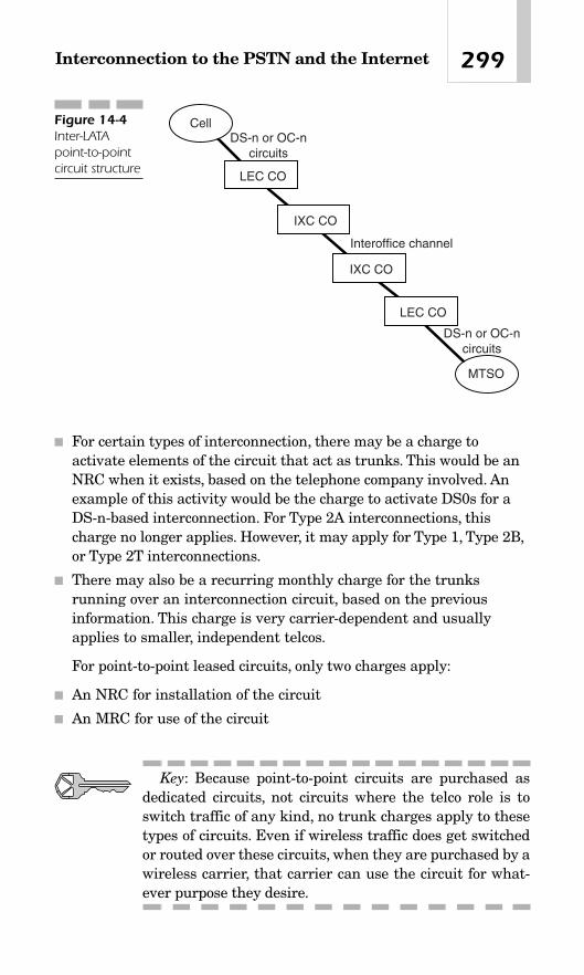
■ For certain types of interconnection, there may be a charge toactivate elements of the circuit that act as trunks. This would be anNRC when it exists, based on the telephone company involved. Anexample of this activity would be the charge to activate DS0s for aDS-n-based interconnection. For Type 2A interconnections, thischarge no longer applies. However, it may apply for Type 1, Type 2B,or Type 2T interconnections.
■ There may also be a recurring monthly charge for the trunksrunning over an interconnection circuit, based on the previousinformation. This charge is very carrier-dependent and usuallyapplies to smaller, independent telcos.
For point-to-point leased circuits, only two charges apply:
■ An NRC for installation of the circuit
■ An MRC for use of the circuit
Key: Because point-to-point circuits are purchased asdedicated circuits, not circuits where the telco role is toswitch traffic of any kind, no trunk charges apply to thesetypes of circuits. Even if wireless traffic does get switchedor routed over these circuits, when they are purchased by awireless carrier, that carrier can use the circuit for what-ever purpose they desire.
299Interconnection to the PSTN and the Internet
Cell
IXC CO
IXC CO
LEC CO
LEC CO
MTSO
Interoffice channel
DS-n or OC-ncircuits
DS-n or OC-ncircuits
Figure 14-4Inter-LATApoint-to-pointcircuit structure

14.7 Cost-per-Minute ChargesPrior to the passage of the Telecom Act of 1996, rates for all types ofinterconnections ranged anywhere from $0.02 per minute (i.e., Type 2Binterconnections) to more than $0.05 per minute (i.e., Type 2A inter-connections).
Since passage of the Telecom Act of 1996, rates for all types of inter-connections have dropped to a range of less than $0.01 per minute to$0.03 per minute. Independent telephone companies usually chargehigher rates per minute, because they have to compensate for the factthat they have much less volume to work with than, say, the compa-nies that grew out of the former Bell company (Verizon, SBC, Quest,Bellsouth).
For dedicated interconnections to IXCs, wireless carriers can obtainrates from around $0.01 to $0.04 per minute. The core issue, which drivesthe exact rate per minute charged to wireless carriers for this type ofinterconnection, is total billable minutes per year.At the same time, wire-less carriers may be required to sign long-term contracts of up to 3 yearsin order to obtain lower rates. Volume (minutes of use) and term (years)commitments are what drive lower rates for interconnection contracts.
14.7.1 Rating Structures
There are two structures used to determine the cost-per-minute rate thattelcos charge to wireless carriers for interconnection: banded rate struc-tures or flat-rated structures. Either method can apply to tariffs or cus-tom contracts (see Sections 14.9.1 and 14.9.2).
14.7.1.1 Banded Rates Banded tariff structures are still used bymany landline carriers to assess charges to end users, whether they areresidential consumer customers or business customers. Here is how thisstructure works.
A landline telco designates anywhere from three to eight concentriccircular geographic bands whose center is a particular central office. Inthis context, the central office is called the rate center. The rate center isthe central office where the interconnect exists and is used for rating andmeasuring mobile-to-landline wireless calls.
Each band encompasses a specific mileage range outward from therate center. Calls that terminate to landline destinations within mileagebands that are closer to the rate center are cheaper. Conversely, calls to
Chapter 14300

destinations within the farthest mileage band away from the rate centerare rated as the most expensive. As the mileage bands progress outwardfrom the rate center, the cost to carry traffic to destinations withinmileage bands also increases correspondingly on a sliding scale. Forexample, if a telco uses three mileage bands, the first band could encom-pass 0 to 8 miles from the rate center. This is known as Band 1. The sec-ond band could represent a circular band that is 8 to 25 miles away fromthe rate center; it would be known as Band 2. The third mileage bandrepresents a concentric circular band that is 25 or more miles from therate center. Calls to someone living in Band 1 are rated the cheapest;calls to persons in Band 3 are rated the most expensive. Banded ratestructures are more difficult to administer and deal with for all partiesinvolved (see Figure 14-5).
14.7.1.2 Flat Rates The more progressive telcos, including long-distance carriers, have implemented what are known as flat-rate pric-ing structures. Because of intense competition in today’s marketplace,more and more landline carriers are using flat-rate pricing. It is easierto administer for telcos, and it is easier for everyone to understand.
Flat-rate pricing reflects a very simple pricing mechanism: Telcoscharge carriers one flat rate (e.g., $0.02 per minute) to terminate callsacross an entire region, usually a LATA. All mobile-to-landline wirelesscalls are rated exactly the same from the rate center to any destination(LATA-wide in the case of a wireless interconnection). It does not matterhow far away from the interconnection point, or the rate center, a mobilecall terminates to the landline.
This rating structure has several advantages. First, it is much easierto administer and deal with for both the telco and the wireless carrier.
301Interconnection to the PSTN and the Internet
Band 1 - 0-1 miles
Band 2 - 1-25 miles
Band 3 - 25+ miles
C.O.
1 cent/minute
2 cents/minute
3 cents/minute
BANDED RATE STRUCTURE
MSCor
BTS
Ratecenter
Figure 14-5Banded ratestructure

Another advantage that flat-rate tariffs provide is that, because theyoffer LATA-wide service, theoretically a wireless carrier does not have toinstall more than one interconnection in any given LATA. This wouldsubstantially decrease the monthly recurring costs for circuits and asso-ciated trunks over interconnections by reducing the net amount of inter-connections required.
14.8 Special ConstructionCharges
When a wireless carrier orders any type of interconnection, special construction charges may apply. This usually occurs when the wirelesscarrier requires an interconnection or point-to-point circuit to be implemented in a very remote rural or mountainous area. If the wire-less carrier places an order for service, and the telco’s cable facilities area long distance away from the wireless carrier’s location, where no cablefacilities are available, then the telco will have to make what is knownas a reusability assessment. This assessment revolves around whetheror not other entities (residences or businesses) will be able to make useof a newly required cable facility the telco will have to install to supportthe wireless carrier’s order within a given period of time (e.g., 5 years).If no other entities will be able to make use of the cable, the cost totrench the cable must be borne by the wireless carrier, and they are thencharged accordingly if they still wish to pursue the service order and paythe fee. This fee is known as a special construction charge. Complex for-mulas are used to assess whether or not the telco can pass on these coststo the wireless carrier. They are known as the reusability factor.
Depending on the amount of special construction that is required, thecost could be several thousand dollars, or even in the tens of thousandsof dollars. If special construction charges are prohibitively high, the wire-less carrier could seek other options for connectivity. These optionscould include seeking out other sites for interconnection or more cre-ative options such as working with the telco to implement a microwaveradio link between the two networks. This would involve the wirelesscarrier purchasing a low-capacity microwave radio system, placing onenode or antenna at its site, and placing another node or antenna at thetelco’s nearest CO. The microwave antenna could be placed on the roofof the CO.
Chapter 14302

14.9 InterconnectionAgreements
Two methods are used by landline carriers to develop interconnectionagreements with wireless carriers: tariffs and custom contracts. This ishow the two parties formalize an interconnection purchase. Sometimesa combination of the two is used when custom contracts are developedbased on reduced tariff rates (see Section 14.9.2). Both tariffs and cus-tom contracts contain common sections designed to protect both par-ties involved in the interconnection purchase: the telco and thewireless carrier.
One of these sections is the terms definition section where acronymsand other terms used in the documents are defined clearly. This is a legalway of protecting both parties from the potential to misconstrue meaninganywhere within the tariff or contract. Another section defines the rolesand responsibilities of both parties.This is mainly designed to protect thetelco, so if an interconnection is turned up after the due date given to thewireless carrier, the telco is covered if the tardy turnup is due to the wire-less carrier not meeting its responsibilities that are stated in the tariff.These requirements could include not supplying power for circuit termi-nation equipment, not supplying space for the circuit termination equip-ment, or even not supplying cable from its own telco/data room to thepremises demarcation point, or demark. The demarc marks the physicalseparation of responsibilities between the telco and its customers, whichin this case is a wireless carrier.
14.9.1 Tariffs
The cost-per-minute rates that the landline carriers charge to terminate(connect) calls to the PSTN are usually stated in the form of tariffs,which must be filed with and approved by the respective state PUCs.Tariffs state the rates charged for services, as well as the responsibilitiesof both the telephone company and the party that is purchasing service.In this case, that party is a wireless carrier. Although it may seem oddthat the party purchasing service has responsibilities, tariffs aredesigned in this manner to minimize the legal risk to telephone compa-nies in case there are service problems.
When a wireless carrier purchases an interconnection from a landlinecarrier, the tariff rates apply for all charges. Tariffs state the cost-per-
303Interconnection to the PSTN and the Internet

minute rates for carrying mobile-to-land calls and rates charged for leas-ing the circuits.
Key: No option exists to negotiate tariffs when orderinginterconnections from a landline telco. Tariffs are used as aregulating measure by the states to ensure that the big boyon the block does not throw his weight around, so to speak.Rate stability for the largest telcos ensures that the smallertelcos and CLECs can compete on a more level playingfield. Nonetheless, the landline telcos also have the optionof negotiating custom contracts with their wireless inter-connection customers via rules and special tariff optionsinstituted by the state PUCs. Custom contract rates areusually derived from tariff rates.
Every few years, the incumbent telcos will gather their interconnec-tion customers together to discuss rate restructuring (e.g., ratedecreases). Once a proposal for tariff restructuring is presented to theincumbent telco, they review it internally. Once approved internally, thetelco then submits the new tariff to the state PUC for approval. Thisprocess can take anywhere from 6 months to a year to complete. Tariffsare public documents.
Prior to passage of the Telecom Act of 1996 , one of the largest stum-bling blocks that existed for wireless carriers in obtaining equitableand fair interconnection rates and terms was the fact that LECs didnot grant wireless carriers the cocarrier status in accordance with FCCorders. Cocarrier status dictates that when LECs determine intercon-nection rates and terms they should treat wireless carriers just as theywould treat another LEC or IXC in terms of how those carriers inter-connect to the LEC’s network and what rates they are charged perminute to transport calls into the LEC’s network. This could apply toany number of relationships: incumbent telco to LEC interconnection,CLEC to LEC interconnection, independent LEC to independent LECinterconnection, or IXC to LEC interconnection. Technically, it is illegalfor any LEC to charge a wireless carrier a higher rate to terminatecalls than it charges other carriers to terminate similar calls into theLEC’s network.
Chapter 14304

14.9.2 Custom Contracts
If interconnection rates charged to wireless carriers are not derived froma tariff, they are formalized through a written interconnection agree-ment known as a custom contract. Custom contracts are very similar totariff agreements, but the rates contained in a custom contract are lowerthan tariffed rates. Custom contracts are used by all the telcos but some-times under different rules. As usual, the rules that apply to an incum-bent telco (usually a former Bell company) are more stringent than therules that apply to other telcos such as CLECs and other smaller inde-pendents. Contracts are private documents.
14.10 Least-Cost RoutingWireless carriers must ensure that all mobile-originated calls are routedto their destinations as inexpensively as possible. This process is knownas least-cost routing.
Key: The wireless carrier’s own network should alwaysbe used whenever possible as the first route to terminatemobile-originated traffic to the landline network or to othermobile subscribers within wireless carrier clusters.Remember, a cluster is a geographically contiguous groupof wireless markets all owned by the same carrier. Ideally,mobile-originated wireless traffic should always be directedover the wireless carrier’s own network to the PSTN inter-connect that is closest to the destination of the wireless call.So, the bottom line is that least-cost routing can involve theuse of an array of telco interconnects, along with the wire-less carrier’s own backhaul network.
For calls within a wireless carrier’s own system, in a market clusterwhere the carrier has deployed its own signal transfer points (STPs),inter-MSC SS7/IS-41 links can and should be used for least-cost routing
305Interconnection to the PSTN and the Internet

purposes. These links are known as IMTs, using SS7 ISDN User Part(ISUP) for call management.
Standard least-cost routing methodology usually employs three pos-sible routes, cheapest to most expensive, for directing mobile-originatedtraffic from point A (the wireless network) to point Z (any landline des-tination or another wireless carrier’s network). If the operational statusof the first trunk group (the cheapest option) is all-trunks-busy, callswill automatically be directed to the second trunk group (the secondcheapest option), and then to a third trunk group if necessary (the mostexpensive option) if the second group is also all-trunks-busy. This type ofrouting is accomplished by having what is known as a route pattern des-ignated for every NPA-NXX combination in the United States, andevery international country code in the world. The route pattern pointsto the three possible trunk groups that are available to route traffic. Theroute patterns exist in the switch—the MSC. All switches, whetherPBXs, access tandems or toll tandems, have route patterns for all NPA-NXX combinations.
Key: Obviously, the goal with least-cost routing is toensure that the first trunk group is always properly engi-neered to handle most, if not all, calls, thereby avoidingoverflow to the most expensive routes. Usually, where thereis overflow from the first trunk group to the subsequenttrunk groups, it is due to a spike in network traffic that istied to some type of public disaster or emergency.
14.11 Internet ConnectionsWireless carrier interconnections to the Internet would take place ideallydirectly from the MSC to the ISP’s POP. This is the ideal connection sce-nario because the wireless carrier requires adjunct server and routerequipment in place to manage Internet traffic to and from its customers.
This connectivity could take many forms, simply because there aremany options available today from incumbent LECs (ILECs) and CLECs.The exact amount of bandwidth required would be a reflection of wirelesscarrier traffic studies that spelled out how much bandwidth is needed.This projection should always take projected growth into account. Theoptions wireless carriers have for connecting their networks to the Inter-net are as follows:
Chapter 14306

■ The wireless carrier could implement a gigabit Ethernet connectiondirectly to the ISP, as many ISPs today would accept this type ofconnection and plenty of carriers are out there who supply metroEthernet connections. A great example is SBC’s GigaMAN® service.
■ Wireless carriers could connect to the Internet using OC-n circuits.
■ Unchannelized DS3 circuits could be used.
■ DS1 or multiple DS1 circuits could be used to support lesspopulated, rural markets.
Key: As the number of Internet-based applications andservices provided by wireless carriers continues to surge,this connectivity will become critical to wireless carrierinfrastructures. That said, it is always wise to implementdual-homed Internet connections over separate and diversephysical routes to two distinct and physically separate ISPPOPs. This also means that there should be diverse accessfacilities into the MSC site itself. This should have alreadybeen the case, to support sound backhaul network andPSTN interconnections. This type of design should beimplemented even if it means obtaining Internet accessservice from two separate ISPs. See Figure 14-6.
14.12 Wireless Local NumberPortability (WLNP)
Local number portability (LNP) describes the ability of customers toswitch service from one carrier to another. In the wireless world, wirelessLNP (WLNP) means changing wireless carriers but keeping your wire-less phone number. It can also mean porting, or changing, your landlinehome phone number to become your mobile phone number. WLNP wentinto effect on November 24, 2003. It was an FCC mandate that requiredall carriers in the industry to prepare for interconnecting into a nationaldatabase that managed the porting of numbers between wireless carri-ers. Naturally, portability applies to residential customers, business cus-tomers, and wireless carriers as well (for numbers they obtained throughinterconnection to the PSTN).
307Interconnection to the PSTN and the Internet

Key: The portability rules that went into effect inNovember 2003 included service portability, in other words,the ability to port telephone numbers from landline telcosto wireless, as well as from one wireless carrier to anotherwireless carrier.
For years, mobile subscribers complained about the inability to retaintheir mobile phone number, and how that has virtually held themhostage to their current wireless service provider. The FCC, along withconsumer advocates, believed that WLNP would enhance competitionand allow subscribers to choose the carrier they want.
After opposing the measure, carriers won a one-year delay of whatthey called an unfunded government mandate because they neededtime to train personnel and coordinate WLNP with public safety agen-cies. The CTIA said it would cost $1 billion to initiate number portabil-ity and another $500 million each year to support the new service. TheCTIA claims the cost will drain resources away from needed networkupgrades, filling gaps in coverage, and delivering customer advancedservices such as 3G. Churn, or service cancellation, was also a concernof wireless carriers. The concern of wireless carriers was echoed by areport released In-Stat/MDR. Analysts said that where portability wasimplemented overseas, the rate of customer churn increased by as muchas 50 percent. The research firm estimated that over 22 million wirelesssubscribers would change carriers during the first full year that WLNPwas in effect. That rate would “fall to 30 percent by 2004, finally level-
Chapter 14308
Internet
Mobile Switching Center
Diverse Route via Diverse
Entrance Facilities
Diverse Route via Diverse
Entrance Facilities
ISP POP#1
ISP POP#2
Figure 14-6Wireless carrierconnectivity tothe Internetshould beaccomplishedusing dual-homed, diversecircuits todifferent ISPPOPs.

ing off at 10 percent annual churn.” In reality, after one full year of beingin place, only 8.5 million subscribers changed wireless carriers whilekeeping their wireless phone numbers. In any case, WLNP is a goodthing for consumers, which means that long term, it will be good for theindustry itself.
14.13 ReciprocalCompensation
Mutual compensation described a concept that existed in the early1990s, where wireless carriers were trying in vain to obtain agreementwith the landline telcos to have the telcos compensate the wireless car-riers for calls that originated on a landline phone and terminated to thewireless network. The thinking was that it was only fair for compensa-tion to be a two-way street, because wireless carriers also spent billionsto develop their networks. They just did it in a shorter period of time.
This issue heated up in the early to mid-1990s because the prolifera-tion of wireless service resulted in a large increase in landline-to-mobilephone traffic. The wireless carriers came to the point where they felt itwas only fair that they also be compensated for calls that terminate ontotheir networks. When a wireless carrier transports a mobile-to-land tele-phone call, this call originates within the wireless network and termi-nates to the PSTN (the landline network). Wireless carriers are requiredto pay a specified cost per minute for each of these calls to the landlinetelco. However, when landline customers called a mobile telephone num-ber (land-to-mobile calls), the landline telephone company did not paythe wireless carrier any monies for terminating any of these calls ontothe wireless network. The LECs got away with not paying mutual com-pensation to wireless carriers for years. Part of the reason for this wasbecause the LECs—the former Bell companies—had more political heft,which they used to keep the cellular carriers off balance and always at adisadvantage.
On December 15, 1995, the FCC issued a Notice of Proposed Rule-making dictating that a concept known as reciprocal compensationshould govern interconnections between commercial mobile radio service(CMRS) providers (cellular, PCS, paging, enhanced specialized mobileradio carriers, or EMSR) and LECs. Reciprocal compensation simplytakes mutual compensation one step further by formalizing it, sayingthat under many (if not all) circumstances, landline and wireless carriers
309Interconnection to the PSTN and the Internet

should bill each other for calls terminating to each other’s networks. Rec-iprocal compensation is the ultimate maturing and resolution of themutual compensation and cocarrier status issues.
The Telecom Act of 1996 formalized the reciprocal compensation issueby making it law. It stated that if a wireless carrier is being charged acertain cost-per-minute rate for calls terminating to the landline net-work, then the landline carriers have to pay the wireless carrier for callsthat terminate to the wireless network as well. Reciprocal compensationwas the government’s way of ensuring that the financial playing fieldbetween landline and wireless carriers was finally leveled off; fairness isnow ensured by the force of law.
14.14 Enhanced 911 Service(E-911) and LocatorTechnology
911 service becomes Enhanced 911 service when automatic numberidentification (ANI) and automatic location information (ALI) from awireless phone is provided to the 911 operator—the Public SafetyAnswering Point (PSAP). In other words, the name and location of thecaller is provided.
In the United States in the year 2003, 198,729 911 calls were madedaily. Because there are now 175 million wireless subscribers in theUnited States, it is likely that many 911 calls will be originated by mobilesubscribers.
The U.S. regulation known as the FCC E-911 mandate was passed in1996, requiring all wireless service operators to provide an emergency911 caller’s cell phone location to the PSAP to within 100 meters 67 per-cent of the time. The initial deadline for the commencement of imple-mentation was October 1, 2001, and no major wireless carrier met thedeadline. The FCC granted temporary waivers and extension of time.However, noncompliant phone companies have received server fines(AT&T was fined $2.2 million in May 2002) and the FCC is now increas-ing the pressure for compliance. The primary difference between PhaseI and Phase II is the degree of caller location accuracy. Phase I requiresaccuracy to the cell/sector level, and Phase II requires accuracy within125 meters 67 percent of the time.
Sprint, Verizon Wireless, Cingular, T-Mobile, and AT&T Wireless (nowpart of Cingular) all filed requests for waivers to the October 1 deadline.
Chapter 14310

The biggest hurdles have been rolling out the required network softwareand infrastructure and coordinating with emergency response agencies.
The Phase 2 requirements of wireless E-911 were to be implementedby October 31, 2001. Phase 2 for network-based implementationsincludes the ability to identify the latitude and longitude of a mobilephone within a radius of less than 125 meters 67 percent of the time andwithin 300 meters 95 percent of the time. The handset-based implemen-tation requires 100 percent compliance of new or updated mobile phonesby the end of 2004. Full Phase II compliance is now required by Decem-ber 31, 2005. As usual, the Phase II deadline had been December 31,2004, but wireless carriers requested a postponement from the FCC(until December 31, 2005) and they received it.
The fundamental operational needs to support Phase I and II 911include the following:
■ A mapping and geolocation database for PSAP call routing
■ Geographical-boundary provisioning
■ Out-of-band signaling for real-time location updates
■ A large processing capacity for location calculation
■ Interactive call control
■ High reliability and manageability
The intensive processing demands, as well as the need for large data-base support and management, are best served by an adjunct computer-based solution. Additionally, location technology offers myriad verticalservice opportunities beyond wireless 911, which could help shoulder theanticipated Phase II cost burden.
The FCC proposed the implementation of regional (state and local)cost mechanisms to cover the cost of implementing wireless E-911. TheFCC also stipulates that wireless service providers have the same legalliabilities as the landline providers to successfully deliver E-911 servicesto their customers.
14.14.1 Locator Technologies
There are two approaches wireless carriers can select to determine thelocation of a mobile subscriber for E-911 purposes: network-based solu-tions or handset-based solutions.
Network-based solutions employ triangulation and timing, using pre-cise measurements of the wavelength differentials between base stationsto reveal the location of a mobile user. In other words, network-based
311Interconnection to the PSTN and the Internet

solutions rely on triangulation technology. This approach has been deter-mined to cost a lot more than a handset-based solution (e.g., GPSreceivers in mobile phones). One network-based solution uses time dif-ference of arrival (TDOA) technology. With this approach, at least threebase stations must be detected by the mobile handset over the controlchannel to resolve ambiguities in location. They must also be tightly syn-chronized. The base stations calculate the time it takes for the signals totravel from the stations to the handset, and back to the stations. Thisyields the distance of the handset from the base stations. The wirelesssystems will then map the three calculated distances, and whereverthese locations meet reveals the position of the handset.
Another network-based technology option is the direction of arrival(DOA) technique. DOA requires only two base stations, and the base sta-tions must have an array of antennas. These base stations also calculatethe distance of the handset from the base stations like TDOA. In addi-tion, DOA also measures the angle of the signals being sent back to thebase stations. The distances and angles measured together can then beused to calculate the location of the handset.
These network-based technologies are the most promising triangula-tion techniques and the easiest to implement. No change in standards isrequired, and, best of all, they work with unmodified phones. However,one drawback is that the mobile position significantly degrades in theurban environment due to signal reflection, and accuracy decreaseswhen the mobile phone is close to base stations(s) and/or in hilly areas.Service providers are discovering that implementing these new servicescan be costly and time-consuming. Some estimates say the average costto implement a network-based solution—per base station—is $500,000.
Handset-based solutions use GPS and a GPS receiver in the handsetto communicate user locations to the PSAP and the wireless serviceprovider.
Key: GPS technology can pinpoint handsets within 15feet outdoors and 100 feet inside buildings, which exceedsthe FCC’s requirements. GPS units are placed throughouta wireless network. As these units keep track of GPS satel-lites orbiting the earth, they pass along key satellite infor-mation, including estimated time of the signal’s arrival tonearby wireless handsets, which are equipped with scaled-down GPS receivers. Then, based on time differencesbetween when the network’s GPS units and handset’sreceive signals from the satellites, it is possible to preciselypinpoint the caller’s location.
Chapter 14312

One downside to this option is that because GPS receiver units mustbe included in the mobile handsets, the handsets will then consume a lotof power. But the upside is that the handset-based solution is more accu-rate and provides universal coverage. To attain widespread use of thisoption, new GPS-enabled handsets would have to be purchased by manywireless customers over a relatively short period of time. Considering thepersistent level of promotions offered by wireless carriers to provideincentives for their customers to upgrade their wireless handsets, thisobjective does not appear difficult to achieve.
The two technology approaches to locator technology are based onmicromeasurement of transmission time for wireless signals to travelthrough space and require the widespread deployment of specializedhardware units and network overlays.
The downside to locator technology is that it effectively turns themobile into a de facto tracking device. Users can be located anytime, any-where—especially with the GPS handset-based solution.
Locator technology, although Big Brother—like in nature, can beapplied in many application scenarios as listed here:
■ E-911 emergency location
■ Personal child security
■ Asset tracking and people finder
■ Fleet management
■ Telematics
■ Driving directions (includes integration with software such asMapQuest)
■ Wireless gaming
■ Location-based billing
■ Information directory service
■ Push/pull advertising
■ Electronic house arrest
■ Enterprise applications
■ Field force effectiveness
■ Mobile worker management
It would be an understatement to say that the industry is lukewarmabout wireless location-based services. The main reason: Carriersinvested billions of dollars into getting their networks E-911 compliantand are now trying to recover those costs from a location-based services(LBS) market that many analyst firms project will not be generating
313Interconnection to the PSTN and the Internet

more than tens of millions in the next few years. In spite of this, carriersare deploying location-based applications with regular frequency, andalthough pure-play LBS applications, like car navigation systems andtelematics, may not be the hottest sectors, consumer and business appli-cations with location-based elements are becoming (or will become) cru-cial to most carriers’ service offers.
Many wireless carriers now offer location services for a fixed monthlyfee, where tracking can be monitored via an Internet site accessed bycustomers. This is how many parents today are keeping track of theirteenage kids. Locator technology is also being used to track waywardspouses and employees who tend to slack off. Intrusive? Yes. Effective?Yes. Scary? Yes.
The essential difficulty for the wireless carriers to deploying locatortechnology in their networks is that the current time measurement loca-tion technologies (based on triangulation) have marginal accuracy andrequire an investment of billions of dollars. The wireless industry doesnot have this capital to invest. Another concern is that this financial hur-dle has the potential to set back the urgently needed enhancement topublic safety and stall much needed revenue generation from premiumlocation-based services. This is becoming a major concern due to the factthat the U.S. subscriber base is now over 175 million subscribers (as oflate 2004).
The following information presents just a snippet of what some enter-prising companies are developing to support the locator marketplace.
A company known as Landmat has developed a variety of location-based products. PalTrak does what its name implies: It locates friendsconnected to the wireless network and arranges meetings, identifiesmeeting places, and even keeps track of the children. DateTrak is asimilar service with advanced messaging and more controlled trackingfeatures built in. And its cobranded Time Out Mobile service links TimeOut’s reams of listing and entertainment content to Landmat’s naviga-tion system.
A firm called Xora has built the ultimate Big Brother technology forwireless devices, allowing companies to track their employees’ timesheets, jobs, and physical locations using GPS-enabled phones.
MapQuest, one of the most recognizable brands on the Internet, hasbrought its mapping functionality to the wireless network, adding loca-tion-based features and even voice-recognition technology.
Chapter 14314

Test Questions
True or False?
1.______ Telephone numbers are not purchased for sale to cellularcustomers when a Type 2B interconnection is installed.
2.______ Type 2A interconnections are direct links to telco end offices.
3.______ Wireless carriers are required to purchase an entire NXXcode when obtaining a Type 1 interconnection.
Multiple Choice
1.Type 1 interconnections to the PSTN:
a. Terminate directly to a telco access tandem
b. Terminate directly to a telco end office
c. Carry local/EAS traffic
d. Carry 911, 411, and operator-directed traffic
e. a and c only
f. b, c, and d only
2.The Telcordia Technical Reference for Interconnection to the PSTN is:
a. TR-000-240
b. TR-140-000
c. Reciprocal termination
d. GR-000-145
3.Which type of interconnection displays the ultimate case of least-costrouting?
a. Type 1
b. Type 2B
c. Type 2A
d. Type 2T
315Interconnection to the PSTN and the Internet

4.What is the difference between a banded interconnection structureand a flat-rated interconnection structure?
a. A banded rate structure charges one rate for calls terminating anywhere in a LATA; flat rate does not.
b. A flat-rate interconnection structure charges higher ratesdepending on how far away from the originating end office (oraccess tandem) the call terminates (connects). A banded-ratestructure charges different rates for different states.
c. There is no real difference between banded interconnectionstructures and flat-rate interconnection structures.
d. Banded interconnection structures charge higher rates,depending on how far away from the originating end office (oraccess tandem) the call terminates (connects). Flat-ratedinterconnection structures charge one rate, LATA-wide.
5.The reason that wireless customers are charged for land-to-mobilecalls, even though they did not originate the call themselves, isbecause:
a. Wireless carriers are greedy and have all engaged in price-fixing practices.
b. Land-to-mobile calls are still using extensive resources of thecellular carrier’s infrastructure.
c. Wireless carriers are always charged for land-to-mobile calls also.d. All of the above.e. None of the above.
6.Dedicated interconnections to IXCs are justified by doing a costanalysis to verify:
a. That there is always going to be one million minutes per monthdirected over the interconnection to the IXC.
b. That a Type 2A interconnection is not necessary.c. That the monthly cost for the DS1 circuit that allows for
dedicated access to the IXC is equal to or less than the totalcost of all mobile-originated calls that are routed to the IXC asswitched access through a Type 1 interconnection to the LEC.
d. All of the above.
7.Wireless interconnections to the PSTN are also known as:
a. Localitiesb. CLECsc. POPsd. IXCs
Chapter 14316

Roamingand
IntercarrierNetworking
CHAPTER 1515
Copyright © 2005 by The McGraw-Hill Companies, Inc. Click here for terms of use.

15.1 OverviewRoaming defines the use of wireless service outside a wireless sub-scriber’s home service area. In other words, wireless customers are in aroaming state when they use their mobile phone outside of the generalarea where they originally purchased their wireless service. Each wire-less carrier determines its own home service area on the basis of the spe-cific market where they are operating. In each market, one carrier maytry to maintain a larger home area footprint (coverage area) in order togain a competitive edge over its in-market competitor. The home servicearea may be designated on a large wall map in sales offices where serviceis initially obtained by wireless subscribers.
Key: Note that due to the size of the 1900 MHz personalcommunication service (PCS) metropolitan trading area(MTA) markets, carriers operating in that frequency bandwill by definition have larger home areas because thesemarkets are huge compared to the traditional 850 MHz cel-lular markets.
Once the mobile phone is powered on in a roaming market, customersbecome aware they are in a roaming state through the autonomousmobile registration process. When the mobile phone is powered on in aroaming service area, the phone registers with the system where it iscurrently located. Key elements of autonomous mobile registrationprocess are the transmission of the mobile’s mobile identification number(MIN), otherwise known as the 10-digit telephone number; the electronicserial number (ESN) of the phone, which is essentially the phone’s fin-gerprint; and the System Identification (SID). The SID is a three- or four-digit number that uniquely identifies a mobile user as belonging to aspecific home market. A roaming indicator will then appear on the liq-uid-crystal display (LCD) screen of the mobile phone, in the form of theletter R or the word “roam.”
Wireless carriers’ definition of home service areas is continuallyexpanding due to aggressive cluster expansions by all major wirelesscarriers, even to the point of nationwide footprints, which are mostcommon today. This is contributing to the commoditization of roamingas an operational and revenue concept, which is leading to its position asa differentiator in marketing efforts. In other words, many wireless car-
Chapter 15318

riers today offer calling packages where roaming is free. This, in turn, isleading to the slow death of roaming charges (see Chapter 18).
Special rates apply to wireless customers who make calls while roam-ing in those cases where carriers do charge for roaming. These rates arevery carrier-specific and may fluctuate greatly between carriers acrossthe United States.The rates are very high compared to regular call rates,but roaming rates are continuing to decrease as more advanced inter-carrier networking systems have been implemented nationwide. Thesesystems based on Signaling Systems 7 (SS7) ultimately reduce costs andincrease efficiency.
Key: All wireless carriers impose higher fees than nor-mal for customers who place calls while roaming. This isespecially true for wireless carriers who have a large mar-ket presence in rural areas and who may rely heavily onroaming revenues by virtue of the fact that there are inter-state highways prevalent in rural areas, even if the poten-tial subscriber base is small. When mobile subscribers aretraveling for business or vacation by driving, they have nochoice but to register with and use roaming systems. Insome cases roaming fees are a large part of these carrier’soverall revenue streams.
15.2 The Early Days ofRoaming
In the first 10 years of the wireless industry, the validation of roamingcustomers occurred by having all cellular carriers directly network theirmobile switching centers (MSCs) together with private line circuits.These circuits validated customers for both antifraud purposes as well asbilling purposes. This setup existed because at that time there were notany large, nationwide ANSI-41/SS7 networks in place supporting wire-less carriers, which allow for carriers to more efficiently validate and billtheir customers.
Today, when wireless carriers do charge for roaming, they simplycharge a higher per-minute rate for calls made by customers who areroaming. But in the old days in the wireless industry (from 1983 to themid-1990s), a typical rate structure for a roaming call could be as follows:
319Roaming and Intercarrier Networking

1.A daily fee was assessed, whether a person who was roaming madeone call or 20 calls per day. This fee could be as high as $3 per day.
2.A cost-per-minute fee of anywhere from $0.50 to $1.50 was applied.
3.A per-call fee might have been assessed. This fee could be $0.50 to$1.00.
These higher rates were deemed necessary to cover the higher cost ofintercarrier networking in that time period, which usually involved ded-icated circuits either directly between carrier’s MSCs, or to roamingclearinghouses, or to both. Roaming clearinghouses are third-party busi-ness entities that accept roaming data from wireless carriers via dedi-cated circuits to the clearinghouse database location. The clearinghousethen manages and allocates the roamer billing monies amongst all wire-less carriers who subscribe to its service. Today the roaming clearing-houses are still used, but more for billing and monies exchange insteadof precall validation because of the now-widespread base of SS7 systemsin the wireless world.
From 1983 to the mid-1990s, in most cases someone who wanted tocall a person who was roaming would have to follow a cumbersome mul-tistep process in order to reach the person. This process was so customer-unfriendly that it inhibited roaming activity. The process was actually adeterrent to increasing roaming revenues because it was so clumsy:
1.A caller who wanted to reach a roaming customer would have toknow the exact destinations of the person who would be roaming.When wireless customers in those days signed up for service, theywere given a small catalogue that looked like a miniature telephonebook, which had a nationwide listing of roamer access numbers forall cellular carriers (A band/B band).
2.The caller would then have to dial the special roamer accesstelephone number from the catalogue described in the precedingpassage. This call would terminate into the switch (MSC) of themarket where the wireless customer was roaming to a roamer access port.
3.Then the caller had to dial the roamer’s 10-digit MIN once he or sheaccessed the roamer MSC.
This roaming structure is essentially extinct today for the most part,because of the deployment of more advanced intercarrier networkingsystems. These systems enable callers to transparently reach roamingcustomers anywhere, by simply dialing their 10-digit mobile phone
Chapter 15320

number. These advanced systems are enabled via the networking stan-dards known as ANSI/TIA-41 (American National Standards Insti-tute/Telecommunications Industry Association) and SS7-signalingsystems.
15.2.1 Roaming Agreements
All wireless carriers develop roaming agreements with each other, if theywant to ensure their customers can roam anywhere in the United States(or world) and be able to place a wireless call. Ideally, they should also beable to use the features they are accustomed to in their home markets.
Roaming agreements are business agreements developed betweenwireless carriers to outline the terms under which mobile customers ofeach carrier can roam into each other’s territories and still be able toplace and receive wireless calls. The most important part of the roamingagreement is to iron out rates that are acceptable to both parties, interms of what wireless customers will pay to place calls while roaming.Also, in order to operationalize a roaming agreement, the carriers mustexchange all their active line ranges with each other so that roamers canbe recognized when visiting nonhome wireless systems. Line ranges aredefined by the bucket of NPA-NXXs that carriers sell to their wirelesscustomers when they obtain wireless service (NPA � area code; NXX �exchange code). Along with the rates charged to roamers and line ranges,carriers also must exchange SID information—the system ID thatuniquely identifies each carrier in the markets where they operate.Wire-less carriers maintain entire departments of personnel dedicated tonothing but managing roaming and all its intricacies.
15.3 Modern RoamingSystems
15.3.1 Roaming and Digital Interoperability
A major roaming interoperability challenge exists with so many digitalwireless technologies being fielded by 850 MHz cellular and 1,900 MHzPCS carriers. As of 2005, there are five types of digital wireless tech-nologies in the U.S. marketplace:
321Roaming and Intercarrier Networking

■ IS-136, fielded by AT&T Wireless until its network is fullyconverted to GSM and integrated into by Cingular Wireless. Thereare likely other smaller, regional wireless carriers who may be usingIS-136 as well.
■ GSM, fielded by Cingular Wireless, Western Wireless, and T-Mobile.
■ CDMAOne, fielded by Verizon Wireless and Sprint PCS.
■ CDMA 1XEVDO, a 3G technology fielded by Verizon Wireless andAT&T Wireless (now Cingular) in several cities as of late 2004.
■ IDen technology, a proprietary TDMA technology fielded by NextelCommunications.
Motorola and other wireless handset manufacturers have addressedthis situation with the development of a trimode, multiband handsetthat operates using most of the technologies listed in the preceding list.A quadmode handset is in the works. This technology will continue toexpand and evolve, and in some form, mobile subscribers should alwaysbe able to place a call wherever they travel, regardless of where theyobtained their service.
15.3.2 Signaling System 7 (SS7) Overview
Up until the early 1980s, the signaling for a telephone call used the samevoice circuit that the telephone call traveled on—this was known as in-band signaling.This method of signaling used the same physical path forboth the call-control signaling and the actual connected call. This ineffi-cient method has been replaced by out-of-band or “common-channel” sig-naling techniques such as SS7. SS7 is an internationally standardizedprotocol used by telecom carriers of all types for interoffice signaling, callestablishment, billing, routing, and information-exchange functions. Inthe public switched telephone network (PSTN) and today’s wireless net-works, SS7 is a system that puts the information required to set up andmanage telephone calls in a separate network rather than within thesame network used to make the call. SS7 signaling travels on a separate,dedicated overlay network. Using SS7, telephone calls can be set up moreefficiently and with greater security. Because control signals travel in aseparate network from the call itself, it is more difficult to violate thesecurity of the system. Special services such as call forwarding and wire-less roaming are easier to manage as well.
Chapter 15322

A network utilizing common-channel signaling such as SS7 is actuallytwo networks in one:
■ First there is the circuit-switched user network, which actuallycarries the user voice and data traffic. It provides a physical pathbetween the source and destination.
■ The second is the signaling network, which carries the call controltraffic—the SS7 network. It is a packet-switched network using acommon channel-switching protocol. SS7 has become the de factosignaling standard in the telecom world—both wireline andwireless.
SS7 has been in use in the wireline networks since the late 1970s andearly 1980s.Throughout the 1980s, competing wireless carriers had theirMSCs connected together directly in a meshed architecture to facilitateroaming activity with each other. As wireless network growth exploded,a hubbed signaling architecture became necessary to increase efficien-cies and cut costs. SS7 was the answer. Wireless carriers have beenimplementing SS7 on a large scale since the early 1990s to facilitatenationwide roaming for mobile customers.
There are multiple functions of the SS7 protocol in today’s networks,as follows:
■ Setting up and managing the connection for a call
■ Tearing down the connection when the call is complete
■ Billing
■ Managing signaling in support of vertical services such as callforwarding, calling party name and number display, three-waycalling, and other intelligent network services
■ Managing the routing for toll-free (800, 888, 866, 877) and toll (900)calls
■ Wireless and wireline call service, including mobile subscriberauthentication and roaming
An example of information that may be contained in SS7 messages:
1. “What’s the best way to route a call to a specific NPA-NXX (e.g.,708-431)?”
2. “The route to network point 587 is crowded. Use this route only forcalls of priority 2 or higher.”
323Roaming and Intercarrier Networking

3. “John Doe is a valid wireless subscriber. Continue with setting uphis wireless call.”
In today’s wireless networks, SS7 infrastructures are used to trans-port ANSI-41D messaging to other wireless carriers in support of keyfeatures that ANSI-41D allows for, namely (automatic) call delivery andintersystem handoff. The Mobile Application Part (MAP) of the SS7 stan-dard is what addresses the registration of roamers and the intersystemhand-off procedure in wireless mobile telephony.
Key: ANSI-41D messages containing subscriber profilesare encapsulated into SS7 messages and transportedacross SS7 backbone networks to authenticate roamersand support seamless roaming (see Sections 15.5 and 15.6).
The primary function of SS7 is to provide call control, remote networkmanagement, and maintenance capabilities for interoffice telecommuni-cations networks. SS7 performs these functions by exchanging controlmessages between reserved or dedicated channels known as signalinglinks and the network points that they interconnect. There are threekinds of network points, which are called signaling points: serviceswitching points (SSPs), signal transfer points (STPs), and service con-trol points (SCPs). SSPs are PSTN or wireless network switches used tooriginate or terminate calls. They are also used to communicate on theSS7 network with SCPs to determine how to route a call or set up andmanage some special feature. SCPs are databases used to support SS7networks and can contain routing data and information on calling cards.Traffic on the SS7 network is routed by STPs.
15.3.3 Signal Transfer Points (STPs)
STPs are data switches that relay SS7 messages between networkswitches and databases in an SS7 network. Their main function is toroute SS7 messages to the correct outgoing signaling link, based on SS7message address fields known as signaling point codes (SPC), or pointcodes for short.
Chapter 15324

Key: An SPC, or signaling point code, is a numericaddress that uniquely identifies each signaling point in theSS7 network. In this case, the STPs are network nodes, asare the MSCs. Point codes are used to direct messages tothe appropriate network destination. Each switch, STP,and Intelligent Peripheral (IP) has a unique point code inan SS7 network. All wireless carrier STPs are identified byunique point code addresses. Point codes are equivalent tothe IP addressing of the SS7 world, and their numberingconvention is xxx.xxx.xxx. Point codes consist of nine digits.The first three digits represent the network, the secondthree the cluster, and the third three identify the member(the node or device). Any device that processes SS7 trafficin any way must have a point code assigned to it.
STPs have a dual functionality: They act as both network hubs andSS7 packet switches. To facilitate SS7 functionality in the wirelessworld, wireless carrier MSCs are connected to STPs. Physically, STPscan be built-in adjuncts to the MSCs, or they can be stand-alone systemssuch as Tekelec’s Eagle family of STPs. This configuration depends onthe maker of the MSC as well as the engineering and operations prac-tices of the wireless carrier. Larger wireless providers procure their ownSTPs, and then connect their STPs to the MSCs, usually in a regionalarchitecture. These links that connect MSCs to the wireless carriers’mated STP pair are implemented using 56 Kbps or DS1 circuits, and areknown as A (access) links. This is how the STP acts as a hub: MultipleMSCs will connect to one mated STP pair. Smaller, regional wireless car-riers sometimes lease STP space from the larger carriers to avoid thecost of procuring their own STPs.
Just as the wireline telephone companies deploy their STPs in matedpairs in order to achieve equipment redundancy, wireless carriers alsodeploy their STPs in mated pairs. All telephone companies need theredundancy that is afforded by having a backup STP. The STPs must beconnected to each other for redundancy purposes, and these links can beimplemented by using either 56 Kbps data circuits, multiples of 56 Kbpscircuits, or full DS1 circuits. The link that connects a mated pair of STPsto each other is known as a C (cross) link.
325Roaming and Intercarrier Networking

Key: A mated STP pair will not be housed within thesame location (building). They will be geographically sepa-rated within a region, by at least 50 miles or so. Thisdeployment strategy is used to ensure availability and toensure that at least one STP is functioning in case ofregional disasters such as fire, flood, earthquake, and soforth.
15.3.4 The Home Location Register (HLR)
The HLR is the main database that houses identity information on valid“home” subscribers in a wireless network. A “valid” customer is one whopays his or her bills on time, and whose MIN/ESN has not been declaredillegitimate due to fraud (which is becoming a rare occurrence). The HLRis an integral component of wireless networks, necessary to acknowledgeand maintain subscriber information relating to the identity of valid cus-tomers in the switch’s home area, or home subscribers. When home sub-scribers power on their phones and register with the system over thecontrol channel, their registration is posted as a record in the HLR. TheHLR will maintain information on every active mobile in its system untilthey power off their mobile or move out of their home service area.
In the earlier days of the industry, from 1983 to the mid-1990s, mostwireless carriers (850 MHz cellular carriers) deployed HLRs as physicaladjuncts to their MSCs in every market. As SS7 technology wasdeployed, and as wireless markets expanded and became more sophisti-cated with the deployment of digital wireless technology and increasedcustomer expectations, wireless carriers considered modifying their net-works so only one HLR was used—a centralized HLR. Many large wire-less carriers today have deployed centralized HLRs. This represents oneHLR—one database—for all the carrier’s market holdings. If a wirelesscarrier owns multiple wireless markets, the MSCs from all these mar-kets would all be connected over the carrier’s own WAN backbone to thecentralized HLR. In these cases, the HLR will usually be at a geographiclocation that is central to all the carrier’s market holdings. The central-ized HLR could also be located at the carriers’ network operations center(NOC), or wherever the carrier’s billing system is housed.
Chapter 15326

Key: In some cases, the NOC, the billing system, andthe HLR may all be housed within the same facility so thecarrier can maintain all its critical systems in one spot. Itshould be noted that sound network planning and com-mon sense would dictate that these systems all have mir-rored route backups operating 24 hours a day, 7 days aweek, ideally in a completely separate geographic loca-tion. Diverse route connectivity into this location wouldalso be mandatory.
The advantage of having a centralized HLR compared to having anHLR operating at every MSC location is that it is easier and more effi-cient to maintain one HLR, rather than a multitude of HLRs. Specifi-cally, the key benefits are as follows:
■ Less capital required to purchase the HLRs themselves—only onerequired versus many. Even a huge HLR would be less expensive topurchase and maintain than many HLRs.
■ The MSC has more processing power to use for other purposes, suchas switching calls—its most important function.
■ Only one HLR to maintain versus multiple systems. This translatesinto fewer man hours dedicated to maintenance.
■ Less floor space is taken up at MSC locations.
■ Increased consistency with how the HLR is programmed andmaintained.
The only possible drawback to having one centralized HLR is that acarrier would have to closely monitor the utilization on its internalWAN backbone to ensure that the HLR-related validation and signalingtraffic is not overwhelming the capacity of the WAN. Regular monitoringof the utilization of the WAN backbone should preclude capacity prob-lems from becoming an urgent issue. In a worst-case scenario, the wire-less carrier would have to expand its WAN backbone to increase itscapacity. Also, if a centralized HLR is used, some type of hot standbyshould be deployed at a geographically diverse location, because the HLRis a critical network element.
327Roaming and Intercarrier Networking

15.3.5 The Visitor Location Register (VLR)
The VLR is a database maintained by wireless carriers to track mobileusers who are roaming in the provider’s home territory. The VLR is resi-dent within every wireless switch, or its functionality can also existwithin a centralized HLR as a partition of the HLR itself. Its purpose isto acknowledge and obtain subscriber information relating to the iden-tity of valid roaming customers in a switch’s home area.
Once a mobile phone is powered up in a nonhome (roaming) system, itwill immediately perform a mobile registration. The mobile will transmitits SID, ESN, and MIN during the registration process. Once the phoneregisters into the visiting system, the roamer MSC will validate the sub-scriber and obtain feature information from the customer’s home switch(via SS7 signaling). All information pertinent to that roaming subscriberwill be stored in the VLR until he or she leaves the roaming area.
15.3.6 Third-Party SS7 Roaming Networks
What is happening today is not a new phenomenon. Throughout his-tory, there have been many new technologies and infrastructures thathave dramatically advanced communications and commerce, such asthe railroad, air travel, electric grids, telephones, and so forth. But allof these systems were unable to reach their full potential until theydeployed an overlay of coordination and control provided by intelligentinfrastructures.
The late 1980s saw North American cellular becoming standardizedas network growth and complexity accelerated. As cellular technologyitself surged in popularity by around 1990, it became clear that an eco-nomical, efficient method was required to allow for precall validation andcall control amongst wireless carriers.
A sizable portion of roaming today still occurs in markets that areadjacent to subscriber’s home markets. But as the use of wirelessphones has expanded over time, it is no longer feasible to rely on directcarrier-to-carrier connections to validate users and manage call setups,teardowns, and so forth. The solution is to deploy SS7 hubs and signal-ing architectures to facilitate roaming amongst wireless carriers. Thefirst carrier to build such an intelligent cellular network was McCaw Cel-lular Communications (owned by Craig McCaw), with the launch of
Chapter 15328

North American Cellular Network (NACN) in 1991. NACN was a stand-ing regional (then national) SS7 network provider that provided inter-connections for wireless carriers to allow for precall validation, billingand roaming clearinghouse functions, and transparent roaming, alsoknown as automatic call delivery. NACN served mainly A-side cellularband carriers. At its peak, NACN covered over 98 percent of A side cel-lular carriers in the United States, enabling A-side cellular customers toroam throughout the United States, Canada, Mexico, Puerto Rico, NewZealand, and Hong Kong. The NACN was also the first network to offerautomatic call delivery while roaming in GSM networks.
Another nationwide SS7 network provider serving wireless carrierswas a company originally known as Independent TelecommunicationsNetwork (ITN), which then changed its name to Illuminet. Illuminetoperated in the same manner as NACN, offering SS7 interconnectionservices to mainly B-side wireless carriers throughout the United States.Both of these companies no longer exist, but they took the wireless indus-try a long way forward in terms of demonstrating how wireless networkscould become more intelligent, seamless, and functional. NACN folded,and Illuminet was purchased in 2001 by Verisign.
Verisign’s Intelligent Infrastructure Services enable businesses (andpeople) around the world to connect across today’s nationwide and world-wide wireless networks. Verisign operates one of the largest telecom sig-naling networks in the world, enabling services such as wireless roaming,text messaging, caller ID, and multimedia messaging. On a daily basisVerisign enables over 14 billion Internet interactions, and 3 billion tele-phony interactions (think SS7). As next-generation networks are emerg-ing, Verisign is now deploying intelligent infrastructures required foreverything from radio frequency identification (RFID) supply chains tovoice over IP (VoIP) to mobile content.
Verisign’s ANSI-41 and GSM-MAP Transport Services allow wirelesscarriers to offer subscribers seamless roaming with the same featuresand security they have in their home areas. Their seamless roaming ser-vices provide real-time information for troubleshooting, fraud detection,reports for monitoring network integrity, coordination of network setup,and data administration.
Independent SS7 networks like those offered by Verisign (and its pre-decessors) allow wireless carriers to operate more efficiently and com-pete more effectively because of their access to any wireless VLR or HLR,via direct connectivity to major wireless carriers and gateway access to
329Roaming and Intercarrier Networking

other networks. International roaming to Europe, Asia, Africa, and mostof the GSM world is available with Verisign’s SS7 network infrastructureand experience with ANSI-41 and GSM technologies. Interstandardroaming supports GSM, CDMA, or TDMA networks. Verisign’sinternational roaming service is designed to support automated (seam-less) roaming throughout participating wireless carriers’ marketsworldwide. A central (SS7) signaling node supports both serving andhome carriers across 25 countries. Advanced systems are used to man-age and log all subscribers’ IS-41 and GSM messages across all sub-scribing carriers through one central link. This service also offerstechnical updates, multilingual support team services, and onlineaccess to roaming coverage queries.
Roamer validation and automatic call delivery are provided throughtransmission, monitoring, and intelligence-gathering services (i.e., pro-filing systems that detect usage anomalies that indicate possibility offraud). Interswitch message transport uses the ANSI-41 industry stan-dard, sending validation traffic from the serving (roamer) switch to thehome switch.
Verisign consolidates roaming agreements for carriers and providesa cross-protocol roaming gateway and interstandard mediation plat-form to perform authentication and conversions from cellular intercar-rier billing exchange record (CIBER) to Transferred AccountProcedure. CIBER was the first cellular wholesale billing protocol.
Verisign performs standard clearinghouse functions also, as previ-ously described in this chapter (Section 15.2). Verisign consolidates allroamer calling data and facilitates payment amongst wireless carriers.Settlement and exchange service is available both domestically andinternationally, as Verisign enables carriers and operators to reconcilefinancially using CIBERNET, or to conduct financial settlement directlywith roaming partners using a secure web-based option. CIBERNETengineered CIBER and introduced multilateral financial settlement tothe wireless industry.
Daily reports and monthly totals are available on a secure Web sitewithin 24 hours of data receipt. Wireless carriers have access to stan-dard reports to support financial, marketing, and fraud managementactivities, as well as point-and-click functionality to drill down intodata details.
Verisign’s settlement exchange service for GSM uses the industrystandard TAP. Roaming data is transferred to both GSM and non-GSMcustomers and their clearinghouses, or GSM conversion agents to enableclearance and settlement.
Chapter 15330

15.4 The ANSI-41 SignalingStandard
In 1988, the analog networking cellular standard called TIA-IS-41 waspublished. This interim standard is now formally known as ANSI-41.The objective of ANSI-41 in wireless networks is to unify how networkelements operate: the way various databases (e.g., HLR, VLR) andmobile switches communicate with each other and with the landline tele-phone network.
ANSI-41 is the wireless industry standard for interswitch (inter-MSC)signaling that allows for precall validation, call completion in nonhomemarkets, and access to advanced databases such as Wireless CallingName, E-911, and Wireless Number Portability. The ANSI-41 standardallows for transaction-based services that support applications such asshort message service, and access to HLR/VLR in wireless networks.
Despite ownership or competitive influences, for the betterment of theindustry all wireless systems across America (and really the world) needto act as one larger wireless system. It is in this manner that roamerscan travel from system to system without having a call dropped. It is alsovia this philosophy that calls can be validated to check against fraud,subscriber features can be supported in any location, and so on.All of thisactivity relies on network elements cooperating in a uniform, elegantmanner. This is what the ANSI-41 standard brings to the table in thewireless industry.
Seamless networks enable wireless subscribers to place calls from vir-tually any place and maintain uninterrupted wireless service when sub-scribers travel from one region or market to another. Prior to themid-1990s, seamless roaming capabilities were available only by relyingon switching equipment from a single manufacturer because the equip-ment communicated in a proprietary messaging format. In other words,if two different wireless carriers wanted to implement networking capa-bilities between themselves to support seamless roaming, both carriershad to use wireless switches from the same vendor.
So the demand for multivendor, seamless networks led to the devel-opment of an industry standard for intersystem wireless networking:ANSI-41(D). Prior to being ratified as an official ANSI standard, ANSI-41 was known as IS-41 (for interim standard). The ANSI-41D standardhas evolved through multiple revisions since the early 1990s, as aninterim standard (IS-41 Revisions 0, A, B, and C). It was formally stan-dardized as TIA/ANSI-41D in late 1997.
331Roaming and Intercarrier Networking

IS-41 Revision 0 defined the methods for call-handoff interactions andprecall validation between separate and distinct wireless systems serv-ing different regions. Precall validation was and is still a means tothwart wireless fraud. It confirms that a mobile identity has not beenillegitimately duplicated for nefarious use. To complete intersystemhandoff when neighboring wireless markets were involved, a point-to-point DS1 link was required between the MSCs of the two providers.
IS-41 Revision A (IS-41A) utilized HLRs and VLRs to house and man-age the transfer of subscriber profiles, providing the foundation to stan-dardize the methods for automatic roaming, automatic call delivery, andintersystem handoff. This marked the beginning of a subscriber’s ability,while roaming, to use the same system features that he or she normallyuses in his or her home systems.
IS-41 Revision B (IS-41B) defined additional enhancements for roam-ing, including Global Title Translations (GTT), handoffs for IS54/136digital wireless systems, and new messages, which supported the use ofthree-way calling and call waiting for calls that underwent an intersys-tem handoff.
IS-41 Revision C (IS-41C) offered major enhancements in intersystemsignaling. It built on IS-41B by standardizing services that were pro-jected to be commonly used by subscribers while roaming, such as shortmessage service, authentication, and calling number identification pre-sentation and restriction. IS-41C supported cellular systems (850 MHzcarriers), as well as 1900 MHz PCS network operators, with a great dealof flexibility.
ANSI-41D, published in 1997, incorporates all of IS-41C functionalityinto a formal standard and is the latest evolution of the ANSI-41 stan-dard. ANSI-41D defines support for authentication, short message ser-vice, automatic call delivery in border cells, message waiting notification,and caller identification (ID), to name a few. Today, the majority of wire-less carriers use SS7 transport capability to provide connectivity to otherwireless carriers across the country and the world. ANSI-41D messagesare encapsulated into SS7 Transaction Capabilities Application Part(TCAP) facilities, which provide a reliable, high-capacity message trans-port medium to support intercarrier networking.
Chapter 15332

Key: The ANSI-41 standard for wireless interswitch sig-naling is not restricted to links between different wirelesscarriers. Wireless carriers use ANSI-41 for inter-MSC sig-naling within their own networks too. If a wireless carrierowns a market cluster with more than one MSC in the clus-ter, these MSCs can also be connected via ANSI-41 signal-ing over the carrier’s own internal WAN. This use ofintrasystem ANSI-41 links from MSC to MSC allows forintracluster calls to be sent from one MSC to anotherseamlessly. These clusters could include the expanse of anentire state, multiple states, or even the entire UnitedStates. This use of ANSI-41 signaling enables a carrier toavoid using the PSTN for intrasystem call transport,thereby reducing its interconnection costs. This is a funda-mental example of least-cost routing.
15.5 Automatic Call Delivery(ACD)
ACD defines the process of seamlessly routing and terminating phonecalls to wireless subscribers who are not in their home market. ACDallows wireless subscribers to receive calls regardless of where theytravel when roaming.
15.5.1 The ACD Process
The ACD process works as follows:
1.John Doe is the person who is roaming out of his home service area.His mobile ID number is 708-422-3743. His home market is Chicagoand he is roaming in Los Angeles.
2.When John Doe powers up his mobile phone, it immediatelyperforms an autonomous mobile registration with the visitingwireless system in Los Angeles. As part of the registration process,John Doe’s system identifier is downloaded to the HLR/VLR in theroamer switch. The SID is a three- or four-digit number that
333Roaming and Intercarrier Networking

identifies him as a subscriber of another carrier’s system (Chicago)and reflects a unique identification for John Doe’s home market. Theroamer MSC then sends an ANSI-41 message encapsulated in anSS7 packet to John Doe’s home MSC containing the SID, John Doe’sMIN, and his phone’s electronic serial number (the “fingerprint” ofthe phone) to inquire if he is a valid customer. Via HLR records, thehome MSC then performs an authentication check, informs theroaming MSC in Los Angeles that John Doe is a legitimate customer,and forwards a copy of his feature set to the roamer MSC.
At this point, the roaming system’s MSC knows that John Doewith MIN 708-422-3743 and ESN X is now resident in its system. Ifsomeone from John Doe’s home market attempts to call him bydialing his mobile phone number, his home MSC will send an ANSI-41 message over the nationwide SS7 network, notifying the visitingMSC that there is an incoming call for John Doe. The roamer MSCthen assigns John Doe a temporary listed directory number (TLDN)of 713-555-1212. The TLDN is obtained from a pool of phonenumbers that is set aside from a line range that the roamingsystem’s carrier obtained via interconnection in its market.
3.The roaming system then signals John Doe’s home system (usingANSI-41 over SS7 signaling), informing the home system’s MSC thatJohn Doe has a temporary number in its system, and the number is713-555-1212.
4.At that point, because John Doe’s home MSC knows he is in thevisiting system with a TLDN of 713-555-1212, so the home MSCroutes the call to the roaming system using a combination of thePSTN (bearer path) and the nationwide SS7 network (signalingpath). The home MSC routes the call to the roamer system via itsdedicated IXC trunks, while an SS7 message is sent to notify theroaming system that the call is on the way.
5.Once the call reaches the roaming MSC, the paging process beginsto find John Doe in the cell where he is located, and the call isrouted directly to John Doe’s mobile phone (to the TLDN number),as if he were a home subscriber in that market.
The TLDN’s purpose is to act as a pointer—a temporary MIN—toJohn Doe’s phone while he is roaming. It acts as an alias phone numberwhile John is roaming in that foreign wireless network. That way, calls toJohn’s wireless number are pointed directly to the roaming carrier’sMSC via the TLDN, routed over the landline PSTN, and are eventuallyterminated to John’s phone in the market where he is roaming.This is all
Chapter 15334

made possible because John Doe’s home MSC has all nationwide NPA-NXX combinations in its routing tables. Once the roamer MSC informsJohn Doe’s home MSC what the TLDN is, the home MSC knows to routethe call over its long-distance trunks because of the least-cost routingdirections in its switch routing tables.
Key: If someone attempts to call John Doe, that persondoes not need to know that John is roaming or even wherehe is located.
Automatic call delivery, also known simply as call delivery, is theprocess of seamlessly transporting a wireless call to a roaming customerwho is in a nonhome wireless market. The market where the customer isroaming could be anywhere in the United States, or in many cases, theworld, where wireless coverage exists and the carrier has SS7 connec-tions into an SS7 network. The call is transported seamlessly becausecallers do not need to know the location of the mobile customer they arecalling. Callers attempting to reach the wireless subscriber also do notneed to dial a special roamer access telephone number.
Most large wireless carriers have massive market footprints today, inmany cases stretching from sea to shining sea. In the past, cellular (andPCS) carriers relied heavily on third-party SS7 network providers suchas NACN or Illuminet to support their seamless roaming needs—to sup-port call delivery operations. These three options are described in theproceeding section. But today, wireless carriers have several optionsavailable to them when it comes to nationwide SS7 signaling and seam-less call delivery operations.
15.5.2 SS7 Interconnection (ACD) BetweenWireless Carriers and Third-Party SS7Networks
First, in rare cases today, a wireless carrier could use a third-party SS7network provider such as Verisign, if they so choose. This might be thecase in a remote, rural market where the wireless carrier has noSTP/SS7 presence and a low level of roamer traffic. It could be more eco-nomical to rely on a third party such as Verisign for SS7 transport,assuming Verisign has an SS7 presence in the area.
335Roaming and Intercarrier Networking

In this scenario, wireless carriers would connect their own mated STPpairs to a Verisign mated STP pair to allow for the termination of calls totheir wireless subscribers in the Verisign-supported area.
Key: The connections from a wireless carrier’s matedSTP pair to a mated STP pair at a different (higher) net-work level are known as D links. They are called D linksbecause they represent the diagonal linking of SS7 networkelements at different levels of the SS7 network hierarchy:a regional STP pair (i.e., wireless carrier) to a nationwideSTP pair. They are usually implemented using 56 Kbpsdata circuits, or in some cases DS1 circuits. In this scenario,the D link connections are known as a D-link quad becausefour STPs are actually all connected together, in a fullymeshed, dual-homed configuration. This configurationallows for full redundancy of the STP pairs between thewireless carrier and the nationwide SS7 network provider.
See Figure 15-1 for an illustration of a D-link quad between a wirelesscarrier, mated STP pair and a nationwide SS7 provider’s mated STP pair(Verisign). See Figure 15-2 for an illustration of this type of SS7 networktopology between wireless carriers and third-party SS7 networkproviders.
Chapter 15336
STP STP
C Link
56 Kb or DS-n Circu it
STP STP
C Link
56 Kb or DS-n Circu it
D Link D Li nk
D Li nk
D Li nk
Carrier-Based Network Level (i.e., Regional
or Local)
NationwideNetwork Level
Verisign Network
Wireless Carrier Network
Figure 15-1D link quadconnectsmated STPpairs atdifferenthierarchicallevels of theSS7 network,such as awirelesscarrier’s matedSTP pair to aVerisign matedSTP pair.

15.5.3 SS7 Interconnection (ACD) BetweenDifferent (Competing) Wireless Carriers
A second option available to wireless carriers for seamless roamingtransport and SS7 connectivity is to connect their mated STP pair(s) toanother wireless carrier’s mated STP pair(s). This scenario could bemutually beneficial in a market where both carriers transport a high vol-ume of wireless traffic to each other’s mobile customers in that particulararea. In this scenario, each carrier would connect its mated STP pairs toeach other, in what is known as a B Link Quad.
A B link quad is functionally the same as a D-link quad. But again,the naming convention that describes the linking of mated STP pairsand the associated transport of traffic between carriers reflects a hierar-chical architecture. The “B” in B link stands for “bridging.” These linksconnect mated STP pairs at the same hierarchical network level. Theyare called bridging links because they are building a connection/signal-ing bridge from one type of carrier to another that operates at the samehierarchical network level. See Figure 15-3 for an illustration of a B LinkQuad. See Figure 15-4 for an illustration of this type of SS7 networktopology.
337Roaming and Intercarrier Networking
Incoming call to roaming
mobile subscriber
DedicatedInterconnection to IXC
A Link A Link A Link A Link
C Link C Link
C Link C Link
STP STP STP STP
STP STP STP STP
DedicatedInterconnection to IXC
CellBase Station
CellPhone
Home MSC Roamer MSC
Landline PSTN
NationwideSS7 Network via
Third Party(Verisign)
D Link
D LinkD Link
D Link
D Link D Link
D LinkD Link
Figure 15-2ACD to aroamingmobilesubscriberusing third-party SS7networkconnections(e.g., Verisign).The actual callto a roamer istransportedover landlinePSTN. Note alllinks depicted(A, C, D) arelandline-basedcircuits.

Key: A, B, C and D links are all implemented using land-line, private, leased line circuits. Many times these linkswill be a part of the wireless carrier’s own internal WAN.All these links in the SS7 world, including the (redundant)A links that connect wireless switches to STPs, have redun-dancy built into their operations as well as their architec-tures. Each network element has two connections intoother network elements. This concept is known in the tele-com industry as dual homing and is used extensively insound WAN, MAN, and LAN designs. All of these links arealso load balanced, meaning that the amount of traffic flow-ing over each link of a dual-homed connection is splitroughly 50-50 onto each link. Therefore, each link operatesat only 40 percent capacity. That way, if one of the A linksgoes down for some reason, the link that is still operationalcan sustain the traffic generated toward both STPs, with 20percent excess capacity for traffic spikes.
Chapter 15338
STP STP
56 Kb or DS-n Circuit
STP STP
C Link
56 Kb or DS-n Circuit
B Link
B Link
B Link
B Link
C Link
Figure 15-3B link quad

15.5.4 Intracarrier SS7 Interconnection(ACD)
Naturally, because the major wireless carriers have nationwide marketand coverage footprints, they also have nationwide SS7 networks. Inmost cases wireless carriers can and will simply use their own internalSS7 networks to support the signaling of wireless calls from one end ofthe country to the other. This applies mainly to transporting calls onlybetween their own customers (i.e.,Verizon customer to Verizon customer;Cingular customer to Cingular customer). See Figure 15-5 for an illus-tration of this setup.
15.6 Intersystem Handoff(IHO)
Intersystem handoff (IHO) is also made possible through the use of ANSI-41 signaling. Intersystem handoff is the process of transparently handingoff a call in-progress from one wireless system to a geographically neigh-boring wireless system. This process is made possible because of an
339Roaming and Intercarrier Networking
Incoming call to roaming
mobile subscriber
DedicatedInterconnection to IXC
A Link A Link A Link A Link
C Link C Link
Verizon Wireless
Verizon Wireless
Cingular Wireless
C Link
STP STP STP STP
STP STP
DedicatedInterconnection to IXC
CellBase Station
CellPhone
Home MSC Roamer MSC
Landline PSTN
NationwideSS7 Network
B Link
B LinkB LinkB Link
Figure 15-4ACD: onewireless carrierto anotherwireless carrier.Carrier namesare for samplepurposes only.

MSC-to-MSC link between the neighboring markets that is used as thebearer path for wireless conversations handed off over the border. Thislink is known as an intermachine trunk (IMT). Any direct switch-to-switch links are known as IMTs.
The intersystem handoff process is very similar to the regular (intra-market) call-handoff process and works as follows:
1.Engineers from wireless carriers whose markets are next to eachother must select certain cells on their market borders that will beused for handing off calls between the markets.
2.A point-to-point DS1 circuit must then be installed between theMSCs in the two markets. An intersystem handoff requires aminimum of a DS1 circuit, because this IMT not only will have asignaling channel, but the conversation bearer channels also will usechannels of the DS1 circuit. DS3 circuits (or higher) could also beused for an intersystem handoff. This depends on the amount oftraffic over a given market border. The neighboring wireless carrierscould also use SS7 signaling between their two MSCs to manage theIHO, versus dedicating a channel from the dedicated trunk groupthat acts as an IMT for the bearer path of the calls that traverse theborder.
3. If John Doe is on the phone in his home system and he is travelingtoward the neighboring wireless system, the cell that is carryinghis call sends a message to the home MSC that John Doe’s signal is
Chapter 15340
Incoming call to roaming
mobile subscriber
DedicatedInterconnection to IXC
A Link A Link A Link A Link
C Link C Link
CingularWireless
West Coast
CingularWireless
East Coast
STP STP STP STP
DedicatedInterconnection to IXC
CellBase Station
CellPhone
Home MSC Roamer MSC
Landline PSTN
National CingularSS7 Network
Figure 15-5IntracarrierACD:nationwide SS7auto calldeliverynetwork. Notethat CingularWireless wasused for thisexample, butany wirelesscarrier couldapply in thisdiagram.

getting weaker. Over the control channel of that cell, what is alsosignaled to John Doe’s home MSC is that he’s about to enter amarket boundary area and that an intersystem handoff may berequired. This is all determined via received signal strengthindicator (RSSI), just as it is with an intrasystem handoff.
4.One of the cells that is identified as a handoff candidate will be aborder cell site in the neighboring system. This will be a cell thatwas selected for handoff by RF engineers from both wireless carriers.
5.John Doe’s home MSC will then send a handoff request to theneighboring system’s MSC over the point-to-point (DS1) linkbetween the two MSCs; most likely over a channel dedicated tosignaling and call setups/teardowns.
6.The two MSCs will exchange handoff signaling parameters, and thecall will be handed off to the neighboring system over the dedicatedcircuit connecting the two MSCs. In that instant, the call istransferred from the home system cell to a border cell in theneighboring carrier’s system. The call in progress has been handedoff from one system to the neighboring system transparently.
15.7 International RoamingWith the world shrinking at the rate it is in lieu of the globalization ofthe world economy and the blazing pace of evolution in the informationage, international roaming for wireless carriers has started to become amajor action item for forward-looking wireless carriers. GSM carriershave a much easier time of it than carriers using any other digital wire-less technology, because GSM by default requires strict adherence to itsstandards. This, along with the fact that there are more GSM carriersworldwide than any other type of wireless carrier, makes internationalroaming in the GSM world almost effortless. It is very easy for the GSMcarriers across the world to link their systems together.
International roaming agreements are not too difficult to reach per se.But once roaming agreements are signed between two carriers from dif-ferent countries, the technical aspects of the partnership take longer towork out. Tests and trials must be run with each partner. This can takeabout 4 to 6 weeks for each partner. One of the most trying aspects of thetesting process is running trials with partners that operate in vastly dif-ferent time zones. During these trials, carriers can run about 20 call sce-narios to determine whether various features will function properly
341Roaming and Intercarrier Networking

while roaming with the partner. It is also very important for interna-tional roaming partners to deliver call detail record (CDR) files to eachother in a timely manner to ensure accurate and rapid billing.
To maximize the opportunities to increase revenues through interna-tional roaming, wireless carriers need to find partners with a style andpace that suit their customers’ international roaming needs.
15.8 Wireless IntelligentNetwork (WIN)
Wireless intelligent network (WIN) is a concept being developed by theTelecommunications Industry Association Standard Committee. Thecharter of this committee is to drive intelligent network capabilities,based on the ANSI-41D standard currently embraced by wirelessproviders because it facilitates roaming. Basing WIN standards on theANSI-41 protocol enables a graceful evolution to an intelligent networkwithout making current network infrastructure obsolete.
15.8.1 The Current Status of WINStandards
The movement to develop a WIN strategy was originally triggered bywireless carriers under the auspices of the Cellular TelecommunicationsIndustry Association (CTIA). They developed a set of requirements call-ing for industry standards that defined a new network architectureincorporating the service flexibility of intelligent networks with themobility aspects of wireless networks.
The first phase of WIN standards was published in 1999 and estab-lished the fundamental call models and operations required to supportthis flexible service architecture. Many service providers currentlyimplement WIN Phase 1 in their networks. Examples of WIN Phase 1services are calling name presentation and restriction, call screening,and voice-control services.
WIN Phase-2 standards are nearing completion, which will provideboth additional service capabilities for wireless carriers as well asa greater harmonization of network capabilities and operations withemerging 3G network requirements.WIN Phase 2 includes MSC triggersfor an intelligent network prepaid solution.
Chapter 15342

WIN Phase 3 is currently in requirements review by the WIN stan-dards group. This phase incorporates enhancements to support location-based services. These requirements are based on four service drivers:location-based charging, fleet and asset management service, enhancedcall routing service, and location-based information service.
15.8.2 WIN Functions
The WIN mirrors the wireline intelligent network. The distinctionbetween the wireless and the wireline network is that many of the wire-less call activities are associated with movement, not just the actualphone call. In the WIN, more call-associated pieces of information arecommunicated between the MSC and the service control point (SCP), orthe HLR.
Key: The WIN moves service control away from the MSCand up to a higher element in the network, usually theSCP.
In a WIN, the SCP provides a centralized element in the network thatcontrols service delivery to subscribers. High-level services can be movedaway from the MSC and controlled at this higher level in the network. Itis cost effective because the MSC becomes more efficient, does not wastecycles processing new services, and simplifies service development.
In a WIN, there is also a device known as an intelligent peripheral(IP).This device gets information directly from the subscriber, be it creditcard information, a personal identification number (PIN), or voice-activated information. The IP gets information, translates it to data, andhands it off to another element in the network like the SCP for analysisand control. See Figure 15-6 for an illustration of a WIN architecture.
15.8.3 WIN Applications
All the technologies already discussed in this chapter represent types ofWIN applications. An intelligent network capability is required for vari-ous (precall) validations and the billing reciprocation of wireless calls.Along with transparent roaming services, the following lists other fea-tures that will be fostered by a WIN architecture:
343Roaming and Intercarrier Networking

■ Selective call screening and acceptance.
■ Short message service.
■ Speed-to-text conversion (hands-free operation), also known as voice-controlled dialing.
■ Voice-based user identification (VUI), which permits a subscriber toplace restrictions on access to services by using VUI.
■ Incoming call-restriction or control, where incoming calls can begiven certain treatments such as distinctive alerting, forwarded tovoice mail or another number, routed to a subscriber-specificannouncement, or even blocked.
■ Calling name presentation (CNAP), which provides the nameidentification of the calling party to the called subscriber. This can bein the form of a personal name, company name, restricted, or notavailable.
■ Password call acceptance (PCA), which is a call-screening featurethat allows a subscriber to limit incoming calls to only those callingparties who can provide a valid password (i.e., a series of digits).
■ Selective call acceptance (SCA), where incoming calls will only beaccepted if they are on an approved screening list.
■ Prepaid billing, and the ability to flag intelligent network callswhere special billing records can be written right into the callrecord so that billing reflects the specific call handling.
Chapter 15344
Figure 15-6Functionalcomponents ofa WIN (FigurecourtesyInternationalEngineeringConsortium,www.iec.org)

The evolution of wireless networks to a WIN concept of service deploy-ment delivers the following advantages, similar to the intelligent net-work benefits garnered by wireline providers:
■ Multivendor product offerings that foster competition
■ Uniform services to subscribers across service areas
■ Efficient network utilization
■ Rapid service creation and deployment
The following steps will need to occur before WIN will be a reality:
■ Incorporation of SCPs and IPs into the wireless networkarchitecture.
■ Evolution of the MSC to an SSP. In the intelligent network, the SSPis the switching function portion of the network. The mobileswitching center provides this function in the WIN.
■ Separation of call control and transport from service control.
■ Development of generic call models, events, and trigger points.
Test Questions
True or False?
1._______ Automatic call delivery (ACD) defines the transparentrouting of a call to a mobile customer when they are roaming.
2._______ Use of the ANSI-41 standard for interswitch signaling isrestricted to links between different cellular carriers.
3.________ D links describe the links from a cellular carrier’s MSCs toits own STP (or STPs).
4._______ Automatic call delivery can occur using SS7 signalingbetween competing wireless carriers, when desired.
345Roaming and Intercarrier Networking

Multiple Choice
1.The links that attach the two members of one mated STP pair areknown as:
a. C links
b. A links
c. B links
d. D links
e. F links
f. None of the above
2.Which standard describes interswitch networking in the wirelessindustry?
a. IS-54
b. IS-95
c. IS-45
d. ANSI-41
e. None of the above
3.The WIN architecture defines moving call processing away from theMSC to the:
a. VLR
b. SCP
c. TDM
d. ANSI-41
e. VoIP
f. None of the above
Chapter 15346

WirelessData
Technologies
CHAPTER 1616
Copyright © 2005 by The McGraw-Hill Companies, Inc. Click here for terms of use.

The use of wireless data services is predicated on one main idea: We needto be as available and productive as possible, regardless of location. Withthe ability today to access information just about anywhere, at any time(i.e., Internet or corporate virtual private networks [VPNs]), mobile com-munication systems have been required to keep pace by offering the abil-ity to access any network from just about anywhere. Today, theseapplications include the transmission of electronic mail (frequently withfile attachments), faxes, web browsing, and access to real-time stockinformation, to name just a few. Tomorrow’s applications will includevideo conferencing, location-specific advertising facilitated by new loca-tor technologies that use global positioning system (GPS) or triangula-tion technologies, as well as personal entertainment services.
All of these applications can be broken down into three high-level cat-egories:
■ Query/response applications
■ Batch file applications
■ Streaming data, video, and/or voice applications
Examples of query/response applications include remote telemetrysuch as power meter readings, vending machine management, copiermanagement, monitoring of burglar alarm systems, and data transfersfrom other sensing devices. Query/response applications also lie at theheart of most information services and wireless e-mail access.
Batch file applications are used to send large data files that are nottime sensitive.Typical applications include the transmission of electronicdocuments (i.e., faxes), and shipping manifests. Batch file transport isnot often used in personal, mobile communications.
Streaming applications contain time-sensitive information and aresubject to latency concerns, but do not require guaranteed delivery dueto their one-way transmission nature. This application area will be gain-ing serious traction in the marketplace by 2005, given the potential fornew services such as the delivery of video programming (i.e., news clips),video conferencing, subscription-based streaming services, and stream-ing audio services.
The tools for accessing wireless data systems are also in a major stateof change. Originally accessed by specialized cellular equipment slavedoff of a laptop computer or personal digital assistant (PDA), wireless datasystems can now be accessed using browser software or other propri-etary, subscription-based software that is integrated or programmedright into wireless phones. New body local area network (LAN) personal
Chapter 16348

area network (PAN) technologies, such as Bluetooth, now allow devicesto automatically communicate without cables. Body LAN describes aLAN that operates within the immediate vicinity of a person’s body. As aresult of these new technologies, changes made to the calendar on a PDAcan be automatically updated on a laptop computer located in a person’snearby briefcase and automatically sent to the corporate calendar ser-vice via a nationwide TCP/IP network.
16.1 Use ParadigmsThree paradigms exist for wireless data use:
■ Full user mobility allows for session handoff while moving duringautomobile travel, for example.
■ Portable wireless data allows access to a data service while in agiven coverage area using a laptop, PDA-phone combination, or aBlackberry device. Wireless modems (transceivers) are now builtinto these devices so no extraneous equipment or parts are required.This paradigm does not offer full mobility or session handoff duringonline sessions. Access to the Internet while moving at a relativelyhigh rate of speed will result in a dropped connection at the edge ofthe coverage area. Examples of portable wireless applicationsinclude browsing the Internet from a wireless fidelity (Wi-Fi) café, aStarbucks, a McDonalds, an airport, a hotel, or a convention center.
■ Fixed wireless data is offered to an office or home through largecustomer-premise antennas. Sprint offered Sprint Broadbandaround the year 2000, which used multichannel, multipointdistribution system (MMDS) technology, also known as wirelesscable, to support Internet access from homes or businesses at high-speed, broadband data rates. Sprint has since then grandfatheredthe service. However, a perfect example of fixed wireless data isthe upcoming 802.16 WiMAX standard (see Chapter 21).
Within these paradigms, there are technically two media access meth-ods in wireless data communications:
■ Circuit-switched access
■ Packet-switched access
349Wireless Data Technologies

Circuit-switched wireless access establishes a standard air link (airinterface) connection to the nearest cell site, to a switch (mobile switch-ing center [MSC] or peripheral), and then into the public switched tele-phone network (PTSN).This is accomplished by using modem contentionand data transmission, usually employing Microcom Networking Proto-col class 10 (MNP 10) or Enhanced Throughput Cellular (ETC) protocols.With the exception of the noise and distortion inherent in the air link,the circuit-switched data call is no different from a landline-based cir-cuit-switched data call (i.e., dial-up Internet access). Of course, the pro-tocols that are used to negotiate, transmit, and receive user data in awireless context are designed specifically for this purpose as well.
Key: Circuit-switched access is all but dead today asusers have grown dependent on, and used to, easy-to-usepacket-based wireless data transport technologies, orstreaming applications. A perfect example of this type oftechnology was Cellular Digital Packet Data (CDPD).CDPD was a circuit-based wireless access technology thatis rapidly fading in the marketplace, if not already dead (asof late 2004). Packet-based access technologies are also bet-ter for wireless carriers as packet transport can be con-verged with voice transport, it uses less network resourcesthan circuit-switched data, and it costs less due to the factthat dedicated circuits are not required to support everydata transport session.
Circuit-switched wireless applications can run the spectrum of vari-ous remote access applications, including online services, e-mail, fax,LAN access, and real-time file transfers.
Packet-switched wireless access establishes a session, but does not usea dedicated bearer channel for the user data as circuit-switched datadoes. Instead, the wireless access device is able to request access to a net-work cloud (IP) to send data, as packets are generated by the sourceapplication. For mobile-terminated data traffic, the base station will senddata addressed to the wireless access device on a time slot when the basestation receives it. This allows the base station controller to use thebearer channel to service multiple wireless access devices with a limitednumber of bearer channels.
Chapter 16350

16.2 Signal QualityThe greatest difference between landline-based data transmission andmobile wireless data transmission is the quality of the connection tothe user’s device. In landline communications this is generally achievedby using a twisted pair of copper wires, which has both the advantageand disadvantage of being physically fixed between two points, anadvantage because the communications path is of known, fixed quality.It is a disadvantage because in today’s highly mobile work environ-ment, it is very inflexible.
The wireless air link, however, is just the opposite. The air link isvery flexible but has quality of service (QoS) problems that are inher-ent with all radio frequency (RF) systems. This is due to the inherentlydynamic nature of radio itself. The characteristics of a wireless radiochannel that affect quality include signal attenuation (free-space loss)and a very noisy environment that can cause a significantly higher biterror rate (BER) than a landline call. Also, because the data that istransmitted over this medium is digital, this causes major concerns fordata integrity. As discussed in Chapter 4, the composition and densityof objects between the source of the transmission (mobile data termi-nal) and the cell site are extremely variable by location, time of day,season, and many other factors.
Wireless signals also suffer a wide range of attenuation within build-ings, ranging from 30 to 40 decibels. The air link is plagued by multiplesources of interference and noise, including man-made and white orGaussian noise, as well as effects of multipath, or Rayleigh, fading.
16.3 Short Message ServicesSMS is a globally accepted wireless service that enables the transmis-sion of alphanumeric messages between mobile subscribers and externalsystems such as e-mail, paging, and voice-mail systems.
16.3.1 Overview
SMS first appeared on the wireless scene in 1991 in Europe. GSMincluded short messaging services as part of its standard from the outset.
351Wireless Data Technologies

In North America, SMS was initially made available on digital wire-less networks built by early pioneers such as BellSouth Mobility,PrimeCo, and Nextel, among others. (Note: Bellsouth Mobility is nowpart of Cingular Wireless, PrimeCo was dissolved, and Sprint PCS hasmade a bid for Nextel). These digital wireless networks were based onevery major digital wireless technology: GSM, CDMA, and TDMA stan-dards (IS-54, IS-136).
Network consolidation from mergers and acquisitions has resulted inlarge wireless networks with footprints spanning the entire UnitedStates or even international coverage, and these networks sometimessupport more than one wireless technology. This new category of serviceproviders demands network-grade products that can easily provide auniform solution, enable ease of operation and administration, and reli-ably accommodate existing subscriber capacity, message throughput,future growth, and services. Short messaging service center (SMS-SC)services based on an intelligent network approach are well suited tothese requirements.
Figure 16-1 represents the basic network architecture for an ANSI-41SMS-SC deployment supporting multiple input sources, including avoice-mail system, Web-based messaging, e-mail integration, and otherexternal short message entities (ESMEs). Communication with othernetwork elements such as the home location register (HLR) and MSC isachieved through the signal transfer point (STP).
SMS provides a mechanism for the transmission of short messages toand from wireless devices. The service makes use of an SMS-SC, which
Chapter 16352
Voice MailSystem
WebServer
Other E-SMEs
SMSC
MSC
MSC
STP
STP
HLR
HLR
CellBase
Stations
BS
C
Figure 16-1Basic SMSnetworkarchitecture

acts as a store-and-forward system for short messages. The wireless net-work provides the mechanisms required to locate the destination sta-tion(s) (i.e., paging) and transports short messages between theSMS-SCs and the wireless stations (mobile phones or similar devices).SMS service elements are designed to provide guaranteed delivery oftext messages to the destination. SMS also supports several input mech-anisms that allow interconnection with different message sources anddestinations.
Key: A differentiating characteristic of SMS service isthat an active mobile handset is able to receive or submit ashort message at any time, regardless of whether a voice ordata call is in progress (in some implementations, this maydepend on the MSC or SMS-SC capabilities). Temporaryfailures due to unavailable receiving stations are identified,and the short message is stored in the SMS-SC until thedestination device becomes available.
SMS is characterized by out-of-band packet delivery and low-bandwidth message transfer, which results in a highly efficient meansfor transmitting short bursts of data. Initial applications of SMS focusedon eliminating alphanumeric pagers by permitting two-way general-purpose messaging and notification services, primarily for voice mail. Astechnology and networks have evolved, a plethora of services has beenintroduced (see Chapter 18).
Wireless data applications supported by SMS include the download-ing of subscriber identity module (SIM) cards for activation, debit trans-actions, wireless points of sale (POS), and other field-service applicationssuch as automatic meter reading, remote sensing, and location-based ser-vices. Integration with the Internet also spurred the development ofWeb-based messaging and other interactive applications such as instantmessaging, gaming, and chatting.
16.3.2 Network Elements and Architecture
Like any network infrastructure, SMS systems have multiple (network)elements that are all required to make SMS systems operational.
353Wireless Data Technologies

16.3.2.1 External Short Messaging Entities An ESME is adevice that may receive or send short messages, and will usually takethe form of some type of server, likely housed at the MSC. The short mes-sage entity (SME) may be located in the fixed network, a mobile device,or another service center (i.e., where a BSC might also be located). Typesof ESMEs are described in the following list.
■ VMS—The VMS is responsible for receiving, storing, and playingvoice messages intended for a subscriber that was busy or notavailable to take a voice call. It also sends voice-mail notificationsfor SMS subscribers.
■ Web—The growth of the Internet has also affected the world ofSMS. Therefore, it is almost mandatory to support interconnectionsto the World Wide Web for the submission of messages andnotifications. The increasing number of Internet users has a positiveimpact on incremental SMS traffic. The growth of Internetapplications will likely lead to the inevitable growth of SMS services.
■ E-Mail—Probably the most demanded application of SMS is theability to deliver e-mail notifications and to support two-way e-mail,using an SMS-compliant terminal. The SMS-SC must support aninterconnection to e-mail servers acting as message transfersystems.
Key: Data services in general, and especially a servicelike SMS, have simply not taken off in the United States.They have not gained a market foothold, in spite of adver-tising and promotional efforts by some wireless carriers.These types of services are extremely popular in manyother parts of the world such as Europe and Japan. But theUnited States always seems to lag the rest of the worldwhen it comes to the widespread adoption of mobile dataservices. With good marketing and a sound technologicalbase (i.e., data services based on General Packet Radio Ser-vice [GPRS], SMS, 3G-based applications), this trend mayyet be reversed between 2005 and 2008.
16.3.2.2 The Short Message Service Center (SMS-SC) TheSMS-SC is a combination of hardware and software responsible for therelaying, storing, and forwarding of a short message between an SMEand a mobile device.
Chapter 16354

The SMS-SCC must have high reliability through inherent systemredundancy and dual-homed connections to other critical network ele-ments. It must also have abundant processing and storage capacity, theability to support many thousands of subscribers, and message through-put. The system should also be easily scalable to accommodate the grow-ing demand for SMS in the network.
Normally, an IN-based solution such as SMS will allow for a lowerentry cost because it can support other applications on a single hardwareplatform and share resources, thereby distributing the deployment costover several services and applications.
The SMS-SC is easy to operate and maintain, with the flexibility toactivate new services and upgrade to new software releases.
16.3.2.3 Signal Transfer Point (STP) The STP is a network ele-ment normally available on intelligent network deployments that allowsIS-41 interconnections over SS7 links with multiple network elements.SMS makes use of the mobile application part (MAP) of the SS7 stan-dard, which defines the methods and mechanisms of communication inwireless networks, and makes use of SS7 transaction capabilities appli-cation part (TCAP).
16.3.2.4 HLR and Visitor Location Register (VLR) Asnoted in Chapter 15, the HLR is a database used for permanent storageand management of home user subscriptions and service profiles. Uponinquiry by the SMSC, the HLR provides routing information for desig-nated subscribers. Also, if the destination station is not available whenthe message delivery is attempted, the HLR informs the SMS-SC thatthe station will be recognized by the mobile network as accessible whenit becomes available again, and the message can be delivered. The SMS-SC has a true store-and-forward capability. The VLR is a database thatcontains temporary information about subscribers homed in one mar-ket/HLR who are roaming in another market/HLR. This information isneeded by the MSC to service visiting subscribers.
16.3.2.5 MSC, the Base Station Subsystem, and the MobileTerminal Like all wireless networks, SMS also requires the use ofthe fundamental components of any wireless system: The MSC performsthe switching functions of the system and controls calls to and from othertelephony and data systems. The MSC delivers the short message to thespecific mobile subscriber through the proper base station. The base
355Wireless Data Technologies

station subsystem consists of base station controllers (BSCs) and thebase transceiver stations (BTSs) themselves, also known as cell sites orsimply cells. The mobile device is the wireless terminal (phone or simi-lar device) capable of receiving and originating short messages. Thesedevices have commonly been digital wireless phones, but more recentlythe application of SMS has been extended to other terminals such aspoint of sale (POS), handheld computers, and PDA.
The capabilities of the mobile terminal may vary depending on thedigital wireless technology being used by the subscriber. Some function-ality, although defined in the SMS specification for a given wireless tech-nology, may not be fully supported in the terminal, which may representa limitation in the services that the carrier can provide. This trend, how-ever, is disappearing as service providers’ merger and acquisition activ-ity demands uniform functionality across all the parent companies.
16.3.3 Service Elements
SMS is comprised of several service elements relevant to the receptionand submission of short messages:
■ Message Expiration—The SMS-SC will store and reattempt deliveryof messages for unavailable recipients until either the delivery issuccessful or the expiration time is reached, which is set on a per-message basis or on a platform-wide basis.
■ Priority—This is the information element provided by an SME toindicate the urgency of messages and differentiate them from thenormal priority messages. Urgent messages usually take priorityover normal messages, regardless of the time of arrival to the SMS-SC platform.
■ Message Escalation—The SMS-SC stores the message for a periodno longer than the expiration time (it is assumed that the escalationtime is smaller than the expiration time associated with themessage), and after said escalation time expires, the message willbe sent to an alternate message system (such as an e-mail server)for delivery to the user.
SMS also provides a time stamp reporting the time of submission ofthe message to the SMS-SC and an indication to the handset of whetheror not there are more messages to send (GSM) or the number of addi-tional messages to send (ANSI-41).
Chapter 16356

16.3.4 Subscriber Services
SMS comprises two basic point-to-point services:
■ Mobile-originated short message (MO-SM)
■ Mobile-terminated short message (MT-SM)
MO-SM are transported from the MO-capable handset to the SMS-SCand can be destined to other mobile subscribers or for subscribers onfixed networks such as IP networks (including the Internet and privatee-mail networks). MT-SM are transported from the SMS-SC to the hand-set and can be submitted to the SMS-SC by other mobile subscribers viaMO-SM or by other sources such as voice-mail systems, paging networks,or operators.
Key: Depending on the access method and the encodingof the bearer data, the point-to-point short messaging ser-vice conveys up to 190 characters to an SME in GSM net-works and from 120 to 205 in ANSI-41 networks. Typically,the average length of an SMS message is quoted as 160characters.
Many service applications can be deployed by combining these serviceelements. Aside from the obvious notification services, SMS can be usedin one-way or interactive services that provide wireless access to anytype of information, anywhere. By using new emerging technologies thatcombine browsers, servers, and new markup languages designed formobile terminals, SMS can enable wireless devices to securely access andsend information from the Internet or intranets quickly and cost-effectively. One of these technologies where SMS can provide a coopera-tive method, versus a competitive approach, is the Wireless ApplicationProtocol (WAP), which is a protocol based on Extensible Markup Lan-guage (XML) that supports the transport of data for mobile wirelessusers.
16.3.5 SMS Applications
SMS was initially designed to support limited-size messages, mostly noti-fications and numeric or alphanumeric pages.Although these applications
357Wireless Data Technologies

are still important and widely used, there are now more recent serviceniches that can make use of SMS technology:
Information Services—A wide variety of information services can beprovided by SMS, including weather reports, traffic information, enter-tainment information (e.g., cinema, theater, concerts), financial infor-mation (e.g., stock quotes, exchange rates, banking, brokerage services),and directory assistance. SMS can support both push (MT) and pull (MO)approaches to allow delivery under specific conditions and even deliveryon demand, as a response to a request.
E-mail Interworking—Existing e-mail services can be easily inte-grated with SMS to provide e-mail to short messaging conversion andmobile e-mail and message escalation.
Notification Services—Notification services are currently the mostwidely deployed SMS services. Examples include the following:
■ Voice/fax message notification, which indicates that voice or fax mailmessages are present in a voice mailbox.
■ E-mail notification, which indicates that e-mail messages arepresent in an e-mailbox.
■ Reminder/calendar services, which issue reminders for meetingsand scheduled appointments.
WAP Integration—SMS can deliver notifications for new WAP mes-sages to wireless subscribers and can also be used as the transport mech-anism for WAP messages. These messages can contain information fromdiverse sources that include databases, the World Wide Web, e-mailservers, and so forth.
Mobile Data Services—The SMS-SC can also be used to provide shortmessage wireless data. The wireless data may be in interactive serviceswhere voice calls are involved. Some examples of this type of serviceinclude fleet dispatch, inventory management, itinerary confirmation,sales order processing, asset tracking, automatic vehicle location, andcustomer contact management. Other examples may be interactive gam-ing, instant messaging, mobile chat, query services, mobile banking, andso forth.
Chapter 16358

Customer Care—The SMS-SC can also be used to transfer data inbinary form that can be interpreted by the mobile device without pre-sentation to the customer. This resource allows the operators to admin-ister their customers by providing a means for programming the mobiledevice. Such services could include mobile device programming, whichallows customer profiles and subscription characteristics to be down-loaded to the mobile device (customers can be activated/deactivatedbased on the data downloaded). This capability could also include adviceof charge, which enables SMS to report charges incurred for a phone call(e.g., calls made when roaming).
Customer Reminders—A wireless service provider could also delivershort messages to subscribers to remind them of past-due payments, forexample, instead of reminding them over traditional mail or courierdelivery.This would reduce cost and ensure that the message is deliveredto its destination in a timely manner.
Restaurant POS—Short bursts of data are at the heart of many appli-cations that were restricted to the world of data networks with fixed ter-minals attached to a LAN or wide area network (WAN). But many ofthese applications are better served if the data communication capabili-ties could be added to the mobility of the terminals. A great example ofthis concept is a waiter who can charge a customer’s credit card right atthe table, at any time, instead of going to a fixed POS terminal located bythe register. This helps both the waiter and the customer meet theirgoals in a more efficient way.
GPS-Based Tracking—SMS is ideal for sending GPS information suchas longitude, latitude, bearing, and altitude. GPS coordinates are typi-cally about 60 characters in length. The ability to track the location of amoving asset such as a truck or its load is very valuable for bothproviders and clients. Again, this type of application just needs to inter-change small amounts of information (i.e., 60 character bursts), such asthe polar coordinates of a vehicle (longitude and latitude) at a currenttime of the day, and perhaps other parameters like temperature orhumidity. This application does not necessarily require the monitoredentity to be in movement. The requirements are basically short, burstydata and a location that has digital network coverage. For example, in aneighborhood, it would be faster, easier, and cheaper to drive a truck from
359Wireless Data Technologies

the local power company, which sends inquiries to intelligent meters toobtain its current readings and then forward them via short message toa central data processing center to generate the billing. (Note: This typeof application could be competing with a technology like Cellemetry,which offers the same type of service). Similarly, delivery trucks could bealerted to the inventory of a customer running low, when the truck isclose to the customer’s facilities. The truck driver could place a quickphone call to the customer to offer a temporary replenishment at a lowcost for the distributor.
Banking—Another suite of applications that can use SMS as a datatransport mechanism is banking. It is no secret that automated tellermachine (ATM) and Internet transactions are less costly than transac-tions completed at a branch bank location. Internet transactions areeven cheaper than ATM transactions. Enabling wireless subscribers tocheck their balances, transfer funds between accounts, and pay their billsand credit cards is valuable not only for the subscriber, but also for finan-cial institutions. This ultimately lowers everyone’s costs (bank) andcharges (customers).
Entertainment—Entertainment applications are also good drivers ofSMS usage. Examples of these are simple short message exchangesbetween two parties (texting) or between multiple participants (chat).
Today, wireless Web surfing allows users to search for informationwithout the physical constraints of a PC. College students would cer-tainly appreciate not having to go to the computer lab or their dorm tocheck e-mail or find out what the required book is for the semester thatis about to start.
E-mail continues to be by far the most used wireless data application.But handsets are evolving very quickly and are including more and morefunctionality that supports newer applications at the same time that theergonomics factor improves. The next big success beyond wireless Webwill probably be Internet shopping and other e-commerce applicationssuch as electronic coupons, advertising, and so forth.
16.3.6 Benefits of SMS
In today’s competitive world, differentiation is a significant factor in thesuccess of any wireless service provider. Once basic service such as voicetelephony is deployed, SMS can provide a powerful vehicle for service dif-ferentiation. If market forces allow for it, SMS can also represent an
Chapter 16360

additional source of revenue for the service provider. The best approachfor assessing fees for a service like SMS would be in the form of a smallmonthly service fee, versus charging per message. A wireless carrierwould not want to put the customer in a position of counting their SMStransactions, much like many customers used to (and still do) count theirminutes in their calling plans.
The benefits of SMS to subscribers include convenience, flexibility, andseamless integration of messaging services and data access. So a primarybenefit is the ability to use the mobile handset as an extension of thecomputer. SMS also eliminates the need for separate devices when mes-saging because services can be integrated into a single wireless device:the mobile terminal. These benefits normally depend on the applicationsthat the service provider offers.
SMS benefits to mobile subscribers include the following:
■ Delivery of notifications and alerts
■ Guaranteed message delivery
■ Reliable, low-cost communication mechanism for concise information
■ Ability to screen messages and return calls selectively
■ Increased subscriber productivity
■ Delivery of messages to multiple subscribers at a time
■ Ability to receive diverse information
■ E-mail generation
■ Creation of user groups
■ Integration with other data and Internet-based applications
The benefits of SMS to the service provider are as follows:
■ Potential to increment average revenue per user due to increasednumber of calls on wireless and wireline networks by leveraging thenotification capabilities of SMS
■ Ability to enable wireless data access for corporate users
■ New revenue streams resulting from the addition of value-addedservices such as Web-based application integration, reminderservice, stock and currency quotes, or even airline schedules
■ Provision of key administrative services such as advice of charge;over-the-air downloading of audio, video, or image files; and over-the-air service provisioning
■ Protection of important network resources (i.e., voice channels), dueto the careful use of the control and traffic channels by SMS
361Wireless Data Technologies

16.4 Cellular Digital PacketData (CDPD)
This section offers a historical look at the earliest wireless data serviceoffered by legacy 850 MHz cellular carriers in the 1990s. It should benoted that circuit-switched analog wireless services such as CDPD arerapidly dying and being replaced by other wireless data technologiessuch as SMS, GPRS, and 3G-based technologies. So this section is essen-tially a brief history lesson. However, it should be noted that many wire-less carriers still offer some form of circuit-switched data, for the timebeing anyway.
The CDPD access protocol was developed jointly in the early 1990s byAmeritech Mobile Communications, Bell Atlantic Mobile Systems, GTEMobilenet, Contel Cellular, McCaw Cellular Communications, NYNEXMobile Communications, AirTouch Cellular, and Southwestern BellMobile Systems to provide data services on an existing analog cellularinfrastructure. It should be noted that none of these carriers exist todaydue to mergers, buyouts, and industry consolidation.
The CDPD protocol was standardized in the 1995 to 1996 time frame;CDPD transmissions were commonly used to support query/response,small batch entry, and telemetry applications. The carriers listed in thepreceding passage designed the network to support the following goals:
■ Seamless service for users in all network systems
■ Future growth and scalability based on standard open networkprotocols, including open systems interconnection (OSI)Connectionless Network Protocol (CLNP) and TCP/IP
■ Maximum use of available network infrastructure
■ Protection of data and user’s identity
■ Minimal configuration parameters
The CDPD architecture extended to the OSI Network Layer 3. Mobileend systems (M-ES) supported user application data recovery in thehigher layers of the OSI model. This functionality is also common else-where in data communications.
CDPD end systems (ESs) were the logical endpoints of communica-tions and were the entities addressed as source or destination (serviceaccess points). M-ES generally took the form of laptops or palmtops withCDPD modems. Fixed end systems (F-ESs) hosted data applications onserver or mainframe systems and were completely isolated from the
Chapter 16362

mobility issues of the M-ESs they communicated with during transmis-sions. Intermediate systems (ISs) were network entities providing net-work relay functions by receiving data from one correspondent networkentity and forwarding it to another. Intermediate systems could be phys-ically located anywhere in the wireless system: at the MSC or at the basestation. However, it was critical that they were situated behind themobile data intermediate system (MD-IS) in the network hierarchy. ISswere basically routers and were unaware of mobility. Mobile data inter-mediate systems were the intermediate systems, which provided mobil-ity management for the M-ESs in a given service area by defining thehome and service (location) functions, which can span different carrier’sCDPD networks. Mobile data base stations (MD-BSs) were the cellularradios designed specifically for CDPD connections.
Channel-hopping technology utilizes the empty spaces (i.e., silence) invoice conversation to carry one or more datagrams. Packetized data canefficiently be placed in these unused portions of the voice channel to opti-mize the use of available bandwidth.To do this effectively the data trans-mission must never interfere with the voice call. The MD-BS (radio) hada contention method that was to allow packetized data to be applied tothe unused portions of the voice channel in either a planned hop or forcedhop mode.
A planned hop involves the auto-sensing of unused bandwidth, anddata would be inserted in a continuous flow without buffering. A plannedhop means that there is bandwidth available on a given RF channel, butanother channel has more unused bandwidth, so the system (the CDPDprotocol) plans to move, or hop, the data transmission to another channelto make use of even more unused bandwidth.
A forced hop means that CDPD transmission is occurring within theunused bandwidth of a channel that is carrying a voice call. Becausevoice traffic is considered higher in priority (quasi QoS), if no channelsare available for an incoming voice call, the new voice call will come intothe channel and kick the CDPD transmission to another RF channel.
Forced channel hops require that the data be buffered until unusedbandwidth is available. This action could cause a loss of the connectionand for this reason most wireless carriers over time chose to avoidchannel-hopping technology altogether in their CDPD networks. Theyended up assigning fixed, static radio channels to carry CDPD traffic.
Key: Wi-Fi, SMS, Blackberry, and Mobile IP technologieshave taken the place of CDPD, which has gone the route ofthe horse and buggy from a wireless perspective.
363Wireless Data Technologies

16.5 CellemetryCellemetry is a unique application of wireless carrier networks that usesthe control channel as its foundation.
16.5.1 Overview
Cellemetry® data service provides nationwide, economical two-way com-munications between remote equipment and a central processing facilityby using an underutilized portion of wireless networks: the (overhead)control channels. Cellemetry was developed by Bellsouth RF engineerswhen they ran tests and confirmed the underutilization of the controlchannels in AMPS networks.
Cellemetry uses wireless control channels to transport telemetry mes-sages. The message-handling capacity of the control channels is fargreater than what is required by the wireless system, even during thebusiest times of the day. Empirical tests in wireless markets demon-strate that there is sufficient capacity to operate both the wireless sys-tem operations and Cellemetry data service.
A key operation of Cellemetry systems is that they perform an opera-tion that the wireless system performs thousands of times every day: ver-ification of wireless subscribers, even roamers.
Key: Cellemetry radios, which are a special type of trans-ceiver, function exactly like standard (or roaming) mobilesexcept the MINs are specially assigned so that the MINand ESN are routed to a Cellemetry gateway connected tothe same intrawireless network. With Cellemetry, the MINserves to identify the Cellemetry radio and the ESN is thedata field. The Cellemetry gateway adds a timestamp andthe SS7 network adds an approximate location of the mes-sage’s point of origin, known as mobile switching centeridentification (MSCID).
The Cellemetry gateway processes, stores, and/or routes messagesaccording to profile type and customer requirements. Some applicationsmay require immediate processing, such as alarm monitoring. Others,such as utility meter reading, may only require the messages be storedand transferred in a batch file once a day.
Chapter 16364

As the name implies, Cellemetry data service reflects the coupling ofwireless and telemetry technologies. From a remote location to the cen-tral processing location, Cellemetry provides reporting capability forshort, telemetry messages. From the central location to the remote loca-tion, Cellemetry provides a remote control capability as well. Cellemetryoperations are virtually transparent to the wireless carrier and aretransparent to wireless customers. This service utilizes a centralized ser-vice bureau connected via the SS7 network and requires no equipmentadditions or modifications by the wireless carrier—only standard data-base translations, which are normally done for any roaming mobile sub-scriber. More significant is the fact that Cellemetry covers the entirewireless system’s coverage area from the first day of operation. There isno need to concentrate users to make the system economically feasible,and there is no need to consider deploying a wireless overlay technology.Likewise, there are no delays while the system infrastructure is beinginstalled at every wireless base station.
Cellemetry can be integrated with many services that require one-way or two-way short telemetry messages, such as SMS. Flexibility isfurther enhanced because the Cellemetry gateway can process mes-sages according to the specific needs of each individual application. Forinstance, if the service is used to convey a message from an alarmpanel, the Cellemetry gateway will process the message on a real-time,immediate basis and pass the message to the central alarm-monitoringservice. On the other hand, if a soft drink vending company utilizesCellemetry to poll its machines each night for its stock status, theCellemetry gateway will accumulate all of the responses from the indi-vidual vending machines at night and provide them in batch form whenrequested from the vending company the next morning. Moreover, indi-vidual applications can have different responses from the same Celleme-try radio. While the vending machine uses batch processing for its stockstatus, it could have an alarm message sent to the vending company onan immediate basis.
A similar scenario applies to utility meter reading. Normal meterreadings can be obtained on a batch basis during the night and deliveredto the utility company the following morning. However, real-time meterreadings can be made any time during the day for customers who desireto close out or open service and require an immediate, current meterreading. In fact, Cellemetry can even be used to turn on or turn off ser-vice remotely from the customer service center. With Cellemetry, waitinga day for the utility technician to travel to a residence and reactivate ameter to begin service can be a thing of the past.
365Wireless Data Technologies

16.5.2 System Description
Every wireless network has a Forward Control Channel (FOCC) and aReverse Control Channel (RECC). The FOCC is used to send generalinformation from the wireless network (through the base station) to themobile user. The RECC is used to send information from the mobilephone to the base station. The control channels are used to initiate andmanage wireless calls (or sessions when transmitting data). The wirelesscontrol channels are more robust than voice channels. First, each mes-sage is transmitted five times via the RECC. If the wireless base stationreceives the same message from any three of the five transmissions, itdeems the message as correct. Second, the frequency reuse plan for con-trol channels is different than the reuse plan for voice channels, and itreduces interference potential on the control channels. Third, most wire-less operators use the control channels at a proportionally higher trans-mitted power than voice channels. So Cellemetry can be reliably used inenvironments in which a wireless call could never be made due to lowsignal levels.
The data flow with Cellemetry service is the same as the data flow forroaming wireless customers. The forward control channel broadcasts thesystem identification (SID) of the wireless system on a frequent basis.Every time a mobile is turned on, it compares the SID of its home sys-tem, which is stored in its nonvolatile memory, to the SID being sent overthe forward control channel. If a match is obtained, indicating that themobile is operating in its home system, nothing happens. If a match isnot obtained, indicating that the mobile subscriber is a roamer, themobile phone illuminates its roam light to alert the customer that roam-ing wireless rates will apply. Depending on the wireless carrier’s prefer-ence, roamers may be required to register as often as each call or asinfrequently as once a day.
Key: By connecting the Cellemetry gateway to the ANSI-41 intersystem signaling network, validation request mes-sages can be captured in exactly the same manner as aroaming mobile phone validation request. The Cellemetrygateway is a fully redundant, fault-tolerant system, cen-trally interconnected to the SS7/ANSI-41 network. Thegateway can operate reliably with just one single link, evenwith hardware or software failures.
Chapter 16366

Mobiles are replaced by Cellemetry radios at the required point oftransmission (e.g., a utility meter or vending machine, for example). Thesignal path is the same for all Cellemetry applications.
The MIN now becomes the 10-digit equipment ID (i.e., utility meterID) and the ESN becomes the data payload. Information is added to thedatabase of the roaming MSC to direct the dedicated MINs assigned tothe Cellemetry gateway. The Cellemetry gateway processes the equip-ment ID (MIN) and data payload (ESN) as determined by the particularCellemetry application profile. The Gateway uses IP via frame relay, theInternet, or dial-up modem to communicate with the Cellemetry cus-tomer (e.g., the security company, electric utility company, vending com-pany, etc.).
In order to make the Cellemetry system appear transparent to thewireless system, the gateway must send the proper validation responseback to the (roaming) MSC. But in the case of Cellemetry service, thegateway sends back a validation response that reports the MIN and ESNas being valid, but that the customer cannot make or receive any tele-phone calls. This validation is an additional safeguard against fraud.Even if someone were to intercept a Cellemetry unit’s MIN and ESN,they could not use this MIN/ESN combination to make wireless calls.
16.5.3 Modes of Operation
There are two modes of operation of the Cellemetry radio: the modemmode and the stand-alone mode. In the modem mode, the Cellemetryradio acts exactly like a modem, passing information in both directionswithout modification. A host controller will be required in the modemmode to direct the action of the Cellemetry radio to initiate the trans-mission of the Cellemetry messages via the RECC and to encode theinformation to be transmitted in the ESN field. The host controller alsointerprets the MINs transmitted via the forward control channel to theCellemetry radio and takes appropriate action.
In the standalone mode, the Cellemetry radio uses internal softwareto provide a specific functionality without the need of an external hostcontroller. This mode is designed for applications where device size,power consumption, and cost must be minimized. The Cellemetry radiocan be used to respond with a pulse count, such as a utility meter read-ing or copier counter reading, either on an immediate basis or on adelayed basis (e.g., zero to three hours) depending on the MIN transmit-ted via the FOCC. The Cellemetry radio can also be used to turn on or
367Wireless Data Technologies

turn off a remote device in the standalone mode, as well as report a con-tact closure (i.e., security or system alarms).
In either mode, the Cellemetry radio can respond to a broadcast page.This design feature permits one page via the FOCC to initiate thousandsof registrations via the RECC. Many other current data systems requireone forward channel message for the initiation of one reverse channelmessage (a one-to-one ratio). Forward channel traffic can be greatlyreduced using Cellemetry service.
16.5.4 Applications
Cellemetry service can provide communication for many differentapplications. The list of potential applications is extensive. For exam-ple, Cellemtry can report security alarms, copy counts for photocopiers,utility meter readings, pipeline corrosion monitoring, or railroadcrossing-gate monitoring, to name just a few applications.
Cellemetry data service applications fall into four general categories:
■ Monitoring—copiers, meters, vending machines
■ Alarm/threshold—home alarm, temperature, pollution
■ Location/geo-positioning—container tracking, vehicle tracking usingautomatic vehicle locator (AVL)
■ Remote control (outbound) —turn electricity on/off, flow control
Let us look at an electric meter-reading application. A Cellemetryradio is installed in the electric meter. Operating in the stand-alonemode, circuitry within the electric meter sends pulses to the Cellemetryradio, reflecting the power usage at the residence or business. During thenight at a desired interval (typically once a month for residential cus-tomers), the Cellemetry gateway transmits a page over the wireless sys-tem using a special MIN that is assigned to a number of Cellemetryradios in the system. This special MIN, called the group MIN, causes theCellemetry radios to read the electric meter immediately but reply ran-domly over the next three hours. In this manner, all of the Cellemetryradios with the same group MIN will not try to respond at once, whichreduces transmit collisions. The Cellemetry gateway will accumulate allof the meter readings and report them to the electric utility companywhen requested. If an immediate meter reading is required, such as withclosing out or opening an account, a MIN page corresponding to theEquipment ID of the meter is transmitted over the wireless network.TheCellemetry radio responds almost immediately with its current meter
Chapter 16368

reading. There are other special MINs, which, when transmitted via theFOCC, cause a switching signal to be delivered to the electric meter, pro-viding a means of controlling a device such as a contactor who wants todisconnect or connect electric service. See Figure 16-2.
Another Cellemetry application is security alarm panel reporting. Inthis scenario, the Cellemetry radio operates in the modem mode con-nected to the host controller in the security panel. Following industry-established protocol, the Cellemetry radio sends a message whendirected by the host controller. The MIN identifies the account or cus-tomer while the ESN identifies the type of alarm, such as intrusion,panic, fire, and so forth. Once the Cellemetry message is received at theCellemetry gateway, the gateway places a call to the alarm central mon-itoring facility. The alarm central monitoring facility handles theCellemetry-reported alarm exactly as it would an alarm reported over alandline phone line. The alarm central monitoring facility returns a callto the Cellemetry gateway, indicating that the alarm has been receivedand is being handled by the alarm company. The Cellemetry gateway inturn requests the wireless system to page the Cellemetry radio, whichoriginally sent the alarm via the forward control channel. Once the page
369Wireless Data Technologies
Cell BaseStation
ANSI-41/SS7 NetworkOperated by Wireless
Carrier
MSC
IP
Cellemetry Radio
UtilityMeter
WirelessBackhaul Net
CellemetryGateway
MeterData
Utility CompanyMainframe
MIN/ESNof Meter
ValidationResponse
Figure 16-2Cellemetrynetworkarchitectureusing utilitycompanymeter reading

is received by the Cellemetry radio, the page is reported to the securitypanel, thus completing the round-trip transmission, indicating that thealarm has been properly received and reported.
Measurements have shown that the capacity of the control channelsfar exceeds the needs of the wireless system. To further eliminate thepossibility of having any impact on the wireless system, the Cellemetryradio utilizes the busy-idle bit, which is sent over the forward controlchannel. The busy-idle bit is one bit multiplexed in the FOCC datastream, which indicates that the wireless base station is communicatingwith a wireless user. A mobile phone will not attempt to register with thewireless base station if the busy-idle bit is set high. Only if it is set lowwill the mobile attempt a registration. The Cellemetry radio looks at thebusy-idle bit over a multisecond window. If the busy-idle bit is set highfor greater than a certain percentage of the time, the Cellemetry radiowill defer its registration until the busy-idle bit activity is reduced. Inthis manner, regular wireless customers always will obtain the controlchannel and service first.
Cellemetry may compete with other wireless technologies over thelong haul (e.g., SMS, WiMAX), but for now its use and availability makeit a good option for companies seeking remote telemetry using a wirelessnetwork.
16.6 General Packet RadioService (GPRS)
GPRS is a nonvoice, value-added service that allows information to besent and received across a mobile telephone network.
GPRS is a service that provides packet radio access over GSM andtime-division multiple access (TDMA/IS-136) networks. The radio andnetwork resources are only accessed when data actually needs to betransmitted between the mobile user and the network. This data isdivided into packets and is then transferred via the radio and core net-work to its destination. Between alternating transmissions, no networkresources need to be allocated. GPRS facilitates instant connectionswhere information can be sent or received immediately as the needarises, subject to radio coverage.
Theoretical maximum speeds of up to 171.2 kilobits per second areachievable with GPRS using all eight GSM timeslots at the same time,depending on network availability, channel coding scheme, and terminal
Chapter 16370

capability. This is 10 times as fast as legacy circuit-switched data ser-vices on GSM networks. GPRS is an important migration step towardthird-generation wireless networks. It will allow network operators toimplement an IP-based core architecture for data applications, whichwill continue to be used and expanded upon for 3G services to supportintegrated voice and data applications. GPRS will also prove to be a test-ing and development area for new services and applications, which willalso be used in the development of 3G services. Some wireless carrierswill provide automatic access to GPRS; others will require a specificknowledge of how to use their specific model of mobile phone to send orreceive information through GPRS.
16.6.1 GPRS Architecture
The network architecture of a GPRS system is described in the followingsection.
16.6.1.1 GPRS Network In the core network, existing MSCs aredesigned to support circuit-switched traffic using central-office (CO)technology and cannot process packetized traffic. Enabling GPRS on aGSM network requires the addition of two additional core modules (net-work nodes). The two new components, called GPRS support nodes, arerequired in a GPRS-enabled wireless network:
■ The serving GPRS support node (SGSN)
■ The gateway GPRS support node (GGSN)
The SGSN is essentially a packet-switched MSC—it delivers packetsto mobile stations within its service area. SGSNs send queries to HLRsto obtain profile data of GPRS subscribers. SGSNs detect new GPRSmobile stations in a given service area, process the registration of newmobile subscribers, and keep a record of their location inside a givenarea. So the SGSN performs mobility management functions such asmobile subscriber attach/detach and location management. The SGSN isconnected to the base-station subsystem via a frame relay connection tothe packet control unit (PCU) in the BSC.
The GGSN is used as an interface to external IP networks such as thepublic Internet, other mobile service providers’ GPRS services, or busi-ness intranets.As the word gateway in its name suggests, the GGSN actsas a gateway between the GPRS network and IP-based PDSN (the Inter-net is the ultimate PDSN). GGSNs also connect to other GPRS networks
371Wireless Data Technologies

to facilitate GPRS roaming. The SGSN provides packet routing to andfrom the SGSN service area for all users in that service area.
GGSNs maintain routing information that is necessary to tunnel theprotocol data units (PDUs) to the SGSNs that serve particular mobilestations. Other GGSN functions include network and subscriberscreening and address mapping. One or more GGSNs may be provided tosupport multiple SGSNs.
In addition to adding several GPRS nodes (SGSN, GGSN) and a GPRSpacket backbone, other network nodes need to be added to a GSM net-work to implement a GPRS service. These include
■ The addition of PCUs often hosted in the GSM base stationsubsystems
■ Mobility management to locate the GPRS mobile station
■ A new air interface for packet traffic
■ New security features such as ciphering
■ New GPRS-specific signaling systems
Key: From a high level, GPRS can be thought of as anoverlay network onto an existing GSM network. This dataoverlay network provides packet data transport at ratesfrom 9.6 to 171 Kbps. Multiple users can share the sameair-interface resources.
GPRS attempts to reuse existing GSM network elements as much aspossible, but in order to effectively build a packet-based mobile wirelessnetwork, some new network elements, interfaces, and protocols that han-dle packet traffic are required.Therefore, GPRS requires modifications tonumerous network elements, as described in Table 16-1. See Figure 16-3for an illustration of a typical GPRS network topology.
16.6.1.2 GPRS Base Station Subsystem Each BSC will requirethe installation of one or more PCUs and a software upgrade. The PCUprovides a physical and logical data interface out of the base station sub-system (BSS) for packet data traffic.The BTS may also require a softwareupgrade but typically will not require hardware enhancements.
When either voice or data traffic is originated by a wirelessGPRS/GSM subscriber, it is transported over the air interface to the BTS
Chapter 16372

373Wireless Data Technologies
GSM Network Element Modification or Upgrade Required for
GPRS
Subscriber Terminal A totally new subscriber terminal isrequired to access (Mobile Phone) GPRSservices. These new terminals will bebackward compatible with GSM for voicecalls.
Base Station A software upgrade is required in theexisting BTS.
BSC The BSC will also require a softwareupgrade, the installation of a new pieceof hardware called a PCU. The PCUdirects the data traffic to the GPRS net-work and can be a separate hardwareelement associated with the SBC.
Core Network The deployment of GPRS requires theinstallation of new core network ele-ments called the SGSN and the GGSN.
Databases All the databases involved in the network(i.e. HLR, VLR) will require software upgrades to handle
the new call models and functions intro-duced by GPRS.
Table 16-1
ModificationsRequired inGSMNetworks toSupport GPRS
and from the BTS to the BSC in the same way as a standard GSM call.However, at the output ports of the BSC, the traffic is separated: Voice issent to the mobile switching center per standard GSM voice call pro-cessing, and data is sent to the SGSN via the PCU over a frame relayinterface. Refer to Figure 16-3.
16.6.2 GPRS Data Communication
Synergies exist between network elements of GSM services and GPRS.On the physical layer, resources can be reused and some commonsignaling parameters exist. In the same radio carrier, there can be timeslots reserved simultaneously for circuit-switched use (voice) and forGPRS use. Ideal resource utilization is obtained through the dynamicsharing of radio resources between circuit-switched channels and GPRS

channels. During the setup of a circuit-switched GSM call, there isenough time to preempt the GPRS resources, effectively putting themon hold and allowing circuit-switched calls, which have higher priority,to go through.
GPRS provides bearer service from the edge of a data network to aGPRS mobile subscriber. The physical radio interface consists of a flexi-ble number of time slots (from one to eight, conforming to the GSM stan-dard) and thus provides a potential raw data rate of 171 kilobits persecond (remember that GSM is a TDMA technology). A Media AccessControl (MAC) utilizes the resources of the physical radio interface andprovides a service to the GPRS Logical Link Control (LLC) protocol,between the mobile station and the SGSN. The GPRS LLC is a modifi-cation of a High-Level Data Link Control (HDLC)-based Radio Link Pro-tocol (RLP) that supports variable frame sizes. The two most importantfeatures offered by the LLC are the support of point-to-multipointaddressing and the control of data-frame retransmission. From thestandpoint of the application, GPRS provides a standard interface for theNetwork Layer—layer three of the OSI model.
16.6.2.1 Data Routing One of the key activities in a GPRS net-work is the routing of data packets to and from a mobile subscriber.GPRS routing can be divided into two areas: data packet routing andmobility management.
Chapter 16374
BSC
Laptop
Cell BaseStation
Cell BaseStation
Laptop
IP Network
Internet
PSTN/SS7MSC
GGSN
SGSN
IP-Based GPRSBackbone Network
Figure 16-3Basic GPRSnetworkarchitecture

The main function of the GGSN involves interaction with externaldata networks (e.g., the public Internet).The GGSN updates the networklocation directory using routing information supplied by the SGSNsabout the location of a mobile station, and it routes the external data net-work protocol packets encapsulated over the GPRS backbone to theSGSN currently serving the mobile station. It also deencapsulates andforwards external data network packets to the appropriate data networkand collects billing data that is forwarded to a billing gateway.
GPRS operators will allow roaming through an interoperator back-bone network. The GPRS operators connect to the interoperator networkvia a boarder gateway (BG), which can provide the necessary interwork-ing and routing protocols (for example, Border Gateway Protocol, orBGP). It is also possible that GPRS operators will implement QoS mech-anisms over the intercarrier connections network to support service-levelagreements (SLAs).
The GPRS network encapsulates all data network protocols into itsown encapsulation protocol, called the GPRS Tunneling Protocol (GTP).This is done to ensure security in the backbone network and to simplifythe routing mechanism and the delivery of data over the GPRS network.Like all other encapsulation activity in data networks, GRPS headersare stripped off at distant end termination points.
16.6.2.2 GPRS Mobility Management The operation of GPRSis partially independent of the GSM network. Some GPRS proceduresshare network elements with existing GSM systems to increase effi-ciency and make optimum use of unused GSM resources, such as unal-located time slots.
A mobile station has three states in the GPRS world: idle, standby,and active. The three-state model represents the nature of packet radiorelative to the GSM two-state model (idle or active).
Data is transmitted between a mobile terminal and the GPRS net-work only when the mobile is in the active state. In the active state, theSGSN knows the cell location of the mobile station. But in the standbystate, the location of the mobile is known only as to which routing areait is in. (The routing area consists of multiple cells within a GSM loca-tion area.)
When the SGSN sends a packet to a mobile station that is in thestandby state, the mobile must be paged (over the control channel).Because the SGSN knows the routing area in which the mobile station islocated, a packet paging message is sent to that routing area. After
375Wireless Data Technologies

receiving the packet paging message, the mobile station gives its celllocation to the SGSN to establish the active state. Packet transmission toan active mobile is initiated by packet paging to notify the mobile of anincoming data packet. The data transmission proceeds right away afterpacket paging, over the channel indicated by the paging message. Thepurpose of the packet paging message is to shorten the process of receiv-ing packets. The mobile has to listen to only the packet paging messages,instead of all the data packets in the downlink channels. This reducesbattery use significantly.
Key: The main reason for having the standby state is toreduce the load in the GPRS network caused by cell-basedrouting update messages and to conserve the battery in themobile. When a mobile is in the standby state, there is noneed to inform the SGSN of every cell change—only ofevery routing area change. The operator can define the sizeof the routing area and, in this way, adjust the number ofrouting update messages. In the idle state, the mobile canreceive only those multicast messages that can be receivedby any GPRS mobile station.
A cell-based routing update procedure is called upon when an activemobile station enters a new cell. In this case, the mobile sends a shortmessage containing information about its move. Through GPRS chan-nels to its current (serving) SGSN, the message contains the identity ofthe mobile and its new location. This procedure is used only when amobile is in the active state.
When a mobile in an active or a standby state moves from one routingarea to another in the service area of one SGSN, it must again perform arouting update. The routing area information in the SGSN is updatedand the success of the procedure is indicated in an acknowledgement(ACK) message.
The inter-SGSN routing update is the most complicated of the threerouting updates. In this case, the mobile station changes from one SGSNarea to another, and it must establish a new connection to a new SGSN.This involves creating a new logical link between the mobile station andthe new SGSN, as well as informing the GGSN about the mobile’s newlocation.
Mobility management within GPRS builds on the existing structuresused in GSM networks. As a mobile station moves from one area to
Chapter 16376

another, mobility management functions are used to track its locationwithin each mobile network, which could include roaming scenarios. TheSGSNs communicate with each other and update the user location. Themobile station profiles are preserved in the visitor location registers thatare accessible by the SGSNs via the local (roamer) GSM MSC. A logicallink is established and maintained between the mobile station and theSGSN in each mobile network. At the end of a transmission or when amobile station moves out of the area managed by a specific SGSN, thelogical link is released and the resources associated with it can be real-located to other users.
16.6.3 GPRS Terminals
A complete understanding of GPRS requires understanding of its ter-minal types and availability. Terminal equipment is generally used torefer to the variety of mobile phones and mobile stations that can beused in a GPRS environment. The equipment is defined by terminalclasses and types.
Certain GSM phones today are capable of supporting GPRS, unlikeearlier GSM phones that could not handle the enhanced air interface,or the ability to packetize traffic directly. A variety of wireless GPRSterminals exist, including a high-speed version of current phones to sup-port high-speed data access, a new kind of PDA device with an embeddedGSM phone, and PC cards for laptop computers. All these terminals willbe backward compatible with GSM for making voice calls (using GSM).
16.6.3.1 GPRS Terminal Classes A GPRS terminal can be oneof three classes: A, B, or C.
■ Class A terminals support GPRS and other GSM services (such asSMS and voice) simultaneously. This support includes simultaneousconnection, activation, monitoring, and traffic. Therefore, a Class Aterminal can make or receive calls on two services simultaneously.In the presence of circuit-switched (voice) services, GPRS virtualcircuits will be held or placed on busy rather than being cleared.
■ A Class B terminal can monitor GSM and GPRS channelssimultaneously but can support only one of these services at a time.As such, a Class B terminal can support simultaneous connection,activation, and monitoring, but not simultaneous traffic. As withClass A, the GPRS virtual circuits will not be closed down whencircuit-switched traffic is present. Instead, they will be switched to
377Wireless Data Technologies

busy mode. Therefore, users can make or receive calls on either apacket or a switched call sequentially, but not simultaneously.
■ A Class C terminal supports only nonsimultaneous connections. Theuser must select which service to connect to. Therefore, a Class Cterminal can make or receive calls from only the manually (ordefault) selected service (e.g., either voice or GPRS data). The servicethat is not selected is not reachable. The GPRS specifications statethat support of SMS is optional for Class C terminals.
16.6.3.2 Device Types In addition to the three variables definedin the preceding section, each GPRS-capable handset will have a uniqueform factor. Some of the form factors will be similar to current wirelessdevices, while others will evolve to use the enhanced data capabilities ofGPRS (EDGE).
The first types that were available were similar to a standard mobilephone, available in the standard form factor with a numeric keypad anda relatively small display.
The next device type is the PC card. PC cards are credit card-sizedhardware devices that connect via a serial cable to the bottom of a mobilephone. Data cards for GPRS phones enable laptops and other deviceswith PC card slots to be connected to mobile GPRS-capable phones. Cardphones provide functionality similar to that offered by PC cards, withoutneeding a separate phone. These devices may need an earpiece andmicrophone to support voice services.
Smart phones are mobile phones with built-in voice, nonvoice, andWeb-browsing services. Smart phones integrate mobile computing andmobile communications into a single wireless terminal. They come invarious form factors, which may include a keyboard or an icon drivescreen. The Nokia 9000 series is a popular example of this form factor.
PDAs such as the Palm Pilot series or Handspring Visor are data-centric devices that are adding mobile wireless access. These devices caneither connect with a GPRS-capable mobile phone via a serial cable orhave GPRS capability built directly into the device.
16.6.3.3 Service Access To use GPRS, users specifically need
■ A mobile phone or terminal that supports GPRS
■ A subscription to a GSM wireless service that supports GPRS (e.g.,Cingular Wireless) must be enabled for the user. Automatic access toGPRS may be allowed by some wireless carriers; other carriers mayrequire customers to subscribe to the service for a small, additionalmonthly fee.
Chapter 16378

■ Knowledge of how to send and/or receive information via GPRS,using a specific model of mobile phone, including software andhardware configuration. This creates a customer servicerequirement that wireless carriers should support.
■ A destination to send to or receive information from through GPRS,which is likely to be an Internet address, because GPRS is designedto make the Internet fully available to mobile users. GPRS users canaccess any Web page or other Internet applications.
16.6.4 Network Attributes of GPRS
This section describes the attributes of GPRS network technology.
16.6.4.1 Immediacy GPRS offers instant connections where infor-mation can be sent or received immediately as the need arises, subjectto network coverage. Dial-up wireless modem connections are not nec-essary. Immediacy is an obvious advantage of GPRS when compared tocircuit-switched data systems of yesteryear. A high level of immediacy isa very important feature for time-critical applications such as remotecredit card authorization, where it would be unacceptable to keep thecustomer waiting for even 30 extra seconds. Immediacy can also bedescribed as always on, similar to broadband Internet connections suchas DSL or cable modems.
16.6.4.2 Packet Switching Instead of Circuit SwitchingGPRS is characterized by the overlay of a packet-based air interface overan existing circuit-switched GSM (voice) network. This gives the user anoption to use a packet-based data service. To supplement a circuit-switched network architecture with packet switching in the pastinvolved a major upgrade to GSM networks.
With GPRS, information is split into separate but related packetsbefore being transmitted and reassembled at the receiving end. TheGPRS standard is offered in a very elegant manner—with network oper-ators needing only to add a couple of new infrastructure nodes and mak-ing a software upgrade to some existing network elements.
16.6.4.3 Spectral Efficiency Packet switching means that GPRSradio resources are used only when users are actually sending or receiv-ing data.
379Wireless Data Technologies

Key: Rather than dedicating a radio channel to a mobiledata user for a fixed period of time like CDPD (a legacy cir-cuit-switched wireless data standard), available radioresources can be shared simultaneously between multipleusers. This efficient use of scarce radio resources meansthat large numbers of GPRS users can theoretically poten-tially share the same bandwidth and be served from a sin-gle cell. The actual number of users supported depends onthe application being used by each subscriber and howmuch data is being transmitted.
GPRS therefore allows GSM wireless carriers to maximize the use oftheir network resources in a dynamic and flexible way.
GPRS should improve the peak capacity of a GSM network because itsimultaneously
■ Allocates precious radio resources more efficiently by supportingvirtual connectivity.
■ Migrates traffic that was previously sent using circuit-switched datato GPRS instead.
■ Reduces SMS-SC and control channel loading by transferring sometraffic that previously was sent using SMS to GPRS instead, usingthe GPRS/SMS interconnect that is supported by the GPRSstandard.
16.6.4.4 Internet Aware GPRS fully enables mobile Internetfunctionality by allowing interworking between the Internet and theGPRS network. Any service that is used over the Internet today—FileTransfer Protocol (FTP), Web browsing, chat, e-mail, telnet—will beavailable over a GSM wireless network because of GPRS.
Because it uses the same network protocols, GPRS can be viewed as asubnetwork of the Internet, with GPRS-capable mobile phones beingviewed as mobile hosts. This means that each GPRS terminal can essen-tially have its own IP address and will be addressable as such.
16.6.4.5 Supports Both GSM and IS-136/TDMA It should benoted that GPRS is not only a service designed to be deployed on mobilenetworks that are based on the GSM digital wireless standard, but theIS-136/TDMA standard also supports GPRS. This reflects an agreementto follow the same evolution path toward third-generation mobile phonenetworks concluded in early 1999 by the industry associations that
Chapter 16380

support these two network types. But as noted in Chapter 6, this pointis becoming moot as IS-136 has one foot firmly planted in the grave-yard of wireless standards whose time has come and gone. Any exist-ing IS-136 network still in existence today will be supplanted by GSMor even 3G technology soon, if this has not already occurred.
16.6.5 Limitations of GPRS
It should be clear that GPRS is an important mobile data service thatoffers a major improvement in spectrum efficiency, capability, and func-tionality. But it is also important to note that there are some limitationswith GPRS, as summarized in the following section.
16.6.5.1 Limited Cell Capacity GPRS does impact a network’sexisting cell capacity. There are limited radio resources that can bedeployed for different uses—use for one purpose precludes simultaneoususe for another. In other words, voice and GPRS calls both use the samenetwork resources. The extent of the impact depends upon the numberof timeslots, if any, that are reserved for exclusive use of GPRS in a GSMnetwork. But GPRS dynamically manages channel (time slot) allocation.It also allows for a reduction in busy-hour control channel loading bysending short administrative/overhead messages over actual GPRSbearer channels instead of control channels. This improves network effi-ciency.
16.6.5.2 Actual Transmission Speeds Much Lower ThanSpecs Achieving the theoretical maximum GPRS data transmissionspeed of 172 Kbps would require a single user consuming all eight GSMtimeslots without any error protection. It is highly unlikely that a wire-less carrier would allow all timeslots to be used by a single GPRS user.Also, early GPRS mobile terminals (e.g., phones or other devices) havelimited functionality, supporting the ability to use only one, two, or threetimeslots.The bandwidth available to a user with an older GPRS-capablephone will therefore be severely limited.
Key: As such, the theoretical maximum GPRS speedsshould be checked against the reality of constraints in thenetworks and terminals. The reality is that wireless net-works are always likely to have lower data transmissionspeeds than fixed networks.
381Wireless Data Technologies

16.6.5.3 Latency Like TCP/IP transmissions, GPRS packets aresent in all different directions over different network routes to reach thesame destination. This exposes the potential for one or more of thosepackets to be lost or corrupted during data transmission over the radiolink. GPRS standards recognize this inherent feature of wireless packettechnologies and incorporate data integrity and retransmission strate-gies into the standards. But the result is that potential transit delays canoccur when using GPRS.
16.6.5.4 Modulation GPRS is based on a modulation techniqueknown as Gaussian minimum-shift keying (GMSK). The successor tech-nology of GPRS, EDGE is based on a new modulation scheme that allowsa much higher bit rate across the air interface, known as eight-phase-shift keying (8 PSK) modulation. Because 8 PSK also is used for 3G (seeChapter 7), GSM network operators will need to incorporate it at somepoint to make the transition to 3G mobile phone systems.
16.6.5.6 Lack of Store and Forward Capability Where thestore and forward engine in SMS is the heart of the SMS center and akey feature of SMS service, there is no storage mechanism incorporatedinto GPRS, apart from the incorporation of interconnection linksbetween SMS and GPRS.
16.6.6 Applications Supported by GPRS
Although Chapter 18 delves into the many possible applications that canbe supported by today’s wireless technology, many applications can andare driven solely by a standardized wireless data technology such asGPRS. As such, it is not to say that other technologies that exist now orin the future could not also support the applications listed in the follow-ing passages. It is simply a matter of many GPRS documents listing thefollowing applications as being GPRS-enabled.
GPRS facilitates several applications that have not previously beenavailable over GSM networks, due to the limitations in the speed ofcircuit-switched data running at a measly 9.6 Kbps and message lengthlimitations of SMS (160 characters). GPRS will fully enable Internetapplications people are accustomed to, from Web browsing to instantmessaging.
Chapter 16382

Key: It should be noted that all the applications listed inthe following section, although capable of being used withGPRS technology, would certainly operate more efficientlyand faster with 3G-based technologies such as UMTS orCDMA2000. Using Internet access as an analogy, GPRScan be compared to a dial-up modem, whereas 3G tech-nologies would be comparable to dedicated broadband con-nections such as DSL or cable modems, in terms oftransmission speeds.
Instant Messaging—Instant messaging, also known as chat, can bedistinguished from general information services because the source ofthe information is a person with chat, whereas for information servicesthe source tends to be from an Internet site. The information intensity— the amount of information transferred per message tends to be muchlower with chat. In the same way that Internet chat groups have provena very popular application of the Internet, groups of like-minded people— so called communities of interest — have begun to use nonvoicemobile services as a means to chat, communicate, and discuss issues.
Because of its synergy with the Internet, GPRS would allow mobileusers to participate fully in existing Internet chat groups rather thanneeding to set up their own groups that are dedicated to mobile users.Because the number of participants is an important factor determiningthe value of participation in the group, the use of GPRS here would beadvantageous.
Content and Visual Information—A wide range of content can bedelivered to mobile phone users, ranging from share prices, sports scores,weather, flight information, news headlines, prayer reminders, lotteryresults, jokes, horoscopes, traffic, location-sensitive services, and so on.This information need not necessarily be textual; it may be maps, graphs,or other types of visual information.
The length of a short message of 160 characters—the SMS limitation—suffices when it comes to delivering information that is quantitative.When the information is of a qualitative nature, however, 160 charactersare too short. As such, GPRS will likely be used for qualitative informa-tion services when end users have GPRS-capable devices, but SMS will
383Wireless Data Technologies

continue to be used for delivering most quantitative information ser-vices. Interestingly, chat applications are a form of qualitative informa-tion that may still be delivered using SMS to limit people to succinctnessand reduce the incidence of bogus and irrelevant posts to the mailing listthat are a common occurrence on Internet chat groups.
Still Image Transmission—Still images such as photographs, pictures,postcards, greeting cards, presentations, and static Web pages can besent and received over the mobile network just like they are over land-line telephone networks. It will be possible with GPRS to post imagesfrom a digital camera connected to a GPRS device directly to an Inter-net site, allowing near real-time desktop publishing.
Web Browsing—Using circuit-switched data for Web browsing wasnever an appealing application for mobile users. Because of the slowspeed of circuit-switched data technology (i.e., CDPD), it took a long timefor data to arrive from the Internet server to the browser. One option wasfor users to switch off the images and just access the text on the Web. Asa result, they would end up with difficult-to-read text layouts on screensthat are difficult to read from.Therefore, mobile Internet browsing is bet-ter suited to a technology such as GPRS.
Collaborative Working—Mobile data facilitates document sharingand remote collaborative working. This lets different people in differentplaces work on the same document at the same time. Multimedia appli-cations combining voice, text, pictures, and images are also envisionedfor the future. Anytime someone can benefit from having and being ableto comment on a visual depiction of a situation or matter, such collabo-rative working can be useful. By providing sufficient bandwidth, GPRSfacilitates multimedia applications such as document sharing.
Job Dispatch—Nonvoice mobile services can be used to communicateinformation about new jobs from office-based staff to mobile field staff.Customers typically telephone a call center whose staff take the call andcategorize it. Those calls requiring a visit by field sales or service repre-sentatives can then be escalated to those mobile workers. Job dispatchapplications can optionally be combined with vehicle positioning appli-cations—such that the nearest available suitable personnel can bedeployed to serve a customer (e.g., plumber or electrician or Sears appli-ance repair). Nonvoice mobile transmissions services can be used notonly to send the job out, but also as a means for the service engineer or
Chapter 16384

sales person to keep the office informed of progress toward meeting thecustomer’s needs.
The 160 characters of a short message are sufficient for communi-cating most delivery addresses, such as those needed for sales, service,or some other job dispatch application such as mobile pizza deliveryand courier package delivery. But 160 characters requires manipula-tion of the customer data like the use of abbreviations such as “St”instead of “Street.” 160-character messages also do not leave muchspace for giving a field representative any information about the prob-lem that has been reported or the customer profile. The field represen-tative is able to arrive at the customer premises but is not very wellbriefed beyond that. This is where GPRS will come into play, to allowmore information to be sent and received more easily. For example,with GPRS, a photograph of the customer and their premises could besent to the field rep to assist in finding and identifying the customer. Assuch, it is expected that job dispatch applications may be an earlyadopter of GPRS-based communications.
Remote LAN Access—Remote LAN applications for mobile workersencompass access to any applications that employees would use whensitting at their desks, such as access to the company intranet, corporatee-mail services such as Microsoft Outlook, and database applications.The mobile terminal (e.g., handheld or laptop computer) has the samesoftware programs loaded onto it as the desktop, or thin client versionsof the applications accessible through the corporate LAN. This applica-tion area is therefore likely to be a conglomeration of remote access toseveral different information types—e-mail, intranet, and databases.Theideal bearer for remote LAN access depends on the amount of data beingtransmitted, but the speed and latency of GPRS make it ideal.
File Transfer—File transfer applications encompass any form of down-loading sizeable data across the mobile network. Regardless of sourceand file type, this kind of application tends to be bandwidth intensive.The source of this information could be one of the Internet communica-tion methods such as FTP, telnet, HTTP, or Java—or from a proprietarydatabase or legacy platform. It therefore requires a high-speed mobiledata service such as GPRS (EDGE or UMTS) to run satisfactorily acrossa mobile network.
Home Automation—Home automation applications combine remotesecurity with remote control. Basically, a home can be monitored from
385Wireless Data Technologies

anywhere—on the road, on vacation, or at the office. If your burglaralarm goes off, not only can you get alerted, but you get to see who theperpetrators are via real-time photos or video streaming and possiblyeven lock them in. Not only can you see things at home, but you can dothings to your home from a remote location. You can program your DVDrecorder, turn your oven on so that the preheating is complete by thetime you arrive home (traffic jams permitting), and so on. The mobilephone really can become similar to remote control devices we use todayfor our television, video, stereo, and so on. IP will soon be everywhere—not just in mobile phones because of GPRS, but in all manner ofhousehold appliances and in every machine. Eventually, all devices willbe addressable via IP. A key enabler for home automation applicationswill be Bluetooth, which allows disparate devices to work together.
Key: This all assumes that a person’s home is alreadypreconfigured and set up to support home automation.GPRS—any wireless technology—is a value-add in thiscontext and an enabler, as it allows homeowners to managetheir homes remotely. For more information on home net-working, see Chapter 22.
16.6.7 Benefits of GPRS
The main benefits of the GPRS architecture are its flexibility, scalablil-ity, interoperability, and roaming capability. GPRS allocates radioresources only when there is data to send and it reduces reliance on tra-ditional circuit-switched network elements. The increased functionalityof GPRS will decrease the incremental cost to provide data services, anoccurrence that will, in turn, increase the use of data services among con-sumer and business wireless users. GPRS will also improve the qualityof data services as measured in terms of reliability, response time (lowerlatency), and features supported. The unique applications that will besupported for GPRS will appeal to a broad base of wireless subscribersand allow carriers to differentiate their services; these new services willincrease capacity requirements on the radio and base-station subsys-tems. One method GPRS uses to address capacity issues is to share thesame radio resource among all mobile stations in a cell, optimizing thescarce resources. New core network elements will also be deployed tomore efficiently support the bursty nature of data communications.
Relatively high mobile data speeds may not be available to individualmobile users until Enhanced Data Rates for Global Evolution (EDGE) or
Chapter 16386

Universal Mobile Telephone System (3GSM) is introduced.The increasedfunctionality of GPRS will decrease the incremental cost to provide dataservices.
16.7 EDGE: Enhanced DataRates for Global Evolution
EDGE is a third-generation (3G) wireless technology that is capable ofhigh-speed data transmission. EDGE occasionally is called E-GPRSbecause it is an enhancement of the GPRS network—Enhanced GPRS.
Like GPRS, EDGE divides the spectrum into time slots, but EDGEsqueezes more data into each time slot. Each GPRS time slot can handlea maximum of 20 Kbps of user data, for a theoretical peak rate of 172Kbps when all eight time slots are used simultaneously. By comparison,a single EDGE time slot can handle up to 59.2 Kbps, for a total of 473.6Kbps with all eight time slots in use.
GPRS is based on the modulation technique, GMSK. EDGE is basedon a modulation scheme that allows a much higher bit rate across the airinterface, eight-phase shift keying (8PSK) modulation. Because 8PSKwill also be used for 3G, network operators will need to incorporate it atsome stage in their networks to make the transition to 3G mobile phonesystems.
The objective of EDGE is to increase data transmission rates and spec-trum efficiency and to facilitate new applications and increased capacityfor wireless systems. With the introduction of EDGE in GSM networks,existing services such as GPRS and high-speed circuit switched data(HSCSD) are enhanced by offering a new physical layer. The servicesthemselves are not modified.
Key: EDGE is introduced within existing specificationsand descriptions rather than by creating new ones. GPRSallows data rates of 115 Kbps and, theoretically, of up to 160Kbps on the physical layer. EDGE is capable of offering datarates of 384 Kbps and, theoretically, of up to 473.6 Kbps. Anew modulation technique and error-tolerant transmissionmethod, combined with improved link adaptation mecha-nisms, make these higher rates possible. This is the key toincreased spectrum efficiency and enhanced applications,such as wireless Internet access, e-mail, and file transfers.
387Wireless Data Technologies

As the Third-Generation Partnership Project continues standardiza-tion toward the GSM/EDGE radio access network (also known asGERAN), GERAN will be able to offer the same services as widebandCDMA (WCDMA) by connecting to the same core network.
16.7.1 GPRS and EDGE: The TechnicalDifferences
Regarded as a subsystem within the GSM standard, GPRS introducedpacket-switched data into GSM networks. Many new protocols and newnodes have been introduced to make this possible.
Key: EDGE defines an approach to increase the datarates on the radio link for GSM. Basically, EDGE onlyintroduces a new modulation technique and new channelcoding that can be used to transmit both packet-switchedand circuit-switched voice and data services. EDGE istherefore an add-on to GPRS and cannot work alone. Inother words, a GSM-based wireless carrier cannot deployEDGE unless they have first deployed GPRS. GPRS is arequired stepping-stone to implement EDGE technology.So, for example, an operator could deploy GSM/GPRS/EDGE but not GSM/EDGE.
GPRS has a greater impact on the GSM system than EDGE. Byadding the new modulation, coding to GPRS, and by making adjust-ments to the radio link protocols, EDGE offers significantly higherthroughput and capacity.
GPRS and EDGE have different protocols and different behavior onthe base station system side. But on the core network side, GPRS andEDGE share the same packet-handling protocols. Therefore, theybehave in the same way.
Key: Reuse of the existing GPRS core infrastructure(serving GRPS support node/gateway GPRS support node)underscores the fact that EDGE is only an add-on to thebase station system and is therefore much easier to intro-duce than GPRS.
Chapter 16388

In addition to enhancing the throughput for each data user, EDGEalso increases capacity. The same GSM time slot can support more userswith EDGE. This decreases the amount of radio resources required tosupport the same traffic, which frees up capacity for more data or voiceservices. EDGE makes it easier for circuit-switched and packet-switchedtraffic to coexist while making more efficient use of the same radioresources. So in tightly planned networks with limited spectrum, EDGEmay also be seen as a capacity booster for the data traffic.
16.7.2 EDGE Technology
EDGE uses the knowledge gained through the use of the existing GPRSstandard to deliver significant technical improvements. See Table 16-2for a description of how EDGE improves on GPRS technology.
Key: EDGE can transmit three times as many bits asGPRS during the same period of time. This is the main rea-son for the higher data rates offered by EDGE.
The differences between the radio and user data rates with EDGE ver-sus GPRS are the result of whether or not the packet headers are takeninto consideration when making these calculations. These different waysof calculating throughput often cause misunderstandings within theindustry about actual throughput numbers for GPRS and EDGE.
The data rate of 384 Kbps is often used in reference to EDGE. TheInternational Telecommunications Union has defined 384 Kbps as thedata rate required for a service to fulfill the International Mobile
389Wireless Data Technologies
GPRS EDGE
Modulation GMSK 8-PSK/GMSK
Modulation bit rate 270 Kbps 810 Kbps
Radio data rate, per time slot 22.8 Kbps 69.2 Kbps
User data rate per time slot 20 Kbps 59.2 Kbps
User data rate (all 8 time slots) 160 Kbps 473.6 Kbps
Table 16-2
GPRS andEDGE, AComparisonof TechnicalData

Telecommunications-2000 standard in a pedestrian environment. This384 Kbps data rate corresponds to 48 Kbps per time slot, assuming aneight-time slot terminal.
The modulation type that is used in GSM is GMSK, which is a kind ofphase modulation. To achieve higher bit rates per time slot than thoseavailable in GSM/GPRS, the modulation method requires change in anEDGE environment. EDGE specifies reuse of the channel structure,channel width, channel coding, and the existing mechanisms and func-tionality of GPRS. The modulation standard selected for EDGE, 8PSK,fulfills all of those requirements. EDGE channels can be integrated intoan existing frequency plan, and new EDGE channels can be assigned inthe same way as standard GSM channels. Only under very poor radioenvironments is GMSK more efficient. Therefore, the EDGE codingschemes are a mixture of both GMSK and 8PSK.
Another improvement that has been made with the EDGE standardis the ability to retransmit a packet that has not been decoded properlywith a more robust coding scheme. For GPRS, resegmentation is not pos-sible. Once packets have been sent, they must be retransmitted using theoriginal coding scheme even if the radio environment has changed. Thishas a major impact on throughput. Additionally, with EDGE, theaddressing numbers have been increased to 2048 and the window hasbeen increased to 1024 in order to minimize the risk for stalling. This, inturn, minimizes the risk for retransmitting low-layer frames and pre-vents decreased throughput.
16.7.2.1 Measurement Accuracy Like the GSM environment,GPRS measures the radio environment by analyzing the channel for(RF) carrier strength, bit error rate, and so forth. Performing these mea-surements takes time for a mobile station, which is of no concern in thespeech world as the same coding is used all the time. But in a packet-switched environment, it is essential to analyze the radio link quickly inorder to adapt the coding toward the new environment. The channel-analysis procedure that is used for GPRS makes the selection of the rightcoding scheme difficult because measurements for interference are per-formed only during idle bursts. As a result, measurements can only beperformed twice during a 240-millisecond period.
For EDGE, the standard does not rely on the same slow measurementmechanism. Measurements are taken on each and every burst within theequalizer of the terminal, resulting in an estimate of the bit error proba-bility (BEP).
Chapter 16390

Estimated for every burst, the BEP is a reflection of the currentcarrier-to-interference (C/I) ratio, the time dispersion of the signal, andthe velocity of the mobile subscriber if they are in motion. The variationof the BEP value over several bursts will also provide additional infor-mation regarding velocity and frequency hopping. A very accurate esti-mation of the BEP is then possible to achieve.
To achieve the highest possible throughput over the radio link,EGPRS uses a combination of two functionalities: link adaptation andincremental redundancy. Compared to a pure link adaptation solution,this combination of mechanisms significantly improves performance.
16.7.2.2 Link Adaptation Link adaptation uses the radio linkquality, measured either by the mobile station in a downlink transfer orby the base station in an uplink transfer, to select the most appropriatemodulation coding scheme for transmission of the next sequence of pack-ets using EDGE technology. For uplink packet transfers, the networkinforms the mobile station which coding scheme to use for transmissionof the next sequence of packets.
16.7.2.3 Incremental Redundancy Incremental redundancyinitially uses a coding scheme, with very little error protection and with-out consideration for the actual radio link quality. When information isreceived incorrectly, additional coding is transmitted and then soft com-bined in the receiver with the previously received information.
Key: Soft combining is just like hard combining, but it isaccomplished entirely through software. Soft combiningincreases the probability of decoding the information cor-rectly. This procedure will be repeated until the informa-tion is successfully decoded.
16.7.3 EDGE Impact on GSM/GPRS Networks
Due to the minor differences between GPRS and EDGE, the impact ofEDGE on the existing GSM/GPRS network is limited to the base stationsubsystem. The base station is affected by the new transceiver unit capa-ble of handling EDGE modulation as well as new software that enables
391Wireless Data Technologies

the new protocol for packets over the radio interface in both the base sta-tion and BSC.The core GSM network does not require any modifications.Due to this simple upgrade, a network capable of EDGE can be deployedwith limited investments and within a short time frame.
16.7.3.1 EDGE Requirements From the beginning, the stan-dardization of EDGE was restricted to the physical layer and to theintroduction of a new modulation scheme. Because EDGE was intendedas an evolution of the existing GSM radio access technology, the require-ments were set accordingly:
■ EDGE- and non-EDGE-capable mobile stations should be able toshare one and the same time slot.
■ EDGE- and non-EDGE-capable transceivers should be deployable inthe same spectrum.
■ A partial introduction of EDGE should be possible.
To ease the implementation of new terminals while taking intoaccount the irregular characteristic of most services currently available,it was also decided that two classes of terminals should be supported bythe EDGE standard: a terminal that provides 8PSK capability in thedownlink only, and a terminal that provides 8PSK in both the uplink anddownlink.
16.7.3.2 EDGE Architecture EDGE does not bring about anydirect architecture impacts. The PCU may still be placed either in thebase station, the base station controller, or the GPRS support node, andthe central control unit is always placed in the base station. However,the radio link control retransmission request function on the networkside is located in the PCU. Because of this, any delay introduced betweenthe PCU and the radio interface will directly affect the radio link con-trol acknowledged/unacknowledged round-trip times. The maximumradio link control automatic repeat request window size has beenextended for EDGE in an attempt to mitigate this risk and to allow theoperator to optimize network behavior.
16.7.3.3 Alignment with WCDMA The next step in the evolu-tion of GSM/EDGE includes enhancements of service provisioning forthe packet-switched domain and increased alignment with the serviceprovisioning in UMTS/UTRAN (UMTS terrestrial radio access network).
Chapter 16392

These enhancements are currently being specified for the comingreleases of the 3GPP standard (see Chapter 7).
Key: Based on EDGE high-speed transmission tech-niques and enhancements to the GPRS radio-link interface,GERAN will provide improved support for all QoS classesdefined for UMTS: interactive applications, backgroundoperations, streaming audio and video, and voice. This willallow a new range of applications to be adequately sup-ported, including IP multimedia applications.
This part of the GSM/EDGE evolution focuses on support for the con-versational and streaming services, because adequate support for inter-active and background services already exists. Multimedia applicationswill also be supported via parallel, simultaneous bearer paths to thesame mobile station, which could have different QoS characteristics.
A driver for such evolution on the packet-switched side is the para-digm shift within the telecommunications world from circuit- to packet-switched communications.
Both the core network defined for GPRS and the current GSM/EDGEradio access network require modifications to support enhanced packetservices. The GPRS/EDGE networks can quickly and cost-effectivelyevolve with market needs and align with services provided by WCDMAnetworks. The current evolution of GSM/EDGE, which covers all of thepreceding aspects, is being standardized in 3GPP.
16.7.3.4 Short-Term Benefits: Capacity and PerformanceEDGE introduces a new modulation technique, along with improve-ments to the radio protocol, that will allow wireless carriers to useexisting frequency spectrums more effectively (e.g. 800, 900, 1800, and1900 MHz).
The simple improvements of the existing GSM/GPRS protocols makeEDGE a cost-effective, easy-to-implement upgrade to a GSM network.Software upgrades in the base station system enable use of the new pro-tocol. New transceiver units in the base station enable use of the newmodulation technique. It should be noted that the software upgradescould be implemented even easier if the BTS radios were software-defined radios.
393Wireless Data Technologies

Key: EDGE technology triples the capacity of GPRS. Theintroduction of EDGE enables bit rates that are approxi-mately three times higher than standard GPRS bit rates.This was simply handled by reusing the GPRS QoS profilesand extending the parameter range to reflect the higher bitrates. In other words, introducing higher throughput val-ues. This capacity boost improves the performance of exist-ing applications and enables new services to be offeredsuch as multimedia services. It also enables each trans-ceiver to carry more voice and/or data traffic. EDGEenables new applications at higher data rates. Providingthe best and most attractive services will increase cus-tomer loyalty.
16.7.4 Benefits of EDGE
EDGE and WCDMA are complementary technologies that together willsustain a wireless carrier’s need for 3G network coverage and capacitynationwide. Enhancing a GPRS network with EDGE is accomplishedwithin the existing spectrum and by deploying WCDMA in a new fre-quency band. Rolling out the two technologies in parallel enables fastertime to market for new high-speed data services as well as lower capitalexpenditures. The installed base evolves; it is not replaced or built fromscratch, which makes implementation seamless. With EDGE, operatorscan offer more wireless data applications, including wireless multimedia,e-mail, Web infotainment, and locator services, for both consumer andbusiness users.
Long term, EDGE can be seen as a foundation toward one seamlessGSM and WCDMA network with a combined core network and differentaccess methods that are transparent to the end user.
Cingular Wireless launched the world’s first commercial EDGE net-work in June 2003 in Indianapolis, IN.In September 2003, CSL deployedEDGE in Hong Kong. Both operators introduced their services with asingle handset model—the Nokia 6200 and Nokia 6220, respectively—although they say more models will be available.
Cingular’s launch is noteworthy, if only because EDGE has beenrepeatedly promised and then postponed so many times. For example, in1998, Ericsson forecast EDGE deployments by 2000. Three years later,AT&T Wireless and Nokia forecast commercial launches by 2002, butCingular stepped up and made it happen.
Chapter 16394

16.7.5 Skepticism About EDGE
With the first commercial launch of EDGE on June 30, 2003, the tech-nology’s advocates finally had a success story. But there are skeptics.Despite claims by proponents that EDGE provides a smooth, cost-effective means to provide 3G services, the technology’s business caseand market potential have some major flaws. EDGE is a data-only tech-nology, but it does affect voice capacity in the GSM network.
Key: One of the reasons that today’s EDGE networksdeliver barely one-quarter of their peak rate is that higherthroughput comes at the expense of voice capacity. A wire-less carrier could give each EDGE user all eight GSM timeslots rather than the current two or four time slots, but thatwould reduce the amount of overall network capacity thatcan be devoted to voice calls.
This limitation creates difficult choices for the wireless carrier. Theycould charge EDGE users a significantly higher rate than GPRS becausethey are using more than their share of network capacity, but that wouldlimit customer adoption and revenue streams. It also would result inmore blocked and dropped voice calls, which is not an option becausevoice is still the killer app in wireless today and will continue to drive themajority of revenue for the foreseeable future—at least in the UnitedStates. Wireless carriers could also charge just a small premium forEDGE subscribership and limit the number of timeslots per users. Thedownside to this approach is that to potential customers EDGE will notlook like much of an improvement over GPRS.
By being late to market, EDGE may have missed its window of oppor-tunity in several respects:
■ First, EDGE has to catch up with other 3G technologies such asCDMA2000 and WCDMA, which have been commercially deployedsince 2000.
■ Many GSM operators have decided to go directly from GPRS toWCDMA because WCDMA offers greater benefits, betterinfrastructure, and devices are already available. In the case of mostEuropean operators, the tight timetables for their 3G licenses forcethem to devote all of their resources to building WCDMA networks.Most European operators hold 3G licenses that have stringenttimetables for launching commercial WCDMA service, so they do
395Wireless Data Technologies

not have time for an EDGE detour. And WCDMA is a markedlydifferent technology than GSM/GPRS, so European carriers alreadyhave their hands full learning the nuances of a new technology.Some of those networks are already in commercial service, so it isdifficult for a wireless carrier to make a business case for going backand adding EDGE to its network when WCDMA provides the same(or better) functionality.
Another mark against EDGE: As of September 2003, only 50 wirelesscarriers throughout the world have expressed interest in EDGE and themajority of them were in the Americas. Therefore, unlike GSM, GPRS, orWCDMA, EDGE does not have a global cost structure. This means thatdevices and infrastructure will cost more, hampering its ability to com-pete with more widely used and available technologies. This makesEDGE more like TDMA than GSM. Without the support of Europeancarriers, EDGE will likely become a niche technology.
The fact that the availability of EDGE devices is still so limited, evendown to the scarcity of accessories such as modem cables, suggests thatEDGE still was not ready when the first network launched in June 2003.Speculation exists that EDGE was launched prematurely in an attemptto appease its critics. Its underwhelming performance has just giventhem more ammunition.
16.7.5.1 A Weak Business Case? One of EDGE’s key sellingpoints has been that it is part of the GSM technology family, which hasthe largest worldwide market share in terms of users and networks.Therefore, the argument goes, EDGE will be able to leverage GSM’s coststructure and selection of devices and infrastructure.
But that argument fades when seeing the amount of current and pro-posed EDGE deployments. First, although 50 operators worldwide havecommitted to launching EDGE, there is a big difference between a com-mitment and a commercial launch. Time will tell whether the operatorsthat have committed to EDGE actually launch it or go straight toWCDMA, which has a much stronger business case. In other words, thecapital expense of rolling out WCDMA will bear revenue fruit much morequickly and at higher margins. Meanwhile, rival 3G technologies such asCDMA2000 and WCDMA are already in commercial service, thus dri-ving equipment volumes (which drives down wholesale and retail prices)and user adoption. Also, even if all 50 operators do launch EDGE, that isonly a fraction of the 400 wireless carriers around the world that alreadyuse GSM. So it is difficult to understand how EDGE’s cost structurecould approach GSM’s cost structure.
Chapter 16396

EDGE already carries a premium simply because it is a brand-newtechnology. For example, the wholesale price of hardware necessary toadd EDGE to handsets currently is about 15 percent more than GPRS,according to vendors such as Broadcom. EDGE does not appear to be ina position to achieve the volumes necessary to reduce that premium.Deutsche Bank Securities expects worldwide shipments of EDGEdevices to hit 19.2 million units by the end of 2004 and 61.3 million bythe end of 2005. By comparison, its forecast for CDMA2000 is 134 millionin 2005.
Many GSM (and IS-136) carriers in North and South America havesaturated networks, so deploying GPRS/EDGE or GSM/GPRS/EDGEoverlays, respectively, may not be an option because there is not enoughspectrum to accommodate high-bandwidth data services. This constraintsuggests one reason why the initial EDGE networks and devices deliveronly a fraction of the technology’s theoretical peak data rate: The opera-tors may have only enough spectrum to launch a bare-bones version ofEDGE, let alone support a version that runs over all of the available timeslots. If device vendors believed that EDGE networks will soon supportthe technology’s maximum throughput, they would have alreadyannounced devices that support all of the time slots.
EDGE’s real-world data rates are far lower than its theoretical peaksof 473 Kbps. For example, Cingular acknowledges that its EDGE net-work can support peaks of only 170 Kbps and average rates of 75 Kbpsto 135 Kbps.
Key: So although its average rates are faster than theaverage rates for GPRS, EDGE is not well positioned tocompete with CDMA2000 1xEV-DO, which provides aver-age rates of 500 Kbps. In fact, at 75 Kbps, EDGE is barelycompetitive with CDMA2000 1X, which provides averagerates of 60 to 100 Kbps.
16.7.5.2 The Coverage Problem Part of EDGE’s lackluster dataperformance stems from the fact that it is different than GSM andGPRS. For example, with EDGE, signal strength is not an accurate indi-cator of performance.
The task and cost of adding EDGE to an existing cell site varies andhelps determine whether a wireless carrier can make a business case fordeploying the technology. For example, although EDGE’s backers say
397Wireless Data Technologies

that the cost of adding it to a GSM/GPRS base station is only $1 to $2 perPOP, that claim assumes that the operator has infrastructure that is noolder than 1999, depending on the vendor. This would allow for a soft-ware upgrade rather than a forklift upgrade.
Wireless carriers also cannot simply add EDGE to a GSM/GPRS cellsite and assume that EDGE coverage will be the same as the GSM/GPRScoverage. An obvious solution for plugging coverage holes is to add cellsites to cover large gaps and repeaters for smaller gaps. That may be aviable option in small geographic areas, such as a business district, butif the holes are dotted throughout an entire market or multiple markets,the costs of additional infrastructure and creating a separate RF engi-neering plan for EDGE quickly add up, undercutting the technology’sbusiness case.
Spotty coverage reduces the data rate because EDGE sends data onlyat speeds that channel conditions can bear. So if the user is in an areawhere the signal is weak, the network will throttle back the speeds sothat it does not have to retransmit lost packets. If a carrier’s EDGE cov-erage is inconsistent, users will notice the change in throughput.
CDMA2000 is a better alternative than EDGE. Unlike EDGE,CDMA2000 can be easily and cost-effectively deployed throughout anentire market, and it supports advanced, high-speed data applications.
CDMA2000 has been commercially deployed since 2000 and servesmore than 60 million users on 71 commercial networks across the world.One of the key reasons for its commercial success is that the technologycan be deployed rapidly throughout the coverage area with small capitaloutlays.
CDMA2000 also offers far higher data rates than EDGE, and evenWCDMA. With a typical data throughput of 60 to 100 Kbps onCDMA2000 1X and 300 to 600 Kbps on CDMA2000 1xEV-DO, operatorscan deliver a wide variety of high-bandwidth services, such as video ondemand (VOD), music on demand (MOD), videoconferencing, multimediaservices (MMS), and even TV broadcasts. Verizon Wireless deployedCDMA2000 1xEV-DO in San Diego and several other cities in 2004.
CDMA2000 also does not require a large chunk of new spectrum, so itis an attractive option for carriers that need to launch 3G quickly buthave no new spectrum. CDMA2000 already has a wider variety ofdevices to appeal to a broad range of demographics and user needs. Forexample, as of October 2003, more than 425 models of CDMA2000phones and PC card modems were commercially available, including 40for CDMA2000 1XEV-DO. By comparison, less than a half-dozen EDGEdevices were available at the same time. For an operator that needs to
Chapter 16398
launch 3G today and cannot wait for device supplies to catch up,CDMA2000 is the best option.
Key: The intent of this section is not to denigrate EDGEas a technology but more to present a realistic, practicalview of where the technology stands commercially, espe-cially compared to other 3G technologies that seem to havemore traction in the wireless marketplace.
16.8 The Mobile IP StandardMobile IP is an open standard, defined by the Internet Engineering TaskForce (IETF), that allows users to keep the same IP address, stay con-nected, and maintain ongoing applications while roaming between IP(wireless) networks. Mobile IP is scalable because it is based on IP—anymedia that can support IP can support Mobile IP.
The number of wireless devices for voice or data is projected to sur-pass the number of fixed devices. Mobile data communication will likelyemerge as the technology supporting most communications includingvoice and video. In other words, Mobile IP may eventually work withVoice over IP (VoIP) and streaming media applications. Mobile data com-munication will be pervasive in 3G wireless networks and in wirelessLANs using 802.11. It is easy to envision Mobile IP also becoming inter-twined with 802.16 WiMAX. Though mobility may be enabled by link-layer technologies, data transmitted across networks or different linklayers is still a problem. The solution to this problem is a standards-based protocol, Mobile IP.
In IP networks, routing is based on fixed IP addresses, similar to howa postal letter is delivered to the fixed address on the envelope. A deviceon a network is reachable through normal IP routing by the IP addressit is assigned on the network.
It becomes problematic when a mobile user roams into a visiting net-work and is no longer reachable using normal IP routing. This results inthe active sessions of the device being terminated. Mobile IP was createdto enable users to keep the same IP address while traveling to a differentnetwork (which may even be on a different wireless operator), thusensuring that a roaming individual could continue communication with-out sessions or connections being dropped.
399Wireless Data Technologies

Because the mobility functions of Mobile IP are performed at the net-work layer rather than the physical layer, the mobile device can span dif-ferent types of wireless and wireline networks while maintainingconnections and ongoing applications. Remote login, remote printing,and file transfers are some examples of applications where it is undesir-able to interrupt communications while an individual roams across net-work boundaries. Also, certain network services, such as softwarelicenses and access privileges, are based on IP addresses. Changing theseIP addresses could compromise the network services.
Mobile IP has the following three components:
■ Mobile node
■ Home agent
■ Foreign agent
The Mobile IP process has three main phases:
■ Agent discovery: A mobile node discovers its foreign and homeagents during agent discovery.
■ Registration: The mobile node registers its current location with theforeign agent and home agent during registration.
■ Tunneling: A reciprocal tunnel is set up by the home agent to thecare-of address (current location of the mobile node on the foreignnetwork) to route packets to the mobile node as it roams.
Together these components and operations phases work through astandardized process to allow roaming mobile subscribers to access anduse IP-based wireless applications anywhere they are located, whether itis across town or cross-country.
16.9 Wireless ApplicationProtocol (WAP)
Although all the protocols described heretofore allow for greater mobility,they all provide relatively low data rates. New application protocols thattake the data rate into account are therefore desirable. The first suchprotocol is the WAP. The WAP Forum was developed jointly by Ericsson,Nokia, Motorola, and Phone.com in June 1997. The objective of thefounders of the WAP Forum was to create standards allowing small, con-sumer-class wireless devices to access the Internet anywhere, anytime.
Chapter 16400

WAP devices are limited in the sense that they do not have the luxuryof accommodating large code space to run applications, unwieldy kernels,and expansive displays. Developing applications in the small has givennew meaning to a WAP device.
In the WAP environment, wireless devices do not need to have a com-plete Web browser implementation to provide Web access. Instead, thewireless service provider will provide WAP protocol gateways in order toreduce the amount of data that needs to be sent to the wireless device tothe bare essence of a Web page (in terms of the total number of bytes ofdata required). This is accomplished by looking for specific wirelessmarkup language (WML or Wireless XML) tags embedded in the Webpage being accessed. As a result, the transmission of high-resolutiongraphics, wordy text descriptions, and objects with complex formattingcan be skipped in the transmission through the wireless carrier’s infra-structure to the wireless handset.
Once reduced, the Web page is then sent to the wireless device usinga lightweight transport stack based on the User Datagram Protocol(UDP) and compressed IP. The use of compression is desirable as itallows the bearer channel to be used as efficiently as possible. Instead ofa typical 64-byte TCP packet containing 15 bytes of payload, the com-pressed packet will require approximately 20 bytes of total data to betransported to the mobile handset.
16.9.1 WAP Subprotocols
Bandwidth conservation is crucial in the wireless world. WAP providesa protocol stack designed to minimize bandwidth requirements whileoffering secure connections over a variety of transport protocols. TheWAP architecture is straightforward and looks similar to the perva-sive ISO network models. These subprotocols and their functions areas follows.
The WAP application environment is the topmost layer and the onethat application developers are most interested in. This layer holds gen-eral device specifications, wireless markup language (WML) and WMLscript programming languages, and the telephony application program-ming interfaces, and it defines content formats, including graphics andpersonal information management (PIM) information.
The Wireless Session Protocol in the session layer is a tokenized versionof HTTP 1.1, designed specifically for limited bandwidth and longer latencyapplications while still allowing guaranteed delivery and push content.
401Wireless Data Technologies

The transaction layer encompasses the Wireless Transaction Protocol(WTP), which limits the overhead of packet sequencing. It supports avariety of message types, including various types of guaranteed andnonguaranteed one- and two-way requests.
The security layer supports wireless transport layer security, a proto-col based on standard transport layer security, formerly known as securesockets.
WAP’s lowest level contains the Wireless Datagram Protocol, whichprovides a consistent interface between various over-the-air protocols.
WAP’s future is in question, because other technologies are beingdeveloped that may supplant it. One criticism of WAP is that it is too dif-ficult to view scaled-down Web pages on a tiny mobile phone (or PDA-type) device. But at the same time, many services and technologies arebeing developed with an eye toward being WAP-compatible.
Test Questions
True or False?
1.________In a typical wireless system, a significant amount of thecontrol channel bandwidth is unused.
2.________ IS-95 and IS-136 are the protocols that are used to carrydata traffic on the control channel in telemetry systems.
3.________ In the realm of mobile wireless data, the two most commonforms of data transmission are circuit-switched (portable)communications and packet data (fully mobile)communications.
4.________ GPRS technology is enabled mainly through the addition oftwo new core wireless network elements: the SGSN and theGGSN.
5.________ EDGE technology will only require changes to BTStransceivers in order to make EDGE fully operational. Nochanges to the core network are required.
Chapter 16402

Multiple Choice
1.The predominant types or applications of wireless data include:
a. Bursty communications (e.g., file transfers)
b. Terminal server sessions
c. Query/response applications
d. Batch file applications
e. Web server access
f. a, c, and d only
g. a, b, and d only
h. e only
2.Which wireless data technology has a message length of 160characters?
a. GPRS
b. WAP
d. EDGE
e. Mobile IP
f. None of the above
403Wireless Data Technologies

This page intentionally left blank

The NewAge of Cell
Phones
CHAPTER 1717
Copyright © 2005 by The McGraw-Hill Companies, Inc. Click here for terms of use.

17.1 IntroductionCell phones hold the promise of making life easier by ultimately givingmobile subscribers a wide range of possibilities.
In 2004, 650 million cell phones were sold across the world. Americansracked up 500 billion minutes on their cell phones in the first half of 2004—97 percent of their total cell phone bill charges were for time spenttalking. In the not-so-distant future, though, talking may be the last pri-ority of a cell phone user.
A small but growing number of U.S. wireless subscribers use their cellphones to play games, e-mail photographs, and send text messages. Butindustry analysts claim that within the next few years, an array of newservices could radically transform the way we use cell phones.
We may be able to tune in to as many as 100 channels of TV, find thenearest coffee shop using locator technology, get directions, and even payfor purchases using Bluetooth e-wallet technology.
This is already happening in Asia and Europe, home to some of thefastest wireless networks in the world. In Asia, wireless subscribers canfind everything from English—Japanese translation dictionaries, to dat-ing services on their cell phones. Belk believes that a good rule ofthumb is that anything you see commercially available in Japan orKorea usually takes around 18 months before it finds its way to theUnited States and subscribers begin embracing it. By the same token,the Europeans have been vigorously using SMS and e-wallet applica-tions for years, yet SMS is still struggling to be embraced in the UnitedStates. But the blame does not lie completely with mobile subscribers:Wireless carriers have made only half-hearted efforts to advertise andpromote SMS service.
17.2 The All-in-One CellPhone
Today’s cell phones can do just about anything except make coffee. Justabout any popular electronic application or toy has been integrated intotoday’s cell phone. They are not just cell phones anymore. They are also,all-in-one devices:
Chapter 17406

■ MP3 players, TVs (soon), digital cameras
■ PDAs, GPS receivers, answering machines (voice mail)
■ Game consoles, mapping devices, pagers
■ FM radios, speakerphones
17.2.1 Cutting-Edge Mobile Innovations—The Future of the Cell Phone
At a truly stunning rate, wireless innovations move from the cuttingedge to the routine. Some analysts suggest that the current 1.5 billionphones that exist in the world as of 2005 are paving the way to actuallyreplace the personal computer (PC). It is plain to see that the mobilephone is already on its way to becoming an all-in-one microcomputer.
Mobile subscribers in Tokyo, who have access to the fastest mobile net-works in the world, use their cell phones to read magazines, watch TV,read books, and play games.
Today’s cell phones are used in Germany to support a service calledSymbian Dater, where mobile customers program their dating profileinto their cell phone. When a male mobile subscriber gets within dis-tance of a woman in a nightclub (for instance) whose dating profilematches his (Symbian compares the profiles and decides if they are amatch), his phone vibrates, showing a video of the woman whose profilematches his profile. He then scans the nightclub for the woman andintroduces himself.
Sales of cell phones far outweigh the sales of TVs, stereos, and even therevered PC. Cell phone sales are now three times that of personal com-puters. Today’s most sophisticated phones have the processing power of a1995 PC, while using 100 times less electricity. However the cell phone—especially the keyboard—has to evolve a bit more in order to reach thepoint where people are willing to abandon their personal computers. ThePalm Treo® is becoming hugely popular. The Treo 600 has a tiny key-board, slots for added memory, and the following other features:
■ Palm OS® Organizer
■ Built-in camera and speakerphone
■ Color display
■ Quad-band world phone (850/900/1,800/1,900 MHz operation)
407The New Age of Cell Phones

■ POP3 e-mail access
■ Web browser
■ 24 Mb available memory
See Figure 17-1 for a picture of the Palm Treo.Nokia’s N-Gage, launched in Autumn 2003, has a newer version that
plays video games. Motorola’s MPx has a dual-hinge design, where thehandset opens in one direction and looks like a regular phone, but it alsoflips open along another axis and looks like an e-mail device (e.g., Black-berry). The Motorola RAZR phone was launched in late 2004 and is alsothe thinnest flip phone ever developed, at just over a 1/2-inch thick. It issimilar to the Treo600 in many respects, such as MPEG4 video capabil-ity, long-range Bluetooth capability, a speakerphone, a color screen, andof course a digital camera.
Key: One key fact needs to be remembered when dis-cussing the potential of the mobile phone to replace thePC: Mobile phones keep getting smaller, but people arenot. Millions of people are not going to replace the fullscreen, mouse, and keyboard experience with staring at atiny little screen. It is simply not as practical.
One way around this issue is to develop and deploy speech-recognitiontechnology for cell phones, which currently exists for personal digitalassistants (PDAs). Phones do not have the processing power yet to adoptspeech recognition, but Moore’s Law says that this day is not far off(Moore’s Law states that computer processing power doubles approxi-mately every 12 months, with no appreciable increase in cost). Anotherhindrance to the PC replacement concept is the battery of the cell phone
Chapter 17408
Figure 17-1Palm Treo 600

—this technology also needs to catch up. Projection keyboards are underdevelopment, where a laser inside the phone emits the pattern of a largekeyboard onto a flat surface, and the phone’s camera reads and under-stands the user’s finger movements.
Innovation in the mobile industry is full of twists and turns, so allthese enhancements may (or may not) be far off. This is because the cellphone industry is not a monopoly. That is a good thing, because no onecompany could conceive of and develop all these leading-edge capabilities.
Digital mapping is another application that is being used with cellphones today. The real world is documented and then integrated into themobile phone. Driven by space photography, global satellite positioning,locator technology, search engines, and new ways of marking informationfor the Internet, cartography is now on the leading edge. One applicationmaking use of this concept is a mobile application called Dodgeball,which allows a mobile subscriber to know if any friends are within 10blocks of you (cool, but scary?). Microsoft has a new division called Map-Point, with 150 engineers (including many cartographers) researchingsimple ways for developers to put mapping information into their soft-ware applications, which means they will undoubtedly find their wayinto the mobile world eventually.
There are also smart phones under development that have video cam-eras (yes—video cameras!), GPS antennas, and automatic access to wire-less fidelity (Wi-Fi) hot spots. Smart phone sales currently constituteonly 5 percent of the cell phone market, but this share doubles everyyear. The mobility and always-on aspect of today’s smart phones arewhat make them more appealing to the populace.
Samsung announced in May 2004 that it is developing a cell phonethat will receive 40 satellite TV stations. By 2007, mobile phones willpack a gigabyte of flash memory, making the phone essentially a hugephoto album or music player and give the vaunted iPod a major market-place challenge. Cell phones will sport a new look, more memory, andmore power.
One new design concept is called metaphoring. For example, a phonethat is also an MP3 player will look more like an MP3 player. A phonethat is also a camera will look more like a camera than a cell phone. Lastfall, Kyocera introduced such a phone, the Koi, a 1.2-megapixel cameraphone that sports a sleek swivel design intended to be held like a cam-era. Organic shapes may become popular, where the phones are morerounded instead of rectangular. And, after decades of shrinking cellphones, experts believe phones are going to begin growing, just a bit, toaccommodate larger screens to support new applications.
409The New Age of Cell Phones

Removable storage devices and hard drives for cell phones are underdevelopment. Hard drives as large as 80 Gb are expected in future cellphones, no different than what we have at home on a DVD recorder.Stereo audio, faster processors, higher-resolution screens and, of course,the longer-life batteries needed to power these hungry digital devices arealso on their way, according to industry experts.
Wireless carriers naturally hope all these features and functions willgenerate more revenue. They are counting on the video generation of18- to 34-year-olds who grew up using cell phones and playing videogames to keep the revenue from games, e-mail, video, photos, and otherdata flowing.
Here are some other really unique, even odd, developments related totoday’s cell phone:
■ NTT DoComo offers what they call a skull phone, which allowsusers to place the phone directly up against their head in order tohear the caller. This phone is supposed to be good for noisyenvironments such as train stations, city streets, or shopping malls,for example.
■ Researchers in the chemistry department at St. Louis Universityhave developed a new type of biofuel cell phone battery that runs onethanol (alcohol) and enzymes. It is renewable and enviro-friendly.Ethanol is a good fuel source because it is fairly easy to break down,and it is readily available. This concept has been around since the1960s, but the key challenge has been stabilizing the enzyme so thatit can produce power for more than a few hours before denaturingand falling apart. The research group has built a test fuel cell thathas run for 250 days with direct refills of vodka, gin, wine, or beerevery two weeks. The goal is to develop a system that lasts 2 yearsand requires refills only once a month. Whether this translates intoa new cell phone battery type will depend on its weight.
■ At the request of Motorola, a polymer has been developed that lookslike any other plastic, but which degrades into soil when discarded(environmentalists will love this). University of Warwick (Britain)researchers helped develop a phone cover that contains a realsunflower seed, which will feed on the nitrates that are formed whenthe polyvinylalcohol polymer cover turns to waste. It isbiodegradable, nontoxic plastic. The new plastic can be rigid orflexible in shape.
Chapter 17410

17.2.2 The Camera Phone Revolution
In 2004, the year many consider to be the breakout year for the cameraphone, 84 million cell phones with digital cameras were shipped.
There are now video-camera phones that can play back video on atelevision, a phone with surround sound, and a phone that can go intoDisney mode, complete with Mickey Mouse’s laugh and a Goofy icon onthe screen.
The camera phone is truly revolutionizing the whole concept of pho-tography. It is providing the ability to instantly, digitally capture every-day events that in yesteryear might have otherwise elicited thoughts andremarks such as, “Sure wish I had my camera with me.” This is facili-tated by the fact that the vast majority of mobile customers carry theirphones with them everywhere. Everywhere.
Key: Cam phones now provide a window into momentsonce ignored, customs once overlooked. In the process,they’re changing our laws (they are outlawed in the U.S.Supreme Court), our relationships, and the way we experi-ence (and document) our worlds. Many public restroomshave “No Camera Phone” signs now—so do many court-rooms, gyms, and now some schools.
Camera phones are potent inventions, the first affordable device thatmerges imagery with the ability to transmit images to mass audiencesinstantaneously. In 2004, it was not a camera company but a cell phonemanufacturer (Nokia) that sold the most cameras in the world. In 2005,the cell phone industry expects to sell 420 million camera phones, a hugeleap from the 260 million phones sold in 2004. Cam phones have reachedcritical mass and are reminding many of the giddiness they felt when theInternet came of age in the late 1990s.
Camera phones increasingly have more megapixels, which meansthey are capable of taking higher-quality pictures for printing too. Amegapixel (a million pixels, or picture elements) is a unit of image sens-ing capacity in a digital camera. A pixel is the basic unit of programma-ble color on a computer display or in a computer image. In general, themore megapixels in a camera, the better the resolution when printing animage in a given size. But they also are beginning to boast features foundon stand-alone cameras, such as red-eye reduction, auto-focus, and auto-matic flashes.
411The New Age of Cell Phones

17.3 RingtonesLove ‘em, hate ‘em. Those often obnoxious but never boring ringtones wehear all around us every day are here to stay. They play everything fromthe “I Dream of Jeannie” theme song to sounds of the rainforest, to well-known audio clips from movies to actual song snippets. Full songs andnoises are both available. Some of them even sound like a real, old-fash-ioned telephone ring (no!).
Ringtones were first popularized by tech-savvy teenagers in the late1990s. The subsequent success of ringtones is a rare bit of good news fora music industry that has been stung by Internet piracy and fussy fanswho would rather spend their hard-earned money on videos versus CDs.Billboard Music now has a new category on its Web site that is just fordownloading ring tones. People, especially teens, view the ringtone as anidentity statement.
Ringtone revenues are divided between the music labels, theirartists, and wireless operators. The average price of a ringtone is any-where from 60 cents to $2.00, but prices vary widely by country andregion. In 2004, ring tone sales were projected to hit $3.5 billion (yes,billion) around the globe—becoming 10 percent of the $32 billion globalmusic market. In the United States, $375 million was generated byringtone downloads in 2004. Just 1 year before, the number was only$18 million. Ringtone sales are projected to reach $1 billion by 2007,according to research firm IDC.
Key: Mobile subscribers can even download many ring-tones and program their phones to ring with certain tones(and photos) depending on who is calling.
Ringtones are so popular in India that 6 months after their introduc-tion in 2004, 1 in 10 mobile users have a custom ringtone. The fastest-growing part of the ringtone trend is called “Master Tones,” or “RealMusic Ringtones,” which have MP3 clarity.
17.4 Cell Phone VirusesBecause mobile phones have become so computerized, they are a newtarget for the pathetic, misguided, bored hackers and virus writers whohave plagued the Internet (and end user PCs) for years now.
Chapter 17412

In June 2004, a group of virus writers somewhere in eastern Europeunveiled the first worm that attacks mobile phones. The Cabir worm hita few hundred people with phones that run the Symbian operating sys-tem and are equipped with Bluetooth technology.
There are now mobile viruses, known as mobile malware, that caninfect phones that are within 10 meters of each other that are Bluetoothcapable. This virus is known as Lasco.A, which was announced in Janu-ary 2005. Analysis of the code shows that this virus is based on an ear-lier cell phone worm called Cabir.H. But like many desktop computerviruses, the program not only spreads automatically, but also infectsother .sis files on a host mobile handset. This type of mobile phone viruscan render the phone completely unusable. An antivirus company inRussia recommends that a (smart) phone using the Symbian operatingsystem and the series 60 platform should have Bluetooth’s discoverymode disabled and accept no files from unnamed devices. Sharing gamesbetween handsets can infect phones too. The bottom line: Just as youwould be wary of accepting or opening an unknown e-mail or file sent toyou, the same cautious approach should be taken when dealing with any-thing sent to your mobile phone.
17.5 Is All This ReallyNecessary?
Like any major innovation, there are benefits and disadvantages too.Thegood side of this new age of cell phones is the new and cutting-edge inno-vations and the multipurpose functionality of mobile terminals today.The downside is that the new capabilities create a new support chal-lenge. Sprint PCS has gotten to the point where they seek out new hiresin technical and customer support who have an IT background, becausethe phones have become so sophisticated and full of computing capabili-ties. They are very software dependent. This raises huge economic chal-lenges for today’s wireless carriers. Consider the following impact thatsmart phones have on service:
■ User service calls last four times longer.
■ Customer care costs could rise by $1 billion across the industry.
■ Four thousand additional tech support reps are needed across theindustry to support the current explosion of smart phones in themarketplace.
413The New Age of Cell Phones

But wireless carriers are optimistic. In contrast to the issues listed in thepreceding passage, carriers believe they will meet the smart phone chal-lenge by
■ Developing more reliable phones and applications
■ Hoping customers become more proficient in their use of the phones
■ Urging customers to use self-diagnostic tools
■ Emphasizing self-service
One question remains, which will be answered over time: Is packingall this stuff into one device too much? Do people really want that muchfunctionality in their cell phones? It is likely the 18- to 34-year-old demo-graphic may say yes, but what about the rest of us?
No matter how many tasks cell phones are able to do, there willalways be consumers who simply want them for their original purpose—to talk.
Test Questions
True/False
1. ______ A new type of cell phone launched in Japan allows users tolisten to the caller by pressing the phone up against their skull.
2.______ Future cell phones are being developed with the intent ofhaving an 80GB hard drive.
3.______ Ringtones generated $375 million in revenue in the UnitedStates in 2004.
Multiple Choice
1.Motorola commissioned a research group to develop a phone coverthat contains a real __________, which will feed on the nitrates thatare formed when the polyvinylalcohol polymer cover turns to waste.
a. Worm
b. Sunflower seed
c. Bacteria
d. Virus
e. None of the above
Chapter 17414

The BusinessSide andWireless
Applications
CHAPTER 1818
Copyright © 2005 by The McGraw-Hill Companies, Inc. Click here for terms of use.

18.1 The CTIAThe Cellular Telecommunications and Internet Association (CTIA) is themain advocacy group for the wireless industry in the United States. TheCTIA supports traditional 850 MHz cellular carriers nationwide, as wellas 1,900 MHz PCS carriers nationwide. There used to be a companiontrade group known as the Personal Communications Industry Associa-tion that supported the upstart PCS (1,900 MHz) carriers, but it folded itsactivities into the CTIA to present a more unified approach to supportingthe wireless industry in the United States. The CTIA acronym used tostand for Cellular Telecommunications Industry Association. It changedits name—but not the acronym—because it better reflects the rapid merg-ing of applications from the wireless industry and the Internet.
Wireless carriers must become member companies of the CTIA inorder to reap the benefits offered by this trade group. Membership bene-fits include regular access to industry reports regarding business andtechnology issues, industry statistics, and contact information for othercarriers that lists persons by title and department. The CTIA is involvedin representing the wireless industry to the FCC and the Congress. Itfunds lobbying efforts related to legislation that will impact the industryby having its representatives attend hearings and testifying before Con-gress regarding issues and/or laws that will impact the wireless industry.The CTIA is headquartered in Washington, DC, because that is where itmakes sense for it to be located, based on its mission.
18.2 Cultural Impact andHot Buttons
Commercial wireless service, available to both consumers and busi-nesses, is the fastest growing consumer technology in history. This isproven by the fact that as of late 2004, over 175 million people in theUnited States subscribe to wireless service.
Who among us can say that somehow wireless phone use has notchanged our lives (for better or worse?). One thing that is for certain . . .cell phones have made our lives much more productive. How often haveyou been out at the store, and your spouse calls you on the cell phone toask you to add an item to the grocery list? How many times have you
Chapter 18416

checked your voice mail on the way in to work to save time? How manyparents buy their kids a cell phone, so they can have instant access totheir kids for peace of mind’s sake? Consider the following facts that bearout the popularity of wireless in society today:
■ Twice in one year, the magazine Consumer Reports has run coverstories that advertise an article inside that analyzes wireless serviceas a whole, by handset, then carrier by carrier (region by region).These are in-depth reports designed to help consumers make thebest choice.
■ At least three times since 2003, the Chicago Tribune has runeditorials that relate directly to the user of wireless service and itsimpact on society as a whole. Some of these editorials address theperceiving addictive effect that wireless phone use has on manypeople (can this really be denied?). Editorials have also coined theterm “cell yell” to describe people’s indiscriminate use of cell phonesin all manner of public places—“loud, boorish conversationsoccurring everywhere.”
■ More and more people are now using their cell phones—andexpecting coverage—in U.S. national parks. Many people call rangerstations asking for directions when they get to forks in paths and areunsure which path is the best route. One goof even scaled Mt.Whitney in California in April 2004, a 14,000-foot peak, and couldnot wait to start making calls on her cell phone, instead of taking inthe breathtaking view.
■ More and more people who attend sporting events actually knowwhere the television camera angles will be and obtain tickets tosporting events with the sole purpose of doing nothing but trying toget on TV so they can call all their friends and tell them to look forthem on TV. (See how goofy I look?)
■ Movie theatres now specifically request patrons to silence cellphones prior to the movie’s beginning.
■ A recent announcement by the FCC that they were even consideringallowing the use of cell phones while in-flight caused a minor uproaramong the general public. Many people wrote letters to theirnewspapers stating the only peace they got while traveling was onthe plane, and they asked that the FCC not eliminate this lastbastion of a cell phone-less environment.
■ Because it has been determined that talking on a cell phone whiledriving increases the chances of a traffic accident by 400 percent,
417The Business Side and Wireless Applications

many local governments have outlawed handheld wireless phone usewhile driving in a vehicle. For instance, Hong Kong instituted a lawin 2000 that fines anyone caught using a wireless phone whiledriving $256. New York City has a similar law banning the use ofhandheld cell phone talking while driving in a vehicle. This is one ofthe reasons that the earpiece option and in-car speakerphones havebecome very popular with wireless phones. Users can talk on thephone while having their hands free to drive.
■ The first question that many policemen now ask when reporting tothe scene of an auto accident is “Were you using your cell phonewhile driving?”
■ Many restaurants now offer cell-free zones.
■ Some clothiers (mostly catalog) now offer cell phones that are builtinto jackets and other clothing items.
■ Due to the immense popularity of picture phones, many health clubsand gyms have now banned cell phones altogether in theirestablishments, because too many creative people used their picturephones for questionable uses.
■ Wireless 411 is on the radar screen. A U.S. Senate CommerceCommittee approved a proposed national wireless 411 directoryassistance service, but wireless subscribers cannot be added to thedatabase without their consent. In this age of ever-increasinginvasions of privacy, this hot button could be dead in the waterbefore it even gets a chance to be resuscitated. Verizon Wireless isadamantly opposed to the idea. The wireless industry is strongly infavor of the idea, as they contend that an estimated eight millionwireless customers do not have a wired phone and are not listedanywhere. Many wireless carriers argue that customers should beable to keep their numbers private. By the way, the federal do-not-call list can apply to wireless phone numbers as well as landlinenumbers.
■ Legislation is being considered to outlaw the transmission of spamto cell phones. Currently, our cell phones are one place where wecan quietly go where we control exactly what we do. No unwantedads, yet. No spam. It will be interesting to see how this issue playsout, especially in an era where more wireless subscribers areexpected to subscribe to push video streaming services that willcontain news, weather, stock quotes, and so forth.
Chapter 18418

The problem that is apparent when examining all the preceding factsis that too many of us have become inconsiderate when using our cellphones in public. It is as if we have forgotten our manners and that webelieve the world is our phone booth. Or in many cases we are just try-ing to multitask too much (driving while talking). Why else would all thepreceding activities be happening? How often have any of us been behindsomeone on the highway who was going too slow or casually weaving inand out of his or her lane? How many of us get frustrated listening toloud, one-sided conversations while riding public transportation? In anyevent, somehow, someway over time we can hope that the wirelesscraze will eventually taper to the point where people moderate, right?
18.3 The Wireless Explosion:The Growth of the MostPopular ConsumerTechnology in History
Consider the following facts and statistics that bear out the growth surgewireless has experienced:
■ The wireless industry is now a $10 billion per year industry in theUnited States alone.
■ It is projected that by 2006 the amount of wireless phones inoperation will exceed the number of landline phones in operation forthe first time ever.
■ In 2003, the Telecommunications Industry Association (TIA)reported that wireless spending exceeded wireline-based spending inthe United States for the first time ever.
■ Twenty-six percent of business telecommunication budgets will bespent on wireless services and infrastructure in 2006; this includesboth voice and data. It is projected that by 2007, there will be over10 million wireless business users. This data reflects wide areawireless Internet/intranet access from PCs and data devices for thebusiness segment.
■ Growth in wireless data for the small-medium business segment isexpected to be $135 million through 2006. That is just the small-medium segment!!!
419The Business Side and Wireless Applications

■ Total spending in the United States in 2004 on wirelesscommunications was expected to grow by 7.6 percent, achieving atotal of $144.7 billion!
■ The United States wireless market is projected to become a $191billion industry by 2007.
■ The number of wireless subscribers in the United States is expectedto reach 195.5 million by 2007.
■ The handset market is expected to grow from $10.2 billion in 2004 to$13.2 billion in 2007, growing at an 8.3 percent compound annualrate.
■ Overall wireless equipment spending is project to grow from $12.7billion in 2004 to $26.3 billion in 2007, growing at a 4.4 percentcompound annual rate.
■ In late 2004, Siemens set a mobile communication speed record bytransmitting one gigabit per second over the air to a mobile device.By comparison, wireless LAN (WLAN) networks presently offer thefastest wireless links to mobile devices at speeds of around 50 Mbps.To accomplish this feat, Siemens used a smart antenna system. SeeFigures 18-1 through 18-5 for graphs that reflect the truly explosivegrowth the wireless industry has enjoyed in its 22 years of existencein the United States.
Chapter 18420
Jun93
0
200
400
600
Bill
ions
MO
U’s
Jun94
Jun95
Jun96
Jun97
Jun98
Jun99
Jun00
Jun01
Jun02
Jun03
Jun04
Figure 18-1Total billableMOUs are upover 35% yearover year. Morethan 500billion wirelessminutes wereused in the firsthalf of 2004.(Figurecourtesy CTIASemi-AnnualWirelessIndustryIndices, June2004 Edition)

421The Business Side and Wireless Applications
180,000
200,000
160,000
140,000
120,000
100,000
80,000
60,000
40,000
20,000
0
1,7322,7893,5774,7686,6858,901
11,55114,740
19,84424,802
35,65057,674
71,15795,733
114,059131,350
147,719174,368
1,194599
Figure 18-4Cell sites inservice are up18% year overyear, 2003—2004. (Figurecourtesy CTIASemi-AnnualWirelessIndustryIndices, June2004 Edition)
250,000
200,000
150,000
100,000
50,000
0
5,6569,154
13,71918,973
25,54530,59536,501
45,62260,889
73,36597,039
113,11114,929
159,645186,317186,956187,169
212,186
3,5561,697
Figure 18-3Direct carrieremployment isup 13.4% yearover year fromJune 2003 toJune 2004.(Figure courtesyCTIA Semi-Annual WirelessIndustry Indices,June 2004Edition)
180,000,000
160,000,000
140,000,000
120,000,000
100,000,000
80,000,000
60,000,000
40,000,000
20,000,000
0883,778
1,606,6972,891,7934,368,8866,380,0538,892,535
13,067,31819,283,306
28,154,41438,195,486
48,705,55360,831,431
76,284,75397,035,925
118,397,734134,561,370
148,065,824169,467,998
500,000203,600
Figure 18-2Wirelesssubscribershipgrew 145%year over year,June 2003 toJune 2004.(Figure courtesyCTIA Semi-Annual WirelessIndustryIndices, June2004 Edition)

Chapter 18422
160,000,000
120,000,000
80,000,000
40,000,000
0 Jun-95
Jun-96
Jun-97
Jun-98
Jun-99
Jun-00
Jun-01
Jun-02
Jun-03
Jun-04
Figure 18-5Digital sub-scribership is up12.3% yearover year June2003 to June2004. (Figurecourtesy CTIASemi-AnnualWirelessIndustryIndices, June2004 Edition)
18.4 Key Industry DriversThe following list denotes key drivers that are making wireless anincreasingly ubiquitous part of everyday life:
■ An expectation of pervasive broadband for anyone who desiresconnectivity, especially broadband based on Wireless Fidelity (Wi-Fi)
■ The spreading of an instant, always-on, on-demand, multitaskingculture shift
■ Increasing adoption of data-capable devices
■ Increasingly rapid integration of voice, data, and image functions—multimedia—into single devices (e.g., combination PDA/cellphone/Blackberry/digital camera)
■ A shift from wireline to wireless usage plans and patterns, especiallyamong younger people (see Section 18.6)
■ A desire for instant inventory updates
■ A requirement for presence-aware services (e.g., fleet management,technician tracking)
■ Multimedia applications that serve the real-estate industry
■ The projected rapid adoption of unified communication (UC)services, where voice, data, and fax can be accessed and managedfrom any phone or PC anywhere

■ The adoption of disruptive technologies such as Wi-Fi and Voice overIP (VoIP)
18.5 The Commoditization ofWireless
As wireless service has become so ubiquitous in the United States andaround the world since the mid-1990s, this rapid growth has served as acatalyst to making wireless a commodity service. Another factor that hasled to this phenomenon is the fact that in the United States, anyway,there are so many wireless carriers competing for the consumer (andbusiness dollar) that they have been forced to compete in the only areawhere they can really compete—price.
Key: A service becomes commoditized when the mainfactor that differentiates it from its competition is price.This applies to any industry, and the wireless industry is noexception.
Because all wireless carriers offer roughly the same service featuresover roughly the same types of phones, the only competitive leg left forwireless carriers to stand on is the price of the service.
The downside to this is that low prices have severely cut into wirelesscarrier margins. This results in less capital available for investments toupgrade the networks, which would enable carriers to offer newer, moreadvanced services. Sound like a catch-22? It is. The way around it: TheFCC lifting the spectrum cap in January 2003. Up to that point in time,each wireless carrier in every market could own no more than 45 MHzof spectrum in each market area. The FCC lifted this cap, many specu-late, in order to encourage merger and acquisition activity. It hasworked (see Section 18.8). Another thing that has—and will—contributeto the commoditization of wireless service is the current and impendingemergence of disruptive technologies such as Voice over IP (VoIP). VoIPservice offers very slick features such as Web-based management of ver-tical calling features like find me/follow me, click to call, softphones, andso forth. And the prices offered with this type of service are right on parwith wireless service.
423The Business Side and Wireless Applications

Also, when 3G networks are rolled out in a more widespread manner,that should result in the offering of more advanced services, whichshould drive revenues up and pay for the 3G networks.
18.6 Landline ReplacementIn Spring 2001, the Chicago Sun Times ran a cover story that stated theincumbent local exchange carrier (ILEC) operating in Illinois, claimed itwas losing 30,000 access lines per month to competition. Make no mis-take, this competition was largely wireless carriers who were snagging alarge part of the coveted 18- to 34-year-old demographic. This was due tothe confluence of several factors:
■ 2001 saw huge growth in broadband Internet access, mainly drivenby cable companies and their high-speed modems. Many youngpeople (and some middle-aged people) saw no need for their homephones because they had broadband Internet and a cell phone.
■ Why spend the extra money every month on a home phone,especially if they are on the go much of the time? Plus, with theircell phone, they only need to give out one phone number—not two.When they get home, they put the cell phone in the charger.
A huge part of this mobile-only market segment is college students,military members, or people starting their careers.These people may fineit is just easier to maintain a mobile phone and avoid dealing with room-mates, reestablishing service after apartment moves, and so on. This isthe market segment that has been driving landline loss to a large extent.
The key challenge with wireless phones replacing landline phones isquality assurance. It is a fait accompli that wireless service will neveroffer true toll quality that is incumbent with the landline phone network.This is not simply due to the fact that the landline telephone networkhas had over 100 years to evolve. This is about the air interface—thedynamic physics of radio (waves) that even the best engineering cannotovercome. If (or when) consumers accept the fact that their cell phoneswill never be as perfect as their landline phones, true widespread land-line replacement by wireless could possibly occur. People will need toaccept that the potential for a dropped call will always be lingering,depending on their operating environment (e.g., Are they on a train? Arethey moving through a tunnel? Are they hiking on a mountain?). Theymay have static on their calls or choppy speech. Is this day on the hori-
Chapter 18424

zon? Probably. Why? Because people most likely value the mobilityaspect of wireless more than they are bothered by the potential of adropped call or choppy speech on a wireless call.
18.7 The Death of Long-Distance and RoamingCharges
In order to gain competitive advantage, many carriers have adopted a“no roaming fees, no long-distance charges” marketing strategy. If thismarketing strategy continues to work—as it is now—roaming fees asthey are known today will become a thing of the past—even if peopleroam in rural areas, where roaming fees are prevalent.
The key drivers behind the elimination of roaming and long-distancecharges are as follows:
■ Carriers simply have to cut these fees to attract new customers. It ispurely a competitive thing in many respects.
■ More carriers now have nationwide network footprints. This allowsthem to more economically serve their customers when they areroaming.
■ Wholesale long-distance rates are now so low, wireless carriers havethe ability to absorb this additional cost of doing business whenthey assess their customers the monthly service fee.
The beauty of this evolution for mobile subscribers is this: The indus-try has taken this step; now there is no going back. In other words, if car-riers determine down the road that they would like to begin charging forroaming and long distance again, their customers will not stand for it.Customers would simply change carriers, which is even easier and moretempting today given the ability to port their mobile telephone numberswith them to a new carrier. Carriers may be tempted into this situationas more and more mergers are occurring, driving the industry to asmaller core of competitors on the playing field. In other words, they maybelieve they do not need to absorb the roaming and long-distance chargesanymore because there are less competitors in the industry. The bottomline is that all carriers are now obtaining huge synergies and economiesof scale as they build nationwide networks supported by SS7 networks.They can now afford to subsidize these charges.
425The Business Side and Wireless Applications

18.8 Mergers, Acquisitions,and the Rule of Three
The speculation in the industry when the spectrum cap was lifted wasthat it would lead to a flurry of mergers and acquisitions. The specula-tion was correct. There are fewer and fewer players left in this industryfrom a competitive viewpoint, and it is quite possible that the industrywill end up with four major competitors, possibly fewer. Industry consol-idation status is listed as follows:
■ Cingular purchased AT&T Wireless and the deal was formallyclosed in October 2004. SBC’s CEO Ed Whitacre has even publiclysaid he would like to buy out Bellsouth’s share of Cingular if he hadthe opportunity.
■ Sprint announced its intention to purchase Nextel in December2004.
■ Alltel Mobile announced its intention to purchase Western Wirelessin January 2005.
■ Verizon Wireless is standing pat for now.
■ US Cellular is rumored to be acquisition bait by Alltel Mobile, whichis understandable because both carriers have large rural footprintsthat likely complement each other.
■ T-Mobile, the German-owned US GSM carrier, is also idle in termsof acquisition activity.
But all in all, the activity summed up in the preceding passage paintsa picture of only four major wireless carriers with nationwide footprintsand deep pockets (which enables them to be bold in any number of ways):Verizon Wireless, Sprint PCS, Cingular, and T-Mobile. But there is more—rumors abound in the industry that T-Mobile may counter Sprint’s bidfor Nextel. Bear in mind that if T-Mobile were to merge with Nextel thatwould open the way for Verizon to bid on Sprint PCS. Only the passageof time will determine how this all plays out. But the consolidation alsoallows bigger companies to operate with fewer (human) resources—thisis an economy of scale unto itself. Though not a very people-friendly one,it improves overall efficiency and improves economics. Also, the consoli-dations feed on themselves: When the first big merger occurs, the otherplayers have to merge just to be big enough to compete with the new bigkid on the block. It is a numbers and size game.
Chapter 18426

This consolidation was necessary, per industry insiders. As mentionedin Section 18.5, wireless carriers had razor-thin margins due to theintense competition in the marketplace. No company or industry canoperate endlessly with little or no margin to show its stockholders. Likeother major industries (automakers, long distance in its heyday, com-puter makers), the rule of three may very well likely come into play inthe wireless industry as well. In late 2003 there were six major carriers.In early 2005, there are four major carriers. Is three on the horizon?
18.9 Cost per Gross Add andARPU
One of the financial indicators of a healthy wireless company is a lowcost per gross add, known as cost of acquisition in other industries. Thecost per gross add is the gross cost to the company to obtain one new cus-tomer, in terms of the following costs and overhead: executive manage-ment, marketing programs, engineering, network operations, customerservice, information technology (IT) systems maintenance and develop-ment, corporate administration, and capital outlay for network buildoutsand improvements. The average cost per gross add in the wireless indus-try is approximately $350 to $400 per subscriber. It is important to notethat in any service industry such as wireless, it costs a company approx-imately three times normal cost per gross add to win back old customers.Cost per gross add is a statistic that is usually listed in wireless carrierannual reports.
Another financial indicator that is an offset to cost per gross add isaverage revenue per unit (ARPU). This statistic indicates how much rev-enue per subscriber a wireless carrier obtains on a monthly basis. Thehigher the ARPU, the better. ARPU can also be analyzed in conjunctionwith cost per gross add, so a wireless carrier can determine its net earn-ings per subscriber. Like cost per gross add, the ARPU number shows upfrequently in wireless carrier internal financial reports.Average wirelessindustry ARPU is about $50 per month at the end of 2004.The good newsfor wireless carriers is that the numbers are trending upwards. Wide-spread rollout of 3G services and/or new service features should fostercontinued growth in these numbers.
427The Business Side and Wireless Applications

18.10 Price per Minute RatesThe industry average cost to build an entire base station ranges any-where from $250,000 to $400,000. This cost is dependent on the type ofdigital wireless technology being used, whether it is CDMA, GSM, oranother technology. It includes land for the site (usually a lease), taxes,shelter, base station equipment, tower, antennas, and construction labor.The huge cost of wireless infrastructure is why customers used to paysuch high rates per minute for wireless phone use, compared to landlinerates. This is because the cost per base station used to be approximatelythree times what it is today.The cost to build, maintain, operate, and con-tinuously expand and improve a wireless network is enormous. This isespecially true in urban areas with large populations, a denser concen-tration of cells, and higher expectations from customers.
Key: As wireless coverage has saturated the UnitedStates (and the world), the cost per minute charged to wire-less subscribers has trended downward. This is because ascoverage increases, the manner in which new coverage isdeployed has become cheaper. For example, carriers cancollocate on other carrier’s towers or they can deploymicrocells or enhancers instead of full-fledged cell basestations. This is also because there is so much demand forbase station components; the cost to wireless carriers forbase transceiver stations (BTS) components has alsodropped over the years due to economies of scale achievedin the manufacturing and procurement process. Ulti-mately, the overall decrease in costs is passed on to theconsumer in the form of lower rates.
Wireless rates per minute that are charged to subscribers in 2004average around $0.04 to $0.05 per minute. This cost reflects both localand long-distance calls. In 1995, the average cost per minute charged towireless subscribers was anywhere from $0.22 per minute to $0.35 perminute. As wireless coverage approached the saturation point in theUnited States, the rate—but not necessarily the overall quantity—atwhich new base stations are required has slowed, driving down costs.This evolutionary development, along with increased competition, hasresulted in wireless service becoming more of a commodity—a more
Chapter 18428

common, inexpensive product that can be easily obtained. The more anyproduct or service becomes a commodity, the lower the prices charged tocustomers. The lower rates are one catalyst that is causing many peopleto permanently abandon their landline phones for wireless phones.
Competition in the wireless industry has become so fierce that manyindustry observers believe there is a need for mergers or consolidation.The main reason is because the extremely low rates charged to wirelesscustomers today reflect intense competition within the industry. Theproblem with this commoditization—where price is the key differentiator—is that profit margins for all carriers are extremely low. When profitmargins are low, capital investment that is required for network expan-sion and improvements is at a very low level. Because of this, an eventualmigration to a playing field of only three to four competitors is likely tooccur by 2006 or 2007. The industry simply cannot sustain the minisculeprofit margins they have been living with in the early twenty-first cen-tury. So it is likely that the economic rule of three may eventually applyto the wireless industry. Most large industries with huge markets main-tain a playing field of three competitors. Think about long distance in theUnited States—for a long time there were three major players: AT&T,Sprint, and MCI. Think about the domestic auto industry in the UnitedStates: same thing. For the longest time there was Chrysler, GM, andFord. All major industries usually sustain three major competitors. Thewireless industry is likely on that same course as well.
18.11 Churn“Churn” is a marketing term that refers to the number of customers whocancel their wireless service. In other words, it describes the number ofcustomers who churn off the carrier’s network. Churn is a term used inany service industry that serves vast numbers of customers where cus-tomers are usually bound by some form of term agreement or contract forthe service. There are two types of churn:
■ Intercarrier churn occurs when customers, for whatever reason,cancel service with their existing service provider and obtain servicefrom a competing service provider in the marketplace. In otherwords, I cancel my Verizon Wireless service and sign up withCingular Wireless.
429The Business Side and Wireless Applications

■ System churn occurs when customers, for whatever reason, cancelservice with their existing service provider and do not obtain servicefrom a competing wireless carrier in their market. These arecustomers who no longer desire any wireless service whatsoever. Itis very rare for this type of churn to occur, because wireless is thetype of service where once customers experience the many benefitsof the service, they usually find it hard to do without these benefits.The one exception to this theory would be a customer who hasextremely unrealistic expectations for the service itself (e.g.,insisting they should never experience a dropped call or static, orthat they should never experience a loss of signal). All wirelesssubscribers experience network inefficiencies at some point and nowireless carrier can perfectly engineer the network to avoid thisproblems—radio is a very dynamic, sometimes finicky technology.
Key: The key to making a competitive difference in thewireless marketplace is to provide value or features—orthe perception of value or features—that your competitiondoes not provide.
18.12 Agents and ResellersMany businesses have entered the wireless marketplace since 1983 toact as sales agents for wireless carriers. These companies purchase hugeblocks of air time from wireless carriers at a discounted, wholesale rate.They then resell the service—the airtime—to their customers at amarkup, acting as their own independent wireless company from thecustomer’s perspective. When marking up the prices, the reseller willalways ensure that its rates are equal to and consistent with its carriersponsor (their wholesale provider) to avoid a scenario where they arecompeting with each other in the marketplace. This alignment wouldalso likely prevent possible legal action involving one or both parties—the carrier or the reseller.
Reselling wireless service is a win-win-win scenario for all involvedparties:
Chapter 18430

■ The wireless carrier wins because it has an expanded business base—a larger retail presence.
■ The wireless carrier also wins because it is able to generateadditional business—more minutes of use (MOU) on its network.
■ Customers win because they have more service locations to choosefrom and patronize. This could mean added convenience for thecustomers. For example, the nearest Cingular Wireless store mightbe 6 miles from the customer’s house but a Cingular Wireless dealeris 2 miles away from his or her house.
■ The reseller and the economy also win because resellers representbusiness growth, jobs, an additional revenue-generating engine forthe wireless carrier, and ultimately a contribution to the economy atlarge.
Key: It is easy to tell who the resellers are in any givenmarket, because they have names that are distinct and sep-arate from the major carriers themselves. In other words,they’ll have names like Windy City Wireless or AreawideCellular. But underneath their names, they’ll have phras-ing such as “A Cingular Wireless Dealer.”
18.13 Prepayment OfferingsAround 1995, industry studies revealed that up to 25 percent of potentialwireless customers fell into the category of credit challenged. Because ofthis information, many wireless carriers have sought to sign on credit-challenged customers in a manner that minimizes risk to the carriers.With prepayment plans, customers buy a mobile phone and purchaseblocks of minutes of use or blocks of use based on dollar bundles (e.g., $40of minutes). No credit check is necessary, and that administrative task isavoided by the wireless carrier.
At periodic intervals, the wireless switch and the carrier’s billing sys-tem will notify the customer how much airtime they have left, in dollarsor minutes of use. Customers can also pull that information up ondemand on their phones.
Prepayment systems offer important benefits. First, wireless carrierscan harness a large portion of their potential customer base essentially
431The Business Side and Wireless Applications

risk-free. Second, this system becomes an option even for the potentialcustomer who has good credit but who wants to maintain strict controlover his or her wireless expenditures.
18.14 Wireless MarketOwnership
Wireless markets are bought, sold, and traded on a regular basisamong wireless carriers nationwide. This includes entire market clus-ters, or portions of market clusters, as well. When clusters are traded orpurchased, the motive is for the wireless carrier to create or expand aseamless, contiguous regional or national footprint. When marketstrading occurs, naturally the trade is for markets of equal or compara-ble value. The FCC must approve all market sales or trades. There areadvantages and disadvantages to trading markets with other wirelesscarriers.
The main advantage to trading wireless markets is that it allowswireless carriers to build out their existing market clusters. Remember,a market cluster is an area of geographically adjacent markets, all ownedby the same wireless carrier. The key benefit of enlarging market clus-ters is that it allows carriers to attain a competitive edge and to attaineconomies of scale in terms of network design and configuration, mar-keting, and system operations.
There is one main disadvantage to buying or trading for other wirelessmarkets:The incoming wireless carrier is inheriting a legacy system.Theprevious owner of a market and the employees hired to design and oper-ate the system may not have been very knowledgeable or competentabout wireless system design and operations. There may be an extensiveamount of rework involved in redesigning the system where deficienciesexisted under the previous owner. This could cost a lot of time, expend alarge amount of labor, and possibly a large amount of capital to invest innew equipment. However, those carriers who purchase or trade for othermarkets usually go into these situations with their eyes wide open. Ide-ally, they do their homework on the system(s) they intend to purchaseand factor in any rework or any new equipment requirements prior tosigning any purchase agreements. Retraining network operations andsurveillance personnel may be required if the market being purchasedcontains different network infrastructure than all the other markets the
Chapter 18432

carrier owns. Purchasing all-new equipment in the market so that theequipment matches what is in all of the carrier’s other markets would becost prohibitive.
Another disadvantage is that the previous owner of the market mighthave signed bad contracts and may deal with any number of other busi-nesses:
■ There may be unfavorable interconnection arrangements with areaLECs.
■ Unfavorable leases may have been signed for property, buildings, ortower occupancy.
18.15 Wireless ApplicationsLet us be clear about one thing: Voice is still the killer app in the wirelessindustry, at least in the United States. The United States has alwaysbeen slow to appreciate and adopt data-based wireless services such asshort message service (SMS), for example. Where people in Finland usetheir mobile phones (via e-wallet applications) to pay for items at a vend-ing machine, this type of vending machine did not even exist in theUnited States as of early 2005.
The nature of today’s wireless service requires several basic attributesin order to spur widespread adoption of new applications, especiallythose that are 3G enabled. These are all prerequisites to being able tooffer advanced and value-added services:
■ First among them is mobility, pure and simple: the ability tomaintain error-free, constant voice and data communications whileon the move. In other words, no dropped calls.
■ Immediacy, which allows subscribers to obtain connectivity whenthey need it, regardless of location and without a lengthy loginsession. In other words, a service similar to the always-on nature ofDSL or cable modems.
■ Finally, localization will allow subscribers to obtain informationrelevant to their current location (think locator technology).
The combination of these characteristics provides a wide choice of pos-sible applications that can be offered to mobile subscribers.
433The Business Side and Wireless Applications

In general, applications can be separated into two high-level cate-gories: business segment and consumer segment. These include the fol-lowing:1
■ Communications: E-mail, fax, unified messaging, intranet/Internetaccess (business)
■ Value-added services (VAS): Information services, games (consumer)
■ E-commerce: Retail, ticket purchasing, banking, financial trading(business and consumer)
■ Location-based applications: Navigation, traffic conditions,airline/rail schedules, location finder (consumer)
■ Vertical applications: Freight delivery, fleet management, sales-forceautomation
■ Advertising (consumer)
Applications can be broken down into two high-level categories:
■ Those where it appears to end users that they are using the mobilecommunications network purely as a pipe to access messages orinformation.
■ Those applications where users believe that they are accessing aservice provided or forwarded by (through) the network operator,such as video streaming.
18.15.1 E-Mail and Internet Access
E-mail on mobile networks may take one of two forms. It is possible fore-mail to be sent to a mobile user directly, or users can have an e-mailaccount maintained by their network operator or their Internet serviceprovider (ISP). In the latter case, a notification will be forwarded to theirmobile terminal; the notification will include the first few lines of the e-mail as well as details of the sender, the date/time, and the subject. Thisis how the Blackberry service works. Fax attachments can also accom-pany e-mails.
Corporate E-Mail With up to half of employees typically away fromtheir desks at any one time, it is important for them to keep in touch with
Chapter 18434
1Source: ARC Group

the office by extending the use of corporate e-mail systems beyond anemployee’s desktop. General Packet Radio Service (GPRS)-capabledevices will be more widespread in corporations than amongst the gen-eral mobile subscribers, so there are likely to be many corporate e-mailapplications using GPRS versus Internet e-mail applications whose tar-get market is more generalized.
Internet E-Mail Internet e-mail services will be available through agateway service where the messages are not stored or a mailbox servicein which messages are stored. In the case of gateway services, the wire-less e-mail platform simply translates the message from Simple MailTransfer Protocol (SMTP), the Internet e-mail protocol, into SMS formand sends the message to the SMS Center for processing. In the case ofmailbox e-mail services, the e-mails are actually stored, and the user getsa notification on his or her mobile phone and can then retrieve the fulle-mail by dialing in to collect it, forward it, and so on. And by linkingInternet e-mail with an alerting mechanism such as SMS or GPRS, userscan be notified when a new e-mail is received.
Internet Access As a critical mass of users is approached, applicationsaimed at general consumers are increasingly being placed on the Inter-net. The Internet is becoming an invaluable tool for accessing corporatedata as well as for the provision of product and service information.
18.15.2 Intranet Access
The first stage of enabling users to maintain contact with their office isthrough access to e-mail, fax, and voice mail using unified messaging sys-tems. Increasingly, files and data on corporate networks are becomingaccessible through corporate intranets that can be protected through fire-walls by enabling secure tunnels via virtual private networks (VPNs).
18.15.3 Unified Messaging
Unified messaging (UM) is an application that is getting its toehold ontoday’s VoIP networks. UM uses a single mailbox for all messages,including voice mail, faxes, e-mail, and SMS messages. With the variousmailboxes accessible from one place—one portal—UM systems thenallow for a variety of access methods to recover messages of different
435The Business Side and Wireless Applications

types. Some will use text-to-voice systems to read e-mail and, less com-monly, faxes over a normal phone line. Most will allow for inquiries of thecontents of the various mailboxes through data access, such as the Inter-net. Others may be configured to alert the user on the terminal type ofhis or her choice when messages are received.
18.15.4 Value-Added Services
Value-added services refer strictly to content provided by network oper-ators to increase the value of their service to their subscribers.Two termsthat are frequently used with respect to the delivery of value-added dataapplications are “push” and “pull” as defined in the following:
■ Push refers to the transmission of data at a predetermined time orunder predetermined conditions. It could also apply to theunsolicited supply of advertising such as the delivery of news as itoccurs or stock values when they fall below a preset value.
■ Pull refers to the demanding of data in real time by the user (forexample, requesting stock quotes or daily news headlines). Videostreaming could fall into either of these two categories.
To be valuable to subscribers, push/pull content must posses severalcharacteristics:
■ Personalized information tailored to user-specific needs withrelevant information. A stock ticker, focusing on key quotes andnews, or an e-commerce application that knows a user’s profile aretwo examples of personalized information.
■ Content based on a user’s current location, which can include maps,hotel finders, or restaurant reviews. (This content is locator-based.)
■ Convenience means that the user interface and menu screens areintuitive and easy to navigate.
■ Trust pertains primarily to e-commerce sites where the exchange offinancial or other personal information is required.
Some value-added services are outlined in the following sections.
18.15.4.1 E-Commerce E-commerce is defined as conducting busi-ness transactions over the Internet, or through a type of data service.This would only include those applications where a contract is estab-
Chapter 18436

lished over the data connection, such as for the purchase of goods or ser-vices. This also includes online banking applications because of the sim-ilar requirements of user authentication and secure transmission ofsensitive data such as account numbers.
18.15.4.2 Banking The incentive among banks to encourage elec-tronic banking stems from the comparable costs of making transactionsin person in a bank to making them electronically. Specific banking func-tions that can be accomplished over a wireless connection include bal-ance checking, moving money between accounts, bill payment, andoverdraft alert. The Federal Reserve reported that in 2004, for the firsttime in U.S. history, electronic payment by check exceeded standardcheck payments to the tune of $7.8 billion. Wireless banking transactionsgrew 4 to 7 percent from 2002 to 2005. Mobility enhancements will onlytake this evolution further.
18.15.4.3 Financial Trading The immediacy with which transac-tions can be made using the Internet and the requirement for up-to-the-minute information has made the purchasing of stocks a popularapplication. By providing push services and coupling these with the abil-ity to make secure transactions from a mobile terminal, a valuable ser-vice unique to the mobile environment can be provided.
18.15.5 Video Streaming
Video streaming is now entering the mobile realm. Some view the ulti-mate application of the unwired age as live TV delivered to millions ofhandsets via streaming media. Customers are still mulling over theircommitments to live TV over mobile phones.They are still evaluating theneed for audio and video streaming. In other words, this type of applica-tion could be a technology in search of a market, instead of the other wayaround. The results of a survey in Wireless Review magazine in theDecember 2004 issue stated the following regarding “Consumer Interestin watching TV or video on portable devices:”
26 percent—Not at all interested
27 percent—Not very interested
32 percent—Somewhat interested
9 percent—Very interested
5 percent—Extremely interested
437The Business Side and Wireless Applications

Could it be that we have simply had enough TV in our lives, and we donot really need or want it available to us 24 hours a day, even if the capa-bility exists to deliver it to us? When looking at the survey results, maybeTV-to-the-handset falls under the same category of all the people who arebuying that gadget that can remotely turn TVs off in public places(covertly, of course).
Nevertheless, analysts are still pumped up about the future of mobilevideo, even if they are still uncertain how the business model will playout. Strategy Analytics predicts that the global market for mobile videocontent will reach $4.6 billion by 2008, with mobile music sales reading$2.2 billion. But these numbers include both streamed and downloadedcontent, with streaming representing a small fraction of the total. Wire-less carriers’ thinking about mobile multimedia of all types should besimilarly cautious. On a worldwide basis, one of the biggest multimediaapplications on phones is music. But this is not to say that streaming hasno place in music. Using streaming or progressive downloading (pseudo-streaming) to the handset can create a radio-like service. This approachis becoming very popular in Europe. But streaming songs to the mobilehandset remains the exception today, not the rule.
Two basic types of services send video data to wireless handsets. Thefirst is one-way service, delivering commercial video content from serviceproviders to users. The second type is two-way service, sending videofrom user to user. Either type may or may not use streaming.
Mobile television, such as the appropriately named MobiTV serviceavailable to customers of Sprint and AT&T Wireless (now Cingular), isthe highest-profile example of one-way video. MobiTV uses streamingtechnology to deliver commercial television programming, such as news,sports, and weather—live to users. MobiTV essentially just repackagesbroadcast and cable programming. In-Stat/MDR expects the number ofmobile video subscribers to reach 273,000 (out of 175 million wirelesssubscribers) by January 2005, exceeding 1 million by the end of 2005 andleveling off at around 22 million by 2009.
As with music, there is a nonstreaming counterpart to mobile TV. Cin-ema Electric creates original video and other content that users candownload the way they do ringtones and wallpaper. It distributes eightchannels with names like Electric Catwalk, Movie Messages, Pocket-Girls, and Sports Action. The video clips and animation usually amountto no more than 90 Kb. RealNetworks offers news, sports, movie trailers,and weather, which it streams to handsets on demand via Sprint PCSand AT&T mode using short clips (rather than live).
Chapter 18438

Two-way video between users may or may not require streaming.Video messaging can run over existing nonstreaming technology such asmultimedia messaging service (MMS). This lets users create, send, andreceive messages that include text, audio, graphics, and video. But otherservices will happen in real time, such as mobile videoconferencing. Thisis referred to as a look where I am application, where users will wave thecamera around to show friends what the user is seeing at any givenmoment (great, more goofs at the ballpark).
Carriers need to clearly separate the technology from the service inthe eyes of the consumer. Some issues have less to do with the technol-ogy than its commercial implications, such as pricing. For example, theremight be a small price or fee to stream content to the handset only once.But if you want to keep it and view it more, you may have to pay fourtimes the cost (e.g., $2 versus $0.50).
Content aggregators may not find the mobile business model veryappealing in that people who receive streaming content will not be ableto keep it, so they will not be prepared to pay a premium for it. The peo-ple who own the content are asking for a significant share of the revenue;and carriers want their share (30 percent retail margin). So that leavesvery little for the guy in the middle that’s providing the solution—theaggregator.
Many industry analysts expect two-way video to be slow in coming. Aswith other mobile technologies, the United States lags the rest of theworld because what Americans really like to do, still, is call people andtalk. That is about it. As with everything else in wireless, only time—andthe fickle consumer—will determine how streaming media plays out.
18.15.6 Location-Based Services andTelematics
Location-based services provide the ability to link, push, or pull infor-mation services with a user’s location. Examples include hotel andrestaurant finders, roadside assistance, and city-specific news and infor-mation.This technology also supports vertical applications such as work-force management and vehicle tracking.
439The Business Side and Wireless Applications

18.15.7 Vertical Applications for Business
In the mobile environment, vertical applications apply to systems utiliz-ing mobile network architectures to support the implementation of spe-cific tasks within the value chain of a company. Examples of verticalapplications include the following:
■ Sales support—The provision of stock and product information forsales staff, as well as the integration of their use of appointmentdetails and the remote placement of orders. Appointment detailscould include information on product availability based on customermeeting agendas.
■ Dispatching—The communication of job details such as location andscheduling or allowing the inquiry of information to support jobfunction. For example, this type of application could be used by alandscaping firm or a construction firm.
■ Fleet management—The control of a fleet of delivery or service staff,monitoring their locations and scheduling work based on location.
■ Parcel delivery—Tracking the locations of packages for feedback tocustomers and performance monitoring.
18.15.8 Advertising
Advertising services will be offered as a push-type information service.Advertising may be offered to customers to subsidize the cost of voice orother information services. For example, it could be location sensitive. Auser entering a mall, for example, would receive advertising specific tothe stores in that mall.
Chapter 18440

Test Questions
True or False?
1._________ Video streaming in the mobile arena is an iffy propositionat this time, due to multiple factors that may impact itssuccess.
2.________ System churn describes when wireless customers cancelservice with their current provider and obtain service fromthe competing wireless carrier in their market.
3.________ Around 1995, industry studies revealed the fact that up to75 percent of potential cellular customers fell into thecategory of credit challenged.
4.________ The main advantage of buying/trading for new wirelessmarkets is that the incoming wireless carrier is inheritinga legacy system.
5.________ Wireless service is becoming commoditized partiallybecause many young people find no need for a landlinephone when they have cable modems and mobile phones.
6.________ One of the financial indicators of a healthy cellularcompany is a high cost per gross add.
Multiple Choice
1.Which of the following acronyms denotes the statistic that indicateshow much revenue per customer a wireless carrier obtains on amonthly (regular) basis?
a. CPU
b. RAM
c. ARPU
d. CFS
e. None of the above
441The Business Side and Wireless Applications

2.A survey conducted by Wireless Review magazine discovered that thegeneral public has very little interest in what application?
a. Locator-based services
b. Streaming audio
c. Push advertising
d. Mobile TV
e. None of the above
Chapter 18442

ESMR and Nextel
CHAPTER 1919
Copyright © 2005 by The McGraw-Hill Companies, Inc. Click here for terms of use.

19.1 SMR OverviewSpecialized mobile radio (SMR) service was created by the FCC in 1974for carriers to provide two-way radio dispatching to the public safety, con-struction, and transportation industries. SMR systems provide dispatchservices with push-to-talk technology for companies with multiple vehi-cles. These services included voice dispatch, data broadcast, and mobiletelephone service, but SMR had limited roaming capabilities. RAM andARDIS are wireless data services that are licensed in the SMR frequencyrange. An SMR subscriber could interconnect with the PSTN much likea cellular subscriber.
SMR systems traditionally used one large high-power transmitter tocover a wide geographic area, like mobile telephone service (MTS)/improved MTS (IMTS) systems. This limited the number of subscribersbecause only one subscriber could talk on one frequency (channel) at anygiven moment.
Key: SMR systems operate in the following frequencyranges: 806 to 821 and 851 to 866 MHz.
The number of frequencies allocated to SMR is smaller than for cellu-lar and personal communication services (PCS), and multiple operatorshave been in each market in the past. Because dispatch messages areshort by nature, an SMR system can handle many more dispatch-onlycustomers than interconnect subscribers.
19.2 Migration to EnhancedSpecialized Mobile Radio(ESMR): Nextel Corporation
In 1987, a newly founded company, Nextel, began to revolutionize theSMR market. Formerly known as Fleet Call, Nextel acquired radio spec-trum in six of the largest SMR markets in the United States: Los Ange-les, New York, Chicago, San Francisco, Dallas, and Houston. In the early1990s, Nextel accumulated more SMR licenses, allowing them to piecetogether a nationwide footprint.
Chapter 19444

In April 1990, Nextel asked the FCC for permission to build enhancedSMR (ESMR) systems in those six markets. The ESMR systems wouldconsist of multiple low-power transmitters, which would allow the samefrequencies to be reused some distance away very similar to cellular andPCS. The resulting cellular-like network would open new consumer andbusiness communications markets to the SMR industry. Nextel alsoplanned on implementing its new systems as all-digital (TDMA) systemsto further expand calling capacity. In February 1991, the FCC approvedNextel’s request, and its first digital mobile network came online in LosAngeles in August 1993.
Nextel has undergone respectable growth since the late 1990s, pre-senting a major competitive challenge to the traditional 850 MHz cellu-lar and 1,900 MHz PCS carriers. At various times, Nextel has madesignificant leaps ahead of its wireless competitors in service develop-ment, marketing strategy, and, most recently, wireless data. Nextel hasevolved from being a niche competitor that a lot of carriers dismissed toa company that a lot of carriers fear.
Nextel was among the first to pursue the buildout of a national net-work and bundle long-distance charges into its service package. It wasthe first to eliminate roaming charges and implement per-second billing.It remains the only carrier with a national footprint to offer both a dis-patch function and a conventional digital wireless voice.
Nextel has clearly made great strides since its beginnings as a wire-less dispatch operator saddled with technological problems and facingcapable and competitive companies in the crowded cellular and PCSmarketplace.
Services offered by Nextel are on par—or better than—many of itscompetitors. This includes Web services, mobile data service packages,and downloadable ringtones to name a few. There are multiple datapackages, where two options are offered: pay a monthly fee for 100 mes-sages or a pay-as-you-go package. Both options offer ability to transmitmultimedia messages: text, image, and/or audio messages.
19.3 iDEN TechnologyAnother thing that makes Nextel different than its traditional wirelesscompetitors, besides its uniquely assigned and used spectrum, is its useof a proprietary Motorola TDMA digital wireless technology known asIntegrated Digital Enhanced Network, or iDEN™.
445ESMR and Nextel

First introduced in 1994, Motorola’s iDEN technology brought a digi-tal wireless solution designed for a variety of vertical market mobilebusiness applications to the marketplace. iDEN combines the function-alities of digital two-way radio, digital cellular, message service withacknowledgment, and wireless data into a single system.
Key: iDEN is a TDMA technology that allows for up tosix communication paths over a single RF channel.
iDEN uses Vector Summed Excited Linear Prediction (VSELP)vocoders. VSELP coding uses compression software that converts largesegments of voice into smaller segments (packets). This increases chan-nel efficiency by decreasing the amount of time it takes to transmit oneconversation. Using a six-to-one compression ratio, 90 milliseconds ofvoice is compressed into a 15-millisecond voice packet. During calls, theaudio quality in iDEN systems can be improved further by using a three-to-one compression ratio. In this mode, two time slots are used instead ofone. This allows 45 milliseconds of voice to be compressed into a 15-millisecond time slot, improving the overall richness and tone of the call.To ensure VSELP packets do not get corrupted, iDEN uses forward errorcorrection (FEC). FEC is added to the VSELP signal to allow the radiogear to correct for errors that occur over the air. This significantlyimproved audio quality even in weak signal and interference areas. Theuse of VSELP coding and FEC contributes to high-quality calls over sixaudio paths on a single RF channel.
Nextel (and iDEN’s) unique service attribute is the use of trunkedradio, otherwise known as the dispatch or push-to-talk service providedonly by Nextel. Nextel also affectionately refers to this functionality asits walkie-talkie function. This service is formally known as Nextel’sDirect Connect® feature and allows the carrier to charge a premium forits service due to this feature that only Nextel provides. In 2003, Nextelintroduced the capability to employ Direct Connect nationwide with noroaming fees. When Nextel subscribers use this feature, the MotorolaNextel phones make a unique chirping sound after each transmission.This is known, strangely enough, as chirping. Nextel users can apply theDirect Connect feature either one on one or within groups. When oneuser chirps to other users who are not available, the system will let the
Chapter 19446

user known with a display message and an audible tone. To use the dis-patch feature described here, subscribers are organized into fleets andassigned to talkgroups. A fleet may contain hundreds of subscriber units.Fleets may then be segmented into talkgroups. Talkgroups are commu-nication groups within a fleet. Each subscriber has an ID called fleetmember identifiers. This ID is used to target a specific subscriber withinthat fleet.
Dispatch is further defined by location areas and service areas. Thereare three types of talkgroup service areas: wide service area, local servicearea, and selected service area.
iDEN/Nextel also offers all the standard features offered by otherwireless carriers such as call forwarding, caller ID, SMS, circuit-switcheddata, and packet-switched data.
Nextel’s iDEN network contains all the same network elements ofother wireless systems: base stations, base station controllers (BSCs), amobile switching center (MSC), a home location register (HLR), and visi-tor location register (VLR). iDEN also offers circuit-switched data serviceto send and receive faxes and communicate with remote computers. Thisis all accomplished through a process known as the Interworking Func-tion (IWF), which is similar to a GSM network function. Three key ele-ments are used to make dispatch calls (i.e., walkie-talkie calls). They arethe Dispatch Application Processor (DAP), Metro Packet Switch (MPS),and the packet duplicator (PD). The DAP has its own HLR and VLR.
Nextel is open about its market strategy of pursuing the business seg-ment versus the consumer segment. Because of the dispatch and wire-less data capabilities, which include conference call capability with thetalkgroup, blue collar industries such as landscaping and constructioncompanies are especially good fits for Nextel service and its unique fea-tures. iDEN wireless handsets are also used in work environments rang-ing from manufacturing floors to executive conference rooms as well asmobile sales forces. Four-in-one iDEN technology allows business usersto take advantage of multiple features with one pocket-sized digitalhandset that combines two-way digital radio, digital wireless phone,alphanumeric messaging, and data/fax capabilities that leverage Inter-net access. iDEN handsets and service combine speakerphone, voice com-mand, phone book, voice mail, digital two-way radio, mobile Internet ande-mail, wireless modems, voice activation, and voice recordings so thatsubscribers can create a mobile virtual office if desired.
447ESMR and Nextel

19.3.1 Assessment of iDEN Technology
iDEN technology gives the end user the benefit of having a wirelessphone built on GSM technology with a walkie-talkie device, all in onehandset. The walkie-talkie provides a robust push-to-talk product withextremely low latency in push-to-talk connect times, making this a phonethat acts exactly like a two-way radio—but with a much greater rangeand footprint. Users can direct-connect to any other Nextel subscriber inthe United States, Canada, Mexico, and in several Latin and SouthAmerican countries with the same latency they incur when connecting toa user down the street.
The disadvantage of iDEN technology is that it is not compatiblewith any other wireless technology. Handsets are made by Motorolaalone, so Nextel is beholden to Motorola and cannot get the handsetdiscounts that other carriers get by leveraging their buying poweramong multiple handset vendors. Worst of all, there is no real 3G pro-gression plan currently in place for iDEN, making future high-speeddata plans difficult to achieve.
19.4 Sprint Buys NextelIn December 2004, Sprint PCS announced its intention to purchase Nex-tel.Although this may seem like an odd pairing because Sprint’s networkis CDMA and Nextel’s network uses proprietary iDEN technology, thispurchase could be all about spectrum. Since 2003, Nextel has quietlybeen buying up as many multichannel, multipoint distribution system(MMDS) licenses (and spectrum) as they could. So Sprint may have aneye on that spectrum for future uses.
The new carrier will be the nation’s third-largest carrier (behindCingular and Verizon) and will be known as Sprint Nextel. The deal isa $35 billion merger, reflecting another step toward industry consoli-dation that has been a long time coming and is much needed. Themerger will reduce costs for the new company, enabling it to competewith the two largest carriers. The combined company will have nearly40 million subscribers, putting it in a close third behind Cingular’s 47million subs and Verizon’s 42 million. Motorola will be developing anew phone specifically for the Sprint-Nextel combined company, soft-ening any potential blow from the merger.
Chapter 19448

Test Questions
True or False?
1._________ A key disadvantage of Nextel’s use of iDEN technology isthat the carrier is beholden to Motorola, its single supplierfor handsets.
2._________ The most unique, attractive feature of Nextel service andiDEN technology is the satellite access feature.
Multiple Choice
1.Specialized mobile radio (SMR) service was created by the FCC in1974 for carriers to provide what type of service?
a. Wireless LAN systems
b. Wireless PBX services
c. Two-way radio dispatch
d. CB radio
2.Which company asked the FCC for permission to develop and buildenhanced SMR?
a. AT&T Wireless
b. Federal dispatch service
c. Nextel
d. Sprint PCS
e. US Cellular
449ESMR and Nextel

This page intentionally left blank

Wi-Fi(802.11
WirelessFidelity)
CHAPTER 2020
Copyright © 2005 by The McGraw-Hill Companies, Inc. Click here for terms of use.

20.1 OverviewSo many technologies in the telecom world fall victim to hype that nevermaterializes. But Wi-Fi is a perfect example of a technology that received(and continues to receive) a tremendous amount of hype while the hypesimultaneously becomes reality. In other words, Wi-Fi went from hype toreality very, very quickly. Why? Two key reasons:
■ It delivered a service people wanted—Internet access on the fly,available in many convenient public (and private places).
■ It is very inexpensive to deploy Wi-Fi technology.
Wi-Fi is a form of wireless LAN. A wireless LAN (WLAN) is a datatransmission system designed to provide location-independent networkaccess between computing devices using radio waves rather than acabled infrastructure.
In the business environment, wireless LANs are usually implementedas the final link between the existing wired network and a designatedgroup of client computers, giving these users wireless access to the fullresources and services of the corporate network across a building,between conference rooms, or in a campus setting. Publicly available Wi-Fi is essentially the same thing, but the wired network end point is thepublic Internet instead of a corporate network.
WLANs are on the cusp of becoming a mainstream connectivity solu-tion for a broad range of business customers. The wireless market isexpanding rapidly as businesses discover the productivity benefits ofgoing wire free. According to the research firm of Frost and Sullivan, thewireless LAN industry will grow to $1.6 billion in 2005. To date, wirelessLANs have been primarily implemented in vertical applications such asmanufacturing facilities, warehouses, and retail stores. The majority offuture wireless LAN growth is expected in healthcare facilities, educa-tional institutions, and corporate enterprise office spaces. In the corpo-ration, conference rooms, public areas, and branch offices are likelyvenues for WLANs.
802.11b is a WLAN standard known by the nickname Wi-Fi, for wire-less fidelity. After being just a plaything for home hobbyists andtechnophiles since 1999, Wi-Fi has exploded in popularity.
Chapter 20452

Key: Put simply, Wi-Fi technology delivers a radio signalthat beams Internet connections out 300 feet from a wire-less base station to an 802.11-enabled terminal, whichcould be a laptop computer, a Blackberry device, a PDA, ora mobile phone.
The wireless base station in Wi-Fi environments is known as anaccess point, or hot spot, depending on the context. The access point isconnected to a landline-based high-speed Internet access link (i.e., a DSLor DS1 circuit). In the future, this Internet link could be accessed viaanother complementary wireless technology known as WiMAX (see Sec-tion 20.4.2).
In 1999, 802.11b became the standard wireless Ethernet networkingtechnology for both business and home. The Wi-Fi Organization was cre-ated to ensure interoperability between 802.11b products. Even thoughthe number 11 in 802.11 stands for 11 Mbps, realistic throughput with802.11(b) is 2.5 to 4 Mbps, which still makes Wi-Fi fast enough for mostnetwork applications and tolerable for file transfers. The data rates sup-ported by the original 802.11 standard were too slow to support mostgeneral business requirements and slowed the adoption of WLANs. With802.11b, WLANs are now able to achieve performance and throughputcomparable to wired Ethernet LAN transmissions but in a wireless envi-ronment.
802.11b is a half-duplex protocol. Users can send or receive but notboth at the same time. This makes Wi-Fi transmissions similar to basice-mail transmissions. Wi-Fi also uses the same 2.4 GHz radio spectrumas many cordless phones and baby monitors, so the potential forcochannel interference exists in certain home environments.
Key: Because Wi-Fi transmissions operate in the 2.4GHz range, 900 MHz cordless phones—not 2.4 GHz cord-less phones—should be used when operating an 802.11bdevice in the same area.
453Wi-Fi (802.11 Wireless Fidelity)

20.2 Wi-Fi Operations andHot Spots
Two basic pieces of equipment comprise 802.11 systems:
■ A wireless terminal, which can be a laptop PC equipped with an802.11b interface card (NIC), an 802.11-enabled PDA, or an 802.11-enabled Blackberry device.
■ An access point (AP), sometimes called a hot spot, which acts as thebridge between the wireless end user and the Internet. The twoterms—“access point” and “hot spot”—are interchangeable. Forexample, technically a home network using an 802.11b wirelessrouter is both an access point and a hot spot. The same could besaid for a small office. But a major airport with dozens of accesspoints is itself called a hot spot because the entire airport is coveredwith Wi-Fi access points.
Key: An access point consists of a Wi-Fi radio trans-ceiver; a wired network interface (e.g., 802.3 and/or directPSTN link, depending on the venue) that functions as thebackbone distribution system; and bridging software con-forming to the 802.1d bridging standard. The access pointis the Wi-Fi base station, which is essentially a picocell dueto its small coverage footprint of around 300 feet. The wirednetwork connection to the Internet can be implemented viaDSL service, a DS1 circuit, multiples of DS1s, or evenmetro Ethernet interconnection circuits. It aggregatesaccess for multiple wireless terminals (end users) onto thewired (LAN) backbone network and, ultimately, connectsthem to the Internet. In the future, this backbone intercon-nection may actually be to a 3G macrocell network or to aWiMAX base station. The physical footprint of an accesspoint is extremely small, and the Wi-Fi transceivers aregetting smaller all the time. Today a standard Wi-Fi accesspoint transceiver is about the size of a laptop PC.
The wireless network adapters (wireless NICs) come in two majorforms: PC cards for laptops and universal serial bus (USB) cards fordesktop computers. There are also PCI adapters that let users plug a PC
Chapter 20454

card into a desktop computer PCI slot. PCI stands for peripheral compo-nent interconnect. It’s a standard designed by Intel that describes aninterconnection system between a microprocessor and attached devicesin which expansion slots are spaced closely for high-speed operation.Using PCI, a computer can support new PCI cards while continuing tosupport Industry Standard Association (ISA) expansion cards, an olderstandard. PCI slot adapters are often finicky about working correctly inanything but Windows 98/SE/ME. If using Windows XP or Windows2000, the USB version is best in order to play it safe.
An access point is not needed for two wireless-enabled computers tocommunicate, but it is vital for free communication between wired andwireless networks. As more walls and distance are inserted between theuser and the access point, the data rate (connection speed) will drop.Users should not expect to place more than a few walls between them-selves and a hot spot in order to use Wi-Fi service effectively. See Figure20-1 for a typical hot spot configuration.
20.2.1 Operation Modes
The 802.11 standard defines two operating modes: infrastructure modeand ad hoc mode. In infrastructure mode, the wireless network consistsof at least one AP connected to a wired network infrastructure distribu-tion system.
455Wi-Fi (802.11 Wireless Fidelity)
Ethernet
Access Point Router
DSL or DS-1Circuit
Internet
802.11-EnabledLaptop
802.11-EnabledLaptop
802.11-EnabledPersonal DigitalAssistant (PDA)
WIRELESS
WIRELINE
Figure 20-1Typical Wi-Fiaccess point(AP), alsoknown as ahot spot

Key: A set of wireless terminals connect to the accesspoint via 802.11 radio signals. This configuration is calleda Basic Service Set (BSS). An Extended Service Set (ESS)is a set of two or more BSSs forming a single subnetwork.Because most corporate WLANs require access to thewired LAN for services (file servers, printers, Internetaccess), they will operate in infrastructure mode. If serviceareas overlap, handoffs can occur similarly to how this isaccomplished in a macrocellular network. So in-progressWi-Fi sessions are moved from one AP coverage area toanother, seamlessly.
See Figure 20-2 for an illustration of Wi-Fi infrastructure mode, BasicService Sets, and Extended Service Sets.
Ad hoc mode, also known as an Independent Basic Service Set (IBSS),is a set of 802.11 wireless user terminals that communicate directly withone another without using an access point or any connection to a wirednetwork. See Figure 20-3 for an illustration of ad hoc Wi-Fi mode.
This mode is useful for quickly and easily setting up a data networkanywhere that a wireless infrastructure does not exist or is not requiredfor services. Ad hoc mode would be useful in a conference room, hotelroom, convention center, airport, or where access to the wired network isbarred (such as for consultants at a client site).
Ad hoc mode is effectively wireless peer-to-peer networking. Thiswould be similar to music file sharing on the Internet (i.e., Napster),
Chapter 20456
Laptop
Laptop
Laptop Laptop
Laptop
Access Point(Picocell)
Access Point(Picocell)
Backbone Distribution Network (i.e., Fast Ethernet or GigE)
Extended Service Set (ESS)—Multiple Wi-Fi Cells
Base ServiceSet (BSS)-
SingleWi-Fi Cell
Base ServiceSet (BSS)-
SingleWi-Fi Cell
Figure 20-2Wi-Fiinfrastructuremode: basicservice setsand extendedservice sets

except in much closer quarters versus through the expanse of the Inter-net. In the ad hoc network, computers are brought together to form a net-work on the fly. There is no structure to the network; there are no fixedpoints, and usually every node (computer) is able to communicate withevery other node. An example of an ad hoc 802.11b network would be ameeting where employees bring laptop computers together to communi-cate and share design or financial information. To maintain order inthese types of networks, one computer is usually elected as the base sta-tion master of the network, with the others being slaves. This is accom-plished by using the Spokesman Election Algorithm (SEA).
20.2.2 Association, Cellular Architectures,and Roaming
The 802.11 media access control (MAC) layer—OSI layer 2—is responsi-ble for how a user terminal associates with an access point.
457Wi-Fi (802.11 Wireless Fidelity)
Laptop
LaptopLaptop
Desktop PC
Wi- Fi Independent Basic Service Set (IBSS)(Ad Hoc Mode)
Figure 20-3Wi-Fi ad-hocmode

Key: When an 802.11 end user enters the range of one ormore APs (e.g., an airport), and the end user powers up hisor her Wi-Fi-enabled laptop (or other terminal), a screensplash will occur showing the user if Wi-Fi access is avail-able. If more than one Wi-Fi operator has access points inthe area, all of the operators available at that venue will beshown on the screen splash, and the end user will have hisor her choice of operators. The beauty of this setup is thatthe user may already have an existing account with one ofthe operators, where he or she has already paid his or hermonthly fee.Then he or she can simply select that one oper-ator and move forward. If not, once he or she selects anoperator, he or she will be queried on what form of usage heor she would like to pay for, and he or she will have to inputa credit card number to pay, then proceed.
All the preceding activity assumes that there is sufficient signalstrength by one or all Wi-Fi operators to allow the end user to make aservice selection. Once an operator is selected, the Wi-Fi users will bejoined to a BSS. Once accepted by the access point, the client device (lap-top, PDA, etc.) tunes to the radio channel of its designated access point.Periodically the user’s mobile terminal will survey all 802.11 channels inorder to assess whether a different access point would provide better per-formance characteristics. If it determines this is the case, it reassociateswith the new access point, tuning to the radio channel to which thataccess point is set. See Figure 20-4.
Key: Reassociation usually occurs because the wirelessstation has physically moved away from the original accesspoint, causing the signal to weaken. In other cases, reasso-ciation occurs due to a change in radio characteristics inthe building, or due simply to a high amount of networktraffic on the original access point. In the latter case, thisfunction is known as load balancing, because its primaryfunction is to distribute the total WLAN load most effi-ciently across the available wireless infrastructure.
This process of dynamically associating and reassociating with accesspoints requires Wi-Fi network managers to set up WLANs with very
Chapter 20458

broad coverage by creating a series of overlapping 802.11b cells through-out a building or across a campus. This is similar to macrocellular designin carrier-grade wireless networks (i.e., Cingular or Verizon). To be suc-cessful, the network manager ideally will employ channel reuse, takingcare to set up each access point on an 802.11 direct-sequence spread-spectrum (DSSS) channel that does not overlap with a channel used bya neighboring access point.
20.3 Standards and TechSpecs
When the IEEE ratified the 802.11a and 802.11b wireless networkingstandards in 1999, the goal was to create a standards-based technologythat could span multiple physical encoding types, frequencies, and appli-cations. The idea was to model the way the 802.3 Ethernet standard hasbeen successfully applied to 10, 100, 1,000, and now 10,000 Mbps tech-nology over fiber and various kinds of copper. Just a few years later, wehad at our disposal a wide selection of 802.11b products from a multitudeof vendors.
The 802.11b standard was designed to operate in the 2.4 GHzindustrial, scientific and medical (ISM) band using direct-sequence
459Wi-Fi (802.11 Wireless Fidelity)
Backbone Distribution Network (i.e., Fast Ethernet or GigE)
Intercell Roamngand Handoff
Wi-Fi Roaming Benefits:
* Easily Expanded Coverage* Load Balancing* Scalability and incremental Growth* Transparent to End User
Access Point(Picocell)
Access Point(Picocell)
Laptop Laptop Laptop
Laptop
Figure 20-4Wi-Fi accesspoint roaming

spread-spectrum technology (see Section 6.4.1 for an explanation ofdirect-sequence spread-spectrum technology).
The 802.11a standard, on the other hand, was designed to operate inthe more recently allocated 5 GHz UNII (or Unlicensed National Infor-mation Infrastructure) band. Specifically, the FCC has allocated 300MHz of spectrum for unlicensed operation in the 5 GHz block, 200 MHzof which is at 5.15 MHz to 5.35 MHz, with the other 100 MHz at 5.725MHz to 5.825 MHz. And unlike 802.11b, the 802.11a standard departsfrom the traditional spread-spectrum technology, instead using a fre-quency division multiplexing scheme that is intended to be friendlier tooffice environments. The 802.11a standard, which supports data rates ofup to 54 Mbps (whoa!), is the Fast Ethernet equivalent to 802.11b, whichsupports theoretical data rates of up to 11 Mbps. Like Ethernet and FastEthernet, 802.11b and 802.11a use an identical MAC.
Along with standards body’s activities, wireless industry leaders haveunited to form the Wireless Ethernet Compatibility Alliance (WECA).WECA’s mission is to certify cross-vendor interoperability and compati-bility of IEEE 802.11 wireless networking products and to promote theWi-Fi standard for the enterprise, the small business, and the home.WECA members include WLAN semiconductor manufacturers, WLANproviders, computer systems vendors, and software makers. Membershipincludes companies such as 3Com, Aironet, Apple, Breezecom, Cabletron,Hewlett-Packard, Dell, Fujitsu, IBM, Intersil, Lucent Technologies,Nokia, Samsung, Wayport, and Zoom.
The three physical layers originally defined in the 802.11 standardinclude two spread-spectrum radio techniques and a dispersed infraredspecification. The radio-based standards operate within the 2.4 GHz ISMfrequency band, which is recognized internationally by regulatory agen-cies such as the FCC (USA), European Telecom Standards Institute(ETSI), and the MKK (Japan) for unlicensed radio operations. The 2.4GHz ISM frequency band is unlicensed because the services and devicesthat use unlicensed spectrum are mandated to have very low RF powerlevels, which equates to low-range transmissions (i.e., no more than 300feet max). At low range, the likelihood of interference is minimized oreliminated. 802.11-based products do not require user licensing or spe-cial training.
Spread-spectrum techniques satisfy regulatory requirements,increase reliability, and boost throughput. They also allow many unre-lated products to share the spectrum without explicit cooperation andwith minimal interference.
Chapter 20460

Conversely, the direct-sequence signaling technique divides the 2.4GHz band into fourteen 22 MHz channels. Data is sent across theentire swatch of one of these 22 MHz channels without hopping toother channels.
20.3.1 Wi-Fi Security
For years, 802.11 historically provided for MAC layer (OSI layer 2) accesscontrol and encryption mechanisms, known as Wired Equivalent Privacy(WEP), with the objective of providing wireless LANs with security equiv-alent to its wired counterparts. For the access control, the ESSID (alsoknown as a WLAN Service Area ID) was programmed into each accesspoint and was required knowledge in order for a wireless client to associ-ate with an access point. In addition, there is provision for a table of MACaddresses called an Access Control List to be included in the access point,restricting access to clients whose MAC addresses are on the list.
Key: Any Wi-Fi network adapter (wireless NIC) comingwithin range of another 802.11b network adapter or accesspoint could instantly connect and join the network unlessWEP is enabled. WEP is secure enough for most homes andbusinesses, but it can still be hacked. There are severalflaws in WEP making it unusable for high-security appli-cations. Hackers can fairly easily decode WEP-encryptedinformation after monitoring an active network for lessthan one day.
WEP also slows down a Wi-Fi network. A 20 to 50 percent reduction inspeed will occur, depending on the products being used. The speed reduc-tion problem is often the result of an access point (hot spot) that does nothave enough processing power. With WEP enabled, expect total through-put of approximately 2.5 to 3.5 Mbps over 802.11b.
Encryption comes in 64-bit and 128-bit key varieties. All nodes mustbe at the same encryption level with the same key in order to operate. Anencryption level of 40 bits and 64 bits is the same thing; it is just a mat-ter of how the manufacturer decided to label the product. Often, 128-bitcards can be placed in 40/64-bit mode. In addition, when encryption is inuse, the access point will issue an encrypted challenge packet to any
461Wi-Fi (802.11 Wireless Fidelity)

client attempting to associate with it. The client must use its key toencrypt the correct response in order to authenticate itself and gain net-work access.
Beyond layer 2, 802.11 WLANs support the same security standardssupported by other 802 LANs for access control (such as networkoperating system logins) and encryption (such as IPSec or application-level encryption). These higher-layer security technologies can be used tocreate end-to-end secure networks encompassing both wired LAN andWLAN components.
Many corporations postponed rollouts in strategic areas until theywere convinced that hackers, corporate spies, and competitors would notintercept wireless data transmissions. In 2001, a consulting firm inChicago discovered that numerous Wi-Fi transmissions could be inter-cepted in Chicago’s Loop business district by using an empty Pringlescan as a directional receiving antenna connected into a Wi-Fi enabledlaptop computer.
The good news is that a new WLAN/Wi-Fi-specific security standardhas been developed and approved: 802.11i. The launch and availability ofthis new security standard was a huge step forward for Wi-Fi technologybecause the one thing that caused the most anxiety and consternationwith this technology was its weak security.
20.3.2 Auxiliary Wi-Fi Standards
Wi-Fi has spawned a multitude of related standards efforts to supportthe growth of this hugely popular technology. Most wireless standardscome from the IEEE, whose 802.11 category covers more than a dozenstandards for specific wireless areas. But the Internet Engineering TaskForce (IETF), Wi-Fi Alliance, and WiMAX industry group also developrelated standards.
20.3.2.1 Transport
■ 802.11a, 802.11b, 802.11g: All are IEEE standards for thetransmission of wireless signals providing maximum throughput of54 Mbps in the 5 GHz band, 11 Mbps in the 2.4 GHz band, and 54Mbps in the 2.4 GHz band, respectively. All are in use.
■ 802.11n: This new IEEE standards effort seeks to develop 100Mbps maximum throughput, most likely in the 5 GHz band andthrough the simultaneous use of multiple channels. The standard isslated for completion in 2007.
Chapter 20462

20.3.2.2 Security
■ 802.1 x: This respected IEEE authentication standard is used bythe 802.11 standards.
■ 802.11 i: Recently approved by the IEEE, this encryption standardreplaces the vulnerable static-key WEP standard. It allows fordynamic shared encryption keys.
■ WPA2: The Wi-Fi Alliance’s WPA2 standard assuresinteroperability among 802.11i-based devices (WPA1 was an interimstandard issued before the final 802.11i standard, to keep vendorsfrom straying from the draft 802.11i standard).
20.3.2.3 Management, Roaming, and QoS
■ 802.11e: An IEEE effort to be completed in summer 2005, it definesprioritization levels and provides basic levels of QoS for data, voice,and video traffic.
■ WME, WSM: The interim Wireless Media Extensions and Wi-FiScheduled Media standards from the Wi-Fi Alliance are based on thedraft 802.11e. They are meant to ensure interoperability andconsistent deployment across different vendors’ prestandardproducts. WME is available now. WSM is expected in spring 2005.
■ 802.11 f: This IEEE standard defines communication between APsfor layer 2 roaming, but it does not support roaming across differentWLAN segments.
■ 802.11 r: This is an IEEE effort to standardize handoff for fastroaming among APs, including authentication keys, allowing fastroaming that will support voice over wireless in addition to data overwireless. It would also address roaming across segments. Thestandard is slated to be complete by 2006.
■ 802.11 s: Another IEEE effort, this standard is designed towirelessly connect APs for backhaul communication and meshnetworking. The standard is expected to be complete by 2006.
■ CAPWAP: Standardizing the taxonomy of mechanisms for thecontrol and programming of wireless APs is the goal of this recentlycompleted IETF effort. The acronym stands for Control andProvisioning of Wireless Access Points. CAPWAP is the IETF’sversion of the proposed IEEE 802.11v.
■ LWAPP: An in-progress IETF effort, the Lightweight Access PointProtocol governs how lightweight APs communicate with WLAN
463Wi-Fi (802.11 Wireless Fidelity)

system devices and with the controllers that manage thelightweight APs.
20.4 Wi-Fi Integration withOther Wireless Technologiesand Macrocellular Networks
Some industry analysts speculate that Wi-Fi could either supplant orcomplement the deployment to 3G services in the wireless world.Motorola, Nokia, and Ericsson are developing Wi-Fi phones that willallow users to move from Wi-Fi to cellular networks without even notic-ing. There are major implications to roaming in terms of operations,billing, compatibility, and pricing.
There is nothing stopping Wi-Fi technology from being technicallyable to integrate with macrocellular networks, especially 3G networks.This type of integration would allow for a truly seamless, wireless accessand transport model. This is what is required to make this type of inte-gration to happen:
1.Development and availability of multimode wireless capability for(laptop) NICs, mobile handsets, and/or PDAs. Chipmakers such asIntel would need to modify their Wi-Fi-centric Centrino chipsets tobe able to support macrowireless frequencies along with Wi-Fifrequencies. The same applies to PDA manufacturers and mobilehandset manufacturers. Everyone’s devices will need to interoperateon a number of frequency bands: 850 MHz, 1,900 MHz, 2.4 GHz,and the 5 GHz (UNII band). So ultimately, quad-mode chipsets willbe required.
2.Wi-Fi operators, venue owners (i.e., hotels, airports), and wirelesscarriers would need to work together on RF engineering models toallow for handoffs between the Wi-Fi network and the macro-wireless network. A key challenge in this process would be ensuringthat a Wi-Fi user’s laptop (or other mobile terminal) first seeks outand uses a Wi-Fi signal when the end user is in a Wi-Fi-supportedvenue. This is important because Wi-Fi operators want to ensureaccess to their system in order to drive revenues to pay for theaccess points and Internet connections.
Chapter 20464

Key: This entire effort would be greatly simplified if theWi-Fi operator and the macrowireless carrier were one andthe same. For example, a scenario where SBC Freedom-Link service is offered in an airport and Cingular Wirelessis one of the major carriers in that particular wireless mar-ket. Both services are offered by SBC in this case.
3. Interconnection agreements would need to be developed and agreedupon between the Wi-Fi network operators and the macrowirelesscarriers. Disposition of monies obtained from Wi-Fi service that isextended to macrowireless networks is an issue that would need tobe addressed.
If this type of interconnection occurs using 3G-based macrowirelessnetworks, the result would be a truly turbo-boosted wireless experience.Although 802.11a (54 mbps) would operate at higher speeds than 3G net-works, would the user notice if his or her Internet access were occurringat 400 Kbps speed with a CDMA2000 3X network connection?
WiMAX 802.16 (WiMAX) is a wireless MAN technology that is underdevelopment, with launches expected in 2005. WiMAX can deliver 100Mbps transport over a 30-mile radius.
Like the scenario described in the preceding passage discussing inte-gration with macrowireless networks, the very same integration modelcould be used with WiMAX when it is available. The key stumbling blockis that it will be years (2007?) before WiMAX availability has a largeenough footprint to make this concept of Wi-Fi/WiMAX integration areality. Chipsets are now being planned that integrate Wi-Fi and WiMAXtechnologies and frequencies.
The interesting thing is that by that time, it is very likely there will beintense competition between WiMAX operators, macrowireless carriersoffering 3G services and speeds, and Wi-Fi operators as well.Will they allbe able to coexist in some form? Will WiMAX’s hype become a reality?Will macrowireless carriers simply crush their WiMAX competition bybuying them out? Will the macrowireless carriers out-compete theWiMAX players until WiMAX is a dead technology? These are all ques-tions that can only be answered by watching and waiting, between 2005and 2008.
465Wi-Fi (802.11 Wireless Fidelity)

20.5 Hype into RealityThese days, almost every single issue of Network World magazine, Tele-phony magazine, America’s Wireless magazine, and Wireless Review hasa Wi-Fi-related article on the cover. Even Business Week ran an April2004 cover story on Wi-Fi. But it is not all hype.
Since 2001, thousands of Wi-Fi networks have been launched, causingthe number of commercial hot spots to rise to over 21,000 across theUnited States. Starbucks has jumped into Wi-Fi by partnering with T-Mobile Wireless to offer consumers Wi-Fi surfing at more than 2,100 cof-fee shops.
McDonalds is deploying Wi-Fi at its restaurants, but many analystsquestion whether the type of people who frequent McDonalds will reallywant to surf the net while eating a burger and fries. The idea is not nec-essarily to make money on Wi-Fi service, which goes for three dollars perhour. The plan is to attract new customers and boost sales. McDonalds isalso offering a free hour of Wi-Fi access with each Extra Value Meal.
SBC has signed major contracts to supply its FreedomLink Wi-Fi toUPS stores nationwide as well as at all Caribou Coffee shops.
Technology giants are joining the fray as well. Intel is spending $300million to market its Centrino computer chips, which come equipped forWi-Fi. According to a source at Intel, the goal is to convert Wi-Fi to anindustrial-strength solution that corporations can depend on. In March2003, Cisco Systems bought Linksys, a Wi-Fi equipment maker, for $500million. For the first time, this put Cisco into head-to-head competitionwith Microsoft Corp., which began development of Wi-Fi network gear in2002. And as more companies join the frenzy, the prices for Wi-Fi equip-ment will continue to plummet.
A major Wi-Fi trend is for cities to convert their geographical bound-aries into one huge hot spot. One trailblazer in this regard is the city ofPhiladelphia, which is building a citywide hot spot for all its citizens.Individual Wi-Fi cells will be mounted on Philly streetlights, creating aself-organizing and self-healing wireless mesh. Approximately 12 APswill be needed per square mile, and a single worker can install ten unitsper day. Wireless access is scalable, and connectivity is available as soonas units are installed.
A Newsweek cover story in June 2004 listed “10 Hot Wireless Cities.”Hermiston, Oregon, was listed as home to the largest Wi-Fi network inthe United States, with 35 towers and 75 access points, providing cover-age to the entire county. Other cities listed were San Diego, due to the
Chapter 20466

150 wireless firms based there and the existence of Verizon’s 3G net-work. Las Vegas was listed, as was the Bay Area of California. LowerManhattan has one of the most heavily used Wi-Fi networks in theworld. Washington, D.C., already has 344 commercial hot spots. Austin,Texas, an up-and-coming high-technology city, has 11 access points forevery 100,000 residents, including 50 free ones. London boasts 1,110 hotspots, making it the most “Wi-Fi friendly city” in the world.
Other facts that prove Wi-Fi is a rising star include the following:
■ There are now 53,779 public Wi-Fi hotspots in 93 countries aroundthe world.
■ Over 50,000 of these hot spots charge users for access.
■ Over 16,000 of these hotspots are located in hotels.
■ Tiny, portable wireless routers are now available, which can be usedin hotels to create a user’s own private hot spot. These devices pluginto the RJ-45 high-speed Internet jack in hotel suites and allowhotel guests to lie on the bed or in a chair, wirelessly conductingbusiness, accessing their corporate network and the Internet.
Key: The total number of hotspots worldwide is expectedto grow 100 percent in 2005! This eclipses the averagegrowth rate of wireless service at its peak in the mid 1990s,which was 60 percent!
■ In early 2004, more than 100 Boeing jets were scheduled to beequipped with Wi-Fi. For $25 or so per flight, laptop users can logon to the Net while soaring at 35,000 feet—conducting e-commerce,managing company inventories, or even making voice calls over theWeb (Wi-Fi over VoIP). Boeing is so pumped on the new technologythat by 2015 it hopes to outfit nearly 4,000 planes with Wi-Fiservice via its new Connexion business unit (find out more atwww.boeing.com).
■ The consumer electronics industry is counting on Wi-Fi as well, tolink a host of appliances in the home. Techno hobbyists using Wi-Fiare sending MP3 songs and videos from their computers to their TVsand stereos. This will be even easier with the new generation of Wi-Fi (802.11a) rolls out, raising connection speeds to 54 megabits,equivalent to an hour of MP3 music—per second!
467Wi-Fi (802.11 Wireless Fidelity)

■ Dell, Toshiba, and TiVo are building Wi-Fi into computers and digitalrecording devices. Over 90 percent of new laptops will be Wi-Fi readyin 2005, up from 35 percent by year-end 2003.
■ Wi-Fi is getting a boost from the increasing popularity of broadband,which is growing at an annual rate of 30 percent. Thousands ofpeople every day order Wi-Fi routers to support their home networkinstallations. Why? Because Wi-Fi is an inexpensive way to connectseveral household computers to a single high-speed Internetconnection. This is what today’s home networking is all about.
■ IBM is developing Wi-Fi powered systems to monitor the minute-by-minute operations of distant machines, from potato fryers atrestaurants to air conditioners in data centers. Home Wi-Fi gearprices have plummeted. More than 50 companies are in the Wi-Fichip market alone.
■ Intel and MeshNetworks are developing Wi-Fi antennas that canreach for miles instead of today’s 300 feet. Coming soon: Wi-Fi-readycell phones and PDAs, and hot spots on trains and buses.
■ Prices are dropping fast. An antenna for a laptop now costs just $46,down from $189 four years ago.
■ Thousands of enterprising do-it-yourselfers have deployed accesspoints to create their own hot spots. They have even joined togetherto form networks so that the public can zap e-mail messages andsurf the Net for free, no matter where they are. From the streets ofSydney to mountain areas outside Seattle, over 5,000 free hot spotshave emerged since 2000. More than 18 million people worldwidehave logged on, and the numbers are growing daily.
■ Wi-Fi is becoming so pervasive these days that even some nationallyknown campgrounds (Yogi Bear) are advertising Wi-Fi access.
20.6 Wi-Fi Benefits and theCompetitive Advantage ofWireless
The work environment of the twenty-first century is characterized by anincreasingly mobile workforce and flatter organizations. Employees areequipped with notebook computers and spend more of their time work-
Chapter 20468

ing in teams that traverse functional, organization, and geographicboundaries. This fact is underscored when mergers occur, and companiessuddenly find their business and employee bases stretched acrossnations or across the world. The productivity of today’s workers oftenoccurs in meetings and away from their desks, so users need access to thecorporate network far beyond their personal desktops. WLANs fit well inthis work environment, giving mobile workers much-needed freedom inthe way that they access the network.
WLANs free users from dependence on hard-wired access to a net-work backbone, giving them anytime, anywhere network access. Thisfreedom to roam also offers numerous user benefits for a variety of workenvironments, such as the following:
■ Immediate bedside access to patient information for doctors andhospital staff.
■ Easy, real-time network access for on-site consultants or auditors incorporate offices.
■ Improved database access for roving supervisors such as productionline managers, warehouse auditors, or construction engineers.
■ Simplified network configuration with minimal IT staff involvementfor temporary setups such as trade shows or conference rooms.
■ Faster access to customer information for service vendors andretailers, resulting in better service and improved customersatisfaction.
■ Location-independent access for enterprise network tech supportdepartments, for easier on-site troubleshooting and support.
■ Real-time access to study group meetings and research links forstudents.
■ Factory floor workers can access part and process specificationswithout impractical or impossible wired network connections.Wireless connections with real-time sensing would allow a remoteengineer to diagnose and maintain the health of manufacturingequipment, even on an environmentally hostile factory floor(imagine an environment with a multitude of overhead piping, racks,or robotic machinery). Wireless network access in such anenvironment would be a panacea.
■ Warehouse inventories could be carried out and verified quickly andeffectively with wireless scanners connected to a main inventorydatabase. Even wireless smart price tags, complete with liquid
469Wi-Fi (802.11 Wireless Fidelity)

crystal display readouts could allow merchants to virtually eliminatediscrepancies between stock-point pricing and scanned prices at thecheckout lane.
■ Eventually, Wi-Fi could even feed information into smart networksin the home or factory to automatically monitor climate controls orindustrial supply chains.
The wireless market is expanding rapidly as businesses discover theproductivity benefits of going wire-free. According to the research frim ofFrost and Sullivan, the wireless LAN industry is expected to grow to $1.6billion in 2005.To date,WLANs have been primarily implemented in ver-tical applications such as manufacturing facilities, warehouses, andretail stores. The majority of future wireless LAN growth is expected tobe in healthcare facilities, educational institutions, and corporate officespaces. Corporation conference rooms, public areas, and branch officesare likely venues for WLANs.
The lure of Wi-Fi’s benefits is proving hard to resist to businesses will-ing to venture onto the wireless edge. From General Motors to UnitedParcel Service, companies are using Wi-Fi for mission-critical jobs in fac-tories, trucks, stores, and even hospitals.
WLANs provide a benefit for IT managers as well, allowing them todesign, deploy, and enhance networks without regard to the availabilityof wiring. This saves both effort and dollars. A white paper released by3Com in 2000 claimed that the benefits of WLAN deployments can addup to as much as $16,000 per user—measured in worker productivity,organizational efficiency, revenue gain, and cost savings—over wiredalternatives.
At a high level, WLAN operational advantages include the following:
■ Mobility that improves productivity with real-time access toinformation, for faster and more efficient decision making,regardless of worker location
■ Cost-effective network setup for hard-to-wire locations such as olderbuildings, solid-wall structures, and factories
■ Reduced cost of ownership—particularly in dynamic environmentsrequiring frequent structural (i.e., cube/office) modifications—thanks to minimal wiring and installations costs per device anduser
The list of possibilities is almost endless and limited only by the imag-ination of the application designer.
Chapter 20470

The effort to groom Wi-Fi for business is literally lifting the Internetinto the air. A constellation of dependable Wi-Fi hot spots will dramati-cally extend the range and expanse of the Web, changing its very nature.Wi-Fi connections to the Internet cost only one-fourth as much as thewired infrastructure companies use today.
It is unknown whether the estimated number of Wi-Fi subscriptions—from any provider—will justify the network investment. Bottom line:Can anyone make money in the home networking or wireless world? Tomake Wi-Fi viable as a business, the job now is to build it into a solid pil-lar of the networked world.
This chapter could easily have been a book all by itself. In an effort tofacilitate the reader’s ability to learn more about Wi-Fi technology, pleasetry the following web sites:
www.Wi-Fiplanet.com has a lot of information on Wi-Fitechnology itself, the latest industry news on Wi-Fi, and a hotspot search engine.
www.Wi-Finder.com is a hot spot search engine.
See also the listing of telecom and wireless-related trade journals inthe appendix.
Test Questions
True or False?
1._______ There are three operations modes with Wi-Fi: Ad Hoc Mode,Infrastructure Mode, and EZ mode.
2._______ 802.11a Wi-Fi offers speeds of 5.4 Gbps.
3._______ The 11 in 802.11b indicates its theoretical data rate (speed).
471Wi-Fi (802.11 Wireless Fidelity)

Multiple Choice
1.The typical coverage for a Wi-Fi hot spot is (no more than):
a. 1 mile
b. 10 miles
c. 300 feet
d. 30 feet
e. None of the above
2.Which company formed a brand new business unit, calledConnexion, to support its Wi-Fi venture?
a. McDonalds
b. Starbucks
c. SBC
d. Boeing
e. T-Mobile
Chapter 20472

802.16WiMAX
CHAPTER 2121
Copyright © 2005 by The McGraw-Hill Companies, Inc. Click here for terms of use.

WiMAX stands for Worldwide Interoperability for Microwave AccessForum. Many operators and service providers may be unfamiliar withthe details of the IEEE 802.16 standard, but this wireless technology hasthe potential to revolutionize the broadband wireless access industry.
WiMAX was formed in April 2001, in preparation for the original802.16 specification published in December of that year. According to theWiMAX Forum, the group’s aim is to promote and certify compatibilityand interoperability of devices based on the 802.16 specification, and todevelop such devices for the marketplace. Members of the organizationinclude Airspan, Alvarion, Analog Devices, Aperto Networks, EnsembleCommunications, Fujitsu, Intel, Nokia, OFDM Forum, Proxim, andWiLAN.
WiMAX 802.16 technology is expected to enable multimedia applica-tions with wireless connection and, with a range of up to 30 miles, enablenetworks to have a wireless last-mile solution. The 802.16 standard, theAir Interface for Fixed Broadband Wireless Access Systems, is alsoknown as the IEEE WirelessMAN air interface. This technology isdesigned from the ground up to provide wireless last-mile broadbandaccess in the Metropolitan Area Network (MAN), delivering performancecomparable to other broadband services such as traditional cable, DSL,or DS1 offerings.
802.16 wireless technology will provide a flexible, cost-effective,standards-based means of filling existing gaps in broadband coverage,and creating new forms of broadband services not envisioned in thewired telecom world. WiMAX is basically the next generation of the wire-less local loop (WLL) concept. But the development of WiMAX is takinga much more solid, constructive, growth-oriented approach than previousincarnations of WLL technology took.
21.1 WiMAX: The WirelessMAN Solution
In January 2003, the IEEE approved the 802.16a standard, which coversfrequency bands between 2 GHz and 11 GHz. The 802.16 standard is anextension of the IEEE 802.16 standard for 10 to 66 GHz that was pub-lished in April 2002. These sub-11-GHz frequency ranges facilitate non-
Chapter 21474

line-of-sight (NLOS) RF connectivity, making the WiMAX standard anideal technology for last-mile applications. Here is why: Obstacles liketrees and buildings are usually present, and base stations may need to beunobtrusively mounted on the roofs of homes or buildings, rather thantowers on mountains.
Key: The most common WiMAX configuration consists ofa base station mounted on a building or tower that com-municates on a point to multipoint basis with subscriberstations located in businesses and homes. 802.16a has up to30 miles of range with a typical cell radius of 4 to 6 miles.Non-line-of-sight performance and throughputs are opti-mal within this typical cell radius.
802.16a also provides an ideal wireless backhaul technology to con-nect 802.11 wireless LANs and commercial hotspots to the Internet.802.16a wireless technology gives businesses the ability to flexiblydeploy new 802.11 hotspots in locations where traditional wired con-nections may be unavailable or too time consuming to provision. Thiscapability offers service providers around the globe a flexible new wayto stimulate growth of the residential broadband access market seg-ment, especially in areas where cable modem or DSL services simplyare not available.
With shared data rates of up to 75 Mbps, a single sector of an 802.16abase station—where sector is defined as a single transmit/receive radiopair at the base station—provides sufficient bandwidth to simultaneouslysupport more than 60 businesses with T1-level connectivity and hundredsof homes with DSL-rate connectivity, using 20 MHz of channel band-width. To support a viable business model, service providers need to sus-tain a mix of high-revenue business customers and a high volume ofresidential subscribers. 802.16a helps meet this requirement by support-ing differentiated service levels, which can include guaranteed T1-levelservices for business or best effort DSL-speed service for home consumers.The 802.16 specification also includes robust security features and thequality of service (QoS) needed to support services that require lowlatency, such as voice and video. 802.16 voice service can be either tradi-tional time-division multiplexed (TDM) voice or Voice over IP (VoIP).
475802.16 WiMAX

Key: The main advantages offered by 802.16 are as follows:1. The ability to quickly provision service, even in areas
that are hard for wired infrastructure to reach2. The avoidance of steep installation costs3. The ability to overcome the physical limitations of tradi-
tional wired infrastructure4. The ability to complement and interface with other wire-
less broadband technologies such as 802.11 Wi-Fi and 3G
21.2 WiMAX NetworkArchitecture
By using a robust modulation scheme, WiMAX delivers high throughputat long ranges with a high level of spectral efficiency that is also tolerantof multipath fading. Dynamic adaptive modulation allows a WiMAX basestation to exchange throughput for range. For example, if the base sta-tion cannot establish a robust link to a distant subscriber using the high-est order modulation scheme, 64 QAM, the modulation order is reducedto 16 QAM or quadrature phase shift keying (QPSK), which reducesthroughput but simultaneously increases effective range.
To accommodate easy cell planning in both licensed and unlicensedspectrum worldwide, WiMAX also supports flexible channel bandwidths—it fosters scalability. For example, if an operator is assigned 20 MHz ofspectrum, that operator could divide it into two sectors of 10 MHz each,or four sectors of 5 MHz each. By concentrating RF power on increas-ingly narrow sectors, the WiMAX operator can increase the number ofusers while maintaining good range and throughput. To scale coverageeven further, the operator can reuse the same spectrum in two or moresectors by creating proper isolation (physical separation) between basestation antennas to avoid interference. In other words,WiMAX allows forcarefully engineered frequency reuse.
In addition to supporting a robust and dynamic modulation scheme,the IEEE 802.16 standard also supports technologies that increase cov-erage, including mesh topology and smart antenna techniques. As radiotechnology improves and costs drop, the ability to increase coverage andthroughput by using multiple antennas to create transmit and/or receivediversity will greatly enhance coverage in extreme environments.
Privacy and encryption features are also included in the 802.16 stan-dard to support secure transmissions and provide authentication anddata encryption.
Chapter 21476

21.3 WiMAX Standards andDevelopment
Standards are important for the telecom and wireless industry—reallyany industry—because they facilitate economies of scale that can bringdown the cost of equipment, ensure interoperability, and reduce invest-ment risk for WiMAX operators.
Key: Without industrywide standards, equipment manu-facturers must provide all the hardware and softwarebuilding blocks and platforms by themselves. This includesthe chip sets, subscriber station gear,WiMAX base stations,and element management software used to provision ser-vices and remotely manage the subscriber station. With the802.16 standard in place, suppliers can amortize theirresearch and development costs over much higher productvolume. The WiMAX Forum has facilitated this standardsactivity.
Standards also specify minimum performance criteria for equipment,enabling a common broadband wireless access baseline (platform) thatequipment manufacturers can use as the foundation for ongoing innova-tions and faster time to market. With its broad industry support, the802.16 standard lets device manufacturers and solutions vendors dowhat they do best: achieve overall price/performance improvements andopen mass-market opportunities that cannot be equaled by proprietaryapproaches.
The WiMAX Forum is a nonprofit corporation formed by equipmentand component suppliers, including Intel Corporation, to promote theadoption of WiMAX-compliant equipment by operators of broadbandwireless access systems. The organization is working to facilitate thedeployment of broadband wireless networks based on the IEEE 802.16standard by helping ensure the compatibility and interoperability ofbroadband wireless access equipment. This is similar to how the Wi-FiAlliance promoted the IEEE 802.11 Wi-Fi standard for wireless LANs.
Several industry players are leading WiMAX’s implementation. Thefirst of these is Intel, which is making heavy investments into WiMAX aspart of a strategy to take the lead in WiMAX the same way it did in Wi-Fiwith Centrino. Its research shows that many people use their PDAs,broadband-equipped mobile phones, and laptops to access data networks
477802.16 WiMAX

while mobile, a phenomenon that is causing a significant number of com-munities to build metro-based broadband access areas to serve them.
Some industry observers believe that WiMAX competes with Wi-Fi.Most informed players argue that WiMAX is really a complementarytechnology to Wi-Fi, particularly in the metro arena. WiMAX is seen asa broadband wireless alternative to cable or DSL. Industry observersalso believe that certified WiMAX products will begin to appear in theenterprise market in mid-2005, although consumer WiMAX products inrural or greenfield areas will provide solutions that are more cost effec-tive than fixed solutions.
In April 2002, the IEEE published its 802.16 standard for broadbandwireless access (BWA), also known as WiMAX. 802.16 specifies thedetails of the air interfaces for wireless metropolitan area networks(MANs). And although some similarities exist between Wi-Fi andWiMAX, in other respects they could not be more different. Spectrumwas allocated globally for 802.16 implementation through a 2-year, open-consensus procedure that involved hundreds of engineers from majorcarriers and vendors around the world. Consequently, 802.16, althoughstill a nascent technology, enjoys global acceptance and what will be arelatively trivial implementation phase once it becomes more widelydeployed. Furthermore, the capabilities of the standard are impressive.Whereas Wi-Fi offers megabits of nominal bandwidth over service dis-tances of 300 feet, WiMAX offers 100 Mbps access over a service radius ofseveral miles. And because it is orthogonal, it does not require line ofsight for connectivity.
Over the last few years 802.16 has undergone a series of modifica-tions, resulting in the existence of various flavors of the original standardincluding 802.16a and 802.16e.
21.3.1 802.16a
IEEE 802.16a was ratified in January 2003 as an extension to the orig-inal 802.16 standard. The 802.16a standard is basically an amendmentto the more general 802.16 core standard developed in December 2001by IEEE Task Group 1. The core 802.16 specification was an air inter-face standard for broadband wireless access systems using point-to-multipoint infrastructure designs, operating at radio frequenciesbetween 10 GHz and 66 GHz. It targeted an average bandwidth perfor-mance of 70 Mbps and peak data rates up to 268 Mbps. It addresses therequirements of both licensed and unlicensed implementations, and
Chapter 21478

supports point-to-multipoint networks as well as mesh topologies withinthe unlicensed region.
But the 802.16a standard was not complete in many people’s minds. Itapplied only to line-of-sight deployment in licensed spectrum, did notaddress NLOS transmission, neglected to offer any conformance guide-lines and ignored ongoing development of the similar European Hiper-MAN standard. The 802.16a collection of amendments took into accountthe emergence of licensed and license-exempt broadband wireless net-works operating between 2 GHz and 11 GHz, with support for NLOSarchitectures that could not be supported in higher frequency ranges.Support for NLOS performance was one of primary physical layer (PHY)differences in 802.16a. Therefore, 802.16a was developed with therequirements of lower frequencies in mind. The amended standard alsoallowed for WiMAX deployment in varying channel capacities to addressthe different amounts of spectrum that carriers may own from market tomarket and in different parts of the world.
21.3.2 802.16e
802.16e is under development as an extension of 802.16a. Its potentialimpact is enormous in that it adds mobility to 802.16a systems—the abil-ity for end users to move while using WiMAX service.
Key: The addition of mobility could support the end-to-end needs of a subscriber in both fixed and mobile environ-ments. However, the addition of mobility has a potentiallymajor impact in an area that not many may be considering.Observers may say that WiMAX represents a real threat toWi-Fi. But given that WiMAX spectrum has already beenallocated around the world, mobile WiMAX representsmore than a potential threat to Wi-Fi, it represents a hugethreat to 3G. Billions of dollars have been spent since 2001on 3G spectrum, with minimal deployments to date. Now802.16e-based WiMAX holds the promise of wireless broad-band connectivity with global reach. 3G begins to appear asjust another option.
802.16e will allow wireless ISPs (WISPs) to enter and take over amarket with minimal investment in infrastructure, then offer a complete
479802.16 WiMAX

package of services to subscribers. Wireless broadband, in the form ofWiMAX, could also compete favorably with such options as cable modemand DSL (in fact, some analysts refer to WiMAX as wireless DSL). SeeTable 21-1 for a comparison of the three existing WiMAX standards,illustrating the technology’s evolution.
WiMAX is absolutely still in its nascent stage. Members of the WiMAXforum are working together to carefully plot the evolution of 802.16 froma vague standard into a marketable technology. Common ambition andexperience deploying Wi-Fi serve as their guide rails.
WiMAX is not Wi-Fi—not yet, anyway—but the next evolution inbroadband wireless has set off down Wi-Fi’s path. Wi-Fi, based on the802.11 standard, once claimed only a sparse, polka dot pattern of hotspots around the globe but that pattern is becoming denser by the day—much faster than wireline broadband technologies could. Its success has
Chapter 21480
802.16 802.16a/RerD 802.16e
Completed Dec. 2001 802.16a: 802.16 Estimate: 2ndQ3 REVd: 2004 half of 2005
Spectrum 10 to 66 GHz � 11 GHz � 6 GHz
Channel LOS only NLOS NLOSConditions
Bit Rate 32 to 134 Mb/s Up to 75 Mb/s Up to 15 Mb/s at 28 MHz at 20 MHz at 5 MHzchannelization channelization channelization
Modulation QPSK, 16 OFDM 256, Same as REVdQAM and 64 OFDMA, 64 QAM,QAM 16 QAM, QPSK,
BPSK
Mobility Fixed Fixed and Mobility,Portable Regional
Roaming
Channel 20, 25, and Selectable channel Same as REVdBandwidths 28 MHz bandwidths, 1.25–
20 MHz; up to 16 logical subchannels
Typical Cell 1 to 3 miles 3 to 5 miles; max 1 to 3 milesRadius* range 30 miles
*Based on tower height, antenna gain, and transmit power (among other para-meters)
Source: WiMAX Forum
Table 21-1
WiMAXStandardEvolution

given proponents of broadband wireless access, whose visions of successhave proved mirages before, reason to hope again.
The WiMAX Forum, comprised of more than 100 companies, is gath-ering a broad array of vendors and service providers from around theworld that will contribute to the success of WiMAX. Advancing the tech-nology to market depends largely on the ability of this industry coopera-tive, which will shape an intentionally vague standard into somethingmore marketable and receptive to mass deployment. The key objectiveconsists of devising specifications for product interoperability across awide range of equipment vendors and overseeing testing of the productsat third-party labs in order to certify them for interoperability.
Key: In the long-term future, the vision is for WiMAX tobecome a last-mile access technology integrated in laptopsand other end-user devices. But in the near term, it proba-bly will have the most viability for backhauling the rapidlyincreasing volumes of traffic being generated by Wi-Fi hotspots. This would reflect an end-to-end wireless last mile,all the way to the end users’ device!
WiMAX has key benefits for carriers and operators. By choosing inter-operable, standards-based equipment, the operator lowers the risk ofdeploying broadband wireless access systems.
■ Economies of scale due to standardization will help reducemonetary risk.
■ Operators are not locked in to a single vendor, or small group ofvendors, because base stations will interoperate with subscriberstations from different manufacturers.
Ultimately, operators will benefit from lower-cost and higher-perfor-mance equipment, as equipment manufacturers rapidly create productinnovations based on a common, standards-based platform.
21.4 WiMAX ApplicationOptions
The WiMAX standard will help the telecom industry provide wirelesssolutions across multiple broadband segments.
481802.16 WiMAX

21.4.1 Wireless Carrier Backhaul Network
Long-haul and Internet backbone providers in the United States arerequired to lease lines to third-party service providers, an arrangementthat tends to make wired backhaul relatively affordable. The result isthat only about 20 percent of cell base stations are backhauled wirelesslyin the United States. With the possible removal of the leasing require-ment by the FCC, U.S. wireless providers may look to 802.16-based wire-less backhaul as a more cost-effective alternative to leased lines. Therobust bandwidth of 802.16a technology makes it an excellent choice forbackhaul to support commercial enterprises such as hotspots, as well aspoint-to-point backhaul applications.
21.4.2 Broadband on Demand
Last-mile broadband wireless access can help spur the deployment of802.11 hotspots and home/small office wireless LANs, especially in areasnot served by cable or DSL or in areas where the local telco may have along lead time for provisioning broadband service. Broadband Internetconnectivity is mission critical for many businesses, to the extent thatthese organizations may actually relocate to areas where broadband ser-vice is available. In today’s marketplace, local exchange carriers havebeen known to take 3 months or more to provision a DS1 circuit for abusiness customer, if the service is not already available in the building.WiMAX technology enables a service provider to provision service withspeed comparable to a wired solution in a matter of days, and at a sig-nificantly lower cost.
Key: 802.16a technology also facilitates instantly config-urable, on-demand, high-speed connectivity that can sup-port hundreds or even thousands of users for Wi-Fi hotspotsfor temporary events, such as trade shows. In this context,WiMAX operators could use 802.16a solutions for backhaulto the core network. Current (wireless) technology makes itpossible for the service provider to scale-up or scale-downservice levels, literally within seconds of a customer request.
Chapter 21482

On-demand connectivity also benefits businesses such as constructionsites that have irregular broadband connectivity requirements. On-demand last-mile broadband service, such as WiMAX, represents a sig-nificant new profit opportunity for any carrier willing to deploy it.
21.4.3 Supplementing Gaps in Cable andDSL Coverage
The cost and complexity associated with traditional wired cable and tele-phone infrastructure have resulted in significant broadband coveragegaps in the United States and across the globe. Early attempts to usewireless technology to fill these coverage gaps have involved a number ofproprietary solutions for wireless broadband access that have frag-mented the market without providing significant economies of scale.
A surprisingly large number of areas in the United States andthroughout the world still do not have access to broadband connectivity.Providing a wireline broadband connection to a currently underservedarea through cable or DSL can be a time-consuming, expensive process.
Practical limitations prevent cable and DSL technologies from reach-ing many potential broadband customers. Traditional DSL can onlyreach about 18,000 feet (3 miles) from a telco central office, and this lim-itation means that many urban and suburban locations cannot obtainDSL connectivity. Cable also has its limitations. Many older cable net-works have not been equipped to provide a return channel, and equip-ping these networks to support high-speed broadband can be expensive.The cost of deploying cable is also a significant deterrent to the extensionof wired broadband service in areas with low subscriber density. This isbecause the capital outlay required to implement the cable, which ismostly labor costs for trenching, would take a long time to recoup, if itcould be recouped at all. The low subscriber density is the mitigating fac-tor. Even if all potential customers bought into the service, their lownumbers would likely not be sufficient to cover the cost of supplyingcable to the area(s).
For wireline telcos, WiMAX could prove cheaper and easier to installthan DSL, and the evolution toward 802.16e’s mobile capability in thefuture could help telcos compete better with the wireless carriers. Also,WiMAX with mobility could provide a broadband evolution for mobilecarriers that have not yet decided about 3G. WiMAX will surely get the
483802.16 WiMAX

attention of wireless carriers because 3G CDMA (EV-DO) operates atlower rates than WiMAX. 802.16e should reach the marketplacesometime in late 2006 or 2007.
Key: The current generation of proprietary wireless sys-tems are relatively expensive for mass deploymentsbecause, without a standard, few economies of scale arepossible. This scenario also limits procurement leverage ofWiMAX carriers. Standardizing a technology leads to moreequipment manufacturers getting into the game, which isgood for operators because it gives them additional lever-age with manufacturers when negotiating.
Cost and deployment inefficiencies will change with the launch ofstandards-based systems based on WiMAX. The range of 802.16a solu-tions, the absence of a line-of-sight requirement, the high bandwidth, andthe inherent flexibility and low cost of WiMAX-type service helps to over-come the limitations of traditional wired and proprietary wireless tech-nologies.
Service providers seeking to build broadband infrastructure in devel-oping countries should take fiber as far as they can practically take it,then go wireless. WiMAX technology will allow these companies todeploy broadband quicker and cheaper. For any carrier looking to fill theholes in its cable or DSL networks, wireless is the most viable solutiontoday. This is because the cost of wireless components has dropped dra-matically since the late 1990s, and WiMAX standardization—like anytechnology standardization—will facilitate widespread deployment.
21.4.4 Areas Underserved by Broadband
Wireless Internet access based on the WiMAX standard is also a naturalchoice for underserved rural and outlying areas with low population den-sity. In such areas, local utilities and governments usually work togetherwith a local WISP to deliver Internet access service. Recent statisticsshow that there are more than 2,500 WISPs who take advantage oflicense-exempt spectrum to serve over 6,000 markets in the United
Chapter 21484

States.1 On an international basis, most deployments are in licensedspectrum and are deployed by local exchange carriers who require cus-tomers to purchase voice services in addition to high-speed data. This isbecause in these areas the wired infrastructure either does not exist ordoes not offer the quality to support reliable voice, let alone high-speeddata. This is essentially a wireless local loop application.
21.4.5 Extendable Wireless Access
As the number of Wi-Fi hotspots proliferates at a blazing pace, users willnaturally want to be wirelessly connected, even when they are outsidethe range of the nearest hotspot. The IEEE 802.16e extension to 802.16aintroduces roaming capabilities that will allow users to connect to aWISP even when they roam outside their home or business or go toanother city that also has a WISP.
21.5 LicensingThe WiMAX Forum has no intention of navigating the jumble of inter-national spectrum policy to bring the licensed frequencies into theWiMAX fold. The Forum has selected a few bands that meet the world’sneeds, and they have formed a regulatory group that will work towardharmonization. Essentially, the WiMAX Forum is concentrating on twocritical bands: the 2.5 GHz or MMDS band and the 3.5 GHz band—by farthe most abundant broadband spectrum allocated across internationalborders. There are other bands under consideration that WiMAX couldsupport, but the Forum and most of its vendor members have chosen toconcentrate their energies on those two bands. Because WiMAX isintended to be a specification that enables volume sales through stan-dardization, the objective is to generate a lot of buzz about a few spectralbands rather than little interest in numerous bands. The Forum is get-ting approached by many governments that want to know how they canwork toward harmonization.
485802.16 WiMAX
1Source: ISP-Market 2002

Key: As is the case with so many other wireless tech-nologies, the United States is unique when it comes to thepotential for broadband wireless. While the rest of theworld is jumping on the 3.5 GHz spectrum, regulation haskept those bands off of the table in the United States.Although discussion is happening at the FCC regardingopening up the similar 3.6 GHz band, most of the UnitedStates hopes lie in the 2.5 GHz MMDS held by Sprint andNextel. Neither of these carriers have announced anyWiMAX-related plans to date for their MMDS spectrum.
WiMAX is not a new technology—it is a more innovative and com-mercially viable adaptation of a proven technology that is deliveringbroadband services around the world today. In fact, wireless broadbandaccess systems from WiMAX Forum members are already deployed inmore than 125 countries around the world. These leading equipmentproviders are on a migration path to WiMAX.
21.6 Proceeding with CautionFor now, WiMAX proponents are hopeful about the prospect for broadmarket deployment, but they are also trying to keep that hope frommutating into too much hype. It is in the back of everyone’s mind thatoverinvestment, too much marketing hype, and exorbitant product costwere among the factors that killed off a previous generation of broad-band wireless service providers, namely LMDS and MMDS. Sprint pur-chased MMDS spectrum licenses, launched Sprint Broadband servicearound 2000, only to grandfather the service around 9 months later. Thisis not to say that many carriers who have purchased LMDS and MMDSlicenses will not eventually put them to use again at some point in thefuture. How that is done is the million dollar question. WiMAX Forummembers believe the mistakes of the past have helped them contribute toa detailed, revised standard and a product certification plan that broad-band wireless did not have 5 years ago. This time around, Wi-Fi nowexists as a last-mile complement that paves the way for WiMAX. Theo-
Chapter 21486

retically, WiMAX will be a natural extension of something that alreadyexists: Wi-Fi.
Key: With the advent of a standard and economies ofscale driving down equipment prices and improving per-formance, many analysts predict a virtual explosion in themarket for broadband wireless. In-Stat/MDR forecasts themarket will grow to more than $1.2 billion by 2007.
Perhaps one of the most exciting aspects of WiMAX—one with thepotential to make this a significantly bigger market—is the evolution totrue mobility. The WiMAX Forum worked aggressively to incorporatemobile capabilities into the 802.16 standard by the end of 2004. In the2006 timeframe, it is expected that WiMAX will be incorporated into end-user devices like notebook computers and PDAs along with Wi-Fi andBluetooth, enabling the delivery of wireless broadband directly to theend user—at home, in the office, and on the move. This potential couldallow for true end-to-end wireless communications, a truly ground-breaking moment in the world of wireless communications. In the 2007timeframe, it is expected that WiMAX will be integrated into 3G phonesalong with Wi-Fi, providing a simplified network connection for voice anddata. The WiMAX Forum is driving a common platform for harmoniza-tion between standards that will enable users to remain connected wher-ever they go.
But for all of the industry hope and hype that has been placed at thefeet of WiMAX, the technology remains today in an early, premarketstage.
Market success for WiMAX is not assured. Though analysts believethe WiMAX market will be worth anywhere from $2 billion to $5 billionby 2009, the defining aspects of that anticipated growth remain to be pin-pointed. It is very likely that the initial service providers adoptingWiMAX in 2005 will be wireless ISPs, many of whom already aredemanding precertified products from vendors.
WiMAX has the potential to be the great equalizer in broadbandaccess—to close the gap of the digital divide, which has never been morewithin reach.
487802.16 WiMAX

Test Questions
True or False
1.________ The 802.16e standard is the version of WiMAX that willoffer true mobility.
2.________ Areas underserved by broadband access are not a potentialapplication for WiMAX.
3.________ WiMAX is sometimes labeled the “wireless LAN” solution.
Multiple Choice
1.Many industry observers speculate that WiMAX will compete withWi-Fi. To what other wireless technology could WiMAX actually posea bigger threat?
a. Bluetooth
b. 802.20
c. 3G
d. None of the above
2.What type of wireless operator stands to benefit greatly with theavailability of 802.16e?
a. 1,900 MHz wireless carriers
b. Landline-based ISPs
c. Wireless ISPs (WISPs)
d. GSM carriers
Chapter 21488

Home Networking
CHAPTER 2222
Copyright © 2005 by The McGraw-Hill Companies, Inc. Click here for terms of use.

22.1 IntroductionWith the increasing availability of high-speed Internet access servicesand the growing number of multiple-PC households, interest in homenetworking is growing at an accelerated pace. People are readily adopt-ing high-speed Internet access and want to share the benefits of a singlehigh-speed Internet link among all family members.
In the late 1980s, the rise of the personal computer fostered by Appleand IBM introduced the rest of the world to personal computing. Com-puters used to be the tools of the technically inclined, now few people donot have access to a computer. By the end of 2005, industry experts pre-dict over 40 million households will have high-speed Internet connec-tions in North America.
22.2 Home Network BasicsA home network is a group of computers, printers, scanners, game con-soles, or other devices connected together inside a home using a huband/or router. This network enables these devices to communicate andshare information with each other and to share access to one high-speedInternet connection.
With a home network, users can share a digital subscriber line (DSL)Internet connection between computers in the home, easily share filesand printers amongst PCs, play digital audio and video from the PC tothe stereo and television, control home automation systems through thePC, and much more. Users operating a home network are able to performcomputing tasks much more conveniently, while simultaneously reduc-ing the overall cost of computing within the home.
A typical home network includes one or more computers (PCs and/orlaptops), a modem, network interface cards (NICs), hubs or routers, andnetwork cabling or wireless media. All of these basic components enablethe computers and devices to communicate with each other.
22.2.1 Computers
A minimum of one desktop PC or laptop computer is required for a homenetwork. NICs are also required, which enable the PC to interface and
Chapter 22490

connect to a network—in this case a home network. NIC cards plug intodesktop computers in the PCI interface and into laptop computers in thePCMCIA interface. The Personal Computer Memory Card InternationalAssociation (PCMCIA) is an industry group organized in 1989 to pro-mote standards for a credit-card-size memory or I/O device that would fitinto a personal computer, usually a notebook or laptop computer. ThePCMCIA 2.1 standard was published in 1993 and, as a result, PC userscan be assured of standard attachments for any peripheral device thatfollows the standard. 1
Key: NICs can be either wired or wireless. In the case ofa wired connection, the NIC commonly connects and com-municates over Ethernet cable to an Ethernet hub. Ether-net is the most widely installed LAN technology in theworld. An Ethernet LAN typically uses Category 5 (CAT5)twisted pair cable to attach computers to hubs or routers,but Ethernet is also used in wireless LANs, which includehome networks.The most commonly installed Ethernet sys-tems are called 10BASET and provide transmission speedsup to 10 megabits per second. Devices are connected to thecable and compete for access to the LAN. In the wirelessscenario, the NIC connects and communicates over 2.4 GHzwireless radio frequencies to a wireless access point, alsoknown as a wireless gateway.The 2.4 GHz spectrum used inwireless home networks is the same spectrum that is usedin Wi-Fi access points (hot spots)—the unlicensed ISMband. This connection enables the two-way transmission ofdata between the PC and other devices on the network.
22.2.2 Network Interface Cards, Hubs, andRouting
Computer NICs can be either internal or external. Internal NICs arehoused inside desktop PCs and are inserted into PCMCIA slots in lap-tops. External NICs can be plugged into a USB port in either a desktop
491Home Networking
1Source: whatis.com)

or laptop computer. With the rising popularity of Ethernet networking,most new computers come with NIC cards built in.
The hub is the central connection point for all devices in a network.PCs and devices are connected to the hub using a wired or wireless con-nection that plugs into ports on the hub. When one PC sends data toanother PC or other device on the network (e.g., printer), all data travelsthrough the hub. The hub takes data from the sending PC and broad-casts it to all PCs on the network. Receiving PCs listen only to data thatis addressed to them. See Figure 22-1.
A network hub can have anywhere from 4 to 16 ports, and all net-worked devices have cables connecting them to the hub. Hubs also rangein speed, and the total speed capability of the hub (bandwidth) is usuallyeither 10 or 100 Mbps. Today’s hubs are usually 100 Mbps (or evenhigher, such as one gigabit per second) because component costs and Eth-ernet technology have become very inexpensive and ubiquitous.
Key: A router looks the same and performs the samefunctions as a hub with one difference. Instead of forward-ing data from the sending PC to all the PCs on the net-work, the router can determine exactly what device is theintended recipient of data and send the data to only thatdevice. This functionality is much more efficient than a huband therefore speeds up data transmission over the entirehome network. The ideal router type to use in a home net-work is a wireless router.
22.3 Why Home Networking?The major telephone companies have a long history of building, main-taining, and operating world-class voice and data networks. For this rea-son, more and more people are turning to their traditional telephonecompanies to meet their needs for high-speed Internet service.
At the same time voice, video, and other applications become morepopular, DSL users are beginning to want their DSL connectivity dis-tributed throughout the home. They accomplish this by building a home
Chapter 22492

network. The main drivers behind the popularity of home networks areas follows:
■ Shared Internet access
■ File and printer sharing
■ Telecommuting (using work-supplied laptop at home)
■ Home control and automation
■ Multiplayer gaming
■ Entertainment—audio and video distribution
22.3.1 Home Network Applications
The primary use for a home network is to share a high-speed Internetservice between all of the computers within the home. Anyone in thehome can then enjoy the benefits of the high-speed connection to e-mail,surf, chat, explore newsgroups, and more, all at the same time. DSL andhome networking means Mom can work from home, while Dad does thebanking, and the kids play games with the family across the street.
Users on a home network can easily share files and other devices likeprinters and storage devices. In this manner, files can be shared betweenusers and computers much more conveniently than by using disks orremovable drives. Ultimately, home network users benefit by saving thecost of buying additional printers and file storage devices for each com-puter in the home.
Many users are interested in connecting their company-owned lap-tops to the Internet, which allows them to telecommute from home.
493Home Networking
Figure 22-1Network hub

Before the advent of DSL, doing so meant tying up the home telephoneline. Now DSL gives these users Internet access speed at home that isroughly on par with what they would have at the office and frees uptheir telephone line. Furthermore, with the advent of virtual privatenetworks (VPNs), users can securely access corporate e-mail, files,intranets, or the Internet.
The ability to control the environment within the home is also apromising opportunity for DSL users. Home networks can be configuredto interface with home control devices to manage lighting, heating, airconditioning, and home security over the Internet. Picture being at workand adjusting the temperature in your home, turning on the lights inyour living room, and double-checking your home security system via theInternet. A webcam could also be mounted in and around the home,which could be remotely monitored from any Internet connection.
Capabilities of gaming systems and consoles continue to develop,encouraging Internet gaming with other people across town or across theworld. The home network of today can be set up to support all kinds ofgaming applications.
The home network can also be used for entertainment activities likeenjoying music and movies around the home. This is accomplished bydistributing MP3 audio files and video files from a home computer orInternet service to the stereo system or televisions in the home. Anotheroption would be the ability to watch any movie at any time by accessingthe movie via your Internet service. Or imagine being able to listen to anenormous selection of customizable, commercial-free music on yourstereo system or media player.
22.4 Home NetworkArchitecture
A basic home network is built around a base station, which could be alsocalled a router or residential gateway. This router is the central devicethat allows two or more computers to share an Internet connection, files,folders, photos, a scanner, and printers. Figure 22-2 shows how the routerties the computers together in a home network.
Computers 1 and 2 in Figure 22-2 can connect to the wireless routeror base station in one of two ways: wired or wireless.
Chapter 22494

Key: Even though several means exist to tie devicestogether, the wireless approach to home networking is thecleanest, least intrusive, most efficient, most cost-effectiveapproach. It also requires the fewest number of compo-nents. Wi-Fi technology allows computers in other rooms ofthe house to connect with each other and the Internet,although the type of structure and distance from the basestation could impact the effective range of wireless trans-missions in a Wi-Fi-based home network. Use of wirelessrouters/gateways in home networks is akin to basicallybuilding your own Wi-Fi hot spot.
The most versatile routers available today usually have four built-inEthernet ports available to connect computers within the same room, aswell as a built-in wireless access point. A single device can address mosthome networking connectivity needs. This single device effectively func-tions as Ethernet hub, router, and Wi-Fi access point—all in one.
A NIC is required on every computer on the network so that it cansend and receive data to and from the router. Network adapters couldtake several forms depending on the actual computer and what ports areavailable.
Wired adapters include the following:
495Home Networking
Internet
broadband modem
base station
C C
Internet Internet
broadband modem
base station
C C
Figure 22-2Home networkwireless routerfunctionperformed bybase station

■ Laptops: Newer models have Ethernet built in, so no adapter isrequired. If not available, a USB-to-Ethernet adapter can be used ora PCMCIA card can provide Ethernet connectivity.
■ Desktop PCs: Today new PCs come with built-in Ethernet adapters(NICs), but if not, a PCI Ethernet adapter or USB-to-Ethernetadapter can be used as well.
Wireless adapters, which are the dominant type in use in home net-works, include the following:
■ Laptops: Newer models have Wi-Fi adapters (NICs) built in, so noadapter is required. Intel developed an entire chipset family to caterto this function, called Centrino. Most new laptops even have theCentrino label on them to advertise this capability. If not available,the most popular option is the PCMCIA card that provides Wi-Fiaccess.
■ PCs: A PCI Ethernet adapter or a USB-to-Ethernet adapter can beused as well.
Wi-Fi equipment comes in various flavors and speeds (802.11b,802.11a, etc.). The most popular and economical is 802.11b, althoughsome equipment can support both 802.11b and 802.11a, which is fasterbut has a shorter range. Although it is not necessary to buy the routerand adapters from the same vendor, be sure that both the router/basestation and your wireless adapters support the same Wi-Fi standard.
Once computers have the appropriate network adapter installed, thefollowing actions are required to fully enable the home network:
■ Install the network drivers (software) that will support the NIC.The drivers are usually supplied on a CD that comes with the NICor computer.
■ Enable your Wi-Fi adapters to work with the router’s built-in accesspoint (wireless base station).
■ Turn-on the printer and file-sharing feature.
You should now be able to access your high-speed Internet connec-tion and printer from all computers. This also opens the door for otherapplications that take advantage of the functionality offered by a homenetwork:
■ Play interactive games at high speed
■ Backup of files/data to a central computer when desired (andperhaps make backups to a local CD-RW)
■ Share MP3 music files
Chapter 22496

22.5 Home NetworkOperations
The IP allows for each computer network to have a unique address.Specifically, web sites are assigned a unique IP address (e.g.,64.170.98.10). All computers inside this domain have this address (thinkof it as the building address), but there is still a requirement to addresseach individual computer inside the domain. A separate, private addressspace is used inside the domain to communicate with each unique com-puter inside the building (think of it as the floor number and the cubicleID), and the router in a home network appropriately translates messagesor packets from the internal address space to the external IP address,and vice versa. The router uses a function called Network Address Trans-lation (NAT) to appropriately map the internal private addresses to theunique public IP address.
In a home network, an IP address is assigned by the Internet serviceprovider (ISP), and computers in the home network use a private addressspace. If we want these computers to communicate with other networksin the Internet, the home network also needs a router. Note that for ahome network, you need a far simpler and less expensive router than thetype a corporation would use, but a router is needed anyway.
22.6 Technology Options forHome Networks
The following paragraphs describe common technologies available forhome use, although not all technologies are available in all countries.
22.6.1 Ethernet (IEEE 802.3): 10/100 Mbps
This is the most popular business network because of the low price ofnetwork cards, minimal configuration, reliability, privacy, security, andspeed. It requires special cabling (CAT5), and it is best used when allcomputers are in the same room.
497Home Networking

22.6.2 Wireless (Wi-Fi): 11 Mbps to 54 Mbps
Various standardized variations are available today, with IEEE 802.11bbeing by far the most common and least expensive, and IEEE 802.11abeing the newer version of Wi-Fi. IEEE 802.11b is a very common tech-nology used in both the home and business. It has become inexpensiveand has good speed in most homes (effective range depends on the sizeand construction materials of the house). It may not be appropriatewhere security is a major concern—users need to make sure security fea-tures are enabled. The 802.11i standard defines security requirementsfor Wi-Fi networks.
Products using IEEE 802.11a are also available, but are more expen-sive and the effective range inside a home is not as good as IEEE802.11b.There is a newer version, which should be standardized by 2005,called IEEE 802.11g, and promising to offer the range of IEEE 802.11bwith the speeds of IEEE 802.11a. Some vendors offer solutions that sup-port both b and a and will soon support g as well. Although this equip-ment may be more expensive, its multimode capability means users canmix and match as needed within the same network, which makes instal-lation easier.
22.6.3 Ultra-Wideband Wireless
Evolving digital homes require connectivity of devices at ranges farbeyond the 10-meter-or-less, single-room technology. Consumers are dri-ving the demand for total home networking with a need for computersystems, handheld devices, high-definition televisions, entertainmentsystems, and other consumer electronics to communicate with eachother, transferring high-quality video, photos, text, and audio to all partsof the home. A company known as Pulse�LINK offers a UWB-basedapproach to home networking, which provides a single solution for total-home networking with wireless LAN capabilities that can be furtherenhanced through home-electric power lines and cable technologies.Because the chipset automatically selects which networking solution touse based on quantified assessment of all options, the consumer need notbe concerned whether the networking is done over wires or wirelessly.
Chapter 22498

22.6.4 Phone Line (HomePNA™ 2.0): 10 Mbps
This technology, also known as HNPA, supports home networking usingthe existing copper telephone wires in the home, without interfering withvoice or ADSL communications. It is not as fast as Ethernet but, becauseno new wiring is needed, is a good alternative as long as there is a phoneoutlet in each room.
22.6.5 Powerline Networking: 10 to 14 Mbps
This technology uses the existing power wires inside the home for carry-ing data traffic. For home use, this approach provides a good alternativeas most rooms in a house have at least one power outlet. However, thereis no common standard for this technology. Verification of the standardused by vendors’ Powerline adapters is required when purchasing fromdifferent sources. An easy solution is to buy all adapters from the samevendor to ensure compatibility. HomePlug® 1.0 (14 Mbps) is one viableoption, for example. Products based on this technology are available inmany retail computer stores, but note that other implementations ofPowerline besides HomePlug are also available. Although data trans-mission using power lines can be used for broadband purposes, the Pow-erline technologies mentioned here only address data transmissioninside the home or apartment.
22.6.6 Universal Serial Bus (USB)
Some of today’s routers (home gateways or portals) come with built-inUSB ports. This allows one computer (close to the router) to be connectedto the router, without requiring Ethernet, Wi-Fi, or any other technologyor adapter—a simple USB cable is all that is needed. Other technologiesare still needed for the rest of the computers in the home network, butwhen available, this single USB port in the router makes connecting onecomputer very easy.
Most routers, hubs, and switches use Ethernet to interconnectbetween computers in home networks. So keep in mind that most of yourcomputers that use USB ports might need adapters to connect them in ahome network.
499Home Networking

Key: The use of these technologies is not exclusive. Forexample, USB could be used on one computer, Ethernet inthe rest of the room, and wireless with a laptop could beused in several other rooms. Different technologies can bemixed and matched to meet the particular home needs.
22.7 Selecting the RightInfrastructure Technology
Do the computers that need sharing reside within the same physicalroom, or are the computers scattered across several rooms? Do one ormore mobile devices (laptop or PDA) also needed to be interconnected?These are a few sample questions that need to be answered when decid-ing how to approach building a home network.
If the computers that need to be part of the home network are not in thesame room, then using HomePNA, HomePlug, and/or Wi-Fi are good alter-natives. Wi-Fi is the best option though because it has a widely installedbase, is easy to install, and is cheap. If all rooms that have computers thatneed to be connected to the home network have phone outlets or poweroutlets, then the easiest alternative is to use either HomePNA or Home-Plug. Wireless is still an alternative for those rooms as well—it is a per-sonal or logistical choice. Phone wiring extension kits are inexpensive andfairly easy to use, so extending a phone network can be done.
Key: If at least one mobile device (laptop or PDA) is partof the home network, then at least one wireless base sta-tion or access point is needed to support those mobiledevices. The mobile devices need a wireless NIC, which canbe built in to the laptop (the majority of all laptops soldtoday have wireless NICs built right into them at the fac-tory). The user does not need to use wireless for all com-puters, although it is recommended if using wireless for onenetworked device.
A firewall is a highly recommended feature that helps protect com-puters inside the home network from malicious attacks from hackers. A
Chapter 22500

software firewall can be installed in each computer in the home network,a hardware firewall (separate box) can be installed that would protect allcomputers in the home network. Just as a router can have a built-in hubor (Ethernet) switch, some routers also come with built-in firewalls. Arouter with this feature simplifies network security and generally costsless than buying separate boxes (e.g., router plus firewall).
Setting up a home network could appear to the first timer or novicelike an intimidating job. But with careful planning and proper evalua-tion of current and future home network needs, this task does not needto be complicated at all. After doing the preparation suggested here, thepotential home networker could take his or her home diagram (showingthe computers or other devices and the rooms in which they need to beconnected) and visit a local store that sells computer gear. With thishome network diagram in hand, most computer stores should be able toassist in selecting the appropriate networking gear as dictated by yourbudget and networking needs.
Test Questions
True or False?
1.________ Home network infrastructures can be a combination ofmultiple networking technologies such as HomePNA,Wi-Fi, cabled Ethernet, and power-line networking.
2.________ Wi-Fi is the easiest, most efficient, and most economicalhome network technology option.
3.________ A wireless router is also known as a residential gateway.
Multiple Choice
1.What is the name of the computer chipset designed by Intel that isspecifically designed with wireless (NICs) in mind?
a. Centrifuge
b. Greentooth
c. Centrino
d. WiMAX
e. None of the above
501Home Networking

This page intentionally left blank

Test QuestionAnswers
APPENDIX AA
Copyright © 2005 by The McGraw-Hill Companies, Inc. Click here for terms of use.

Chapter 1
True/False
1.F
2.T
3.T
4.T
5.F
Multiple Choice
1.C
2.A
Chapter 2
True/False
1.F
2.T
Multiple Choice
1.C
2.C
3.C
4.C
Chapter 3
True/False
1.T
2.F
3.T
4.F
Multiple Choice
1.E
2.C
3.B
Chapter 4
True/False
1.F
2.T
3.F
4.T
5.F
6.F
7.F
Multiple Choice
1.G
2.B
3.C
4.C
5.D
Chapter 5
True/False
1.T
2.T
3.F
4.F
5.T
Multiple Choice
1.D
2.C
Chapter 6
True/False
1.F
2.F
3.F
Appendix A504

Multiple Choice
1.D
2.C
3.C
4.C
Chapter 7
True/False
1.T
2.T
3.F
4.T
Multiple Choice
1.C
2.E
3.D
Chapter 8
True/False
1.F
2.F
3.T
Multiple Choice
1.C
2.D
3.A
4.C
Chapter 9
True/False
1.T
2.T
Multiple Choice
1.F
2.C
3.F
Chapter 10
True/False
1.F
2.F
3.T
Multiple Choice
1.C
2.A
Chapter 11
True/False
1.F
2.T
3.F
4.T
Multiple Choice
1.B
2.C
Chapter 12
True/False
1.T
2.T
3.F
4.F
5.F
6.T
7.F
505Test Question Answers

Multiple Choice
1.C
2.B
3.D
4.D
Chapter 13
True/False
1.F
2.T
3.F
4.T
Multiple Choice
1.C
2.D
Chapter 14
True/False
1.T
2.F
3.F
Multiple Choice
1.F
2.D
3.B
4.D
Chapter 15
True/False
1.T
2.F
3.F
4.T
Multiple Choice
1.C
2.D
3.B
Chapter 16
True/False
1.T
2.F
3.T
4.T
5.T
Multiple Choice
1.F
2.C
Chapter 17
True/False
1.T
2.T
3.T
Multiple Choice
1.B
Chapter 18
True/False
1.T
2.F
3.F
4.F
5.T
6.F
Appendix A506

Multiple Choice
1.C
2.D
Chapter 19
True/False
1.T
2.F
Multiple Choice
1.C
2.C
Chapter 20
True/False
1.F
2.F
3.T
Multiple Choice
1.C
2.D
Chapter 21
True/False
1.T
2.F
3.F
Multiple Choice
1.C
2.C
Chapter 22
True/False
1.T
2.T
3.T
Multiple Choice
1.C
507Test Question Answers

This page intentionally left blank

References
APPENDIX BB
Copyright © 2005 by The McGraw-Hill Companies, Inc. Click here for terms of use.

3-G Generation: What is 3G? www.3g-generation.com/what_is.htm.
3GW-CDMA principle. www.3g-generation.com/cdma_principle.htm.
3G overview. www.handytel.com.
Ankeny, Jason. 2004. Call 911: Wireless 411 is in trouble. Wireless Review, October.
Balint, Kathryn. Future calling. Copley News Service. www.dailybreeze.com/business/articles/1340326.html.
Beach, Tarre. 2000. Structurally sound? Don’t let your towers end up the forgot-ten element of preventive maintenance. Wireless Review, May 15.
Bedell, Paul. 2003. High five for Wi-Fi. Internal newsletter from SBC PacificBell Consultant Vendor Sales Group. www.sbc.com/Products_Services/CSG/.
Bedell, Paul. 2001. Wireless crash course. New York: McGraw-Hill.
Bedell, Paul. 2000. Interconnection primer. Wireless Review, June 15.
Bernal, Jose. 2000. Smart antenna systems. DePaul University TDC 512 Cellu-lar and Wireless Communications Case Study. June.
Bohrer, Becky. 2004. Cell phones cause a howl in the wild. Chicago Tribune(AP), April 13.
Boney, Karissa. 1998. Appeasing the locals. Wireless Review, January 15.
CDMA Development Group. 2003. The truth about EDGE. White paper fromthe CDMA Development Group, November 2003. www.cdg.org/resources/white_papers/files/EDGE.pdf#asearch�‘The%20Truth%20About%20EDGE’.
Colker, David. 2005. Cell phones ring knell on privacy. Technology, Chicago Tri-bune, January 1.
CTIA. November 2004. CTIA semiannual wireless survey. Obtained with writ-ten permission from CTIA.
Dell, Stephanie. 2004. Cell phones get juiced. Telephony, October 25.
Dvorkin, Larry. 2000. CDMA technology. DePaul University, TDC 512 CaseStudy, June.
Eisa, Mahir. 2003. UWB technology. TDC 512 Cellular and Wireless Communi-cations Project Paper, Autumn Quarter, DePaul University, Chicago.
Empleo, Philamkelly. 2000. Case study in emergency 911. DePaul University,TDC 512 Case Study, June.
Ericsson Safety Electrical Specialists. EDGE White Paper. White paper from Eric-sson. www.ericsson.com/products/white_papers_pdf/edge_wp_technical.pdf.
Fitchard, Kevin. 2005. The soul of the next generation. Wireless Review, January.
Fitchard, Kevin. 2004. Consolidation with a vengeance. Telephony’s Wirelessand WiFi Weekly, December.
Appendix B510
Note: Internet entries include the source information as listed on references’ Web sites.

Flynn, Tom. 2000. CDMA technology: An overview. DePaul University, TDC 512Case Study, June.
From cell phone to sunflower. 2004. http://news.designtechnica.com/article6060.html (via CNN.com), December 6.
Gohring, Nancy. 1998. Location, location, location. Telephony, May 11.
Gwinn, Eric. 2004. Viruses could become real hang ups for cell phones. ChicagoTribune, June 29.
Harter, Betsy. 1999. Ready for inspection. Wireless Review, May 1.
Home networking. http://petri.co.il/htm.
Home networking FAQ. www.homenethelp.com/web/faq/start.asp.
HSPDA: The next step for 3G. 3gnewsroom.com. 2004, December 16. www.3gnewsroom.com/3g_news/dec_04/news_5314.shtml.
Hughlett, Mike. 2004. Spring to take over Nextel. Chicago Tribune, December 16.
Intel. IEEE 802.16 and WiMAX: Broadband wireless access for everyone. Whitepaper from Intel, www.intel.com/business/bss/infrastructure/wireless/80216_wimax.pdf.
International Engineering Consortium. Smart antenna systems. WebProforum,Online tutorial. http://iec.org/online/tutorials/smart_ant/.
International Engineering Consortium. Wireless intelligent network (WIN).Web ProForum, Online tutorial. http://iec.org/online/tutorials/win/.
Knight, Will. 2005. New hybrid cell phone virus discovered. New Scientist,January 13.
Krahenbuhl, Todd. 2004. Software-defined radios. TDC 593 Wireless SystemEngineering and Deployment, Project Paper, Winter quarter, DePaul Univer-sity, Chicago.
Levy, Stephen. 2005. Something in the air. Newsweek, June 24.
Lynx unlicensed microwave systems.www.proxim.com/products/bwa/point/lynx.
Nandhini, V. WiPro migration of GSM nets to GPRS. Computer World.www.wipro.com/insights/migrationgsm.htm.
Numerex Technologies. August 2002. Cellemetry data service via cellular. NumerexTechnologies. www.nmrx.com/pdf/w_CellemetryNetworkOverview.pdf.
O’Shea, Dan. 2004. Telephony’s complete guide to WiMAX. Telemetry Magazine,May 31.
Overview of the universal mobile telecommunication system (draft). 2002, July.www.umtsworld.com/technology/overview.htm
Poe, Robert. 2004. Streaming enters the mobile realm. America’s Network Mag-azine, December 1.
511References

Pulse-LINK develops first UWB software-defined chipset platform. 2004. PRNewswire (United States), May.
Pulse-Link, Inc. Ultra wideband over cable technologies: Enhancing cable tele-vision bandwidth without modification to existing infrastructure. Whitepaper from Pulse-Link, Inc. www.pulse-link.net/Pulse-LINK-UWBOC-whitepaper.pdf.
Roberts, Randy. The ABCs of spread spectrum. www.sss-mag.com/ss.html.
Rubin, Daniel. 2005. Ringing up sales with ringtones. Chicago Tribune, Febru-ary 2.
Shah, Niraj. 1998. Microwave path design. Wireless Review, September 1.
Siemens. 2004. Mobile communication speed record: One gigabit per second over theair. Siemens.com. Dec 7. www.siemens.com/index.jsp?sdc_p�cz3s3uo1232024pnflmi1218535&sdc_sid�32379314396&sdc_bcpath�1156112.s_3%2C&.
Smith, Clint. 2004. Wireless Network Performance Handbook. New York:McGraw-Hill.
Steele, Raymond. What is CDMA? Multiple Access Communications Ltd.Mobile Communications International Magazine.
Sullivan, Robert. 2005. The camera phone revolution. Life (Chicago Tribuneinsert), January 28.
UWB and Bluetooth. aetherwire.com.
Van, Jon. 2004. Wireless carriers push 411 access. Chicago Tribune, November 12.
Van, Jon. 2003. FCC allows using home number for cell phone. ChicagoTribune, November 11.
Van, Jon. 1998. The drive to pinpoint mobile callers. Chicago Tribune, June 26.
Vocal Technologies. GPRS white paper. White paper from Vocal Technologies,Ltd., www.vocal.com/white_paper/GPRS_wp1.doc.
What is spread spectrum? www.kmj.com/proxim/pxhist.html.
What is UWB? Palowireless.com, www.palowireless.com/uwb/tutorials.asp.
Whatis.com (online technical dictionary). Technical Definitions of spread spec-trum technology; WiMAX; home networking; software defined radios; wave-guide; coaxial cable; PCMCIA; PCI.
Warren Publishing. 2004. FCC eyes cognitive radio convergence with satellitecommunications. Communications Daily, May. Warren Publishing, Onlinenewsletter.
Warren Publishing. 2004. Software-defined radio forum says safeguards may benecessary. Communications Daily, May. Warren Publishing, Online newsletter.
Young, Deborah. 2000. Ready to roam? Wireless Review, May 15.
Appendix B512

0— traffic (calls to telco operator), 2910� traffic (credit card calls), 2911G networks (see First-generation
networks)1XRTT (see CDMA2000 1x)120-degree beamwidth, 88140 MHz spectrum, 1732 GHz spectrum, 1862.4 GHz frequency band, 67, 2712.5G networks, 140, 1453GPP Core Network group, 1423GPP Radio Access group, 141—1423GPP Services and Systems Aspects
group, 1423GPP Terminal group, 1423GPP2 (Third Generation Partnership
Project 2), 153411 traffic (directory assistance), 291,
292, 4185-MHz-wide carriers, 1567.5 minute maps, 18, 19, 2057460 Forms, 205, 207800 MHz spectrum, 56802.1 i standard, 463802.1 x standard, 463802.1d standard, 454802.11 f standard, 463802.11 r standard, 463802.11 s standard, 463802.11 technologies, 73 (See also
Wireless Fidelity)802.11 Wireless Fidelity (Wi-Fi) hot
spots, 57802.11a standard, 459, 460, 462802.11b standard, 452—454, 459—460, 462802.11e standard, 463802.11g standard, 462802.11n standard, 462802.16 WiMax, 349, 477—480 (See also
Worldwide Interoperability forMicrowave Access Forum)
802.16a standard, 478—480, 482802.16e standard, 479—481, 483—485850 MHz spectrum, 112, 116, 125,
180, 318860 MHz spectrum, 7, 55—57
911 traffic, 291, 3101,800 MHz spectrum, 1311,900 MHz spectrum, 56—57, 101, 116,
125, 131, 171, 180, 318
AA band/B band carrier concept, 5A carriers, 10—11, 174A links, 337—340A location, 297, 306AAA servers, 240, 242AAL2 (ATM Adaptation Layer Type
2), 148AAL5 (ATM Adaptation Layer Type
5), 148absorption, 53Access Control List, 461access points (APs), 454access tandems, 288—289access/accessibility, 39, 79, 80, 193,
260, 292accounting management, 243acknowledgment (ACK) message, 376acquisitions, 426—427ad hoc mode, 456—457adaptive-array smart antenna
systems, 104—107adjacent-channel interference, 61—62Advanced Mobile Phone Service
(AMPS), 3—7, 64, 140as American cellular standard, 4—5C/I ratio target level for, 95digital vs., 114frequency allocations for, 7technical specifications of, 6—7
advertising services, 440agent discovery, 400agents, 430air interface, 132Air Interface for Fixed Broadband
Wireless Access Systems, 474airspan, 474alarms, 41, 206, 243A-law, 246
INDEX
Copyright © 2005 by The McGraw-Hill Companies, Inc. Click here for terms of use.

Index
all-in-one cell phones, 406—411all-trunks-busy status, 306AMA (automatic message
accounting), 239analog interferers, 116analog systems, 6, 113—114analog-to-digital converter (ADC), 74—75anchoring options, free-standing tower,
199—201ANSI-41 signaling standard,
329—333, 339, 352, 366ANSI-41—based technology, 147ANSI-41D standard, 324, 331, 332, 342ANSI/TIA-41, 321antenna(s), 84—108
collinear array, 86—88directional, 88—90downtilt, 90—92functions of, 84gas plasma, 107—108for microwave radio systems,
274—277omnidirectional, 84—86and RF power, 93—97and sectorization, 96—102selection criteria for base station,
92—93smart, 102—107types of, 51, 60, 84
antenna element gain, 102antenna farms, 37, 38antenna processing gain, 102asynchronous transfer mode (ATM),
148, 242, 246ATM Adaptation Layer Type 2
(AAL2), 148ATM Adaptation Layer Type 5
(AAL5), 148atmosphere, 264, 265, 268—270attenuation, 265auctions, spectrum, 143, 172, 173,
176, 178audio amplifiers, 74, 75authentication of subscribers, 240, 242authentication technology, 134, 135automatic call delivery (ACD), 330,
333—340between competing wireless
carriers, 337—339intracarrier, 339, 340
process of, 333—335between wireless carriers and third-
party SS7 networks, 335—337automatic location information
(ALI), 310automatic message accounting
(AMA), 239automatic number identification
(ANI), 290, 310autonomous mobile registration,
238, 318auxiliary Wi-Fi standards, 462—464average revenue per unit (ARPU), 427
BB carriers, 10—11, 174B links, 337—339back lobe, 101backhaul networks, 3, 23, 192,
244—246, 482backhaul transmissions, 51backhoe fade, 250backward compatibility, 153banded rates, 300—301bandpass filters, 221bandwidth, 249, 285base station controllers (BSCs), 23,
132, 236—238base station subsystems (BSSs), 132,
372—374base stations:
configurations of, 214, 215downlinks in, 217—221equipment configurations for,
216—222selection criteria for, 92—93transceivers in, 216, 217UMTS, 149—150uplinks in, 219, 221—222
base transceiver stations (BTSs),28, 132
power levels for, 96and SMS, 356
Basic Service Set (BSS), 456basic trading areas (BTAs), 173, 174,
176—178, 182beamwidth, 88bearer services, 160
514

Index
bidirectional line-switched ring(BLSR), 250, 253
Big Brother technology, 313, 314billing, 239
and independent call centers, 292for international roaming, 342reverse, 291and roaming, 319, 320and type 2B interconnections, 294WIN, 343, 344
billing analysts, 286binary phase shift keying (BPSK), 121biofuel cell phone battery, 410bit error probability (BEP), 390—391bit error rate (BER), 114, 116, 351Bluetooth, 66—69, 413border gateway (BG), 375bridging links, 337broadband, 484—485broadband on demand, 482—483broadband PCS, 173broadband wireless access (BWA), 478business aspects of wireless, 416—433
agents/resellers, 430—431churn, 429—430commoditization, 423—424cost per gross add/ARPU, 427CTIA, 416cultural impact/hot buttons, 416—419growth, 419—422key industry drivers, 422—423landline replacement, 424—425and long distance/roaming
charges, 425mergers/acquisitions/rule of three,
426—427prepayment offerings, 431—432price per minute rates, 428—429wireless market ownership, 432—433
CC block, 176C (cross) link, 325C links, 338, 339cabinet “pollution,” 39cable coverage gap supplementation,
483—484call centers, 292
call detail record (CDR), 342call routing, 23, 236call-handoff, 17—18, 239, 240
drive tests of, 232GSM approach to, 135(See also handoff techniques)
call-handoff capability, 3calling name presentation (CNAP), 344call-screening, 344capacity:
EDGE, 393—394GPRS limitations of, 381microwave system, 267, 268
capacity management, 226—229carrier identification code (CIC), 290carrier-to-interference (CI) ratio, 95, 391CDMA 1xEVDO, 156—158CDMA cell breathing, 129CDMA2000, 144, 153—155, 159CDMA2000 1x (1XRTT), 140, 142,
153, 154CDMA2000 3x (3XRTT), 140, 142CDMA2000 standard, 123, 125CDMAOne, 124—125, 140, 153cell base stations, 28—47
contiguous arrangement of, 3cost to build, 38COWs as, 41—42criteria/methods for placement of,
29—32deployment of, 34—38enhancers for, 42—44and frequency-reuse plans, 14, 15microcells in, 44—46naming of, 38picocells/nanocells in, 46—47shelters for, 39—41site selection for, 33time to install, 38as wireless system component, 23
cell density, 183—184cell layering, 227—228cell phones, 406—414
innovations in, 413—414all-in-one, 406—411camera, 411future of, 407—410ringtones for, 412sales of, 406and viruses, 412—413
515

Index
cell sizes, 28—29, 145cell splits, 96, 97, 112, 226—227cellemetry, 364—370
applications of, 368—370operational modes for, 367—368system description of, 366—367
cells, 28cells on wheels (COWs), 41—42cellular (term), 20cellular digital packet data (CDPD),
350, 362—363cellular geographic service area
(CGSA), 2cellular intercarrier billing exchange
record (CIBER), 330cellular systems, 2—11
AMPS standard for, 4—6AMPS technical specifications of, 6—7A carrier/B carrier designations
for, 8, 10components of, 3—4definitions of, 2duplex mode of, 6first use of, 5—6initial licensing of, 10—11market structures for, 7—8number of channels for, 5number of subscribers to, 5objectives of, 3—4regulatory framework for, 5
central offices (COs), 287, 288, 289centrino computer chips, 466century call seconds (CCS), 101channel capacity theorem, 71channel spacing, 64—65channel-hopping technology, 363channelization, 62—66chirping, 446churn, 308—309, 429—430circuit-switched (CS) connections, 144,
148, 350circuit-switched user networks, 323Class 3 COs, 288Class 4 CO, 288Class 5 CO, 288, 289, 293Class A terminals, 377Class B terminals, 377—378Class C terminals, 378clustered sites, 37, 38clusters, 243
coaxial cable, 44, 46, 210, 272—273cocarrier status, 304cochannel interference, 59—61, 101, 102Code Division Multiple Access
(CDMA), 22, 65, 112, 118—130architecture of, 125—129basics of, 123—124benefits of, 129—130CDMA2000, 125CDMAOne, 124—125C/I ratio target level for, 95GSM vs., 136power control in, 126PrimeCo use of, 179rake receivers in, 126soft handoff in, 127—129spread-spectrum technology in,
118—123TDMA vs., 117vocoders in, 115
codec (coder/decoder), 74cognitive radio (CR), 77—80collaborative working, 384collars, 37collinear array antennas, 86—88, 93colocated sites, 30, 32, 183colocation, 62, 207—208combiners, 219, 220commercial mobile radio service
(CMRS), 309commoditization of wireless, 423—424Common Language Location Identifier
(CLLI), 287common-channel signaling, 322—323comparators, 215compensation, reciprocal, 309—310competing networks, 170competitive LECs (CLECs), 242, 249, 282complementary signals, 86conference call capability, 447configuration management, 243configurations:
of base station equipment, 216—222of base stations, 214, 215of MSC networks, 248—253of omni base stations, 214, 215
congestion relief, 229Connectionless Network Protocol
(CLNP), 362construction charges, special, 302
516

Index
content, GPRS, 383—384contiguous arrangement of cell base
stations, 3Control and Provisioning of Wireless
Access Points (CAPWAPs), 463control channels, 65—66controlled environmental vaults
(CEVs), 39coordination, frequency, 58, 59copper cable, 247core network (CN), 146—148corporate e-mail, 434—435corrosion, 203, 209co-siting (see colocation)cost (of building cell base stations), 38cost per gross add, 427cost structures, interconnection, 298, 299Cost-231 Walfisch/Ikegami
propagation model, 231cost-per-minute rates, 300—303coverage, 43, 47, 397—399coverage shadows, 92 (See also dead
spots)cross (C) link, 325cross talk, 60CS connections (see circuit-switched
connections)CS mode, 151custom contracts, 304, 305custom local area signaling services
(CLASS), 170customer care, 359
DD block, 176D link, 336—338daisy-chain configuration, 252—253D-AMPS (digital AMPS) standard,
116, 140dark fiber, 249, 250data communication, GPRS, 373—377data routing, 374—375DCS 1800 standard, 131dead spots, 43dead zone, 92DECT (European Digital Enhanced
Cordless Telecommunications)standard, 68
dehopping, 120—121demarcation point (demarc), 303demodulators, 75diagram maps, 257diffraction, 50Digital Access Cross Connect Systems
(DACS), 242Digital AMPS (D-AMPS) standard, 116digital base stations, 38digital interoperability, 321—322digital mapping, 409digital pulse wireless (see Ultra-
Wideband wireless)digital pulses, 69digital spread-spectrum (DSS)
technology, 118digital wireless phones, 21—22digital wireless technologies, 112—136
analog vs., 113—114CDMA, 118—130GSM, 130—136GSM vs. CDMA, 136TDMA, 116—118vocoders, 114—116
digital-to-analog converter (DAC), 74, 75direct sequencing, 118, 120—122directed retry, 228—229direction of arrival (DOA), 312directional antennas, 43, 44, 88—90,
100—101directory assistance (411 traffic), 291,
292, 418directory assistance call completion, 292directory listing databases, 292, 418Dispatch Application Processor
(DAP), 447dispatch function, 445dispatching, 440distance-to-reuse ratio (D/R), 15—17diversity, 100—101
and HLRs, 327and Internet connectivity, 307in microwave systems, 266—268
diversity combining, 126documentation, network, 257downlinks, 63, 65, 217—221downtilt antennas, 61, 90—92downtilting, 52drive tests, 231—232drivers, key industry, 422—423
517

Index
dropped calls, 60, 62, 240DS0, 246, 284, 285DS1 circuits, 246, 252, 272, 307, 340DS1 spread-spectrum systems, 272DS3 circuits, 250, 252, 272, 307, 340DSL coverage gap supplementation,
483—484DS-n circuits, 245, 285dual homing, 338dual lighting, 206duct channels, 51ducting, 51—52duopoly, 8duplex mode, 6duplexers, 220—221duplexing, 63, 216dynamic adaptive modulation, 476dynamic spectrum use, 80
EE block, 176E-911 service (see enhanced 911 service)EAS (extended area of service), 293effective radiated power (ERP), 94—97electrical downtilting, 90—92electronic serial number (ESN), 318, 366element management system (EMS), 147e-mail, 354, 434—435e-mail interworking, 358emergencies, 306encrypted signal, 124encryption, 271, 461—462end office, 288—289end systems (ESs), 362—363enhanced 911 (E-911) service, 310—314Enhanced Datarate for Global
Evolution (EDGE), 135, 136, 140,157, 158, 387—399
architecture of, 392benefits of, 394capacity/performance benefits of,
393—394coverage problem with, 397—399GPRS vs., 388—399impact of, on GSM/GPRS networks,
391—394requirements of, 392skepticism about, 395—399
technology used in, 389—391WCDMA alignment with, 392—393
Enhanced SMR (ESMR), 444—445Enhanced Specialized Mobile Radio
(ESMR), 207, 309Enhanced Throughput Cellular
(ETC), 350enhancers, 42—44equipment identity register (EIR),
133, 135Ethernet, 497European Digital Enhanced Cordless
Telecommunications (DECT)standard, 68
European Telecom Standards Institute(ETSI), 141, 460
even-numbered Fresnel zones, 262, 263evolution of voice, data only (EV-DO)
services, 136, 140, 156—158exchange code, 289exchange services, 283exploitation, signal, 120extended area of service (EAS), 293Extended Service Set (ESS), 456external short message entities
(ESMEs), 352, 354
FF block, 176faces, 97, 99, 101fading, signal, 51—55far-field effect, 91fault management, 243fault tolerance, 250FCC E-911 mandate, 310—311FCC task force, 79—80Feature Group D (FGD) trunk
group, 290Federal Aviation Administration
(FAA), 205—207Federal Communications Commission
(FCC):cellular defined by, 2comparative hearings vs. lotteries
used by, 10—11duopoly decree by, 8on interference, 59market structure defined by, 8
518

Index
microwave relocation requirementof, 185—188
PCS defined by, 170PCS licenses issues by, 10, 172, 173,
181—183portability mandate of, 307on reciprocal compensation, 309—310SMR created by, 444and spread-spectrum technology, 118tower lighting/marking enforced
by, 206UHF channels reassigned by, 5on UWB, 72—73
FER (frame error rate), 114F-ESs (fixed-end systems), 362FGD (Feature Group D) trunk
group, 290fiber cuts, 250fiber optics, 43—44file transfer, 385filters, bandpass, 221Final Report and Order (FCC), 8financial trading, 437firewalls, 242, 500—501first-generation (1G) networks, 140fixed networks (see backhaul networks)fixed wireless data, 349fixed-end systems (F-ESs), 362Flash OFDM (F-OFDM), 162flat-rate pricing, 301, 302Fleet Call, 444fleet management, 440fleet member identifiers, 447FLMTS (future land mobile tele-
communications services), 144F-OFDM (Flash OFDM), 162forced hops, 363form 494, 269, 277forward channels, 63, 216, 217—221Forward Control Channel (FOCC),
366—368forward error correction (FEC), 446foundations, tower, 209fourth-generation (4G), 141, 164—165frame error rate (FER), 114frame relay, 246fraud, 240, 319, 326FreedomLink service, 465, 466free-space loss, 53—54free-standing towers, 198—201, 202—204
frequency agility, 3, 16frequency bands, 266frequency congestion, 265frequency coordination, 58, 59frequency diversity, 266, 267frequency division duplex (FDD), 117,
140—141frequency hopping, 118, 120—121frequency hopping rate, 68frequency management, 264—266frequency reuse, 14—15, 60, 65Frequency Shift Keying (FSK), 71frequency studies, 277frequency-division duplexing, 63frequency-division multiple access
(FDMA), 6, 112frequency-reuse plans, 14, 15fresnel zone clearance, 261fresnel zones, 261—264front-to-back (F-B) ratio, 101—102FSK (Frequency Shift Keying), 71fuel cells, 410full user mobility, 349full-rate vocoders, 115, 132future growth, 260future land mobile telecommunications
services (FLMTS), 144
GG.711 codec compression, 246Galvanizing, 203gas plasma antennas, 107—108Gateway GPRS support node (GGSN),
148, 371—373Gateway Location Register (GLR), 148Gateway MSC (GMSC), 135, 148general packet radio service (GPRS),
135, 140, 370—387applications supported by, 382—386architecture of, 371—374base station subsystem of, 372—374benefits of, 386—387data communication in, 373—377EDGE impact on, 391—394EDGE vs., 388—399limitations of, 381—382mobility management in, 375—377network attributes of, 379—381
519

Index
general packet radio service (Continued)network of, 371—374terminals in, 377—379
geographic white spaces, 79geography, site, 33Gigabit Ethernet, 242, 247, 307GigaMan service, 307global paging, 238global positioning system (GPS), 73
and CDMA systems, 127, 128and handsets, 312—313
Global System for MobileCommunication (GSM), 22, 65,112, 116, 130—136, 140
adjunct systems to, 135—136architecture/subsystems of, 131—135BSCs in, 236, 237CDMA vs., 136C/I ratio target level for, 95CN technology in, 147deployment of, 185EDGE impact on, 391—394and GPRS, 380—381and international roaming, 341—342TDMA vs., 117and UMTS, 145—146vocoders in, 115
GLR (Gateway Location Register), 148GMSC (gateway MSC), 135GPS-based tracking, 359—360grid angle, 98—100ground clutter, 192growth of wireless, 419—422GSM network subsystems, 132—133GSM-MAP Transport Services, 329guyed towers, 200—202
maintenance of, 208—209structural design options for, 202—204
Hhalf-rate vocoders, 115, 116handing off calls, 4handoff techniques, 114
hard, 129intersystem, 339—341soft, 127—129
handsets, 185GPS in, 312—313
GSM, 133and VoIP, 246
hard handoffs, 129Hata-Okumura propagation model,
230—231HDLC (High-Level Data Link
Control), 374height of antenna, 51, 61, 87, 192, 195,
198, 200, 251—252hex metaphor, 19hexagon grids, 15, 16, 19—20hierarchical cell, 227High-Level Data Link Control
(HDLC), 374high-speed circuit switched data
(HSCSD), 387high-speed downlink packet access
(HSPDA), 157, 161—164high-speed uplink packet access
(HSUPA), 163hollow-leg towers, 209home automation, 385—386home location register (HLR), 133, 147,
239, 326—327, 355home networking, 490—501
applications for, 493—494architecture of, 494—496benefits of, 492—494computers in, 490—491with Ethernet, 497with HPNA, 499infrastructure technology selection
for, 500—501NICs/hubs/routing in, 491—492operations of, 497with Powerline, 499with ultra-wideband wireless, 498with USB, 499—500with Wi-Fi, 498
home service area, 318HomePlug, 499, 500HomePNA (HPNA), 499, 500hop frequencies, 68hopping technology, 363horn reflector microwave antennas,
267, 268, 276hot spots, 454, 466—467HP Openview, 243HSCSD (high-speed circuit switched
data), 387
520

Index
HSUPA (high-speed uplink packetaccess), 163
hub sites, 257—259hubs, 43, 492hybrid combiners, 219hybrid star-ring topology, 257—259hybridization, 80
IIBSS (Independent Basic Service
Set), 456IDC, 412IEEE 802 (LAN) standard, 68, 71IEEE 802.3, 497IEEE Wireless MAN, 474IM (intermodulation interference), 62IMEISV (International Mobile Station
Equipment Identity and SoftwareNumber), 150
Imod (intermodulation interference), 62improved MTS (IMTS), 444IMSI (International Mobile Subscriber
Identity), 150IMT2000, 144IMT-2000 CDMA, 142IMT-2000 CDMA TDD, 142IMT-2000 DECT, 140, 143IMT-2000 standard, 125, 141—143,
389, 390IMT-2000 TDMA, 143IMTS (improved MTS), 444in phase, 55inband signaling, 322in-building coverage, 57—58incoming call-restriction, 344incremental redundancy, 391incumbent LECs (ILECs), 249, 281Independent Basic Service Set
(IBSS), 456independent call centers, 292Independent Telecommunications
Network (ITN), 329index of refractivity, 268—270indirect energy, 262indirect signals, 54—55Industrial, Scientific, and Medical
(ISM) spectrum, 67, 271, 459—460industry drivers, 422—423
information services, 358instant messaging, 383In-Stat/MDR, 73, 308, 438Integrated Digital Enhanced Network
(iDEN), 95, 181, 445—448intelligent antenna (see smart antenna
systems)Intelligent Infrastructure Services, 329intelligent network (IN), 135intelligent peripheral (IP), 325, 343intercarrier churn, 429interconnection, 280—314
agreements for, 303—305circuits in, 285cost structures/rate elements in,
298, 299cost-per-minute charges, 300—302definition of, 280E-911, 310—314elements of, 284—286factors in, 280—281to Internet, 306—308intramarket carrier-to-carrier, 296IXC-dedicated, 295—296and LATAs, 283—284least-cost routing, 305—306and number portability, 307—309operations of, 286—288point-to-point circuits in, 297—299to PSTN and Internet, 23—24and PSTN structure, 281—283reciprocal compensation for, 309—310and special construction charges, 302and telephone numbers for resale, 286trunks/bandwidth in, 285type 1, 290—294type 2A, 288—290type 2B, 293—295type 2T, 289, 290
interconnection agreements, 303—305interexchange carriers (IXCs), 242,
280, 283interference:
and ducting, 52from guy cables, 201and microwave systems, 277RF, 59—62and unlicensed microwave systems,
269, 271and UWB, 73
521

Index
interference metrics, 79inter-LATA, 297, 299intermachine trunks (IMTs), 289, 340intermarket frequency coordination, 59intermediate systems (ISs), 363intermodulation interference (IM), 62, 93International Mobile Station Equip-
ment Identity (IMEI), 133, 150International Mobile Station Equip-
ment Identity and SoftwareNumber (IMEISV), 150
International Mobile SubscriberIdentity (IMSI), 150
International Mobile Telecommunica-tions 2000 (IMT-2000), 141, 389, 390
international roaming, 341—342Internet:
interconnection to PSTN and, 23—24and PSTN, 280and SMS, 354
Internet access, 239, 242, 306—308,349, 435
Internet Protocol (IP), 144Internet service providers (ISPs), 242,
306, 497interoffice channel (IOC), 297intersystem handoff (IHO), 339—341interworking function (IWF), 136intracarrier SS7 interconnection,
339, 340intra-LATA, 297, 298intramarket frequency coordination, 58intramarket wireless carrier-to-carrier
interconnection, 296intranet access, 435IOC (interoffice channel), 297IP (see Intelligent peripheral)IP (Internet Protocol), 144iPod, 409IS-41 (interim standard), 331, 332IS-41A, 332IS-41B, 332IS-41C, 332IS-54 standard, 116IS-54 systems, 112IS-54 technology, 117IS-95 standard, 123—125IS-95A standard, 124IS-95A/B, 124, 140IS-95B standard, 124IS-136, 95, 112, 116, 117, 136, 140
IS-136 systems, 127IS-136/TDMA, 380—381IS-634 protocols, 147IS-2000 standard, 125ISDN User Part (ISUP), 306ISs (intermediate systems), 363IStream, 158ISUP (ISDN User Part), 306ITN (Independent Telecommunications
Network), 329IWF (interworking function), 136IXC-dedicated interconnection, 295—296
J-Kjamming, 73job dispatch, 384—385J-Phone network, 152J-STD-008 (PCS band) standard,
123, 124
key industry drivers, 422—423Koi phone, 409
Llandline network (see public-switched
telephone network)landline replacement, 424—425landline-to-mobile phone traffic, 309—310landmat, 314LANs (see local area networks)Lasco.A virus, 413LATA numbering system, 284latency, 382leasing, 248, 249least-cost routing, 222, 305—306LECs (local exchange carriers), 242leg design, tower, 203—204LERG (Local Exchange Routing
Guide), 296Level 3 XO Communications, 282licensing:
mechanisms of, 176, 178narrowband PCS, 172networks, 80for PCS markets, 181—183and WiMAX, 485—486
lighting, tower, 205—207, 210
522

Index
Lightweight Access Point Protocol(LWAPP), 463—464
limited access, 79limited throughput, 79line of sight (LOS), 251, 258, 260—261line ranges, 286, 321linear amps, 218lines, trunks vs., 285link adaptation, 391linkage, PSTN and Internet, 23—24link-length policy, 265LLC (Logical Link Control)
protocol, 374LMDS (Local Multipoint Distribution
Service), 178LNAs (low-noise amplifiers), 222LNP (local number portability), 307load balancing, 267, 458loading, tower, 209local access and transport areas
(LATAs), 283—284, 289local area networks (LANs), 348—349local calling area, 293local exchange carriers (LECs), 242,
281—283 (See also competitiveLECs; incumbent LECs)
Local Exchange Routing Guide(LERG), 296
local loop, 297Local Multipoint Distribution Service
(LMDS), 178local number portability (LNP), 307location-based services (LBS), 313—314,
343, 439locator technologies, 311—314locator-based services, 242log periodic directional antennas, 89Logical Link Control (LLC) protocol, 374long-distance calling, 290long-distance charges, 425LOS (see line of sight)low-noise amplifiers (LNAs), 222
MMAC (see Media Access Control)macrocell networks, 44—47maintenance:
statistics regarding, 240tower, 208—210
make-before-break switching function, 127
Malware, 413MANs (see Metropolitan Area
Networks)MAP (see Mobile Application Part)mapping, digital, 409MapPoint, 409maps, wireless system design use of,
18, 19market buildouts, 178—180market clusters, 11market ownership, 432—433market structure, 7—8marking, tower, 205—207MD-BSs (mobile data base
stations), 363MD-ISs (mobile data intermediate
systems), 363mean time to repair (MTTR), 248measurement accuracy, 390—391mechanical downtilting, 90—91Media Access Control (MAC), 374, 457Memorandum of Understanding
(MoU), 131mergers, 426—427MeshNetworks, 468M-ESs (see mobile end systems)message escalation, 356message expiration, 356metaphoring, 409Metro Packet Switch (MPS), 447Metropolitan Area Networks (MANs),
165, 474metropolitan statistical areas
(MSAs), 7—10, 112ERP for, 96
metropolitan trading areas (MTAs),173—175, 178, 182
Metropolitan Trail, 178MHSB (monitored hot standby), 266microcells, 44—47Microcom Networking Protocol class
10 (MNP 10), 350microwave, 56microwave antennas, 192microwave radio systems, 248, 256—277
advantages of, 256antennas for, 274—277cabling for, 272—274capacity options for, 267, 268
523

Index
microwave radio systems (Continued)development/design of, 256—257diversity/protection schemes for,
266—268frequency management for, 264—266network design for, 257—259network documentation for, 257path studies for, 260—264reliability of, 268—270site selection for, 258, 260software modeling tools for, 276, 277unlicensed, 269, 271—272
microwave relocation requirement,185—188
minutes of use (MOU), 431MKK, 460MNP 10 (Microcom Networking
Protocol class 10), 350Mobile Application Part (MAP), 147,
324, 355mobile data base stations (MD-BSs), 363mobile data intermediate systems
(MD-ISs), 363mobile data services, 358mobile end systems (M-ESs), 362—363mobile identification number (MIN),
318, 367—369mobile IP standard, 399—400mobile malware, 413mobile phones, 21—22, 97mobile station ISDN (MSISDN), 150mobile station subsystem, 133—134mobile switching center identification
(MSCID), 364mobile switching centers (MSCs), 17,
23, 236—253adjunct functions/peripherals of,
240—242and backhaul networks, 244—245BSCs in, 236—238functions of, 236and GSM, 132—133, 135high-level functions of, 237—240network configurations for, 248—253and NOCs, 242—244and SMS, 355—356transmission media of, 247—248and VoIP, 245—246
mobile terminals:SMS, 356UMTS, 150—151
mobile-directed handoff (see Softhandoff)
mobile-originated short message (MO-SM), 357
mobile-terminated short message (MT-SM), 357
mobile-to-landline telephone calls,309—310
mobile-to-mobile calls, 296mobility management, GPRS, 375—377modeling software, microwave, 276, 277modified final judgment (MFJ), 283, 289modular shelters, 40modulation, 382modulators, 75monies exchange, 320monitored hot standby (MHSB), 266monopole towers, 194—198, 209monthly recurring charges (MRCs),
298, 299Moore’s Law, 75, 408MO-SM (mobile-originated short
message), 357MOU (minutes of use), 431MPS (Metro Packet Switch), 447MPx phone, 408MSCID (mobile switching center
identification), 364MSISDN (mobile station ISDN), 150MTAs (see metropolitan trading areas)MT-SM (mobile-terminated short
message), 357MTTR (mean time to repair), 248Multichannel Multipoint Distribution
Service (MMDS), 178, 349multicouplers, 222multimedia messaging services
(MMS), 398, 439multimode digital phones, 22multipath (Rayleigh) fading, 54—56multiplexers, 219, 242
NN�1 frequency-reuse, 123[N�7] frequency-reuse format, 63, 65nanocells, 46, 47narrowband CDMA, 123narrowband PCS, 172—173narrowband radio, 119
524

Index
Network Address Translation (NAT), 497network configurations, 248—253
daisy-chain, 252—253ring, 249—252star, 249, 250
network diagrams, 257network exchange (NXX) codes, 293network interface cards (NICs), 491—492network management system, 243network operations centers (NOCs),
238, 242—244, 326—327network operations statistics, 240networks:
design of microwave, 257—259documentation for microwave, 257home (see home networking)
NICs (see network interface cards)NLOS (see non-line-of-sight)NOCs (see network operations centers)Node-B, 147, 149—150noise pattern, 121noise-based systems, 121non-line-of-sight (NLOS), 474—475, 479nonrecurring charges (NRCs), 298, 299nonsinusoidal communication
technology, 69North American Cellular Network
(NACN), 328North American GSM, 131North American Numbering Plan Ad-
ministrator (NANPA), 284, 286, 289Notice of Proposed Rulemaking (FCC),
187, 309—310notification services, 358NPA-NXX (area code and exchange),
287, 294NPA-NXXs, 321number portability database
(NPDB), 148NXX (network exchange) codes, 293Nyquist theorem, 246
OOC-3 circuits, 247OC-6 circuits, 247OC-12 circuits, 247, 250OC-24 circuits, 250OC-36 circuits, 250OC-48 circuits, 250
OC-192 circuits, 250OC-n circuits, 245, 285, 307odd-numbered Fresnel zones, 262, 263omni base stations, 214omnidirectional antennas, 84—86,
214—216omnidirectional RF propagation, 50Omnipoint, 179, 180open systems interconnection (OSI),
131, 362operations and support subsystem
(OSS), 133optical equipment, 242optical fiber, 247orthogonal frequency division multi-
plexing (OFDM), 141, 164—165OSI layer 2, 457OSI Network Layer 3, 362OSS (operations and support
subsystem), 133out of phase, 55oval ring formation, 250overhead obstructions, 193overlapping radio coverage, 17overlay/underlay, 227—228
Ppacket control units (PCUs), 371—373packet data serving network
(PDSN), 153packet duplicator (PD), 447packet switching, 379Packet Temporary Mobile Subscriber
Identity (P-TMSI), 150packetize, 115packet-switched (PS) connections,
144, 350paging, 238paired channels, 63—64panel directional antennas, 89parabolic reflectors, 274—276parcel delivery, 440pass-through enhancers, 43—44password call acceptance (PCA), 344path length, 53path profiles, 261path studies, 260—264path switching, 250PBX, 293
525

Index
PC card, 378PCA (password call acceptance), 344PCI (peripheral component
interconnect), 455PCM (pulse code modulation), 246PCMCIA (Personal Computer Memory
Card International Association), 491PCS licenses, 8, 10PCS Primeco, 179PD (packet duplicator), 447PDSN (packet data serving
network), 153PDSN (public data service node), 24PDUs (protocol data units), 372penetration abilities, 73performance management, 243peripheral component interconnect
(PCI), 455peripherals, network, 240—242permanent virtual circuit (PVC), 246personal area networks (PANs), 348—349personal communication services
(PCS), 7, 170—188attributes of, 171broadband, 173cellular networks vs., 172definitions of, 170and digital wireless technology
selection, 184—185FCC license restrictions for markets
of, 181—183licensing mechanism/spectrum
auctions for, 176, 178market evolution of, 178—181markets for, 173—178and microwave relocation, 185—188narrowband, 172—173number of subscribers to, 171and RF propagation/cell density,
183—184spectrum allocation for, 171
Personal Computer Memory CardInternational Association(PCMCIA), 491
personal digital assistants (PDAs),348, 378
personal mobility, 170Phase I (of E-911), 310, 311Phase II (of E-911), 310, 311phased-array directional antennas, 89phasing of RF signals, 53
phone line, 499phone numbers, 289
for resale, 286, 287Type 1, 293
physical layer (PHY), 479pickup antenna, 43, 44picocells, 46, 47pier footing, 200pilot channels, 66, 124plain old telephone service (POTS),
280 (See also public-switchedtelephone network)
point of presence (POP), 280, 306point of sale (POS) terminals, 359point-to-point circuits, 297—299point-to-point microwave radio
systems, 256polar coordinates, 205POP counts (POPs), 24portability, number, 307—309portable telephones, 21portable wireless data, 349POS terminals (see point of sale
terminals)power amps (PAs), 217, 218power control, CDMA, 126power level, 51, 60, 61powerline networking, 499PowerTel, 179, 180preamps, 222prepayment systems, 431—432preventive maintenance, 210price per minute rates, 428—429PrimeCo, 125, 179, 188, 352priority, SMS, 356private documents, 305processing gain, 120Promoter Members (Bluetooth), 68, 69propagation modeling, 230—231protection schemes, 266—268protocol data units (PDUs), 372PS connections (see packet-switched
connections)PS mode, 151PSAP (public safety access point), 291PSAP (public safety answering
point), 310PS/CS mode, 150pseudonoise (PN) code generator,
120, 121pseudorandom noise (PN) codes, 122—124
526

Index
PSTN (public-switched telephonenetwork), 2
PSTN interconnection, 239agreements for, 303—305circuits in, 285cost structures/rate elements in,
298, 299cost-per-minute charges, 300—302elements of, 284—286intramarket carrier-to-carrier, 296IXC-dedicated, 295—296least-cost routing, 305—306operations of, 286—288point-to-point circuit, 297—299and special construction charges, 302and telephone numbers for resale, 286trunks/bandwidth in, 285type 1, 290—294type 2A, 288—290type 2B, 293—295type 2T, 289, 290
P-TMSI (Packet Temporary MobileSubscriber Identity), 150
public data service node (PDSN), 24public safety access point (PSAP), 291public safety answering point
(PSAP), 310public utility commissions (PUCs),
283, 304public-switched telephone network
(PSTN), 2interconnection to Internet and, 23—24as Internet infrastructure, 280and LATAs, 283—284SS7 in, 322structure of, 281—283
pulse code modulation (PCM), 246PVC (permanent virtual circuit), 246
Qquadmode phones, 22quadrature amplitude modulation
(QAM), 163, 476quality of service (QoS), 160, 351, 475
Rradiation, 84—87radio:
cognitive, 77—80software-defined, 74—77spread-spectrum vs. traditional,
119—120radio channels, 15radio common carriers (RCCs), 5radio frequency (RF), 50—80
and Bluetooth, 66—69channelization of, 62—66coordination of, 58, 59factors in coverage of, 51in-building coverage for, 57—58interference with, 59—62physical properties of, 50signal fading/degradation of, 51—55and UWB, 69—73wireless bands of, 55—57
radio frequency identification (RFID), 329
Radio Link Protocol (RLP), 374radio network controllers (RNCs),
147, 236radio power level, 15RADIUS (Remote Authentication Dial-
In User Service), 240radomes, 86, 274, 276rain fade, 264, 265rake receivers, 126RAM, 444rate center, 300rates:
cost-per-minute, 300interconnection, 298—302roaming, 319
raw land sites, 29, 32, 192RCCs (radio common carriers), 5real-time constant bit rate
(rtCBR), 246receive diversity (see space diversity)Receive one (RX1), 214—216Receive zero (RX0), 214—216received signal strength indicator
(RSSI), 341receiving antennas, 75, 214reciprocal compensation, 309—310reduced-gain antennas, 61redundancy, 267, 391
527

Index
reflection, 50, 57reflection paths, 54—55reflective surfaces, 260refraction, 50Regional Bell Operating Companies
(RBOCs), 281—283, 289regulatory framework, 5, 10reliability, 268—270, 271, 277Remote Authentication Dial-In User
Service (RADIUS), 240remote LAN access, 385requests for proposals (RFPs), 247resellers, 430—431restaurant POS, 359retry, directed, 228—229reusability assessment, 302reusability factor, 302reverse billing, 291reverse channels, 63, 216Reverse Control Channel (RECC),
366—368reviews, FCC, 11RF (see radio frequency)RF channelization, 62—66RF power, 93—97
allowable levels of, 95—97and carrier-to-interference ratio, 95drive tests of, 232effective radiated, 94—95
RF propagation, 50, 183, 230—231RFID (radio frequency identifi-
cation), 329RFPs (requests for proposals), 247right of way (ROW), 281ring configuration, 249—252, 253,
257—259RLP (Radio Link Protocol), 374roamer access numbers, 320roaming, 145, 239, 318—345
and ACD, 333—340and ANSI-41 signaling standard,
331—333business agreements regarding, 321definition of, 318and digital interoperability, 321—322and HLR, 326—327and IHO, 339—341international, 341—342modern systems of, 321—330old structure of, 319—320and SS7, 322—324
and STPs, 324—326third-party SS7 networks for, 328—330and VLR, 328and WIN, 342—345
roaming agreements, 286, 321roaming charges, 425roaming clearinghouses, 320rooftop sites, 29, 37route patterns, 306routers, 242, 492, 494—495RSSI (received signal strength
indicator), 341RtCBR (real-time constant bit rate), 246rule of three, 426—427rural service areas (RSAs), 7—10, 95—96
Ssales support, 440SCA (selective call acceptance), 344scalability, 476SCP (service control point), 343SEA (Spokesman Election
Algorithm), 457search rings, 34, 35second-generation (2G) networks, 140,
145 (See also Personalcommunication services)
sectorization, 96—102and front-to-back ratio, 101—102and grid angle, 98—100and tower mounting of directional
antennas, 100—101security, 41
of SS7, 322WAP, 402Wi-Fi, 461—462
security management, 243selective call acceptance (SCA), 344self-supporting towers (see Free-
standing towers)semiconductor technology, 140servers, 242service access, 378—379service control point (SCP), 343service mobility, 170service portability, 308service-level agreements (SLAs), 375serving GPRS support node (SGSN),
148, 371 —373, 375—377
528

Index
seven-cell frequency-reuse groups, 14SGSN (see serving GPRS support
node)shelters, base station, 39—41short message service (SMS), 63, 117,
351—361applications of, 357—360benefits of, 360—361length of messages with, 357network elements/architecture of,
353—356service elements of, 356subscriber services of, 357
short message service–service center(SMS-SC), 135, 241—242, 352—356
SIG (see Bluetooth Special InterestGroup)
signal exploitation, 120signal fading, 51—55signal mixing (see intermodulation
interference)signal quality, 351Signal Trail, 355signal transfer points (STPs), 305,
324—326, 336signaling networks, 323signaling point codes (SPCs), 324—325Signaling System 7 (SS7), 242, 322—324
competing wireless carrierinterconnection with, 337—339
functions of, 323—324intracarrier interconnection with,
339, 340STPs for, 324—326third-party roaming networks using,
328—330wireless carriers/third-party
network interconnection with,335—337
Simple Mail Transfer Protocol (SMTP), 435
single point of failure, 251single-sectored cells, 84site selection, 33, 258, 260site surveys, 193—194SLAs (service-level agreements), 375smart antenna systems, 102—107
adaptive-array, 104—106applications for, 103drawbacks of, 107switched-beam, 104, 105
smart cards, 134smart phones, 378, 409SMTP (Simple Mail Transfer
Protocol), 435soft handoff, 127—129software, microwave-modeling, 276, 277software radio (SR) (see software-
defined radio)software-defined radio (SDR), 74—78solid-leg design, 203space diversity, 100, 126, 214—216,
266, 267spatial capacity, 71spatial division multiple access
(SDMA), 103, 105, 106special construction charges, 302specialized mobile radio (SMR), 444—445spectral efficiency, 379—380spectrum, FCC restrictions on, 181—182spectrum allocation, 171spectrum auctions, 176, 178spectrum policy, 79spectrum spreading, 67speech, 114—116speed-to-text conversion, 344Spokesman Election Algorithm
(SEA), 457spoofing, 120spread footing, 200, 201spread-spectrum technology, 65,
118—123advantages of, 122—123operations of, 122—123radios, 119—120signal criteria for, 122types of, 120—122
Sprint PCS, 125, 158, 159, 179, 181,246n., 352, 413, 438, 448
spurs, 252, 257, 267SS7-based interconnection, 133,
147, 148star configuration, 249, 250, 257star connectors, 219stealth sites, 30, 31, 35, 41stealth towers, 195—198still image transmission, 384storage devices, 410streaming media, 63, 437—439streaming media servers, 242subscriber density, 14subscriber fraud, 240
529

Index
subscriber identity module (SIM)cards, 131, 133—134
subscriber services, 357superheterodyne system, 75SWAC (switched access), 292switched access (SWAC), 292switched diversity, 126switched-beam smart antenna
systems, 104—107Synchronous Optical Network
(SONET), 242, 247, 249—251system areas, 147system churn, 430System Identification (SID), 318, 366
TTACS (Total Access Communication
System), 140TAP (Transferred Account
Procedure), 330tariffs, 303—304TCP/IP, 285TDOA (time difference of arrival), 312TDS, 179, 180TD-SCDMA, 140, 142Telcordia General Reference (GR),
145, 284Telcos, 246, 247, 281Telecom Act (1996), 300, 304, 310Telecommunications Incorporated
(TCI), 179Telecommunications Industry Associ-
ation (TIA), 112, 116, 321, 419Telecommunications Industry Associ-
ation Standard Committee, 342telephone numbers (TNs), 287, 307—309
(See also mobile identificationnumber; Phone numbers)
telephone numbers for resale, 284,286, 287
temporal white spaces, 79temporary listed directory number
(TLDN), 335Temporary Logical Link Identity
(TLLI), 150Temporary Mobile Subscriber Identity
(TMSI), 150
terminal mobility, 170terminals:
GPRS, 377—379SMS mobile, 356
terms definition section (of contract), 303text messaging, 63Third Generation Partnership Project
(3GPP), 141—142, 145Third Generation Partnership Project
2 (3GPP2), 141—142third-generation (3G) technologies,
140—166and 4G wireless, 164—165applications of, 160—161CDMA2000, 153—155data rates for, 143deployment history of, 151—153and GSM vs. CDMA, 136HSPDA, 161—164and IMT 2000, 141—143interface types, 142—143UMTS, 144—153U. S. deployments of, 156—159vendors of, 159—160WCDMA, 156
third-party SS7 roaming networks,328—330, 335—337
throughput, 79, 476through-wall imaging systems, 73TIA/ANSI-41D, 331TIA-IS-41, 331time difference of arrival (TDOA), 312time division multiple access (TDMA),
112, 116—118AT&T Wireless choice of, 185CDMA/GSM vs., 117history of, 116—117operations/deployment of, 117—118vocoders in, 115
Time Domain, 69Time Out Mobile service, 314time-division duplexing (TDD), 63,
140, 141time-division multiplexing (TDM),
117, 267TLDN (temporary listed directory
number), 335TLLI (Temporary Logical Link
Identity), 150
530

Index
TMSI (Temporary Mobile SubscriberIdentity), 150
toll-free traffic (800, 866, 877numbers), 291
Total Access Communication System(TACS), 140
total billable minutes per year, 300tower loading, 204—205, 260tower mounting, 100—101towers, 192—210
co-siting/colocation of, 207—208FAA regulations regarding, 205—207free-standing, 198—201guyed, 200—202loading of, 204—205maintenance of, 208—210monopole, 194—198site surveys for, 193—194structural design options for,
202—204types of, 192
tracking, 238, 314, 359—360traffic statistics, 240, 243transaction capabilities application
part (TCAP), 332, 355transceiver architecture, 71transceivers, 28, 216, 217Transferred Account Procedure
(TAP), 330transmission loops, 267transmission media, 247—248transmission speeds, 381transport, 461—462transport via transmission
systems, 284triangulation, 311—312trimode phones, 22trunk groups, 240, 289, 290trunking systems, 289trunks, 284
interconnection, 285lines vs., 285
tubular-leg design, 203—204tunneling, 400TV receivers, 409Type 1 interconnection, 290—294, 299Type 2A interconnection, 288—291Type 2B interconnection, 293—295, 299Type 2T interconnection, 289, 290, 299
UUDP (User Datagram Protocol), 401UE (user equipment), 146UHF television spectrum, 55ultraviolet light, 93Ultra-Wideband (UWB) wireless,
69—73, 498UMTS IC card, 151UMTS Terrestrial Radio Access
Network (UTRAN), 141, 146, 392unified messaging (UM), 435—436UNII (Unlicensed National
Information Infrastructure), 460U. S. Geological Survey (USGS) maps,
18, 19, 205U. S. Senate Commerce Committee, 418unity antennas, 88Universal Mobile Telecommunications
Service (UMTS), 140, 141, 144—1532G systems vs., 145CDMA2000 vs., 144core network of, 148deployment history of, 151—153mobile terminals in, 150—151network architecture for, 146—147QoS classes for, 160radio access with, 149—150spectrum for, 143vendors for, 159
universal serial bus (USB), 499—500unlicensed microwave systems, 269,
271—272Unlicensed National Information
Infrastructure (UNII), 460uplinks, 63, 65, 219, 221—222use paradigms, wireless data, 349—350User Datagram Protocol (UDP), 401user equipment (UE), 146User Service Identity Module
(USIM), 151USIM (User Service Identity
Module), 151
Vvalidation of subscribers, 239, 326—327,
330, 343
531

Index
value-added services, 436—437Vector Summed Excited Linear
Prediction (VSELP), 446vendors, 3G, 159—160Vertical business applications, 440VHE capability, 160video on demand (VOD), 398video streaming, 437—439Virtual Home Environment (VHE), 145Virtual local area networks
(VLANs), 243Virtual private networks (VPNs),
435, 494viruses, 412—413visitor location register (VLR), 133,
147, 239, 328, 355visual information, 383—384VLANs (virtual local area networks), 243VMS (voice mail systems), 354vocoders, 114—116, 132voice mail systems (VMS), 241, 354Voice over IP (VoIP), 242, 245—246voice-based user identification (VUI), 344voice-controlled dialing, 344volume of calls, 300VSELP (Vector Summed Excited
Linear Prediction), 446VUI (voice-based user identification), 344
WWalsh codes, 153, 154 (See also
pseudorandom noise codes)WANs (wide area networks), 238WAP integration, 358waveguide cable, 273, 274WCDMA (see Wideband CDMA)weather, 33
and microwave systems, 260, 264—265,268—270
and NOCs, 243and signal fading, 51—52and tower loading, 204and tower maintenance, 209
WECA (Wireless EthernetCompatibility Alliance), 460
WEP (Wired Equivalent Privacy), 461white spaces, 79wide area networks (WANs), 238
Wideband CDMA (WCDMA), 140,141, 156
EDGE alignment with, 392—393first call place with, 151as UTRAN air interface, 149
Wi-Fi Scheduled Media (WSM), 463WiLAN, 474WiMAX (wireless metro area
network), 165WiMAX 802.16, 465WIN Phase 1, 342WIN Phase 2, 342WIN Phase 3, 343Wired Equivalent Privacy (WEP), 461wireless application protocol (WAP),
400—402wireless applications, 433—440
advertising, 440for business, 440e-mail/Internet access, 434—435intranet access, 435location-based services/telematics, 439unified messaging, 435—436value-added services, 436—437video streaming, 437—439
wireless cable, 349wireless data technologies, 348—402
CDPD, 362—363cellemetry, 364—370EDGE, 387—399GPRS, 370—387mobile IP standard, 399—400and signal quality, 351SMS, 351—361use paradigms for, 349—350WAP, 400—402
Wireless Fidelity (Wi-Fi), 57, 69, 108,452—471
association/cellular architectures/roaming, 457—459
auxiliary standards for, 462—464benefits of, 468—471equipment for, 454—455in home networking, 498integration of, 464—465operations modes of, 455—457security, 461—462standards/technical spec for, 459—464trends in, 466—468
wireless frequency bands, 55—57
532

Index
wireless intelligent network (WIN),342—345
wireless LAN (WLAN), 420, 452wireless local loop (WLL), 474wireless local number portability
(WLNP), 307—309wireless markup language (WML), 401Wireless Media Extensions (WME), 463wireless metro area network
(WiMAX), 165wireless network design and operation,
14—24call-handoff in, 17—18components of, 21—24distance-to-reuse ratio in, 15—17frequency reuse in, 14—15hexagon grid in, 19—20maps used in, 18, 19POP counts in, 24
Wireless Session Protocol, 401Wireless Transaction Protocol
(WTP), 402wireline intelligent network, 343wireline licenses, 10WLL (wireless local loop), 474WME (Wireless Media Extensions), 463WML (wireless markup language), 401
Worldwide Interoperability for Microwave Access Forum (WiMAX),474—487
backhaul network applications of, 482broadband on demand applications
of, 482—483cable/DSL coverage gap
supplementation with, 483—484cautions about, 486—487extendable, 485licensing of, 485—486network architecture of, 476standards/development of, 477—481for underserved broadband areas,
484—485as wireless MAN solution, 474—476
WPA2 standard, 463WSM (Wi-Fi Scheduled Media), 463WTP (Wireless Transaction
Protocol), 402
X-ZXora, 314
Yagi directional antennas, 89
Z location, 297, 306zoning, 251zoning boards, 183, 192, 195, 196
533