Embed Size (px)
Citation preview

Indust
rial E
lectr
ical Engin
eering a
nd A
uto
mation
CODEN:LUTEDX/(TEIE-5265)/1-39/(2009)
Wireless Control via Bluetooth
Ásta Andrésdóttir
Division of Industrial Electrical Engineering and Automation
Faculty of Engineering, Lund University

Abstract
A personal transporter is under development at LTH, Industrial Electrical En-gineering and Automation, IEA. A wireless link is desired to develop controlremotely for the transporter. The development of the control becomes easierwithout wires and if the transporter can move freely within the range of the link.
A link is built, using Bluetooth devices and a microprocessor from Microchip.This link is able to carry an eight bit signal back and forth. The developmentof the transporter has not reached a state in which it can receive or transmitsignals. Instead the link is tested with a signal generator and an oscilloscope at�rst and then for DC-motor control.
A test run is carried out with a signal generator and an oscilloscope. A sig-nal is created with the signal generator, which is fed to the microcontroller thatforwards the signal by a Bluetooth transceiver. Another Bluetooth transceiverreceives the signal at the remote site. The signal is forwarded to a computerhosted control system, dSPACE, and a control signal is produced. The controlsignal is sent back to the microprocessor by the Bluetooth transceivers and for-warded to an oscilloscope via a D/A converter.
The link is furthermore used to control a DC motor. A PWM signal is cre-ated using the microcontroller and forwarded to the motor via an H-bridge, anelectronic circuit that controls the direction and velocity of the DC motor. Apotentiometer is used to sense the location of the motor. The voltage from thepotentiometer is forwarded to the microcontroller that converts it to a digitalsignal. The digital signal for the measurement is sent through the Bluetoothtransceivers to dSPACE where the desired control signal is calculated. The con-trol signal is sent to the microcontroller that generates the corresponding PWMsignal.
An 8 bit signal can be sent and received with the wireless Bluetooth link.Some problems occurred with bu�er over�ows, which were eliminated by tuningthe sampling of signals. The range of the wireless link is close to 40 m and shouldbe enough to develop control for the transporter. Depending on the amount ofsignals, that a�ect the control of the transporter, a multichannel link might bedesirable.
1

Table of Contents
Contents
1 Introduction 6
1.1 Background . . . . . . . . . . . . . . . . . . . . . . . . . . . . . . 61.2 Objectives . . . . . . . . . . . . . . . . . . . . . . . . . . . . . . . 61.3 Scope . . . . . . . . . . . . . . . . . . . . . . . . . . . . . . . . . 6
2 Theory 7
2.1 Personal Transporters . . . . . . . . . . . . . . . . . . . . . . . . 72.1.1 The Segway . . . . . . . . . . . . . . . . . . . . . . . . . . 72.1.2 Our Transporter . . . . . . . . . . . . . . . . . . . . . . . 8
2.2 Wireless Transmissions . . . . . . . . . . . . . . . . . . . . . . . . 92.2.1 Radio Waves . . . . . . . . . . . . . . . . . . . . . . . . . 92.2.2 Microwaves . . . . . . . . . . . . . . . . . . . . . . . . . . 92.2.3 Infrared . . . . . . . . . . . . . . . . . . . . . . . . . . . . 9
2.3 Protocols and Standards . . . . . . . . . . . . . . . . . . . . . . . 102.3.1 Bluetooth . . . . . . . . . . . . . . . . . . . . . . . . . . . 102.3.2 RS232 . . . . . . . . . . . . . . . . . . . . . . . . . . . . . 102.3.3 AT Commands . . . . . . . . . . . . . . . . . . . . . . . . 112.3.4 UART . . . . . . . . . . . . . . . . . . . . . . . . . . . . . 12
2.4 The Microcontroller . . . . . . . . . . . . . . . . . . . . . . . . . . 132.4.1 Communication with Bluetooth . . . . . . . . . . . . . . . 132.4.2 Analog Input . . . . . . . . . . . . . . . . . . . . . . . . . 152.4.3 Analog Output . . . . . . . . . . . . . . . . . . . . . . . . 152.4.4 Pulse Width Modulation . . . . . . . . . . . . . . . . . . . 16
2.5 The Bluetooth Chip . . . . . . . . . . . . . . . . . . . . . . . . . 172.6 MAX232 . . . . . . . . . . . . . . . . . . . . . . . . . . . . . . . . 182.7 dSPACE . . . . . . . . . . . . . . . . . . . . . . . . . . . . . . . . 182.8 Other Tools . . . . . . . . . . . . . . . . . . . . . . . . . . . . . . 19
3 Implementation 20
3.1 Connections . . . . . . . . . . . . . . . . . . . . . . . . . . . . . . 203.1.1 Veri�cation of Connections . . . . . . . . . . . . . . . . . . 20
3.2 The Bluetooth Chips . . . . . . . . . . . . . . . . . . . . . . . . . 213.3 The PIC . . . . . . . . . . . . . . . . . . . . . . . . . . . . . . . . 213.4 Working with dSPACE . . . . . . . . . . . . . . . . . . . . . . . . 22
4 Conclusions 25
4.1 Signal Generator and Oscilloscope . . . . . . . . . . . . . . . . . . 254.2 Motor Control . . . . . . . . . . . . . . . . . . . . . . . . . . . . . 264.3 Measurements . . . . . . . . . . . . . . . . . . . . . . . . . . . . . 26
2

5 Future Work 27
6 References 28
7 Appendix 30
A AT Commands 30
B PIC Programming Code 31
B.1 main . . . . . . . . . . . . . . . . . . . . . . . . . . . . . . . . . . 31B.2 forLCD . . . . . . . . . . . . . . . . . . . . . . . . . . . . . . . . 33B.3 forUART . . . . . . . . . . . . . . . . . . . . . . . . . . . . . . . . 35B.4 forAD . . . . . . . . . . . . . . . . . . . . . . . . . . . . . . . . . 36B.5 forPWM . . . . . . . . . . . . . . . . . . . . . . . . . . . . . . . . 37
C The Multifunction PIC Board 39
3

List of Figures
1 A Segway personal transporter, model i2 (Segway, 2008a). . . . . 72 The signal �ow in the transporter (Sandberg 2007 p. 5) . . . . . . 83 Pinout for 25 and 9 pins connectors (Strangio, 2006). . . . . . . . 114 A block diagram of the transmitter (Microchip, 2002 (p. 73)). . . 135 A block diagram of the receiver (Microchip, 2002 (p. 75)). . . . . 146 A block diagram of the analog input (Microchip, 2002 (p. 85)). . . 157 A block diagram of the D/A converter (Analog, 1997 (p. 1)). . . . 168 PWM signal (Microchip, 2002 (p. 57)). . . . . . . . . . . . . . . . 169 PWM block diagram (Microchip, 1997 (p. 14-8)). . . . . . . . . . 1710 Pinout and functional diagram for MAX232 (Maxim, 2006 (p. 17)). 1811 The connection between dSPACE and the transporter . . . . . . . 2012 The layout in Simulink. . . . . . . . . . . . . . . . . . . . . . . . . 2213 The layout in dSPACE. . . . . . . . . . . . . . . . . . . . . . . . . 2414 The set up of the system . . . . . . . . . . . . . . . . . . . . . . . 25
4

Preface
The work in this thesis was carried out at LTH, Industrial Electrical Engineeringand Automation, IEA, under the guidance of Gunnar Lindstedt. The work beganin the fall 2008, a maternity leave was taken during the following spring andsummer and then the work was completed in November 2009.I would like to thank. . .
• Gunnar Lindstedt for feedback and advice
• Getachew Darge for his help
• Johan Björnstedt for the introduction to dSPACE
• Ámundi and our girls for inspiration
• Family and friends for support and good advice when needed
5

1 Introduction
1.1 Background
In 2007, two students at LTH, IEA began building a personal transporter (Sand-berg, 2007). The project of building and controlling the transporter has not beencompleted, there are some tasks yet to be ful�lled. One of these tasks is to set upwireless transmission between the transporter and a controlling computer, whichis the project described in this report. The wireless system is a development toolfor control algorithms and will not be a part of the �nal vehicle.
1.2 Objectives
The objective is to create a wireless link between the transporter and a computer.A microcontroller is connected to the transporter, which forwards measurementsfrom sensors to dSPACE with the help of Bluetooth transceivers. Control signalsare calculated within the dSPACE control system and sent back the same way tocontrol the transporter.
It is desirable to develop control for the transporter with dSPACE and thencreate code so that it can be run from a microcontroller located at the transporter.
1.3 Scope
The scope of this project is to set up a Bluetooth link between a computer withdSPACE and the transporter's electronic part. The project includes programminga microcontroller and setting up Bluetooth chips, adapters and converters. Asimple control algorithm is implemented and used to calculate control signals.The communication link between dSPACE and the transporter is however themain task.
The project is limited because the transporter is not fully operational and thecontrol can therefore not be evaluated as it should be. The transmissions backand forth can be veri�ed and tested using a signal generator and an oscilloscope.Control is applied to a DC motor to verify that wireless control can be carriedout via the link.
6

2 Theory
2.1 Personal Transporters
2.1.1 The Segway
The Segway personal transporter, the �rst self-balancing transportation device,was �rst introduced to the public in December 2001. The Segway company wasfounded by the inventor Dean Kamen nearly three years earlier with the goal ofcreating a transporter. The name of the transporter, and the company, comesfrom the word segue which means "to transition smoothly from one state toanother" (Segway, 2008c).
Figure 1: A Segway personal transporter, model i2 (Segway, 2008a).
A Segway personal transporter has two wheels, a footplate, shaft and handle asseen in Figure 1. The driver stands on the footplate and steers the transporterwith the movements of his/her own body. To move backwards or forwards thedriver just leans in the direction that he/she wants to travel and to slow downthe driver moves back to the vertical position and then eventually comes to acomplete stop. To turn left or right the steer frame is moved in that direction(Segway, 2008b).
The Segway is equipped with �ve gyroscopes and two accelerometers thatsense the terrain traveled on and the position of the driver's body at a frequencyof 100 times per second (Segway, 2008d).
7

2.1.2 Our Transporter
At IEA the building of a personal transporter is in progress. The hardware hasbeen constructed but the electronic part is not ready and control has to be imple-mented. Wireless control is one of the task yet to be carried out. This project willtherefore contribute to the ongoing work. When the work on the transporter is
Figure 2: The signal �ow in the transporter (Sandberg 2007 p. 5)
completed it will be self su�cient and maintain control using a master processorlocated on board. The signal �ow in the transporter is shown in Figure 2. Thetwo sensors, gyroscope and accelerometer, measure angular momentum and an-gular velocity, respectively, and the signal cards provide feedback from the motorsthat the controller uses to calculate the next control signal. Before this controlis implemented it will be tested and developed from a remote computer with thehelp of wireless communication. The wireless communication will, however, notbe used in the �nal version of the transporter because an on board processor willhandle the control.
8

2.2 Wireless Transmissions
Wireless transmissions can for example be based on radio waves, microwaves orinfrared waves. The choice should depend on the characteristics of the methodsand how they �t the intended purpose of the application in question.
2.2.1 Radio Waves
Radio waves are electromagnetic waves ranging in frequency between 3 kHz and1 GHz. Radio waves are mostly omnidirectional, that is they propagate evenlyin all directions. The sender and the receiver do not have to be aligned in orderto exchange signals. A sender can transmit to one or more receivers and thesignals can be received by antennas that are built for the same wavelength andare located within the transmission range. A disadvantage is that other signalssent on the same frequency can easily interfere with the transmitted signal. Radiowaves can travel through substances and therefore line-of-sight is not needed forcommunication. Permission is needed when signals are sent with radio waves.Radio waves are for example used when broadcasting audio and sound, such asin television and radio (Forouzan, 2003 (p. 186-188)).
2.2.2 Microwaves
Microwaves operate in the frequency interval between 1 and 300 GHz. Microwavesare unidirectional, they do not propagate evenly in all directions. The sending andreceiving antennas have to be aligned in order to exchange signals. This meansthat there is less chance of disturbance from other sources but also that line-of-sight is needed. Therefore the antennas are often located on the top of buildingsor high towers. The higher frequency band of microwaves can not travel throughsubstances. A certain portion of the band requires permission from authoritiesbefore it is used. Microwaves are for example used in cellular phones, satellitenetworks and wireless LANs (Forouzan, 2003 (p. 188-189)).
2.2.3 Infrared
Infrared signals, with frequencies from 300 GHz to 400 THz can be used forshort range communication. Infrared signals can not travel through substancesand they require line-of-sight connection in order to operate. Infrared waves areused for short-range communication using line-of-sight propagation, for examplein remote controls (Forouzan, 2003 (p. 189-190)).
9
2.3 Protocols and Standards
2.3.1 Bluetooth
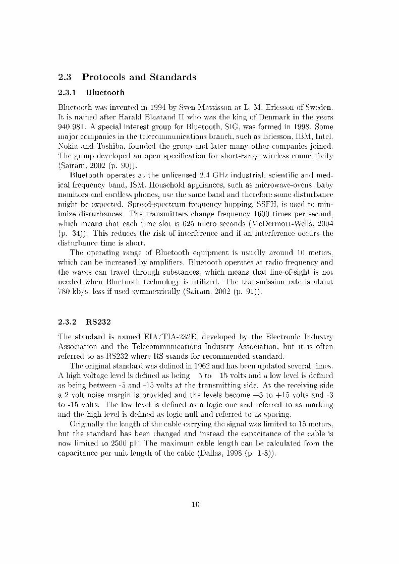
Bluetooth was invented in 1994 by Sven Mattisson at L. M. Ericsson of Sweden.It is named after Harald Blaatand II who was the king of Denmark in the years940-981. A special interest group for Bluetooth, SIG, was formed in 1998. Somemajor companies in the telecommunications branch, such as Ericsson, IBM, Intel,Nokia and Toshiba, founded the group and later many other companies joined.The group developed an open speci�cation for short-range wireless connectivity(Sairam, 2002 (p. 90)).
Bluetooth operates at the unlicensed 2.4 GHz industrial, scienti�c and med-ical frequency band, ISM. Household appliances, such as microwave-ovens, babymonitors and cordless phones, use the same band and therefore some disturbancemight be expected. Spread-spectrum frequency hopping, SSFH, is used to min-imize disturbances. The transmitters change frequency 1600 times per second,which means that each time slot is 625 micro seconds (McDermott-Wells, 2004(p. 34)). This reduces the risk of interference and if an interference occurs thedisturbance time is short.
The operating range of Bluetooth equipment is usually around 10 meters,which can be increased by ampli�ers. Bluetooth operates at radio frequency andthe waves can travel through substances, which means that line-of-sight is notneeded when Bluetooth technology is utilized. The transmission rate is about780 kb/s, less if used symmetrically (Sairam, 2002 (p. 91)).
2.3.2 RS232
The standard is named EIA/TIA-232E, developed by the Electronic IndustryAssociation and the Telecommunications Industry Association, but it is oftenreferred to as RS232 where RS stands for recommended standard.
The original standard was de�ned in 1962 and has been updated several times.A high voltage level is de�ned as being +5 to +15 volts and a low level is de�nedas being between -5 and -15 volts at the transmitting side. At the receiving sidea 2 volt noise margin is provided and the levels become +3 to +15 volts and -3to -15 volts. The low level is de�ned as a logic one and referred to as markingand the high level is de�ned as logic null and referred to as spacing.
Originally the length of the cable carrying the signal was limited to 15 meters,but the standard has been changed and instead the capacitance of the cable isnow limited to 2500 pF. The maximum cable length can be calculated from thecapacitance per unit length of the cable (Dallas, 1998 (p. 1-8)).
10

Figure 3: Pinout for 25 and 9 pins connectors (Strangio, 2006).
The RS232 standard speci�es a 25 pin connector, but because many applicationsdo not use all of the signals speci�ed, versions with 15 or 9 pins can be usedinstead. The 9 pin connector is enough to transmit and receive the necessarysignals for modem applications. A comparison of signals sent in a 25 and 9 pinconnector is shown in Figure 3. The 9 pin connector is used in this project.
2.3.3 AT Commands
AT comes from the word attention. The original AT commands were de�nedby Dennis Hayes, his commands all began with the letters AT and thereforethe naming. These were used with modems and made it possible to use onlyone communication channel by shifting between data mode and command mode,otherwise two channels were needed. The command language has grown and nowincludes commands for data, fax, voice and SMS communications (Bies, 2008b).
Even though the command set used for the Bluetooth chip in this projectis similar to other AT command sets, it is implemented especially for EZURiOsBluetooth devices (Ezurio, 2006 (p. 4)).
11
2.3.4 UART
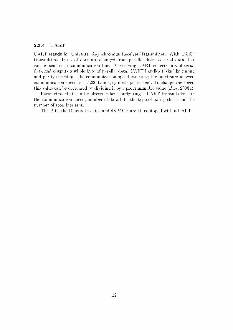
UART stands for Universal Asynchronous Receiver/Transmitter. With UARTtransmitters, bytes of data are changed from parallel data to serial data thatcan be sent on a communication line. A receiving UART collects bits of serialdata and outputs a whole byte of parallel data. UART handles tasks like timingand parity checking. The communication speed can vary; the maximum allowedcommunication speed is 115200 bauds, symbols per second. To change the speedthis value can be decreased by dividing it by a programmable value (Bies, 2008a).
Parameters that can be altered when con�guring a UART transmission arethe communication speed, number of data bits, the type of parity check and thenumber of stop bits sent.
The PIC, the Bluetooth chips and dSPACE are all equipped with a UART.
12

2.4 The Microcontroller
The controller used in this project is PIC16F73 from Microchip referred to asPIC in this report. The PIC has the operating frequency of 20MHz. It can beprogrammed using the C programming language - the instruction set in the datasheet is however given in assembly language that can also be used. Various de-velopment tools are available that can be used with the PIC, such as a compilersand editors.
The UART port on the PIC is used to connect to the Bluetooth chip. Incom-ing measurements arrive through the on-chip A/D converter and digital ports areused to forward control signals to the transporter via a D/A converter. Whenthe DC-motor control is applied the PWM output is used instead of the digitaloutput and the D/A converter.
2.4.1 Communication with Bluetooth
The communication with the Bluetooth transceiver is done through the UARTport on the PIC. The UART communication is in full duplex mode; that isinformation is sent and received through the UART port on the PIC.
The UART consists of four elements; a baud rate generator, a sampling circuit,an asynchronous transmitter and an asynchronous receiver. An on-chip 8 bitbaud rate generator is used to derive standard baud rate frequency from anoscillator. The sampling circuit samples the input three times and a majoritycheck determines if the value should be high or low (Microchip, 2002 (p. 71-73)).
Figure 4: A block diagram of the transmitter (Microchip, 2002 (p. 73)).
The operation of the asynchronous transmitter is shown in Figure 4. A transmitbu�er, TXREG, is used to insert data from software. The data to be sent isforwarded from TXREG and loaded in the transmit shift register, TSR. During
13
transmission the data is further forwarded to the TX output-pin with the leastsigni�cant bit �rst. When the last bit, the stop bit, has been transmitted thenew content of TXREG is loaded into the TSR. One instruction cycle later a �ag,TXIF, is set and TXREG can be reloaded. The �ag is cleared when TXREG hasbeen loaded again. The �ag can be used to determine whether the data bu�eris empty or full. Another �ag, TMRT, shows the status of the TSR. To enabletransmission the TXEN bit has to be set. Transmission takes place after TXENhas been set, TXREG has been loaded and a shift clock has been produced bythe baud rate generator. Usually the TSR is empty when transmissions begin(Microchip, 2002 (p. 73-74)).
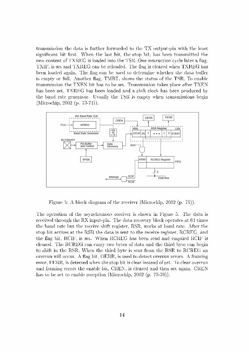
Figure 5: A block diagram of the receiver (Microchip, 2002 (p. 75)).
The operation of the asynchronous receiver is shown in Figure 5. The data isreceived through the RX input-pin. The data recovery block operates at 64 timesthe baud rate but the receive shift register, RSR, works at baud rate. After thestop bit arrives at the RSR the data is sent to the receive register, RCREG, andthe �ag bit, RCIF, is set. When RCREG has been read and emptied RCIF iscleared. The RCREG can carry two bytes of data and the third byte can beginto shift in the RSR. When the third byte is sent from the RSR to RCREG anoverrun will occur. A �ag bit, OERR, is used to detect overrun errors. A framingerror, FERR, is detected when the stop bit is clear instead of set. To clear overrunand framing errors the enable bit, CREN, is cleared and then set again. CRENhas to be set to enable reception (Microchip, 2002 (p. 75-76)).
14

2.4.2 Analog Input
The PIC is equipped with 5 analog inputs and one 8 bit A/D converter as shownin Figure 6. The on-chip A/D converter works with one input at a time, theinput channel is selected before conversions.
Figure 6: A block diagram of the analog input (Microchip, 2002 (p. 85)).
A capacitor is charged to the voltage level of the input channel. It is importantto give the capacitor su�cient time to charge so that the analog input will beaccurate. When the enable bit, ADGO, is set the A/D conversion begins. Whenthe conversion is complete the ADGO bit is cleared, the ADIF �ag is set and the8 bit digital number can be found in the result register, ADRES. The ADGO bitcan be set again. The reference voltage can be the same as the supply voltage forthe PIC or set on a de�ned input pin that is otherwise used as an analog input(Microchip, 2002 (p. 83-87)).
2.4.3 Analog Output
The PIC does not have an analog output, instead a digital output and a D/Aconverter are used. The D/A converter used is AD7303 from Analog Devices.The D/A converter receives three signals from the PIC; one for data, another onefor a clock signal and the third one to enable data input.
15

Figure 7: A block diagram of the D/A converter (Analog, 1997 (p. 1)).
The function of the converter is shown in Figure 7. The input shift register isenabled when SYNC is cleared, then data bits are transferred via the data pin,DIN, on the rising edges of the serial clock, SCLK. The shift register contains16 bits, 8 bits are for the control of the D/A converter and the other 8 bits arethe data bits that will be converted. The voltage reference can be the same asused for the chip or set at an input, REF. The output channel is chosen with thecontrol bits, either A or B is used (Analog, 1997 (p. 1-4)).
2.4.4 Pulse Width Modulation
The PIC has a pulse width modulation, PWM, module. The module is used tocreate output when controlling a DC motor.
Figure 8: PWM signal (Microchip, 2002 (p. 57)).
A timing diagram of a PWM signal is shown in Figure 8. The duty cycle canvary between 0% and 100% of the period. The full voltage is seen at 100% andnone at 0%. The PMW frequency is the reciprocal of the period.
16

Figure 9: PWM block diagram (Microchip, 1997 (p. 14-8)).
The operation of the PWM module is shown in Figure 9. One of the timers inthe PIC, TMR2, is used together with the PWM module. The desired PWMperiod is written to register PR2. The value for the duty cycle is written to theCCPR1L register and bits 4 and 5 of the CCP1CON register, 10 bits in total.It is forwarded to CCPR1H and a 2-bit internal latch when PR2 and TMR2become equal. At this time TMR2 is cleared and the CCP1 output-pin is set.When TMR2 is equal to the contents of CCPR1H and the 2-bit latch the CCP1output-pin is cleared (Microchip, 1997 (p. 14-8�14-11)).
A multifunction PIC board that is available at the department is used in thisproject. This board consists of a PIC, D/A converters, LCD screen and otherintegrated circuits that can be used with the PIC. A diagram for this board isshown in Appendix C.
2.5 The Bluetooth Chip
The chips used for Bluetooth communication are the BISM2 Bluetooth Version2.0 Serial Modules from EZURiO. The range of the chip is listed as 300 m, andthe transmission speed up to 300 kb/s (Ezurio, 2009). One chip is located at thecomputer and another one at the transporter. Each Bluetooth chip has a uniqueaddress, a 12 digit hexadecimal string that is used to identify it. The chip is set upand controlled with AT-commands. The chips can operate in three modes; datamode to send information, local command mode to set up and control the chipor remote command mode to receive commands through a Bluetooth connection(Ezurio, 2006 (p. 4)).
This chip is used because it has been successfully used in another wirelessproject at the department.
17

2.6 MAX232
Maxim's MAX232 chip is used as a link between the Bluetooth chip and theRS232 interface. The RS232 interface operates with voltage in the range of -10to 10 volts but the Bluetooth chip operates at 0 to 5 volts. The MAX232 chiptranslates the signals between the Bluetooth chip and the RS232 communicationinterface. The de�nition of high and low is reversed and the voltage is altered.
Figure 10: Pinout and functional diagram for MAX232 (Maxim, 2006 (p. 17)).
The MAX232 consists of three sections: dual charge-pump DC-DC voltage con-verters, RS232 drivers and RS232 receivers (Maxim, 2006 (p. 14)). The pinoutand the function of MAX232 can be viewed in Figure 10.
2.7 dSPACE
dSPACE is a development tool, which consists of both a hardware and a softwarepart. The software used in this project is ControlDesk where signals can beviewed and parameters changed. The hardware, DS1104 R&D controller board,is a digital signal processor that translates incoming and outgoing signals inreal time. The board is connected to the PC via a PCI bus. Systems can beimplemented in C and run in real time (dSPACE, 2009 (p. 332)).
A model of the system is constructed in Simulink with the help of Real-TimeInterface, RTI, and then translated into C programming code for the ControlDeskin dSPACE. All improvements of the controller are carried out in Simulink.
18
2.8 Other Tools
Some other tools are used in the project and are mentioned in the report. Ashort explanation follows for these.
• Hyper Terminal is a terminal emulation program that is run at the com-puter. It is used to connect to devices via COM ports.
• All-11 is a programming device from Hi Lo systems. It is used to translateincoming code to voltages so that the PIC can be programmed.
• Waccess is the software used for programming the PIC. It communicateswith All-11.
• MPLAB IDE, software from Microchip. It is used to write and compile Ccode for the PIC.
• Simulink is a program within Matlab. It is used to design the system usingexisting customizable blocks.
• Real-Time Interface, RTI, supplies Simulink with input and output blocksthat can be used with dSPACE.
• DC-motor, a 12 V brushed direct current motor is used in the project.
• H-bridge, a circuit to regulate and amplify the control signals for the DC-motor.
• Gyroscope, used to measure angular momentum.
• Accelerometer, used to measure angular velocity.
19

3 Implementation
3.1 Connections
The connection of the equipment is shown in Figure 11. The Bluetooth transceiveris connected to a dSPACE controller board via a serial connection. The se-rial RS232 connector has to be translated to be able to communicate with theBluetooth transceiver. A MAX232 adapter is used to do this. The informationtravels through air to the other Bluetooth transceiver and onwards to a PIC-microcontroller via a MAX232 adapter. The measurements from the transporterare received via an analog input of the PIC and a D/A converter is used totranslate the digital control signal to an analog signal for the transporter.
Figure 11: The connection between dSPACE and the transporter
3.1.1 Veri�cation of Connections
The work begins with the setup of the MAX232 adapter chip. The signal con-version is veri�ed with measurements using a voltmeter; these are compared tothe data sheet and proved to be right. Afterwards the chip is connected to acomputer via the serial interface. Characters are sent from the Hyper Terminalat the computer and the translation is veri�ed by viewing bits on an oscilloscopeand comparing them to the ASCI code for the sent character.
The next step is to connect the Bluetooth chip to the remote side of theMAX232 chip. Transmission are still controlled by the Hyper Terminal but nowAT commands are sent to the Bluetooth chip. The Bluetooth chip is made visibleand connectable. For veri�cation a connection with a Bluetooth enabled mobilephone is made, this connection is not used in the project.
The PIC is now con�gured and connected. The PIC board is equipped with anLCD screen, which is used to display characters. This screen is very useful whenverifying the operation of the PIC. At �rst the connection between the computerand the PIC is veri�ed, characters sent from the computer are displayed at the
20
screen successfully. Later on the computer is unplugged and instead the Blue-tooth chip is connected to the PIC via the MAX232 adapter. Preprogrammed ATcommands are sent from the PIC to the Bluetooth chip that becomes visible andconnectible. For further veri�cation a character is displayed at the LCD screenat certain steps in the programming.
A connection is then set up between the two Bluetooth transceivers. Thisturned out to be quite straight forward and the chips are con�gured so that theyautomatically connect at power up.
The �nal part of the connection process is to communicate with dSPACE.One of the Bluetooth chips is connected to dSPACE and after some tuning ofparameters communication is established with dSPACE.
3.2 The Bluetooth Chips
The Bluetooth chips are controlled by AT commands. Hyper Terminal is used tocommunicate with the chips. After a command is given at Hyper Terminal, theBluetooth chip replies with some preprogrammed feedback like OK or ERROR.The commands are easily understood and well explained in a listing provided onEZURiO's website. The chips are programmed to connect at start up.
One of the chips is the master and the other one a slave. In this setup it doesnot matter which transceiver is the slave and which one is the master. By defaultthe master is connectable but not discoverable, that is it can only be connectedto by equipment that already have its address. The same settings were chosenfor the slave. When the Bluetooth chips are turned on the master looks for theslave and a connection is made. If the connection can not be made the mastertries to connect to the slave again after a waiting period of 2 sec. This time is setby AT commands. When a connection has been made all the information thatis received on the transceivers UART ports is forwarded to the other transceiver.This is the same for both the chips.
Explanation of AT commands can be found in Appendix A.
3.3 The PIC
The PIC is programmed using the C programming language. The C code is com-piled and the output is stored in a HEX �le that can be translated with Waccesssoftware and then programmed to the PIC with an All-11 programmer.
The code is divided in �ve separate C-�les. One �le includes the main func-tion, the second �le contains functions for the UART port, the third �le functionsfor the A/D and D/A conversion, the fourth �le functions for PWM and the �fth�le functions for the LCD screen. The main function is run when the PIC isturned on and other functions are activated from within the main function. Thecode could have been written in one �le, however, the division is done to have
21

better overview of the programming.
In the main function the setup of di�erent ports and values is carried out andthen a while loop is repeated until the equipment is turned o�. In this loop theinterrupt �ags for incoming UART signal and incoming analog signal are checked.
If a UART signal is detected, two functions are started. The �rst functionretrieves the incoming control signal. If the output should be an analog signalthe second function forwards a digital output and conversion control values tothe D/A converter. If the output should be a PWM signal the second functiondetermines the direction of which the motor should rotate and forwards a valueto the PMW module. The analog conversion (ADGO) is set at the end of thisloop.
If an analog signal is detected, the �rst function retrieves the signal andthe second one forwards it to the outgoing UART port. The sampling of theanalog signal can be continuous, but in order to limit the sampling speed to thetransmission speed the A/D conversion is turned on after a UART signal hasbeen detected.
The code for the PIC can be found in Appendix B.
3.4 Working with dSPACE
The Control Desk in dSPACE is used to view the signals. A model is built inMatlab Simulink and translated to C-code to work with dSPACE.
Figure 12: The layout in Simulink.
The layout for the motor control in Simulink is shown in Figure 12. Most of theblocks are ordinary Simulink blocks but three of the blocks come from the RTI.These are the blocks that represent the UART. One represents the received signal,
22

one the transmitted signal and the third one is used to control the transmissionspeed and other settings for UART. These blocks require an input of the formunsigned 8 bit integer, uint8.
23

Figure 13: The layout in dSPACE.
The setup for the motor control in dSPACE is shown in Figure 13. The referenceis set with the button at the upper left corner of the layout. The measurementfrom the motor is viewed at the meter that is located besides the button. Theparameters for the PID controller can be changed and viewed in the upper rightcorner. The error value, the output from the PID controller and the control signalare shown below the PID parameters. The graph displays the reference value andthe measurements from the motor.
Below the layout �gure a listing of variables is found. Parameters markedwith P can be changed at any time in dSPACE. Other variables are incomingsignals or outcomes of functions that can be viewed.
24
4 Conclusions
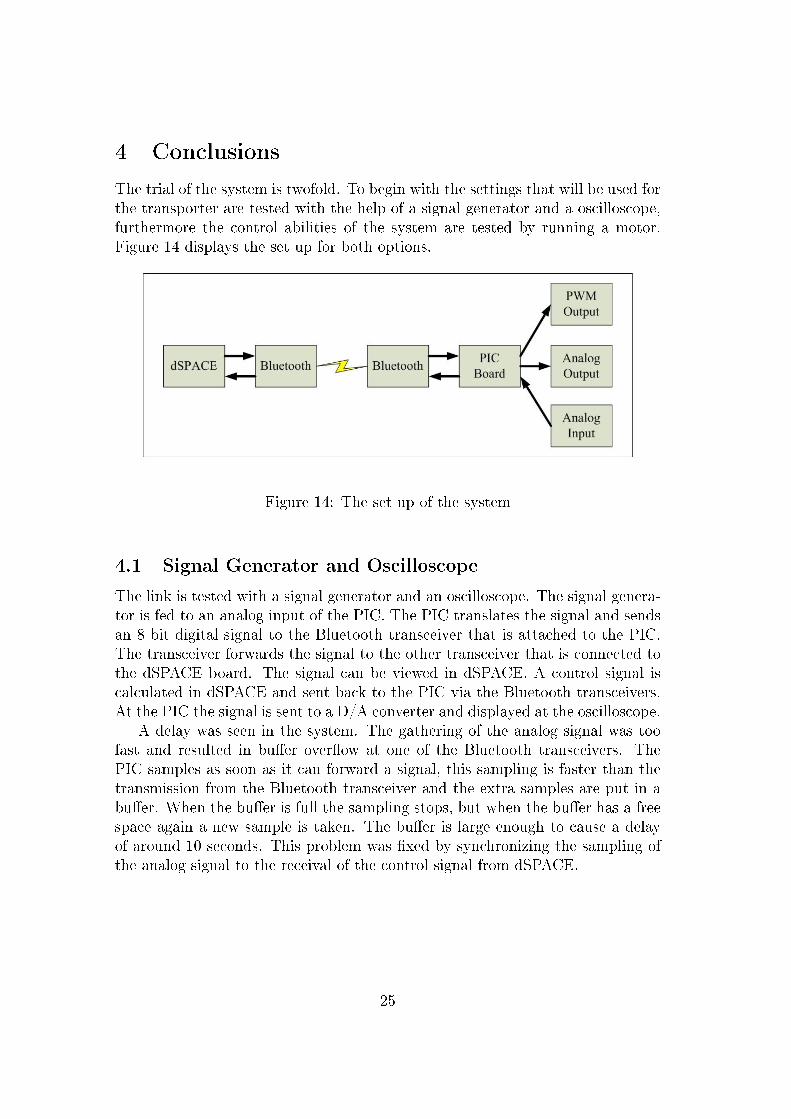
The trial of the system is twofold. To begin with the settings that will be used forthe transporter are tested with the help of a signal generator and a oscilloscope,furthermore the control abilities of the system are tested by running a motor.Figure 14 displays the set up for both options.
Figure 14: The set up of the system
4.1 Signal Generator and Oscilloscope
The link is tested with a signal generator and an oscilloscope. The signal genera-tor is fed to an analog input of the PIC. The PIC translates the signal and sendsan 8 bit digital signal to the Bluetooth transceiver that is attached to the PIC.The transceiver forwards the signal to the other transceiver that is connected tothe dSPACE board. The signal can be viewed in dSPACE. A control signal iscalculated in dSPACE and sent back to the PIC via the Bluetooth transceivers.At the PIC the signal is sent to a D/A converter and displayed at the oscilloscope.
A delay was seen in the system. The gathering of the analog signal was toofast and resulted in bu�er over�ow at one of the Bluetooth transceivers. ThePIC samples as soon as it can forward a signal, this sampling is faster than thetransmission from the Bluetooth transceiver and the extra samples are put in abu�er. When the bu�er is full the sampling stops, but when the bu�er has a freespace again a new sample is taken. The bu�er is large enough to cause a delayof around 10 seconds. This problem was �xed by synchronizing the sampling ofthe analog signal to the receival of the control signal from dSPACE.
25

4.2 Motor Control
A DC motor is controlled with the Bluetooth link. The input to the PIC remainsthe same, the output is now a PWM signal. The PWM signal is forwarded to aH-bridge and then to the DC motor. A variable resistance is used to measure thevelocity of the DC motor and that signal is fed to the analog input on the PIC.The communication with dSPACE remains unchanged.
A di�erent delay was seen with this setup. The control signal is delayed onthe way to the PIC. The sample time in dSPACE is too high and the controlsignal is put in a bu�er on the way to the PIC. This is �xed by adjusting thesample time in Simulink.
4.3 Measurements
The transmission time from the input of one Bluetooth chip to the output of theother is 24 ms, the frequency is 41.6 Hz. The measurements were made with anoscilloscope.
The range of the chips was also tested and connection was lost at about 40m, the connection could be reset at around 20 m.
26

5 Future Work
The link can be used for communication, and is su�cient for the motor control.Future work includes more channels for communication, improved set up of thecircuits and to add a portable power supply.
Future work for the Segway task includes the following:
• Improved control
• Connection to the transporter
When a transporter is operated various security issues will have to be dealt with.How should it behave when the battery runs out? What should be done whenthe maximum speed is reached? How fast should it accelerate and slow down?What happens if the driver falls o� when the transporter is moving? These andmany more issues will have to be con�gured in the control.
27
6 References
Analog Devices (1997), +2.7 V to +5.5 V, Serial Input, Dual Voltage Output8-Bit DAC, One Technology Way, Massachusetts, USA.
Bies, L. (April 2008a), Serial UART, an in depth tutorial, http://lammertbies.nl-/comm/info/serial-uart.html, 21. October 2009.
Bies, L. (April 2008b), Hayes modem AT commands, http://lammertbies.nl/comm-/info/hayes-at-commands.html, 21. October 2009.
Dallas Semiconductor (1998), Application Note 83, Fundamentals of RS-232Serial Communications.
dSPACE (2009), Catalog 2009, dSPACE, Paderborn, Germany.
EZURiO Limited (2006), EZURiO, AT command set.
EZURiO Limited (2009), EZURiO, Bluetooth Intelligent Serial Module, http://-www.ezurio.com/products/bism/, 13. October 2009.
Forouzan, B. A. (2003), Data Communications and Networking third edition,McGraw-Hill, New York.
Maxim Integrated Products (2006), Maxim, +5V-Powered, Multichannel RS-232Drivers/Receivers, Maxim Integrated Products, California.
McDermott-Wells, Patricia (2004), What is Bluetooth?, IEEE Potentials,December2004/January2005, p. 33-35.
Microchip Technology Inc (2002), PIC16F7X, Data Sheet, U.S.A.
Microchip Technology Inc (1997), PICmicro, Mid-Range MCU Family,Reference Manual, U.S.A.
Sairam, K.V.S.S.S.S.- Gunasekaran, N. - Rama Reddy, S. (2002), Bluetooth inWireless Communication, IEEE Communications Magazine,June 2002, p. 90-96.
Sandberg, Anders - Westman, Bengt (2007), Report Balancing scooter project,IEA, Sweden.
28

Segway Inc. (2008a), Explore Models, http://www.segway.com/individual/models/-index.php, 29. September 2008.
Segway Inc. (2008b), How the Segway PT Works, http://www.segway.com/indi-vidual/learn-how-works.php, 22. October 2009.
Segway Inc. (2008c), Segway Milestones, http://www.segway.com/about-segway/-segway-milestones.php, 29. September 2008.
Segway Inc. (2008d), Simply Moving, Segway Product Brochure.
Strangio, Christopher E. (2006), The RS232 Standard, CAMI Research Inc.,Massachusetts, http://www.camiresearch.com/Data_Com_Basics/RS232_-standard.html#anchor341671, 9. Oktober 2009.
29

7 Appendix
A AT Commands
This list contains some of the commands used in the project and a short expla-nation. Full documentation on the AT commands can be found on EZURiO'swebsite.
ath drop an existing connection.
ati4 returns a 12 digit hexadecimal Bluetooth address
ats0 number of RING indication before automatically answering an incoming connection
ats504 suppresses messages arising from connections or pairing
ats507 con�gure how connection is dropped
ats512 speci�es power up state
ats520 change to a standard baud rate
ats530 reconnect delay when con�gured as master in pure-cable-replacement mode
at&f* clear non-volatile memory
at&w write to non-volatile memory
at+btr set outgoing peer address
at+btt add trusted device
30

B PIC Programming Code
B.1 main
#include <pic.h>
#include "header.h"
#include "delay.h"
#include "forLCD.c"
#include "forUART.c"
#include "forAD.c"
#include "forPWM.c"
__CONFIG(0x5a); //PIC16F73
void DelayMs(unsigned char ccnt)
{
unsigned char i, cnt;
cnt = ccnt;
do {
i = 4;
do {
DelayUs(250);
} while(--i);
} while(--cnt);
}
void DelayS(unsigned char ccnt)
{
unsigned char i, cnt;
cnt = ccnt;
do {
i = 4;
do {
DelayMs(250);
} while(--i);
} while(--cnt);
}
void adrPort(int adr){
switch(adr){
case 4:
RC0=0;
RC1=0;
31

RA3=1;
break;
case 2:
RC0=0;
RC1=1;
RA3=0;
break;
case 0:
RC0=0;
RC1=0;
RA3=0;
break;
}
}
// Define function of the pins I/O
void setupPorts()
{
TRISA = 0xef; //1110 0111
TRISB = 0; //0000 0000
TRISC = 0x80; //1000 0000
}
void main()
{
char ctrlSignal, measuredValue;
// Define ports
setupPorts();
// Setup the LCD display
setupLCD();
// Setup analog digital conversion
setupAD();
// Setup PWM
setupPWM();
// Display message, mostly used to verify updates
//msgLCD();
msgOK();
// Set up the UART connection
setupUART();
DelayS(4);
ADGO=1;
while(1)
32

{
// If RCIF, data on UART forwarded to D/A
if(RCIF)
{
ctrlSignal=rxUART();
// Output as analog signal
//sendDA(ctrlSignal);
// Output as PWM
setPWM(ctrlSignal);
ADGO=1;
}
// If ADIF, data on A/D forwarded to UART
if(ADIF & TXIF)
{
measuredValue=getAD();
txUART(measuredValue);
}
}
}
B.2 forLCD
// Send control commands to the screen
void LCDControl(char ctrl) //Control
{
LCDbus = ctrl;
RS = 0;
//AdrPort=LCDadr;
adrPort(0);
AdrEnable = 1;
DelayUs(50);
AdrEnable = 0;
DelayUs(4);
}
// Configure the LCD screen
void setupLCD()
{
DelayMs(20);
LCDControl(FunctionSet);
DelayMs(10);
LCDControl(FunctionSet);
DelayMs(5);
33

LCDControl(FunctionSet);
DelayMs(5);
LCDControl(FunctionSet);
DelayMs(5);
LCDControl(EntryModeSet);
DelayMs(5);
LCDControl(DisplayOff);
DelayMs(5);
LCDControl(DisplayClear);
DelayMs(10);
LCDControl(DisplayOn);
DelayMs(20);
}
// Display a character on LCD screen
void LCDWrite(char write)
{
LCDbus = write;
RS = 1;
adrPort(LCDadr);
DelayUs(40);
AdrEnable = 1;
DelayUs(40);
AdrEnable = 0;
DelayUs(4);
}
void msgLCD()
{
LCDWrite('A');
LCDWrite('A');
//LCDWrite('');
}
void msgOK()
{
// Write on the lower line of the display
LCDControl( LowerLine );
LCDWrite('O');
LCDWrite('K');
//Return the cursor on the upper line
LCDControl( UpperLine );
}
34
B.3 forUART
// Configure UART on PIC
void setupUART()
{
SPBRG=129; //Valid for high speed, 20MHz and 9600 Baud
BRGH=1; //1 for High speed, 0 for Low speed
SYNC=0; //1 for synchronous, 0 for asynchronous
SPEN=1; //Enable the pins for the serial ports
TXIE=0; //Transmission interrupts. 0 for disable, 1 for enable
RCIE=0; //Reception interrupts. 0 for disable, 1 for enable
TX9=0; //Transmission : 1 for nine bits, 0 for eight
RX9=0; //Reception : 1 for nine bits, 0 for eight
TXEN=1; //Enable transmission
CREN=1; //Enable reception
}
// Send via Bluetooth (UART)
void txUART(char prufa)
{
//int j=0;
while(!TXIF)
{
//Do nothing, just wait
}
TXREG=prufa;
}
// Receive via Bluetooth (UART)
char rxUART()
{
char temp;
// Check for framing error and reset
if(FERR)
{
LCDWrite('F');
CREN=0;
CREN=1;
}
// Check for overfull error and reset
if(OERR)
{
LCDWrite('O');
35
CREN=0;
CREN=1;
}
temp=RCREG;
return temp;
}
B.4 forAD
// Configure A/D converter on PIC
void setupAD()
{
ADCON1=0x04; // U U U U U PCFG2 PCFG1 PCFG0
ADCON0=0x81; // ADCS1 ADCS0 CHS2 CHS1 CHS0 GO/DONE U ADON
ADIF=0; //Flag bit for incoming A/D
}
// Get A/D input
char getAD()
{
char temp;
temp=ADRES;
ADIF=0;
return temp;
}
// Forward bits to D/A chip
void outDA(char out)
{
char i, sr;
sr=out;
for (i=0; i<8; i++)
{
// Send the MSB and then shift
if ((sr & 0x80) == 0)
DAdat=0;
else
DAdat=1;
// Bits are loaded on clocks rising edge
DAclk=1;
sr = sr<<1;
DAclk=0;
}
36

}
// Send D/A output, data and control signal for inverter
void sendDA(char DA)
{
char ControlBits=0x03; // Channel A/B - 3/7
char DataBits=DA;
DAdat=0;
DAclk=0;
//AdrPort=DA0adr;
adrPort(4); // D/A chip U107/U109 - 4/5
AdrEnable = 1;
outDA(ControlBits);
outDA(DataBits);
AdrEnable = 0;
}
B.5 forPWM
// Configure PWM on PIC
void setupPWM()
{
PR2=0xC7; //PWM frequency 50 kHz, 20 uS
CCPR1L=0x80; //Begin with half duty cycle
CCP1CON=0x0C; //0000 1100 PWM mode, the two lsb=0
T2CON=0x04; //Timer prescaler =1, timer2on
}
// Set the PWM duty cycle
void setPWM(char value)
{
char enable;
char pwm = value; // 0<=value<=255
// Set direction and
if((pwm & 0x80) == 0) // 0<=value<=127
{
enable=0x80-pwm; //1<=enable<=128
DIN1=0;
DIN2=1;
if((pwm & 0x80) == 0)
{
enable=0x7F;
}
37
}
else // 128<=value<=255
{
enable=pwm-0x80; // 0<=enable<=127
DIN2=0;
DIN1=1;
}
//AdrPort=DOUTadr;
adrPort(2);
AdrEnable=1;
enable=enable<<1; // 0<=enable<=254 (step 2)
CCPR1L=enable;
AdrEnable=0;
}
38

C The Multifunction PIC Board
R11
3
10k
10k
R104
12
34
56
78
9
GN
D
J109
12
34
56
78
910
J103
:33
U10
5
SN
74H
C24
5NB8
11B
712
B6
13B
514
B4
15B
316
B2
17B
118
A8
9A
78
A6
7A
56
A4
5A
34
A2
3A
12
DIR
1G
19
U10
6
SN
74H
C27
3N8Q
197Q
166Q
155Q
124Q
93Q
62Q
51Q
2
8D18
7D17
6D14
5D13
4D8
3D7
2D4
1D3
CLK
11C
LR
1
GN
D
VC
C
J103
:11
J103
:22
CO
MB
IC38
1X5
J103
:55
J103
:44
J102
:33
J102
:55
CO
MB
IC38
1X8
J102
:88
J102
:77
J102
:66
J102
:44
J102
:22
J102
:11
J105
:33
J105
:55
CO
MB
IC38
1X8
J105
:88
J105
:77
J105
:66
J105
:44
J105
:22
J105
:11
CO
MB
IC38
1X5
J107
:55
J107
:44
J107
:33
J107
:22
J107
:11
J104
:11
J104
:22
J104
:33
J104
:44
J104
:55
J104
:66
J104
:77
J104
:8
CO
MB
IC38
1X8
8
U10
9
AD
7303
SC
LK5
DIN
6
SY
NC
7
RE
F4
VO
UT
B8
VO
UT
A1
GN
D3
VD
D2
U10
7
AD
7303
SC
LK5
DIN
6
SY
NC
7
RE
F4
VO
UT
B8
VO
UT
A1
GN
D3
VD
D2
GN
D
GN
D
10k
R101
U10
2
PIC
16F
873
OS
C1/
CLI
9
OS
C2/
CLO
10
RB
728
RB
627
RB
526
RB
425
RB
324
RB
223
RB
122
RB
0/IN
T21
RC
0/T
1OO
/T1C
I11
RC
1/T
1OI/C
CP
212
RC
2/C
CP
113
RC
3/S
CK
/SC
L14
RC
4/S
DI/S
DA
15R
C5/
SD
O16
RC
6/T
X/C
K17
RC
7/R
X/D
T18
MC
LR
/V
PP
1
RA
0/A
N0
2R
A1/
AN
13
RA
2/A
N2
4R
A3/
AN
3/V
RE
F5
RA
4/T
0CK
I6
RA
5/
AN
4/
SS
7
10k
R102
VC
C
JP10
31 2
GN
D
X10
1
VA
L
15p
C103
15p
C104
GN
D
GN
D
VC
C
MA
X23
2CP
E
U10
4
V+
2
V-
6
T1O
UT
14
T2O
UT
7
R1I
N13
R2I
N8
R2O
UT
9R
1OU
T12
T2I
N10
T1I
N11
C2-
5
C2+
4
C1-
3
C1+
11.
5u/1
6
C10
1
1.5u
/16
C10
6
1.5u
/16
C10
2
1.5u
/16
C10
5
JP106
12
JP107
12
VC
C
24LC
64/P
U10
8 WP
7
A0
1
A1
2
A2
3S
CL
6
SD
A5
GN
D
R10
5
4k7
R10
6
4k7
VC
C
J101
DB
9F
987654321
U10
1
SN
74H
C13
8N Y7
7
Y6
9
Y5
10
Y4
11
Y3
12
Y2
13
Y1
14
Y0
15
G2
B5
G2
A4
G1
6
C3
B2
A1
JP10
1
3
2
1 JP10
2
3
2
1 JP10
4
3
2
1 JP10
5
3
2
1
GN
D
SN
7517
6N
U11
1
A6
B7
RE
2
D4
DE
3
RD
1
JP11
03
2
1
C115
VAL
R11
0
10k
R11
4
10k
R11
1
10
R11
2
10V
CC
GN
D
B10
1
D7
1
D6
2
D5
3
D4
4
D3
5
D2
6
D1
7
D0
8E
9
R/
W10
RS
11
VLC
12
GN
D13
VC
C14
VC
C
GN
D
10k
R103
C W
W
C C W
U10
3
SN
74H
C24
5NB8
11B
712
B6
13B
514
B4
15B
316
B2
17B
118
A8
9A
78
A6
7A
56
A4
5A
34
A2
3A
12
DIR
1G
19
VC
C
U11
2:A
SN
74H
C04
D21
U11
2:B
SN
74H
C04
D43
U11
2:C
SN
74H
C04
D65
U11
2:D
SN
74H
C04
D89
U11
2:E
SN
74H
C04
D1011
U11
2:F
SN
74H
C04
D1213
R11
5
10k
R11
6
10k
VC
C
J110
:11
J110
:22
J110
:33
GN
D
JP11
1
1
2
3
+24
V
GN
D
CO
MB
IC38
1X5
J106
:55
J106
:44
J106
:33
J106
:22
J106
:11
10u/25V
C112
100n
C107
100n
C108
100n
C109
100n
C110
100n
C111
GN
D
D1011N4004
VC
C
GN
D
VC
C
J111
:11
J111
:22
J111
:33
J111
:44
J111
:55
VC
C
BA
L74
D10
2
JP10
8
1
2
3
10k
R10
7
2k2
R10
8
GN
D
VC
C
Q10
1
BC
X53
GN
DR10
9
22R
J108
:1
1 2
Mon
Oct
22
2007
Prin
ted:
Bak
light
er c
ontr
ol
Par
alle
l in
Par
alle
l out
D/A
out
put
PP
73A
.S01
GL
11
Mul
tifun
ctio
n P
IC16
X(X
)73
boar
d
RS
232
Por
t
Ser
ial E
EP
RO
M
2006
-06
/ 200
1
06a
Pus
hbut
ton
inte
rfac
e
D7
D6
D5
D4
D3
D2
D1
D0
D7
D6
D5
D4
D3
D2
D1
D0
CE
DA
1
CE
DA
0
CE
DI
LCD
RS
AN
4
AN
3A
N2
AN
1A
N0
MC
LR
D7
D6
D5
D4
D3
D2
D1
D0
RS
232R
XR
S23
2TX
SC
LS
DA
RS
232T
X
D1
D0
D1
D0
CE
DO
CE
PB
UT
CE
DO
CE
DI
CE
DA
0C
ED
A1
PIC
RC
5
AN
1
AN
2
AN
3
AN
4
AN
4A
N3
AN
2A
N1
AN
0
SC
L
SD
A
RS
232R
X
D7
D6
D5
D4
D3
D2
D1
D0
CE
LCD
LCD
RS
D0
D1
D2
D3
D4
D5
D6
D7
CE
PB
UT
CE
LCD
PIC
RC
5
AN
4
MC
LR
D7
D6
AN
4
AB
CD
EF
4321
FE
DC
BA
1 2 3 4
A2
Rev
Num
ber
Titl
e
Siz
e
Dat
e
File
nam
e
Dra
wn
by
ofS
heet
The board contains a microcontroller, LCD screen and other integrated cir-cuits that are frequently used together with the controller. This board is verygood to have under the development phase of a project.
39