Embed Size (px)
Citation preview

Wired M-Bus Modules for MULTICAL® 403 and 603
• For billing, analysis and controlling purposes
• Configurable datagrams
• Readout of loggers
• Up to 19200 baud communication speed
• Primary/secondary/enhanced secondary addressing
• Two pulse inputs, two pulse outputs or Thermal Disconnect
• Remote software update
• According to M-Bus standard EN 13757:2013
• According to OMS TR02:2015
Data sheet

2 Kamstrup A/S • 58101450_F1_GB_09.2017
Wired M-Bus Modules for MULTICAL® 403 and 603or MULTICAL® 403
Contents
Introduction 3
Applications 3
Installation 5
Communication 6
Loggers via M-Bus 9
Customer-specified datagrams 9
Module update 9
Technical specifications 10
Markings/approvals 10
Ordering 11
Available datagrams 12
3Kamstrup A/S • 58101450_F1_GB_09.2017
Wired M-Bus Modules for MULTICAL® 403 and 603
Introduction
A new generation of advanced high-performance and flexible M-Bus modules has been intro-duced for the MULTICAL® 403 and MULTICAL® 603 energy meter families.
A new unique power control design allows intensive readings without reducing the battery life-time of the meter while maintaining the galvanic isolation between the meter and the M-Bus network.
The modules can be factory or on-site configured with different pre-defined datagrams or configured with customer-specified datagram, that can be tailor-made for specific products and applications. The modules fulfill the requirements of the M-Bus standard EN 13757:2013 as well as the OMS TR02:2015 and can be used in a wide variety of applications which use M-Bus protocol.
Applications
The M-Bus module is designed with focus on high flexibility to fulfill a wide range of applica-tions.
AnalysisThe MULTICAL® 403 and 603 supports high quantities of data and all relevant data for analysis can be read out. This is valid for both actual meter data as well as for historical logger data.
Billing All relevant data for billing purposes can be read out from MULTICAL® 403 and MULTICAL® 603.
EmulationWith the flexible data configuration, MULTICAL® 403 and 603 can be configured to send out datagrams that match a number of different meters and modules from different manufactur-ers.
Controlling and regulatingThe module can deliver online data in 10 second intervals for controlling and regulating pur-poses with very a high communication speed.
4 Kamstrup A/S • 58101450_F1_GB_09.2017
Wired M-Bus Modules for MULTICAL® 403 and 603or MULTICAL® 403
Applications
Thermal DisconnectThe M-Bus module HC 003-22 is equipped with an output for connection of a 24 VAC Normally Open or Normally Closed thermal or rotary actuator powered through the module’s power supply terminals. The Thermal Disconnect enables remote cutoff of the flow for e.g. energy saving, maintenance or as a result of leakage detection. The Thermal Disconnect is physically placed on the M-Bus module. However, the control of the output is handled by the MULTICAL® calculator as a result of commands sent over the M-Bus network.
As PC program, the Kamstrup USB Meter Reader program for Windows is used.
For the HC 003-22 module to operate, MULTICAL® must be configured for “controlled outputs” by setting the PP configuration to 99.
The module has screw terminals for an external AC power supply and screw terminals for con-nection of a valve controlled by a thermal or rotary actuator.
When the MULTICAL® meter is equipped with the Thermal Disconnect function, 24 or 230 V AC mains supply is mandatory.
Multiple M-BusIn MULTICAL® 603, it is possible to install two M-Bus modules offering multiple M-Bus con-nections from the same meter. Each M-Bus module can be configured with its own primary address. The secondary and the enhanced secondary addresses are common for both M-Bus
modules.
M-Bus addressingThe modules support primary, secondary and enhanced secondary addressing.
Primary addressing (000-250)
When nothing else is specified the M-Bus modules will automatically use the last 2-3 digits of the MULTICAL® customer number as the primary address.
During the order process or by use of the METERTOOL HCW programming software, dedi-cated primary addresses can be selected. Furthermore, the primary address can be changed via the M-Bus network using standardized M-Bus commands and via the front keys on the MULTICAL®.
Secondary addressing (M-Bus ID no. 00000000-99999999)
The last eight digits of the customer number are used as M-Bus ID number for secondary ad-dressing. During the order process or by the use of METERTOOL HCW programming software, the secondary addresses can be selected. Furthermore, the M-Bus ID number for secondary
addressing can be changed via the M-Bus network using standardised M-Bus commands.
Enhanced secondary addressing (M-Bus ID no. 00000000-99999999)/( M-Bus fabrication no. 00000000-99999999)
Enhanced secondary addressing is supported by adding the meter’s serial number as M-Bus fabrication number to the secondary address.
Wild card search with break detection (00000000-FFFFFFFF)
The M-Bus modules supports wild card search for an easy search for connected meters. Some or all digits of the meter’s secondary and/or enhanced secondary addresses can be replaced with wild cards when searching for meters in an M-Bus network. The integrated break detec-tion functionality eases the meter search on the M-Bus network.
5Kamstrup A/S • 58101450_F1_GB_09.2017
Wired M-Bus Modules for MULTICAL® 403 and 603
Installation
The module is easily mounted into the module slot of the meter. Normally, no configuration is necessary. A configuration might only be necessary if a specific primary address is required. Configuring the primary address can be done with METERTOOL HCW, directly via the meter’s front keys or via the M-Bus network.
By using the two sets of M-Bus screw terminals, the M-Bus cable can easily be looped through the meter whereby external junction boxes can be omitted.
The M-Bus modules can be used in meters with both battery and mains supply.
Wiring
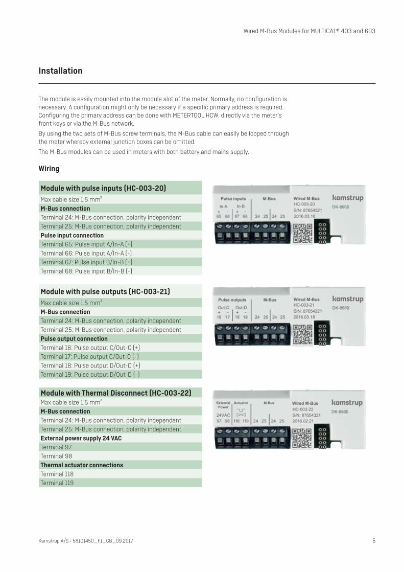
Module with pulse inputs (HC-003-20)Max cable size 1.5 mm²M-Bus connectionTerminal 24: M-Bus connection, polarity independentTerminal 25: M-Bus connection, polarity independentPulse input connectionTerminal 65: Pulse input A/In-A (+)Terminal 66: Pulse input A/In-A (-)Terminal 67: Pulse input B/In-B (+)Terminal 68: Pulse input B/In-B (-)
Module with pulse outputs (HC-003-21)Max cable size 1.5 mm²M-Bus connectionTerminal 24: M-Bus connection, polarity independentTerminal 25: M-Bus connection, polarity independentPulse output connectionTerminal 16: Pulse output C/Out-C (+)Terminal 17: Pulse output C/Out-C (-)Terminal 18: Pulse output D/Out-D (+)Terminal 19: Pulse output D/Out-D (-)
Module with Thermal Disconnect (HC-003-22)Max cable size 1.5 mm²M-Bus connectionTerminal 24: M-Bus connection, polarity independentTerminal 25: M-Bus connection, polarity independentExternal power supply 24 VACTerminal 97 Terminal 98Thermal actuator connectionsTerminal 118 Terminal 119

6 Kamstrup A/S • 58101450_F1_GB_09.2017
Wired M-Bus Modules for MULTICAL® 403 and 603or MULTICAL® 403
Communication
Communication is in accordance with the M-Bus standard EN 13757:2013.
Communication speedThe modules support 300, 2400, 9600 and 19200 baud communication speed and automati-cally detect the communication speed used by the M-Bus master.
Communication intervalIn order to maintain the full battery lifetime of the meter, the reading interval shall be >10 sec-onds. It is, however, recommended to use mains supply for very frequent reading applications.
As the modules do not have any form of communication limitations, they can be read out in second interval, but this will reduce the battery lifetime of the meter when the meter is battery-supplied.
The most frequent integration interval in MULTICAL® 403 is 4 seconds.
The most frequent integration interval in MULTICAL® 603 is 2 seconds.
A more frequent reading is not recommended as this will provide redundant information.
Communication via optical readout head Apart from the configurations in MULTICAL® itself, the primary M-Bus address can be config-ured via the optical readout head.
Communication from M-Bus master The following parameters can be configured with M-Bus commands via the connected M-Bus master:
• Primary address
• M-Bus ID number for secondary addressing
• Preset of the meter’s pulse inputs
• Meter clock synchronization
The M-Bus modules support download of new module software for implementing e.g. new functionality in already installed module, as well as for reconfiguring of the datagram. These functionalities are supported by the Kamstrup READy program platform.
7Kamstrup A/S • 58101450_F1_GB_09.2017
Wired M-Bus Modules for MULTICAL® 403 and 603
Communication
Pulse inputs The M-Bus module HC-003-20 is equipped with two pulse inputs, In-A and In-B, to collect and accumulate pulses remotely, e.g. from water meters and electricity meters. The pulse inputs are physically placed on the M-Bus module. However, the accumulation and data logging of values are made by the MULTICAL® calculator.
When installing the M-Bus module with pulse inputs in slot 2 of MULTICAL® 603, the pulse inputs will be registered in the meter as In-A2 and In-B2.
Pulse outputsThe M-Bus module HC-003-21 has two configurable pulse outputs, Out-C and Out-D, which are suitable for pulsing out selected registers from MULTICAL® 403 and 603. The pulse out-puts are physically placed on the M-Bus module, but the pulses are made by the MULTICAL® calculator.
Thermal DisconnectThe M-Bus module HC 003-22 is equipped with an output for connection of a 24 VAC Nor-mally Open or Normally Closed thermal actuator powered through the module’s power supply terminals. The Thermal Disconnect enables remote cutoff of the flow for e.g. energy saving, maintenance or as a result of leakage detection. The Thermal Disconnect system is physically placed on the M-Bus module. However, the control of the output is handled by MULTICAL® as a result of commands sent over the M-Bus network. For the remote control of the thermal actuators, the Windows-based PC program USB Meter Reader from Kamstrup is to be used.
Communication from M-Bus module A number of different datagrams are available when ordering meters. Further datagrams can be configured with METERTOOL HCW and READy.

8 Kamstrup A/S • 58101450_F1_GB_09.2017
Wired M-Bus Modules for MULTICAL® 403 and 603or MULTICAL® 403
Communication
Examples of available datagrams
Standard profile Tariff profile DACH profile Control profile
Heat energy E1
Cooling energy E3
Energy E8 (T1 x m³)
Energy E9 (T2 x m³)
Volume V1
Pulse input A
Pulse input B
Hour counter
Error hour counter
Temp. 1 Inlet
Temp. 2 Outlet
Differential temp.
Actual power
Max power this month
Actual flow
Max flow this month
Info
Date / time
Heat energy E1, Target
Cooling energy E3, Target
Energy E8 (T1 x m³), Target
Energy E9 (T2 x m³), Target
Volume V1, Target
Pulse input A, Target
Pulse input B, Target
Max power, Target
Max flow, Target
Target date
Meter type
Serial number
Module configuration
Module SW version
Heat energy E1
Cooling energy E3
Volume V1
Pulse input A
Pulse input B
Tariff 2
Tariff 3
Tariff 4
Hour counter
Error Hour Counter
Temp. 1 Inlet
Temp. 2 Outlet
Differential temp.
Actual power
Max power this month
Actual flow
Max flow this month
Info
Date / time
Heat energy E1, Target
Cooling energy E3, Target
Volume V1, Target
Pulse input A, Target
Pulse input B, Target
Tariff 2, Target
Tariff 3, Target
Tariff 4, Target
Max power, Target
Max flow, Target
Target date
Meter type
Serial number
Module configuration
Module SW version
Heat energy E1
Cooling energy E3
Heat with discount A1
Heat with surcharge A2
Volume V1
Pulse input A
Pulse input B
Tariff 2
Tariff 3
Tariff 4
Temp. 1 Inlet
Temp. 2 Outlet
Differential temp.
Temp. 5 Ref. Outlet
Actual power
Max power this month
Actual flow
Max flow this month
Info
Heat energy E1, Target
Cooling energy E3, Target
Pulse input A, Target
Pulse input B, Target
Heat with discount A1, Target
Heat with surcharge A2, Target
Tariff 2, Target
Tariff 3, Target
Tariff 4, Target
Max power, Target
Target date
Meter type
Serial number
Module configuration
Module SW version
Heat energy E1
Cooling energy E3
Volume V1
Temp. 1 Inlet
Temp. 2 Outlet
Differential temp.
Actual power
Actual flow
Info
Meter type
Serial number
Module configuration
Module SW version

9Kamstrup A/S • 58101450_F1_GB_09.2017
Wired M-Bus Modules for MULTICAL® 403 and 603
Loggers via M-Bus
Data from the meter’s historical loggers can be read out with M-Bus commands.
The following loggers are available for reading:
• Yearly logger
• Monthly logger
• Daily logger
• Minute loggers
The available registers depend on the meter configuration.
Reading the logger is very flexible, and both the number of logs as well as the log period can be selected.
Customer-specified datagrams
Dedicated datagrams can be specified in corporation with Kamstrup A/S. The datagram can be sent to already installed meters via METERTOOL HCW, connected to module via the con-nector on the module. Using READy, an update via the M-Bus network is also possible.
Module update
The module firmware as well as the module configuration can be updated with READy via the M-Bus master and directly through the connector on the module with METERTOOL HCW.

10 Kamstrup A/S • 58101450_F1_GB_09.2017
Wired M-Bus Modules for MULTICAL® 403 and 603or MULTICAL® 403
Technical specifications
Physical Only suitable for installation in MULTICAL® 403 and 603.
Galvanic isolated according to PTB-A50.1.
CommunicationProtocol M-Bus standard according to EN 13757:2013
Readout speed 300/2400/9600/19200 baud with automatically speed detection
Configuration METERTOOL HCW via module connector
READy via M-Bus master
SupplyPower supply Applicable in MULTICAL® 403 and 603 with battery and mains supply
Power consumption 1 unit load (1.5 mA) per M-Bus slave
Rin / Cin 422 Ω/0.5 nF
Max cable resistance 29 Ω/180 nF per pair
Operational temperature 5 - 55°C
Thermal DisconnectExternal power supply 24 VAC, e.g. Kamstrup safety transformer type no. 6699-403
Max output load 5W
Actuator reaction time < 5 minutes
The thermal or rotary actuator must be a 24 VAC, max 5W.
For thermal actuators with max 2.5 W consumption, the above safety transformer may be used for supplying both the MULTICAL® meter and the thermal actuator.
Notes
For Thermal Disconnect applications, MULTICAL® may not be battery-supplied.
The thermal actuator must be supplied by an external safety transformer.
Markings/approvals
EN 1434 in conjunction with the type approval of MULTICAL® 403 as well as of MULTICAL® 603.
EN 13757
CE approval

11Kamstrup A/S • 58101450_F1_GB_09.2017
Wired M-Bus Modules for MULTICAL® 403 and 603
Ordering
Description Order no.
M-Bus module with pulse inputs for MULTICAL® 403 and 603 HC-003-20
M-Bus module with pulse outputs for MULTICAL® 403 and 603 HC-003-21
M-Bus module with Thermal Disconnect for MULTICAL® 403 and 603 HC-003-22
M-Bus Master MultiPort 250D MBM-M210000
M-Bus Master MultiPort 250L MBM-M200000
USB configuration cable for H/C-modules 6699-035
Infrared optical readout head w/USB A plug 6699-099
Infrared optical readout head w/RS-232 D-SUB 9F 6699-102
Transformer 230/24 VAC 6699-403
METERTOOL HCW www.kamstrup.com
USB Meter Reader www.kamstrup.com
READy www.kamstrup.com

12 Kamstrup A/S • 58101450_F1_GB_09.2017
Wired M-Bus Modules for MULTICAL® 403 and 603or MULTICAL® 403
Available datagrams
XX YY ZZZ
Module typeWired M-Bus module + 2 pulse inputs 20Wired M-Bus module + 2 pulse outputs 21Wired M-Bus module + Thermal Disconnect 22
System configurationStandard 00 Suitable for MULTICAL®
Datagram 403 603Standard Profile Yearly Target Data 101 Standard Profile Monthly Target Data 102 Tariff Profile Yearly Target Data 103 Tariff Profile Monthly Target Data 104 DACH Profile Yearly Target Data 105 DACH Profile Monthly Target Data 106 Control Profile 107 CP Profile Yearly Target Data 108 … …Extended Pulse Input Profile Yearly Target Data 301 Extended Pulse Input Profile Monthly Target Data 302 Dual ULTRAFLOW Profile Yearly Target Data 303 Dual ULTRAFLOW Profile Monthly Target Data 304 Alternative Profile Yearly Target Data 305 Alternative Profile Monthly Target Data 306 PDO Profile Monthly Target Data 307 Energy Profile SNG 310 … …MULTICAL® 402/602 compatible data (402020/670020) Yearly Target Data 998 MULTICAL® III compatible data (6604/660S) Yearly Target Data 999
Not all registers are available in all meters. The cooling register E3, for example, will only be available in a meter configured as a cooling or combined heat/cooling meter. It will not be available in a heat meter.
For reading target registers, the wanted registers must be defined in the RR-configuration (logger contents).
Datagrams with the ZZZ values 301 to 399 are created for MULTICAL® 603. If they are used in MULTICAL® 403, some registers will not be available in the reading.
Kamstrup A/SIndustrivej 28, StillingDK-8660 SkanderborgT: +45 89 93 10 00F: +45 89 93 10 [email protected]
Kam
stru
p A
/S •
5810
1450
_F1_
GB_
09.2
017