Embed Size (px)
Citation preview

IntErnAtIOnAL EDItIOn 2009/2010
Control SystemtEChnICAL CAtALOGuE

Labelling your switches has never been easier with Dynamic Labelling Technology. Each scene title can be customised to suitthe new or existing C-Bus system. Featuring eight reprogrammable switches over two pages with an LCD backlit 64 x 128 pixel
screen, the new DLT switch range will help keep a home and building automation system organised.

Contents
TRADEMARKSClipsal is a registered trademark of Clipsal Australia Pty Ltd.C-Bus is a registered trademark of Clipsal Integrated Systems Pty Ltd.C-Gate is a registered trademark of Clipsal Integrated Systems Pty Ltd.Homegate is a registered trademark of Clipsal Integrated Systems Pty Ltd.Schedule Plus is a registered trademark of Clipsal Integrated Systems Pty Ltd.All other trademarks are the property of their respective owners.
InTRoDucTIon 2Introduction to Control Systems 2
c-BuSTEchnology 3Colour Options 4NEO Special Ordering Sheet 5Wireless Key Input Units 8Key Input Units 24System Units 35Input Units 42Output Units 61Multi Room Audio 83Software Packages 89
2
Introduction C-BusTechnology
3-90
TEchnIcAlInfoRMATIon 109C-Bus Wireless System Operation 110C-Bus Wireless Quick Start Guide 113C-Bus Design Guide 116C-Bus Learn Units 139 Quick Programming Guide
clIpSAlSEcuRITy 99Alarm Panels 100
ClipsalSecurity
TechnicalInformation
109-141
99-108occupAncySEnSoRS 91Ultrasonic Sensors 92Passive Infrared Sensors 95
OccupancySensors
91-98
InDEX 142Index by Catalogue Number 143Index by Product Description 145
Index
142-146
1

Introduction toControl SystemsTheavailabilityoflowcost,powerfulmicroprocessorsforbuildingandhomecontrolandmanagementsystemshascreatedunprecedentedcustomerexpectationsforincreasedcontrol,connectivityandintegrationofelectricalandlowvoltagesystems.Clipsal Integrated Systems, a business unit dedicated to supplying end-to-end building management, integrated control and intelligent wiring solutions, has the products, solutions and programs to help meet these expectations. Clipsal Integrated Systems provides complete end-to-end solutions, with products catering to any type or size of installation.
The flagship product of Clipsal Integrated Systems is C-Bus, a low cost network control system. C-Bus is an industry standard for applications such as power & energy management, lighting control and architectural dimming control, smart home applications, remote control, high power switching & demand shedding and is widely recognized as being one of the most feature rich and cost effective control system solutions in the world.
Clipsal Integrated Systems’ entry into the integrated control, monitoring and networking solutions market has been an outstanding success. Clipsal Integrated Systems has surpassed all expectations to become a major player in the thriving integrated control, monitoring and networking solutions industry.
With solutions ranging from power and lighting control, architectural dimming, energy management, security, home automation, residential cabling, electrical safety & software, Clipsal Integrated Systems can supply the systems expected for modern commercial buildings, hotels and homes.
Clipsal Integrated Systems provides high quality and comprehensive solutions to cater to all the requirements of both installers and end users alike. Clipsal Integrated Systems’ pursuit of solution excellence does not end with innovative products and leading edge solutions, but is demonstrated through our commitment to working closely with consultants, installers and customers to ensure a successful end result that complies with international standards. Clipsal Integrated Systems offer comprehensive training and accreditation programs to consultants and installers and our innovative product and warranty programs provide end users with complete peace of mind.
Clipsal Integrated Systems programs are active in over 25 different countries around the world, with local stocking, support, training and accreditation programs to ensure the highest standard of service at a local level, making Clipsal Integrated Systems truly “Your Global Partner in Control & Low Voltage Systems”.
2
C - B u s & E Z i n s t a l l Wi re l e s s Te c h n o l o g i e s
D y n a m i c La b e l l i n g Te c h n o l o gy ™
C - B u s Co l o u r To u c h S c re e n

C-BusTechnology

C-Bus TeChnology
Colour Options
standard Finish Plastic glass
Colour options White soft grey Desert Cream Brown Black Battleship White Cream Black Mid Brown electric sand grey
ordering Code We sg Ds CM BR BK gB gF 380 680 780
C-BusULTI - - - - - - - ✔ ✔ ✔ ✔
WirelessULTI - - - - - - - ✔ ✔ ✔ ✔
C-BusNEO ✔ ✔ ✔ ✔ ✔ ✔ ✔ - - - - WirelessNEO ✔ ✔ ✔ ✔ ✔ ✔ ✔ - - - - 2000Series ✔ ✔ ✔ ✔ ✔ ✔ - - - - - C2000Classic ✔ ✔ ✔ ✔ ✔ ✔ - - - - - SC2000Slimline ✔ ✔ ✔ ✔ ✔ ✔ - - - - - E2000Series ✔ ✔ ✔ ✔ ✔ ✔ - - - - -
C-graphics Finish Colour options Mahogany Bird’s eye Red Ajax Alpine Brazillian Dancing Purple Checkers sun gold silver Mirror gun Metal Wood Wood Mahogany White Black Black Rain Dream electroplated electroplated electroplated Wood Marble Marble Marble
ordering Code MW BW RW WM gM BM DA PA CA ge se ue
C2000Classic ✔ ✔ ✔ ✔ ✔ ✔ ✔ ✔ ✔ ✔ ✔ ✔
E2000British ✔ ✔ ✔ ✔ ✔ ✔ ✔ ✔ ✔ ✔ ✔ ✔
C-spectra Finish Colour options Black White smoke Red green Blue Red green Blue Champagne gold silver
ordering Code BK We sC5 sC1 sC1 sC1 sP1 sP1 sP1 sD1 sD1 sD1
E2000British ✔ ✔ ✔ ✔ ✔ ✔ ✔ ✔ ✔ ✔ ✔ ✔
Metal Finish Colour options Brushed Brushed Chrome gold gun Metal stainless Polished stainless Polished Polished Polished Powder Aluminium Brass Metal steel Brass steel Brass stainless Brass Coated Clip-on Clip-on screw-on screw-on steel grey
ordering Code BA BB Ch gD gM ss Bs W,ss W,Bs s B gy
C2000Classic ✔ ✔ ✔ ✔ ✔ ✔ ✔ ✔ ✔ - - - SC2000Slimline ✔ ✔ ✔ ✔ ✔ ✔ ✔ ✔ ✔ - - - SL2000Eclipse ✔ ✔ ✔ ✔ ✔ ✔ ✔ ✔ ✔ - - - ESMRange - - - - - - - - - - - ✔
ReflectionSeries - - - - - - - - - ✔ - - MetalPlateSeries - - - - - - - - - ✔ ✔ -
C-Bus Technology
�

�
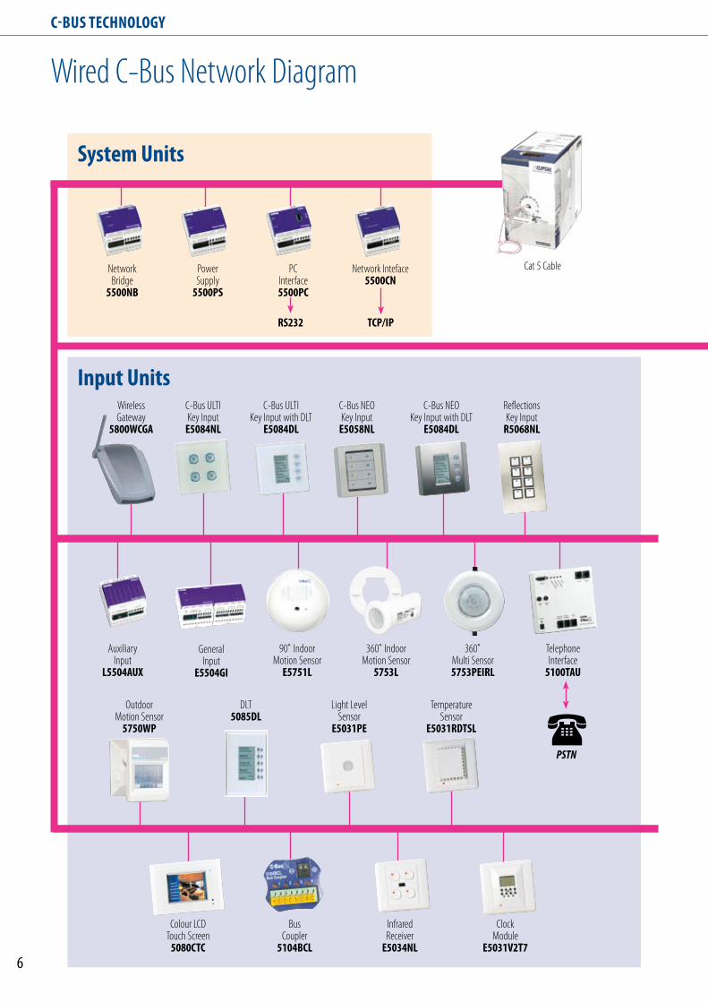
Wired C-Bus Network Diagram
C-Bus TeChnology
system units
Input unitsC-Bus ULTI
Key Input with DLTe5084Dl
C-Bus NEO Key Input
e5058nl
ReflectionsKey Input
R5068nl
AuxiliaryInput
l5504AuX
OutdoorMotion Sensor
5750WP
BusCoupler
5104BCl
ClockModule
e5031V2T7
InfraredReceiver
e5034nl
Light LevelSensor
e5031Pe
TelephoneInterface
5100TAu
PSTN
DLT5085Dl
TemperatureSensor
e5031RDTsl
PC Interface5500PC
Rs232
Network Inteface 5500Cn
TCP/IP
Network Bridge
5500nB
360˚ Multi Sensor5753PeIRl
Power Supply
5500Ps
90˚ Indoor Motion Sensor
e5751l
GeneralInput
e5504gI
360˚ Indoor Motion Sensor
5753l
Colour LCD Touch Screen
5080CTC
WirelessGateway
5800WCgA
C-Bus ULTI Key Input
e5084nl
Cat 5 Cable
�
C-Bus NEO Key Input with DLT
e5084Dl

software
output units
Infrared Output5034nIRT
10A, 12A, 16A & 20A12 Channel High
Powered Dimmersl5512D10B2
Schedule PlusVersion 4
6 Channel Pre SeriesDimmer
l5106D10lP
2 ChannelDALI Output5502DAl
8 ChannelDSI Outputl5508DsI
4 ChannelAnalogue Output
l5504AMP
C-Bus Toolkit Software
C-Bus TeChnology
�
Wired C-Bus Network Diagram
Interfaces
MinderPRo Automation
Controller
CrestronController
serialInterface
AMX Controller
TCP/IPInterface
Multi Room AudioAudio Matrix Switcher
5560884Audio Amplifier
560125DAudio Amplifier
56011oRAudio Speakers, Circular
5600ICPAudio Speakers, Square
5600IWP
4, 8, 12 Channel Relayl5512RVF
4 Channel Change Over Relayl5504RVFC
4 Channel Relay Driver5504RDP
2, 8 Channel Dimmersl5504D2A
HomeGateVersion 4
C-Bus TeChnology | WIRELESS KEy INPUT UNITS
8
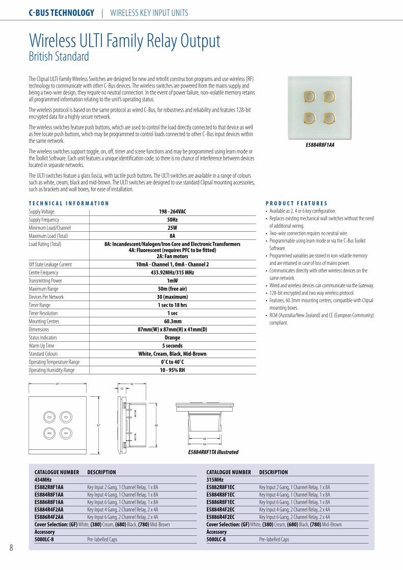
Wireless ULTI Family Relay OutputBritish Standard
The Clipsal ULTI Family Wireless Switches are designed for new and retrofit construction programs and use wireless (RF) technology to communicate with other C-Bus devices. The wireless switches are powered from the mains supply and being a two-wire design, they require no neutral connection. In the event of power failure, non-volatile memory retains all programmed information relating to the unit’s operating status.
The wireless protocol is based on the same protocol as wired C-Bus, for robustness and reliability and features 128-bit encrypted data for a highly secure network.
The wireless switches feature push buttons, which are used to control the load directly connected to that device as well as free locate push buttons, which may be programmed to control loads connected to other C-Bus input devices within the same network.
The wireless switches support toggle, on, off, timer and scene functions and may be programmed using learn mode or the Toolkit Software. Each unit features a unique identification code, so there is no chance of interference between devices located in separate networks.
The ULTI switches feature a glass fascia, with tactile push buttons. The ULTI switches are available in a range of colours such as white, cream, black and mid-brown. The ULTI switches are designed to use standard Clipsal mounting accessories, such as brackets and wall boxes, for ease of installation.
T e C h n I C A l I n F o R M A T I o n Supply Voltage 198 - 264VACSupply Frequency 50hz Minimum Load/Channel 25W Maximum Load (Total) 8A Load Rating (Total) 8A: Incandescent/halogen/Iron Core and electronic Transformers 4A: Fluorescent (requires PFC to be fitted) 2A: Fan motors Off State Leakage Current 10mA - Channel 1, 0mA - Channel 2 Centre Frequency 433.92Mhz/315 MhzTransmitting Power 1mW Maximum Range 50m (free air) Devices Per Network 30 (maximum) Timer Range 1 sec to 18 hrs Timer Resolution 1 sec Mounting Centres 60.3mm Dimensions 87mm(W) x 87mm(h) x 41mm(D) Status Indicators orange Warm Up Time 5 seconds Standard Colours White, Cream, Black, Mid-Brown Operating Temperature Range 0˚C to 40˚C Operating Humidity Range 10 - 95% Rh
P R o D u C T F e A T u R e s • Available as 2, 4 or 6 key configuration. • Replaces existing mechanical wall switches without the need of additional wiring. • Two-wire connection requires no neutral wire. • Programmable using learn mode or via the C-Bus Toolkit Software. • Programmed variables are stored in non-volatile memory and are retained in case of loss of mains power. • Communicates directly with other wireless devices on the same network. • Wired and wireless devices can communicate via the Gateway. • 128-bit encrypted and two way wireless protocol. • Features, 60.3mm mounting centres, compatible with Clipsal mounting boxes. • RCM (Australia/New Zealand) and CE (European Community) compliant.
CATAlogue nuMBeR DesCRIPTIon434Mhz e5882R8F1AA Key Input 2 Gang, 1 Channel Relay, 1 x 8A e5884R8F1AA Key Input 4 Gang, 1 Channel Relay, 1 x 8A e5886R8F1AA Key Input 6 Gang, 1 Channel Relay, 1 x 8A e5884R4F2AA Key Input 4 Gang, 2 Channel Relay, 2 x 4A e5886R4F2AA Key Input 6 Gang, 2 Channel Relay, 2 x 4ACover selection: (gF) White, (380) Cream, (680) Black, (780) Mid-BrownAccessory5080lC-8 Pre-labelled Caps
CATAlogue nuMBeR DesCRIPTIon315Mhz e5882R8F1eC Key Input 2 Gang, 1 Channel Relay, 1 x 8A e5884R8F1eC Key Input 4 Gang, 1 Channel Relay, 1 x 8A e5886R8F1eC Key Input 6 Gang, 1 Channel Relay, 1 x 8A e5884R4F2eC Key Input 4 Gang, 2 Channel Relay, 2 x 4A e5886R4F2eC Key Input 6 Gang, 2 Channel Relay, 2 x 4ACover selection: (gF) White, (380) Cream, (680) Black, (780) Mid-BrownAccessory5080lC-8 Pre-labelled Caps
87 66
87
12
42
50
46
87 66
87
12
42
50
46
E5884R8F1TA illustrated
E5884R8F1AA

C-Bus TeChnology | WIRELESS KEy INPUT UNITS
9
Wireless ULTI Family Relay OutputAustralian/US Standard
The Clipsal ULTI Family Wireless Switches are designed for new and retrofit construction programs and use wireless (RF) technology to communicate with other C-Bus devices. The wireless switches are powered from the mains supply and being a two-wire design, they require no neutral connection. In the event of power failure, non-volatile memory retains all programmed information relating to the unit’s operating status.
The wireless protocol is based on the same protocol as wired C-Bus, for robustness and reliability and features 128-bit encrypted data for a highly secure network.
The wireless switches feature push buttons, which are used to control the load directly connected to that device as well as free locate push buttons, which may be programmed to control loads connected to other C-Bus input devices within the same network.
The wireless switches support toggle, on, off, timer and scene functions and may be programmed using learn mode or the Toolkit Software. Each unit features a unique identification code, so there is no chance of interference between devices located in separate networks.
The ULTI switches feature a glass fascia, with tactile push buttons. The ULTI switches are available in a range of colours such as white, cream, black and mid-brown. The ULTI switches are designed to use standard Clipsal mounting accessories, such as brackets and wall boxes, for ease of installation.
T e C h n I C A l I n F o R M A T I o n Supply Voltage 198 - 264VACSupply Frequency 50hz Minimum Load/Channel 25W Maximum Load (Total) 8A Load Rating (Total) 8A: Incandescent/halogen/Iron Core and electronic Transformers 4A: Fluorescent (requires PFC to be fitted) 2A: Fan motors Off State Leakage Current 10mA - Channel 1, 0mA - Channel 2 Centre Frequency 433.92MhzTransmitting Power 1mW Maximum Range 50m (free air) Devices Per Network 30 (maximum) Timer Range 1 sec to 18 hrs Timer Resolution 1 sec Mounting Centres 84mm Dimensions 116mm(W) x 76mm(h) x 41mm(D) Status Indicators orange Warm Up Time 5 seconds Standard Colours White, Cream, Black, Mid-Brown Operating Temperature Range 0˚C to 40˚C Operating Humidity Range 10 - 95% Rh
P R o D u C T F e A T u R e s • Available as 2, 4 or 6 key configuration. • Replaces existing mechanical wall switches without the need of additional wiring. • Two-wire connection requires no neutral wire. • Programmable using learn mode or via the C-Bus Toolkit Software. • Programmed variables are stored in non-volatile memory and are retained in case of loss of mains power. • Communicates directly with other wireless devices on the same network. • Wired and wireless devices can communicate via the Gateway. • 128-bit encrypted and two way wireless protocol. • Features, 84mm mounting centres, compatible with Clipsal mounting boxes. • RCM (Australia/New Zealand) and CE (European Community) compliant.
5884R8F1AA
CATAlogue nuMBeR DesCRIPTIon 5882R8F1AA Key Input 2 Gang, 1 Channel Relay, 1 x 8A5884R8F1AA Key Input 4 Gang, 1 Channel Relay, 1 x 8A5886R8F1AA Key Input 6 Gang, 1 Channel Relay, 1 x 8A5884R4F2AA Key Input 4 Gang, 2 Channel Relay, 2 x 4A5886R4F2AA Key Input 6 Gang, 2 Channel Relay, 2 x 4ACover selection: (gF) White, (380) Cream, (680) Black, (780) Mid-Brown
CATAlogue nuMBeR DesCRIPTIon Accessories5080sD Spacers to Suit ULTI Australian/US Standard Switches5080lC-8 Pre-labelled Caps
116
76
12
42
50
46
66
116
76
12
42
50
46
66
5884R8F1AA illustrated

C-Bus TeChnology | WIRELESS KEy INPUT UNITS
10
Wireless ULTI Family Leading Edge DimmersBritish Standard
The Clipsal ULTI Family Wireless Leading Edge Dimmers are designed for new and retrofit construction programs and use wireless (RF) technology to communicate with other C-Bus devices. The wireless switches are powered from the mains supply and being a two-wire design, they require no neutral connection. In the event of power failure, non-volatile memory retains all programmed information relating to the unit’s operating status.
The wireless protocol is based on the same protocol as wired C-Bus, for robustness and reliability and features 128-bit encrypted data for a highly secure network. The wireless switches feature push buttons, which are used to control the load directly connected to that device as well as free locate push buttons, which may be programmed to control loads connected to other C-Bus input devices within the same network.
The leading edge dimmers are compatible with incandescent, iron core, inductive input electronic transformers and fan motor loads.The wireless switches support dimmer, toggle, on, off, timer and scene functions and may be programmed using learn mode or the Toolkit Software. Each unit features a unique identification code, so there is no chance of interference between devices located in separate networks.
The ULTI switches feature a glass fascia, with tactile push buttons. The ULTI switches are available in a range of colours such as white, cream, black and mid-brown. The ULTI switches are designed to use standard Clipsal mounting accessories, such as brackets and wall boxes, for ease of installation.
T e C h n I C A l I n F o R M A T I o n Supply Voltage 198 - 264VACSupply Frequency 50hz Minimum Load/Channel 25W lamp or 0.25A fan motor Maximum Load (Total) 500W, 2A (single channel unit) 250W, 1A (two channel unit) Load Rating (Total) 2A Off State Leakage Current 12mA - Channel 1, 5mA - Channel 2 Centre Frequency 433.92Mhz/315MhzTransmitting Power 1mW Maximum Range 50m (free air) Devices Per Network 30 (maximum) Timer Range 1 sec to 18 hrs Timer Resolution 1 sec Mounting Centres 60.3mm Dimensions 87mm(W) x 87mm(h) x 41mm(D) Status Indicators orange Warm Up Time 5 seconds Standard Colours White, Cream, Black, Mid-BrownOperating Temperature Range 0˚C to 40˚C Operating Humidity Range 10 - 95% Rh
P R o D u C T F e A T u R e s • Available as 2, 4 or 6 key configuration. • Replaces existing mechanical wall switches without the need of additional wiring. • Two-wire connection requires no neutral wire. • Programmable using learn mode or via the C-Bus Toolkit Software. • Programmed variables are stored in non-volatile memory and are retained in case of loss of mains power. • Communicates directly with other wireless devices on the same network. • Wired and wireless devices can communicate via the Gateway. • 128-bit encrypted and two way wireless protocol. • Features, 60.3mm mounting centres, compatible with Clipsal mounting boxes. • RCM (Australia/New Zealand) and CE (European Community) compliant.
E5884D2L1AA
87 66
87
12
42
50
46
87 66
87
12
42
50
46
E5884D2L1TA illustrated
CATAlogue nuMBeR DesCRIPTIon434Mhz e5882D2l1AA Key Input 2 Gang, 1 Channel Relay, 1 x 8A e5884D2l1AA Key Input 4 Gang, 1 Channel Relay, 1 x 8A e5886D2l1AA Key Input 6 Gang, 1 Channel Relay, 1 x 8A e5884D1l2AA Key Input 4 Gang, 2 Channel Relay, 2 x 4A e5886D1l2AA Key Input 6 Gang, 2 Channel Relay, 2 x 4ACover selection: (gF) White, (380) Cream, (680) Black, (780) Mid-BrownAccessory5080lC-8 Pre-labelled Caps
CATAlogue nuMBeR DesCRIPTIon315Mhz e5882D2l1eC Key Input 2 Gang, 1 Channel Relay, 1 x 8A e5884D2l1eC Key Input 4 Gang, 1 Channel Relay, 1 x 8A e5886D2l1eC Key Input 6 Gang, 1 Channel Relay, 1 x 8A e5884D1l2eC Key Input 4 Gang, 2 Channel Relay, 2 x 4A e5886D1l2eC Key Input 6 Gang, 2 Channel Relay, 2 x 4ACover selection: (gF) White, (380) Cream, (680) Black, (780) Mid-BrownAccessory5080lC-8 Pre-labelled Caps

C-Bus TeChnology | WIRELESS KEy INPUT UNITS
11
Wireless ULTI Family Leading Edge DimmersAustralian/US Standard
The Clipsal ULTI Family Wireless Leading Edge Dimmers are designed for new and retrofit construction programs and use wireless (RF) technology to communicate with other C-Bus devices. The wireless switches are powered from the mains supply and being a two-wire design, they require no neutral connection. In the event of power failure, non-volatile memory retains all programmed information relating to the unit’s operating status.
The wireless protocol is based on the same protocol as wired C-Bus, for robustness and reliability and features 128-bit encrypted data for a highly secure network. The wireless switches feature push buttons, which are used to control the load directly connected to that device as well as free locate push buttons, which may be programmed to control loads connected to other C-Bus input devices within the same network.
The leading edge dimmers are compatible with incandescent, iron core transformers, inductive input electronic transformers and fan motor loads. The wireless switches support dimmer, toggle, on, off, timer and scene functions and may be programmed using learn mode or the Toolkit Software. Each unit features a unique identification code, so there is no chance of interference between devices located in separate networks.
The ULTI switches feature a glass fascia, with tactile push buttons. The ULTI switches are available in a range of colours such as white, cream, black and mid-brown. The ULTI switches are designed to use standard Clipsal mounting accessories, such as brackets and wall boxes, for ease of installation.
T e C h n I C A l I n F o R M A T I o n Supply Voltage 216 - 264VACSupply Frequency 50hz Minimum Load/Channel 25W lamp or 0.25A fan motor Maximum Load (Total) 500W, 2A (single channel unit) 250W, 1A (two channel unit) Load Rating (Total) 2A Off State Leakage Current 10mA - Channel 1, 5mA - Channel 2 Centre Frequency 433.92MhzTransmitting Power 1mW Maximum Range 50m (free air) Devices Per Network 30 (maximum) Timer Range 1 sec to 18 hrs Timer Resolution 1 sec Mounting Centres 84mm Dimensions 116mm(W) x 76mm(h) x 41mm(D) Status Indicators orange Warm Up Time 5 seconds Standard Colours White, Cream, Black, Mid-BrownOperating Temperature Range 0˚C to 40˚C Operating Humidity Range 10 - 95% Rh
P R o D u C T F e A T u R e s • Available as 2, 4 or 6 key configuration. • Replaces existing mechanical wall switches without the need of additional wiring. • Two-wire connection requires no neutral wire. • Programmable using learn mode or via the C-Bus Toolkit Software. • Programmed variables are stored in non-volatile memory and are retained in case of loss of mains power. • Communicates directly with other wireless devices on the same network. • Wired and wireless devices can communicate via the Gateway. • 128-bit encrypted and two way wireless protocol. • Features, 84mm mounting centres, compatible with Clipsal mounting boxes. • RCM (Australia/New Zealand) and CE (European Community) compliant.
CATAlogue nuMBeR DesCRIPTIon 5882D2l1AA Key Input 2 Gang, 1 Channel Leading Edge Dimmer, 1 x 2A5884D2l1AA Key Input 4 Gang, 1 Channel Leading Edge Dimmer, 1 x 2A5886D2l1AA Key Input 6 Gang, 1 Channel Leading Edge Dimmer, 1 x 2A5884D1l2AA Key Input 4 Gang, 2 Channel Leading Edge Dimmer, 2 x 1A5886D1l2AA Key Input 6 Gang, 2 Channel Leading Edge Dimmer, 2 x 1ACover selection: (gF) White, (380) Cream, (680) Black, (780) Mid-Brown
CATAlogue nuMBeR DesCRIPTIon Accessories5080sD Spacers to Suit ULTI Australian/US Standard Switches5080lC-8 Pre-labelled Caps
5884D2L1AA
116
76
12
42
50
46
66
116
76
12
42
50
46
66
5884D2L1AA illustrated

C-Bus TeChnology | WIRELESS KEy INPUT UNITS
12
Wireless ULTI Family Trailing Edge DimmersBritish Standard
The Clipsal ULTI Family Wireless Trailing Edge are designed for new and retrofit construction programs and use wireless (RF) technology to communicate with other C-Bus devices. The wireless switches are powered from the mains supply and being of a two-wire design, they require no neutral connection. In the event of power failure, non-volatile memory retains all programmed information relating to the unit’s operating status.
The wireless protocol is based on the same protocol as wired C-Bus, for robustness and reliability and features 128-bit encrypted data for a highly secure network. The wireless switches feature push buttons, which are used to control the load directly connected to that device as well as free locate push buttons, which may be programmed to control loads connected to other C-Bus input devices within the same network.
The trailing edge dimmers are compatible with incandescent and capacitive input electronic transformers loads. The wireless switches support dimmer, toggle, on, off, timer and scene functions and may be programmed using learn mode or the Toolkit Software. Each unit features a unique identification code, so there is no chance of interference between devices located in separate networks.
The ULTI switches feature a glass fascia, with tactile push buttons. The ULTI switches are available in a range of colours such as white, cream, black and mid-brown. The ULTI switches are designed to use standard Clipsal mounting accessories, such as brackets and wall boxes, for ease of installation.
T e C h n I C A l I n F o R M A T I o n Supply Voltage 216 - 264VAC Supply Frequency 50hz Minimum Load/Channel 25W lamp Maximum Load (Total) 500W, 2A (single channel unit) 250W, 1A (two channel unit) Load Rating (Total) 2A Off State Leakage Current 15mA - Channel 1, 10mA - Channel 2 Centre Frequency 433.92Mhz/315MhzTransmitting Power 1mW Maximum Range 50m (free air) Devices Per Network 30 (maximum) Timer Range 1 sec to 18 hrs Timer Resolution 1 sec Mounting Centres 60.3mm Dimensions 87mm(W) x 87mm(h) x 41mm(D) Status Indicators orange Warm Up Time 5 seconds Standard Colours White, Cream , Black, Mid-BrownOperating Temperature Range 0˚C to 40˚C Operating Humidity Range 10 - 95% Rh
P R o D u C T F e A T u R e s • Available as 2, 4 or 6 key configuration. • Replaces existing mechanical wall switches without the need of additional wiring. • Two-wire connection requires no neutral wire. • Programmable using learn mode or via the C-Bus Toolkit Software. • Programmed variables are stored in non-volatile memory and are retained in case of loss of mains power. • Communicates directly with other wireless devices on the same network. • Wired and wireless devices can communicate via the Gateway. • 128-bit encrypted and two way wireless protocol. • Features, 60.3mm mounting centres, compatible with Clipsal mounting boxes. • RCM (Australia/New Zealand) and CE (European Community) compliant.
E5884D2T1AA
87 66
87
12
42
50
46
87 66
87
12
42
50
46
E5884D2T1TA illustrated
CATAlogue nuMBeR DesCRIPTIon434Mhze5882D2T1AA Key Input 2 Gang, 1 Channel Trailing Edge Dimmer, 1 x 2Ae5884D2T1AA Key Input 4 Gang, 1 Channel Trailing Edge Dimmer, 1 x 2Ae5886D2T1AA Key Input 6 Gang, 1 Channel Trailing Edge Dimmer, 1 x 2Ae5884D1T2AA Key Input 4 Gang, 2 Channel Trailing Edge Dimmer, 2 x 1Ae5886D1T2AA Key Input 6 Gang, 2 Channel Trailing Edge Dimmer, 2 x 1ACover selection: (gF) White, (380) Cream, (680) Black, (780) Mid-BrownAccessory5080lC-8 Pre-labelled Caps
CATAlogue nuMBeR DesCRIPTIon315Mhz e5882D2T1eC Key Input 2 Gang, 1 Channel Trailing Edge Dimmer, 1 x 2Ae5884D2T1eC Key Input 4 Gang, 1 Channel Trailing Edge Dimmer, 1 x 2Ae5886D2T1eC Key Input 6 Gang, 1 Channel Trailing Edge Dimmer, 1 x 2Ae5884D1T2eC Key Input 4 Gang, 2 Channel Trailing Edge Dimmer, 2 x 1Ae5886D1T2eC Key Input 6 Gang, 2 Channel Trailing Edge Dimmer, 2 x 1ACover selection: (gF) White, (380) Cream, (680) Black, (780) Mid-BrownAccessory5080lC-8 Pre-labelled Caps

C-Bus TeChnology | WIRELESS KEy INPUT UNITS
13
Wireless ULTI Family Trailing Edge DimmersAustralian/US Standard
The Clipsal ULTI Family Wireless Trailing Edge Dimmers are designed for new and retrofit construction programs and use wireless (RF) technology to communicate with other C-Bus devices. The wireless switches are powered from the mains supply and being of a two-wire design, they require no neutral connection. In the event of power failure, non-volatile memory retains all programmed information relating to the unit’s operating status.
The wireless protocol is based on the same protocol as wired C-Bus, for robustness and reliability and features 128-bit encrypted data for a highly secure network. The wireless switches feature push buttons, which are used to control the load directly connected to that device as well as free locate push buttons, which may be programmed to control loads connected to other C-Bus input devices within the same network.
The trailing edge dimmers are compatible with incandescent and capacitive input electronic transformers loads. The wireless switches support dimmer, toggle, on, off, timer and scene functions and may be programmed using learn mode or the Toolkit Software. Each unit features a unique identification code, so there is no chance of interference between devices located in separate networks.
The ULTI switches feature a glass fascia, with tactile push buttons. The ULTI switches are available in a range of colours such as white, cream, black and mid-brown. The ULTI switches are designed to use standard Clipsal mounting accessories, such as brackets and wall boxes, for ease of installation.
T e C h n I C A l I n F o R M A T I o n Supply Voltage 216 - 264VACSupply Frequency 50hz Minimum Load/Channel 25W lamp Maximum Load (Total) 500W, 2A (single channel unit) 250W, 1A (two channel unit) Load Rating (Total) 2A Off State Leakage Current 15mA - Channel 1, 10mA - Channel 2 Centre Frequency 433.92MhzTransmitting Power 1mW Maximum Range 50m (free air) Devices Per Network 30 (maximum) Timer Range 1 sec to 18 hrs Timer Resolution 1 sec Mounting Centres 84mm Dimensions 116mm(W) x 76mm(h) x 41mm(D) Status Indicators orange Warm Up Time 5 seconds Standard Colours White, Cream, Black, Mid-BrownOperating Temperature Range 0˚C to 40˚C Operating Humidity Range 10 - 95% Rh
P R o D u C T F e A T u R e s • Available as 2, 4 or 6 key configuration. • Replaces existing mechanical wall switches without the need of additional wiring. • Two-wire connection requires no neutral wire. • Programmable using learn mode or via the C-Bus Toolkit Software. • Programmed variables are stored in non-volatile memory and are retained in case of loss of mains power. • Communicates directly with other wireless devices on the same network. • Wired and wireless devices can communicate via the Gateway. • 128-bit encrypted and two way wireless protocol. • Features, 84mm mounting centres, compatible with Clipsal mounting boxes. • RCM (Australia/New Zealand) and CE (European Community) compliant.
CATAlogue nuMBeR DesCRIPTIon 5882D2T1AA Key Input 2 Gang, 1 Channel Trailing Edge Dimmer, 1 x 2A5884D2T1AA Key Input 4 Gang, 1 Channel Trailing Edge Dimmer, 1 x 2A5886D2T1AA Key Input 6 Gang, 1 Channel Trailing Edge Dimmer, 1 x 2A5884D1T2AA Key Input 4 Gang, 2 Channel Trailing Edge Dimmer, 2 x 1A5886D1T2AA Key Input 6 Gang, 2 Channel Trailing Edge Dimmer, 2 x 1ACover selection: (gF) White, (380) Cream, (680) Black, (780) Mid-Brown
CATAlogue nuMBeR DesCRIPTIon Accessories5080sD Spacers to Suit ULTI Australian/US Standard Switches5080lC-8 Pre-labelled Caps
5884D2T1AA
116
76
12
42
50
46
66
116
76
12
42
50
46
66
5884D2T1AA illustrated

C-Bus TeChnology | WIRELESS KEy INPUT UNITS
14
Wireless NEO Family Relay OuputBritish Standard
The Clipsal NEO Family Wireless Switches are designed for new and retrofit construction programs and use wireless (RF) technology to communicate with other C-Bus devices. The wireless switches are powered from the mains supply and being of a two-wire design, they require no neutral connection. In the event of power failure, non-volatile memory retains all programmed information relating to the unit’s operating status.
The wireless protocol is based on the same protocol as wired C-Bus, for robustness and reliability and features 128-bit encrypted data for a highly secure network. The wireless switches feature push buttons, which are used to control the load directly connected to that device as well as free locate push buttons, which may be programmed to control loads connected to other C-Bus devices within the same network.
The wireless switches support toggle, on, off, timer and scene functions and may be programmed using learn mode or the Toolkit Software. Each unit features a unique identification code, so there is no chance of interference between devices located in separate networks.
The NEO switches are designed to use standard Clipsal mounting accessories, such as brackets and wall boxes, for ease of installation.
T e C h n I C A l I n F o R M A T I o n Supply Voltage 198 - 264VAC Supply Frequency 50hz Minimum Load/Channel 25W Maximum Load (Total) 8A Load Rating (Total) 8A: Incandescent/halogen/Iron Core and electronic Transformers 4A: Fluorescent (requires PFC to be fitted) 2A: Fan motors Off State Leakage Current 10mA - Channel 1, 0mA - Channel 2 Centre Frequency 433.92Mhz/315MhzTransmitting Power 1mW Maximum Range 50m (free air) Devices Per Network 30 (maximum) Timer Range 1 sec to 18 hrs Timer Resolution 1 sec Mounting Centres 60.3mm Dimensions 87mm(W) x 87mm(h) x 41mm(D) Status Indicators orangeWarm Up Time 5 seconds Standard Colours We, sg, Ds, CM, BR, BK and gB Operating Temperature Range 0˚C to 40˚C Operating Humidity Range 10 - 95% Rh
P R o D u C T F e A T u R e s • Available as 2, 4 or 8 key configuration. • Replaces existing mechanical wall switches without the need of additional wiring. • Two-wire connection requires no neutral wire. • Programmable using learn mode or via the C-Bus Toolkit Software. • Programmed variables are stored in non-volatile memory and are retained in case of loss of mains power. • Communicates directly with other wireless devices on the same network. • Wired and wireless devices can communicate via the Gateway. • 128-bit encrypted and two-way wireless protocol. • Features, 60.3mm mounting centres, compatible with Clipsal mounting boxes. • RCM (Australia/New Zealand) and CE (European Community) compliant.
CATAlogue nuMBeR DesCRIPTIon 434Mhz e5852R8F1AA Key Input 2 Gang, 1 Channel Relay, 1 x 8Ae5854R8F1AA Key Input 4 Gang, 1 Channel Relay, 1 x 8Ae5858R8F1AA Key Input 8 Gang, 1 Channel Relay, 1 x 8Ae5854R4F2AA Key Input 4 Gang, 2 Channel Relay, 2 x 4Ae5858R4F2AA Key Input 8 Gang, 2 Channel Relay, 2 x 4A
CATAlogue nuMBeR DesCRIPTIon 315Mhz e5852R8F1eC Key Input 2 Gang, 1 Channel Relay, 1 x 8Ae5854R8F1eC Key Input 4 Gang, 1 Channel Relay, 1 x 8Ae5858R8F1eC Key Input 8 Gang, 1 Channel Relay, 1 x 8Ae5854R4F2eC Key Input 4 Gang, 2 Channel Relay, 2 x 4Ae5858R4F2eC Key Input 8 Gang, 2 Channel Relay, 2 x 4A
E5858R8F1AA
Cover selection: (We) White Electric, (sg) Soft Grey, (Ds) Desert Sand, (CM) Cream, (BR) Brown, (BK) Black, (gB) Battleship Grey
87 sq. 37
66
50
46
87 sq. 37
66
50
46
E5854R8F1TA illustrated

C-Bus TeChnology | WIRELESS KEy INPUT UNITS
15
Wireless NEO Family Relay OuputAustralian/US Standard
The Clipsal NEO Family Wireless Switches are designed for new and retrofit construction programs and use wireless (RF) technology to communicate with other C-Bus devices. The wireless switches are powered from the mains supply and being of a two-wire design, they require no neutral connection. In the event of power failure, non-volatile memory retains all programmed information relating to the unit’s operating status.
The wireless protocol is based on the same protocol as wired C-Bus, for robustness and reliability and features 128-bit encrypted data for a highly secure network. The wireless switches feature push buttons, which are used to control the load directly connected to that device as well as free locate push buttons, which may be programmed to control loads connected to other C-Bus input devices within the same network.
The wireless switches support toggle, on, off, timer and scene functions and may be programmed using learn mode or the Toolkit Software. Each unit features a unique identification code, so there is no chance of interference between devices located in separate networks.
The NEO switches are designed to use standard Clipsal mounting accessories, such as brackets and wall boxes, for ease of installation.
T e C h n I C A l I n F o R M A T I o n Supply Voltage 198 - 264VAC Supply Frequency 50hz Minimum Load/Channel 25W Maximum Load (Total) 8A Load Rating (Total) 8A: Incandescent/halogen/Iron Core and electronic Transformers 4A: Fluorescent (requires PFC to be fitted) 2A: Fan motors Off State Leakage Current 10mA - Channel 1, 0mA - Channel 2 Centre Frequency 433.92Mhz Transmitting Power 1mW Maximum Range 50m (free air) Devices Per Network 30 (maximum) Timer Range 1 sec to 18 hrs Timer Resolution 1 sec Mounting Centres 84mm Dimensions 116mm(W) x 76mm(h) x 41mm(D) Status Indicators orange Warm Up Time 5 seconds Standard Colours We, sg, Ds, CM, BR, BK and gB Operating Temperature Range 0˚C to 40˚C Operating Humidity Range 10 - 95% Rh
P R o D u C T F e A T u R e s • Available as 2, 4 or 8 key configuration. • Replaces existing mechanical wall switches without the need of additional wiring. • Two-wire connection requires no neutral wire. • Programmable using learn mode or via the C-Bus Toolkit Software. • Programmed variables are stored in non-volatile memory and are retained in case of loss of mains power. • Communicates directly with other wireless devices on the same network. • Wired and wireless devices can communicate via the Gateway. • 128-bit encrypted and two-way wireless protocol. • Features, 84mm mounting centres, compatible with Clipsal mounting boxes. • RCM (Australia/New Zealand) and CE (European Community) compliant.
5858R8F1AA
66
50
116
3776
46
66
50
116
3776
46
5854R8F1AA illustrated
CATAlogue nuMBeR DesCRIPTIon 5852R8F1AA Key Input 2 Gang, 1 Channel Relay, 1 x 8A5854R8F1AA Key Input 4 Gang, 1 Channel Relay, 1 x 8A5858R8F1AA Key Input 8 Gang, 1 Channel Relay, 1 x 8A5854R4F2AA Key Input 4 Gang, 2 Channel Relay, 2 x 4A5858R4F2AA Key Input 8 Gang, 2 Channel Relay, 2 x 4ACover selection: (We) White Electric, (sg) Soft Grey, (Ds) Desert Sand, (CM) Cream, (BR) Brown, (BK) Black, (gB) Battleship GreyAccessory5050sD Spacers to Suit NEO Australian/US Standard Switches

C-Bus TeChnology | WIRELESS KEy INPUT UNITS
16
Wireless NEO Family Leading Edge DimmersBritish Standard
The Clipsal NEO Family Wireless Leading Edge Dimmers are designed for new and retrofit construction programs and use wireless (RF) technology to communicate with other C-Bus devices. The wireless switches are powered from the mains supply and being of a two-wire design, they require no neutral connection. In the event of power failure, non-volatile memory retains all programmed information relating to the unit’s operating status.
The wireless protocol is based on the same protocol as wired C-Bus, for robustness and reliability and features 128-bit encrypted data for a highly secure network. The wireless switches feature push buttons, which are used to control the load directly connected to that device as well as free locate push buttons, which may be programmed to control loads connected to other C-Bus input devices within the same network.
The leading edge dimmers are compatible with incandescent, iron core transformers, inductive input electronic transformers and fan motor loads. The wireless switches support dimmer, toggle, on, off, timer and scene functions and may be programmed using learn mode or the Toolkit Software. Each unit features a unique identification code, so there is no chance of interference between devices located in separate networks.
The NEO switches are designed to use standard Clipsal mounting accessories, such as brackets and wall boxes, for ease of installation.
T e C h n I C A l I n F o R M A T I o n Supply Voltage 216 - 264VAC Supply Frequency 50hz Minimum Load/Channel 25W lamp or 0.25A fan motor Maximum Load (Total) 500W, 2A (single channel unit) 250W, 1A (two channel unit) Load Rating (Total) 2A Off State Leakage Current 12mA - Channel 1, 5mA - Channel 2 Centre Frequency 433.92Mhz/315MhzTransmitting Power 1mW Maximum Range 50m (free air) Devices Per Network 30 (maximum) Timer Range 1 sec to 18 hrs Timer Resolution 1 sec Mounting Centres 60.3mm Dimensions 87mm(W) x 87mm(h) x 41mm(D) Status Indicators orange Warm Up Time 5 seconds Standard Colours We, sg, Ds, CM, BR, BK and gBOperating Temperature Range 0˚C to 40˚C Operating Humidity Range 10 - 95% Rh
P R o D u C T F e A T u R e s • Available as 2, 4 or 8 key configuration. • Replaces existing mechanical wall switches without the need of additional wiring. • Two-wire connection requires no neutral wire. • Programmable using learn mode or via the C-Bus Toolkit Software. • Programmed variables are stored in non-volatile memory and are retained in case of loss of mains power. • Communicates directly with other wireless devices on the same network. • Wired and wireless devices can communicate via the Gateway. • 128-bit encrypted and two way wireless protocol. • Features, 60.3mm mounting centres, compatible with Clipsal mounting boxes. • RCM (Australia/New Zealand) and CE (European Community) compliant.
CATAlogue nuMBeR DesCRIPTIon 434Mhz e5852D2l1AA Key Input 2 Gang, 1 Channel Leading Edge Dimmer, 1 x 2Ae5854D2l1AA Key Input 4 Gang, 1 Channel Leading Edge Dimmer, 1 x 2Ae5858D2l1AA Key Input 8 Gang, 1 Channel Leading Edge Dimmer, 1 x 2Ae5854D1l2AA Key Input 4 Gang, 2 Channel Leading Edge Dimmer, 2 x 1Ae5858D1l2AA Key Input 8 Gang, 2 Channel Leading Edge Dimmer, 2 x 1A
CATAlogue nuMBeR DesCRIPTIon 315Mhz e5852D2l1eC Key Input 2 Gang, 1 Channel Leading Edge Dimmer, 1 x 2Ae5854D2l1eC Key Input 4 Gang, 1 Channel Leading Edge Dimmer, 1 x 2Ae5858D2l1eC Key Input 8 Gang, 1 Channel Leading Edge Dimmer, 1 x 2Ae5854D1l2eC Key Input 4 Gang, 2 Channel Leading Edge Dimmer, 2 x 1Ae5858D1l2eC Key Input 8 Gang, 2 Channel Leading Edge Dimmer, 2 x 1A
Cover selection: (We) White Electric, (sg) Soft Grey, (Ds) Desert Sand, (CM) Cream, (BR) Brown, (BK) Black, (gB) Battleship Grey
E5858D2L1AA
87 sq. 37
66
50
46
87 sq. 37
66
50
46
E5854D2L1TA illustrated

C-Bus TeChnology | WIRELESS KEy INPUT UNITS
17
Wireless NEO Family Leading Edge DimmersAustralian/US Standard
The Clipsal NEO Family Wireless Leading Edge Dimmers are designed for new and retrofit construction programs and use wireless (RF) technology to communicate with other C-Bus devices. The wireless switches are powered from the mains supply and being of a two-wire design, they require no neutral connection. In the event of power failure, non-volatile memory retains all programmed information relating to the unit’s operating status.
The wireless protocol is based on the same protocol as wired C-Bus, for robustness and reliability and features 128-bit encrypted data for a highly secure network. The wireless switches feature push buttons, which are used to control the load directly connected to that device as well as free locate push buttons, which may be programmed to control loads connected to other C-Bus input devices within the same network.
The leading edge dimmers are compatible with incandescent, iron core transformers, inductive input electronic transformers and fan motor loads. The wireless switches support dimmer, toggle, on, off, timer and scene functions and may be programmed using learn mode or the Toolkit Software. Each unit features a unique identification code, so there is no chance of interference between devices located in separate networks.
The NEO switches are designed to use standard Clipsal mounting accessories, such as brackets and wall boxes, for ease of installation.
T e C h n I C A l I n F o R M A T I o n Supply Voltage 216 - 264VAC Supply Frequency 50hz Minimum Load/Channel 25W lamp or 0.25A fan motor Maximum Load (Total) 500W, 2A (single channel unit) 250W, 1A (two channel unit) Load Rating (Total) 2A Off State Leakage Current 12mA - Channel 1, 5mA - Channel 2 Centre Frequency 433.92MhzTransmitting Power 1mW Maximum Range 50m (free air) Devices Per Network 30 (maximum) Timer Range 1 sec to 18 hrs Timer Resolution 1 sec Mounting Centres 84mm Dimensions 116mm(W) x 76mm(h) x 41mm(D) Status Indicators orange Warm Up Time 5 seconds Standard Colours We, sg, Ds, CM, BR, BK and gB Operating Temperature Range 0˚C to 40˚C Operating Humidity Range 10 - 95% Rh
P R o D u C T F e A T u R e s • Available as 2, 4 or 8 key configuration. • Replaces existing mechanical wall switches without the need of additional wiring. • Two-wire connection requires no neutral wire. • Programmable using learn mode or via the C-Bus Toolkit Software. • Programmed variables are stored in non-volatile memory and are retained in case of loss of mains power. • Communicates directly with other wireless devices on same network. • Wired and wireless devices can communicate via the Gateway. • 128-bit encrypted and two way wireless protocol. • Features, 84mm mounting centres, compatible with Clipsal mounting boxes. • RCM (Australia/New Zealand) and CE (European Community) compliant.
5858D2L1AA
66
50
116
3776
46
66
50
116
3776
46
5854D2L1AA illustrated
CATAlogue nuMBeR DesCRIPTIon 5852D2l1AA Key Input 2 Gang, 1 Channel Leading Edge Dimmer, 1 x 2A 5854D2l1AA Key Input 4 Gang, 1 Channel Leading Edge Dimmer, 1 x 2A 5858D2l1AA Key Input 8 Gang, 1 Channel Leading Edge Dimmer, 1 x 2A 5854D1l2AA Key Input 4 Gang, 2 Channel Leading Edge Dimmer, 2 x 1A 5858D1l2AA Key Input 8 Gang, 2 Channel Leading Edge Dimmer, 2 x 1A Cover selection: (We) White Electric, (sg) Soft Grey, (Ds) Desert Sand, (CM) Cream, (BR) Brown, (BK) Black, (gB) Battleship GreyAccessory5050sD Spacers to Suit NEO Australian/US Standard Switches

C-Bus TeChnology | WIRELESS KEy INPUT UNITS
18
Wireless NEO Family Trailing Edge DimmersBritish Standard
The Clipsal NEO Family Wireless Trailing Edge Dimmers are designed for new and retrofit construction programs and use wireless (RF) technology to communicate with other C-Bus devices. The wireless switches are powered from the mains supply and being of a two-wire design, they require no neutral connection. In the event of power failure, non-volatile memory retains all programmed information relating to the unit’s operating status.
The wireless protocol is based on the same protocol as wired C-Bus, for robustness and reliability and features 128-bit encrypted data for a highly secure network.
The wireless switches feature push buttons, which are used to control the load directly connected to that device as well as free locate push buttons, which may be programmed to control loads connected to other C-Bus input devices within the same network.
The trailing edge dimmers are compatible with incandescent and capacitive input electronic transformers.
The wireless switches support dimmer, toggle, on, off, timer and scene functions and may be programmed using learn mode or the Toolkit Software. Each unit features a unique identification code, so there is no chance of interference between devices located in separate networks.
The NEO switches are designed to use standard Clipsal mounting accessories, such as brackets and wall boxes, for ease of installation.
T e C h n I C A l I n F o R M A T I o n Supply Voltage 216 - 264VAC Supply Frequency 50hz Minimum Load/Channel 25W lamp Maximum Load (Total) 500W, 2A (single channel unit) 250W, 1A (two channel unit) Load Rating (Total) 2A Off State Leakage Current 15mA - Channel 1, 10mA - Channel 2 Centre Frequency 433.92Mhz/315MhzTransmitting Power 1mW Maximum Range 50m (free air) Devices Per Network 30 (maximum) Timer Range 1 sec to 18 hrs Timer Resolution 1 sec Mounting Centres 60.3mm Dimensions 87mm(W) x 87mm(h) x 41mm(D) Status Indicators orange Warm Up Time 5 seconds Standard Colours We, sg, Ds, CM, BR, BK and gB Operating Temperature Range 0˚C to 40˚C Operating Humidity Range 10 - 95% Rh
P R o D u C T F e A T u R e s • Available as 2, 4 or 8 key configuration. • Replaces existing mechanical wall switches without the need of additional wiring. • Two-wire connection requires no neutral wire. • Programmable using learn mode or via the C-Bus Toolkit Software. • Programmed variables are stored in non-volatile memory and are retained in case of loss of mains power. • Communicates directly with other wireless devices on the same network. • Wired and wireless devices can communicate via the Gateway. • 128-bit encrypted and two way wireless protocol. • Features, 60.3mm mounting centres, compatible with Clipsal mounting boxes. • RCM (Australia/New Zealand) and CE (European Community) compliant.
CATAlogue nuMBeR DesCRIPTIon 434Mhze5852D2T1AA Key Input 2 Gang, 1 Channel Trailing Edge Dimmer, 1 x 2Ae5854D2T1AA Key Input 4 Gang, 1 Channel Trailing Edge Dimmer, 1 x 2Ae5858D2T1AA Key Input 8 Gang, 1 Channel Trailing Edge Dimmer, 1 x 2Ae5854D1T2AA Key Input 4 Gang, 2 Channel Trailing Edge Dimmer, 2 x 1Ae5858D1T2AA Key Input 8 Gang, 2 Channel Trailing Edge Dimmer, 2 x 1A
CATAlogue nuMBeR DesCRIPTIon 315Mhze5852D2T1eC Key Input 2 Gang, 1 Channel Trailing Edge Dimmer, 1 x 2Ae5854D2T1eC Key Input 4 Gang, 1 Channel Trailing Edge Dimmer, 1 x 2Ae5858D2T1eC Key Input 8 Gang, 1 Channel Trailing Edge Dimmer, 1 x 2Ae5854D1T2eC Key Input 4 Gang, 2 Channel Trailing Edge Dimmer, 2 x 1Ae5858D1T2eC Key Input 8 Gang, 2 Channel Trailing Edge Dimmer, 2 x 1A
Cover selection: (We) White Electric, (sg) Soft Grey, (Ds) Desert Sand, (CM) Cream, (BR) Brown, (BK) Black, (gB) Battleship Grey
E5858D2T1AA
87 sq. 37
66
50
46
87 sq. 37
66
50
46
E5854D2T1TA illustrated

C-Bus TeChnology | WIRELESS KEy INPUT UNITS
19
Wireless NEO Family Trailing Edge DimmersAustralian/US Standard
The Clipsal NEO Family Wireless Trailing Edge Dimmers are designed for new and retrofit construction programs and use wireless (RF) technology to communicate with other C-Bus devices. The wireless switches are powered from the mains supply and being of a two-wire design, they require no neutral connection. In the event of power failure, non-volatile memory retains all programmed information relating to the unit’s operating status.
The wireless protocol is based on the same protocol as wired C-Bus, for robustness and reliability and features 128-bit encrypted data for a highly secure network.
The wireless switches feature push buttons, which are used to control the load directly connected to that device as well as free locate push buttons, which may be programmed to control loads connected to other C-Bus input devices within the same network.
The trailing edge dimmers are compatible with incandescent and capacitive input electronic transformers.
The wireless switches support dimmer, toggle, on, off, timer and scene functions and may be programmed using learn mode or the Toolkit Software. Each unit features a unique identification code, so there is no chance of interference between devices located in separate networks.
The NEO switches are designed to use standard Clipsal mounting accessories, such as brackets and wall boxes, for ease of installation.
T e C h n I C A l I n F o R M A T I o n Supply Voltage 216 - 264VACSupply Frequency 50hz Minimum Load/Channel 25W lamp Maximum Load (Total) 500W, 2A (single channel unit) 250W, 1A (two channel unit) Load Rating (Total) 2A Off State Leakage Current 15mA - Channel 1, 10mA - Channel 2 Centre Frequency 433.92MhzTransmitting Power 1mW Maximum Range 50m (free air) Device Per Network 30 (maximum) Timer Range 1 sec to 18 hrs Timer Resolution 1 sec Mounting Centres 84mm Dimensions 116mm(W) x 76mm(h) x 41mm(D) Status Indicators orange Warm Up Time 5 seconds Standard Colours We, sg, Ds, CM, BR, BK and gB Operating Temperature Range 0˚C to 40˚C Operating Humidity Range 10 - 95% Rh
P R o D u C T F e A T u R e s • Available as 2, 4 or 8 key configuration. • Replaces existing mechanical wall switches without the need of additional wiring. • Two-wire connection requires no neutral wire. • Programmable using learn mode or via the C-Bus Toolkit Software. • Programmed variables are stored in non-volatile memory and are retained in case of loss of mains power. • Communicates directly with other wireless devices on the same network. • Wired and wireless devices can communicate via the Gateway. • 128-bit encrypted and two way wireless protocol. • Features, 84mm mounting centres, compatible with Clipsal mounting boxes. • RCM (Australia/New Zealand) and CE (European Community) compliant.
5858D2T1AA
66
50
116
3776
46
66
50
116
3776
46
5854D2T1AA illustrated
CATAlogue nuMBeR DesCRIPTIon 5852D2T1AA Key Input 2 Gang, 1 Channel Trailing Edge Dimmer, 1 x 2A5854D2T1AA Key Input 4 Gang, 1 Channel Trailing Edge Dimmer, 1 x 2A5856D2T1AA Key Input 6 Gang, 1 Channel Trailing Edge Dimmer, 1 x 2A5854D1T2AA Key Input 4 Gang, 2 Channel Trailing Edge Dimmer, 2 x 1A5856D1T2AA Key Input 6 Gang, 2 Channel Trailing Edge Dimmer, 2 x 1A
CATAlogue nuMBeR DesCRIPTIon Accessory5050sD Spacers to Suit NEO Australian/US Standard Switches
Cover selection: (We) White Electric, (sg) Soft Grey, (Ds) Desert Sand, (CM) Cream, (BR) Brown, (BK) Black, (gB) Battleship Grey
C-Bus TeChnology | WIRELESS KEy INPUT UNITS
20
1
2
67
126
60
5812R13F1EA illustrated
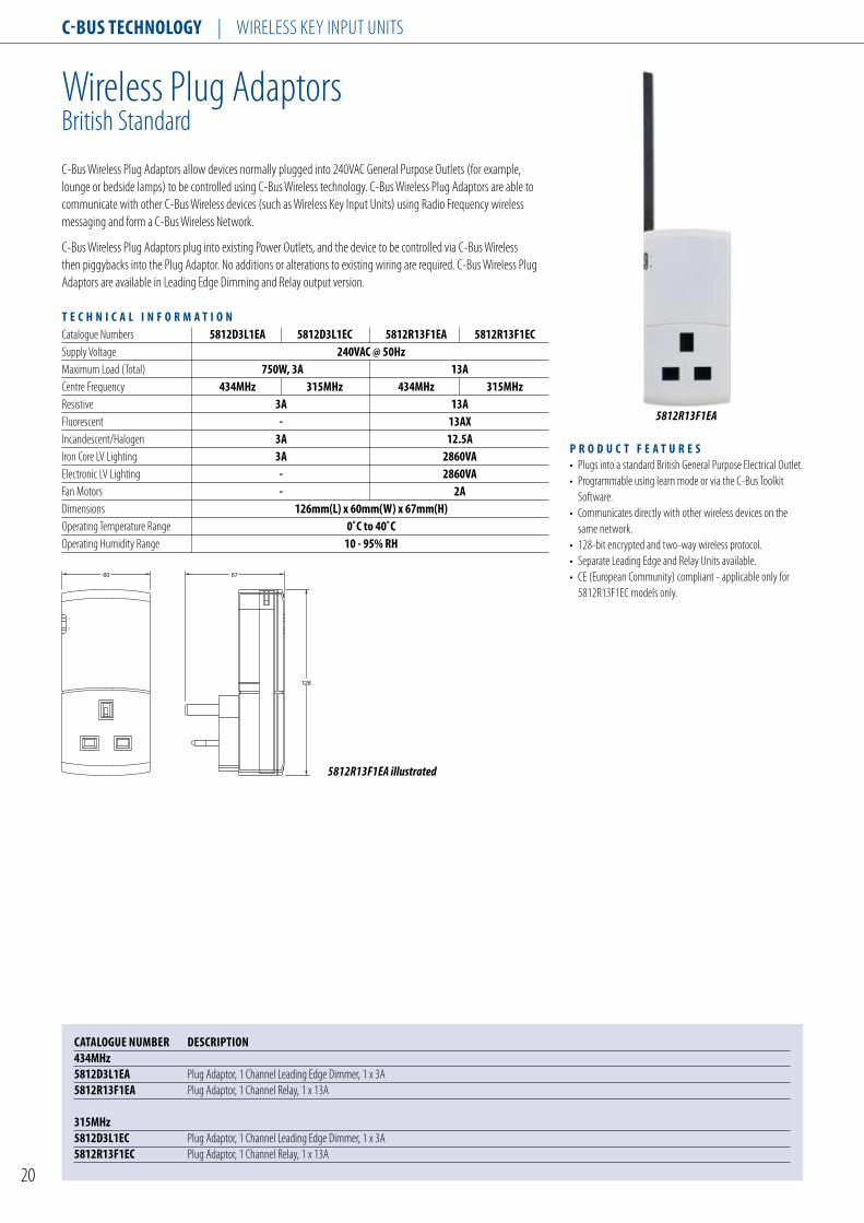
Wireless Plug AdaptorsBritish Standard
CATAlogue nuMBeR DesCRIPTIon434Mhz5812D3l1eA Plug Adaptor, 1 Channel Leading Edge Dimmer, 1 x 3A5812R13F1eA Plug Adaptor, 1 Channel Relay, 1 x 13A
315Mhz 5812D3l1eC Plug Adaptor, 1 Channel Leading Edge Dimmer, 1 x 3A5812R13F1eC Plug Adaptor, 1 Channel Relay, 1 x 13A
5812R13F1EA
C-Bus Wireless Plug Adaptors allow devices normally plugged into 240VAC General Purpose Outlets (for example, lounge or bedside lamps) to be controlled using C-Bus Wireless technology. C-Bus Wireless Plug Adaptors are able to communicate with other C-Bus Wireless devices (such as Wireless Key Input Units) using Radio Frequency wireless messaging and form a C-Bus Wireless Network.
C-Bus Wireless Plug Adaptors plug into existing Power Outlets, and the device to be controlled via C-Bus Wireless then piggybacks into the Plug Adaptor. No additions or alterations to existing wiring are required. C-Bus Wireless Plug Adaptors are available in Leading Edge Dimming and Relay output version.
T e C h n I C A l I n F o R M A T I o n Catalogue Numbers 5812D3l1eA 5812D3l1eC 5812R13F1eA 5812R13F1eCSupply Voltage 240VAC @ 50hz Maximum Load (Total) 750W, 3A 13ACentre Frequency 434Mhz 315Mhz 434Mhz 315MhzResistive 3A 13AFluorescent - 13AXIncandescent/Halogen 3A 12.5AIron Core LV Lighting 3A 2860VAElectronic LV Lighting - 2860VAFan Motors - 2ADimensions 126mm(l) x 60mm(W) x 67mm(h) Operating Temperature Range 0˚C to 40˚C Operating Humidity Range 10 - 95% Rh
P R o D u C T F e A T u R e s • Plugs into a standard British General Purpose Electrical Outlet.• Programmable using learn mode or via the C-Bus Toolkit Software.• Communicates directly with other wireless devices on the same network.• 128-bit encrypted and two-way wireless protocol.• Separate Leading Edge and Relay Units available.• CE (European Community) compliant - applicable only for 5812R13F1EC models only.

C-Bus TeChnology | WIRELESS KEy INPUT UNITS
21
Wireless Plug AdaptorsAustralian Standard
CATAlogue nuMBeR DesCRIPTIon5812D3l1AA Plug Adaptor, 1 Channel Leading Edge Dimmer, 1 x 3A5812D2T1AA Plug Adaptor, 1 Channel Trailing Edge Dimmer, 1 x 2A5812R10F1AA Plug Adaptor, 1 Channel Relay, 1 x 10A
C-Bus Wireless Plug Adaptors allow devices normally plugged into 240VAC General Purpose Outlets (for example, lounge or bedside lamps) to be controlled using C-Bus Wireless technology. C-Bus Wireless Plug Adaptors are able to communicate with other C-Bus Wireless devices (such as Wireless Key Input Units) using Radio Frequency wireless messaging and form a C-Bus Wireless Network.
C-Bus Wireless Plug Adaptors plug into existing Power Outlets, and the device to be controlled via C-Bus Wireless then piggybacks into the Plug Adaptor. No additions or alterations to existing wiring are required. C-Bus Wireless Plug Adaptors are available in Leading Edge Dimming and Trailing Edge Dimming Units, as well as a Relay output version.
T e C h n I C A l I n F o R M A T I o n Catalogue Numbers 5812D3l1AA 5812D2T1AA 5812R10F1AA Supply Voltage 240VAC @ 50hz Maximum Load (Total) 750W, 3A 500W, 2A 2400W, 10A Centre Frequency 434Mhz Fluorescent - - 4A Incandescent/Halogen 3A 2A 10A Iron Core LV Lighting 3A - 10AElectronic LV Lighting - 2A 10A Fan Motors - - 2A Dimensions 123mm(l) x 50mm(W) x 64mm(h) Operating Temperature Range 0˚C to 40˚C Operating Humidity Range 10 - 95% Rh
P R o D u C T F e A T u R e s • Plugs into a standard Australian General Purpose Electrical Outlet.• Programmable using learn mode or via the C-Bus Toolkit Software.• Communicates directly with other wireless devices on the same network.• 128-bit encrypted and two-way wireless protocol.• Separate Leading Edge, Trailing Edge and Relay Units available.• RCM (Australia/New Zealand) compliant.
5812D3L1AA
5812R10F1AA illustrated
122
30
40 21
35
41

C-Bus TeChnology | WIRELESS KEy INPUT UNITS
22
Wireless Remote Controls
The Wireless Remote Control has been designed to operate with all C-Bus radio frequency (RF) devices such as wall plates switches and dimmers and plug adaptors. The wireless remote control utilises RF communication, and unlike infrared remote controllers, there is no need for direct line of sight between the remote control and the unit being controlled.
The wireless protocol is based on the same protocol as wired C-Bus, for robustness and reliability and features 128-bit encrypted data for a highly secure network.
The remote control may be programmed to control up to 10 separate buttons located on wall plate switches, dimmers and plug adaptors. The remote control can also be programmed to operate devices in different networks. In addition a single button located on a wall switch, dimmer or plug adaptor may be related and control from two wireless remote control units.
The remote control is organized in two banks of five buttons - master off, raise and lower scene buttons - and LCD display used to indicate the scene or device under control.
The wireless remote control supports dimmer, toggle, on, off, timer and scene functions and may be programmed using learn mode.
T e C h n I C A l I n F o R M A T I o n Batteries 4 x AAA Alkaline batteries Centre Frequency 433.92Mhz/315MhzTransmitting Power 10mW No. of Device Buttons/Remote Unit 70m (open air) 20 - 25m (built-up area) Backlighting Blue leD Display lCD Dimension 149mm(l) x 52mm(W) x 26mm(D) Warm Up Time 5 seconds Operating Temperature Range 0˚C to 40˚C Operating Humidity Range 10 - 95% Rh
P R o D u C T F e A T u R e s • Walk around hand held remote control. • Two banks of five buttons (master off, raise and lower scene buttons). • LCD display window. • Button label option. • Transmit signal indicator. • Programming learn switch. • RCM (Australia/New Zealand) and CE (European Community) compliant.
5888TXBA
CATAlogue nuMBeR DesCRIPTIon 434Mhz 5888TXBA Remote Control, 8 Button
315Mhz 5888TXBC Remote Control, 8 Button
5888TXBA illustrated
LearnScenes Devices
Shift
AllOff
116
76 76

C-Bus TeChnology | WIRELESS KEy INPUT UNITS
23
Wireless Gateway
The Wireless Gateway is used to provide a seamless communications link between a wireless C-Bus network to a wired C-Bus network, providing interoperability of devices across these different transmission media.
With the Wireless Gateway, it is possible to control and monitor wireless devices from a wired C-Bus network device or application software such as Schedule Plus or HomeGate.
The Wireless Gateway is powered from the wired C-Bus network and a number of the Wireless Gateways may be connected to a wired C-Bus network if required.
The wireless protocol is based on the same protocol as wired C-Bus, for robustness and reliability and features 128-bit encrypted data for a highly secure network.
T e C h n I C A l I n F o R M A T I o n C-Bus Power Supply 15 - 36VDC @ 32mA Centre Frequency 433.92Mhz/315Mhz Transmitting Power 1mW Operating Distance 50m (open air) 15 - 20m (built-up area) Dimensions 105mm(W) x 149mm(h) x 26mm(D) Warm Up Time 5 seconds Operating Temperature Range 0˚C to 40˚C Operating Humidity Range 10 - 95% Rh
P R o D u C T F e A T u R e s • Facilitates a seamless integration between wired and wireless C-Bus networks. • Powered from a wired C-Bus network only, does not require an external plug pack. • Permits learn enabled operations from wired to wireless networks. • Supports routing of messages into and through wired and wireless networks. • Commands from one network (button presses) can be routed through to the other network. • RCM (Australia/New Zealand) and CE (European Community) compliant.
CATAlogue nuMBeR DesCRIPTIon 434Mhz 5800WCgA Gateway, Wired to Wireless C-Bus
315Mhz 5800WCgC Gateway, Wired to Wireless C-Bus
5800WCGA
105 26
145
5800WCGA illustrated

C-Bus TeChnology | key input units
24
C-Bus uLti Family key input unitswith Dynamic Labelling technology, British standard
E5084DL, GF
CATAlogue nuMBeR DesCRIPTIon e5084Dl key input, 4 Gang, LCDCover selection: (gF) White, (380) Cream, (680) Black, (780) Mid-Brown
e5084DF Fascia, Glass, 4 Gang for DLt switchColour selection: (gF) White, (380) Cream, (680) Black, (780) Mid-Brown
the Clipsal uLti Family Dynamic Labelling technology (DLt) switches are learn enabled, surface switches designed to control lighting and other electrical services connected to a C-Bus network. Dynamic Labelling technology allows the function of the key to be programmed and displayed onto a LCD display next to the switch button.
the display found on the DLt switch supports multi language text and user defined bitmaps, such as sliders and bar graphs. the LCD display incorporates back lighting that can be enabled for night operation. in addition, the DLt switch features a page scroll button that permits the user to navigate between pages, to access all control options.
key input units are fully programmable and may be configured as toggle, dimmer, timer or scene control type functions. With C-Bus switches it is possible to realise multi-way, multi-function switching or dimming control.
the DLt switches feature a glass fascia and are available in a range of colour backgrounds, including white, cream, black and mid-brown.
key input units communicate with all other units and obtain power via a single twisted pair of connections to the C-Bus. in the event of C-Bus power failure, non-volatile memory retains all programmed information relating to the unit’s operating status.
P R o D u C T F e A T u R e s • Available with 4 buttons (British standard). • Features blue light indicator with night light function. • supports text labels and user defined bitmaps. • ignore first press option. • Fallback to pages 1 and 2 option. • programmable using learn mode or via the C-Bus toolkit software. • programmed variables are stored in non-volatile memory and are retained in case of loss of C-Bus power. • Compatible with mounting accessories found in united kingdom, China, Malaysia, singapore, Middle east and other regions. • C-tick (Australia/new Zealand), Ce (european Community) compliant.
T e C h n I C A l I n F o R M A T I o n C-Bus supply Voltage 15 - 36V DC @ 22mA Maximum number of units 50on a single C-Bus network Button indicator Programmable, Blue timer Range 1 sec to 18 hrs timer Resolution 1 sec Dimmer Control 255 possible levels number of scenes 8 standard Colours White, Cream, Black and Mid-BrownWarm up time 5 seconds Operating temperature Range 0˚C to 45˚C Operating Humidity Range 10 - 95% Rh

C-Bus TeChnology | KEy INPUT UNITS
25
C-Bus ULTI Family Key Input Unitswith Dynamic Labelling Technology, Australian/US Standard
5085DL, GF
The Clipsal ULTI Family Dynamic Labelling Technology (DLT) switches are learn enabled, surface switches designed to control lighting and other electrical services connected to a C-Bus network. Dynamic Labelling Technology allows the function of the key to be programmed and displayed onto a LCD display next to the switch button.
The display found on the DLT switch supports multi language text and user defined bitmaps, such as sliders and bar graphs. The LCD display incorporates back lighting that can be enabled for night operation. In addition, the DLT switch features a page scroll button that permits the user to navigate between pages, to access all control options.
Key input units are fully programmable and may be configured as toggle, dimmer, timer or scene control type functions. With C-Bus switches it is possible to realise multi-way, multi-function switching or dimming control.
The DLT Switches feature a glass fascia and are available in a range of colour backgrounds, including white, cream, black and mid-brown.
Key input units communicate with all other units and obtain power via a single twisted pair of connections to the C-Bus. In the event of C-Bus power failure, non-volatile memory retains all programmed information relating to the unit’s operating status.
P R o D u C T F e A T u R e s • Available with 5 buttons (Australian/US standard). • Features blue light indicator with night light function. • Supports text labels and user defined bitmaps. • Ignore first press option. • Fallback to page 1 option. • Programmable using learn mode or via the C-Bus Toolkit Software. • Programmed variables are stored in non-volatile memory and are retained in case of loss of C-Bus power. • Compatible with mounting accessories found in United Kingdom, China, Malaysia, Singapore, Middle East and other regions. • C-Tick (Australia/New Zealand), CE (European Community) compliant.
T e C h n I C A l I n F o R M A T I o n C-Bus Supply Voltage 15 - 36V DC @ 22mA Maximum Number of Units 50on a Single C-Bus Network Button Indicator Programmable, Blue Timer Range 1 sec to 18 hrs Timer Resolution 1 sec Dimmer Control 255 possible levels Number of Scenes 8 Standard Colours White, Cream, Black and Mid-BrownWarm Up Time 5 seconds Operating Temperature Range 0˚C to 45˚C Operating Humidity Range 10 - 95% Rh
CATAlogue nuMBeR DesCRIPTIon 5085Dl Key Input, 5 Gang, LCDCover selection: (gF) White, (380) Cream, (680) Black, (780) Mid-Brown
5085DF Fascia, Glass, 5 Gang for DLT SwitchColour selection: (gF) White, (380) Cream, (680) Black, (780) Mid-Brown
116
76
13
28
70
42
5085DL illustrated

C-Bus TeChnology | KEy INPUT UNITS
26
C-Bus NEO Family Key Input Unitswith Dynamic Labelling Technology, British Standard
E5054DL, GB
CATAlogue nuMBeR DesCRIPTIon e5054Dl Key Input, 4 Gang, LCDCover selection: (We) White Electric, (sg) Soft Grey, (Ds) Desert Sand, (CM) Cream, (BR) Brown, (BK) Black, (gB) Battleship Grey
The Clipsal NEO Family Dynamic Labelling Technology (DLT) switches are learn enabled, surface switches designed to control lighting and other electrical services connected to a C-Bus network. Dynamic Labelling Technology allows the function of the key to be programmed and displayed onto a LCD display next to the switch button.
The display found on the DLT switch supports multi language text and user defined bitmaps, such as sliders and bar graphs. The LCD display incorporates back lighting that can be enabled for night operation. In addition the DLT switch features a page scroll button that permits the user to navigate between pages, to access all control options.
Key input units are fully programmable and may be configured as toggle, dimmer, timer or scene control type functions. With C-Bus switches it is possible to realise multi-way, multi-function switching or dimming control.
Key input units communicate with all other units and obtain power via a single twisted pair of connections to the C-Bus. In the event of C-Bus power failure, non-volatile memory retains all programmed information relating to the unit’s operating status.
P R o D u C T F e A T u R e s • Available with 4 buttons (British standard)• Features blue light indicator with night light function. • Supports text labels and user defined bitmaps. • Ignore first press option. • Fallback to pages 1 and 2 option. • Programmable using learn mode or via the C-Bus Toolkit Software. • Programmed variables are stored in non-volatile memory and are retained in case of loss of C-Bus power. • Compatible with mounting accessories found in United Kingdom, China, Malaysia, Singapore, Middle East and other regions. • C-Tick (Australia/New Zealand), CE (European Community) compliant.
T e C h n I C A l I n F o R M A T I o n C-Bus Supply Voltage 15 - 36VDC @ 22mA Maximum Number of Units 50 on a Single C- Bus Network Button Indicator Programmable, Blue Timer Range 1 sec to 18 hrs Timer Resolution 1 sec Dimmer Control 255 possible levels Number of Scenes 8 Standard Colours gB (Battleship grey) Warm Up Time 5 seconds Operating Temperature Range 0˚C to 45˚C Operating Humidity Range 10 - 95% Rh

C-Bus TeChnology | KEy INPUT UNITS
27
C-Bus NEO Family Key Input Unitswith Dynamic Labelling Technology, Australian/US Standard
5055DL, GB
CATAlogue nuMBeR DesCRIPTIon 5055Dl Key Input, 5 Gang, LCD Cover selection: (We) White Electric, (sg) Soft Grey, (Ds) Desert Sand, (CM) Cream, (BR) Brown, (BK) Black, (gB) Battleship Grey
T e C h n I C A l I n F o R M A T I o n C-Bus Supply Voltage 15 - 36VDC @ 22mA Maximum Number of Units 50 on a Single C- Bus Network Button Indicator Programmable, Blue Timer Range 1 sec to 18 hrs Timer Resolution 1 sec Dimmer Control 255 possible levels Number of Scenes 8 Standard Colours gB (Battleship grey) Warm Up Time 5 seconds Operating Temperature Range 0˚C to 45˚C Operating Humidity Range 10 - 95% Rh
116
76
13
28
70
42
5055DL illustrated
P R o D u C T F e A T u R e s • Available with 5 buttons (Australian/US standard) • Features blue light indicator with night light function. • Supports text labels and user defined bitmaps. • Ignore first press option. • Fallback to pages 1 and 2 option. • Programmable using learn mode or via the C-Bus Toolkit Software. • Programmed variables are stored in non-volatile memory and are retained in case of loss of C-Bus power. • Compatible with mounting accessories found in United Kingdom, China, Malaysia, Singapore, Middle East and other regions. • C-Tick (Australia/New Zealand), CE (European Community) compliant.
The Clipsal NEO Family Dynamic Labelling Technology (DLT) switches are learn enabled, surface switches designed to control lighting and other electrical services connected to a C-Bus network. Dynamic Labelling Technology allows the function of the key to be programmed and displayed onto a LCD display next to the switch button.
The display found on the DLT switch supports multi language text and user defined bitmaps, such as sliders and bar graphs. The LCD display incorporates back lighting that can be enabled for night operation. In addition the DLT switch features a page scroll button that permits the user to navigate between pages, to access all control options.
Key input units are fully programmable and may be configured as toggle, dimmer, timer or scene control type functions. With C-Bus switches it is possible to realise multi-way, multi-function switching or dimming control.
Key input units communicate with all other units and obtain power via a single twisted pair of connections to the C-Bus. In the event of C-Bus power failure, non-volatile memory retains all programmed information relating to the unit’s operating status.
C-Bus TeChnology | KEy INPUT UNITS
28
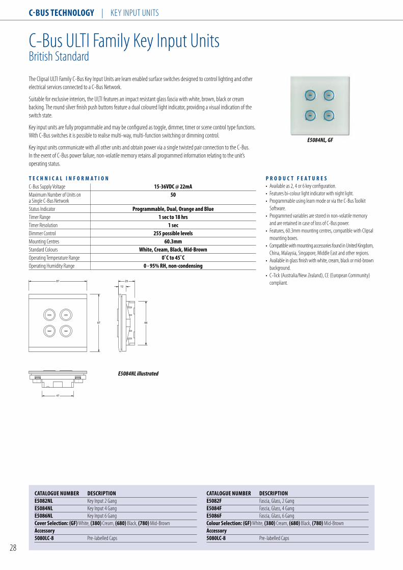
C-Bus ULTI Family Key Input UnitsBritish Standard
E5084NL, GF
The Clipsal ULTI Family C-Bus Key Input Units are learn enabled surface switches designed to control lighting and other electrical services connected to a C-Bus Network.
Suitable for exclusive interiors, the ULTI features an impact resistant glass fascia with white, brown, black or cream backing. The round silver finish push buttons feature a dual coloured light indicator, providing a visual indication of the switch state.
Key input units are fully programmable and may be configured as toggle, dimmer, timer or scene control type functions. With C-Bus switches it is possible to realise multi-way, multi-function switching or dimming control.
Key input units communicate with all other units and obtain power via a single twisted pair connection to the C-Bus. In the event of C-Bus power failure, non-volatile memory retains all programmed information relating to the unit’s operating status.
P R o D u C T F e A T u R e s • Available as 2, 4 or 6 key configuration. • Features bi-colour light indicator with night light. • Programmable using learn mode or via the C-Bus Toolkit Software. • Programmed variables are stored in non-volatile memory and are retained in case of loss of C-Bus power. • Features, 60.3mm mounting centres, compatible with Clipsal mounting boxes. • Compatible with mounting accessories found in United Kingdom, China, Malaysia, Singapore, Middle East and other regions. • Available in glass finish with white, cream, black or mid-brown background. • C-Tick (Australia/New Zealand), CE (European Community) compliant.
T e C h n I C A l I n F o R M A T I o n C-Bus Supply Voltage 15-36VDC @ 22mA Maximum Number of Units on 50 a Single C-Bus Network Status Indicator Programmable, Dual, orange and Blue Timer Range 1 sec to 18 hrs Timer Resolution 1 sec Dimmer Control 255 possible levels Mounting Centres 60.3mm Standard Colours White, Cream, Black, Mid-BrownOperating Temperature Range 0˚C to 45˚C Operating Humidity Range 0 - 95% Rh, non-condensing
87 66
87
12
25
47
E5084NL illustrated
CATAlogue nuMBeR DesCRIPTIon e5082nl Key Input 2 Gange5084nl Key Input 4 Gange5086nl Key Input 6 GangCover selection: (gF) White, (380) Cream, (680) Black, (780) Mid-BrownAccessory5080lC-8 Pre-labelled Caps
CATAlogue nuMBeR DesCRIPTIon e5082F Fascia, Glass, 2 Gange5084F Fascia, Glass, 4 Gange5086F Fascia, Glass, 6 GangColour selection: (gF) White, (380) Cream, (680) Black, (780) Mid-BrownAccessory5080lC-8 Pre-labelled Caps

C-Bus TeChnology | KEy INPUT UNITS
29
C-Bus ULTI Family Key Input UnitsAustralian/US Standard
5084NL, GF
CATAlogue nuMBeR DesCRIPTIon 5082nl Key Input 2 Gang5084nl Key Input 4 Gang5086nl Key Input 6 GangCover selection: (gF) White, (380) Cream, (680) Black,(780) Mid-Brown
CATAlogue nuMBeR DesCRIPTIon5082F Fascia, Glass, 2 Gang5084F Fascia, Glass, 4 Gang5086F Fascia, Glass, 6 GangColour selection: (gF) White, (380) Cream, (680) Black,(780) Mid-Brown
The Clipsal ULTI Family C-Bus Key Input Units are learn enabled surface switches designed to control lighting and other electrical services connected to a C-Bus Network.
Suitable for exclusive interiors, the ULTI features an impact resistant glass fascia with white, brown, black or cream backing. The round silver finish push buttons feature a dual coloured light indicator, providing a visual indication of the switch state.
Key input units are fully programmable and may be configured as toggle, dimmer, timer or scene control type functions. With C-Bus switches it is possible to realise multi-way, multi-function switching or dimming control.
Key input units communicate with all other units and obtain power via a single twisted pair connection to the C-Bus. In the event of C-Bus power failure, non-volatile memory retains all programmed information relating to the unit’s operating status.
P R o D u C T F e A T u R e s • Available as 2, 4 or 6 key configuration. • Features bi-colour light indicator with night light. • Programmable using learn mode or via the C-Bus Toolkit Software. • Programmed variables are stored in non-volatile memory and are retained in case of loss of C-Bus power. • Features, 84mm mounting centres, compatible with Clipsal mounting boxes. • Compatible with mounting accessories found in Australia, New Zealand, United States, Thailand, Taiwan, Korea and others. • Available in glass finish with white, black, cream or mid-brown background. • C-Tick (Australia/New Zealand), CE (European Community) compliant.
T e C h n I C A l I n F o R M A T I o n C-Bus Supply Voltage 15-36VDC @ 22mA Maximum Number of Units on 50 a Single C-Bus Network Status Indicator Programmable, Dual, orange and Blue Timer Range 1 sec to 18 hrs Timer Resolution 1 sec Dimmer Control 255 possible levels Mounting Centres 84mm Standard Colours White, Cream, Black, Mid-Brown Operating Temperature Range 0˚C to 45˚C Operating Humidity Range 0 - 95% Rh, non-condensing
5086F, 380
116 66
76
12
25
47
5084NL illustrated

C-Bus TeChnology | KEy INPUT UNITS
30
C-Bus NEO Family Key Input UnitsBritish Standard
E5058NL, GB
CATAlogue nuMBeR DesCRIPTIon e5052nl Key Input 2 Gange5054nl Key Input 4 Gange5058nl Key Input 8 GangCover selection: (We) White Electric, (sg) Soft Grey, (Ds) Desert Sand, (CM) Cream, (BR) Brown, (BK) Black, (gB) Battleship Grey
The Clipsal NEO Family C-Bus Key Input Units are learn enabled surface switches designed to control lighting and other electrical services connected to a C-Bus Network.
Suitable for exclusive interiors, the NEO features large, flat, tactile rocker action switches that have been designed to blend in with the fascia. The NEO switches feature a bi-colour light indicator that provides a visual indication of switch status.
The NEO switches feature a night light function, and incorporate an infrared receiver in the body of the unit, so the switch may be used with a remote control.
Key input units are fully programmable and may be configured as toggle, dimmer, timer or scene control type functions. With C-Bus switches it is possible to realise multi-way, multi-function switching or dimming control.
Key input units communicate with all other units and obtain power via a single twisted pair connection to the C-Bus. In the event of C-Bus power failure, non-volatile memory retains all programmed information relating to the unit’s operating status.
The NEO switches are available in a wide range of colours and finishes.
P R o D u C T F e A T u R e s • Available as 2, 4 or 8 key configuration. • Features bi-colour light indicator with night light function. • Built in infrared receiver. • Programmable using learn mode or via the C-Bus Toolkit Software. • Programmed variables are stored in non-volatile memory and are retained in case of loss of C-Bus power. • Features 60.3mm mounting centres, compatible with Clipsal mounting boxes. • Compatible with mounting accessories found in United Kingdom, China, Malaysia, Singapore, Middle East and other regions. • Compatible with 5038TX infrared remote control. • C-Tick (Australia/New Zealand), CE (European Community) compliant.
T e C h n I C A l I n F o R M A T I o n C-Bus Supply Voltage 15-36VDC @ 22mA Maximum Number of Units on 50 a Single C-Bus Network Status Indicator Programmable, Dual, orange and Blue Timer Range 1 sec to 18 hrs Timer Resolution 1 sec Dimmer Control 255 possible levels Mounting Centres 60.3mm Standard Colours We, sg, Ds, CM, BR, BK and gB Standard Colours (Inner Surround) BA and gD Operating Temperature Range 0˚C to 45˚C Operating Humidity Range 0 - 95% Rh, non-condensing
87 sq.
65
50
22
E5058NL illustrated

C-Bus TeChnology | KEy INPUT UNITS
31
C-Bus NEO Family Key Input UnitsAustralian Standard
5058NL, GB
The Clipsal NEO Family C-Bus Key Input Units are learn enabled surface switches designed to control lighting and other electrical services connected to a C-Bus Network.
Suitable for exclusive interiors, the NEO features large, flat, tactile rocker action switches that have been designed to blend in with the fascia. The NEO switches feature a bi-colour light indicator that provides a visual indication of switch status.
The NEO switches feature a night light function, and incorporate an infrared receiver in the body of the unit, so the switch may be used with a remote control.
Key input units are fully programmable and may be configured as toggle, dimmer, timer or scene control type functions. With C-Bus switches it is possible to realise multi-way, multi-function switching or dimming control.
Key input units communicate with all other units and obtain power via a single twisted pair connection to the C-Bus. In the event of C-Bus power failure, non-volatile memory retains all programmed information relating to the unit’s operating status.
The NEO switches are available in a wide range of colours and finishes.
P R o D u C T F e A T u R e s • Available as 2, 4 or 8 key configuration. • Features bi-colour light indicator with night light function. • Built-in infrared receiver. • Programmable using learn mode or via the C-Bus Toolkit Software. • Programmed variables are stored in non-volatile memory and are retained in case of loss of C-Bus power. • Features 84mm mounting centres, compatible with Clipsal mounting boxes. • Compatible with mounting accessories found in United Kingdom, China, Malaysia, Singapore, Middle East and other regions. • Compatible with 5038TX infrared remote control. • C-Tick (Australia/New Zealand), CE (European Community) compliant.
T e C h n I C A l I n F o R M A T I o n C-Bus Supply Voltage 15-36VDC @ 22mA Maximum Number of Units on 50 a Single C-Bus Network Status Indicator Programmable, Dual, orange and Blue Timer Range 1 sec to 18 hrs Timer Resolution 1 sec Dimmer Control 255 possible levels Mounting Centres 84mm Standard Colours We, sg, Ds, CM, BR, BK and Bg Standard Colours (Inner Surround) BA and gD Operating Temperature Range 0˚C to 45˚C Operating Humidity Range 0 - 95% Rh, non-condensing
CATAlogue nuMBeR DesCRIPTIon 5052nl Key Input 2 Gang5054nl Key Input 4 Gang5058nl Key Input 8 GangCover selection: (We) White Electric, (sg) Soft Grey, (Ds) Desert Sand, (CM) Cream, (BR) Brown, (BK) Black, (gB) Battleship GreyAccessory5050sD Spacers to Suit NEO Australia/US Standard Switches
65
50
116
2276
5058NL illustrated

C-Bus TeChnology | KEy INPUT UNITS
32
C-Bus Remote Controls
CATAlogue nuMBeR DesCRIPTIon 5084TX IR Remote Control, Long Range, 4 Button 5088TX IR Remote Control, Long Range, 8 Button5088TXC C-Bus Remote Control Holder (Spare)
5038TX
Accessories for C-Bus ULTI Family Key Input Units
CATAlogue nuMBeR DesCRIPTIon5080lC-8 Pre-labelled Caps5850F Mounting Frames to Suit C-Bus ULTI Australian/US Standard Switches (Pack of 5)Cover selection: (We) White Electric, (sg) Soft Grey, (Ds) Desert Sand, (CM) Cream, (BR) Brown, (BK) Black
5084TX
5080LC-8
5088TX
149
52 24
149
52 24
5038TX illustrated 5084TX illustrated 5088TX illustrated

C-Bus TeChnology | KEy INPUT UNITS
33
E5050OS 5050OS 5052NRP, 2
CATAlogue nuMBeR DesCRIPTIon Inner surroundse5050Is Inner Surround, British Standard (Pack of 5)5050Is Inner Surround, Australian/US Standard (Pack of 5)
outer surroundse5050os Outer Surround, British Standard (Pack of 5)5050os Outer Surround, Australian/US Standard (Pack of 5)
Rocker switch Covers and spacers5052nRP Rocker Switch Covers and Spacers for E5052NL and 5052NL (Pack of 5 Rocker Switch Covers and 10 Spacers)5054nRP Rocker Switch Covers and Spacers for E5054NL and 5054NL (Pack of 10 Rocker Switch Covers and 10 Spacers)5058nRP Rocker Switch Covers and Spacers for E5058NL and 5058NL (Pack of 20 Rocker Switch Covers)
Rocker switch Covers with ID Window5052nRI Rocker Switch Cover with ID Window (Pack of 10 Rocker Switch Covers)
Colour selection: (gB) Battleship Grey, (We) White, (CM) Cream, (sg) Soft Grey, (Ds) Desert Sand, (BK) Black, (BR) Brown, (BA) Brushed Aluminium*, (gD) Gold**For Inner Surrounds only.
Accessories for C-Bus NEO Family Key Input Units
E5050IS 5050IS
5052NRI, 2
5052NRI, 1

C-Bus TeChnology | KEy INPUT UNITS
34
Reflection Key Input UnitsAustralian/US Standard
R5068NL
CATAlogue nuMBeR DesCRIPTIon R5061nl Key Input 1 Gang R5062Vnl Key Input 2 Gang, Vertical R5063nl Key Input 3 Gang R5064Vnl Key Input 4 Gang, Vertical R5066nl Key Input 6 Gang R5068nl Key Input 8 Gang AccessoryR5060WB Wall Box for Reflection Series
The Clipsal Reflections Series C-Bus Key Input Units are learn enabled, ultra flat, surface switches designed to control lighting and other electrical services connected to a C-Bus Network.
Suitable for exclusive interiors, the Reflection switches feature a screwless, high grade, stainless steel metal cover. The screwless design means that the aesthetics and architectural finish of the product provides a clean, stylish appearance.
The Reflection series also feature square, backlit, metal finish switch to maintain the aesthetics of the switch plate.
Key input units are fully programmable and may be configured as toggle, dimmer, timer or scene control type functions. With C-Bus switches it is possible to realise multi-way, multi-function switching or dimming control.
Key input units communicate with all other units and obtain power via a single twisted pair connection to the C-Bus. In the event of C-Bus power failure, non-volatile memory retains all programmed information relating to the unit’s operating status.
P R o D u C T F e A T u R e s • Available as 1, 2, 3, 4, 6 and 8 key configuration. • Features blue light indicator with night light. • Programmable using learn mode or via the C-Bus Toolkit Software. • Programmed variables are stored in non-volatile memory and are retained in case of loss of C-Bus power. • Features 84mm mounting centres (requires special wallbox for mounting). • C-Tick (Australia/New Zealand), CE (European Community) compliant.
T e C h n I C A l I n F o R M A T I o n C-Bus Supply Voltage 15-36VDC @ 20mA Maximum Number of Units on 50 a Single C-Bus Network Status Indicator Programmable, Blue leD Timer Range 1 sec to 18 hrs Timer Resolution 1 sec Dimmer Control 255 possible levels Mounting Centres 84mm Operating Temperature Range 0˚C to 45˚C Operating Humidity Range 0 - 95% Rh, non-condensing
R5060WB70
72
31
50
115
R5068NL illustrated

C-Bus TeChnology | SySTEM UNITS
35
Ethernet Network Interface
5500CN
CATAlogue nuMBeR DesCRIPTIon 5500Cn Computer Network Interface, 10 Base-T
The Ethernet Network Interface is a C-Bus device designed to provide an isolated communications path between an Ethernet 10 Base-T network and C-Bus network. This allows high-speed control and monitoring of a C-Bus installation via the TCP/IP protocols used in computer networks and by the Internet.
The Network Interface is a near instantaneous connection to a C-Bus network. It provides a gateway between high-speed, high bandwidth Ethernet communication and the robust, time tested Clipsal C-Bus Control System.
In addition to programming, the Network Interface provides similar convenience for third party applications to issue commands to a C-Bus network and monitor the behavior of units on the network. The Network Interface is assigned an IP address, just like a PC on a computer network. Once an IP address is assigned it is possible for a myriad of applications, applets and third party system to send C-Bus commands to the C-Bus network remotely.
T e C h n I C A l I n F o R M A T I o n Catalogue Number 5500Cn C-Bus Supply Voltage 15-36VDC @ 22mA Ethernet Supply Voltage 9-12VAC/DC Network Speed 10 Base-T Network Protocol TCP/IP Status Indicators network and C-Bus Network Burden software selectable System Clock software selectable C-Bus Termination 2 x RJ45 sockets Ethernet Termination 1 x RJ45 socket, shieldedPower Pack not includedOperating Temperature Range 0˚C to 45˚C Operating Humidity Range 0 - 95% Rh, non-condensing
P R o D u C T F e A T u R e s • Provides a TCP/IP interface to the C-Bus network. • Provides high-speed backbone communications path. • Permits any size C-Bus networks, overcomes restrictions of network size when Network Bridges are used. • Programmable via the C-Bus configuration software. • Programmed variables are stored in non-volatile memory and are retained in case of loss of C-Bus power. • Designed to fit standard 35mm top hat DIN rail, measures just 4M in size. • Designed to fit into standard electrical switchboards. • C-Tick (Australia/New Zealand), CE (European Community) compliant.
R
C-Bus/Unit/Comms
Ethernet
Network Interface
9 - 12V ETHERNET
72
65
32
18
15
456885
C-Bus CONNECTIONS
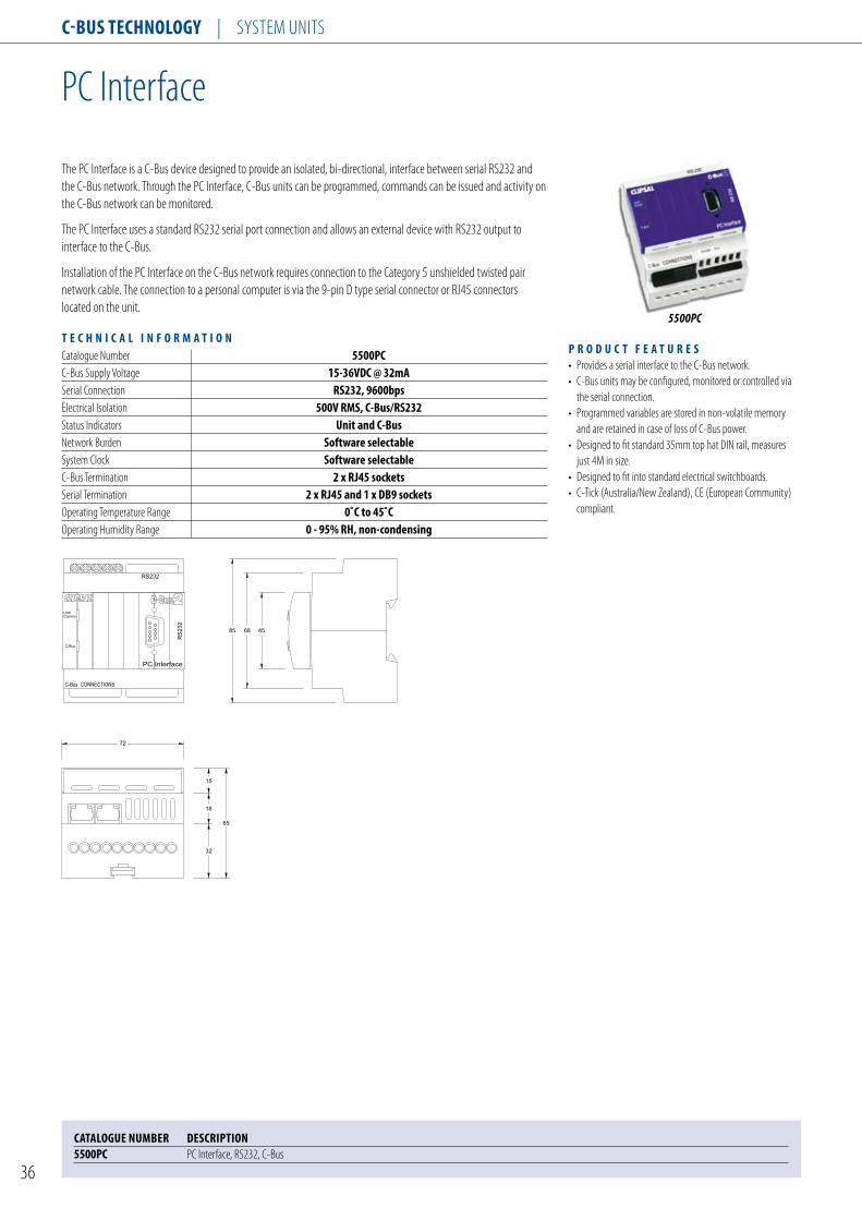
C-Bus TeChnology | SySTEM UNITS
36
PC Interface
5500PC
CATAlogue nuMBeR DesCRIPTIon 5500PC PC Interface, RS232, C-Bus
The PC Interface is a C-Bus device designed to provide an isolated, bi-directional, interface between serial RS232 and the C-Bus network. Through the PC Interface, C-Bus units can be programmed, commands can be issued and activity on the C-Bus network can be monitored.
The PC Interface uses a standard RS232 serial port connection and allows an external device with RS232 output to interface to the C-Bus.
Installation of the PC Interface on the C-Bus network requires connection to the Category 5 unshielded twisted pair network cable. The connection to a personal computer is via the 9-pin D type serial connector or RJ45 connectors located on the unit.
P R o D u C T F e A T u R e s • Provides a serial interface to the C-Bus network. • C-Bus units may be configured, monitored or controlled via the serial connection. • Programmed variables are stored in non-volatile memory and are retained in case of loss of C-Bus power. • Designed to fit standard 35mm top hat DIN rail, measures just 4M in size. • Designed to fit into standard electrical switchboards. • C-Tick (Australia/New Zealand), CE (European Community) compliant.
T e C h n I C A l I n F o R M A T I o n Catalogue Number 5500PC C-Bus Supply Voltage 15-36VDC @ 32mA Serial Connection Rs232, 9600bps Electrical Isolation 500V RMs, C-Bus/Rs232 Status Indicators unit and C-Bus Network Burden software selectable System Clock software selectable C-Bus Termination 2 x RJ45 sockets Serial Termination 2 x RJ45 and 1 x DB9 sockets Operating Temperature Range 0˚C to 45˚C Operating Humidity Range 0 - 95% Rh, non-condensing
C-Bus
Unit/Comms
PC Interface
RS232
R
72
65
32
18
15
456885
RS
232
C-Bus CONNECTIONS

C-Bus TeChnology | SySTEM UNITS
37
C-Bus® USB PC Interface
CATAlogue nuMBeR DesCRIPTIon 5500PCu C-Bus® USB PC Interface
The DIN rail mounted C-Bus USB PC Interface is a C-Bus system device designed to provide a gateway between a PC and C-Bus network. Through the C-Bus USB PC Interface, C-Bus units can be programmed, commands can be issued to the C-Bus network and activity on the C-Bus network can be monitored.
The C-Bus USB PC Interface uses a USB Type B socket and allows a PC with USB output to be interfaced to a C-Bus system. A 1 meter Type A to Type B USB cable is provided to connect the 5500PCU to a PC.
The USB PC Interface can be programmed to generate the C-Bus system clock for communications data synchronization on the C-Bus network and also provides a software selectable network burden.
Installation of the C-Bus USB PC Interface on the C-Bus network requires connection to the Category 5 unshielded twisted pair C-Bus network cable. The connection to a personal computer is via the Type A to Type B USB cable provided with the unit, as per above.
The unit incorporates C-Bus and Unit/Communications LED indicators. These LEDs indicate if the unit is powered and functional, if sufficient C-Bus network voltage is available, if a valid C-Bus clock is present and if data transfer is currently taking place.
T e C h n I C A l I n F o R M A T I o n Catalogue Numbers 5500PCu C-Bus supply voltage 15 to 36 VDC @22mA Does not supply current to the C-Bus networkC-Bus AC input impedance 100 kΩ @ 1khzC-Bus system clock software selectableNetwork burden software selectableOperation temperature range 0 to 45ºC (32 to 113ºF)Operating humidity range 10 to 95% RhDimensions (W x H x D) 72 x 92 x 63 mmWeight 92gC-Bus Connections 2 x RJ45 sockets (in parallel)PC Connection 1 x usB type B
P R o D u C T F e A T u R e s • Provides a gateway between a PC and a C-Bus Network via USB connection• DIN Rail mounted• 4 DIN modules wide• Requires connection to a C-Bus network via an unshielded twisted pair C-Bus network cable• 2 x RF45 sockets provided for C-Bus connections• Connection to a personal computer via a Type B socket located on the unit and a Type A to Type B USB cable (supplied)• Capable of generating a C-Bus system clock for communications data synchronization• Provides a software selectable network burden• Consumes 32mA from the C-Bus network• Incorporates a Unit/Communications LED indicator• Incorporates a C-Bus LED indicator• CE, FCC compliant
5500PCU

C-Bus TeChnology | SySTEM UNITS
38
Network Bridge
5500NB
CATAlogue nuMBeR DesCRIPTIon 5500nB Network Bridge
The Network Bridge is a network support device that provides an isolated communications channel between C-Bus units on separate networks. Both sides of the network bridge are optically isolated, providing electrical isolation between adjacent networks.
Network bridges are required to manage networks to particular units in particular zones, or to extend the network past system limitations of 100 passive units and 1000 metres of C-Bus cable in any one network.
T e C h n I C A l I n F o R M A T I o n Catalogue Number 5500nB C-Bus Supply Voltage 15-36VDC @ 20mA Electrical Isolation rating 3,500V RMs (opto-isolated, 1 minute) (between networks) Maximum Number of Units on 100 a Single C-Bus Network Status Indicators network 1 and network 2 C-Bus Termination 4 x RJ45 sockets (network 1 and 2) Operating Temperature Range 0˚C to 45˚C Operating Humidity Range 0 - 95% Rh, non-condensing
P R o D u C T F e A T u R e s • Provides an isolated communications path between networks. • Programmable via the C-Bus configuration software. • Programmed variables are stored in non-volatile memory and are retained in case of loss of C-Bus power. • Designed to fit standard 35mm top hat DIN rail, measures just 4M in size. • Designed to fit into standard electrical switchboards. • C-Tick (Australia/New Zealand), CE (European Community) compliant.
Network B
Network A
Network Bridge
R
72
65
32
18
15
456885
C-Bus CONNECTIONS
C-Bus CONNECTIONS

C-Bus TeChnology | SySTEM UNITS
39
Power Supply
5500PS
CATAlogue nuMBeR DesCRIPTIon 5500Ps Power Supply, 220/240VAC, 50/60Hz, 350mAe5500TPs Power Supply, 110/120VAC, 50/60Hz, 350mA
The Power Supply converts the line voltage input to 36VDC output, required for correct operation by C-Bus devices. The power supply can source up to 350mA to the network and power supplies may be added in parallel as more C-Bus devices are added to the network, under these conditions the power supplies share the load current equally.
The power supplies feature short circuit and reverse polarity protection and the line voltage is galvonically isolated from the C-Bus output side.
T e C h n I C A l I n F o R M A T I o n Catalogue Numbers 5500Ps e5500TPs Line Supply Voltage 220-240VAC 110-120VACSupply Frequency 47-53hz and 57-63hz Output Voltage 32-39VDC Output Current 350mA (maximum) Duration of Short Circuit on Output Indefinite AC Isolation Mains/C-Bus 3,750V RMs Warm-Up Time 3 seconds Number of C-Bus Units, 19 Supported by one Power Supply (Standard passive unit = 18mA) Maximum Number of Units on 5a Single C-Bus Network Maximum Voltage Drop Measured 10VDC between Power Supply and Passive C-Bus Unit for Correct Operation Status Indicators unit and C-Bus C-Bus Termination 2 x RJ45 sockets Line Termination 2 x 1.5mm2 or 1 x 2.5mm2 Operating Temperature Range 0˚C to 45˚C Operating Humidity Range 0 - 95% Rh, non-condensing
P R o D u C T F e A T u R e s • Delivers up to 350mA to the C-Bus Network. • High efficiency switched mode power supply design. • Units may be operated in parallel on the same network. • Does not require programming on installation. • Designed to fit standard 35mm top hat DIN rail, measures just 4M in size. • Designed to fit into standard electrical switchboards. • RCM (Australia/New Zealand), CE (European Community) compliant.
C-Bus
Unit
Power Supply
R
72
65
32
18
15
456885
C-Bus CONNECTIONS
N A/L
E5500TPS illustrated

C-Bus TeChnology | SySTEM UNITS
40
Network Analyser
5100NA
CATAlogue nuMBeR DesCRIPTIon 5100nA Network Analyser
The Network Analyser is a field diagnostic tool designed to measure and report the status of various network parameters.
The network analyser connects to the C-Bus network and is used to measure the network voltage, active clock and network impedance and determine if these are within acceptable limits for correct operation.
The unit displays the results by illuminating LEDs located on the unit.
Note: The network analyser should be used in conjunction with the C-Bus Calculator software application.
T e C h n I C A l I n F o R M A T I o n Catalogue Numbers 5100nA C-Bus Supply Voltage 15-36VDC @ 20mA Status Indicators Power available Clock not present excess voltage Remove burden Add burden excess cable C-Bus Termination 2 x Alligator clips Operating Temperature Range 0˚C to 45˚C Operating Humidity Range 0 - 95% Rh, non-condensing
CAT No.5100NANetwork Analyser
Power Available
Clock Not Present
Excess Voltage
Remove Burden
Add Burden
Excess Cable
NetworkBurden
Hold down to add to network
30
118
60

C-Bus TeChnology | SySTEM UNITS
41
45
12 11
Network Burden
CATAlogue nuMBeR DesCRIPTIon 5000BuR C-Bus Network Burden, RJ45 (Pack of 10)
5000BUR

C-Bus TEChnology | Input unIts
42
C-Bus Zone thermostat
CATAloguE nuMBER DEsCRIPTIon single zone Thermostat5070ThBRPg, WE single zone thermostat complete with 5 relays for RWG plant control only, white Fascia ,saturn style5070ThBR, BK single Zone thermostat complete with 5 relays for RWG plant control only, Black Fascia5070ThBRss single Zone thermostat complete with 5 relays for RWG plant control only, stainless steel fascia5070ThBPg, WE single Zone thermostat- no on-board relays, White Fascia (saturn style)5070ThB, BK single Zone thermostat-no on-board relays, Black Fascia5070ThBss single Zone thermostat-no on-board relays, stainless steel Fascia
4 Zone Thermostat with Programmable Time scheduling5070ThPRPg, WE programmable 4 Zone thermostat complete with 5 relays for RWG plant control only, white Fascia ,saturn style5070ThPR, BK programmable 4 Zone thermostat complete with 5 relays for RWG plant control only, Black Fascia5070ThPRss programmable 4 Zone thermostat complete with 5 relays for RWG plant control only, stainless steel Fascia5070ThPPg, WE programmable 4 Zone thermostat- no on-board relays, White Fascia (saturn style)5070ThP, BK programmable 4 Zone thermostat-no on-board relays, Black Fascia5070ThPss programmable 4 Zone thermostat-no on-board relays, stainless steel Fascia5031RDTsl Remote temperature sensor with broadcasting for Four Zone thermostat (to be released)
the 5070tHB series C-Bus single Zone thermostat is used to control heating/ventilation/air conditioning (HVAC) equipment, regulating the air temperature of a particular environment.
the 5070tHBR model has built-in relays that can be connected to HVAC equipment which uses a standard 24 V AC RWG interface. the 5070tHB model connects to HVAC equipment via an external C-Bus Relay unit (such as the 5508RVF). Apart from this, both models have the same features.
the air temperature is monitored by the unit’s internal temperature sensor or optionally via an external C-Bus temperature sensor.
T E C h n I C A l I n F o R M A T I o n Catalogue numbers 5070ThB C-Bus supply Voltage 15-36V DC, 40mA Does not provide current to the C-Bus networkC-Bus AC Input Impedance 50kΩ @ 1khzRelays (5070tHpR model) Each relay rated at 2A @24V AC 3750V Isolation between terminals and C-BusC-Bus Connection one terminal block to accommodate 0.2 to 1.3mm2 (24 to 16 AWg)temperature sensor Accuracy =/- 0.5 °C (+/- 0.9 °F)C-Bus system Clock software selectablenetwork Burden software selectableOperating temperature -10 to 50 °C (14 to 122 °F)Operating Humidity Range 10 to 95% R.h.Dimensions (W x H x D) 150 x 105 x 32mm 127 × 92 × 27mmMounting Centres 84 mm (horizontal) 60.3 mm (vertical)Weight 5070ThBss: 265 g (Models with stainless steel Fascia) 5070ThBRss: 280 g 5070ThBss: 265 g 5070ThBRss: 280 g
P R o D u C T F E A T u R E s • support for control of HVAC units via C-Bus or internal relays (‘RWG’ control).• Zone control of up to four switched zones for ducted systems (plus the common zone).• 7 day programmable HVAC schedules.• support for remote temperature sensing by other C-Bus devices.• Optional manual fan speed control (for HVAC plant that supports variable fan speeds).• setback capability for reducing energy consumption.
5070THBR

C-Bus TEChnology | Output unIts
43
C-Bus Motorized Blinds/Curtains/shutter Relay, 250VAC, no C-Bus power supply
CATAloguE nuMBER DEsCRIPTIon l5501RBCP C-Bus Motorized Blinds/Curtains/shutter Relay, 250VAC, no C-Bus power supply5501RE C-Bus Motorized Blinds/Curtains/shutter Relay Enclosure
the L5501RBCp C-Bus shutter Relay is a single channel output unit suitable for controlling motorised curtains, blinds and shutters. the unit has voltage free terminals with separate outputs for open/up and close/down.
Any motor running at mains power or 24V AC, rated at up to 2A (M) and intended for blinds, curtains or shutter control can be connected to the L5501RBCp C-Bus shutter Relay.
Each unit is used to control one set of motorised blinds, curtains or shutters. It contains one isolated channel for Close, Open and stop control.
the C-Bus shutter Relay can be programmed to generate the C-Bus system clock for communications data synchronization on the C-Bus network and also provides a software selectable network Burden.
two local override buttons are provided for Close and Open functions (overriding the current C-Bus state).
T E C h n I C A l I n F o R M A T I o n Catalogue numbers l5501RBCP C-Bus supply Voltage 15 to 36 V DC @ 22 mA Does not supply power to the C-Bus networkAC Input Impedance 80kΩ @ 1kHzElectrical Isolation 3.75kV RMs from C-Bus to mainsMax. units per network 80Load Current Rating 2A (motor load)Load Voltage Rating 24V DC, 24-240V ACWarm up time 5 secondsnetwork Clock software selectablenetwork Burden software selectable when unit Address is 001Class of switch Class IIRated Impulse Withstand Voltage 4 kVproof tracking index (ptI) 175Level 3 glow wire 850 °Cswitch duty type (s2) Momentary dutyOperating temperature 0 to 55 °C (32 to 131 °F)Operating Humidity 10 to 95% RHDimensions (W x H x D) 36 × 93 × 63 mm (2.83 × 3.35 × 2.56 inches)Weight 250 g (0.552 lbs)Mains terminals Accommodates 2 × 1.5 mm2 or 1 × 2.5 mm2 (2 × 15 AWG or 1 × 13 AWG), suitable for flexible and rigid/solid conductors, prepared and unprepared (with or without bootlace ferrules)
P R o D u C T F E A T u R E s • One, two or three button control• Electrically Interlocked Relays• suitable for both AC and DC motors• Optional ‘field-mount’ enclosure• Direct Motor Control• Local manual override buttons
L5501RBCP

C-Bus TEChnology | Input unIts
44
General Input unit
the C-Bus 4 Channel General Input units are DIn rail mount units designed to measure digital, voltage, current loop and thermistor inputs and generate messages to the C-Bus network.
the unit is designed to broadcast the actual measured value to the C-Bus network, which in turn may be displayed on other C-Bus devices such as the touch screen, C-Gate or C-Lution. In addition, the unit may trigger a Group Address as a function of the input level, up to eight trigger points may be assigned to a single input channel.
the general input unit is designed to interface to third party products, such as light level sensors, temperature sensors, power, frequency, moisture, rate sensors and others. In this way, the general input may be used to extend the functionality of the C-Bus and its ability to integrate with other systems such as HVAC and power monitoring systems. the general input also generates 24VDC to power the external sensors.
the general input units are available as passive models only, hence do not source current to the C-Bus network.
T E C h n I C A l I n F o R M A T I o nCatalogue number E5504gIsupply Voltage 24VAC +/- 10% @ 500mA, power pack not supplied with the unitsupply Frequency 50/60hzC-Bus supply Voltage 15-36VDC @ 18mAAuxiliary Output 24VDC @ 250mAVoltage Inputs 0 - 1V, 0 - 5V, 0 - 10V and 0 - 20VCurrent Inputs 0 - 20mA and 4 - 20mAImpedance Inputs 0 - 500Ω, 0-1kΩ and 0-3kΩDigital Inputs yesBroadcast Rate 2 to 1,024 secondsMaximum number of units on 10a single C-Bus networkstatus Indicators unit and C-BusA/D Conversion 8 - bitAccuracy 0.5%Warm up time 5 secondsnetwork Clock software selectablenetwork Burden software selectableC-Bus termination 2 x RJ45 socketLoad termination 2 x 1.5mm2 or 1 x 2.5mm2Operating temperature Range 0˚C to 45˚COperating Humidity Range 0 - 95% Rh, non-condensing
P R o D u C T F E A T u R E s• provides 4 channels of input, compatible with a range of third party sensor products.• Capable of threshold switching or broadcasting value onto the network.• programmable via the C-Bus toolkit software.• programmed variables are stored in non-volatile memory and are retained in case of loss of mains or C-Bus power.• Designed to fit standard 35mm top hat DIn rail, measures just 8M in size.• Designed to fit into standard electrical switchboards. • C-tick (Australia/new Zealand), CE (European Community) compliant.
CATAloguE nuMBER DEsCRIPTIon5504gI 4 Channel General Input unit
E5504GI
C-Bus
Unit-Comm
General Input
A
143
65
32
18
15
456885
1 B24 COMVDC OUTV IN
24COM24 A 4 BA 3 BA 2 B
A 1 B24 COMVDC OUTV IN
24COM24 A 4 BA 3 BA 2 B
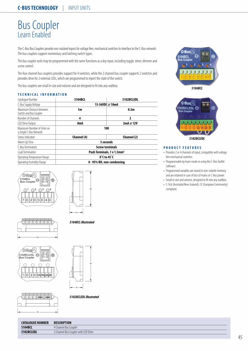
C-Bus TEChnology | Input unIts
45
Bus Coupler5102BCLEDL
1AC2C1
49
18
1K2A2K
55
Bus Coupler5104BCL
C
1
4C3C2C1
2 3 4
55
49
18
Bus CouplerLearn Enabled
the C-Bus Bus Couplers provide non-isolated inputs for voltage free, mechanical switches to interface to the C-Bus network. the bus couplers support momentary and latching switch types.
the bus coupler units may be programmed with the same functions as a key input, including toggle, timer, dimmer and scene control.
the four channel bus couplers provides support for 4 switches, while the 2 channel bus coupler supports 2 switches and provides drive for 2 external LEDs, which are programmed to report the state of the switch.
the bus couplers are small in size and volume and are designed to fit into any wallbox.
T E C h n I C A l I n F o R M A T I o nCatalogue number 5104BCl 5102BClEDlC-Bus supply Voltage 15-36VDC @ 18mAMaximum Distance between 1m 0.3mswitch and Bus Couplernumber of Channels 4 2LED Drive Output 0mA 2mA @ 12VMaximum number of units on 100a single C-Bus networkstatus Indicators Channel (4) Channel (2)Warm up time 5 secondsC-Bus termination screw terminalsLoad termination Push Terminals, 1 x 1.5mm2Operating temperature Range 0˚C to 45˚COperating Humidity Range 0 - 95% Rh, non-condensing
P R o D u C T F E A T u R E s• provides 2 or 4 channels of input, compatible with voltage free mechanical switches.• programmable by learn mode or using the C-Bus toolkit software.• programmed variables are stored in non-volatile memory and are retained in case of loss of mains or C-Bus power.• small in size and volume, designed to fit into any wallbox.• C-tick (Australia/new Zealand), CE (European Community) compliant.
CATAloguE nuMBER DEsCRIPTIon5104BCl 4 Channel Bus Coupler5102BClEDl 2 Channel Bus Coupler with LED Drive
5104BCL
5104BCL illustrated
5102BCLEDL illustrated
5102BCLEDL

C-Bus TEChnology | Input unIts
46
Auxiliary Input unitLearn Enabled
the C-Bus Auxiliary Input unit is a DIn rail mount unit that provides four isolated inputs for voltage free, mechanical switches to interface to the C-Bus network. the auxiliary input supports momentary and latching switch types.
the auxiliary input unit features learn mode, Channel, C-Bus and unit status indicators.
the auxiliary input unit may be programmed with the same functions as a key input, including toggle, timer, dimmer and scene control.
T E C h n I C A l I n F o R M A T I o nCatalogue number l5504AuXC-Bus supply Voltage 15-36VDC @ 18mAswitch Isolation 500VMaximum switch and Cable Impedance 1000Ωswitch Open Voltage 5Vswitch Closed Current 0.4mAMaximum number of units on a 100single C-Bus networkstatus Indicators Channel (4), unit and C-BusWarm up time 5 secondsC-Bus termination 2 x RJ45 socketsLoad termination 2 x 1.5mm2 or 1 x 2.5mm2Operating temperature Range 0˚C to 45˚COperating Humidity Range 0 - 95% Rh, non-condensing
P R o D u C T F E A T u R E s• provides 4 channels of input, compatible with voltage free mechanical switches.• Isolated inputs, up to 500V isolation. • programmable by learn mode or using the C-Bus toolkit software.• programmed variables are stored in non-volatile memory and are retained in case of loss of mains or C-Bus power. • Designed to fit standard 35mm top hat DIn rail, measures just 4M in size.• Designed to fit into standard electrical switchboards. • C-tick (Australia/new Zealand), CE (European Community) compliant.
CATAloguE nuMBER DEsCRIPTIonl5504AuX 4 Channel Auxiliary Input Module
L5504AUX
Auxiliary Input
72
65
32
18
15
456885
C-Bus CONNECTIONS
1B 2B1A 2A 3B 4B3A 4A
1 2 3 4

C-Bus TEChnology | Input unIts
47
pascal Automation Controller
CATAloguE nuMBER DEsCRIPTIon5500PACA C-Bus pascal Automation Controller
the pascal Automation Controller (pAC) is a DIn rail mounted C-Bus device that provides sophisticated and affordable control of a Clipsal C-Bus system. the pAC can perform operations in response to monitored events by executing custom written embedded programs. these programs are written by installers to suit individual application needs using the Microsoft Windows™ based programming Interface for C-Bus Embedded Devices or ‘pICED’ software.
the pAC provides a usB interface through which programs are downloaded. the usB connection can also be used to communicate directly with a C-Bus installation via a pC. this allows the pAC to function as a pC Interface and can be used by the C-Bus toolkit software when configuring a C-Bus installation.
the pAC is a native C-Bus device and is able to interact with the complete range of C-Bus and C-Bus Wireless products.5500PACA
P R o D u C T F E A T u R E s• Conditional and real-time events programming for C-Bus.• Dedicated scheduling, logic and scene programming modules.• Connects and powered from C-Bus.• programmable using the C-Bus toolkit software.• Includes a built-in real time clock.• Compact size, 4M DIn modules wide.• 2 x Rs-232 ports for third party device control.• C-tick (Australia/new Zealand), CE (European Community) compliant.
T E C h n I C A l I n F o R M A T I o nCatalogue number 5500PACAC-Bus supply Voltage 15-36VDC @ 32mABattery Backup supply Voltage 12VDC @ 30mAnetwork Clock software selectablenetwork Burden software selectableMaximum number of C-Bus 10Applications supportedC-Bus Connections 2 x RJ45 socketsRs-232 port Connectors 2 x RJ45Dimensions 72mm(W) x 92mm(h) x 63mm(D)Operating temperature Range 0˚C to 45˚COperating Humidity Range 10 - 95% Rh
72
65
32
18
15
456885
C-Bus
Unit/Comm
Pascal Automation Controller
Status
R
C-Bus CONNECTIONS
User
Indicators
Port 1 Port 2
RS232
BATT-12VDC+
V IN
24VAC
V IN
USB

C-Bus TEChnology | Input unIts
48
Outdoor Motion sensor, 110 Degrees
the C-Bus Outdoor Occupancy sensors are surface mount, input units used to detect movement by sensing natural thermal radiation emitted from any moving body. When movement is detected, the unit issues commands over the C-Bus network to control C-Bus output devices. In addition, the unit features a light level sensor to automatically switch lighting on, under low light conditions.
the sensor has a detection field that covers an area up to 18 metres from the unit, with a field of view of 110 degrees. Advanced microprocessor circuit technology and a flat multi-segmented lens, divide the field of view into 28 zones located at four different levels. this ensures immediate reaction of body movement and reduces the number of ‘ dead zones’ that can be penetrated.
the sensor features learn mode, which permits the unit to be programmed without the need for a pC connected to the system.
the sensor features an environmental rating of Ip66 and is suitable for outdoor applications.
T E C h n I C A l I n F o R M A T I o nCatalogue number 5750WPl E5750WPlBase, Mounting Centres 84mm 60.3mmC-Bus supply Voltage 15-36VDC @ 18mAtimer Range Programmable, 1 sec - 18 hrstimer Resolution 1 secLight threshold Adjustment user adjustable, 1 lux to full sunlightMounting Height 2.4m nominal, (2.0 to 3.2m)Field of View 110 degreesDetection Area 18m radius x 110 degreesLens type Frensel, multi-segmentedMaximum number of units on 100a single C-Bus networkstatus Indicator Walk test lEDWarm up time 5 secondsC-Bus termination Fly lead x 2Ip Rating IP66Operating temperature Range 0˚C to 45˚C
P R o D u C T F E A T u R E s• programmable by learn mode or using the C-Bus toolkit software.• programmed variables are stored in non-volatile memory and are retained in case of loss of mains or C-Bus power.• programmable walk test LED for commissioning.• user adjustable light level threshold, from low light (1 Lux) to full sunlight.• Dual element detectors to minimise false triggering.• Optical bandpass filter minimises unwanted heat sources from triggering the circuitry.• C-tick (Australia/new Zealand), CE (European Community) compliant.
CATAloguE nuMBER DEsCRIPTIonE5750WPl Occupancy sensor, Infared, Ip66, 110 Degrees (British standard)5750WPl Occupancy sensor, Infared, Ip66, 110 Degrees (Australian/us standard)
5750WPL
InFRASCAN
111
20 38
58
138
74
5750WPL illustrated

C-Bus TEChnology | Input unIts
49
Indoor Motion sensor, 90 Degrees
T E C h n I C A l I n F o R M A T I o nCatalogue number 5751l E5751lBase, Mounting Centres 84mm 60.3mmC-Bus supply Voltage 15-36VDC @ 18mAtimer Range Programmable, 1 sec - 18 hrstimer Resolution 1 secLight threshold Adjustment user adjustable, 1 lux to full sunlightMounting Height 2.4m nominal, (2.0 to 3.2m)Field of View 90 degreesDetection Area 6m x 6mMaximum number of units on 100a single C-Bus networkstatus Indicator Walk test lEDWarm up time 5 secondsIp Rating IP44C-Bus termination Fly lead x 2Operating temperature Range 0˚C to 45˚COperating Humidity Range 0 - 95% Rh, non-condensing
P R o D u C T F E A T u R E s • programmable by learn mode or using the C-Bus toolkit software.• programmed variables are stored in non-volatile memory and are retained in case of loss of mains or C-Bus power.• programmable walk test LED for commissioning.• user adjustable light level threshold, from low light (1 Lux) to full sunlight.• Dual element detectors to minimise false triggering.• Optical bandpass filter minimises unwanted heat sources from triggering the circuitry.• C-tick (Australia/new Zealand), CE (European Community) compliant.
CATAloguE nuMBER DEsCRIPTIonE5751l Occupancy sensor, Infrared, 90 Degrees (British standard) with Mounting Base5751l Occupancy sensor, Infrared, 90 Degrees (Australian/us standard) 751MB Mounting Base for 5751L sensor
E5751L
the C-Bus Indoor Occupancy sensors are surface mount, input units used to detect movement by sensing natural thermal radiation emitted from any moving body. When movement is detected, the unit issues commands over the C-Bus network to control C-Bus output devices. In addition, the unit features a light level sensor to automatically switch lighting on, under low light conditions.
the sensor has a detection field that covers an area up to 8.5 metres from the unit, with a field of view of 90 degrees. the unit features a ‘ lens less’ design with 12 overlapping zones forming a continuous detection field. therefore resulting in uniform sensitivity across the whole of the detection field, with no dead zones. this features allows the sensor to be ceiling or wall mounted.
the sensor features learn mode, which permits the unit to be programmed without the need for a pC connected to the system.
the sensor features an environmental rating of Ip44 and is suitable for indoor applications. the sensor is designed for surface mount applications, and located in the corner of the room where detection is required.
-+
-+
VIE
W 108
18
70
R48
90∞ Fieldof View
E5751L illustrated

C-Bus TEChnology | Input unIts
50
Indoor Motion sensor, 360 Degrees
T E C h n I C A l I n F o R M A T I o nCatalogue number 5753lC-Bus supply Voltage 15-36VDC @ 18mAtimer Range Programmable, 1 sec - 18 hrstimer Resolution 1 secLight threshold Adjustment user adjustable, 1 lux to full sunlightMounting Height 2.4m nominal, (2.0 to 3.2m)Field of View 360 degreesDetection Area 12m x 14mMaximum number of units on 100a single C-Bus networkstatus Indicator Walk test lEDWarm up time 5 secondsIp Rating IP44C-Bus termination screw terminalsOperating temperature Range 0˚C to 45˚COperating Humidity Range 0 - 95% Rh, non-condensing
P R o D u C T F E A T u R E s • programmable by learn mode or using the C-Bus toolkit software.• programmed variables are stored in non-volatile memory and are retained in case of loss of mains or C-Bus power.• programmable walk test LED for commissioning.• user adjustable light level threshold, from low light (1 Lux) to full sunlight.• Dual element detectors to minimise false triggering.• Optical bandpass filter minimises unwanted heat sources from triggering the circuitry.• Designed for flush mount applications, protrudes only 8mm. • C-tick (Australia/new Zealand), CE (European Community), FCC (united states) compliant.
CATAloguE nuMBER DEsCRIPTIon 5753l Occupancy sensor, Infrared, Flash Mount, 360 Degrees
5753L
the C-Bus Indoor Occupancy sensors are flush mount, input units used to detect movement by sensing natural thermal radiation emitted from any moving body. When movement is detected, the unit issues commands over the C-Bus network to control C-Bus output devices. In addition, the unit features a light level sensor to automatically switch lighting on, under low light conditions.
the sensor has a detection field that covers an elliptical area up to 12m x 14m, with a field of view of 360 degrees. the unit features a multi-segmented Fresnel lens design, for superior detection capability.
the sensor features learn mode, which permits the unit to be programmed without the need for a pC connected to the system.
the sensor features an environmental rating of Ip44 and is suitable for indoor applications. the sensor is compact in size, and is designed for flush mount applications, located at the centre of the detection area.
Warr
anty
Void
If R
em
oved
47 503672U
nit
Addre
ss
Gro
up
Addre
sses
Netw
ork
12
34
56
MO
D. STATE1036318
88
15
103
R
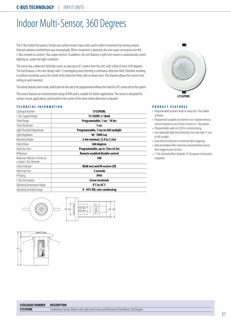
C-Bus TEChnology | Input unIts
51
Indoor Multi-sensor, 360 Degrees
T E C h n I C A l I n F o R M A T I o nCatalogue number 5753PEIRlC-Bus supply Voltage 15-36VDC @ 18mAtimer Range Programmable, 1 sec - 18 hrstimer Resolution 1 secLight threshold Adjustment Programmable, 1 lux to full sunlightLight Regulation 40 - 3000 luxMounting Height 2.4m nominal, (2.0 to 3.2m)Field of View 360 degreesDetection Area Programmable, up to 12m x 8.5mIR Receiver Remote enabled/disable controlMaximum number of units on 100a single C-Bus networkstatus Indicator Walk test and IR receive lEDWarm up time 5 secondsIp Rating IP44C-Bus termination screw terminalsOperating temperature Range 0˚C to 45˚COperating Humidity Range 0 - 95% Rh, non-condensing
P R o D u C T F E A T u R E s• programmable by learn mode or using the C-Bus toolkit software.• programmed variables are stored in non-volatile memory and are retained in case of loss of mains or C-Bus power.• programmable walk test LED for commissioning. • user adjustable light level threshold, from low light (1 Lux) to full sunlight.• Dual element detectors to minimise false triggering. • Optical bandpass filter minimises unwanted heat sources from triggering the circuitry.• C-tick (Australia/new Zealand), CE (European Community) compliant.
CATAloguE nuMBER DEsCRIPTIon5753PEIRl Combination sensor, Motion with Light Level sensor and IR Receiver, Flush Mount, 360 Degrees
5753PEIRL
the C-Bus Indoor Occupancy sensors are surface mount, input units used to detect movement by sensing natural thermal radiation emitted from any moving body. When movement is detected, the unit issues commands over the C-Bus network to control C-Bus output devices. In addition, the unit features a light level sensor to automatically switch lighting on, under low light conditions.
the sensor has a detection field that covers an area up to 8.5 metres from the unit, with a field of view of 90 degrees. the unit features a ‘lens less’ design with 12 overlapping zones forming a continuous detection field. therefore resulting in uniform sensitivity across the whole of the detection field, with no dead zones. this features allows the sensor to be ceiling or wall mounted.
the sensor features learn mode, which permits the unit to be programmed without the need for a pC connected to the system.
the sensor features an environmental rating of Ip44 and is suitable for indoor applications. the sensor is designed for surface mount applications, and located in the corner of the room where detection is required.
Warr
anty
Void
If R
em
oved
47 503672
Unit
Addre
ss
Gro
up
Addre
sses
Netw
ork
12
34
56
MO
D. STATE1036318
88
15
103
R

C-Bus TEChnology | Input unIts
52
Clock Modules
T E C h n I C A l I n F o R M A T I o nC-Bus supply Voltage 15-36VDC @ 18mAtimer 7 daynumber of Channels 2Memory Locations 42Accuracy 2.5 sec/day @ 20˚Ctimer Resolution 1 minuteRunning Reserve 24 hours (without C-Bus power)Reserve Charge time 2 minutesDaylight saving Mode yesRandom Event Generator 5 to 60 minutesDisplay Iconic lCD display, grey scaleMaximum number of units on 100a single C-Bus networkstatus Indicator ProgrammableWarm up time 5 secondsC-Bus termination screw terminalsstandard Colours WE, sg, Ds, CM, BR and BKOperating temperature Range 0˚C to 45˚COperating Humidity Range 0 - 95% Rh, non-condensing
P R o D u C T F E A T u R E s • programmable using the C-Bus toolkit software.• programmed variables are stored in non-volatile memory and are retained in case of loss of mains or C-Bus power.• Reserve power backup in case of loss of C-Bus supply.• C-tick (Australia/new Zealand), CE (European Community) compliant.
CATAloguE nuMBER DEsCRIPTIonAustralian/us standard5031h2TC7 2 Channel Clock, 7 Days, Horizontal Mount 5031V2TC7 2 Channel Clock, 7 Days, Vertical Mount Colour selection: (WE) White, (sg) soft Grey, (Ds) Desert sand, (CM) Cream, (BR) Brown, (BK) Black
British standard E5031/2TC7 2 Channel Clock, 7 Days, Horizontal MountColour selection: (WE) White, (BK) Black
E5031/2TC7, WE
the C-Bus Clock Modules are surface mount, input units used to provide basic timing functions and convenient control of C-Bus output units.
the clock modules are 7-day timers, featuring 42 program storage locations for event programming. Events may be programmed up to 6 days in advance and event durations may be up to 99 days.
Whereas, the clock modules are powered from the two wire C-Bus connection, they feature a rechargeable power storage that maintains the clock for up to 24 hours, in the event of loss of the C-Bus power supply.
the clock modules also feature a daylight saving option and random check generator from 5 to 60 minutes.
72
23
48
76
116
67
87 sq. 23
52
E5031/2TC7illustrated
5031V2TC7, WE
5031V2TC7illustrated

C-Bus TeCHnology | Input unIts
53
temperature sensors
T e C H n I C A l I n F o R M A T I o nC-Bus supply Voltage 15-36VDC @ 18mAAccuracy +/- 1˚CMaximum number of units on 100a single C-Bus network status Indicator ProgrammableWarm up time 5 secondsC-Bus termination screw terminalsstandard Colours We, sg, Ds, CM, BR and BKOperating temperature Range 0˚C to 50˚COperating Humidity Range 0 - 95% RH, non-condensing
P R o D u C T F e A T u R e s• programmable using the C-Bus toolkit software.• programmed variables are stored in non-volatile memory and are retained in case of loss of mains or C-Bus power.• programmable target temperature and Margin.• programmable heating or cooling mode.• C-tick (Australia/new Zealand), CE (European Community) compliant.
CATAlogue nuMBeR DesCRIPTIon Australian/us standard 5031RDTsl We Remote Digital temperature senor-En Colour selection: (We) White, (sg) soft Grey, (Ds) Desert sand, (CM) Cream, (BR) Brown, (BK) Black
British standard e5031RDTsl We Remote Digital temperature senorColour selection: (We) White, (BK) Black
E5031RDTSL WE
the C-Bus temperature sensors are surface mount, input units used to measure ambient temperature and control either cooling mode or heating mode, but not both simultaneously.
the sensor has a range of 0 to 50 degrees Centigrade, with programmable target temperature and margin. In addition, the unit features an economy mode where the target temperature is stepped back. this feature is used to save energy when the room is unoccupied.
the temperature sensor is used in conjunction with C-Bus, interlocked relays to control HVAC equipment.
5031RDTSL WE
72
36
48
116
76
67
87 sq. 36
52
E5031TS illustrated
5031TS illustrated

C-Bus TEChnology | Input unIts
54
T E C h n I C A l I n F o R M A T I o nC-Bus supply Voltage 15-36VDC @ 18mALight Level (measure) 20 - 3000 luxLight Level (regulate) 40 - 1600 luxtime Constant Approx. 90 secondsMounting Height 2.4m nominal, (2.0 to 3.2m)Field of View 180 degreesMaximum number of units on 100a single C-Bus networkstatus Indicator ProgrammableWarm up time 5 secondsC-Bus termination screw terminalsstandard Colours WE, sg, Ds, CM, BR and BKOperating temperature Range 0˚C to 45˚COperating Humidity Range 0 - 95% Rh, non-condensing
Light Level sensors
P R o D u C T F E A T u R E s• programmable using the C-Bus toolkit software.• programmed variables are stored in non-volatile memory and are retained in case of loss of mains or C-Bus power.• programmable target Light Level and Margin.• Bank switching or light level regulation.• C-tick (Australia/new Zealand), CE (European Community) compliant.
CATAloguE nuMBER DEsCRIPTIon Australian/us standard 5031PE Light Level sensor, 40-1600 Lux Colour selection: (WE) White, (sg) soft Grey, (Ds) Desert sand, (CM) Cream, (BR) Brown, (BK) Black
British standard E5031PE Light Level sensor, 40-1600 LuxColour selection: (WE) White, (BK) Black
IP66 Weatherproof seriesE5031PEWP Light Level sensor, 40-1600 Lux, Ip56
E5031PE, WE
the C-Bus Light Level sensors are surface mount input units used to measure ambient light levels and regulate lighting loads.
the sensor has a field of view of 180 degrees, and is capable of measuring lighting levels in the range of 20 to 3000 Lux and regulating lighting in the range of 40 to 1600 Lux, which is suitable for most commercial applications.
the light level sensor may be used in conjunction with non-dimmable ballasts to bank switch luminaires or with dimmable electronic ballasts to regulate lighting levels continuously, within a programmed target range.
the unit features built in lag, to prevent rapid changes in output, due to changes in environmental conditions, such as cloud cover or rapid movement through the detection area.
5031PE, WE
67
87 sq. 23
52
72
23
48
76
116
E5031PE illustrated
5031PE illustrated

C-Bus TEChnology | Input unIts
55
telephone Interface
T E C h n I C A l I n F o R M A T I o nCatalogue numbers 5100TAuC-Bus supply Voltage 15 - 36VDC @ 20mACBtI power supply 12VDC or 15VAC, 50/60hz supplied with Aus 3 pin power pack status Indicators C-Bus, line grab, serial Comms. and Internal Comms.Modes home and AwayC-Bus Connection 2 x RJ45 socketspC Interface Connection DB9 sockettelephone Connection 3 x RJ12 sockets (1 incoming/2 outgoing)Audio Connection 2 RCA sockets (in/out)network Burden software selectablesystem Clock software selectableVoice Library user programmableOperating temperature Range 0˚C to 45˚COperating Humidity Range 0 - 95% Rh, non-condensing
P R o D u C T F E A T u R E s• programmable using the C-Bus telephone Interface configuration software.• programmed variables are stored in non-volatile memory and are retained in case of loss of C-Bus power.• Audio out (line out) to annunciate messages.• Includes user profile number and password to access voice prompt menus.• Remote programming of the C-Bus devices.• supports communication through C-Bus network bridges.• A-tick (Australia/new Zealand), CE (European Community) compliant.
CATAloguE nuMBER DEsCRIPTIon 5100TAu telephone Interface Module, Australian (power pack Included) 5100TMB telephone Mounting Bracket
5100TAU
the C-Bus telephone Interface unit provides a remote telephone interface to the C-Bus network. the dial in, dial out facility permits user to dial in and navigate a voice prompt menu to monitor and control devices on the C-Bus network from a remote location. Control is exercised using the DtMF keypad on the phone.
the telephone interface facilities a connection to the C-Bus network for remote programming of the units using the C-Bus toolkit software.
An audio output is also included so that C-Bus events can be audibly announced. the telephone interface connects to either the public switched telephone network (pstn) or to a local pABX.
the C-Bus telephone Interface unit includes the facility to issue voice prompts, send commands, report status and to obtain operator responses using DtMF tones. the responses are turned into actions on a C-Bus network.
For added security, the telephone interface requires the telephone user to enter a user profile number and password to access the voice prompt menus. upon receipt of the correct password, the unit activates a voice prompt menu and directs the user to available actions or more menus.
the telephone interface incorporates a history log, is supplied pre-loaded with a standard library of words and phrases and supports multiple languages.
RS-232
TELEPHONE INTERFACE
145 sq.C
-BUS
UN
IT CO
MM
S
LINE G
RAB
RS-232 C
OM
MS
C-BUS C-BUS
SECONDARYPHONE-OUT
PRIMARYPHONE-OUT
PHONEIN
12V DC
POWER
AUDIOIN
AUDIOOUT
30
5100TAU illustrated

C-Bus TEChnology | Input unIts
56
universal Remote Control
T E C h n I C A l I n F o R M A T I o nBatteries 4 x AAA Alkaline batteriesBattery Life 3 to 6 monthspower Consumption lCD off : 50µA, lCD on : 300µAOperating Distance Approx. 9mnumber of Devices 16soft Buttons/Device 48 (2 pages of 24)Hard Buttons/Device 7Backlighting Blue lEDLearning Frequency 10 to 455khz and pulseMemory 256KB flash memoryC-Bus IR Codes 5038TX and 5035TXWarm up time 5 secondsOperating temperature Range 0˚C to 45˚C Operating Humidity Range 10 - 95% Rh
P R o D u C T F E A T u R E s• supports up to 16 infrared remote control codes.• Features built-in C-Bus IR codes and menu option.• Large touch screen display and quick control hard buttons.• Audible beep confirmation on button presses.• Battery low warning.• Macro function supports up to 60 codes per macro command.• Learning remote control.• Features pre-programmed codes of popular models of AV equipment.• power save menu for extended battery life.• C-tick (Australia/new Zealand), CE (European Community) compliant.
CATAloguE nuMBER DEsCRIPTIon 5030uRC universal Remote Control with LCD touch screen5030uRCCABlE spL usB programming Cable
5030URC
the 5030uRC is a learning, universal remote control unit that is simple to program and use. By learning the infrared codes of other remote control devices, it allows this single remote control unit to replace all these remote control units, while providing all the same functions.
the universal Remote Control supports up to 16 devices in memory. Devices supported include VCRs, CD players, DVRs, tVs and pay tV Decoders. In addition, the universal remote control features the IR codes for C-Bus devices. this means that this remote control can be used in conjunction with all C-Bus nEO switches, touch screens and scene Controller products.
the universal Remote Control features a touch screen display with backlighting and soft keys for the menu and control options. select from the 16 devices and their corresponding functions and commands at a push of a single button. In addition, the advanced macro function allows a chain of up to 60 commands to be activated with the touch of a single button.
the universal Remote Control provides a complete and centralised infrared remote control solution for control of audio visual and C-Bus devices in one attractive and simple-to-use device.
185
82
AMPC-BUS DISC
AUX
TVSAT/CBL VCR
DVDDATE
POWER
CH CH
VOL
VOL
ENTER
SLEEP
P
30
CH CH
Cable Length: 1500mm
PW
R
TX
D
RX
D
Cable Length: 400mm
5030URC illustrated 5030URCCABLE illustrated
5030URCCABLE

C-Bus TEChnology | Input unIts
57
Monochrome touch screens
P R o D u C T F E A T u R E s• programmable using the C-Bus touch screen configuration software, via the serial connection or over C-Bus.• programmed variables are stored in non-volatile memory and are retained in case of loss of C-Bus power.• powered from the C-Bus, does not require additional power supplies.• supports communication through C-Bus network bridges.• C-tick (Australia/new Zealand), CE (European Community) compliant.
the C-Bus Monochrome touch screen provides elegant interface to the C-Bus control system. the touch screen interface is fully customisable to suit the user’s requirements.
the touch screen supports user defined graphic images, text characters, including Chinese and other languages. the touch screen supports multiple page views, and the interface may be developed to navigate between pages to locate different operating options. the touch screen may be programmed to control lighting, dimming, water sprinklers and curtains.
the touch screen features an embedded scheduler, for event scheduling. In addition, the unit features an infrared receiver for remote activation of functions using a hand held remote control.
the touch screen requires a custom wall box, which is supplied separately.
T E C h n I C A l I n F o R M A T I o nscreen size 119mm(Diagonal) 4.7inches (Diagonal) W100mm x h75mmResolution QVgA (320 pixels x 240 pixels)Control Functions • load switching and dimming • scenes • logic (Versions with logic Engine only) • schedulespower supply Powered directly from C-Bus 15-36V DC @65mA required for normal operation. Does not provide current to the C-Bus network.Maximum number of controlled loads 255 group Addresses on each of 10 C-Bus ApplicationsMaximum number of C-touch units 10on a single C-Bus networkC-Bus Connection loop-in / loop-out Removable Terminal block for C-Busthrid party Interface Rs-232 port (supported by the version with C-Bus logic Engine only)programming port usB Type B (under front fascia)Overall Dimensions Plastic Fascia Version W=193mm h=134mm D=41mm saturn™ Fascia Version W=195mm h=136mm D=47mm neo™ Fascia Version W=192mm h=137mm D=45mm stainless steel Fascia Version W=193mm h=134mm D=45mmOperating temperature Range 10˚C to 45˚COperating Humidity Range 10 - 90% RhFascia styles saturn™, neo™, stainless steel, PlasticAccessories Rs-232 lead (only required for integrating to thrid party devices) Part number 5000CT2Rs232 Wall Box (External Dimensions 179.5mm x 122.5mm x 55mm) Part number 5000CT2WB
SC5000CTL2,WE

C-Bus TEChnology | Input unIts
58
CATAloguE nuMBER DEsCRIPTIon Desktop stand 5000CTD2, WE touch screen, Desktop stand, swivel Base, Grey with stainless steel Fascia, without Logic(White) 5000CTD2, BK touch screen, Desktop stand, swivel Base, Grey with stainless steel Fascia, without Logic(Black) 5000CTD2, gy touch screen, Desktop stand, swivel Base, Grey with stainless steel Fascia, without Logic(Grey) 5000CTDl2, WE touch screen, Desktop stand, swivel Base, Grey with stainless steel Fascia, with Logic(White) 5000CTDl2, BK touch screen, Desktop stand, swivel Base, Grey with stainless steel Fascia, with Logic(Black) 5000CTDl2, gy touch screen, Desktop stand, swivel Base, Grey with stainless steel Fascia, with Logic(Grey)
slimline series sC5000CT2, WE B&W touch screen MKII without Logic Engine (plastic Fascia, White) sC5000CT2, CM B&W touch screen MKII without Logic Engine (plastic Fascia, Cream) sC5000CT2, BK B&W touch screen MKII without Logic Engine (plastic Fascia, Black) sC5000ClT2, WE B&W touch screen MKII with Logic Engine (plastic Fascia, White) sC5000ClT2, CM B&W touch screen MKII with Logic Engine (plastic Fascia, Cream) sC5000ClT2, BK B&W touch screen MKII with Logic Engine (plastic Fascia, Black) sC5000CT2F, WE B&W touch screen MKII Fascia (plastic Fascia, White) sC5000CT2F, CM B&W touch screen MKII Fascia (plastic Fascia, Cream) sC5000CT2F, BK B&W touch screen MKII Fascia (plastic Fascia, Black)
Flat Plate series Bs5000CT2 B&W touch screen MKII without Logic Engine (Metal Fascia, Brushed stainless steel) BB5000CT2 B&W touch screen MKII without Logic Engine (Metal Fascia, polished Brass) Bs5000CTl2 B&W touch screen MKII with Logic Engine (Metal Fascia, Brushed stainless steel) BB5000CTl2 B&W touch screen MKII with Logic Engine (Metal Fascia, polished Brass) Bs5000CT2F B&W touch screen MKII Fascia (Metal Fascia, Brushed stainless steel) BB5000CT2F B&W touch screen MKII Fascia (Metal Fascia, polished Brass)
Accessories 5080CT2,gF B&W touch screen MKII without Logic Engine (saturn style Fascia, White) 5080CT2-3 B&W touch screen MKII without Logic Engine (saturn style Fascia, Cream) 5080CT2-7 B&W touch screen MKII without Logic Engine (saturn style Fascia, Mid Brown) 5080CT2-6 B&W touch screen MKII without Logic Engine (saturn style Fascia, Black) 5080CTl2,gF B&W touch screen MKII with Logic Engine (saturn style Fascia, White) 5080CTl2-3 B&W touch screen MKII with Logic Engine (saturn style Fascia, Cream) 5080CTl2-7 B&W touch screen MKII with Logic Engine (saturn style Fascia, Mid Brown) 5080CTl2-6 B&W touch screen MKII with Logic Engine (saturn style Fascia, Black) 5080CT2F,gF B&W touch screen MKII Fascia (saturn style Fascia, White) 5080CT2F-3 B&W touch screen MKII Fascia (saturn style Fascia, Cream) 5080CT2F-7 B&W touch screen MKII Fascia (saturn style Fascia, Mid Brown) 5080CT2F-6 B&W touch screen MKII Fascia (saturn style Fascia, Black)
5050CT2,gB B&W touch screen MKII without Logic Engine (neo style Fascia, Gray & Brushed Aluminium) 5050CT2,WE B&W touch screen MKII without Logic Engine (neo style Fascia, White) 5050CT2-28 B&W touch screen MKII without Logic Engine (neo style Fascia, White & Brushed Aluminium) 5050CT2,BK B&W touch screen MKII without Logic Engine (neo style Fascia, Black)

C-Bus TEChnology | Input unIts
59
5080CTC2, GF
5050CTC2, 28
Colour touch screens
the C-Bus Colour touch screen provides a simple, elegant and functional interface to the C-Bus management and control system. the touch screen provides a focal point to control and monitor the building’s electrical systems, such as lighting, irrigation and entertainment services.
the touch screen is a wall mounted, touch sensitive, high resolution LCD screen that supports user defined graphics such as sliders, bitmaps and images and text characters, including English, Chinese, Arabic and other languages. the menus are fully customised at the time of installation, and may be changed at any time thereafter.
the touch screen incorporates an astronomical, real time clock for event scheduling and calendar functions, based on time of day, week, month or year. the colour touch screen features a logic engine module, that facilitates the development of logic based routines and scenarios, providing additional functionality of the installed system.
In addition, the colour touch screen is supplied with powerful configuration software that allows the installer to develop custom pages and menus to suit any installation of any size.
Available in either nEO or uLtI style, to complement the existing C-Bus wall switches. In addition, the touch screen features backlighting, that is controlled from a light level sensor located on the unit. the touch screen requires a custom wall box, which is supplied separately.
P R o D u C T F E A T u R E s• programmable using the C-Bus touch screen configuration software, via the serial or Ethernet connection.• programmed variables are stored in non-volatile memory and are retained in case of loss of C-Bus power.• Controls and monitors devices connected to the C-Bus, Ethernet or serial connections.• Functions include; scheduling, scene control, irrigation control, logic and scenario management.• Astronomical clock for scheduling and time management of events.• Graphical user based drag and drop configuration software, plus free form logic programming language.• software interface design supports 101 levels of alpha blending.• Animated buttons with up to 256 animation frames supported.• Fully customized graphics, including bar graphs, sliders, percentage indicators, images, gauges and clocks, with any border and background style.• supports embedded web pages.• supports audio WAV files.• password access control.• External power supply included.• C-tick (Australia/new Zealand), CE (European Community) compliant.
T E C h n I C A l I n F o R M A T I o nC-Bus supply Voltage 15 - 36VDC @ 22mA External power supply 5VDC @ 10A (supplied) Control Functions switching, dimming, scene control, event scheduling or logic module screen type lCD active matrix, backlit touch Overlay type Resistive membrane Resolution VgA, 640 x 480 pixels screen size 16.25cm (diagonal) screen Viewing Area 130mm(W) x 97mm(h) Horizontal Viewing Angles +/- 70˚ Vertical Viewing Angles 40˚ up and 70˚ down Luminance 300 cd/m2 Backlight Cold cathode with light sensor Memory 256MB compact flash Real time Clock 365 day Warm up time 60 seconds network Burden software selectable system Clock software selectable C-Bus Connection 2 x RJ45 sockets Ethernet Connection 2 x RJ45 sockets, 10/100Mhz serial Connection DB9 plug Composite Video RCA socket styles nEo (ABs), ulTI (glass), Brass and stainless steelDimensions 248mm(W) x 175mm(h) x 60mm(D) Operating temperature Range 0˚C to 30˚C Operating Humidity Range 10 - 95% Rh, non-condensing
cont’d next page

C-Bus TEChnology | Input unIts
60
CaTaloguE numBEr DEsCripTionulTi Family 5080CTC2 touch screen, Colour, Less Wall Box and power supply, Glass Fascia Colour selection: (gF) White, (3) Cream, (6) Black, (7) Mid-BrownnEo Family 5050CTC2 touch screen, Colour, Less Wall Box and power supply Colour selection: (28) White Aluminium, (BK) Black, (gB) Grey Aluminium, (WE) WhiteFlat plate series Bs5000CTC/2 touch screen, Colour, Less Wall Box and power supply, stainless steel
Accessories for Colour touch screen
CaTaloguE numBEr DEsCripTionWall Box and nail Bracket 5000CT2 Wall Box for BW touch screen MKII 5000CTC power supply, 5VDC @ 10Apower supply 5000CT2,WE nail Bracket for Colour touch screen MKIIFascia 5080CT2F Fascia, Glass Colour selection: (gF) White, (3) Cream, (6) Black, (7) Mid-Brown 5050CT2F Fascia, nEO Colour selection: (28) White & Brushed Aluminium, (BK) Black, (gB) Grey & Brushed Aluminium, (WE) White
24814
71
175 148
202
246
173157
202
199
150
19
54
78
178
256
5
Colour touch screens
5080CTC illustrated
5050CTC illustrated
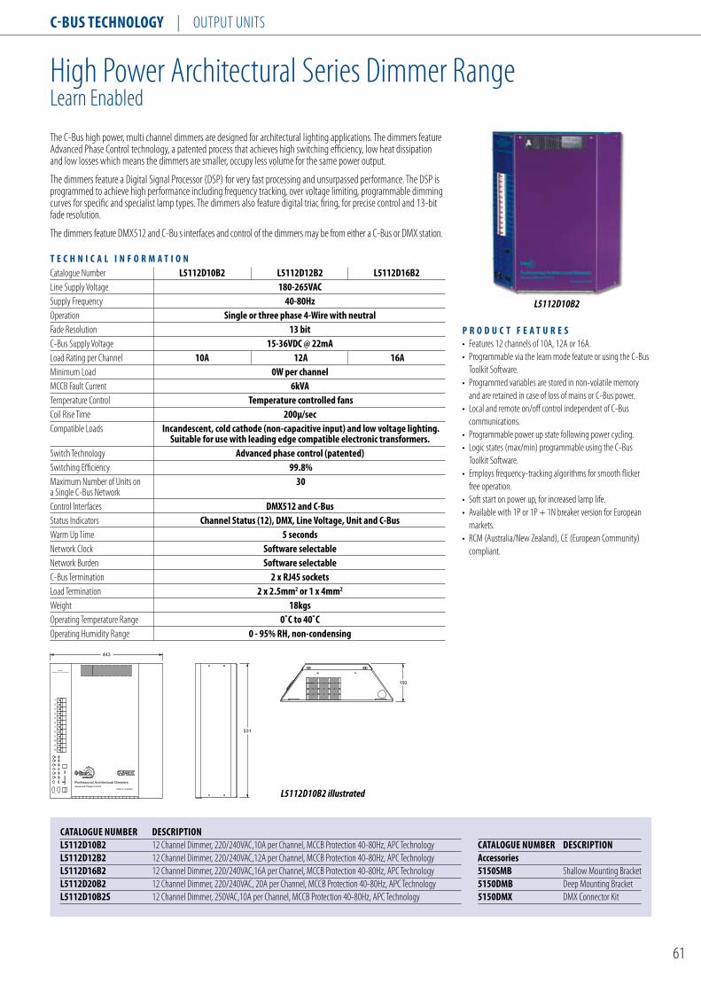
C-Bus TEChnology | Output unIts
61
High power Architectural series Dimmer RangeLearn Enabled
the C-Bus high power, multi channel dimmers are designed for architectural lighting applications. the dimmers feature Advanced phase Control technology, a patented process that achieves high switching efficiency, low heat dissipation and low losses which means the dimmers are smaller, occupy less volume for the same power output.
the dimmers feature a Digital signal processor (Dsp) for very fast processing and unsurpassed performance. the Dsp is programmed to achieve high performance including frequency tracking, over voltage limiting, programmable dimming curves for specific and specialist lamp types. the dimmers also feature digital triac firing, for precise control and 13-bit fade resolution.
the dimmers feature DMX512 and C-Bu s interfaces and control of the dimmers may be from either a C-Bus or DMX station.
T E C h n I C A l I n F o R M A T I o nCatalogue number l5112D10B2 l5112D12B2 l5112D16B2Line supply Voltage 180-265VACsupply Frequency 40-80hzOperation single or three phase 4-Wire with neutralFade Resolution 13 bitC-Bus supply Voltage 15-36VDC @ 22mALoad Rating per Channel 10A 12A 16AMinimum Load 0W per channelMCCB Fault Current 6kVAtemperature Control Temperature controlled fansCoil Rise time 200µ/secCompatible Loads Incandescent, cold cathode (non-capacitive input) and low voltage lighting. suitable for use with leading edge compatible electronic transformers.switch technology Advanced phase control (patented)switching Efficiency 99.8%Maximum number of units on 30a single C-Bus network Control Interfaces DMX512 and C-Busstatus Indicators Channel status (12), DMX, line Voltage, unit and C-BusWarm up time 5 secondsnetwork Clock software selectablenetwork Burden software selectableC-Bus termination 2 x RJ45 socketsLoad termination 2 x 2.5mm2 or 1 x 4mm2
Weight 18kgsOperating temperature Range 0˚C to 40˚COperating Humidity Range 0 - 95% Rh, non-condensing
P R o D u C T F E A T u R E s • Features 12 channels of 10A, 12A or 16A.• programmable via the learn mode feature or using the C-Bus toolkit software.• programmed variables are stored in non-volatile memory and are retained in case of loss of mains or C-Bus power.• Local and remote on/off control independent of C-Bus communications.• programmable power up state following power cycling.• Logic states (max/min) programmable using the C-Bus toolkit software.• Employs frequency-tracking algorithms for smooth flicker free operation.• soft start on power up, for increased lamp life.• Available with 1p or 1p + 1n breaker version for European markets.• RCM (Australia/new Zealand), CE (European Community) compliant.
L5112D10B2
CATAloguE nuMBER DEsCRIPTIonl5112D10B2 12 Channel Dimmer, 220/240VAC,10A per Channel, MCCB protection 40-80Hz, ApC technologyl5112D12B2 12 Channel Dimmer, 220/240VAC,12A per Channel, MCCB protection 40-80Hz, ApC technologyl5112D16B2 12 Channel Dimmer, 220/240VAC,16A per Channel, MCCB protection 40-80Hz, ApC technologyl5112D20B2 12 Channel Dimmer, 220/240VAC, 20A per Channel, MCCB protection 40-80Hz, ApC technologyl5112D10B2s 12 Channel Dimmer, 250VAC,10A per Channel, MCCB protection 40-80Hz, ApC technology
CATAloguE nuMBER DEsCRIPTIonAccessories5150sMB shallow Mounting Bracket5150DMB Deep Mounting Bracket5150DMX DMX Connector Kit
531
443
150
1
2
3
4
5
6
7
8
9
10
12
11
WARNING
DANGER HIGH VOLTAGE INSIDE
Made in AustraliaAdvanced Phase Control
Professional Architectural Dimmers
531
443
150
1
2
3
4
5
6
7
8
9
10
12
11
WARNING
DANGER HIGH VOLTAGE INSIDE
Made in AustraliaAdvanced Phase Control
Professional Architectural Dimmers
L5112D10B2 illustrated

C-Bus TEChnology | Output unIts
62
12 Channel professional Dimmers
the C-Bus L5112D range of professional dimmers are high powered 12 channel dimmers designed for commercial applications such as hotels, restaurants and office buildings.
the unit is a C-Bus controlled, high power, multi phase control dimmer, which is compatible with a wide range of load types, including neon. Leading and trailing edge models are available.
Dimming is achieved through phase control techniques creating a highly efficient range of dimmers.
Channel de-rating for use with electronic transformer loads is not required. Each channel is capable of supporting full load current.
the L5112D range of professional dimmers provide on-board MCB protection, thermal overload protection.
the dimmer range contains modular output channel cards of various ratings with both leading and trailing edge technology, providing ability to customize the dimmer to site needs.
A maintained active output is provided on each channel for emergency lighting.
Each channel card has a bypass switch which permits direct local override of the lighting circuit.
In the event of an over-temperature condition, for example, one caused by excessive load current being drawn, the dimmer channel reduces the output power as long as the condition exists.
the professional dimmer is designed and tested for a wide range of international markets with comprehensive EMC and electrical safety testing and is fully ROHs compliant.
P R o D u C T F E A T u R E s• soft start load turn-on protects lamp filaments. • Voltage compensation to minimize load brightness variation
if the AC supply voltage drifts. • Mounting brackets included for ease of installation. • suitable for single or three phase track lighting applications
with optional 3 phase MCB’s.• Filtering to reduce supply voltage signalling effects. • After mains fail, dimmer returns to previous or preset values. • Linear output load power following input control. • C-Bus network burden and network clock generator. • Emergency lighting output for each channel. • On-board MCB. • Fan free operation, reduces maintenance requirements. • Manual dimmer bypass switch on all channels. • Local C-Bus override switches on front panel. • Generous mains supply terminals and load terminals. • Channel status indicators on front control panel. • Complies with International standards for light dimmers as
below.
Directive standard Title
EMC Directive 2004/108/EC En 60669-2-1 Clause 26.1 RF and Low Frequency Emissions
En 60669-2-1 Clause 26.2 Immunity to EsD, RFI, EFt, surge Voltages, Voltage Dips and Interruptions
En 55014-1 * Electromagnetic compatibility – Requirements for household appliances, electric tools and similar apparatus - Emission
En 55015 * Limits and methods of measurement of radio disturbance charac-teristics of electrical lighting and similar equipment
En 61000-3-2 Electromagnetic compatibility (EMC) – part 3-2: Limits for harmonic current emissions (equipment input current up to and including 16A per phase)
En 61000-3-3 Electromagnetic compatibility (EMC) – part 3-3: Limits – Limita-tion of voltage changes, voltage fluctuations and flicker in public low-voltage systems, for equipment with rated current less or equal to 16A per phase and not subject to conditional connection
En 61000-3-5 * Electromagnetic compatibility (EMC) – part 3-5: Limits – Limita-tion of voltage fluctuations and flicker in low-voltage power supply systems for equipment with rated current greater than 16A
En 61000-3-11 * Electromagnetic compatibility (EMC) – part 3-11: Limits – Limitation of Voltage Changes, Voltage Fluctuations and Flicker in public Low-voltage supply systems, for equipment with rated current less than 75A subject to conditional connection
Low Voltage Directive 2006/95/EC
En 60439-1 Low-voltage switchgear and control gear assemblies. part 1: type-tested and partially type-tested assemblies
En 60669-2-1 switches for household and similar fixed electrical installations – part 2: particular requirements – section 1: Electronic switches
Electrical safety En 60439-1 Low-voltage switchgear and control gear assemblies. part 1: type-tested and partially type-tested assemblies
En 60669-2-1 switches for household and similar fixed electrical installations – part 2: particular requirements – section 1: Electronic switches
RoHs Directive 2002/95/EC - Restriction of Hazardous substances
L5112D10TP
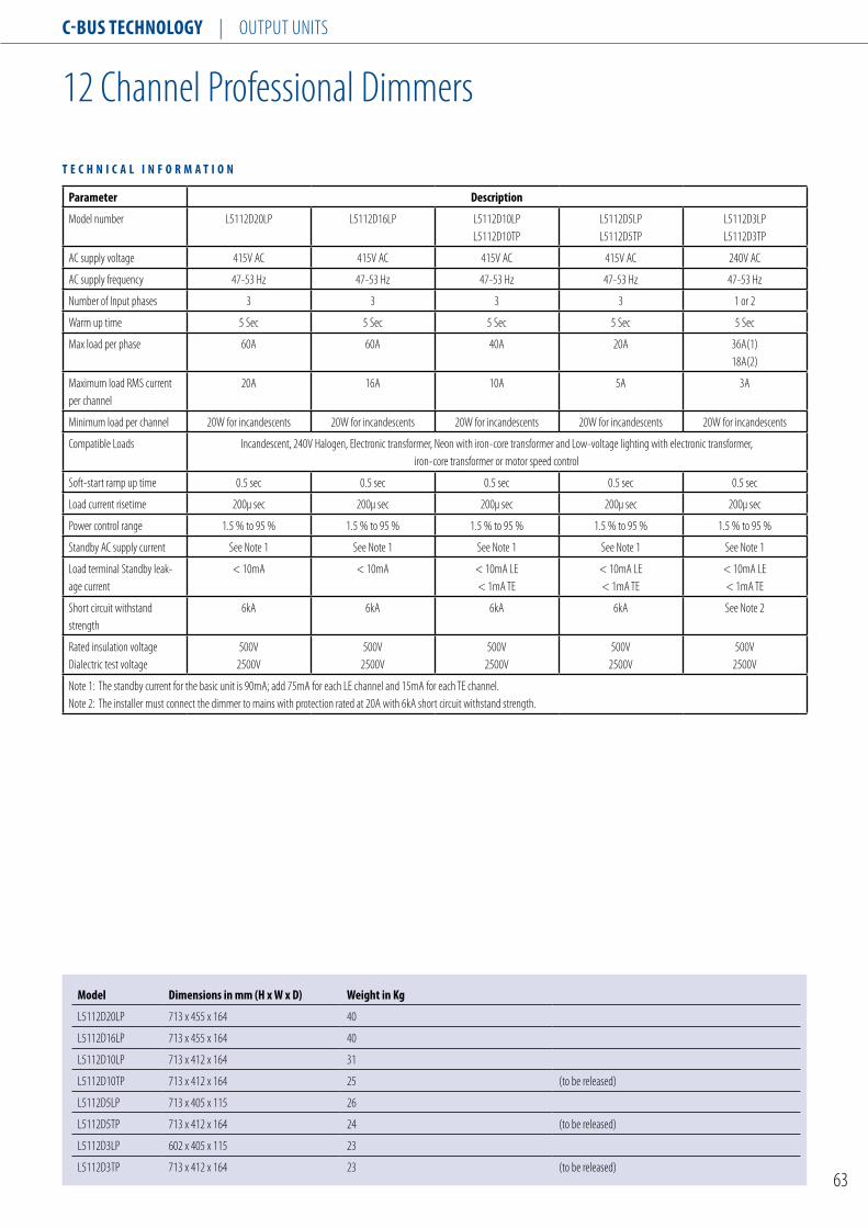
C-Bus TEChnology | Output unIts
63
12 Channel professional Dimmers
Parameter Description
Model number L5112D20Lp L5112D16Lp L5112D10LpL5112D10tp
L5112D5LpL5112D5tp
L5112D3LpL5112D3tp
AC supply voltage 415V AC 415V AC 415V AC 415V AC 240V AC
AC supply frequency 47-53 Hz 47-53 Hz 47-53 Hz 47-53 Hz 47-53 Hz
number of Input phases 3 3 3 3 1 or 2
Warm up time 5 sec 5 sec 5 sec 5 sec 5 sec
Max load per phase 60A 60A 40A 20A 36A(1)18A(2)
Maximum load RMs current per channel
20A 16A 10A 5A 3A
Minimum load per channel 20W for incandescents 20W for incandescents 20W for incandescents 20W for incandescents 20W for incandescents
Compatible Loads Incandescent, 240V Halogen, Electronic transformer, neon with iron-core transformer and Low-voltage lighting with electronic transformer, iron-core transformer or motor speed control
soft-start ramp up time 0.5 sec 0.5 sec 0.5 sec 0.5 sec 0.5 sec
Load current risetime 200μ sec 200μ sec 200μ sec 200μ sec 200μ sec
power control range 1.5 % to 95 % 1.5 % to 95 % 1.5 % to 95 % 1.5 % to 95 % 1.5 % to 95 %
standby AC supply current see note 1 see note 1 see note 1 see note 1 see note 1
Load terminal standby leak-age current
< 10mA < 10mA < 10mA LE< 1mA tE
< 10mA LE< 1mA tE
< 10mA LE< 1mA tE
short circuit withstand strength
6kA 6kA 6kA 6kA see note 2
Rated insulation voltageDialectric test voltage
500V2500V
500V2500V
500V2500V
500V2500V
500V2500V
note 1: the standby current for the basic unit is 90mA; add 75mA for each LE channel and 15mA for each tE channel.note 2: the installer must connect the dimmer to mains with protection rated at 20A with 6kA short circuit withstand strength.
T E C h n I C A l I n F o R M A T I o n
Model Dimensions in mm (h x W x D) Weight in Kg
L5112D20Lp 713 x 455 x 164 40
L5112D16Lp 713 x 455 x 164 40
L5112D10Lp 713 x 412 x 164 31
L5112D10tp 713 x 412 x 164 25 (to be released)
L5112D5Lp 713 x 405 x 115 26
L5112D5tp 713 x 412 x 164 24 (to be released)
L5112D3Lp 602 x 405 x 115 23
L5112D3tp 713 x 412 x 164 23 (to be released)
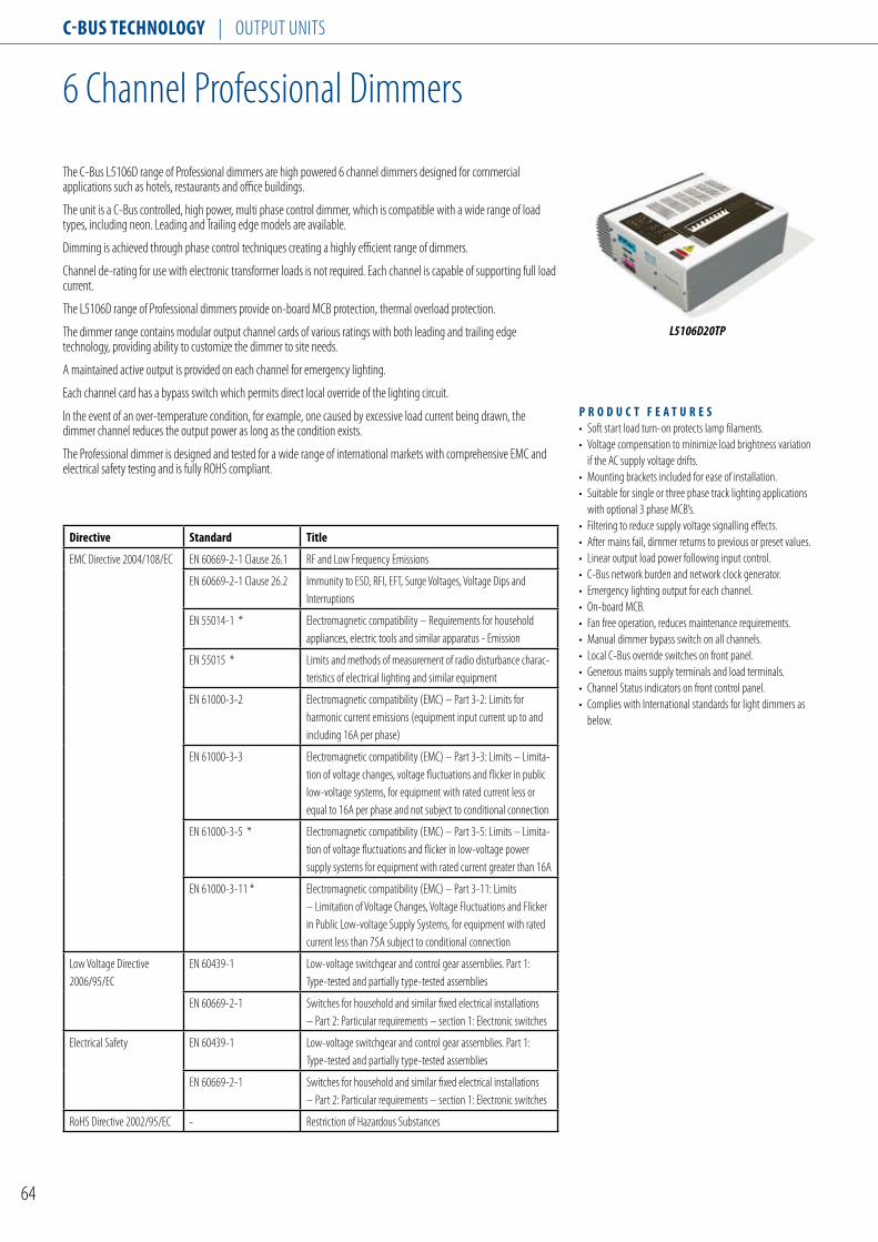
C-Bus TEChnology | Output unIts
64
6 Channel professional Dimmers
the C-Bus L5106D range of professional dimmers are high powered 6 channel dimmers designed for commercial applications such as hotels, restaurants and office buildings.
the unit is a C-Bus controlled, high power, multi phase control dimmer, which is compatible with a wide range of load types, including neon. Leading and trailing edge models are available.
Dimming is achieved through phase control techniques creating a highly efficient range of dimmers.
Channel de-rating for use with electronic transformer loads is not required. Each channel is capable of supporting full load current.
the L5106D range of professional dimmers provide on-board MCB protection, thermal overload protection.
the dimmer range contains modular output channel cards of various ratings with both leading and trailing edge technology, providing ability to customize the dimmer to site needs.
A maintained active output is provided on each channel for emergency lighting.
Each channel card has a bypass switch which permits direct local override of the lighting circuit.
In the event of an over-temperature condition, for example, one caused by excessive load current being drawn, the dimmer channel reduces the output power as long as the condition exists.
the professional dimmer is designed and tested for a wide range of international markets with comprehensive EMC and electrical safety testing and is fully ROHs compliant.
P R o D u C T F E A T u R E s• soft start load turn-on protects lamp filaments. • Voltage compensation to minimize load brightness variation
if the AC supply voltage drifts. • Mounting brackets included for ease of installation. • suitable for single or three phase track lighting applications
with optional 3 phase MCB’s.• Filtering to reduce supply voltage signalling effects. • After mains fail, dimmer returns to previous or preset values. • Linear output load power following input control. • C-Bus network burden and network clock generator. • Emergency lighting output for each channel. • On-board MCB. • Fan free operation, reduces maintenance requirements. • Manual dimmer bypass switch on all channels. • Local C-Bus override switches on front panel. • Generous mains supply terminals and load terminals. • Channel status indicators on front control panel. • Complies with International standards for light dimmers as
below.
Directive standard Title
EMC Directive 2004/108/EC En 60669-2-1 Clause 26.1 RF and Low Frequency Emissions
En 60669-2-1 Clause 26.2 Immunity to EsD, RFI, EFt, surge Voltages, Voltage Dips and Interruptions
En 55014-1 * Electromagnetic compatibility – Requirements for household appliances, electric tools and similar apparatus - Emission
En 55015 * Limits and methods of measurement of radio disturbance charac-teristics of electrical lighting and similar equipment
En 61000-3-2 Electromagnetic compatibility (EMC) – part 3-2: Limits for harmonic current emissions (equipment input current up to and including 16A per phase)
En 61000-3-3 Electromagnetic compatibility (EMC) – part 3-3: Limits – Limita-tion of voltage changes, voltage fluctuations and flicker in public low-voltage systems, for equipment with rated current less or equal to 16A per phase and not subject to conditional connection
En 61000-3-5 * Electromagnetic compatibility (EMC) – part 3-5: Limits – Limita-tion of voltage fluctuations and flicker in low-voltage power supply systems for equipment with rated current greater than 16A
En 61000-3-11 * Electromagnetic compatibility (EMC) – part 3-11: Limits – Limitation of Voltage Changes, Voltage Fluctuations and Flicker in public Low-voltage supply systems, for equipment with rated current less than 75A subject to conditional connection
Low Voltage Directive 2006/95/EC
En 60439-1 Low-voltage switchgear and control gear assemblies. part 1: type-tested and partially type-tested assemblies
En 60669-2-1 switches for household and similar fixed electrical installations – part 2: particular requirements – section 1: Electronic switches
Electrical safety En 60439-1 Low-voltage switchgear and control gear assemblies. part 1: type-tested and partially type-tested assemblies
En 60669-2-1 switches for household and similar fixed electrical installations – part 2: particular requirements – section 1: Electronic switches
RoHs Directive 2002/95/EC - Restriction of Hazardous substances
L5106D20TP

C-Bus TEChnology | Output unIts
65
6 Channel professional Dimmers
Parameter Description
Model number L5106D20LpL5106D20tp
L5106D16tp L5106D10LpL5106D10tp
L5106D5LpL5106D5tp
L5106D3LpL5106D3tp
AC supply voltage 415V AC 415V AC 415V AC 415V AC 240V AC
AC supply frequency 47-53 Hz 47-53 Hz 47-53 Hz 47-53 Hz 47-53 Hz
number of Input phases 3 3 3 3 1
Warm up time 5 sec 5 sec 5 sec 5 sec 5 sec
Max load per phase 40A 40A 20A 30A 20A
Maximum load RMs current per channel
20A 16A 10A 5A 3A
Minimum load per channel 20W for incandescents 20W for incandescents 20W for incandescents 20W for incandescents 20W for incandescents
Compatible Loads Incandescent, 240V Halogen, Electronic transformer, neon with iron-core transformer and Low-voltage lighting with electronic transformer, iron-core transformer or motor speed control
soft-start ramp up time 0.5 sec 0.5 sec 0.5 sec 0.5 sec 0.5 sec
Load current risetime 200μ sec 200μ sec 200μ sec 200μ sec 200μ sec
power control range 1.5 % to 95 % 1.5 % to 95 % 1.5 % to 95 % 1.5 % to 95 % 1.5 % to 95 %
standby AC supply current see note 1 see note 1 see note 1 see note 1 see note 1
Load terminal standby leak-age current
< 10mA LE< 1mA tE
< 10mA < 10mA LE< 1mA tE
< 10mA LE< 1mA tE
< 10mA LE< 1mA tE
short circuit withstand strength
6kA 6kA 6kA 6kA see note 2
Rated insulation voltageDialectric test voltage
500V2500V
500V2500V
500V2500V
500V2500V
500V2500V
note 1: the standby current for the basic unit is 90mA; add 75mA for each LE channel and 15mA for each tE channel.note 2: the installer must connect the dimmer to mains with protection rated at 20A with 6kA short circuit withstand strength.
T E C h n I C A l I n F o R M A T I o n
Model Dimensions in mm (h x W x D) Weight in Kg
L5106D20Lp 451 x 455 x 164 27
L5106D20tp 713 x 455 x 164 18 (to be released)
L5106D16tp 713 x 455 x 164 18 (to be released)
L5106D10Lp 451 x 412 x 164 21
L5106D10tp 451 x 455 x 164 20 (to be released)
L5106D5Lp 451 x 405 x 115 18
L5106D5tp 451 x 412 x 164 18 (to be released)
L5106D3Lp 451 x 405 x 115 16
L5106D3tp 451 x 412 x 164 17 (to be released)

C-Bus TEChnology | Output unIts
66
3 Channel professional Dimmers
the C-Bus L5103D range of professional dimmers are high powered 3 channel dimmers designed for commercial applications such as hotels, restaurants and office buildings.
the unit is a C-Bus controlled, high power, multi phase control dimmer, which is compatible with a wide range of load types, including neon. Leading and trailing edge models are available.
Dimming is achieved through phase control techniques creating a highly efficient range of dimmers.
Channel de-rating for use with electronic transformer loads is not required. Each channel is capable of supporting full load current.
the L5103D range of professional dimmers provide on-board MCB protection, thermal overload protection.
the dimmer range contains modular output channel cards of various ratings with both leading and trailing edge technology, providing ability to customize the dimmer to site needs.
A maintained active output is provided on each channel for emergency lighting.
Each channel card has a bypass switch which permits direct local override of the lighting circuit.
In the event of an over-temperature condition, for example, one caused by excessive load current being drawn, the dimmer channel reduces the output power as long as the condition exists.
the professional dimmer is designed and tested for a wide range of international markets with comprehensive EMC and electrical safety testing and is fully ROHs compliant.
P R o D u C T F E A T u R E s• soft start load turn-on protects lamp filaments. • Voltage compensation to minimize load brightness variation
if the AC supply voltage drifts. • Mounting brackets included for ease of installation. • suitable for single or three phase track lighting applications
with optional 3 phase MCB’s.• Filtering to reduce supply voltage signalling effects. • After mains fail, dimmer returns to previous or preset values. • Linear output load power following input control. • C-Bus network burden and network clock generator. • Emergency lighting output for each channel. • On-board MCB. • Fan free operation, reduces maintenance requirements. • Manual dimmer bypass switch on all channels. • Local C-Bus override switches on front panel. • Generous mains supply terminals and load terminals. • Channel status indicators on front control panel. • Complies with International standards for light dimmers as
below.
Directive standard Title
EMC Directive 2004/108/EC En 60669-2-1 Clause 26.1 RF and Low Frequency Emissions
En 60669-2-1 Clause 26.2 Immunity to EsD, RFI, EFt, surge Voltages, Voltage Dips and Interruptions
En 55014-1 * Electromagnetic compatibility – Requirements for household appliances, electric tools and similar apparatus - Emission
En 55015 * Limits and methods of measurement of radio disturbance charac-teristics of electrical lighting and similar equipment
En 61000-3-2 Electromagnetic compatibility (EMC) – part 3-2: Limits for harmonic current emissions (equipment input current up to and including 16A per phase)
En 61000-3-3 Electromagnetic compatibility (EMC) – part 3-3: Limits – Limita-tion of voltage changes, voltage fluctuations and flicker in public low-voltage systems, for equipment with rated current less or equal to 16A per phase and not subject to conditional connection
En 61000-3-5 * Electromagnetic compatibility (EMC) – part 3-5: Limits – Limita-tion of voltage fluctuations and flicker in low-voltage power supply systems for equipment with rated current greater than 16A
En 61000-3-11 * Electromagnetic compatibility (EMC) – part 3-11: Limits – Limitation of Voltage Changes, Voltage Fluctuations and Flicker in public Low-voltage supply systems, for equipment with rated current less than 75A subject to conditional connection
Low Voltage Directive 2006/95/EC
En 60439-1 Low-voltage switchgear and control gear assemblies. part 1: type-tested and partially type-tested assemblies
En 60669-2-1 switches for household and similar fixed electrical installations – part 2: particular requirements – section 1: Electronic switches
Electrical safety En 60439-1 Low-voltage switchgear and control gear assemblies. part 1: type-tested and partially type-tested assemblies
En 60669-2-1 switches for household and similar fixed electrical installations – part 2: particular requirements – section 1: Electronic switches
RoHs Directive 2002/95/EC - Restriction of Hazardous substances
L5103D20TP

C-Bus TEChnology | Output unIts
67
3 Channel professional Dimmers
Parameter Description
Model number L5103D20LpL5103D20tp
L5103D10tpL5103D10tp
L5103D5LpL5103D5tp
AC supply voltage 415V AC 415V AC 240V AC
AC supply frequency 47-53 Hz 47-53 Hz 47-53 Hz
number of Input phases 3 3 1
Warm up time 5 sec 5 sec 5 sec
Max load per phase 20A 30A 1 phase10A 3 phase
15A
Maximum load RMs current per channel
20A 10A 5A
Minimum load per channel 20W for incandescents 20W for incandescents 20W for incandescents
Compatible Loads Incandescent, 240V Halogen, Electronic transformer, neon with iron-core transformer and Low-voltage lighting with electronic transformer, iron-core transformer or motor speed control
soft-start ramp up time 0.5 sec 0.5 sec 0.5 sec
Load current risetime 200μ sec 200μ sec 200μ sec
power control range 1.5 % to 95 % 1.5 % to 95 % 1.5 % to 95 %
standby AC supply current see note 1 see note 1 see note 1
Load terminal standby leakage current
< 10mA LE< 1mA tE
< 10mA LE< 1mA tE
< 10mA LE< 1mA tE
short circuit withstand strength
6kA 6kA 6kA
Rated insulation voltageDialectric test voltage
500V2500V
500V2500V
500V2500V
note 1: the standby current for the basic unit is 90mA; add 75mA for each LE channel and 15mA for each tE channel.note 2: the installer must connect the dimmer to mains with protection rated at 20A with 6kA short circuit withstand strength.
T E C h n I C A l I n F o R M A T I o n
Model Dimensions in mm (h x W x D) Weight in Kg
L5103D20Lp 289 x 455 x 164 15
L5103D20tp 451 x 455 x 164 15 (to be released)
L5103D10Lp 289 x 412 x 164 12
L5103D10tp 289 x 455 x 164 10 (to be released)
L5103D5Lp 289 x 405 x 115 10
L5103D5tp 289 x 412 x 164 10 (to be released)

C-Bus TEChnology | Output unIts
68
4 Channel Dimmer RangeLearn Enabled
the C-Bus 4 Channel Dimmer units are DIn rail mount units employing leading edge phase control circuitry for dimming control. these dimmer units feature learn mode, local and remote overrides for on/off control, Channel, C-Bus and unit status indicators.
Each dimmer channel is rated at 2 Amps and is suitable for incandescent and low voltage lighting using magnetic and leading edge compatible transformers. the dimmer output is controllable over the range of 2-98%, while frequency tracking algorithms ensure flicker-free operation and smooth dimming control.
the dimmer units are available as passive and current sourcing models that source up to 200mA to the C-Bus network.
T E C h n I C A l I n F o R M A T I o nCatalogue number l5504D2A l5504D2AP lE5504TD2A lE5504TD2AP l5504D2u l5504D2uP Line supply Voltage 220-240VAC 110-120VAC 220 - 240VACsupply Frequency 47-53hz and 57-63hz 47 - 53hzFrequency Drift 3hz/minute (maximum) /Frequency step Change 0.1hz (maximum) /C-Bus supply Voltage 15-36VDC @ 0mA 15-36VDC @ 18mALoad Rating per Channel 2A 2AMinimum Load 15W per channel 20W per channel 12W per channelControl Range 2 - 98% /Compatible Loads Incandescent and low voltage lighting. suitable for use with leading edge compatible electronic transformers.C-Bus source Current 200mA 0mA 200mA 0mA 200mA 0mAMaximum number of units on 10 100 10 100 10 100a single C-Bus networkstatus Indicators Channel status (4), unit and C-BusWarm up time 5 secondsnetwork Clock software selectablenetwork Burden software selectableC-Bus termination 2 x RJ45 socketLoad termination 2 x 1.5mm2 or 1 x 2.5mm2
Operating temperature Range 0˚C to 45˚COperating Humidity Range 0 - 95% Rh, non-condensing 10 - 95% Rh
CATAloguE nuMBER DEsCRIPTIonl5504D2A 4 Channel Dimmer, 2A per Channel, 220/240VAC, 50/60Hz, C-Bus 200mAl5504D2AP 4 Channel Dimmer, 2A per Channel, 220/240VAC, 50/60HzlE5504TD2A 4 Channel Dimmer, 2A per Channel, 110/120VAC, 50/60Hz, C-Bus 200mAlE5504TD2AP 4 Channel Dimmer, 2A per Channel, 110/120VAC, 50/60Hzl5504D2u 4 Channel universal Dimmer, 2A per Channel, 220/240VAC, 50/60Hz, C-Bus 200mA, with powerl5504D2uP 4 Channel universal Dimmer, 2A per Channel, 220/240VAC, 50/60Hz, C-Bus 200mA, without powerl5504D2Au 4 Channel universal Dimmer, 2A per Channel, 220/240VAC, 50/60HzlE5504TD2u 4 Channel universal Dimmer, 2A per Channel, 110/120VAC, 50/60Hz, C-Bus 200mAlE5504TD2Au 4 Channel universal Dimmer, 2A per Channel, 110/120VAC, 50/60Hz
L5504D2A
Dimmer
216
65
32
18
15
456885
C-Bus
Unit
C-Bus CONNECTIONS
N A/L 1
4321
3 A/L N2 4
L5504D2A illustrated

C-Bus TEChnology | Output unIts
69
8 Channel Dimmer RangeLearn Enabled
the C-Bus 8 Channel Dimmer units are DIn rail mount units employing leading edge phase control circuitry for dimming control. these dimmer units feature learn mode, local and remote overrides for on/off control, Channel, C-Bus and unit status indicators.
Each dimmer channel is rated at 1 Amp and is suitable for incandescent and low voltage lighting using magnetic and leading edge compatible transformers. the dimmer output is controllable over the range of 2-98%, while frequency tracking algorithms ensure flicker-free operation and smooth dimming control.
the dimmer units are available as passive and current sourcing models that source up to 200mA to the C-Bus network.
T E C h n I C A l I n F o R M A T I o nCatalogue number l5508D1A l5508D1AP lE5508TD1A lE5508TD1APLine supply Voltage 220-240VAC 110-120VACsupply Frequency 47-53hz and 57-63hzFrequency Drift 3hz/minute (maximum)Frequency step Change 0.1hz (maximum)C-Bus supply Voltage 15-36VDC @ 0mALoad Rating per Channel 1AMinimum Load 15W per channelControl Range 2 - 98%Compatible Loads Incandescent and low voltage lighting. suitable for use with leading edge compatible electronic transformers.C-Bus source Current 200mA 0mA 200mA 0mAMaximum number of units on 10 100 10 100a single C-Bus networkstatus Indicators Channel status (8), unit and C-BusWarm up time 5 secondsnetwork Clock software selectablenetwork Burden software selectableC-Bus termination 2 x RJ45 socketLoad termination 2 x 1.5mm2 or 1 x 2.5mm2
Operating temperature Range 0˚C to 45˚COperating Humidity Range 0 - 95% Rh, non-condensing
P R o D u C T F E A T u R E s• provides 8 x 1A channels of dimming control.• programmable via the learn mode feature or using the C-Bus toolkit software.• programmed variables are stored in non-volatile memory and are retained in case of loss of mains or C-Bus power.• Local and remote on/off control independent of C-Bus communications.• programmable power up state following power cycling.• Logic states (max/min) programmable using the C-Bus toolkit software.• Employs frequency-tracking algorithms for smooth flicker free operation.• Designed to fit standard 35mm top hat DIn rail, measures just 12M in size.• Designed to fit into standard electrical switchboards.• RCM (Australia/new Zealand), CE (European Community) compliant.
L5508D1A
CATAloguE nuMBER DEsCRIPTIonl5508D1A 8 Channel Dimmer, 1A per Channel, 220/240VAC, 50/60Hz, C-Bus 200mAl5508D1AP 8 Channel Dimmer, 1A per Channel, 220/240VAC, 50/60Hz
Dimmer
216
65
32
18
15
456885
C-Bus
Unit
C-Bus CONNECTIONS
N A/L 1 4 5
4321
765
6 A/L N
8
2 3 7 8
L5508D1A illustrated

C-Bus TEChnology | Output unIts
70
8 Channel DsI Gateway RangeLearn Enabled
the C-Bus 8 Channel DsI Gateway units are DIn rail mount units designed to control Atco-tridonic brand dimmable electronic ballasts featuring the digital serial interface. these DsI units feature learn mode, local and remote overrides for on/off control, Channel, C-Bus and unit status indicators.
Each DsI channel can drive up to 100 DsI ballasts allowing a total of 800 DsI ballasts to be connected to a single C-Bus/DsI gateway module.
the DsI gateway is capable of detecting faulty lamps connected to its terminals and issuing a message onto the C-Bus network. these messages can be read by C-Gate server application, when integrated as part of an overall building management system, lamp status may be reported to a central location.
the DsI units are available as passive and current sourcing models that source up to 200mA to the C-Bus network.
T E C h n I C A l I n F o R M A T I o nCatalogue number l5508DsI l5508DsIP lE5508TDsI lE5508TDsIP Line supply Voltage 220-240VAC 110-120VACsupply Frequency 47-53hz and 57-63hzC-Bus supply Voltage 15-36VDC @ 0mALoad Rating per Channel 200mA (100 ballasts)Minimum Load 15W per channelControl Range 0 - 100%Compatible Loads Tridonic DsI dimmable ballasts or equivalentChannel Output Voltage 0.0 - 0.8V (low) to 11.0 - 13.0V (high) C-Bus source Current 200mA 0mA 200mA 0mAMaximum number of units on 10 100 10 100a single C-Bus networkstatus Indicators Channel status (8), unit and C-BusWarm up time 5 secondsnetwork Clock software selectablenetwork Burden software selectableC-Bus termination 2 x RJ45 socketLoad termination 2 x 1.5mm2 or 1 x 2.5mm2
Operating temperature Range 0˚C to 45˚COperating Humidity Range 0 - 95% Rh, non-condensing
P R o D u C T F E A T u R E s• provides 8 channels of DsI dimming control.• programmable via the learn mode feature or using the C-Bus toolkit software.• programmed variables are stored in non-volatile memory and are retained in case of loss of mains or C-Bus power.• Local and remote on/off control independent of C-Bus communications.• programmable power up state following power cycling.• Logic states (max/min) programmable using the C-Bus toolkit software.• Monitors and reports lamp state.• Designed to fit standard 35mm top hat DIn rail, measures just 12M in size.• Designed to fit into standard electrical switchboards.• RCM (Australia/new Zealand), CE (European Community) compliant.
CATAloguE nuMBER DEsCRIPTIonl5508DsI 8 Channel Dimmer for DsI Electronic Ballasts, 220/240VAC, 20A, 50/60Hz, C-Bus 200mAl5508DsIP 8 Channel Dimmer for DsI Electronic Ballasts, 220/240VAC, 20A, 50/60HzlE5508TDsI 8 Channel Dimmer for DsI Electronic Ballasts, 110/120VAC, 20A, 50/60Hz, C-Bus 200mAlE5508TDsIP 8 Channel Dimmer for DsI Electronic Ballasts, 110/120VAC, 20A, 50/60Hz
L5508DSI
DSI Gateway
216
65
32
18
15
456885
C-Bus
Unit
C-Bus CONNECTIONS
N A/L
4321
765 8
N A/L
8070605040302010
L5508DSI illustrated

C-Bus TEChnology | Output unIts
71
2 Channel DALI Gateway RangeLearn Enabled
the C-Bus 2 Channel DALI Gateway units are DIn rail mount units designed to control DALI compatible dimmable electronic ballasts and low voltage transformers.
Each DALI channel can drive up to 64 DALI devices allowing a total of 128 DALI devices to be connected to a single C-Bus/DALI gateway module.
With the DALI gateway each of the DALI devices are individually addressable. the DALI gateway also supports 16 groups of devices and 16 scenes, as well as global control over all devices.
the DALI gateway provides two-way communications between C-Bus and DALI devices, in this way C-Bus messages may be routed to DALI devices and visa versa. In addition, the DALI gateway constantly monitors the state of lamps and DALI devices and reports their state to the C-Bus network. these messages can be read by C-Gate server application, when integrated as part of an overall building management system, device status may be reported to a central location.
the DALI units are available as passive units only, hence do not source current to the C-Bus network.
T E C h n I C A l I n F o R M A T I o nCatalogue number 5502DAlC-Bus supply Voltage 15-36VDC @ 32mALoad Rating per Channel 64 DAlI devicesControl Range 0 - 100%Compatible Loads Digital Addressable lighting Interface (DAlI) electronic ballasts and low voltage transformersMaximum number of units on 50a single C-Bus networkstatus Indicators unit and C-BusWarm up time 5 secondsnetwork Clock software selectablenetwork Burden software selectableC-Bus termination 2 x RJ45 socketLoad termination 2 x 1.5mm2 or 1 x 2.5mm2
Operating temperature Range 0˚C to 45˚COperating Humidity Range 0 - 95% Rh, non-condensing
P R o D u C T F E A T u R E s• provides 2 channels of DALI interface, each channel can connect to 64 DALI devices.• Hard coded mapping between C-Bus group addresses and DALI device addresses.• stored variables located in non-volatile memory and are retained in case of loss of C-Bus or DALI power.• Monitors and reports lamp and DALI device states.• Designed to fit standard 35mm top hat DIn rail, measures just 4M in size.• Designed to fit into standard electrical switchboards.• C-tick (Australia/new Zealand), CE (European Community) compliant.
5502DAL
CATAloguE nuMBER DEsCRIPTIon5502DAl 2 Channel DALI Gateway
72
65
32
18
15
456885
DALI Gateway
C-Bus
Unit
C-Bus CONNECTIONS
DAL1 DAL2

C-Bus TEChnology | Output unIts
72
4 Channel Analogue Output RangeLearn Enabled
the C-Bus 4 Channel Analogue Output units are DIn rail mount units designed to control 0 - 10V and 1 - 10V compatible dimmable electronic ballasts used in the lighting industry.
these analogue output units feature learn mode, local and remote overrides for on/off control, Channel, C-Bus and unit status indicators.
Each channel is capable of sourcing or sinking current and the number of ballasts that may be connected to the analogue output unit is a function of the current drain of that particular ballast.
the analogue control signal typically regulates lighting output over the range of 3 - 100%. the dimming transitions are smooth and flicker free.
the analogue output units are available as passive models only, hence do not source current to the C-Bus network.
T E C h n I C A l I n F o R M A T I o n Catalogue number l5504AMP lE5504TAMPLine supply Voltage 220-240VAC 110-120VACsupply Frequency 47-53hz and 57-63hzC-Bus supply Voltage 15-36VDC @ 0mAOutput Control Range 0-10VDCControl Range 3 - 100%source Current 2.5mAsink Current 15mA at Vout = 0V, 8.0mA at Vout = 10V i.e. I = 15 - (0.7 Vout) mAMaximum number of units on 100single C-Bus networkstatus Indicators Channel status (4), unit and C-BusWarm up time 5 secondsnetwork Clock software selectablenetwork Burden software selectableC-Bus termination 2 x RJ45 socketLoad termination 2 x 1.5mm2 or 1 x 2.5mm2
Operating temperature Range 0˚C to 45˚COperating Humidity Range 0 - 95% Rh, non-condensing
P R o D u C T F E A T u R E s• provides 4 channels of 0 - 10V dimming control.• programmable via the learn mode feature or using the C-Bus toolkit software.• programmed variables are stored in non-volatile memory and are retained in case of loss of mains or C-Bus power.• Local and remote on/off control independent of C-Bus communications.• programmable power up state following power cycling.• Logic states (max/min) programmable using the C-Bus toolkit software.• Designed to fit standard 35mm top hat DIn rail, measures just 4M in size.• Designed to fit into standard electrical switchboards.• RCM (Australia/new Zealand), CE (European Community) compliant.
CATAloguE nuMBER DEsCRIPTIonl5504AMP 4 Channel Analouge Output, 0-10V, 220/240VAC, 50/60HzlE5504TAMP 4 Channel Analouge Output, 0-10V, 110/120VAC, 50/60Hz
L5504AMP
0-10V Analogue Output
72
65
32
18
15
456885
C-Bus
Unit
C-Bus CONNECTIONS
N A/L
4321
L5504AMP illustrated

C-Bus TEChnology | Output unIts
73
4 Channel 10A Relay RangeLearn Enabled
the C-Bus 4 Channel Relay units are DIn rail mount units suitable for switching resistive, inductive and fluorescent loads.
these relay units feature learn mode, local and remote overrides for on/off control, Channel, C-Bus and unit status indicators.
Load control is provided by a special dual contact relay designed or extreme long life with lighting loads, even with power factor corrected fluorescent lamps. One contact is tungsten designed to withstand high in rush currents and arcing when opening and the other contact is silver alloy for steady state current operation.
the relay units are available as passive and current sourcing models that source up to 200mA to the C-Bus network.
T E C h n I C A l I n F o R M A T I o nCatalogue number l5504RVF l5504RVFP lE5504TRVF lE5504TRVFPLine supply Voltage 220-240VAC 110-120VACsupply Frequency 47-53hz and 57-63hzC-Bus supply Voltage 15-36VDC @ 0mA Load Rating per Channel 10AContact type Voltage free, normally open, magnetically latchedswitch Operations greater than 60,000 operationsIn-Rush Current 120A (20msec)Compatible Loads Resistive, inductive, incandescent and fluorescent C-Bus source Current 200mA 0mA 200mA 0mAMaximum number of units on 10 100 10 100a single C-Bus networkstatus Indicators Channel status (4), unit and C-BusWarm up time 5 secondsnetwork Clock software selectablenetwork Burden software selectableC-Bus termination 2 x RJ45 socketLoad termination 2 x 1.5mm2 or 1 x 2.5mm2
Operating temperature Range 0˚C to 45˚COperating Humidity Range 0 - 95% Rh, non-condensing
P R o D u C T F E A T u R E s• provides 4 x 10A channels of switching output.• programmable via the learn mode feature or using the C-Bus toolkit software.• programmed variables are stored in non-volatile memory and are retained in case of loss of mains or C-Bus power.• Local and remote on/off control independent of C-Bus communications.• programmable power up state following power cycling.• Logic states (and/or) programmable using the C-Bus toolkit software.• Features magnetically latched relays that hold state in case of loss of C-Bus communications.• Designed to fit standard 35mm top hat DIn rail, measures just 8M in size.• Designed to fit into standard electrical switchboards. • RCM (Australia / new Zealand), CE (European Community) compliant.
L5504RVF
CATAloguE nuMBER DEsCRIPTIonl5504RVF 4 Channel Relay, 10A per Channel, 220/240VAC, 50/60Hz, C-Bus 200mAl5504RVFP 4 Channel Relay, 10A per Channel, 220/240VAC, 50/60HzlE5504TRVF 4 Channel Relay, 10A per Channel, 110/120VAC, 50/60Hz, C-Bus 200mAlE5504TRVFP 4 Channel Relay, 10A per Channel, 110/120VAC, 50/60H
Voltage Free Relay
143
65
32
18
15
456885
C-Bus
Unit
C-Bus CONNECTIONS
N A/L
4A3B3A
1B 2B 2A
4321
1A
4B
L5504RVF illustrated

C-Bus TEChnology | Output unIts
74
8 Channel 10A Relay RangeLearn Enabled
the C-Bus 8 Channel Relay units are DIn rail mount units suitable for switching resistive, inductive and fluorescent loads.
these relay units feature learn mode, local and remote overrides for on/off control, Channel, C-Bus and unit status indicators.
Load control is provided by a special dual contact relay designed or extreme long life with lighting loads, even with power factor corrected fluorescent lamps. One contact is tungsten designed to withstand high in-rush currents and arcing when opening and the other contact is silver alloy for steady state current operation.
the relay units are available as passive and current sourcing models that source up to 200mA to the C-Bus network.
T E C h n I C A l I n F o R M A T I o n Catalogue number l5508RVF l5508RVFP lE5508TRVF lE5508TRVFP Line supply Voltage 220-240VAC 110-120VACsupply Frequency 47-53hz and 57-63hz C-Bus supply Voltage 15-36VDC @ 0mA Load Rating per Channel 10A Contact type Voltage free, normally open, magnetically latchedswitch Operations greater than 60,000 operationsIn-Rush Current 120A (20msec)Compatible Loads Resistive, inductive, incandescent and fluorescent C-Bus source Current 200mA 0mA 200mA 0mA Maximum number of units on 10 100 10 100 a single C-Bus network status Indicators Channel status (8), unit and C-Bus Warm up time 5 seconds network Clock software selectable network Burden software selectable C-Bus termination 2 x RJ45 socket Load termination 2 x 1.5mm2 or 1 x 2.5mm2
Operating temperature Range 0˚C to 45˚C Operating Humidity Range 0 - 95% Rh, non-condensing
P R o D u C T F E A T u R E s • provides 8 x 10A channels of switching output.• programmable via the learn mode feature or using the C-Bus toolkit software.• programmed variables are stored in non-volatile memory and are retained in case of loss of mains or C-Bus power.• Local and remote on/off control independent of C-Bus communications.• programmable power up state following power cycling.• Logic states (and/or) programmable using the C-Bus toolkit software.• Features magnetically latched relays that hold state in case of loss of C-Bus communications.• Designed to fit standard 35mm top hat DIn rail, measures just 12M in size.• Designed to fit into standard electrical switchboards.• RCM (Australia/new Zealand), CE (European Community) compliant.
CATAloguE nuMBER DEsCRIPTIonl5508RVF 8 Channel Relay, 10A per Channel, 220/240VAC, 50/60Hz, C-Bus 200mAl5508RVFP 8 Channel Relay, 10A per Channel, 220/240VAC, 50/60HzlE5508TRVF 8 Channel Relay, 10A per Channel, 110/120VAC, 50/60Hz, C-Bus 200mAlE5508TRVFP 8 Channel Relay, 10A per Channel, 110/120VAC, 50/60Hz
L5508RVF
Voltage Free Relay
216
65
32
18
15
456885
8A7A 7B
C-Bus
Unit
C-Bus CONNECTIONS
N A/L
8B
1B 2B2A 3B 3A
5
321
6 8
1A 4B 5B5A 6B 6A4A
4
7
L5508RVF illustrated

C-Bus TEChnology | Output unIts
75
12 Channel 10A Relay RangeLearn Enabled
the C-Bus 12 Channel Relay units are DIn rail mount units suitable for switching resistive, inductive and fluorescent loads.
these relay units feature learn mode, local and remote overrides for on/off control, Channel, C-Bus and unit status indicators.
Load control is provided by a special dual contact relay designed or extreme long life with lighting loads, even with power factor corrected fluorescent lamps. One contact is tungsten designed to withstand high in-rush currents and arcing when opening and the other contact is silver alloy for steady state current operation.
the relay units are available as passive and current sourcing models that source up to 200mA to the C-Bus network.
T E C h n I C A l I n F o R M A T I o nCatalogue number l5512RVF l5512RVFP lE5512TRVF lE5512TRVFP Line supply Voltage 220-240VAC 110-120VACsupply Frequency 47-53hz and 57-63hz C-Bus supply Voltage 15-36VDC @ 0mA Load Rating per Channel 10A Contact type Voltage free, normally open, magnetically latchedswitch Operations greater than 60,000 operationsIn-Rush Current 120A (20msec)Compatible Loads Resistive, inductive, incandescent and fluorescent C-Bus source Current 200mA 0mA 200mA 0mA Maximum number of units on 10 100 10 100 a single C-Bus networkstatus Indicators Channel status (12), unit and C-Bus Warm up time 5 seconds network Clock software selectable network Burden software selectable C-Bus termination 2 x RJ45 socket Load termination 2 x 1.5mm2 or 1 x 2.5mm2
Operating temperature Range 0˚C to 45˚C Operating Humidity Range 0 - 95% Rh, non-condensing
P R o D u C T F E A T u R E s • provides 12 x 10A channels of switching output.• programmable via the learn mode feature or using the C-Bus toolkit software.• programmed variables are stored in non-volatile memory and are retained in case of loss of mains or C-Bus power.• Local and remote on/off control independent of C-Bus communications.• programmable power up state following power cycling.• Logic states (and/or) programmable using the C-Bus toolkit software.• Features magnetically latched relays that hold state in case of loss of C-Bus communications.• Designed to fit standard 35mm top hat DIn rail, measures just 12M in size.• Designed to fit into standard electrical switchboards.• RCM (Australia/new Zealand), CE (European Community) compliant.
L5512RVF
CATAloguE nuMBER DEsCRIPTIonl5512RVF 12 Channel Relay, 10A per Channel, 220/240VAC, 50/60Hz, C-Bus 200mAl5512RVFP 12 Channel Relay, 10A per Channel, 220/240VAC, 50/60HzlE5512TRVF 12 Channel Relay, 10A per Channel, 110/120VAC, 50/60Hz, C-Bus 200mAlE5512TRVFP 12 Channel Relay, 10A per Channel, 110/120VAC, 50/60Hz
Voltage Free Relay
216
65
32
18
15
456885
8A7A 7B
C-Bus
Unit
C-Bus CONNECTIONS
N A/L
9A8B 9B
1B 2B2A 3B 3A
54321 6
1110987 12
1A
11A10A 10B 12A11B 12B
4B 5B5A 6B 6A4A
L5512RVF illustrated

C-Bus TEChnology | Output unIts
76
4 Channel 20A Relay RangeLearn Enabled
the C-Bus 4 Channel Relay units are DIn rail mount units suitable for switching resistive, inductive and fluorescent loads.
these relay units feature learn mode, local and remote overrides for on/off control, Channel, C-Bus and unit status indicators.
Load control is provided by a special mechanically latched relay, with local mechanical override on the unit, independent of the C-Bus communications. Each relay is rated at 20A, and is compatible with resistive, inductive, incandescent and fluorescent load types.
the relay units are available as passive and current sourcing models that source up to 200mA to the C-Bus network.
T E C h n I C A l I n F o R M A T I o nCatalogue number l5504RVF20 l5504RVF20P lE5504TRVF20 lE5504TRVF20P Line supply Voltage 220-240VAC 110-120VACsupply Frequency 47-53hz and 57-63hzC-Bus supply Voltage 15-36VDC @ 0mALoad Rating per Channel 20AContact type Voltage free, normally open, magnetically latchedswitch Operations greater than 60,000 operationsIn-Rush Current 120A (20msec)Compatible Loads Resistive, inductive, incandescent and fluorescent C-Bus source Current 200mA 0mA 200mA 0mAMaximum number of units on 10 100 10 100a single C-Bus networkstatus Indicators Channel status (4), unit and C-BusWarm up time 5 secondsnetwork Clock software selectablenetwork Burden software selectableC-Bus termination 2 x RJ45 socketLoad termination 2 x 1.5mm2 or 1 x 2.5mm2
Operating temperature Range 0˚C to 45˚COperating Humidity Range 0 - 95% Rh, non-condensing
P R o D u C T F E A T u R E s • provides 4 x 20A channels of switching output.• programmable via the learn mode feature or using the C-Bus toolkit software.• programmed variables are stored in non-volatile memory and are retained in case of loss of mains or C-Bus power.• Local and remote on/off control independent of C-Bus communications.• Mechanical override independent of C-Bus communications.• programmable power up state following power cycling.• Logic states (and/or) programmable using the C-Bus toolkit software.• Features mechanically latched relays that hold state in case of loss of C-Bus communications.• Designed to fit standard 35mm top hat DIn rail, measures just 12M in size.• Designed to fit into standard electrical switchboards.• RCM (Australia/new Zealand), CE (European Community) compliant.
CATAloguE nuMBER DEsCRIPTIonl5504RVF20 4 Channel Relay, 20A per Channel, 220/240VAC, 50/60Hz, C-Bus, 200mAl5504RVF20P 4 Channel Relay, 20A per Channel, 220/240VAC, 50/60HzlE5504TRVF20 4 Channel Relay, 20A per Channel, 110/120VAC 50/60Hz, C-Bus, 200mAlE5504TRVF20P 4 Channel Relay, 20A per Channel, 110/120VAC, 50/60Hz
L5504RVF20
Voltage Free Relay
216
65
32
18
15
456885
C-Bus
Unit
C-Bus CONNECTIONS
N A/L
4321
1A 1B 2A 2B 3A 3B 4A 4B
L5504RVF20 illustrated

C-Bus TEChnology | Output unIts
77
4 Channel Relay Driver RangeLearn Enabled
CATAloguE nuMBER DEsCRIPTIonl5504RD 4 Channel Relay Driver, 220/240VAC, 50/60Hz, C-Bus 200mAl5504RDP 4 Channel Relay Driver, 220/240VAC, 50/60Hzl5504TRD 4 Channel Relay Driver, 110/120VAC, 50/60Hz, C-Bus 200mA lE5504TRDP 4 Channel Relay Driver, 110/120VAC, 50/60Hz
L5504RDT E C h n I C A l I n F o R M A T I o nCatalogue number l5504RD l5504RDP l5504TRD lE5504TRDPLine Voltage 220-240VAC 110-120VACC-Bus source Current 220mA 0mA 200mA 0mAMaximum number of units on 100 100a single C-Bus network
the DIn Driver is a 8M DIn Rail Mounted product designed to operate in conjunction with the relay units, 5000RL20 and 5002RL20. the relay driver is a C-Bus device, learn enabled which supplies control signal (pulse output) to drive the external relay.
the advantages of the relay driver are, the external relay may be remotely mounted, and if a relay unit fails it may be replaced without the need to replace the relay drivers.
the relay driver features local overrides so the state of the external relay may be toggled from the unit.
P R o D u C T F E A T u R E s• units available both with and without a 200mA C-Bus power supply on-board.• Configured via either the C-Bus Installation software or via the Learn Enabled Features.• Local On/OFF toggle buttons allow individual channels to be manually overridden at each unit.• Remote On and OFF facilities permit all channels to be turned On or OFF without C-Bus network communication.• Incorporates C-Bus network status, Mains power status, and Load status indicators.• Capable of generating a C-Bus clock signal if enabled.• EMC Compliant to meet the requirements for marking with the CE and RCM marks.
Latching Relay Driver
143
65
32
18
15
456885
C-Bus
Unit
C-Bus CONNECTIONS
N A/L1 2 3 4
R B R B R B R B
4321
L5504RD illustrated

C-Bus TEChnology | Output unIts
78
4 Channel Relay Driver Rangenon Learn Mode
the C-Bus 4 Channel Relay units are DIn rail mount units designed to control up to four channels of external latching relay loads. the relay driver is used in conjunction with the relay modules type 5000RL20 (single channel 20A) and 5002RL20 (dual channel 20A).
these relay driver units feature a remote override for on/off control, C-Bus and unit status indicators. these units are low cost and do not feature learn mode or local override control.
the relay units are available as passive models only, and do not source current to the C-Bus network.
T E C h n I C A l I n F o R M A T I o nCatalogue number 5504RDP E5504TRDPLine supply Voltage 220-240VAC 110-120VACsupply Frequency 47-53hz and 57-63hzC-Bus supply Voltage 15-36VDC @ 0mADriver Circuit use only with 5000Rl20 or 5002Rl20C-Bus source Current 0mA 0mA Maximum number of units on 100 100 a single C-Bus networkstatus Indicators unit and C-BusWarm up time 5 secondsnetwork Clock software selectablenetwork Burden software selectableC-Bus termination 2 x RJ45 socketLoad termination 2 x 1.5mm2 or 1 x 2.5mm2Operating temperature Range 0˚C to 45˚COperating Humidity Range 0 - 95% Rh, non-condensing
P R o D u C T F E A T u R E s • Capable of controlling up to four channels of external latching relay loads.• programmable via the C-Bus toolkit software.• programmed variables are stored in non-volatile memory and are retained in case of loss of mains or C-Bus power.• Remote on/off control independent of C-Bus communications. • programmable power up state following power cycling. • Logic states (and/or) programmable using the C-Bus toolkit software.• Designed to fit standard 35mm top hat DIn rail, measures just 8M in size.• Designed to fit into standard electrical switchboards.• RCM (Australia/new Zealand), CE (European Community) compliant.
5504RDP
CATAloguE nuMBER DEsCRIPTIon5504RDP 4 Channel Relay Driver, 220/240VAC, 50/60HzE5504TRDP 4 Channel Relay Driver, 110/120VAC, 50/60Hz
Latching Relay Driver
143
65
32
18
15
456885
C-Bus
Unit
C-Bus CONNECTIONS
N A/L1 2 3 4
R B R B R B R B
5504RDP illustrated

C-Bus TEChnology | Output unIts
79
single Relay Module
the single Channel Relay, is a heavy duty, mechanically latched, DIn rail mounted relay and is rated at 20 Amps continuous use. the relay can withstand high in-rush currents and is suitable for incandescent, high intensity discharge lamps and fluorescent loads.
the relay module features a set of auxiliary contacts (normally open) and mechanical on/off control for manual operation.
the single channel relay must be used in conjunction with the 5504RDp series of relay driver products.
T E C h n I C A l I n F o R M A T I o nCatalogue number 5000Rl20Line supply Voltage 220-240VACsupply Frequency 47-53hz and 57-63hzLoad Rating per Channel 20A AC3Contact type Voltage free, normally open, mechanically latchedswitch Operations greater than 30,000 operationsAuxiliary Contacts normally openIn-Rush Current 300A (80msec)Compatible Loads Resistive, inductive, incandescent and fluorescentLoad termination 2 x 1.5mm2 or 1 x 2.5mm2Dimensions 1.5M (M = 17.5mm)Operating temperature Range 0˚C to 45˚COperating Humidity Range 0 - 95% Rh, non-condensingCompliances RCM, CE
CATAloguE nuMBER DEsCRIPTIon5000Rl20 single Relay, 20A (High In-Rush Current)
5000RL20
60
25
96
96
60

C-Bus TEChnology | Output unIts
80
Dual Relay Module
the Dual Channel Relay, is a heavy duty, mechanically latched, DIn rail mounted relay and is rated at 20 Amps continuous use. the relay can withstand high in-rush currents and is suitable for incandescent, high intensity discharge lamps and fluorescent loads.
the relay module features mechanical on/off control for manual operation.
the dual channel relay must be used in conjunction with the 5504RDp series of relay driver products.
T E C h n I C A l I n F o R M A T I o nCatalogue number 5002Rl20 Line supply Voltage 220-240VACsupply Frequency 47-53hz and 57-63hz Load Rating per Channel 20A AC3 Contact type Voltage free, normally open, mechanically latched switch Operations greater than 60,000 operations In-Rush Current 120A (20msec) Compatible Loads Resistive, inductive, incandescent and fluorescent Load termination 2 x 1.5mm2 or 1 x 2.5mm2 Dimensions 4M (M = 17.5mm) Operating temperature Range 0˚C to 45˚C Operating Humidity Range 0 - 95% Rh, non-condensing Compliance RCM, CE
5002RL20
CATAloguE nuMBER DEsCRIPTIon5002Rl20 Dual Relay, 20A
2 x 20A Latching Relay
72
65
32
18
15
456885
1A 1B 2A 2B
BR BR1 2

C-Bus TEChnology | Output unIts
81
4 Channel Changeover Relay RangeLearn Enabled
the C-Bus 4 Channel Changeover Relay units are DIn rail mount units suitable for switching resistive, inductive and fluorescent loads.
these relay units feature learn mode, local and remote overrides for on/off control, Channel, C-Bus and unit status indicators.
Load control is provided by non-latched, changeover relays that feature both normally open (n.O.) and normally closed (n.C.) contacts. the changeover relays can be interlocked and have applications in curtain and blind controls (up/down) or 3 speed air-conditioning controls (on/off, low, medium and high).
the relay units are available as passive and current sourcing models that source up to 200mA to the C-Bus network.
T E C h n I C A l I n F o R M A T I o n Catalogue number l5504RVFC l5504RVFCP lE5504TRVFC lE5504TRVFCPLine supply Voltage 220-240VAC 110-120VACsupply Frequency 47-53hz and 57-63hzC-Bus supply Voltage 15-36VDC @ 0mALoad Rating per Channel 10A resistive, 5A inductive and incandescent, 1A fluorescentContact type Voltage free, normally open, magnetically latchedswitch Operations greater than 60,000 operationsCompatible Loads Resistive, inductive, incandescent and fluorescent C-Bus source Current 200mA 0mA 200mA 0mAMaximum number of units on 10 100 10 100a single C-Bus network status Indicators Channel status (4), unit and C-BusWarm up time 5 secondsnetwork Clock software selectablenetwork Burden software selectableC-Bus termination 2 x RJ45 socketLoad termination 2 x 1.5mm2 or 1 x 2.5mm2
Operating temperature Range 0˚C to 45˚COperating Humidity Range 0 - 95% Rh, non-condensing
P R o D u C T F E A T u R E s • provides 4 channels of changeover, non-latched relay outputs.• programmable via the learn mode feature or using the C-Bus toolkit software. • programmed variables are stored in non-volatile memory and are retained in case of loss of mains or C-Bus power.• Local and remote on/off control, independent of C-Bus communications. • programmable power up state following power cycling.• Logic states (and/or) programmable using the C-Bus toolkit software. • Relays may be interlocked for curtain, blinds and 3 speed air-conditioning controls. • Designed to fit standard 35mm top hat DIn rail, measures just 8M in size. • Designed to fit into standard electrical switchboards.• RCM (Australia/new Zealand), CE (European Community) compliant.
CATAloguE nuMBER DEsCRIPTIonl5504RVFC 4 Channel Changeover Relay, 220/240VAC, 50/60Hz, C-Bus 200mAl5504RVFCP 4 Channel Changeover Relay, 220/240VAC, 50/60HzlE5504TRVFC 4 Channel Changeover Relay, 110/120VAC, 50/60Hz, C-Bus 200mAlE5504TRVFCP 4 Channel Changeover Relay, 110/120VAC, 50/60Hz
L5504RVFC
Changeover Relay
143
65
32
18
15
456885
CNC NO
C-Bus
Unit
C-Bus CONNECTIONS
N A/L
3CNC NO
4
1C NO NC
2C NO NC
4321
L5504RVFC illustrated

C-Bus TEChnology | Output unIts
82
single and two Channel Relay Rangenon Learn Mode
the C-Bus 1 and 2 Channel Relay units are panel mount units suitable for switching resistive, inductive and fluorescent loads. the units are ideally suited for mounting inside fluorescent lighting products, street lighting columns and adjacent HID luminaires due to their small size and volume.
these relay units feature a remote override for on/off control and a C-Bus status indicator.
Load control is provided by a special dual contact relay designed or extreme long life with lighting loads, even with power factor corrected fluorescent lamps. One contact is tungsten designed to withstand high in-rush currents and arcing when opening and the other contact is silver alloy for steady state current operation.
the single channel relay also features a 0-10V output, and is compatible with dimmable electronic ballasts, hence the relay may be used to switch line voltage to the ballast as well as dim the output using the 0-10V output.
the relay units are available as passive models only, hence do not source current to the C-Bus network.
T E C h n I C A l I n F o R M A T I o nCatalogue number 5101R E5101TR 5102RVF E5102TRVFLine supply Voltage 220-240VAC 110-120VAC 220-240VAC 110-120VACsupply Frequency 47-53hz and 57-63hzC-Bus supply Voltage 15-36VDC @ 0mALoad Rating per Channel 10A AC3Contact type switched active Voltage free, normally open, non latchedswitch Operations greater than 60,000 operationsIn-Rush Current 120A (20msec)Compatible Loads Resistive, inductive, incandescent and fluorescentAnalog Output 0 - 10VDC, compatible with up to - 2 x 36W immable electronic ballastsC-Bus source Current 0mAMaximum number of units on 100a single C-Bus networkstatus Indicators C-Bus power availableWarm up time 5 secondsC-Bus termination screw terminalsLoad termination Push connectors, 1 x 2.5mm2
Operating temperature Range 0˚C to 45˚COperating Humidity Range 0 - 95% Rh, non-condensing
P R o D u C T F E A T u R E s • programmable via the C-Bus toolkit software. • programmed variables are stored in non-volatile memory and are retained in case of loss of mains or C-Bus power. • Remote on/off control independent of C-Bus communications. • programmable power up state following power cycling. • Logic states (and/or) programmable using the C-Bus toolkit software. • panel mounted, small size and volume. • RCM (Australia/new Zealand), CE (European Community) compliant.
CATAloguE nuMBER DEsCRIPTIon5101R 1 Channel Relay, 10A, 220/240VAC, 50/60Hz5102RVF 2 Channel Relay, 10A, 220/240VAC, 50/60HzE5101TR 1 Channel Relay, 10A, 110/120VAC, 50/60HzE5102TRVF 2 Channel Relay, 10A, 110/120VAC, 50/60Hz
5102RVF
39
42
198
ACTIVE
NEUTRAL
RELAY 1A
RELAY 1B
EARTH
RELAY 2A
RELAY 2B
CAT. No. 5102RVF2 CHANNEL VOLTAGE FREE RELAY
SUPPLY: 220-240VAC 3WRELAY: 250VAC 10A Suitable for 10A fluorescent loadsC-Bus INPUT: 0mAMAX. AMBIENT TEMP: 50˚C
WARNING: This unit must be used with Clipsal C-Bus System Only Made in Australia
Common
OFF -No Mains
FLASHING -No C-Bus
ON -OK
LED STATUS
Manual
C-Bus Positive
5102RVF illustrated

C-Bus TEChnology | MuLtI ROOM AuDIO
83
424
267
66
Audio Matrix switcher
the C-Bus Multi-Room Audio system is an audio distribution system that utilises Category 5 data cable for control and audio signal distribution throughout the building. the system has been designed utilising new digital audio distribution technology (developed by Clipsal), in conjunction with Clipsal C-Bus core technology for system communication and integration.
Clipsal’s digital audio distribution technology allows for noise and interference free audio reproduction, whilst the C-Bus technology allows the audio products to be seamlessly integrated and used with all existing C-Bus products.
A core component of the audio distribution system is the Audio Matrix switcher, which is used to switch up to four stereo audio inputs to any of the eight available digital audio outputs. switching of the audio sources is via any C-Bus input units such as a key input, dynamic label switch or touch screen or via the control panel on the front of the matrix switcher. using the C-Bus network, it is possible to select the audio source, volume up/down and mute sound.
Housed in a neat and attractive mechanical enclosure, the audio matrix switcher is designed to be located along side the audio equipment it controls.
powered from a plug pack supply, the unit incorporates a C-Bus power supply capable of sourcing 400mA to the wired network.
T E C h n I C A l I n F o R M A T I o nExternal power supply 220/240VAC, 50hzC-Bus source Current 400mADesign technology 16-bit audio pathsampling Rate 48khzsource Inputs 4 line level analogue 2 Mono all channel inputs 1 Digital audio 1 ToslinkZone Outputs 8 digital audiopower Distribution Centralised power sufficient for 6W per chanel for each of the 8 zones.Wiring specification Category 5 uTP cableDistance between Matrix 45m (maximum) switcher and AmplifierAnalogue Loop through use loop connectorsDigital Audio Input RJ45 and ToslinkAnalogue Input Impedance 47kΩDigital Input Impedance 110kΩIR Outputs 2 x C-Bus IR and 1 x reticulated IR portsDimensions 424mm(W) x 267mm(D) x 66mm(h)Warm up time 5 secondsOperating temperature Range 0˚C to 40˚COperating Humidity Range 10 - 95% Rh
P R o D u C T F E A T u R E s • Digital audio distribution technology for noise free audio reproduction.• Four stereo analog audio source inputs.• Eight digital audio zone outputs.• two mono audio annunciation inputs.• One fibre-optic spDIF input.• On board control panel features LCD display and control buttons.• Internal 400mA C-Bus power supply.• programmable over C-Bus or usB connection.• C-tick (Australia/new Zealand), CE (European Community) compliant.
CATAloguE nuMBER DEsCRIPTIon560884 Audio Matrix switcher, C-Bus Enabled, 4 Inputs/8 Outputs
560884

C-Bus TEChnology | MuLtI ROOM AuDIO
84
Audio Distribution unit
the C-Bus Multi-Room Audio system is an audio distribution system that utilises Category 5 data cable for control and audio signal distribution throughout the building. the system has been designed utilising new digital audio distribution technology (developed by Clipsal), in conjunction with Clipsal C-Bus core technology for system communication and integration.
Clipsal’s digital audio distribution technology allows for noise and interference free audio reproduction, whilst the C-Bus technology allows the audio products to be seamlessly integrated and used with all existing C-Bus products.
the audio distributor module may be used in the audio distribution system to distribute a single stereo audio source to the C-Bus audio amplifiers via a digitized signal over the Category 5 utp cable. this results in a simple, single source audio distribution system.
T E C h n I C A l I n F o R M A T I o nDesign technology 16-bit audio pathsampling Rate 48khzsource Inputs stereo line level analogZone Outputs 1 Digital audioDigital Audio Input RJ45 and ToslinkAnalogue Input Impedance 47kΩDigital Input Impedance 110kΩWiring specification Category 5 uTP cableConnectors RJ45: Digital audio out RCA: Analog inDimensions 165mm(W) x 50mm(D) x 40mm(h)Warm up time 5 secondsOperating temperature Range 0˚C to 40˚COperating Humidity Range 10 - 95% Rh
P R o D u C T F E A T u R E s• Digital audio distribution technology for noise free audio reproduction.• One stereo analog source input.• One digital audio output, which can be cascaded to multiple zones.• provides limited power to amplifiers, with the DC power pack connected.• C-tick (Australia/new Zealand), CE (European Community) compliant.
560011
CATAloguE nuMBER DEsCRIPTIon560011 Audio Distribution unit, 1 Input/1 Output5600P24/500Au External power supply for Audio Distribution unit, switch Mode, 24VDC, 500mA
165
66

C-Bus TEChnology | MuLtI ROOM AuDIO
85
194
180
66
T E C h n I C A l I n F o R M A T I o nCatalogue number 560125D 560125R 560110Rpower/Channel RMs 25W 25W 10WOutput Impedance 4ΩOutput Frequency 20hz - 20khztone Control Bass and treble (+/- 16dB)Balance Control +/- 16dBInputs Digital audio/line level stereo analog/ToslinkOutputs speakers/line level analog stereo/digital audioWiring specification Category 5 uTP cableConnectors RJ45: Digital audio in/out Toslink: optical RCA: AnalogDigital Audio Input RJ45 and ToslinkExternal power supply 24VDCDimension 180mm(W) x 194mm(D) x 66mm(h)Warm up time 5 secondsOperating temperature Range 0 ˚C to 40 ˚COperating Humidity Range 10 - 95% Rh
Audio Amplifiers
the C-Bus Multi-Room Audio system is an audio distribution system that utilises Category 5 data cable for control and audio signal distribution throughout the building. the system has been designed utilising new digital audio distribution technology (developed by Clipsal), in conjunction with Clipsal C-Bus core technology for system communication and integration.
Clipsal’s digital audio distribution technology allows for noise and interference free audio reproduction, whilst the C-Bus technology allows the audio products to be seamlessly integrated and used with all existing C-Bus products.
the audio amplifiers used in the audio distribution system are available in two formats. the desktop audio amplifier features a rated output of 25 Watts per channel and features volume, bass, treble and balance adjustment over the C-Bus network. the desktop amplifier front panel features a power on/off, mute, volume adjust and source select. In addition the unit incorporates an IR receiver window to operate with a remote control.
the remote mount amplifiers are available in two output power ratings of 10 Watts and 25 Watts per channel. the remote amplifiers feature volume, bass, treble and balance adjusted over the C-Bus network. the remote dimmers are designed for local mounting, adjacent the speakers, in the ceiling space and do not feature any front panel controls.
the amplifiers connect to the audio matrix switcher via Category 5 utp cable, and feature a C-Bus wired connection for control.
the audio amplifiers are powered off the C-Bus network, but in certain types of installations the audio amplifiers operate in conjunction with a local plug pack power supply.
P R o D u C T F E A T u R E s• Digital audio distribution technology for noise free audio reproduction.• Amplifiers are controlled from any input device over the C-Bus network.• Volume, bass, treble and balance control.• 10W and 25W perchannel amplifiers.• Remote and desktop mount versions.• powered from the C-Bus network or local plug pack power supplies.• star and cascaded wiring configuration.• C-tick (Australia/new Zealand), CE (European Community) compliant.
CATAloguE nuMBER DEsCRIPTIon560125D Amplifier, Audio, stereo, C-Bus Enabled, Desktop Mount, 2 x 25W560110R Amplifier, Audio, stereo, C-Bus Enabled, Remote Mount, 2 x 10W560125R Amplifier, Audio, stereo, C-Bus Enabled, Remote Mount, 2 x 25W5600P24/3750Au External power supply for Audio Amplifier, switch Mode, 24VDC, 3.75A
560125D
560110R
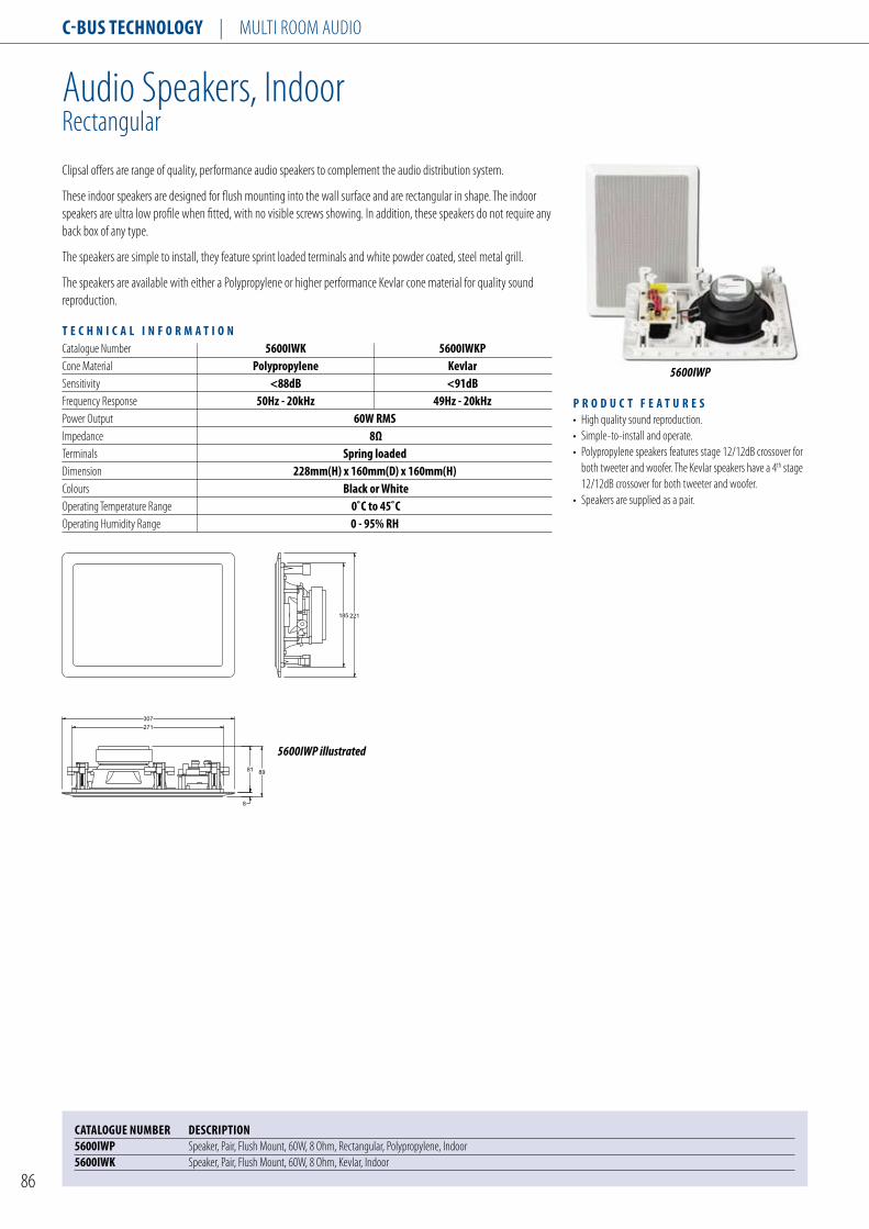
C-Bus TEChnology | MuLtI ROOM AuDIO
86
Audio speakers, IndoorRectangular
Clipsal offers are range of quality, performance audio speakers to complement the audio distribution system.
these indoor speakers are designed for flush mounting into the wall surface and are rectangular in shape. the indoor speakers are ultra low profile when fitted, with no visible screws showing. In addition, these speakers do not require any back box of any type.
the speakers are simple to install, they feature sprint loaded terminals and white powder coated, steel metal grill.
the speakers are available with either a polypropylene or higher performance Kevlar cone material for quality sound reproduction.
T E C h n I C A l I n F o R M A T I o nCatalogue number 5600IWK 5600IWKPCone Material Polypropylene Kevlarsensitivity <88dB <91dBFrequency Response 50hz - 20khz 49hz - 20khzpower Output 60W RMsImpedance 8Ωterminals spring loadedDimension 228mm(h) x 160mm(D) x 160mm(h)Colours Black or WhiteOperating temperature Range 0˚C to 45˚COperating Humidity Range 0 - 95% Rh
P R o D u C T F E A T u R E s• High quality sound reproduction.• simple-to-install and operate.• polypropylene speakers features stage 12/12dB crossover for both tweeter and woofer. the Kevlar speakers have a 4th stage 12/12dB crossover for both tweeter and woofer.• speakers are supplied as a pair.
5600IWP
CATAloguE nuMBER DEsCRIPTIon5600IWP speaker, pair, Flush Mount, 60W, 8 Ohm, Rectangular, polypropylene, Indoor5600IWK speaker, pair, Flush Mount, 60W, 8 Ohm, Kevlar, Indoor
307
271
81
8
89
221185
5600IWP illustrated

C-Bus TEChnology | MuLtI ROOM AuDIO
87
Audio speakers, IndoorCircular
Clipsal offers are range of quality, performance audio speakers to complement the audio distribution system.
these indoor speakers are designed for flush mounting into the ceiling surface and are circular in shape. the indoor speakers are ultra low profile when fitted, with no visible screws showing. In addition, these speakers do not require any back box of any type.
the speakers are simple to install, they feature sprint loaded terminals and white powder coated, steel metal grill.
the speakers are available with either a polypropylene or higher performance Kevlar cone material for quality sound reproduction.
T E C h n I C A l I n F o R M A T I o nCatalogue number 5600ICP 5600ICKCone Material Polypropylene Kevlarsensitivity <90dBFrequency Response 45hz - 20hzpower Output 60W RMsImpedance 8Ωterminals spring loadedDimension 240mm diameter x 83mm(D)Colours WhiteOperating temperature Range 0˚C to 45˚COperating Humidity Range 10 - 95% Rh
P R o D u C T F E A T u R E s• High quality sound reproduction.• simple-to-install and operate.• polypropylene speakers features stage 12/12dB crossover for both tweeter and woofer. the Kevlar speakers have a 4th stage 12/12dB crossover for both tweeter and woofer.• speakers are supplied as a pair.
CATAloguE nuMBER DEsCRIPTIon5600ICP speaker, pair, Flush Mount, 60W, 8 Ohm, Circular, polypropylene, Indoor5600ICK speaker, pair, Flush Mount, 60W, 8 Ohm, Circular, Kevlar, Indoor
5600ICP
77
5
82
240204
77
5
82
240204
5600ICP illustrated
5600ICK illustrated

C-Bus TEChnology | MuLtI ROOM AuDIO
88
Audio speakers, Outdoorshelf top
Clipsal offers are range of quality, performance audio speakers to complement the audio distribution system.
the outdoor speakers are designed to accurately reproduce high fidelity music in an outdoor environment. With a rigid, high-impact plastic cabinet, polypropylene drivers and powder coated metal grilles. the outdoor speakers should be installed in a weather-protected environment, such as under an eave or verandah.
the speakers are simple to install, they feature sprint loaded terminals for easy cable terminations. the speakers are supplied with adjustable mounting brackets for quick installation.
T E C h n I C A l I n F o R M A T I o nCone Material Polypropylenesensitivity <88dBFrequency Response 55hz - 20khzpower Output 35W RMsImpedance 8Ωterminals spring loadedDimensions 305mm(h) x 218mm(W) x 94mm(D)Colours Black or WhiteOperating temperature Range 0˚C to 45˚COperating Humidity Range 10 - 95% Rh
P R o D u C T F E A T u R E s• High quality sound reproduction.• simple-to-install and operate.• polypropylene speakers features stage 12/12dB crossover for both tweeter and woofer.• speakers are supplied as a pair.
5600ODP
CATAloguE nuMBER DEsCRIPTIon5600oDP speaker, pair, shelf top, 60W, 8 Ohm, polypropylene, Outdoor
193
144
66
218
162

C-Bus TEChnology | sOFtWARE pACKAGEs
89
HomeGate software v4.0
the HomeGate software package is a powerful yet easy to use software application that provides a simple-to-use graphical interface to C-Bus from a personal computer. HomeGate has been especially developed for the novice user and the residential market. using HomeGate it is possible to control and monitor your home’s automation system from the pC, including from a remote location over the Internet.
this version of HomeGate features a user programmable logic engine that allows the user to create and run scenarios, events and routines.
the programming language used in the logic engine is similar to the pascal computer language, and the HomeGate provides two programming methods. Wizards allow the novice user to set or create simple programs while for the more advanced user a text based editor is available for more complex and sophisticated functions.• scheduling of events based on time and date.• Conditional logic (IF tHEn, AnD, OR, nOt etc.)• Flow Control (FOR, REpEAt, WHILE).• Variables (Integer, Real, Boolean, Character, string).• Arithmetical calculations.
the logic engine also supports other applications including:• Control and monitoring of C-Bus Group Addresses and scenes.• serial and tCp/Ip interfaces.• Data and event logging.• user inputs and outputs.• Edge triggered events.
P R o D u C T F E A T u R E s Major additions and enhancements found in this version of the application include:• Ability for components to control system input and output variables.• special functions allow users to set: - Internet & networking properties - Display system properties (processor, memory, etc.) - select screen saver - time zone, time and date format - sound files and store scenes.• support for multiple project themes.• Automatic scene creation.• supports embedded Web pages.• supports animated bitmap graphics.• Improved and enhanced libraries of bitmaps, icons and backgrounds.• Automatic component labelling.
5000DHG2/4
CATAloguE nuMBER DEsCRIPTIon5000Dhg2/4 HomeGate Application software, two network5000Dhg10/4 HomeGate Application software, ten network

C-Bus TEChnology | sOFtWARE pACKAGEs
90
schedule plus software, v4.0
the schedule plus software package is a powerful software application that provides a simple-to-use yet powerful graphical interface to C-Bus, from a personal computer. schedule plus has been especially developed for the facilities or building manager in the commercial market. using schedule plus it is possible to automate your building’s lighting control system and provides a centralised, real-time management of the building’s electrical services.
this version of schedule plus features a user programmable logic engine that allows the user to create and run scenarios, events and routines. In addition, schedule plus features an enhanced and powerful schedular program that provides the building owner with increased flexibility for time management and event driven tasks.
the programming language used in the logic engine is similar to the pascal computer language, and the schedule plus provides two programming methods. Wizards allow the novice user to create simple programs while for the more advanced user, a text based editor is available for more complex and sophisticated functions.• scheduling of events based on time and date.• Conditional logic (IF tHEn, AnD, OR, nOt etc.)• Flow Control (FOR, REpEAt, WHILE).• Variables (Integer, Real, Boolean, Character, string).• Arithmetical calculations.
the logic engine also supports other applications including:• Control and monitoring of C-Bus Group Addresses and scenes.• serial and tCp/Ip interfaces.• Data and event logging.• user inputs and outputs.• Edge triggered events.
P R o D u C T F E A T u R E sMajor additions and enhancements found in this version of the application include:• Ability for components to control system input and output variables.• special functions allow users to set: - Internet & networking properties - Display system properties (processor, memory, etc.) - select screen saver - time zone, time and date format - sound files and store scenes.• support for multiple project themes.• Automatic scene creation.• supports embedded Web pages.• supports animated bitmap graphics.• Improved and enhanced libraries of bitmaps, icons and backgrounds.• Automatic component labelling.
CATAloguE nuMBER DEsCRIPTIon5000DsP2/4 schedule plus Application software, two network5000DsP10/4 schedule plus Application software, ten network5000DsPu/4 schedule plus Application software, unlimited network License
5000DSP2/4

OccupancySensors

Occupancy SenSOrS
92
Ultrasonic Sensor, Corridors
752/135U
The ultrasonic corridor sensor has been specifically designed to detect movement inside buildings and activate lighting for a pre-determined period in response. These sensors feature a detection pattern that is asymmetrically, with coverage up to 4.6m x 30m and field of view of 360˚, ideal for use in corridors and passages.
Ultrasonic detectors use a high frequency signal to detect movement. The detection method of ultrasonic detectors is superior when compared with infrared sensors, as ultrasonic sensors are more sensitive to fine movements. In addition, ultrasonic sensors have a greater coverage range, which means fewer sensors are required to cover the same area.
The ultrasonic sensors are supplied with a separate power pack, which features a voltage free relay contact that may be used to signal a building management system, when lighting has been activated. In this way the control of the air-conditioning for instance may be synchronized to lighting, providing additional energy savings for that zone.
The sensors feature a user adjustable time delay and detection range and a logic bypass switch to force all lights on independent of the sensor. All controls are conveniently located on the front of the unit.
p r O D u c T F e a T u r e S • Simple to install and commission. • Designed for indoor applications to cover a large area. • Fully adjustable range sensitivity and time delay. • Retrigger time delay each time movement is detected. • Lock out feature to turn lights on for emergency and commissioning purposes. • High frequency audible cannot be detected and harmless to humans. • Walk test LED for commissioning. • 2 years manufacturers warranty. • BMS/EMS contacts. • C-Tick (Australia/New Zealand), CE (European Community).
caTalOgue number DeScripTiOn752/135u Ultrasonic Sensor, Corridors, 4.5m x 30m
T e c H n i c a l i n F O r m a T i O n Catalogue Number 752/135u Supply Voltage 192-264Vac, 50/60Hz Load Current 7.5a switched active Minimum Load 0ma Detection Method ultrasonic Operating Frequency 32.7kHz Status Indicators red leD BMS/EMS Inputs isolated changeover relays Compatible Loads incandescent and fluorescent Time Adjustment 0.5 - 30 mins Mounting Height 2.4 nominal, (2.2 to 3.4m) Field of View 360˚ Detection Area 4.6m x 30m (max.) Mounting Surface mount Application corridors (indoors) Warm Up Time 5 seconds Operating Temperature Range 0˚c to 50˚c Operating Humidity Range 10 - 95% rH
128
35
77

Occupancy SenSOrS
93
Ultrasonic Sensor, 360 Degrees
752/225CU
The ultrasonic sensor has been specifically designed to detect movement inside buildings and activate lighting for a pre-determined period in response. These sensors feature a detection pattern that is symmetrically, with coverage up to 12m x 12m and field of view of 360˚, suitable for large open spaces in building.
Ultrasonic detectors use a high frequency signal to detect movement. The detection method of ultrasonic detectors is superior when compared with infrared sensors, as ultrasonic sensors are more sensitive to fine movements. In addition, ultrasonic sensors have a greater coverage range, which means fewer sensors are required to cover the same area.
The ultrasonic sensors are supplied with a separate power pack, which features a voltage free relay contact that may be used to signal a building management system, when lighting has been activated. In this way the control of the air-conditioning for instance may be synchronized to lighting, providing additional energy savings for that zone.
The sensors feature a user adjustable time delay and detection range and a logic bypass switch to force all lights on independent of the sensor. All controls are conveniently located on the front of the unit.
p r O D u c T F e a T u r e S • Simple to install and commission. • Designed for indoor applications to cover a large area. • Fully adjustable range sensitivity and time delay. • Retrigger time delay each time movement is detected. • Lock out feature to turn lights on for emergency and commissioning purposes. • High frequency audible cannot be detected and harmless to humans. • Walk test LED for commissioning. • 2 years manufacturers warranty. • BMS/EMS contacts. • C-Tick (Australia/New Zealand), CE (European Community).
T e c H n i c a l i n F O r m a T i O n Catalogue Number 752/225cu Supply Voltage 192-264Vac, 50/60Hz Load Current 7.5a switched active Minimum Load 0ma Detection Method ultrasonic Operating Frequency 32.7kHz Status Indicators red leD BMS/EMS Inputs isolated changeover relays Compatible Loads incandescent and fluorescent Time Adjustment 0.5 - 30 mins Mounting Height 2.4 nominal, (2.2 to 3.4m) Field of View 360° Detection Area 12.1m x 12.1m (max.) Mounting Surface mount Application large open work areas (indoors) Warm Up Time 5 secondsDimensions 125mm diameter x 43mm(H)Operating Temperature Range 0˚c to 50˚c Operating Humidity Range 10 - 95% rH
caTalOgue number DeScripTiOn752/225cu Ultrasonic Sensor, 360 Degrees, 12m x 12m
125
43

Occupancy SenSOrS
94
Ultrasonic Sensor, Dual Technology
752/225CUI
The dual ultrasonic and infrared sensor has been specifically designed to detect movement inside buildings and to activate lighting for a pre-determined period in reponse. This sensors feature a detection pattern that is symmetrical, with coverage up to 15m x 15m and a field view of 360˚, suitable for large open spaces in buildings.
The sensors feature dual technologies of ultrasonic and infrared. Ultrasonic detectors use a high frequency signal to detect movement while infrared sensors, detect the movement of a thermal body within the detection area. The reliability of detection is optimised when both technologies are used. It is possible to select between infrared or ultrasonic or both if required. The application of both technologies ensures ultimate performance in both the near field (infrared) and far field (ultrasonic) detection.
The dual sensors allows the building owner to tailor each sensor for a particular application, for instance the ultrasonic sensor may be disabled when the unit is installed near an air-conditioning vent for instance.
The ultrasonic sensors are supplied with a separate power pack, which features a voltage free relay contact that may be used to signal a building management system, when lighting has been activated. In this way the control of the air-conditioning for instance may be synchronised to lighting, providing additional energy savings for that zone.
The sensors feature a user adjustable time delay and detection range and a logic bypass switch to force all lights on independent of the sensor. All controls are conveniently located on the front of the unit.
p r O D u c T F e a T u r e S • Dual technology for maximum detecton reliability. • Designed for indoor applications to cover a large area. • Fully adjustable range sensitivity and time delay. • Retrigger time delay each time movement is detected. • Lock out feature to turn lights on for emergency and commissioning purposes. • High frequency audible cannot be detected and harmless to humans. • Walk test LED for commissioning. • 2 years manufacturers warranty. • BMS/EMS contacts. • C-Tick (Australia/New Zealand), CE (European Community).
T e c H n i c a l i n F O r m a T i O n Catalogue Number 752/225cuiSupply Voltage 192-264Vac, 50/60Hz Load Current 7.5a switched active Minimum Load 0ma Detection Method ultrasonic and infrared Operating Frequency 32.7kHz Status Indicators red leD (ultrasonic) and green leD (infrared)BMS/EMS Inputs isolated changeover relays Compatible Loads incandescent and fluorescent Time Adjustment 0.5 - 30 mins Mounting Height 2.4 nominal, (2.2 to 3.4m) Field of View 360° Detection Area 15.2m x 15.2m (max.) Mounting Surface mount Application large open work areas (indoors) Warm Up Time 5 seconds Operating Temperature Range 0˚c to 50˚c Operating Humidity Range 10 - 95% rH
caTalOgue number DeScripTiOn752/225cui Ultrasonic and Infrared Dual Technology Sensor, 360 Degrees, 15m x 15m
125
6

Occupancy SenSOrS
95
Passive Infrared Sensors, Outdoor 90 Degrees
751
The indoor infrared occupancy sensors are designed to detect movement of a thermal body and activate lighting for a pre-determined time interval in response. These sensors are ideally suited to small offices, storerooms and bathrooms. The occupancy sensors are designed for corner mounting and feature a detection range of 36m2 and field of view of 90˚.
Besides the obvious convenience of automatic lighting control, the 751 series of occupancy sensors can also provide energy and cost savings on both commercial and residential applications.
The devices are designed to trigger each time movement of a thermal body is detected inside the detection range of the sensor. The period that lighting can be controlled is adjustable from 5 seconds to 20 minutes. The user can also adjust the minimum light threshold at which the sensor activates; this ensures lights are only turned on when the ambient light level is low.
p r O D u c T F e a T u r e S • Simple-to-install and commission. • Sensor head can rotate through 120 degrees, permitting sensor head to be accurately located to target. • Fully adjustable light threshold and time delay. • Retrigger time delay each time movement is detected. • 2 years manufacturers warranty. • C-Tick (Australia/New Zealand), CE (European Community), FCC (United States) compliant.
T e c H n i c a l i n F O r m a T i O n Catalogue Numbers 751 751r Supply Voltage 192-264Vac, 50/60Hz Installation 2 wires (no neutral) 3 wires (requires neutral) Load Current 2a 10a Minimum Load 20ma 0ma Leakage Current in Off State 2ma 0ma Detection Method passive infrared detection of a thermal body Compatible Loads incandescent and fluorescent Time Adjustment 5 sec - 20 min Mounting Height 2.4 nominal, (2.0 to 3.2m) Field of View 90˚Detection Area 6m x 6m, 90˚ from sensor head. Adjustment Head can rotate through 120˚ when installed. Mounting Surface mount Warm Up Time 5 seconds IP Rating ip44 Load Termination Screw Terminals (3 x 2.5mm2) Dimensions 100mm diameter x 57mm Operating Temperature Range 0˚c to 40˚c Operating Humidity Range 10 - 95% rH
caTalOgue number DeScripTiOn751 Infrascan, 2A, 90 Degrees, 2 Wires751r Infrascan, 10A, 90 Degrees, 3 Wires751mb Mounting Base for 751 Series
-+
-+
VIE
W 108
18
70
R48
90˚ Fieldof View
751 illustrated

Occupancy SenSOrS
96
Passive Infrared Sensors, Outdoor 110 Degrees
750WP
The Infrascan is a highly reliable motion detector, designed for outdoor applications. The unit features an IP rating, IP66 and is designed to operate in direct weather. The unit is manufactured from UV stabilized plastic and designed for years of maintenance free service and reliable operation.
The sensors are designed to detect movement of a thermal body and activate lighting for a predetermined time interval in response. These sensors are ideally suited for driveways, perimeter lighting, storerooms and stairwells. The sensors are designed for ceiling or wall mounting and feature a detection range of 18m radius and field of view of 110˚.
The sensor features a multi zone Frensel lens design for optimum and reliable detection capability. The advanced electronics and lens design, divides the field of view into 48 zones located at 4 different levels, ensuring immediate reaction to body movement and reducing the number of dead zones that can be penetrated.
Besides the obvious convenience of automatic lighting control, the 750 series of occupancy sensors can also provide energy and cost savings on both commercial and residential applications.
The devices are designed to trigger each time movement of a thermal body is detected inside the detection range of the sensor. The period that lighting can be controlled is adjustable from 5 seconds to 8 minutes. The user can also adjust the minimum light threshold at which the sensor activates; this ensures lights are only turned on when the ambient light level is low. In addition, the user can adjust the sensitivity (range) from a maximum of 18m.
The sensors feature user adjustable light level threshold, range sensitivity and time delay that are accessible from the front of the unit.
p r O D u c T F e a T u r e S • Simple-to-install and commission. • Manufactured from UV stabilized plastic. • IP66 rated, can be installed in direct weather. • Features multi zone Frensel lens for superior detection capability. • Fully adjustable light threshold, range and time delay. • Retrigger time delay each time movement is detected. • 5 year manufacturers warranty. • C-Tick (Australia/New Zealand), CE (European Community), FCC (United States) compliant.
T e c H n i c a l i n F O r m a T i O n Catalogue Numbers 750Wp 750Wpr Supply Voltage 192-264Vac, 50/60Hz Installation 2 wires (no neutral) 3 wires (requires neutral) Load Current 5a 10a Minimum Load 20ma 0ma Leakage Current in Off State 2ma 0ma Detection Method passive infrared detection of a thermal body Compatible Loads incandescent and fluorescent Time Adjustment 5 sec - 8 min Mounting Height 2.4 nominal, (2.0 to 3.2m) Field of View 110˚Detection Area 18m radius x 110˚ Mounting Surface mount Warm Up Time 5 seconds IP Rating ip66 Operating Temperature Range 0˚c to 50˚c
caTalOgue number DeScripTiOn750Wp Infrascan, 5A, 110 Degrees, 2 Wires, IP66750Wpr Infrascan, 10A, 110 Degrees, 3 Wires, IP66
InFRASCAN
74
111
20 38
58
138
R
750WP illustrated

Occupancy SenSOrS
97
Passive Infrared Sensors, Indoor 360 Degrees
753
The indoor infrared occupancy sensors are designed to detect movement of a thermal body and activate lighting for a pre-determined time interval in response. These sensors are ideally suited to small offices, storerooms and bathrooms. The occupancy sensors are designed for ceiling mounting and feature a detection range of 12m x 12m and field of view of 360˚.
The sensor features a multi zone Frensel lens design for optimum and reliable detection capability.
Besides the obvious convenience of automatic lighting control, the 753 series of occupancy sensors can also provide energy and cost savings on both commercial and residential applications.
The devices are designed to trigger each time movement of a thermal body is detected inside the detection range of the sensor. The period that lighting can be controlled is adjustable from 5 seconds to 20 minutes. The user can also adjust the minimum light threshold at which the sensor activates; this ensures lights are only turned on when the ambient light level is low.
The sensors feature user adjustable light level threshold and time delay that are accessible from the front of the unit.
p r O D u c T F e a T u r e S • Simple-to-install and commission. • Flush mount design.• Features multi zone Frensel lens.• Fully adjustable light threshold and time delay. • Retrigger time delay each time movement is detected. • 5 years manufacturers warranty. • C-Tick (Australia/New Zealand), CE (European Community), FCC (United States) compliant.
T e c H n i c a l i n F O r m a T i O n Catalogue Numbers 753 753r Supply Voltage 192-264Vac, 50/60Hz Installation 2 wires (no neutral) 3 wires (requires neutral) Load Current 2a 10a Minimum Load 20ma 0ma Leakage Current in Off State 2ma 0ma Detection Method passive infrared detection of a thermal body Compatible Loads incandescent and fluorescent Time Adjustment 5 sec - 20 min Mounting Height 2.4 nominal, (2.0 to 3.2m) Field of View 360˚Detection Area 12m x 12m, at a height of 2.4mMounting Flush mount Warm Up Time 5 seconds IP Rating ip44 Load Termination Screw Terminals (3 x 2.5mm2) Dimensions 72mm diameter x 103mm Operating Temperature Range 0˚c to 50˚c Operating Humidity Range 10 - 95% rH
caTalOgue number DeScripTiOn753 Infrascan, 2A, 360 Degrees, 2 Wires753r Infrascan, 10A, 360 Degrees, 3 Wires
Warr
anty
Void
If R
em
oved
Unit
Addre
ss
Gro
up
Addre
sses
Netw
ork
12
34
56
MO
D. STATE1036318
88
15
103
47 503672
R
753 illustrated

Occupancy SenSOrS
98

Clipsal Security

Clipsal seCurity | ALARM PANELS
100
MinderPRO Premise Automation Controller
p r O D u C t F e a t u r e s • 8 inputs and 8 outputs zones, expandable to 64 inputs and 64 outputs.• 365 days real time clock for time scheduling and event management.• Supports the C-Bus, EZinstall and X-10 protocols.• Internet enabled via the Clipsal PremiseGateway™.• Programmable from the keypad or by personal computer.• Supports central monitoring station formats.• Voice prompt menu and supports any language.• User programmable voice library.• Intercom function between keypads and phones.• Battery backup for uninterrupted operation.• Infrared engine for the control of audiovisual and air-conditioner appliances.• 16 unique users, supported.• 8 voice mailboxes, supported.• Sturdy metal enclosure.• C-Bus Enabled, with factory certification.• CE and A-Tick compliant.
CatalOGue NuMBer DesCriptiON 5302tCu8/8 Premise Automation Security Controller, 8 Inputs/8 Outputs,16VAC @ 3A Transformer, Mechanical Enclosure Included 5388Cu/2 MinderPRO Controller PCB, 8 Inputs/8 Outputs
The 5302CU series of Premise Automation Controllers are intelligent units for management of residential and commercial buildings with applications in energy effciency, security, lighting control and event scheduling.
The controller features a powerful processor and is suited at applications where specific reactions are required to particular events. The unit is simple to install, program and use, and features a voice prompt menu that navigates the user through the various menus and options. The user can control any device connected to the controller, via the local keypad or any dial tone phone.
The premise controller features an 8-zone security system, which may be expanded to 64 zones. The controller features a telephone dialler and supports central monitoring to a base station. The telephone dialler and voice engine also permits a handy duplex intercom station, between keypads and between keypads and a phone.
Scheduling of events and time management control of devices is facilitated by the on board real time clock. Several time programs can run simultaneously on the controller.
The controller can be interfaced to third party systems such as the C-Bus control system realising an integrated lighting control solution. In addition, the premise controller supports EZinstall and the X-10 power line standard.
The Clipsal MinderPRO premise automation controller is specifically designed for residential and small commercial automation applications. With the addition of the Clipsal PremiseGateway™, the controller can be web-enabled realising control of devices over the Internet, via a secure encrypted connection.
In addition, the Clipsal MinderPRO controller PCB is available as a separate item for those installations which require a custom enclosure.
5302TCU8/8

Clipsal seCurity | ALARM PANELS
101
MinderPRO Premise Automation Controller
t e C H N i C a l i N F O r M a t i O N Catalogue Number 5302tCu8/8Inputs 8 digital (protected loop), surge protectedOutputs 8 open collector (12V) pulsed, latched and infraredKeypads Maximum 8 keypads per base controllerDoor Stations Maximum 3 door stations per base controllerPower Supply supplied with 16VaC @ 3a transformerPower Supervision supervised mains power failure and battery low conditionAuxiliary Power Output 12VDC @ 1a (max)Battery Backup 12VDC @ 7a Hr (not included)Central Monitoring all major pulse formats, surgard, Contact iDSiren Tones 20 siren patterns, 2 sound levels, user programmableSiren and Strobe Output yesTelephone Dialler 8 numbersEvent Log 250 entriesUser Codes 16 unique codesMail Boxes 8 unique mail boxesAlarm Types 31Answering Machine 10 minutes, uses solid state memoryTime Programs 16 independent programsResponses/Macros 255 (including C-Bus devices)C-Bus requires addition of C-Bus/serial interface 5350CBX-10 standardEZinstall ULTI requires the addition of serial/ulti interface cardInternet Connection requires addition of serial interface 5350uCM, use with Clipsal premiseGateway™Controller Case Wall mounted, mild steel, with key lockDimensions 310mm(W) x 350mm(l) x 95mm(D)Weight 4.7kgOperating Temperature Range 0˚C to 40˚COperating Humidity Range 35 - 85% rH

Clipsal seCurity | ALARM PANELS
102
LED Keypad
The Clipsal MinderPRO Keypad provides a user-friendly interface to the Premise Controller. The Keypad is used to program, control and monitor status of devices connected to the controller and supports up to 16 unique users with one-touch arming feature for ‘Away’, ‘Night’, ‘Day’ and ‘Vacation’ modes.
In addition, the Keypad features a built-in microphone input that can be used to record voice messages and speaker output to annunciate voice messages and instructions. The Keypad is equipped with status indicators to report the state of mains power, battery power, security mode and message waiting notification. An infrared receiver also enables the control menu to be controlled from a PDA device.
The front panel of the Keypad comprises of 16 soft touch backlit keys and supports 64 input zones. The zone status is reported through the Keypad via an audio message.
t e C H N i C a l i N F O r M a t i O NCatalogue Number 5316KpBacklighting yes, programmableOne Touch Arming yes, programmableAudio Built-in microphone, speaker and volume adjustStatus Indicators Battery, mains power, message, security off/armed Number of Units up to 8 Keypads per systemIntercom Between Door station, leD or lCD Keypads and phonePanic Buttons 2 key panic and fire buttonIR Receiver Control from pDa deviceTactile Keys 16, soft touch, backlitColours WhiteDimensions 85mm(W) x 160mm(H) x 33mm(D)Operating Temperature Range 0˚C to 40˚COperating Humidity Range 35 - 85% rH
p r O D u C t F e a t u r e s• One touch arming, simple-to-use.• Built-in voice recorder and answering machine, for reminders and message annunciation.• Voice messaging programmable in any language.• Built-in infrared receiver for control from a PDA device.• Backlight push buttons, for night operation.• Simple 4-wire connection.• Premise Controller, supports up to 8 Keypads.• Attractive finish and appearance.• CE and C-Tick compliant.
CatalOGue NuMBer DesCriptiON5316Kp Keypad, LED
5316KP
*
7
0
8
4
1 2
5
F#
9
3
6
85 37
160
2537

Clipsal seCurity | ALARM PANELS
103
LCD Keypad
The Clipsal MinderPRO Keypad provides a user-friendly interface to the Premise Controller. The Keypad is used to program, control and monitor status of devices connected to the controller and supports up to 16 unique users with one-touch arming feature for ‘Away’, ‘Night’, ‘Day’ and ‘Vacation’ modes.
The Keypad’s backlit LCD screen can display up to 2 rows of 16 characters. In addition, the keypad features a built-in microphone input that can be used to record voice messages and speaker output to annunciate voice messages and instructions. The Keypad is equipped with status indicators to report the state of mains power, battery power, security mode and message waiting notification. An infrared receiver also enables the control menu to be controlled from a PDA device.
The front panel of the Keypad comprises of 16 soft touch backlit keys and supports 64 input zones. The zone status is reported through the Keypad via an audio message. The LCD Keypad is interchangeable and operates with the LED Keypad. The two can be connected to the same controller at any time.
CatalOGue NuMBer DesCriptiON5316KpH216 Keypad, LCD, Horizontal
5316KPH216
t e C H N i C a l i N F O r M a t i O N Catalogue Number 5316KpH216Display lCD, 2 rows of 16 charactersBacklighting yes, programmableOne Touch Arming yes, programmableAudio Built-in microphone, speaker and volume adjustStatus Indicators Battery, mains power, message, security off/armedNumber of Units up to 8 Keypads per system Intercom Between Door station, leD or lCD Keypads and phonePanic Buttons 2 key panic and fire buttonIR Receiver Control from pDa deviceTactile Keys 16, soft touch, backlitColours WhiteDimensions 160mm(W) x 85mm(H) x 33mm(D)Operating Temperature Range 0˚C to 40˚COperating Humidity Range 35 - 85% rH
p r O D u C t F e a t u r e s • Large, easy-to-read LCD display.• One touch arming, simple-to-use.• Built-in voice recorder and answering machine, for reminders and message annunciation.• Voice messaging programmable in any language.• Built-in infrared receiver for control from a PDA device.• Backlight push buttons, for night operation.• Simple 4-wire connection.• Premise Controller, supports up to 8 Keypads.• Compatible with the Clipsal MinderPRO LED Keypad.• Attractive finish and appearance.• CE and C-Tick compliant.
158
158 29
89
29
15

Clipsal seCurity | ALARM PANELS
104
Expansion Modules, Local
The Expansion Modules work in conjunction with the Clipsal MinderPRO Premise Automation Controller or Slave Expansion Panels to increase the input/output capacity of the base unit and increase the number of zones that may be monitored or controlled by the Premise Controller.
The Local Expansion Modules are I/O units and are available with 8 inputs, 8 inputs/8 outputs or 16 inputs. Each module is designed to fit into the Premise Controller or Slave Expansion Panel.
All inputs are surge protected from static discharge and all outputs are 12V open collector type.
With the addition of these Expansion Modules the total capacity of the Premise Controller can be expanded up to 64 inputs and 64 outputs.
t e C H N i C a l i N F O r M a t i O NCatalogue Number 5352eXl8/8 5352eXl8/0 5352eXl16/0Inputs 8 digital (protected loop) 16 digital surge protected (protected loop) surge protectedOutputs 8 open collector 0 (12V) pulsed, latched and infrared Power Supply powered from slave expansion unit or premise automation ControllerDimensions 108mm x 88mmOperating Temperature Range 0˚C to 40˚COperating Humidity Range 35 - 85% rH
p r O D u C t F e a t u r e s• The Local Expansion modules are available with 8 inputs, 8 inputs/8 outputs or 16 inputs.• The Local Expansion modules are designed to fit into the Clipsal MinderPRO Premise Automation Controller or Slave Expansion Panel.• All inputs are surge protected.• Expands the system capacity to 64 inputs and 64 outputs.• Features removable terminal blocks for ease of wiring and maintenance.• CE and C-Tick compliant.
5352EXL8/8
CatalOGue NuMBer DesCriptiON5352eXl8/8 Expansion Module, Local, 8 Inputs/8 Outputs5352eXl8/0 Expansion Module, Local, 8 Inputs5352eXl16/0 Expansion Module, Local, 16 Inputs

Clipsal seCurity | ALARM PANELS
105
Expansion Module, Slave
The Expansion Module work in conjunction with the Clipsal MinderPRO Premise Automation Controller to increase the input/output capacity of the base unit and increase the number of zones that may be monitored or controlled by the Premise Controller.
The Slave Expansion Module is an I/O unit, featuring 8 inputs and 8 outputs and is supplied with a mechanical enclosure with space for one Local Expansion Card and battery backup. In addition, Local Expansion Cards are designed to fit into the Premise Controller or Slave Expansion Panel and are available in various I/O configurations.
With the addition of these Expansion Modules the total capacity of the Premise Controller can be expanded up to 64 inputs and 64 outputs.
The Expansion Panel PCB is a seperate add-on and is available in 8 inputs and 8 outputs configuration.
t e C H N i C a l i N F O r M a t i O N Catalogue Number 5352teXs8/8Inputs 8 digital (protected loop) surge protectedOutputs 8 open collector (12V) pulsed, latched and infraredPower Supply supplied with 16VaC @ 3a transformerBattery Backup 12VDC @ 7a Hr (not included)Remote Expansion Bus rs485Mechanical Enclosure Wall mounted, mild steel, with key lockDimensions 310mm(W) x 350mm(H) x 95mm(D)Operating Temperature Range 0˚C to 40˚COperating Humidity Range 35 - 85% rH
p r O D u C t F e a t u r e s • The Slave Expansion unit is supplied with a mechanical enclosure, power supply* and provision for battery backup. (*T versions only)• The Slave Expansion unit features 8 inputs (protected loop) and 8 open collector outputs.• A maximum of 3 Slave Expansion modules may be connected to the Premise Automation Controller.• All inputs are surge protected.• Expands to 64 inputs and 64 outputs.• CE and C-Tick compliant.
CatalOGue NuMBer DesCriptiON5352teXs8/8 Expansion Panel, Slave, 8 Input/8 Output, 16VAC @ 3A Transformer, Mechanical Enclosure Included5388se/2 Slave Expansion PCB, 8 Inputs/8 Outputs
5352TEXS8/8

Clipsal seCurity | ALARM PANELS
106
Interface Modules
The Clipsal MinderPRO Premise Controller supports integration to third party systems via the serial RS232 interface.
The controller supports up to 8 serial interface modules, connecting systems such as Clipsal C-Bus Control System, EZinstall and the Clipsal PremiseGateway™.
The serial interface modules which are located in the controller enclosure are powered from the auxiliary power supply.
The general purpose serial interface connects a PC to the controller for PC programming. This interface also features an IR learner to read and store third party IR codes that are downloaded to the controller.
The C-Bus serial interface provides a connection to Clipsal C-Bus, while at the same time providing a system clock and network burden. The interface card also enables optical isolation between C-Bus and the controller for added safety.
t e C H N i C a l i N F O r M a t i O N Catalogue Number 5350CB 5350/XXXut 5350uCMPC Programming No No yesClipsal PremiseGateway™ No No yesInterface IR Learn/Download Facility No No yesC-Bus Interface yes No NoEZinstall Interface No yes NoEZinstall Control 0 40 devices, 40 scenes 0Number of Interfaces 1 1 8Connection to Clipsal MinderPRO 12V, COM, Ka, KB (rs485)Supply Current 50ma @ 12VDCC-Bus Supply Current 22ma @ 36VDC 0 0C-Bus Group Addresses 255 maximum 0 0Dimensions 108mm x 88mmOperating Temperature Range 0˚C to 40˚COperating Humidity Range 35 - 85% rH
p r O D u C t F e a t u r e s • Provides 2 way serial (RS232) communications between controller and third party systems.• Connects to Clipsal C-Bus control system.• Provides connection between Controller and PC for programming. • Provides connection between Controller and Clipsal PremiseGateway™ for Internet connection.• Features an IR learn and download facility to Controller memory. • Controller supports up to 8 serial cards.• CE and C-Tick compliant.
5350UCM
CatalOGue NuMBer DesCriptiON5350CB Interface Module, Serial to C-Bus5350uCM Interface Module, Serial, Universal5350/434ut Serial to EZinstall Interface, 434MHz5350/315ut Serial to EZinstall Interface, 315MHz
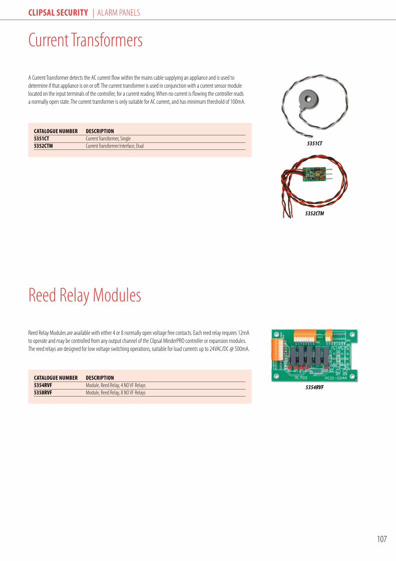
Clipsal seCurity | ALARM PANELS
107
Current Transformers
A Current Transformer detects the AC current flow within the mains cable supplying an appliance and is used to determine if that appliance is on or off. The current transformer is used in conjunction with a current sensor module located on the input terminals of the controller, for a current reading. When no current is flowing the controller reads a normally open state. The current transformer is only suitable for AC current, and has minimum threshold of 100mA.
Reed Relay Modules are available with either 4 or 8 normally open voltage free contacts. Each reed relay requires 12mA to operate and may be controlled from any output channel of the Clipsal MinderPRO controller or expansion modules. The reed relays are designed for low voltage switching operations, suitable for load currents up to 24VAC/DC @ 500mA.
5351CT
CatalOGue NuMBer DesCriptiON5351Ct Current Transformer, Single5352CtM Current Transformer Interface, Dual
Reed Relay Modules
CatalOGue NuMBer DesCriptiON5354rVF Module, Reed Relay, 4 NO VF Relays5358rVF Module, Reed Relay, 8 NO VF Relays
5354RVF
5352CTM

Clipsal seCurity | ALARM PANELS
108
Commissioning Tool
The Zone Test Switch consists of two momentary switches that are plugged into the 3-pin input terminals of the Clipsal MinderPRO controller. Each switch may be configured via shunts as normally open or normally closed. This makes the module very useful for testing and troubleshooting.
5350ZTS
Infrared Module
CatalOGue NuMBer DesCriptiON5350irM Module, Infrared LED
CatalOGue NuMBer DesCriptiON5350Zts Zone Test Switch
5350IRM
The Infrared Transmitter module is connected to any of the outputs on the Clipsal MinderPRO controller, including any of the expansion modules. The module allows transmission of the IR codes from the controller, to control AV and air-conditioning equipment. The Infrared Transmitter module has an 8m line of sight operation.

TechnicalInformation

Technical informaTion
110
C-Bus Wireless System Operation
The C-Bus Wireless product range incorporates a family of C-Bus Radio Frequency (RF) devices, including Wall Plates, Plug Adaptors, Remote Control and a Gateway to Category 5 Wired C-Bus units.
C-Bus Wireless Wall Plates are designed to easily replace standard, 240V wall switches. They incorporate patented Clipsal technology and are two wires devices requiring no Neutral (240VAC Active and Load connections only).
All C-Bus Wireless units incorporate Clipsal C-Bus’ unique Learn Mode functions for programming devices. Wall Plates, Plug Adaptors and the Gateway unit can also be programmed via the C-Bus Toolkit software. Multiple C-Bus Wireless units can be linked into a common network using Learn Mode or the C-Bus Toolkit software.
Associations can be created between buttons on multiple units, so that a button press on one unit will operate a button on another (and the connected lights or other electrical devices).
C-Bus Wireless units include scene capabilities, which allow the user to perform a series of actions across multiple outputs by pressing a single button. For example, on arrival home a home owner could use a scene to switch on lights in the hallway, kitchen and lounge, and also switch on a heater.
The diagrams below show two of the many possible basic C-Bus Wireless unit installations. Room A uses stand-alone units, which can be switched via the Wireless Remote Control. Room B uses networked units where buttons on one unit can operate other units or trigger scenes.
Programming a C-Bus Wireless via C-Bus Toolkit Software
Grouping C-Bus Wireless Units via Learn Mode
Room AStandalone C-Bus Wireless Units
Room BNetworked C-Bus Wireless Units
10 secondpress
Step 1 Step 3
2 secondpress
Step 2
1
3

Technical informaTion
111
C-Bus Wireless System Operation
c-Bus Wireless networksTo experience the full capabilities of wireless operation, C-Bus Wireless units must be linked together to form a network.
To communicate with each other, units within the same network should be located within 15 to 20 meters of each other. This distance depends on building materials used.
Up to 30 units may be connected within the same C-Bus Wireless network.
Basic operationButtons on a Wireless Wall Plate or Plug Adaptor are organised in pairs that control the output channels (local control buttons). Remaining pairs (free buttons) are used to control outputs on other units when multiple C-Bus Wireless units are configured as part of a network. For example, the figure below shows a 6 button, 2 channel ULTI Wireless Dimmer unit. Its buttons perform the following functions:• Buttons 1 and 2 control the first channel. (A quick press on either button toggles the channel on or off. A long press on button 1 or 2 dims down or up respectively).• Buttons 3 and 4 control the second channel.• Buttons 5 and 6 are unused when the unit is used as a stand-alone unit. They may be used to control outputs on other units when part of a multi-unit network.
When a C-Bus Wireless Wall Plate or Plug Adaptor unit is first installed, it functions as a stand-alone unit. In this basic default mode, the unit functions as a dimmer or switch, depending on the model.
C-Bus Wireless Plug Adaptors have one output channel (a single, 240VAC socket) and two buttons. Wall plate units are available in one or two output channel versions, with two, four, six or eight buttons (eight button, NEO only). Each channel controls one or more lights or other electrical devices connected to its output.
c-Bus Wireless network SecurityC-Bus Wireless units can optionally use 128-bit encrypted messages to communicate with each other. This results in a highly secure network.
nearby c-Bus Wireless networksIt is possible to have several separate networks present alongside each other without interfering, as each separate C-Bus Wireless network has an automatically assigned, unique ‘House Code’.
local controlbuttons
free buttons
1
5
2
6
Two output channels
15 to 20 metres
c-Bus Wireless modes of operationC-Bus Wireless units have five major modes of operation.
Mode 1Stand-alone modeIn this mode, C-Bus Wireless Wall Plates and Plug Adaptors acts as stand-alone dimmers or switches and make no use of the inbuilt wireless capabilities. No setup is required for this mode, Plug Adaptors simply plug into the mains, and Wireless Wall Plates are installed by a licensed electrician in place of existing wall switches. The buttons on the units control the local dimming or switching channels of the unit only.
Mode 2Simple remote controlled modeIn this mode, a C-Bus Wireless Wall Plate acts as a standalone dimmer or switch and a C-Bus Wireless Remote Control operates the Wall Plate from a distance. This mode is simple to set up and is suitable for small installations where networking is not needed. C-Bus Wireless Wall Plate or Plug Adaptor units are controlled using a C-Bus Wireless Remote: In this mode, the buttons on the Wireless Wall Plate control the local dimming or switching channels of the unit, and the Remote Control is linked to buttons on a Wall Plate using a Learn Mode operation. No PC is required.

Technical informaTion
112
C-Bus Wireless System Operation
Mode 5networked mode in combination with category 5 Wired c-Bus Units The C-Bus Wireless Gateway is used to link a C-Bus Wireless network to a C-Bus Category 5 wired network. It is functionally equivalent to a C-Bus Network Bridge. Using the Gateway, C-Bus Wireless and Category 5 networks can communicate and interact with each other. Both Wireless and Category 5 networks use the same command structure, and are 100% compatible.
Mode 3networked modeIn this mode, a C-Bus Wireless Wall Plate acts as a dimmer or switch and multiple C-Bus Wireless units can be linked to each other with the C-Bus Wireless technology. This mode is simple to setup, and is suitable for more complex installations. In this mode, local control buttons control the dimming or switch channel of the unit, and may also control other C-Bus Wireless units. Free buttons can control the dimmer or switch channels of other units via a C-Bus Wireless network established using Learn Mode operations. The operation of buttons is set using Learn Mode operations or using the C-Bus Toolkit Software.
Mode 4networked with remoteIn this mode, a C-Bus Wireless Wall Plate acts as a dimmer or switch and multiple C-Bus Wireless units can be linked to each other with the C-Bus Wireless technology. Local control buttons control the dimming or switch channel of the unit, and may also control other C-Bus Wireless units. Free buttons can control the dimmer or switch channels of other units via a C-Bus Wireless network established using Learn Mode operations or C-Bus Toolkit software. Buttons on the Wireless Remote are linked to Wall Plate and Plug Adaptor buttons as desired.
15 to 20 metres
Shift
AllOff
c-Bus Wireless modes of operation (cont’d)

Technical informaTion
113
C-Bus Wireless Quick Start Guide
creating Your network (getting your units to talk to each other)
Quick Tips• When a switch is put into learn mode the buttons will flash rapidly for approx 5 sec - this is normal. It is best to wait for them to flash slowly before performing your next task unless specified (such as step 3 above).• You can network more than one switch at a time - repeat steps 2 and 3 on following switches before performing steps 4 to 6• Network a plug adaptor exactly the same way as a switch - the buttons are just vertical instead of horizontal.• Once all of your switches are networked they will all automatically go into learn mode the next time it is entered on one of the switches.• It is best to network all of your switches and plug adaptors before moving on to grouping buttons and creating scenes.
Grouping Buttons (getting a button on one or more switches to turn on a light on another switch)
IMPORTANT: If your switch controls two separate lights, you MUST enter learn mode using the two buttons that are connected to the light you wish to control.
Quick Tips• You can turn on a light from several switches - repeat step 3 on other buttons you would like to operate the light before performing step 4.• If the grouped buttons flash after performing step 3, it means you have held the button too long and it has become a timer. If this happens, simply press it twice. This will unnasign the button as a timer it, and reassign it as a group.• If learn mode is entered on a switch whose lights have been used in a group, those buttons will become illuminated after a few seconds instead of flashing alternately.
Press & hold top two buttons on first switch for 10 sec
until they flash alternately (entering Learn Mode).
Press top two buttons on next switch for 10 sec until
they flash alternately (entering Learn Mode).
Press top two buttons again while they are still flashing rapidly (within
approx 5 sec).
Press & hold top left button and do two quick
presses to top right button.
Lights will flash rapidly for several seconds.
Wait until switches returns to learn mode
and buttons flash alternately.
Press & hold top two buttons on either
switch for 1 sec (exit Learn Mode).
You’re done!
S T e P 1 S T e P 2 S T e P 3 S T e P 5 S T e P 6
Press & hold the two buttons that are connected to the light you want to operate
for 10 sec until they flash alternately.
Press the button that controls the light you want
to operate. That light should now turn on.
Press the button(s) on other switch(es) that you want to control the light
you have turned on.
Press & hold top two buttons on either switch
for 1 sec.
You’re done!
S T e P 2 S T e P 3 S T e P 4
Learn
Use
Learn
Use
Use
Learn
Use
Learn
Use
Use
S T e P 4
S T e P 1
OR

Technical informaTion
114
Learn
Use
Learn
Use
Use
Learn
Use
Learn
Use
Use
Learn
Use
Learn
Use
Use
creating Scenes (dimming and turning several lights on or off with the press of one button)
C-Bus Wireless Quick Start Guide
IMPORTANT: Before you can create scenes you must:Part 1: Create a Scene Button as per belowPart 2: Ensure that any buttons that will be included in your scene have either been used in a “group” as per above “Grouping Buttons” section OR “grouped to itself” as per Step 2 below. This is because buttons require an individual “ID” number to be included in a scene which is only given to a button when it is used in a group or grouped to itself.
Quick Tips• If a light you have included in your scene does not turn on it may mean it has not been “grouped” - see “Important, Part 2” section above.• To create an “all off” button for when you go to bed or leave the house, put the scene key into learn mode, then go around your house and turn every light on then off, then exit scene learn mode. The scene button will now turn every light off in your home with one press.• Why not create an “all on” scene in your bedroom as an emergency panic button.• Another great idea is a dimly lit scene in your hallway for when you get up at night to check on the kids.
Part 1 - create your Scene ButtonCreating the button you want to control your scene.
Part 2 - Grouping a Button to “itself”Creating an ID number - if button has not been included in group.
Part 3 - create your SceneNow that you have created your scene button and made sure all of your buttons have their own ID number - it’s time to create your scene.
Press & hold top two buttons for 10 sec until they flash alternately.
Double quick-press the button you want to control your scene.
Press & hold top two buttons for 1 sec.
You’re done!
S T e P 1 S T e P 2 S T e P 3
Press & hold top two buttons for 10 sec until they flash alternately.
Press the button you want to “group to itself”.
Press & hold top two buttons for 1 sec.
You’re done!
S T e P 1 S T e P 2 S T e P 3
Press & hold the scene button for 10 sec until
it flashes (entering Scene Learn Mode).
Turn on any lights to the desired level for your scene.
This may include plug adaptors with lamps.
Press the scene button for 2 sec
(exit Scene Learn Mode).
You’re done!
S T e P 1 S T e P 2 S T e P 3

Technical informaTion
115
Learn
Use
Learn
Use
Use
C-Bus Wireless Quick Start Guide
Programming Your remote control(getting the buttons on your remote control to turn your lights on and off)
Quick Tips• To program other remote buttons at the same time, simply repeat steps 3 to 5 before performing steps 6 and 7.• If you want to reassign a remote button that you have used previously, you must first clear it by doing steps 1 to 2 above, then press the remote button you wish to clear, then do quick double press on any button on the switch.• The “scene” button on the remote allows each remote button to perform a second function. To program the second function, simply press the “Scene” button so that two light bulbs appear in the remote’s blue display immediately before performing step 3 above.
Press & hold top two buttons on any switch for 10 sec
until they flash alternately.
Remove the remote back cover and slide switch to
the “learn” position.
Press the button on the remote you want to control your light.
Press the button on the switch that you want to
control with your remote.
Wait until switches return to learn mode and buttons
flash alternately.
Press & hold top two buttons for 1 sec.
Slide switch to “use” mode and replace back cover.
You’re done!
S T e P 1 S T e P 2 S T e P 3 S T e P 4 S T e P 5 S T e P 6 S T e P 7

Technical informaTion
116
C-Bus Design Guide
1 introductionThe C-Bus SystemClipsal C-Bus is a control system that can be used to control lighting, electrical equipment, audio-visual equipment and other electronic systems in commercial, hotel, industrial and residential installations. A reduction in the amount of mains cabling, reduced installation times, energy savings and extra control system functionality make C-Bus a cost effective alternative to conventional wiring. C-Bus is a microprocessor based system and requires an installer to program the operating variables and control relationships between C-Bus Units. This guide outlines a suggested method for designand installation using C-Bus, and should be read in conjunction with the C-Bus Technical Manual (5000M/2), which provides a detailed overview of the C-Bus system.
ObjectiveThis guide provides a system to aid C-Bus designers; to design and plan C-Bus installations. Additional technical support is offered by Clipsal Integrated Systems offices. If assistance is required, contact your local CIS office.
System RequirementsThe first step in using C-Bus is to define what is required of C-Bus; that is, how devices and electrical loads are to be controlled and what features are required by the installation.
2 methods of System DesignDesign PhilosophyThere are several methods of designing and installing C-Bus. An overview of the installation approach is shown below.
Specification
Site Plan
Map System Requirements
Pla
nnin
gIn
stal
latio
nC
omis
sion
ing
Determine Hardware Requirements
Select NetworkTopology
Create Project /Project Manager
Define Network TopologyTopology Manager
ElectricalInstallation & Unit
ProgrammingC-Bus Installation
Software
Design Changes /Expansion /
Upgrade
Commission Installation

Technical informaTion
117
C-Bus Design Guide
Installation ApproachPlanning and DesignThe most important phase of any C-Bus installation is in the planning and design of the system. Accurate planning requires a good understanding of the capabilities of the system, and the requirements of a successful installation (refer to the Design Checklist). It is also an advantage to fully define the functional specifications for the installation before design work begins. In this way, designers can realise the full potential of the C-Bus system, and get maximum performance from it.
The planning phase usually involves mapping the system requirements, and determining the hardware needs of an installation. Thought should be given as to the placement of the hardware, and the cabling requirements. Programming & functionality requirements should also be fully investigated at this stage. Strict adherence to any documentation procedures is necessary.
InstallationOnce the design phase has been completed, installation may begin. Several simple steps are typically followed:• Implementation of Programming Requirements of the Design on a Personal Computer (Build C-Bus Database).• Unit Initialisation and Programming (One at a Time).• Cabling and Electrical Installation of the Hardware.• Finalization and Further Programming of Units on the Network as required.
The details of the design are first input into a personal computer using the C-Bus Installation Software. Hardware should then be initialised (on a Unit by Unit basis). This involves the assignment of a Unit Address to each Unit, one at a time. In this way Units can be uniquely identified once installed on the Network. It is recommended that each Unit be clearly labeled for easy identification before final electrical fitting takes place. Testing and any further programming may be undertaken at this time, or tackled once all Units have been physically installed.
CommissioningSubject to compliance with the specification, the system may now be commissioned. Modifications or design review can be undertaken at any time, often requiring programming changes only. A well designed system should seldom call for the installation of new hardware, except where revised specifications dictate the necessity.
Programming PrinciplesAll C-Bus devices require programming (with the exception of Power Supplies).This is achieved by dedicated software running on a Personal Computer.Unit programming is carried out to achieve the following objectives:• Create/Define Units on the C-Bus Network• Identify each Unit using the C-Bus addressing convention• Create/Define/Edit control relationships between Inputs and Outputs• Edit Unit operating parameters
The operating parameters vary from Unit to Unit, depending on it’s type. They include:• Key Functions• Timer Functions• Dimming Functions• Toggle (On/Off) Control• Preset Levels• Custom/Other Functions• Output Switching Logic Assignments• Power Fail Recovery Status• Power Up Sequences• Dimming Rates• Indicator Options• Sensor Switching Conditions• Override Controls (Enable/Disable)• Error Status Options
2 methods of System Design

Technical informaTion
118
3 implementing c-Bus DesignsAddressing ConventionsintroductionOnce a basic list of hardware requirements has been established, planning of the programming requirements of an installation can begin. The C-Bus system uses a simple addressing scheme to identify Units, Groups, Applications, Areas, and Networks. The purpose of each parameter will be discussed in the next section.
Group addressingThe Group Address is usually related to the output connected to the terminal of the Output Unit. Hence the Group Address should accurately describe the load or device being controlled. Alternatively, numerical designators can be used for describing outputs such as lighting circuits. Up to 255 Groups in a single C-Bus network can be defined (255 minus the number of Area Addresses defined).
Valid Group Address description include:• Bedroom Lights• L4-2B• Main Office Lights• A4-2L-3• Pool Pump
The default Group is “Unused”.
area addressingThe Area Address is a convenient method of addressing multiple output channels collectively. Large areas consisting of many Units may be controlled from a single point on the C-Bus system. Individual loads (Groups) can still be controlled. Each Unit (Inputs and Outputs) in a control area must be assigned the same Area Address. The Area Address must be unique and must not be repeated as a Group Address in that Application or Network. Up to 255 Areas can be defined (255 minus the number of Group Addresses defined).
Examples of valid Areas are:• House Lights• Banquet Room Lights• Outside Lights
The default Area is “Unused”.
application addressingApplications are used in the C-Bus system to divide the Network into independent functional systems. All Group Addresses in any Unit are associated with that Unit’s Application, and commands issued by an Input Unit will affect only Output Units with matching Application and Group Addresses. Up to 255 Application Addresses can be used. By default, two Applications have been defined: Lighting and Heating. Clipsal Integrated Systems has reserved and defined commands for other Applications such as security and metering, for more information contact Clipsal Integrated Systems. The installer has the facility to define other Applications.
Input Units and Output Units within one Application will operate independently of other devices in another Application, even if Group Addresses are repeated across Applications on the same Network.
Examples of valid Applications are:• Lighting• Heating• Air-conditioning• Security
The default Application is “Lighting”.The default Group is “Unused”.
network addressingThe Network Address is used to identify Networks in a Multi-Network C-Bus installation. Each Network may be interconnected using a C-Bus Network Bridge.
The Unit Address of the Network Bridge must match the Network Address of the adjacent Network. This applies to both sides of the Bridge, and is required to successfully establish communications between these Networks. The C-Bus Installation Software automates this task by reserving Network Addresses for use as Network Bridge Unit Addresses. This is achieved using the configuration information as defined by the Network Topology. In practice the Network Address describes a physical region, area or entity. Up to 255 unique Network Addresses can be defined.
Examples of valid Networks are:• First Floor• Movie Theatre• My House• Building 12A
The default Network is the “Local Network”.
C-Bus Design Guide

Technical informaTion
119
C-Bus Design Guide
Assigning AddressingThe C-Bus design requires that all Units on the Network are uniquely identified by a Unit Address. Loads must also be assigned a control Group Address. Various methods of assigning addresses and their descriptions are now discussed.
Grid method of addressingThe Grid Method is the procedure whereby Unit Addresses are conveniently allocated to C-Bus Units as a function of physical location in the installation. A grid consisting of 10 columns by 10 rows is superimposed over the site plan locating C-Bus Units and loads. This defines the Unit Addresses.
This method does however have limitations, when:• Two or more Units are located in the same physical grid co-ordinate.• The grid size exceeds 10 columns by 10 rows, for large or diverse projects (more than the maximum 100 Units are required for multiple Network installations.)
When the Grid Method becomes insufficient, alternative methods need to be explored.
Systematic address allocationUnit Addresses are assigned in an ascending order on an installation plan, traversing left to right, up and down. This process is repeated systematically until all Units are covered off.
reserved addressing (recommended)With 255 unique three digit decimal Unit addresses available to the designer, an allocation or block of numbers could be assigned to specific C-Bus device types. This is known as ‘Reserved Addressing’ .
A typical Reserved Addressing scheme is shown below;• PC Interface* 000• Four Channel Relays 010-019• Four Channel Dimmers 020-029• One Gang Key Inputs 030-039• PIR Occupancy Sensors 040-049 etc…
* The PC Interface must be allocated the Unit Address 000 in every Project.
(cont’d)
Neo KeyInput (Learn)E5058NL
4 Channel VoltageFree Relay (Learn)L5504RVF
Power Supply5500PS
Area 1
Managers Office
Managers Office
Area 1
Meeting Room LightsLoad 1
Load 1
Load 3
Load 4
East Corridor LightsToilet
36V
DC
240V
AC
240V
AC
240VAC
C-Bus Network / 1000 Meters / 100 Devices
C-Bus Addressing - Example Configuration
3 implementing c-Bus Designs

Technical informaTion
120
C-Bus Design Guide
4 Specifiying large installationsMulti-Network InstallationsThe C-Bus system has been designed for a maximum number of 100 Units on each Network. When an installation requires control exceeding this number then Networks may be interconnected with the use of C-Bus Network Bridges or C-Bus Ethernet Network Interfaces.
Procedures and DesignThe design process and procedures are the same as previously discussed. Each Network and its operation needs to be defined separately. By partitioning the design, sub-systems can be defined and programmed in a systematic process. The way in which the Networks are interconnected is called the Network Topology. When using Bridges, it is recommended that attempt be made to minimise the ‘depth’ of the Network Topology. Minimizing the depth ensures faster communications between the Local Network and Remote Networks. It is further suggested that in such applications the Local Network functions purely as a ‘Backbone Network’, servicing all other Networks, with no active Input or Output elements ie, the Local Network consists of the; PC Interface, Power Supplies, and Network Bridges.
C-Bus Network Interfaces can also be used when large systems are required. The C-Bus Network Interface is a 10-Base T Ethernet compliant device. This allows a C-Bus network to be connected to an Ethernet network. In this approach each C-Bus network is treated as a separate network and the only limitations to system design are PC hardware resources (memory) and network bandwidth, dependent on the response times required. For large systems where central control with real time response is required, the C-Bus Ethernet Network Interface approach is recommended.
01 02 03 04
00
01 02 03 04
Local
Network 1 Network 2 Network 3 Network 4
C-Bus Network Bridge Interface Architecture240VAC
C-Bus Network / 1000 Meters / 100 Devices C-Bus Network / 1000 Meters / 100 Devices
Network Bridge5500NB
240V
AC
240V
AC
Power Supply5500PS
4 Channel VoltageFree Relay (Learn)L5504RVF
240V
AC
240V
AC
Power Supply5500PS
4 Channel VoltageFree Relay (Learn)L5504RVF
Neo KeyInput (Learn)E5058NL
PC Interface5500PC
RS232
Neo KeyInput (Learn)E5058NL
Software RequiredWindows™ 98SE, XP, ME, 2000C-Bus Toolkit Software5000S/3

Technical informaTion
121
C-Bus Design Guide
(cont’d)4 Specifiying large installationsC-Bus Ethernet Network Interface Architecture
Ethernet 10/100/1000
C-Bus Network / 1000 Meters / 100 Devices C-Bus Network / 1000 Meters / 100 Devices
240V
AC
240V
AC
Power Supply5500PS
4 Channel VoltageFree Relay (Learn)L5504RVF
240V
AC
240V
AC
Power Supply5500PS
4 Channel VoltageFree Relay (Learn)L5504RVF
Network Interface5500CN
Neo KeyInput (Learn)E5058NL
9-12VDC
10/100 Mbps Fast Ethernet Switch95ESW24P10
240VAC
Network Interface5500CN
Neo KeyInput (Learn)E5058NL
9-12VDC
Software RequiredWindows™ 98SE, XP, ME, 2000C-Bus Toolkit Software - 5000S/3Clipsal C-Gate - 5000CGx
Optional User SoftwareClipsal Schedule Plus - 5000SPxClipsal SCADA Software
Windows™ 98SE, XP, ME, 2000C-Bus Toolkit Software
Schedule Plus - 5000SPxHome Gate 5000DHGX

Technical informaTion
122
C-Bus Design GuideC-Bus Design Guide
5 Design DocumentationDocumenting Hardware InstallationAs with any conventional electrical installation, documentation of the details of the design are required. This documentation is not only used throughout the planning stages, but also provides an invaluable record as to the placement of hardware, and the cabling structures employed. In addition, vital information may be communicated between the designer or the specifier, and the installer, where contract labour is to be utilised.
Documentation of the hardware installation is usually best achieved through CAD generated site drawings, presented in the conventional industry standard format. The following drawing shows an example of a typical installation plan. The drawing shows product to be installed, and their location. Switching and other control relationships are also depicted using easily decipherable conventions similar to those used for conventional wiring.
Documenting Programming RequirementsAll C-Bus programming requirements for any given project can be specified during the planning process. This allows ‘on-paper’ design of the Unit configuration, and can form a part of the documentation retained as a matter of record once the installation has been completed. Typically tables are used to specify all Units required for the installation, and can further be used as a template for the allocation of addresses. Control relationships can easily be established, and basic operating parameters dictated. Programming the Units on a C-Bus Network then becomes a simple matter of transferring the design information from paper, to the PC using the C-Bus Installation Software, and downloading to the hardware.
There is a different template for each different C-Bus device type, where appropriate controls that are relevant for that type of Unit are presented.
There are three preferred methods for programming the C-Bus modules; this chapter discusses these alternatives. Programming is conducted using a C-Bus PC Interface to connect to the C-Bus Network. Programming can also be completed using C-Bus Learn Mode - see attached section on Learn Mode.
6 Programming methods
4 Channel Pro SeriesDimmer (Learn)L5104D5
PC Interface5500PC
Touch ScreenSC5000CT
Scene Master5035NIRSL
240VAC
C-Bus Network / 1000 Meters / 100 Devices
Power Supply5500PS
4 Channel VoltageFree Relay (Learn)L5504RVF
240V
AC
36V
DC
240V
AC
240V
AC
Neo KeyInput (Learn)E5058NL
RS232
Software RequiredWindows™ 98SE, XP, ME, 2000C-Bus Toolkit Software5000S/3
6 Channel Pre SeriesDimmer
L5106D10LP
Windows™ 98SE, XP, ME, 2000C-Bus Toolkit Software
DLT5085DL

Technical informaTion
123
C-Bus Design GuideC-Bus Design Guide
6 Programming methods (cont’d)
Method 1, Individual Unit ProgrammingThe Units are initialized one at a time, on-the-bench or in an office environment. The Units may or may not be fully programmed at this stage. Any programming variables may be entered, including control relationships, and then the Units are installed into the building. It is important that the contractor uses the labels provided with the C-Bus Units to record the Unit Address, Network and Part Number (Part Name), such as location, to ensure correct placement of the Unit on site. Once installed, any further programming changes can be entered, and the installation may be commissioned. It is important that each module has a unique Unit Address otherwise unpredictable behavior may result.
Method 2, Programming The System In-siteThe Unit Addressing may be programmed on site, one Unit at a time, as they are installed. The installer should mark the label provided and attach it to the Unit, with the Unit Address, Network, Part Number, and location. All other programming variables are then entered, including control relationships.
Method 3, As Installed ProgrammingIn this method, all Units are installed into the building, unprogrammed. Factory default settings of the Unit Address for all products in the C-Bus range is 255. The Network will exhibit unpredictable behavior at this stage, since Unit Addresses will not be unique. The C-Bus Toolkit Software v3.0 incorporates a new Network Unraveller facility. This has the ability to detect and resolve Unit Addressing conflicts automatically during a Network scan. The Unraveller has limited capabilities, and should not be relied upon to unravel large Networks at the time of installation.
This method has the advantage of not requiring any pre-programming of C-Bus Units, however this comes at a price. Once the Network has been unravelled, and a unique Unit Address assigned to all Units, each must be located and identified within the installation using the labels provided. This process may be aided using the Quick Toggle facilities built into the Installation Software, but can be cumbersome for larger Networks. The installer should mark the label provided and attach it to the Unit, with the Unit Address, Network and Part Number.
With the Units installed, and with each Unit having a unique Unit Address, each Unit may in turn be interrogated on the C-Bus Network, and the operating parameters and control relationships programmed into it. Individual Unit programming, programming the system in-situ, or as installed programming may be used, but each method is prone to misuse and error. If the Unit Addresses are incorrectly programmed or if the equipment is incorrectly placed in an installation, unpredictable behavior may result. The designer and installer must ensure the planning process and installation documentation are correct, and the placement of the equipment proceeds in a systematic manner. Identification labels should be used on all C-Bus Units. The templates have been produced to simplify the task of allocating Addressing information and assist in the programming methods as recommended by Clipsal Integrated Systems.
Labels are included with PC Interface and Network Bridge Units. Completed labels can be stuck on to the rear of the product. Alternatively, the label may be adhered to the front of any wall mounted Unit (such as a Key Input Unit) for easy reference without the need to remove any screws. In this case the label should be positioned on the edge of the grid plate such that it will be covered by the surround when snapped in place. Key input plates may also be labeled according to key function, or controlled load, for the benefit of the user. 2000 Series and metal plate input Units may be hot stamped or engraved as appropriate. Classic (C2000) Series plates incorporate a small label window. Typical label examples include ‘Warehouse’, ‘Office’, ‘Entry’, ‘Welcome’, ‘Goodbye’, and ‘Party’. Contact your local Clipsal sales representative for more information.
C-Bus Learn ModeLearn Mode is designed for contractors to program small to medium scale systems without the use of a PC. This method is well suited to small networks, with simple functionality. Networks with a large number of devices and complex functions should be programmed using the C-Bus Installation Software. Learn Mode is activated by pressing the manual override keys on an output unit for a predetermined time. For more information on programming Learn Mode see the following section for an in depth guide.
240VAC
C-Bus Network / 1000 Meters / 100 Devices
240V
AC
12 Channel VoltageFree Relay (Learn)L5512RVF
Neo KeyInput (Learn)E5058NL

Technical informaTion
124
C-Bus Design Guide
7 c-Bus Wiring rulesC-Bus is a safe extra low voltage electronic control system, primarily used in mains rated load control applications. A C-Bus Network consists of various Input, Output, and System Support Units which are interconnected using Unshielded Twisted Pair (UTP) LAN cable. Some simple rules should be observed when specifying or designing any C-Bus installation.
Power SuppliesThe C-Bus Power Supplies and C-Bus Output units provide the safe extra low voltage of 36VDC to the Network. Each C-Bus Unit typically requires 18mA current to operate and each Power Supply is capable of supplying current to 17 C-Bus Units. When a Network consists of more than 17 Units, additional Power Supplies can be added to the Network to restore the C-Bus voltage levels to within operating limits between 15-36VDC Distributed Power Supplies will share the Network load evenly.• One C-Bus Power Supply for every 17 C-Bus Units, and• Distribute Power Supplies evenly on the C-Bus Network
The C-Bus Power Supply is a specially designed Unit offering the impedance characteristics essential for communication signal propagation on C-Bus. Ordinary 36VDC power supplies must not be used in conjunction with C-Bus.
maximum cable lengthThis depends on Network impedance resulting from the choice of cable type. The cable has a finite and known impedance comprising of resistive and capacitive components, which should be taken into account when designing a C-Bus system. The upper limit of cable length at which communication can no longer be guaranteed reliably for Category 5 UTP cable is 1000 meters.• The maximum cable length between any two Units on a Network should be limited to less than 1000 meters.• Allow a maximum total cable length of 1000 meters on each Network.• A Network Bridge should be used to split the installation into multiple Networks when the total cable length exceeds 1000 meters on any single Network.
network SizeThe maximum number of C-Bus Units on any Network should not exceed 100 Units. If an installation requires more than 100 Units, then a new Network should be added, connected through a Network Bridge.• A maximum of 100 standard C-Bus Units per Network.• A maximum of 255 Networks per Installation.
network TopologyC-Bus devices can be interconnected as a part of a single, or multiple Network installations. Segregation of a large Network into multiple Networks may be required for any of the following reasons:• When the required C-Bus cable length exceeds 1000 meters;• To overcome addressing limitations;• To reduce local communications traffic on the Bus, and thus speed up response times;• To accommodate the physical layout/structure of the building (for example in a multi story building, one Network per floor may be required);
The following basic guidelines should be observed:• Minimize the depth of the Network Topology for faster, more effective communications;• Consider use of C-Bus Ethernet Network Interface units to integrate with a high speed Ethernet backbone.• Distribute Units on separate Networks proportionally to avoid communications and power supply issues (for example 120 Units required - split into two Networks of 60 Units each where possible, rather than say 100 Units on the first Network and 20 Units on the second).

Technical informaTion
125
C-Bus Design Guide
Laying of C-Bus Cabling and PrecautionsClose proximity parallel runs with mains voltage cables should be avoided where possible.
If the C-Bus Network cabling must cross mains voltage cabling it is preferred that the cross over is done at right angles.
The C-Bus Network cable is kept at least 50 millimeters from mains voltage cabling, in accordance with the appropriate safety standards (AS/NZS 3100) or as determined by local regulations. It is recommended that, wherever possible, at least 100mm segregation is maintained for superior communications performance.• The type of cable used in a C-Bus installation usually consists of solid core conductors. This cable type is prone to stretching or breaking if badly installed.• Multiple pairs of UTP may be used in parallel, remembering to preserve the twisted pair nature of the cable. The resulting increase in conductor cross sectional area serve to reduce any voltage drop over the length of the cable.
C-Bus TerminationsCare must be taken when connecting C-Bus Units to the Network. The reliability of the system, and the quality of the installation depends upon the reliability and quality of the termination made. The Category 5 cable used in C-Bus installations consists of solid core conductors. This type of cable is typically very brittle, and will break easily. They are not tolerant to multiple rewiring. It is strongly recommended that a fresh termination is always made when adding and replacing C-Bus Units, modifying the system, or rewiring the installation. Using bootlace crimps, or ferrules provides the most reliable termination.
Terminate of devices mounted in distribution boards requires an RJ45 crimp tool. Terminated interconnect leads are provided with each DIN rail output unit.
8 Practical Wiring considerationsThe C-Bus is designed to operate at a safe, extra-low voltage of 36VDC, with optical and/or galvanic isolation from mains voltages. The installer must ensure that acceptable wiring practices for extra low voltage cabling are adopted with C-Bus.
In particular, the routing of the C-Bus cable near mains wiring, where physical separation criteria between cables need to be satisfied. In this respect C-Bus is treated as a data cable, and the same practices should be employed. The C-Bus, operating at the safe extra low voltage of 36VDC, allows electrical work to be performed on the C-Bus side while the system is powered on. The C-Bus side with short circuit protection ensures that the equipment will not be damaged if the supply is shorted for an indefinite period. The installer needs to be aware that shorting the C-Bus Network will disable operation of the C-Bus Network as long as the short circuit persists. A benefit of the C-Bus method of wiring is that wiring of the C-Bus Units may be accomplished in a number of ways. The C-Bus Units are all wired in parallel on the Bus, and the Units may be daisy chained, or be part of a branch/star structure or a combination of these. Closed loop ring structures are not recommended.
Installation of every Unit on the C-Bus Network requires connection to the Unshielded Twisted Pair C-Bus Network Cable. This connection is polarity sensitive, and is clearly marked on the terminal block of the Unit.
Clipsal has Category 5 cable for use with C-Bus (Catalogue Number 5005C305B). The cable features eight single core conductors (four Unshielded Twisted Pairs (UTP), encased in a pink outer sheathing. Pink has been chosen in order to distinguish between the C-Bus cabling in an installation. A second feature is that the cable may for short runs be routed into a switchboard close to mains cable.
The outer sheath insulation resistance is suitable for this application. The following illustration shows the recommended technique for cable termination giving optimum performance, and immunity from electromagnetic interference (EMI).
Note: The mutual twist of solid and dotted conductors of opposing colored conductors. This ensures a good electrical termination, with favorable common mode noise characteristics.
Pink Cable SheathIndividual Colours Twisted
Mutual Twist
C-BusConnection
(Not Required forNormal C-Bus Applications)
Other / Spare
Blue
Orange/White Blue/White Green/WhiteBrown/White
Orange Brown Green
Blue
Orange/White
Blue/White Green/White
Brown/WhiteOrange Brown
Green

Technical informaTion
126
C-Bus Design Guide
Connection to A Personal ComputerConnection of the PC Interface to the Serial Communication Port of a Personal Computer is made via the 9 pin D type connector or 2 x RJ45 jacks fitted on the Unit. The installer may also provide access to the PC Interface through a wall mounted connector, such as the Clipsal 2231/1 data connection plate.
Connection can also be via a C-Bus Network Interface. This will require a C-Bus Network Interface to be connected to an Ethernet Hub or Switch and a PC with an Ethernet compatible Network Interface Card (NIC).
Placement of C-Bus EquipmentThe placement of C-Bus Output, and System Support Units in any installation is made with consideration to available space, in relation to other service requirements, such as air-conditioning ducts and accessibility for maintenance purposes. Many choose to install the C-Bus hardware in a Clipsal Distribution Panel, located adjacent the relevant Distribution Board. Input Units are placed as required. Take particular heed of any specific installation instructions shipped with the product. Sensor devices such as the Light Level and Temperature Sensors, as well as the Passive Infra Red (PIR) Occupancy Sensor all require special consideration when choosing an installation location. This avoids false triggering and erroneous sensor readings.
Every effort should be made to avoid placing C-Bus Equipment Network cabling in proximity to sources of excessive electrical noise or other electromagnetic interference (for example heavy inductive motor load switching).
The C-Bus Units have been designed to operate, over an ambient temperature range between 0˚C and 45˚C, the Units should be placed away from heat sources such as air-conditioning compressor outlets and hot water services, and Units should not be covered by insulation material if mounted in the roof space. Avoid installing mains powered C-Bus equipment in areas of high humidity, such as bathrooms and laundries.
Over Voltages and Transientsc-Bus SideThe C-Bus Network connection of every C-Bus Unit incorporates transient protection circuitry to safeguard against the effects of unintentionally induced transient voltages. During transient conditions, information may be lost, however the C-Bus system incorporates a mechanism to recover from such losses. If the C-Bus is run between buildings, or there is a likely hood of over voltage conditions, then over voltage protection is recommended on the C-Bus cable. The over voltage equipment used should have a rated continuous operating voltage of approximately 50VDC such as an in-line telephone filter or similar.
8 Practical Wiring considerations
mains SideThe mains voltage must be limited to the range specified for any Unit which is mains powered. Each Unit incorporates transient protection circuitry, and additional external power surge protection devices is recommended to be used to enhance system immunity to power surges. It is strongly recommended that over voltage equipment is installed to protect the C-Bus equipment from transients and over voltage conditions. Clipsal offer the 970 range of over voltage and over current equipment for this application.
megger TestingMegger testing of an electrical installation which has C-Bus Units connected will not cause any damage to the C-Bus Units. Since C-Bus Units contain electronic components, the installer should interpret megger readings with due regard to the nature of the circuit connection. Operation on Isolated Supplies Isolated supplies such as local generator sites may have inadequate output frequency stability to allow C-Bus dimmer Units to function correctly. The dimming ability of the C-Bus Dimmer Units can be affected if the mains supply frequency is out of the specified range. The use of isolated supplies does not affect the operation of any other C-Bus devices.
operation on inverter SuppliesAll C-Bus Units which are mains powered are designed to operate from sinusoidal voltage waveforms. Any inverter which produces a square-wave voltage output may cause damage to or degrade the performance of the C-Bus devices connected to it.
Working live on the c-Bus networkOne of the many advantages of the C-Bus safe extra low DC operating voltage, is that connections can be made whilst the Network is still powered up. Should a short circuit occur while this is happening, the Power Supply’s output current limiting/overload circuitry will protect it from damage for an indefinite period of time.
Short circuits on the c-Bus networkOutput Units will assume the state defined on the hardware signifying to the user that a C-Bus wiring fault has occurred. Units on the C-Bus Network will be rendered inoperable until such time as the short circuit is removed. No damage can result from such a short circuit.
open circuits on the c-Bus networkAn open circuit on the C-Bus Network may result from a poor termination, or in the unlikely event of a cable breakage. If C-Bus Units are daisy chained on the Network, an open circuit may effectively remove C-Bus power from the rest of the Network. Underpowered or missing Units will not appear on the Network, and will not operate correctly. This is a good reason to distribute power supplies on any C-Bus Network. An open circuit will not otherwise affect operation of the C-Bus Network. No damage can result from an open circuit.
(cont’d)

Technical informaTion
127
C-Bus Design Guide
9 example configurationsCommercial Office Lighting Control System Architecture
Rec
epti
on
En
tran
ce
C.I
.S.
Bu
ild
ing
- 1
st F
loo
r P
lan
Lege
nd :
A/C
PIR LL EC
P
EF
SC Rx
x
Dx
x
Flu
ores
cent
Dow
nlig
ht
Air-
Con
ditio
n
Exh
aust
Fan
1 K
ey In
put U
nit
2 K
ey In
put U
nit
4 K
ey In
put U
nit
Sce
ne C
ontr
ol S
witc
h
Mot
ion
Sen
sor
Ligh
t Lev
el S
enso
r
Cen
tral
Sel
ecto
r S
witc
h
Ene
rgy
Con
trol
Pan
el
Load
Cen
ter
Pan
el
Rel
ay N
o.
Dim
mer
No.
Co
ntr
ol
Ro
om
PIR
PIR
PIR
PIR
PIR
PIR
PIR
PIR
SC
SC
ECP
D10
D9
D8
D15
D16
D17
R5
R7
R8
R3
R4
D12
D5
R1
D1
D3
R6
D4
D7
D2
D13
D18
LC
1E
CP
1
A/C
A/C
A/C
A/C
R9
R10
R11
R12
EF
LL
EF
D11
D6
R2
D14
CS
S

Technical informaTion
128
C-Bus Design Guide
9 example configurations (cont’d)
Commercial Office Lighting Control System Architecture
Lege
nd :
A/C
PIR LL EC
P
EF
SC Rx
x
Dx
x
Flu
ores
cent
Dow
nlig
ht
Air-
Con
ditio
n
Exh
aust
Fan
1 K
ey In
put U
nit
2 K
ey In
put U
nit
4 K
ey In
put U
nit
Sce
ne C
ontr
ol S
witc
h
Mot
ion
Sen
sor
Ligh
t Lev
el S
enso
r
Cen
tral
Sel
ecto
r S
witc
h
Ene
rgy
Con
trol
Pan
el
Load
Cen
ter
Pan
el
Rel
ay N
o.
Dim
mer
No.
Man
ager
Rm
.M
anag
er R
m.
Man
ager
Rm
.M
anag
er R
m.
C.I
.S.
Div
isio
n
Co
mp
ute
r
To
ilet
(Wom
en)
To
ilet
(Men
)
C.I
.S.
Bu
ild
ing
- 2
nd F
loo
r P
lan
Me
eti
ng
R
oo
m
R15
ECP LC
2E
CP
2
R22
R30
D24
5
R27
D25
D22
R23
R29
D20
R19
D19
R13
R14
R16
R24D
23D
26
R21
R20
R17
R31
R32
R33
R28
R18
D21
PIR
PIR
SC
A/C
A/C
A/C
A/C
A/C
EF
R25
EF
R26

Technical informaTion
129
C-Bus Design Guide
Commercial Office Lighting Control System Architecture9 example configurations (cont’d)
Lege
nd :
A/C
PIR LL EC
P
EF
SC Rx
x
Dx
x
Flu
ores
cent
Dow
nlig
ht
Air-
Con
ditio
n
Exh
aust
Fan
1 K
ey In
put U
nit
2 K
ey In
put U
nit
4 K
ey In
put U
nit
Sce
ne C
ontr
ol S
witc
h
Mot
ion
Sen
sor
Ligh
t Lev
el S
enso
r
Cen
tral
Sel
ecto
r S
witc
h
Ene
rgy
Con
trol
Pan
el
Load
Cen
ter
Pan
el
Rel
ay N
o.
Dim
mer
No.
Ac
co
un
t R
oo
mA
dm
inis
tra
tio
n
Co
nfe
ren
ce
Ro
om
To
ilet
(Wom
en)
To
ilet
(Men
)
C.I
.S.
Bu
ild
ing
- 3
rd F
loo
r P
lan
ECP LC
3E
CP
3
R43
R51
R55
R47
R56
R40
D28
R41
R50
R39
R35
R36
R34
R38
D29
D27
D32
D31
R52
R53
R54
D33
PIR
PIR
PIR
A/C
A/C
A/C
A/C
A/C
R45
EF
R48
EF
R44
EF
R42
EF
EF
R37
A/C
R49
SC
SC
D30
R46
Gra
ph
ic D
ept.
Co
rrid
or
Sh
ow
Ro
om
LL
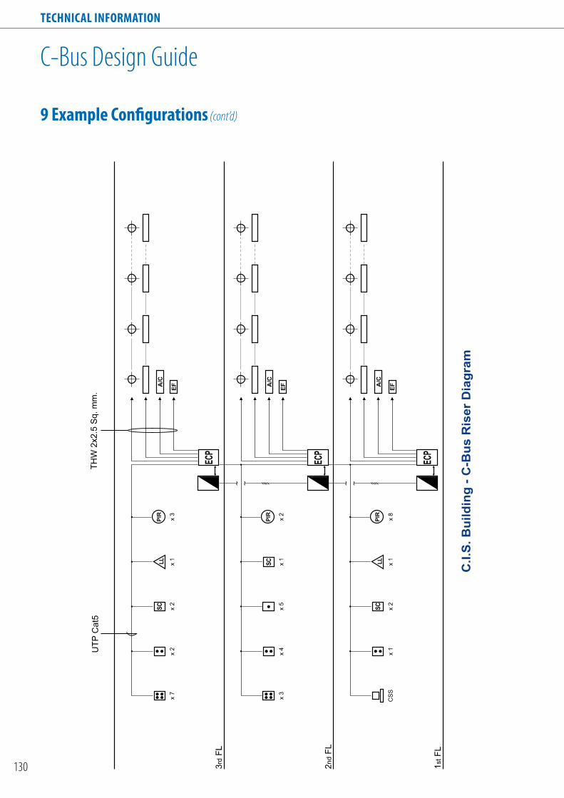
Technical informaTion
130
C-Bus Design Guide
9 example configurations (cont’d)
C.I
.S.
Bu
ild
ing
- C
-Bu
s R
ise
r D
iag
ram
1st F
L
2nd
FL
3rd
FL
A/C
EF
CS
Sx
1
SC x 2
LL x 1
PIR x 8
A/C
EF
x 3
x 4
SC
x 5
x 1
PIR x 2
A/C
EF
ECP
ECP
ECP
x 7
x 2
SC x 2
LL x 1
PIR x 3
UT
P C
at5
TH
W 2
x2.5
Sq.
mm
.

Technical informaTion
131
C-Bus Design Guide
9 example configurations (cont’d)

Technical informaTion
132
C-Bus Design Guide
9 example configurations (cont’d)
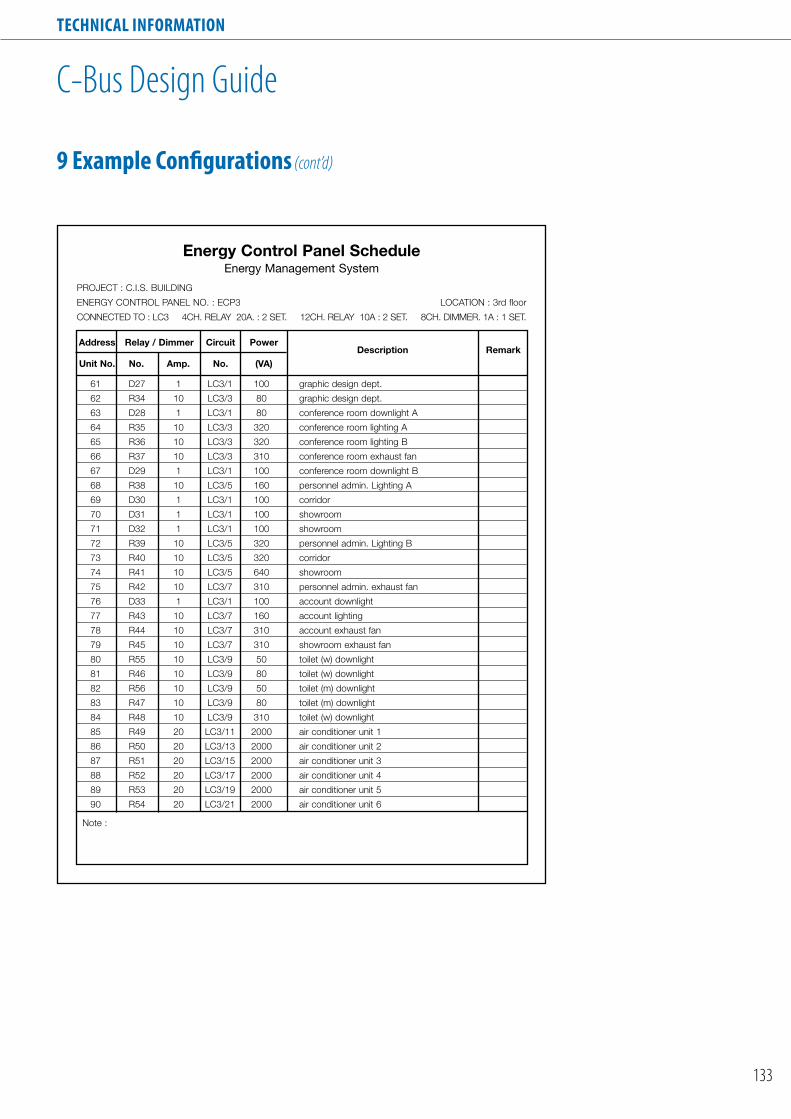
Technical informaTion
133
C-Bus Design Guide
9 example configurations (cont’d)

Technical informaTion
134
C-Bus Design Guide
9 example configurations (cont’d)

Technical informaTion
135
C-Bus Design Guide
Energy Control Panel9 example configurations (cont’d)
energy control Panel
(ecP1)
NE A/L
Unit
C-Bus CONNECTIONS
Dimmer
1 2 3 4 5 6 7 8 A/L N
1 2 3 4
5 6 7 8
C-Bus
NE A/L
Unit
C-Bus CONNECTIONS
Dimmer
1 2 3 4 5 6 7 8 A/L N
1 2 3 4
5 6 7 8
C-Bus
NE A/L
Unit
C-Bus CONNECTIONS
Dimmer
1 2 3 4 5 6 7 8 A/L N
1 2 3 4
5 6 7 8
C-Bus
N A/L
Unit
C-Bus
C-Bus CONNECTIONS
Power Supply
1A 1B 2A 2B 3A 3B 4A 4BNE A/L
C-Bus CONNECTIONS
C-Bus Voltage Free Relay
Unit
OFF OFF OFF OFF
1A 1B 2A 2B 3A 3B 4A 4B 5A 5B 6A 6BNE A/L
C-Bus CONNECTIONS
2 3 4 5
8
1
7
6
129 10 11
C-Bus
7A 7B 8A 8B 9A 9B 10A 10B 11A 11B 12A 12B
Voltage Free Relay
Unit
energy control Panel
(ecP2)
NE A/L
Unit
C-Bus CONNECTIONS
Dimmer
1 2 3 4 5 6 7 8 A/L N
1 2 3 4
5 6 7 8
C-Bus
N A/L
Unit
C-Bus
C-Bus CONNECTIONS
Power Supply
1A 1B 2A 2B 3A 3B 4A 4BNE A/L
C-Bus CONNECTIONS
C-Bus Voltage Free Relay
Unit
OFF OFF OFF OFF
1A 1B 2A 2B 3A 3B 4A 4BNE A/L
C-Bus CONNECTIONS
C-Bus Voltage Free Relay
Unit
OFF OFF OFF OFF
1A 1B 2A 2B 3A 3B 4A 4B 5A 5B 6A 6BNE A/L
C-Bus CONNECTIONS
2 3 4 5
8
1
7
6
129 10 11
C-Bus
7A 7B 8A 8B 9A 9B 10A 10B 11A 11B 12A 12B
Voltage Free Relay
Unit
1A 1B 2A 2B 3A 3B 4A 4B 5A 5B 6A 6BNE A/L
C-Bus CONNECTIONS
2 3 4 5
8
1
7
6
129 10 11
C-Bus
7A 7B 8A 8B 9A 9B 10A 10B 11A 11B 12A 12B
Voltage Free Relay
Unit
energy control Panel
(ecP3)
RS-232
RS
-232Unit/
Comms
C-Bus
C-Bus CONNECTIONS
PC Interface
inside View Side View front View
850
500 500150
216
142
85
65
100
142
Ventilation
All Dimensions in mm. (WxHxD)
TM

Technical informaTion
136
C-Bus Design Guide
9 example configurations (cont’d)
C-Bus Basic Wiring Diagram
Control Room
C-Bus CONNECTIONS
RS-232
1st
FL.
2nd
FL.
Computer
PCI
Central Selector Switch
Or
Touch Screen
Energy Control Panel 1 (ECP1)
Energy Control Panel 2 (ECP2)
to Next Floor
NE A/L
C-Bus CONNECTIONS
1A 1B 2A 2B 3A 3B
7A 7B 8A 8B 9A 9B
4A 4B 5A 5B 6A 6B
10A 10B 11A 11B 12A 12B
Relay Unit
220 Vac
NE A/L
C-Bus CONNECTIONS
1A 1B 2A 2B 3A 3B
7A 7B 8A 8B 9A 9B
4A 4B 5A 5B 6A 6B
10A 10B 11A 11B 12A 12B
Relay Unit
220 Vac
Local Switch
Local Switch
Local Switch
to Control Room
UTP Cat.5(Single Line)
36Vdc
3A 3B
N A/L
C-Bus CONNECTIONS
PowerSupply
220 Vac 220 Vac
NE A/L
C-Bus CONNECTIONS
1 2 3 4 5 6 7 8 A/L N
Dimmer Unit
R S T
Load
Load Center
4CH. Relay20A. Unit
Relay Control byKey Input Unit (SW.)Sensor or Computer
Motion Sensor
Example C-Bus Wiring & Control
1 2 CH1
CH2
CH3
CH4
3 4
5 6
7 8
9 10
N
Key Input Unit
or
NE A/L
C-Bus CONNECTIONS
1A 1B 2A 2B 4A 4B
Relay Unit4 CH. Relay (20A/CH.)
NE A/L
C-Bus CONNECTIONS
1 2 3 4 5 6 7 8 A/L N
Dimmer Unit8 CH. Dimmer
NE A/L
C-Bus CONNECTIONS
1A 1B 2A 2B 3A 3B
7A 7B 8A 8B 9A 9B
4A 4B 5A 5B 6A 6B
10A 10B 11A 11B 12A 12B
Relay Unit12 CH. Relay (10A/CH.)

Technical informaTion
137
C-Bus Design Guide
Integrated Home Automation System9 example configurations (cont’d)
PC Interface5500PC
Touch ScreenSC5000CT
DLT5085DL
240VAC
C-Bus Network / 1000 Meters / 100 Devices
4 Channel VoltageFree Relay (Learn)L5504RVF
240V
AC
Neo KeyInput (Learn)E5058NL
Lig
hti
ng
Co
ntr
ol
/ D
imm
ing
6 Channel Pro SeriesDimmer (Learn)L5106D10LP
240V
AC
Po
wer
Dev
ices
/ A
pp
lian
ces
4 Channel Voltage FreeChangeover Relay (Learn)L5504RVFC
240V
AC
HV
AC
/ M
oto
rise
d B
lind
s &
Sh
utt
ers
Infrared Output Module5034NIRT
Au
dio
Vis
ual
& IR
Eq
uip
men
t
Amplifier & CD Player
Infr
a-re
d E
mitt
er
8050
LD
Tuner 96.1 FM
CD 1 Track 4 3:25
Bus Coupler Input5104BCL
Input Switch
OccupancySensorE5751L
Software RequiredWindows 98SE, XP, ME, 2000C-Bus Toolkit Software - 5000S/3Schneider plus-5000SPXHome Gate-5000DHGX
PC
Inte
rfac
e

Technical informaTion
138
C-Bus Design Guide
Integrated to 3rd Party Media Control Systems - Crestron/AMX/Phast9 example configurations (cont’d)
240VAC
C-Bus Network / 1000 Meters / 100 Devices
Crestron / AMX/ PhastController
4 Channel Pro SeriesDimmer (Learn)L5104D5
PC Interface5500PC Scene Master
5035NIRSL
Power Supply5500PS
4 Channel VoltageFree Relay (Learn)L5504RVF
240V
AC
36V
DC
240V
AC
240V
AC
Neo KeyInput (Learn)E5508NL
RS232
Touch Panel
6 Channel Pre SeriesDimmer
L5106D10LP
DLT5085DL

Technical informaTion
139
C-Bus Learn Units Quick Programming Guide
1. entering learn mode
Hold down a toggle key on any output unit for 10 seconds. Unit and C-Bus indicators on Output Units will flash alternatively.
Note: These two indicators may initially flash together for up to 20 seconds before flashing alternatively.
All loads and indicators will turn off except the one pressed which will turn on.
All indicators on Input Units will turn off.
2. choosing the electrical load to be controlled
Press the toggle key switches on the Output Units which turn on the desired lights. Unit and C-Bus indicators continue to flash alternatively.
The selected lights and indicators are switched on.
3. Selecting the Key input Switches to control the chosen loads3A. Setting Input Keys as On/Off Switches
Press the Key Inputs required to control the selected loads.
The switches required to control the loads will be illuminated.
Exit Learn Mode by pressing any toggle switch on a Relay Output Unit for 2 seconds. C-Bus2 will now Learn the relationship and will return to normal operation.
Units and C-Bus indicators will stop flashing.

Technical informaTion
140
C-Bus Learn Units Quick Programming Guide
Press one key for a single operated dimmer. toggle dimmer
Exit Learn mode by pressing any toggle switch on a Dimmer Output Unit for 2 seconds.
C-Bus2 will now Learn the relationship and will return to normal operation.
Units and C-Bus Indicators will stop flashing.
1
1
22
Press two keys on the same unit for two key operated dimmer. The first key pressed will be an on/up key and the second key pressed will be the off/down button.
oron/up
off/down
on/up
off/down
Hold down a key until the indicator comes on, then release the key.
The key switch will flash at one second intervals.
Note: Exiting Learn Mode at this point will make the key a 5 second timer.
Exit Learn Mode by pressing any toggle switch on a Relay or Dimmer Output Unit for 2 seconds.
C-Bus2 will now Learn the relationship and will return to normal operation.
Units and C-Bus Indicators will stop flashing.
Continuing to hold down the key will cause the indicator to double flash every one second.
Each double flasah represents 5 minutes.
For example, releasing the key after 4 double flashes gives a 20 minute timer.
3. Selecting the Key input Switches to control the chosen loads3B. Setting Input Keys as Dimmer Switches
3C. Setting Input Keys as Timer Switches
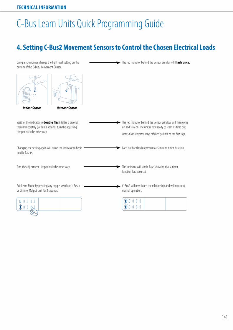
Technical informaTion
141
C-Bus Learn Units Quick Programming Guide
4. Setting c-Bus2 movement Sensors to control the chosen electrical loads
Using a screwdriver, change the light level setting on the bottom of the C-Bus2 Movement Sensor.
Wait for the indicator to double flash (after 5 seconds) then immediately (within 1 second) turn the adjusting trimpot back the other way.
The red indicator behind the Sensor Window will then come on and stay on. The unit is now ready to learn its time out.
Note: If the indicator stays off then go back to the first step.
Changing the setting again will cause the indicator to begin double flashes.
Exit Learn Mode by pressing any toggle switch on a Relay or Dimmer Output Unit for 2 seconds.
C-Bus2 will now Learn the relationship and will return to normal operation.
Each double flasah represents a 5 minute timer duration.
The red indicator behind the Sensor Windor will flash once.
Indoor Sensor Outdoor Sensor
Turn the adjustment trimpot back the other way. The indicator will single flash showing that a timer function has been set.

A new world of colour is at your fingertips. The flushmounted colour touch screen is fully customisableand gives you the ultimate control of any sceneor device connected to a C-Bus home/building automation system. Everything else willsoon be turning red, blue and green with envy!
Red, blue and green with envy.

SE01
8-02
09-0
0
Clipsal is a registered trademark of the Schneider Electric Group
About Schneider Electric
Listed in Paris as a CAC 40 company, Schneider Electric is a leading global specialist in energy management offering integrated solutions that makes energy safer, more reliable, efficient and productive in the energy & infrastructure, industry, data centres & networks, buildings and residential markets. With sales of 17.3 billion euro in 2007, the company’s 120,000 employees in 102 countries help individuals & organisations make the most of their energy.
Our Installation Systems & Control Division provides solutions that represent the best in lifestyle and innovation for offices, hotels and homes. Specific examples include award-winning products and technologies covering building and home automation, structured cabling, and designer switches and sockets.
About Clipsal
Clipsal was established in Adelaide, Australia in 1920. Since then, it has grown from an innovator of electrical accessories to a leader in integrated control automation, structured cabling and energy conservation products in addition to electrical accessories.
Clipsal has become a member of the Schneider Electric Group since 2003.


![2012 Race 1 V8 Supercars Clipsal 500 Adelaide [Adelaide Clipsal]](https://img.dokumen.tips/doc/110x75/55c65bb9bb61eb884d8b482a/2012-race-1-v8-supercars-clipsal-500-adelaide-adelaide-clipsal.jpg)