Embed Size (px)
Citation preview
1
1
Wired and Wireless Sensor Networks for
Bridge Health Monitoring
Paul I. Lin, MengWei Li, Bob Tilbury, Max Yen, and
Dong Chen
College of Engineering, Technology, and Computer Science
Indiana University-Purdue University Fort Wayne
Room ET 346
April 22, 2014
2
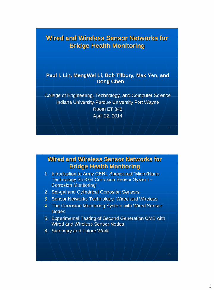
Wired and Wireless Sensor Networks for
Bridge Health Monitoring
1. Introduction to Army CERL Sponsored “Micro/Nano
Technology Sol-Gel Corrosion Sensor System –
Corrosion Monitoring”
2. Sol-gel and Cylindrical Corrosion Sensors
3. Sensor Networks Technology: Wired and Wireless
4. The Corrosion Monitoring System with Wired Sensor
Nodes
5. Experimental Testing of Second Generation CMS with
Wired and Wireless Sensor Nodes
6. Summary and Future Work

2
3
Introduction
The project: “Micro-Nano Technology Sol-Gel
Corrosion Monitoring System,” 2011-2013
• Project sponsor: Army Construction Engineering
Research Laboratory, IL: Richard Lampo and Michael
McInerney
• Project Team
Principal Investigator: Max S. Yen
Co-Pis: Paul I-Hai Lin and Dong Chen
Graduate Students: MengWei Li, Robert Tilbury,
Muhammad Shoaib Mansur
Undergraduate EE Student: Steve Groff
IEEE Indianapolis Conference Nov. 8, 2013
4
Introduction (continue)
The Accomplishments1) “Examination of Corrosion on Steel Structures by Innovative
Nano Sol-Gel Sensors,” by Max Yen, Dong Chen, Paul Lin,
Bakul Dave, Steve Groff, Emily Hauter, Richard Lampo, and
Michael McInerney, NCAE 2012 Corrosion Conference, to be
held on March 11-15, 2012, Salt Lake City, Utah
2) “Corrosion Sensor for Monitoring Early-Stage Environmental
Corrosion of Steel Structure,” Dong Chen, Max yen, and Paul
Lin, U.S. Provisional Patten Application #61763523, Feb. 2013
3) “Micro-Nano Technology Sol-Gen Corrosion Monitoring
System,” New Tech Showcase Demo & Presentation, Indiana
University-Purdue University Fort Wayne, April 24, 2013.
4) “A Corrosion Monitoring System for Early-Stage Warming of
Environmental Corrosion of Structures and Infrastructures,”
Technology Showcase, at 2013 Taipei International Invention
Show & Technomart, Sept. 26-29, 2013.
3
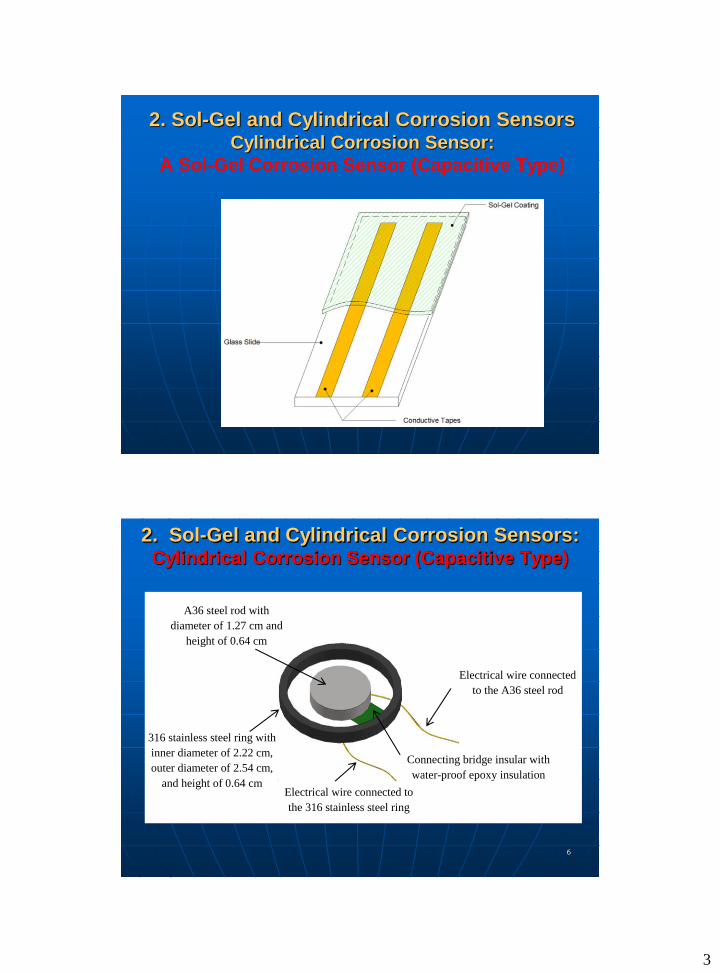
2. Sol-Gel and Cylindrical Corrosion SensorsCylindrical Corrosion Sensor:
A Sol-Gel Corrosion Sensor (Capacitive Type)
6
2. Sol-Gel and Cylindrical Corrosion Sensors: Cylindrical Corrosion Sensor (Capacitive Type)
A36 steel rod with
diameter of 1.27 cm and
height of 0.64 cm
316 stainless steel ring with
inner diameter of 2.22 cm,
outer diameter of 2.54 cm,
and height of 0.64 cm
Connecting bridge insular with
water-proof epoxy insulation
Electrical wire connected
to the A36 steel rod
Electrical wire connected to
the 316 stainless steel ring

4
7
3. Sensor Network Technology: Wired and
Wireless
Definition of Sensor Network
• An infrastructure includes sensing, computing, and
communication elements to provide the ability to instrument,
observe and react to events and phenomena in a specific
environment [1].
• Communication Element: Wired/Wireless
Physical Signal Sources
• Electromagnetic radiation signals: radio and light
• Optical, acoustic , seismic, acceleration, strain, vibration signals
• Chemical and biochemical signals
• Environmental signals: light, temperature, humidity, barometric
8
3. Sensor Network: Wired and Wireless
Wireless Sensor Network (WSN) Applications
• Industrial Monitoring, Control, Automation;
• Building Automation
• Home Automation and Consumer Electronics
• Security and Military Sensing
• Asset Tracking and Supply Chain Management
• Intelligent Agriculture and Environmental Sensing
• Health and Medical Monitoring
• Critical Infrastructure Monitoring, Protection and Security
5
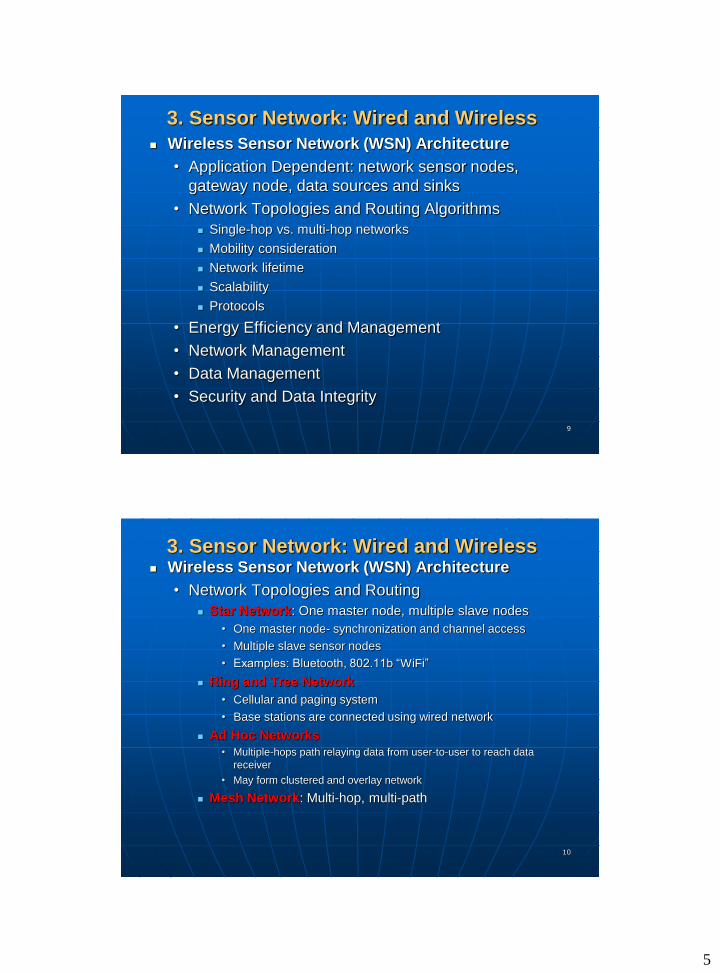
9
3. Sensor Network: Wired and Wireless
Wireless Sensor Network (WSN) Architecture
• Application Dependent: network sensor nodes,
gateway node, data sources and sinks
• Network Topologies and Routing Algorithms
Single-hop vs. multi-hop networks
Mobility consideration
Network lifetime
Scalability
Protocols
• Energy Efficiency and Management
• Network Management
• Data Management
• Security and Data Integrity
10
3. Sensor Network: Wired and Wireless Wireless Sensor Network (WSN) Architecture
• Network Topologies and Routing
Star Network: One master node, multiple slave nodes
• One master node- synchronization and channel access
• Multiple slave sensor nodes
• Examples: Bluetooth, 802.11b “WiFi”
Ring and Tree Network
• Cellular and paging system
• Base stations are connected using wired network
Ad Hoc Networks
• Multiple-hops path relaying data from user-to-user to reach data
receiver
• May form clustered and overlay network
Mesh Network: Multi-hop, multi-path

6
11
3. Sensor Network: Wired and Wireless
Sensor Node Platform Selection Criteria
• Hardware:
• Software:
• Programming Language Tools
• Industrial Standard
• Protocols
• Other Features
12
3. Sensor Network: Wired and Wireless
Sensor Node Platforms
• Microcontroller: TI MSP430-based, Atmel ATmega, IntelPXA255, etc
• Memory: Program and Data
• Interface (USB/Serial/WiFi/Ethernet)
• ADC and Digital I/O
• Transceiver (802.14.4-compliant, others)
XBee
TI CC2420
• Wireless Communication
License-free frequencies
433, 868-915 MHz, and2.4 GHz

7
13
3. Sensor Network: Wired and Wireless
Commercially Available SNA Nodes (www.memsic.com)
TelosB Cricket
IRIS node MICAz/MICA2
14
4. Corrosion Monitoring Sensor System: System Architecture I with Wireless Sensor Node

8
15
4.1 Remote Corrosion Sensor Node
Design
16
4.2 Remote Corrosion Sensor Node
(Power Source Subsystem)
Solar power panel and control (20 W)
DC battery power source (12 V 37 AH)
Power Source Requirement (~ 5 W)
• Sol-Gel sensor bias AC signal source
(sine wave)
• RF power source requirement estimation
(1 W)
• Sol-gel sensor power requirement (1 W)
• Analog signal processing unit power
requirement (0.5 W)
• Digital signal processor (0.5 W)

9
17
4.3 Corrosion Monitoring Sensor System: System Architecture II with Wired Star Topology using
RS 485 Serial Communication
RS-485 Daisy
Chain Link
RS-485-1
RS-232
Industrial Fanless
PC
Windows XP-
embedded
Ethernet/
RJ45Internet
Gateway
CMS
Programs/
Scripts
Sensor Data
Storage
AC 1 kHz Source
Sol-gelCorrosion
Sensor
Analog Signal
Processing Unit
Built-InSystem Program
Corrosion Sensor Connected through RS-485-based DAQ Unit No. 6
Power supply
Corrosion Sensor DAQ Unit No. 2…………………..
Corrosion Sensor DAQ Unit No. 5
ADAM-4016 RS-485 DAQ Node
16-bit A/D x 1
Digital Output x
2
AC 1 kHz Source
Sol-gelCorrosion
Sensor
Analog Signal
Processing Unit
Built-InSystem Program
16-bit A/D x 1
Digital Output x
2
ADAM-4016 RS-485 DAQ Node
Corrosion Sensor Connected through RS-485-based DAQ Unit No. 1
Power supply
Address #1
Address #2
Address #3
Address #6
RS-485 Daisy
Chain Link
18
4.5 Corrosion Monitoring System – Base
Station Faneless Industrial Computer
• HTTP Web server
• FTP file server
• Sensor data storage
• Server scripts/programs
• Data manipulation programs
Internet Gateway
• Remote system
• Web client
USB – WiFi wireless adapter
RS 485, 232 Serial interface

10
19
4.5 Corrosion Monitoring Sensor System(continue)
Corrosion Monitoring Sensor System (CMS)
a) Power supply system
b) The Central Monitoring Computer (CMC)
Fanless Embedded Computer, Windows XP OS setup and
networking option configuration
RS485 serial communication: CMS to Sensor Nodes
Ethernet Ports for Internet communication
c) Thermal Electric Cooler: mounted on the front-side of the CMC
d) Six RS485-based Sensor Nodes with 16-bit ADC
e) Packaging and Cabling
f) Software for Polling Sensor Data Processing and Storage
20
4.4 Analog Signal Processing Circuit and
Fabrication of Printed Circuit Boards
Analog Signal Processing (ASP)
Sin Wave Generator (5V Pk- Pk)
Capacitance to Voltage Conversion
Precision Full-Wave Rectifier
Signal Amplifier & Processing
Noise FilterLoading
Effect BufferADAM 4016 16-bit DAC
CMS

11
21
4.6. Analog Signal Processing Circuit and
Fabrication of Printed Circuit Boards
Fabricated PCB Boards and ADMA 4016 ADC
22
4.7 Corrosion Sensor Modules (Boxes)
Corrosion Sensor Modules (Boxes):
a) Power supply
b) RS-485 communication
c) Microcomputer with 16-bit ADC (analog-to-digital conversion)
d) Sensor Box Packaging with Sensor’s analog signal processing
PCB
e) Cabling
Vin +
Vin -
PCB OUT -
Pin 1: GroundPin 2: Power +22V Pin 3: Power -22V Pin 4: GroundPin 5: Power +22V
PCB OUT +
Watertight Box
5 PIN connector
PCB
PX0739/P 6 poles plug, screw termination
Cat 6 Cable: 4 pair twisted wires
12
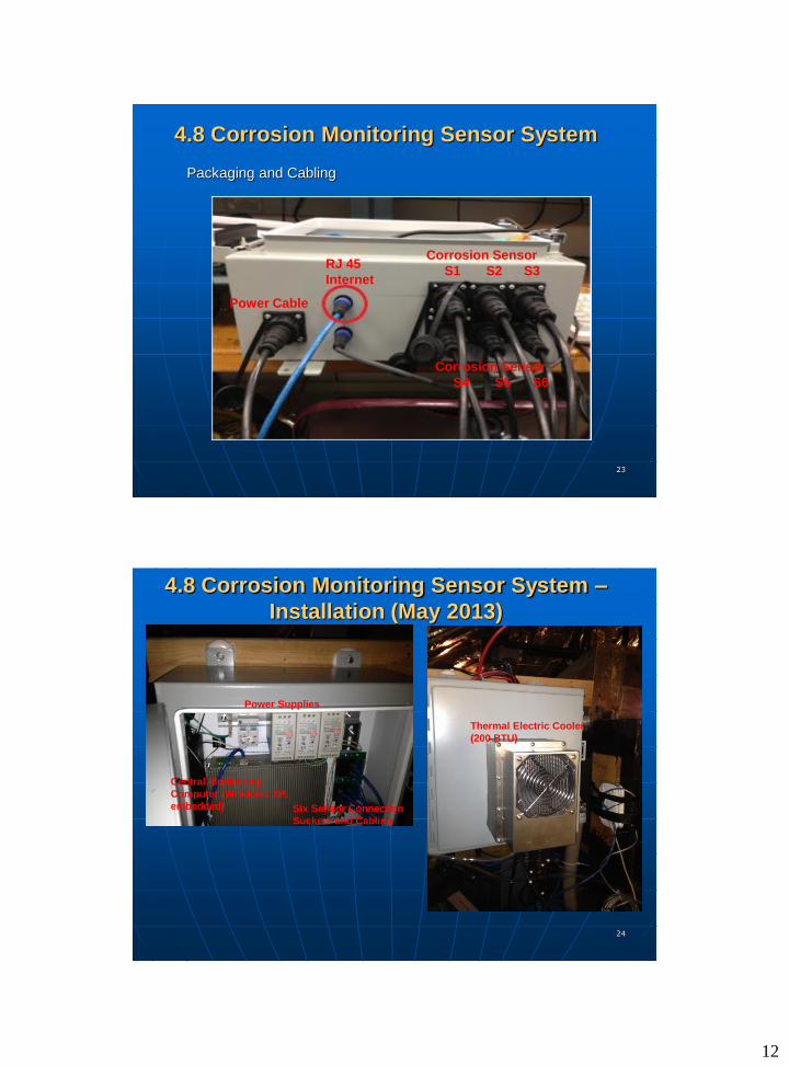
23
4.8 Corrosion Monitoring Sensor System
Packaging and Cabling
Corrosion Sensor
S1 S2 S3
Corrosion Sensor
S4 S5 S6
RJ 45
Internet
Power Cable
24
4.8 Corrosion Monitoring Sensor System –
Installation (May 2013)
Thermal Electric Cooler
(200 BTU)
Central Monitoring
Computer (Windows XP,
embedded)
Power Supplies
Six Sensor Connection
Suckets and Cabling
13
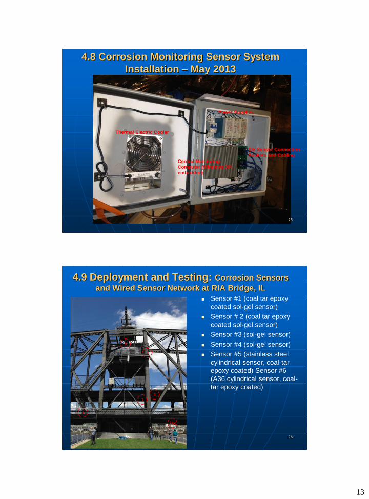
25
4.8 Corrosion Monitoring Sensor System
Installation – May 2013
Central Monitoring
Computer (Windows XP,
embedded)
Six Sensor Connection
Sockets and Cabling
Thermal Electric Cooler
Power Supplies
26
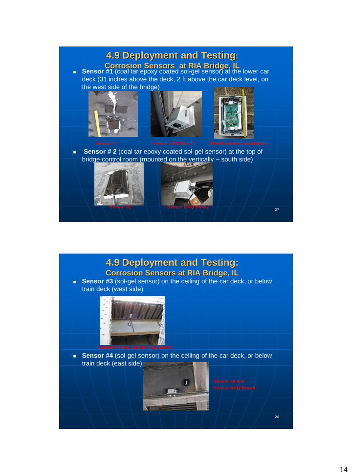
4.9 Deployment and Testing: Corrosion Sensors
and Wired Sensor Network at RIA Bridge, IL
Sensor #1 (coal tar epoxy
coated sol-gel sensor)
Sensor # 2 (coal tar epoxy
coated sol-gel sensor)
Sensor #3 (sol-gel sensor)
Sensor #4 (sol-gel sensor)
Sensor #5 (stainless steel
cylindrical sensor, coal-tar
epoxy coated) Sensor #6
(A36 cylindrical sensor, coal-
tar epoxy coated)
5&6
4
3
1
2
R
14
27
4.9 Deployment and Testing:
Corrosion Sensors at RIA Bridge, IL Sensor #1 (coal tar epoxy coated sol-gel sensor) at the lower car
deck (31 inches above the deck, 2 ft above the car deck level, on
the west side of the bridge)
Sensor #1 Sensor DAQ Box #1 Box#1 (before installation)
Sensor # 2 (coal tar epoxy coated sol-gel sensor) at the top of
bridge control room (mounted on the vertically – south side)
Sensor #2 Sensor DAQ Box#2
28
4.9 Deployment and Testing:Corrosion Sensors at RIA Bridge, IL
Sensor #3 (sol-gel sensor) on the ceiling of the car deck, or below
train deck (west side)
Sensor #3 and Sensor DAQ Box#3
Sensor #4 (sol-gel sensor) on the ceiling of the car deck, or below
train deck (east side)
Sensor #4 and
Sensor DAQ Box#4

15
29
4.9 Deployment and Testing:Corrosion Sensors at RIA Bridge, IL
Sensor #5 Cylindrical Sensor (316 stainless steel cylindrical rod
and ring, coal-tar epoxy coated) under the car deck (west side)
Sensor #5 and Sensor DAQ Box#5
30
4.9 Deployment and Testing:
Corrosion Sensors at RIA Bridge, IL Sensor #6 Cylindrical Sensor (A36 cylindrical rod sensor, stainless
steel outer ring, coal-tar epoxy coated) under the car deck (east
side).

16
31
4.10 Testing of CMS with Sensor Nodes and
Wired Sensor Network, RIA Bridge, IL
Initial Testing of Deployed Sensors using ADAM Utility & Spraying Water
on Sensors
32
4.11 CMS Networking and Communication
Subsystem
Arsenal Bridge Control Tower
ARMY CorrosionMonitoring Sever
Computer
INTERNET
SmartPhone
Laptop
Arsenal Bridge, Rock Island, IL
Current Connection Setup
Sprint Cell Tower
Internet on the Go 3G Mobile Hot Spot
(Sprint)
NENTGEAR N300 Wireless-N
USB Adapter
3G Signal
WIFI Signal
Internet on the Go 3G Mobile Hot Spot
(Sprint)
TP-LINKWireless-N
USB Adapter
Redundant WiFi Hotspots and LAN Adapters

17
33
4.12 Redundant WiFi Hotspots and USB LAN
Adapter
1st WiFi HotSpot 2nd WiFi HotSpot
2 WiFi HotSpot Computer
Side Wireless LAN Adapter
Cooling
Fan &
Thermal
Stat
34
4.13 Corrosion Monitoring Sensor System
Server Scripts/Programs
CMS sensor data polling program
• Every 30 minute, read sensors capacitance/volatge
value: S1,… S6
• Add time stamps
• Store sensor data S1, … S6
Sensor node control, data access
Remote access to the CMS through a secured web
client
• Cloud storage service: DropBox
• Cloud-based remote access - LogMeIn

18
35
4.14 Sensor Data and Remote Data
Collection
a) Data Collection and Storage
• Data saved (every 30 minutes) at the CMS system
located at RIA bridge
b) Cloud-based Remote Access: LogMeIn
c) Move data to Cloud-based Data Store: Drop Box
36
5. The Second Generation CMS System: Wired & Wireless Sensor Nodes and Networks
Improved Internet and remote CMS system accessibility with at least
one dedicated static IP address to provide better remote system
access and maintenance support.
Addition of Wireless Sensor Nodes and Networks to enhance the
system reliability
Additional local temperature and humidity data collection
19
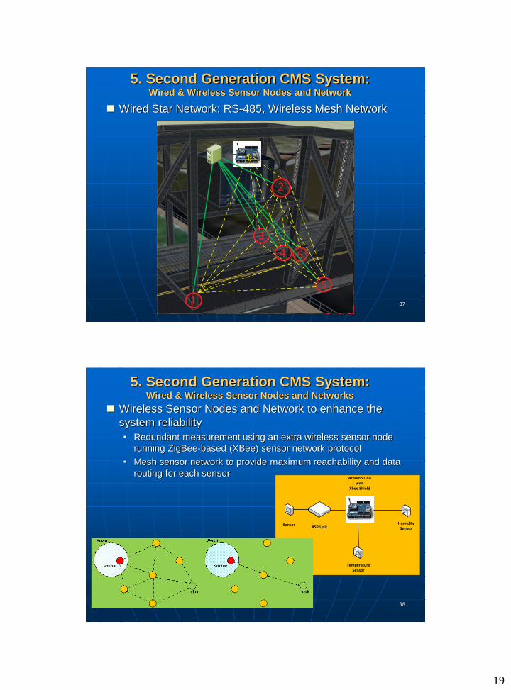
37
5. Second Generation CMS System:Wired & Wireless Sensor Nodes and Network
Wired Star Network: RS-485, Wireless Mesh Network
38
5. Second Generation CMS System:Wired & Wireless Sensor Nodes and Networks
Wireless Sensor Nodes and Network to enhance the
system reliability
• Redundant measurement using an extra wireless sensor node
running ZigBee-based (XBee) sensor network protocol
• Mesh sensor network to provide maximum reachability and data
routing for each sensor
SensorASP Unit
Arduino Uno with
Xbee Shield
Temperature Sensor
Humidity Sensor

20
39
5. Second Generation CMS System:Wired & Wireless Sensor Nodes and Networks
Wireless Sensor Nodes and Networks to enhance the
system reliability
Sensor ASP Unit Receiver (Coordinator)
CMSServer
Connected and powered
Via USB
Mesh Wireless ZigBee
Sensor 1
Transmitter
ADAM-4016DAQ
Sensor ASP Unit
Arduino Uno with Xbee Shield
ADAM-4016DAQ
Sensor 6
RS-485
COM 3
Arduino Uno with Xbee Shield
Transmitter
.
.
40
5. Second Generation CMS System:Wired & Wireless Sensor Nodes and Networks
Experimental Testing of Wireless Sensor Nodes and
Networks in M.S. Tech Graduate Research Lab
21
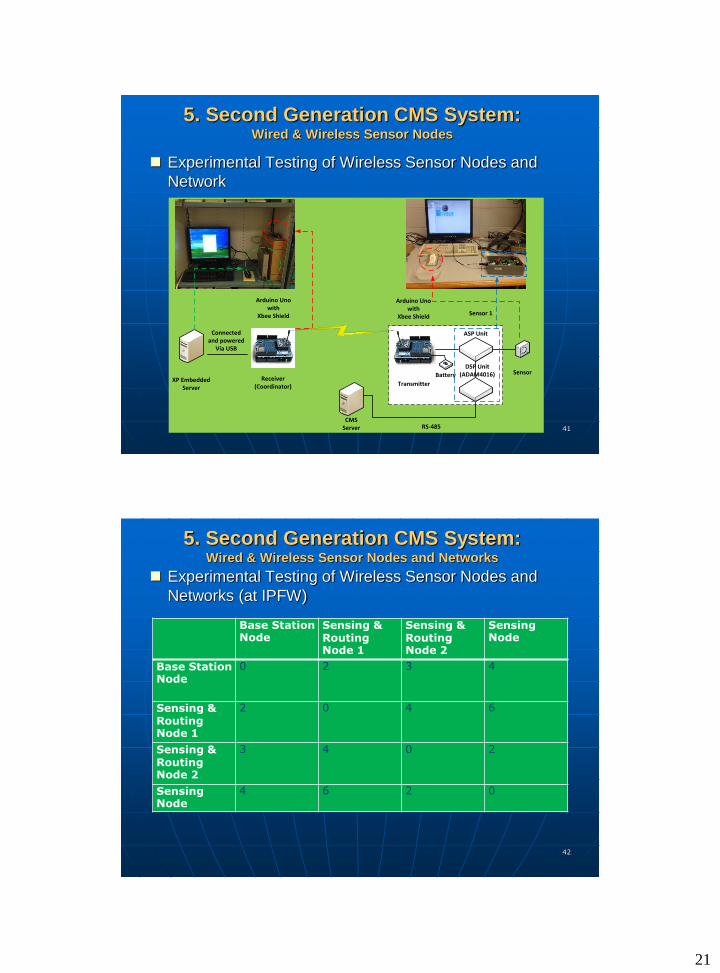
41
5. Second Generation CMS System:Wired & Wireless Sensor Nodes
Experimental Testing of Wireless Sensor Nodes and
Network
Arduino Uno with
Xbee Shield
Receiver (Coordinator)
XP EmbeddedServer
Connected and powered
Via USB
Sensor
ASP Unit
Arduino Uno with
Xbee Shield
Transmitter
Sensor 1
Battery
CMSServer RS-485
DSP Unit (ADAM4016)
42
5. Second Generation CMS System:Wired & Wireless Sensor Nodes and Networks
Experimental Testing of Wireless Sensor Nodes and
Networks (at IPFW)
Base Station Node
Sensing & Routing Node 1
Sensing & Routing Node 2
Sensing Node
Base Station Node
0 2 3 4
Sensing & Routing Node 1
2 0 4 6
Sensing & Routing Node 2
3 4 0 2
Sensing Node
4 6 2 0

22
43
5. Second Generation CMS System:Wired & Wireless Sensor Nodes and Networks
Experimental Testing of Wireless Sensor Nodes and
Networks to enhance the system reliability (4 nodes)
4
3
2
24
6
Sensing Node
Sensing & Routing Node 2
Sensing & Routing Node 1
Base Station Node (Coordinator)
44
5. Second Generation CMS System:Wired & Wireless Sensor Nodes and Networks
Experimental Testing of Wireless Sensor Nodes and
Networks to enhance the system reliability (4 nodes)
IPFW ETCS Building
LOBBY
3F
2F
1F
50 FEET
100 FEET
133 FEET
30 FEET
Sensing Node
Sensing & Routing Node 2
Sensing & Routing Node 1
Base Station Node (Coordinator)
Outdoor

23
45
5. Second Generation CMS System:Wired & Wireless Sensor Nodes and Networks
Experimental Testing of Four Wireless Sensor Nodes
and Network
50 FEET
100 FEET
133 FEET
30 FEET
Base Station node (Coordintor)
Sensing & Routing node 1
Sensing & Routing node 2Sensing node
46
6. Summary and Future Work
The star-based wired sensor network for Army Bridge’s
Corrosion Monitoring System deployed at RIA, IL has
been running since May 2013
Wires and wireless sensors version of the CMS has
been discussed at CERL, IL on April 14, 2014
Redesign new wireless sensor node which integrates the
following modules and features (Luis Morale’s Master of
Science Directed Project, Spring 2014)
• A new PCB board (surface mount)
• Analog Signal Processing Subsystem – corrosion sensing
• Xbee (Zigbee based transceiver with antenna)
• Temperature, humidity, and barometric pressure sensing
• Adurino Fio versions 2 and 3

24
47
Conclusion
Any Questions?
Thank you!!!
![REMOTE CONTROLLER (WIRED TYPE) - Планета Климата · REMOTE CONTROLLER (WIRED TYPE) [Original instructions] OPERATING MANUAL WIRED REMOTE CONTROLLER Keep this manual](https://img.dokumen.tips/doc/110x75/5c9f331488c993502d8ceaa7/remote-controller-wired-type-remote-controller.jpg)