Embed Size (px)
Citation preview

Release v2014.0November 18, 2014L1-0: 1 © 2014 ANSYS, Inc.
v2014.0 Release
Modern Simulation Solutions for Signal
and Power Integrity for Efficient Design
of PCBs
Peter Krenz, Application Engineer
Release v2014.0November 18, 2014L1-0: 2 © 2014 ANSYS, Inc.
Agenda
• Introduction
– High Frequency Simulation Tools Overview
– Cannel Simulation Flow
• SIwave Capabilities
• Test case:
– Decoupling Capacitor Optimization
– PCI Express 8 GT/s Channel
• Summary

Release v2014.0November 18, 2014L1-0: 3 © 2014 ANSYS, Inc.
ANSYS:
High Frequency Applications Overview

Release v2014.0November 18, 2014L1-0: 4 © 2014 ANSYS, Inc.
What is HFSS?
• Premier 3D Electromagnetic
design tool
• Solves
– Any arbitrary 3D structure
• Uses
– Full Wave Finite Element Method (FEM)
– Transient Finite Element Solver
– Integral Equation Solver
– Physical Optics Solver

Release v2014.0November 18, 2014L1-0: 5 © 2014 ANSYS, Inc.
What is SIwave?
• ANSYS SIwave evaluates designs from entire package, board, or
package on board
• SIwave includes all effects of coupling between traces, packages,
and board
– Advanced Signal- and Power-Integrity Analysis
– Easy Layout Extraction (S,Y,Z)
– Automated Decoupling Capacitor Optimization
– Integrated and Automated DC I²R Reporting
– Advanced Broadband SPICE Model Generation
– Highly Accurate Macro Modeling
– High-Performance Computing
– Comprehensive Multi-physics (Icepak)
Release v2014.0November 18, 2014L1-0: 6 © 2014 ANSYS, Inc.
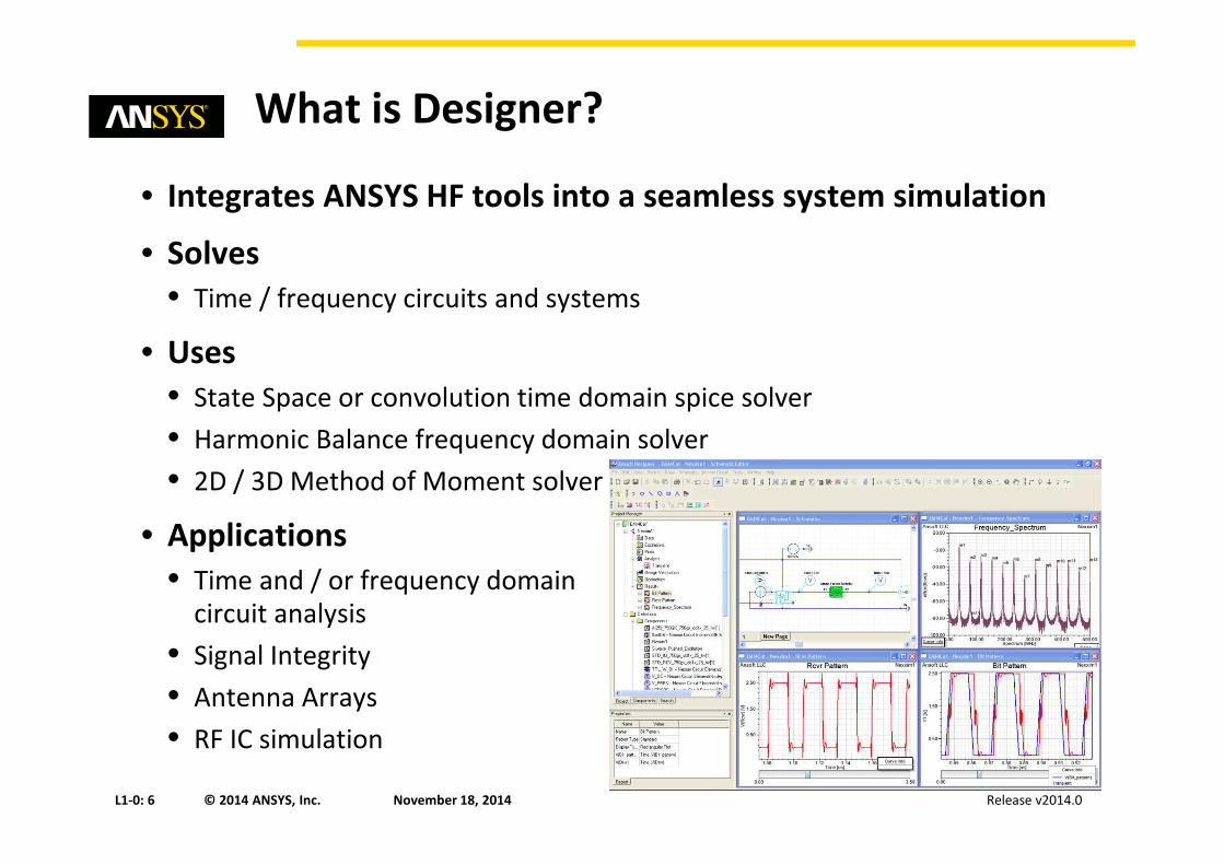
What is Designer?
• Integrates ANSYS HF tools into a seamless system simulation
• Solves
• Time / frequency circuits and systems
• Uses
• State Space or convolution time domain spice solver
• Harmonic Balance frequency domain solver
• 2D / 3D Method of Moment solver
• Applications
• Time and / or frequency domain circuit analysis
• Signal Integrity
• Antenna Arrays
• RF IC simulation

Release v2014.0November 18, 2014L1-0: 7 © 2014 ANSYS, Inc.
SIwave:
Channel Simulation Flow

Release v2014.0November 18, 2014L1-0: 8 © 2014 ANSYS, Inc.
Introduction: Channel Simulation Flow
Post layout validation -> Simulate the physical architectures, create electromagnetic-
based models, and apply time domain signaling in conjunction with these models.
ANSYS has streamlined this process for engineers with the use of one product: SIwave
Cadence•Allegro
•APD/SiP•Virtuoso
Mentor
Zuken
Altium
SIwave
DesignerSI Circuit
Q3D
HFSS
ANF/ODB++
EDAD DB

Release v2014.0November 18, 2014L1-0: 9 © 2014 ANSYS, Inc. 0.00 2.00 4.00 6.00 8.00 10.00F [GHz]
-100.00
-90.00
-80.00
-70.00
-60.00
-50.00
-40.00
-30.00
Y1
Circuit1FEXT
Curve Info40mil Spacing
LinearFrequency12mil Spacing
LinearFrequency
Introduction
• A pass/fail solution quickly shows engineers if their design is sufficient or not.
• ANSYS Solution Gold Standard Accuracy with Parasitic Extraction
• Each component of the channel can be decomposed, studied, and optimized
• This solution provides the Why

Release v2014.0November 18, 2014L1-0: 10 © 2014 ANSYS, Inc.
SIwave:
Power and Signal Integrity Extractor

Release v2014.0November 18, 2014L1-0: 11 © 2014 ANSYS, Inc.
What is SIwave?
• ANSYS SIwave evaluates designs from entire package, board, or
package on board
• SIwave includes all effects of coupling between traces, packages,
and board
– Advanced Signal- and Power-Integrity Analysis
– Easy Layout Extraction (S,Y,Z)
– Automated Decoupling Capacitor Optimization
– Integrated and Automated DC I²R Reporting
– Advanced Broadband SPICE Model Generation
– Highly Accurate Macro Modeling
– High-Performance Computing
– Comprehensive Multi-physics (Icepak)

Release v2014.0November 18, 2014L1-0: 12 © 2014 ANSYS, Inc.
SIwave: More Than 2.5D
• SIwave 2.5D Full wave Hybrid solver
• SIwave 2.5D Full wave Hybrid solver + Q3d
• HFSS 3D Full Wave FEM

Release v2014.0November 18, 2014L1-0: 13 © 2014 ANSYS, Inc.
Full-Wave Package/Board Positioning
Hybrid
Board + Package
SIwave
SI/PI• FAST Hybrid method for PKG/BRD
• Marked ease of interaction with
Complicated Board geometries
• Handles many, but not all 3D effects
Fast
Arbitrary 3D
Arbitrary 3D Electromagnetics
HFSS-Solver on Demand
SI• Golden Accuracy Simulator
• Solves Any 3D geometry
• Powerful for Critical Nets
• Layout Front-end for HFSS
Any Geometry
Gold Standard Accuracy
SPEED

Release v2014.0November 18, 2014L1-0: 14 © 2014 ANSYS, Inc.
SIwave Includes Alinks for EDA

Release v2014.0November 18, 2014L1-0: 15 © 2014 ANSYS, Inc.
SIwave:
NEW DesignerSI Circuit Capability

Release v2014.0November 18, 2014L1-0: 16 © 2014 ANSYS, Inc.
Designer for SI
• Circuit Simulator- Nexxim Engine (transient, fast convolution, statistical and IBIS-AMI circuit simulation)
• Integrated Schematic capture and layout tool
• Design management front-end linking EM simulation products (HFSS, Q3D, SIwave, ..)
• 2D quasi-static field solver
• HFSS Solver on Demand
Release v2014.0November 18, 2014L1-0: 17 © 2014 ANSYS, Inc.
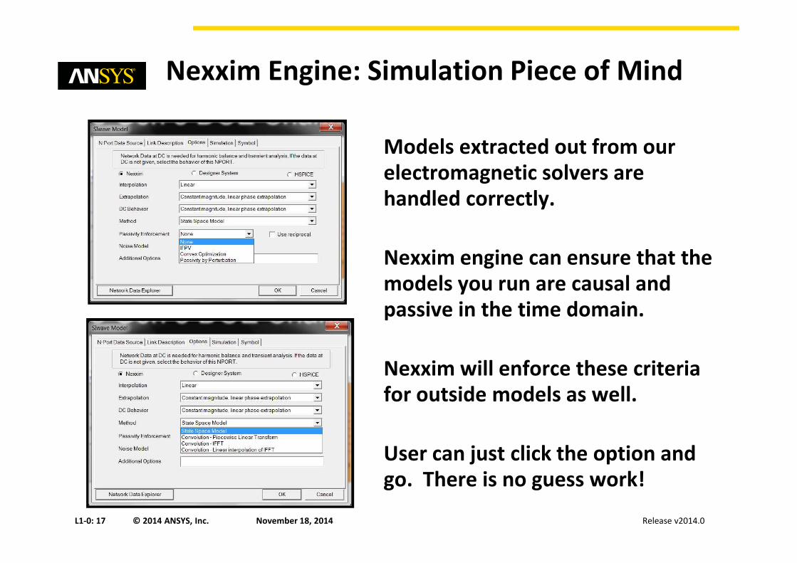
Nexxim Engine: Simulation Piece of Mind
Models extracted out from our
electromagnetic solvers are
handled correctly.
Nexxim engine can ensure that the
models you run are causal and
passive in the time domain.
Nexxim will enforce these criteria
for outside models as well.
User can just click the option and
go. There is no guess work!
Release v2014.0November 18, 2014L1-0: 18 © 2014 ANSYS, Inc.
What is ANSYS UDO?
• UDO (User Defined Outputs) allows calculations and
post-processing of use raw transient simulation data
– Designer SDF file
– H-Spice TR0 file
• Key benefits:
– Non-Ideal voltage supply is supported
– Every bit-by-bit falling and rising transition edge is calculated
– Fully customizable through Python scripts.
• UDOs specific to LPDDR, DDR2 and DDR3 standards already exist!

Release v2014.0November 18, 2014L1-0: 19 © 2014 ANSYS, Inc.
What is an ANSYS UDO?

Release v2014.0November 18, 2014L1-0: 20 © 2014 ANSYS, Inc.
What is an ANSYS UDD?
• Example of a potential report created in PDF and HTML
format

Release v2014.0November 18, 2014L1-0: 21 © 2014 ANSYS, Inc.
SIwave:
Decoupling Capacitor Optimization

Release v2014.0November 18, 2014L1-0: 22 © 2014 ANSYS, Inc.
Power Integrity Investigation
Bare Board
Board w/ Bulk Caps
Target impedance
800 mΩ

Release v2014.0November 18, 2014L1-0: 23 © 2014 ANSYS, Inc.
Power Integrity Investigation
U41

Release v2014.0November 18, 2014L1-0: 24 © 2014 ANSYS, Inc.
Investigate Available Decoupling Capacitors
Capacitor Library Browser1. More than 20,000 Cap & Inductor models included
2. Enables viewing multiple capacitor impedances
curves
3. Calculates parallel impedance of multiple Caps
4. Enables creation of Customer Defined Libraries
5. Allows user defined filtering to narrow down
capacitor selection

Release v2014.0November 18, 2014L1-0: 25 © 2014 ANSYS, Inc.
Automated Process to Optimize Capacitors
• Genetic Algorithm Setup
– Optimized for Impedance
– Optimized for Total Number of Capacitors
– Optimized for Capacitor Types
– Optimized for Price
Release v2014.0November 18, 2014L1-0: 26 © 2014 ANSYS, Inc.
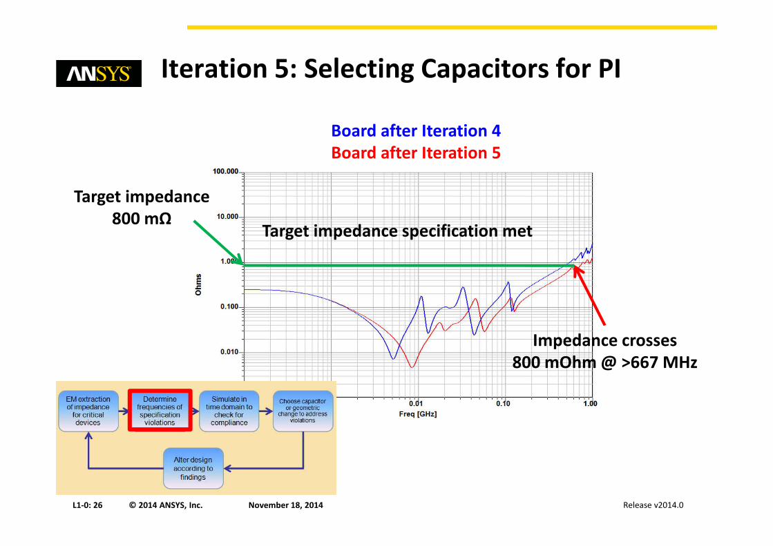
Iteration 5: Selecting Capacitors for PI
Impedance crosses
800 mOhm @ >667 MHz
Board after Iteration 4
Board after Iteration 5
Target impedance specification met
Target impedance
800 mΩ

Release v2014.0November 18, 2014L1-0: 27 © 2014 ANSYS, Inc.
0.00 10.00 20.00 30.00 40.00 50.00 60.00 70.00 80.00 90.00 100.00Time [ns]
1.20
1.40
1.60
1.80
2.00
2.20
2.40
Y1
[V]
Ansoft Corporation BuriedU41 Power
Curve Info pk2pk
V(VCC_U41-2)Transient
0.2177
V(VCC_U41-21)Transient
0.2295
V(VCC_U41-42)Transient
0.2418
V(VCC_U41-44)Transient
0.2549
V(VCC_U41-63)Transient
0.2729
V(VCC_U41-84)Transient
0.2169
Iteration 5
Maximum peak to peak noise 273 mV
24% smaller than limit
Shaded area represents time domain
specification 1.8 V ± 10%
Time-domain noise specification met
3Meter FF

Release v2014.0November 18, 2014L1-0: 28 © 2014 ANSYS, Inc.
PI Advisor: Automated PI Analysis
• Optimizes Decoupling Capacitors
for Power Integrity
• Time = 15 min 7 sec
– Frequency Setup
• 1KHz <= f < 1GHz
• Original solution
– Total # Caps: 74
• Optimized Solution
– Total # Caps: 18
– Capacitor Types = 5
• AVX, Samsung, and Kemet
Capacitor Loop
Inductance Plot

Release v2014.0November 18, 2014L1-0: 29 © 2014 ANSYS, Inc.
SIwave:
PCIe 8GT/s Channel Example

Release v2014.0November 18, 2014L1-0: 30 © 2014 ANSYS, Inc.
Three diff pairs on the target
Adapter for the edge connector
to pads.
SIwave - PCI Express 8 GT/s channel test case

Release v2014.0November 18, 2014L1-0: 31 © 2014 ANSYS, Inc.
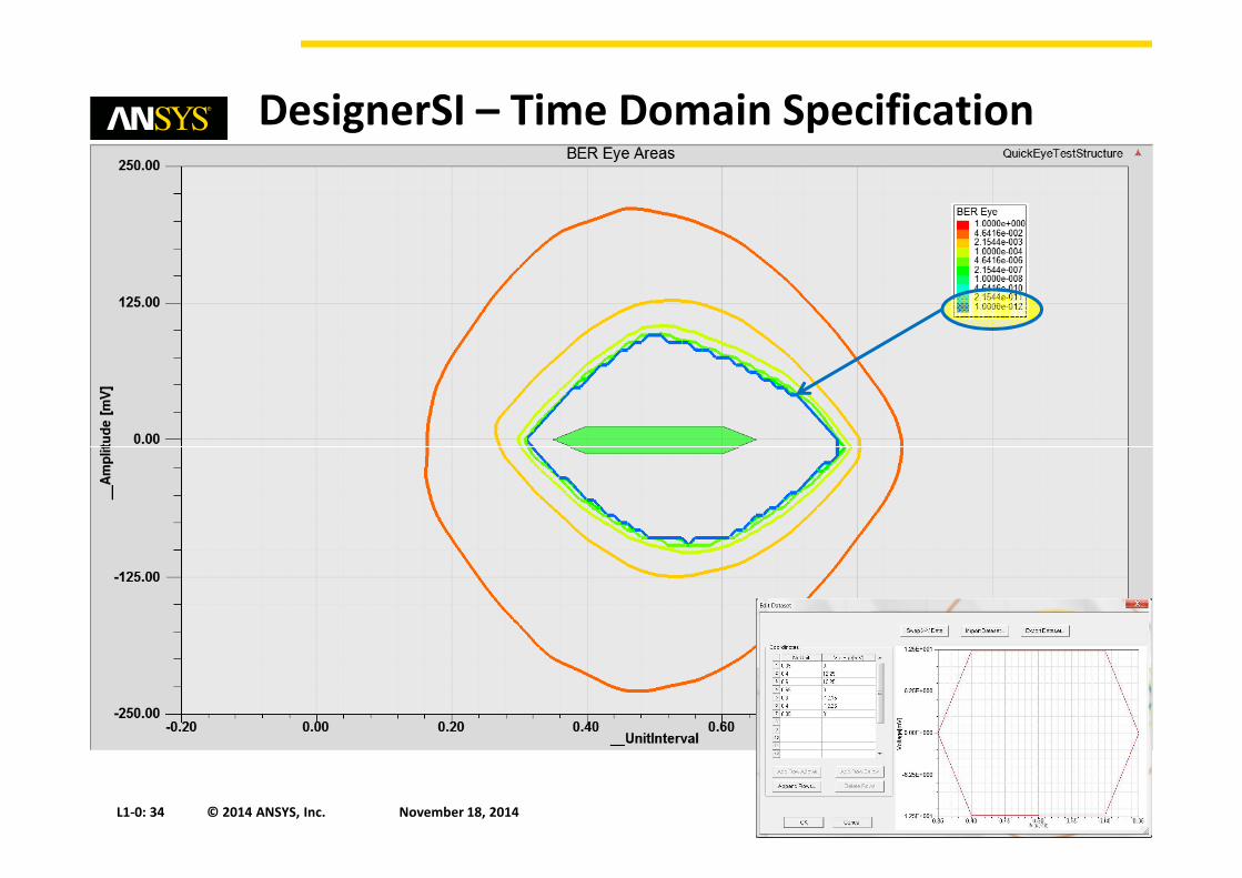
DesignerSI – Time Domain Specification
Rx:
•1 tap DFE
•1st Order CTLE
Tx:
•8 GT/s
•125 ps UI
•25 ps rise & fall times

Release v2014.0November 18, 2014L1-0: 32 © 2014 ANSYS, Inc.
DesignerSI – Time Domain Specification
Symbol Parameter Value Units Comments
VRX-CH-EHEye height 25 (min) mVPP Eye height at
BER=10-12
TRX-CH-EWEye width at
zero crossing
0.3 (min) UI Eye width at
BER=10-12
TRX-DS-OFFSETPeak EH offset
from UI center
+/- 0.1 UI
VRX-DFE_COEFFRange for DFE d1
coefficient
+/- 30 mV Feedback
coefficient

Release v2014.0November 18, 2014L1-0: 33 © 2014 ANSYS, Inc.
DesignerSI – Time Domain Specification
Release v2014.0November 18, 2014L1-0: 34 © 2014 ANSYS, Inc.
DesignerSI – Time Domain Specification

Release v2014.0November 18, 2014L1-0: 35 © 2014 ANSYS, Inc.
DesignerSI – Time Domain Specification

Release v2014.0November 18, 2014L1-0: 36 © 2014 ANSYS, Inc.
User Defined Document (UDD)

Release v2014.0November 18, 2014L1-0: 37 © 2014 ANSYS, Inc.
UDD

Release v2014.0November 18, 2014L1-0: 38 © 2014 ANSYS, Inc.
Summary
• SIwave merged with Alinks to provide a very cohesive flow from
import to simulation.
• SIwave has multiple solver technology options for the users
needs.
– Power integrity and signal integrity
• SIwave can be used solely as a front end tool or linked with
DesignerSI to handle any type of post validation channel
simulation.
• UDO and UDD within Designer enable users to customize and
easily create validation kits and report generation.
• The ANSYS post validation solution backed with accurate
electromagnetic models allows root cause trouble shooting and
optimization.

Release v2014.0November 18, 2014L1-0: 39 © 2014 ANSYS, Inc.
v2014.0 Release
Modern Simulation Solutions for Signal
and Power Integrity for Efficient Design
of PCBs
Peter Krenz, Application Engineer