Embed Size (px)
Citation preview

Wing Flutter Analysis With An Uncoupled Method
M. Sc. Thesis Presentation
Supervisor Prof. Dr. Mehmet A. AKGÜNCo-Supervisor Dr. Erdal OKTAY
Koray KAVUKCUOLU

August 18, 2003 Koray KAVUKCUOLU 2
• Introduction– Flutter
• Flutter Modeling– Simple Systems– Coupled and P-K Methods– Akgün’s Method
• Modal Analysis of AGARD Wing 445.6– Finite Element Model– Results
• Aerodynamic Analysis of AGARD Wing 445.6– USER3D– CFD Model– Solution Procedure– Grid Transformation– Force Calculation– Results
• Numerical Results– Discussion
Presentation Outline

August 18, 2003 Koray KAVUKCUOLU 3
Flutter
Dynamic instability of an elastic body in an airstream caused by the unsteady aerodynamic forces generated from elastic deformations of the structure.
Introduction

August 18, 2003 Koray KAVUKCUOLU 4
αK
α
2b
U
αK
hK
α
U
z
b b
h
x
c.g.ba αbx
yM
Flutter Modeling
1 – DOF System– Rigid Airfoil– Unit Span– Oscillation around the
Leading Edge
2 – DOF System– Rigid Airfoil– Unit Span– Pitching and Plunging Motion
yMKI =+ αα αα iwte0αα =
hh QhmwShm =++ 2αα
ααααα αα QwIIhS =++ 2

August 18, 2003 Koray KAVUKCUOLU 5
Flutter Modeling
[ ] [ ] ( , , , )M q K q f q q q t+ =
P-K Method– Forced Response Analysis– Eigenvalue Solution
[ ] [ ] [ ] 2 210
2h h h hM s K V Qρ η + − =
EOM for the system
– Harmonic displacement
– Transform to Modal Coordinates
Basic EV Flutter Eqn.
)()( ikpib
Vks +=+= γγ * Valid when γ = 0
*

August 18, 2003 Koray KAVUKCUOLU 6
Flutter Modeling
Coupled Methods– Solution of Aeroelastic Equations every time step– Grid Transformation– Coupling Algorithm
– Weakly Coupled (Separate CFD – CSD)– Strongly Coupled (Stability = Least Stable Code)– Fully Coupled (Iterative solution at each time step)
iiiiiii Qqqq =++ 22 ωωζ
– 2 SDOF Equations
– Decoupled by Diagonalization
– Solved at each time step

August 18, 2003 Koray KAVUKCUOLU 7
Flutter Modeling
Present Approach– Forced Response Analysis– Eigenvalue Solution– Aim is to decouple CSD and CFD
[ ] [ ] ( , , , )M q K q f q q q t+ = EOM for the system
[ ] i tq e ωη= Φ– Harmonic displacement
– Transform to Modal Coordinates
Unsteady AerodynamicForce Definition
[ ] ( )Im i tj jf A e ωφ=
[ ] j jr A φ=
• Substitute to EOM and get Eigenvalue flutter problem

August 18, 2003 Koray KAVUKCUOLU 8
Flutter Modeling
[ ] [ ] [ ] [ ] 02 =Φ−− ηω RMK TMM Basic EV Flutter Eqn.
– Similar to P-K method Formulation
– Generalized Aerodynamic Force (GAF) Matrix ( [R] ) is unsymmetric
– [R] = f(M,k) k : reduced frequency
• Transform into a Polynomial Eigenvalue Problem
[ ] [ ] [ ]R IR R i R= +
[ ]P
0
pR p
p
R c T=
=
[ ]P
0
pI p
p
R c Z=
=
– By time integration get real and
imaginary parts of aerodynamic force
– Fit Pth order polynomial to aerodynamic
force

August 18, 2003 Koray KAVUKCUOLU 9
Flutter Modeling
– Polynomial curve fitting in terms of reduced frequency (k)
P
0
0pp
p
k Q η=
=
Polynomial Eigenvalue Flutter Equation
R
I
ηη
η
=
Transform to a real augmented system[Q] is (8x8)
[ ] [ ][ ] [ ]0
00
M
M
KQ
K
=
[ ] [ ][ ] [ ]
2
2 2
00
M
M
MUQ Q
Mb∞
= −
p pQ Q=[ ] [ ][ ] [ ]
T Tp p
p T Tp p
T ZQ
Z Z
− Φ Φ = − Φ − Φ
for p = 1,3,4 … P

August 18, 2003 Koray KAVUKCUOLU 10
Modal Analysis of AGARD Wing 445.6
Finite Element Model
– Shell elements
– Distributed thickness
– Rotated element coordinate system
– In accordance with real wing
-0.6
-0.4
-0.2
0.0
0.2
0.4
0.6
0.0 0.2 0.4 0.6 0.8 1.0
x/c
Thi
ckne
ss (
inch
) Kolonay UpKolonay DownPresent UpPresent DownNACA65004 UpNACA65004 Down

August 18, 2003 Koray KAVUKCUOLU 11
Modal Analysis
– Theoretical Aspects
– Comparison with Experimental Results
[ ] [ ] [ ] 0=++ qKqCqM
– Undamped System
– Harmonic Free Vibrations i tq u e ω= [ ] 0C =
[ ] [ ] 2 0M u K uω− + =
Modal Analysis of AGARD Wing 445.6
– Carried out with ANSYS

August 18, 2003 Koray KAVUKCUOLU 12
Modal Analysis of AGARD Wing 445.6Natural Frequency Comparison
%10.8
%12.2
%16.9
%13.0
-%8.69
-%0.39
-%2.57
% 0.31
-%6.24
% 0.59
-%0.65
%0.92
109.10
56.88
44.57
10.85
Li
89.94
50.50
37.12
9.63
Kolonay
92.358
50.998
37.854
9.688
Present Study
98.50
50.70
38.10
9.60
Experiment
4
3
2
1
Modes
Deflection Comparison
71.52-22.6267.182-22.824
31.38-27.1731.595-27.9233
25.09-45.4845.873-25.3752
27.92-0.08628.093-0.01251
KolonayPresent StudyModes

August 18, 2003 Koray KAVUKCUOLU 13
Modal Analysis of AGARD Wing 445.6
1
MN
MX
X
Y
Z
-.01225
3.7357.483
11.2314.977
18.72522.472
28.093
JUL 26 200317:42:58
NODAL SOLUTION
STEP=1SUB =1FREQ=9.688UZ (AVG)RSYS=0DMX =28.093SMN =-.01225SMX =28.093
1
MN
MX
X
Y
Z
-25.375
-15.876-6.376
3.12412.623
22.12331.623
45.873
JUL 26 200317:43:59
NODAL SOLUTION
STEP=1SUB =2FREQ=37.854UZ (AVG)RSYS=0DMX =45.873SMN =-25.375SMX =45.873
1
MN
MX
X
Y
Z
-27.923
-19.988-12.052
-4.1163.82
11.75519.691
31.595
JUL 26 200317:45:12
NODAL SOLUTION
STEP=1SUB =3FREQ=50.998UZ (AVG)RSYS=0DMX =31.595SMN =-27.923SMX =31.595
Comparison of Mode Shapes
1
MN MX
X
Y
Z
-22.82
-10.821.181
13.18125.181
37.18149.182
67.182
JUL 26 200317:45:42
NODAL SOLUTION
STEP=1SUB =4FREQ=92.358UZ (AVG)RSYS=0DMX =67.182SMN =-22.82SMX =67.182
– The results of the modal analysis are accepted for further use …
1st Mode 2nd Mode
3rd Mode 4th Mode

August 18, 2003 Koray KAVUKCUOLU 14
Aerodynamic Analysis of AGARD Wing 445.6
Aerodynamic Analysis
– USER3D
– Unstructured 3D Euler Solver
– Harmonic oscillation of the wing
– 120 time steps per period for each oscillation frequency
– Grid transformation
– Surface interpolation technique is adopted
– Pressure transformation
– Surface interpolation technique is adopted
– Force Calculation
– Using the pressure distribution on structural model

August 18, 2003 Koray KAVUKCUOLU 15
Aerodynamic Analysis of AGARD Wing 445.6
USER3D
– Parallel finite volume based unstructured 3D Euler solver
– Uses ALE (Arbitrary Lagrangian-Eulerian) formulation
– The flow variables are non-dimensionalised
0
0
0
0
0
0
20 0 0
'
'
'
'
'
'
' '
u u a
v v a
w w a
a a a
T T T
P P a P P P
ρ ρ ρ
ρ γ
= ⋅= ⋅= ⋅= ⋅= ⋅= ⋅
= ⋅ = ⋅
– Pressure is calculated from ideal gas relation
( )
++−−= )(21
1 222 wvuep ργ

August 18, 2003 Koray KAVUKCUOLU 16
Aerodynamic Analysis of AGARD Wing 445.6
USER3D
– Moving Mesh Algorithm
– Spring analogy
( ) ( ) ( )2 2 21
m
j i j i j i
kx x y y z z
=− + − + −
dSnWdVt s
Ω Ω∂
⋅=∂∂
– Geometric Conservation Law
– MPICH library (portable and high performance implementation of MPI)
is used in USER3D for parallelization

August 18, 2003 Koray KAVUKCUOLU 17
Aerodynamic Analysis of AGARD Wing 445.6
CFD Model
– Non-dimensionalised wrt root chord (21.96”)
– Unstructured grid (tetrahedral elements)
– I-DEAS is used to generate mesh
– Half-domain is meshed mirrored full-domain
– The wing profile is NACA 65A004
– 126380 elements & 26027 nodes totally
– 13254 elements & 6667 nodes on the wing
AGARD Wing 445.6

August 18, 2003 Koray KAVUKCUOLU 18
Aerodynamic Analysis of AGARD Wing 445.6
CALCULATEDEFORMED
MESH FOR NEXTTIME STEP
DOUNSTEADY
AERODYNAMICSOLUTION
STOREAERODYNAMIC
SOLUTION DATA
Solution Procedure– Mesh deformation according to mode shapes
– Sinusoidal oscillation for three periods at each frequency
– 10 different frequencies at first 4 mode shapes (40 solution cases)
( )0Q Q sin tω= ×
Mode # Maximum Tip Deflection(inch)
1 0.015
2 0.03
3 0.004
4 0.0015

August 18, 2003 Koray KAVUKCUOLU 19
Aerodynamic Analysis of AGARD Wing 445.6
Grid Transformation– 2D Structural Model 3D CFD Model
– Mode shape transformation
– Surface interpolation by Akima (IMSL)
X (inch)
Y(in
ch)
0 10 20 30 400
5
10
15
20
25
30
35
40 5.6E-03
5.2E-03
4.9E-03
4.5E-03
4.1E-03
3.7E-03
3.4E-03
3.0E-03
2.6E-03
2.2E-03
1.9E-03
1.5E-03
1.1E-03
7.5E-04
3.7E-04
Mode 2 Pe rce nt Error Dis tribution
Frame 002 12 Aug 2003 ERROR DATA
X (inch)
Y(in
ch)
0 10 20 30 400
5
10
15
20
25
30
35
40 4.4E-02
4.1E-02
3.8E-02
3.5E-02
3.2E-02
2.9E-02
2.6E-02
2.4E-02
2.1E-02
1.8E-02
1.5E-02
1.2E-02
8.8E-03
5.9E-03
2.9E-03
Mode 3 Pe rcent Error Dis tribution
Frame 003 12 Aug 2003 ERROR DATA
X (inch)
Y(in
ch)
0 10 20 30 400
5
10
15
20
25
30
35
40 1.7E-02
1.6E-02
1.5E-02
1.4E-02
1.2E-02
1.1E-02
1.0E-02
9.0E-03
7.9E-03
6.8E-03
5.6E-03
4.5E-03
3.4E-03
2.3E-03
1.1E-03
Mode 4 Pe rce nt Error Dis tribution
Frame 004 12 Aug 2003 ERROR DATA
X (inch)
Y(in
ch)
0 10 20 30 400
5
10
15
20
25
30
35
40 2.9E-02
2.7E-02
2.5E-02
2.3E-02
2.1E-02
1.9E-02
1.7E-02
1.5E-02
1.3E-02
1.1E-02
9.5E-03
7.6E-03
5.7E-03
3.8E-03
1.9E-03
Mode 1 Pe rcent Error Dis tribution
Frame 001 12 Aug 2003 ERROR DATAFrame 001 12 Aug 2003 ERROR DATA
Max % error
X (in)
Y(in
)
0 10 20 30 400
5
10
15
20
25
30
35
40
Mo de 1 Comparis onMode 1 12 Aug 2003 MODE SHAP E DATA
X (in)
Y(in
)
0 10 20 30 400
5
10
15
20
25
30
35
40
Mode 2 Comparis onMode 2 12 Aug 2003 MODE SHAPE DATA
X (in)
Y(in
)
0 10 20 30 400
5
10
15
20
25
30
35
40
Mo de 3 Comparis onMode 3 12 Aug 2003 MODE SHAP E DATA
X (in)
Y(in
)
0 10 20 30 400
5
10
15
20
25
30
35
40
Mode 4 Comparis onMo de 4 12 Aug 20 03 MODE SHAPE DATAMo de 4 12 Aug 20 03 MODE SHAPE DATA

August 18, 2003 Koray KAVUKCUOLU 20
Aerodynamic Analysis of AGARD Wing 445.6Force Calculation
– Calculate dimensional pressure distribution
– Use surface interpolation to transfer pressures
CFD Structure mesh at mid points of elements
– Transform pressures at mid-elements to forces at nodes
Pa
Pd
Pb
PcA B
C D
F = Pa(A) + Pb(B) + Pc(C) + Pd(d)
X
X (in)
Y(in
)
0 5 10 15 20 25 30 35 40 450
5
10
15
20
25
30
35
404946433936333026232016131073
Pres s ure Difference Comparis on for the 1s t Mode
DP(Pa)
Frame 001 12 Aug 2 003
X (in)
Y(in
)
0 5 10 15 20 25 30 35 40 450
5
10
15
20
25
30
35
40375350325300275250225200175150125100755025
Pres s ure Difference Comparis on for the 2nd Mode
DP(Pa)
Frame 00 1 12 Aug 200 3
X (in)
Y(in
)
0 5 10 15 20 25 30 35 40 450
5
10
15
20
25
30
35
409875431
-0-1-3-4-5-7-8-9
Pres s ure Diffe rence Comparis on for the 4th Mode
DP(Pa)
Frame 0 01 12 Aug 20 03
X (in)
Y(in
)
0 5 10 15 20 25 30 35 40 450
5
10
15
20
25
30
35
402927252321191715131197420
Pres s ure Difference Comparis on for the 3rd Mode
DP(Pa)
Frame 001 12 Aug 2 003 Frame 001 12 Aug 2 003
August 18, 2003 Koray KAVUKCUOLU 21
Aerodynamic Analysis of AGARD Wing 445.6
CFD Results– Total Lift Coefficient Convergence
– Pressure Distribution
– Total Lift Coefficient Comparison
– Phase DifferenceIte ration
CL
400 450 500 550 600 650 700 750
-0.004
-0.003
-0.002
-0.001
0
0.001
0.002
0.003
0.004
1s t Mode2nd Mode3rd Mode4th Mode
Fra me 0 01 12 Aug 2 00 3 | | | | | | | | | | | | | | | | | | | | | | | | | | | | | | | | | | | | | | |Fra me 0 01 12 Aug 2 00 3 | | | | | | | | | | | | | | | | | | | | | | | | | | | | | | | | | | | | | | |
Tip De flection
CL
-1 -0.8 -0.6 -0.4 -0.2 0 0.2 0.4 0.6 0.8 1
-0.0006
-0.0005
-0.0004
-0.0003
-0.0002
-0.0001
0
0.0001
0.0002
0.0003
0.0004
0.0005
0.0006
1200 s teps /period120 s teps /period
Frame 0 01 12 Au g 2003 Frame 0 01 12 Au g 2003
9.688 Hz
Angle of Attack vs Spanwise Location
-2.0E-02
-1.5E-02
-1.0E-02
-5.0E-03
0.0E+00
5.0E-03
0 10 20 30 40
Y (in)
AOA (
deg)
Mode 1Mode 3Mode 4
Angle of Attack vs Span
-1.8E-01
-1.6E-01
-1.4E-01
-1.2E-01
-1.0E-01
-8.0E-02
-6.0E-02
-4.0E-02
-2.0E-02
0.0E+000 10 20 30 40
Y (in)
AOA (
deg)
Mode 2
Tip Defle ction
CL
-1 -0.8 -0.6 -0.4 -0.2 0 0.2 0.4 0.6 0.8 1
-0.0018
-0.0015
-0.0012
-0.0009
-0.0006
-0.0003
0
0.0003
0.0006
0.0009
0.0012
0.0015 1200 steps /perio d120 steps /period
Frame 001 12 Aug 2003 Frame 001 12 Aug 2003
92.358 Hz

August 18, 2003 Koray KAVUKCUOLU 22
Aerodynamic Analysis of AGARD Wing 445.6
X
Y
0 0.25 0.5 0.75 1 1.25 1.5 1.75 20
0.25
0.5
0.75
1
1.25
1.5 296382923528832284302802727624272212681926416260132561125208248052440324000
PRES S URE DIS TRIBUTION ON THE WING
P (Pa)
F rame 001 12 Aug 2003 F rame 001 12 Aug 2003
– Pressure distribution
X
PR
ES
0.5 0.6 0.7 0.8 0.9 1 1.1 1.2 1.3 1.425000
26000
27000
28000
29000
30000
31000
32000
33000
PRES S URE DIS TRIBUTION ON THE WING AT Y = 0.51 s t Mode at 1 s t Natural Fre que ncy
uppe rlowe r
Fram e 001 18 Aug 2003 Fram e 001 18 Aug 2003
–Total Lift Coefficient Comparison
Ite ration
CL
400 450 500 550 600 650 700 750
-0.0006
-0.0004
-0.0002
0
0.0002
0.0004
0.0006
Force CalculationUS ER3D
Frame 001 12 Aug 2003 Frame 001 12 Aug 2003
NODE
PH
AS
E(D
EG
)
50 100 150 200
50
100
150
200
250
300
350
runM1 12runM1 2runM1 22runM2 12runM2 2runM3 12runM3 2runM3 22runM3 32runM4 2
2nd Mode Phas e Angle VariationFra me 0 01 2 9 Jul 20 0 3 | | | | | | | | | | | | | | | | | | | | | | | | | | | | | | | | | | | | | | |
NODE
PH
ASE
(DE
G)
50 100 150 200
50
100
150
200
250
300
350
run M11 4run M12 4run M14run M21 4run M24run M31 4run M32 4run M33 4run M34run M44
4th Mode Phas e Angle Variation
Fra me 0 01 2 9 Jul 20 0 3 | | | | | | | | | | | | | | | | | | | | | | | | | | | | | | | | | | | | | | |
NODE
PH
AS
E(D
EG
)
50 100 150 200
50
100
150
200
250
300
350
ru nM11 3ru nM12 3ru nM13ru nM21 3ru nM23ru nM31 3ru nM32 3ru nM33ru nM33 3ru nM43
3rd Mode Phas e Angle Variation
Frame 0 01 2 9 Jul 20 0 3 | | | | | | | | | | | | | | | | | | | | | | | | | | | | | | | | | | | | | | |
NODE
PH
AS
E(D
EG
)
50 100 150 200
100
150
200
250 runM11runM111runM121runM21runM211runM31runM311runM321runM331runM41
1s t Mode Phas e Angle Variation
Os cillation Fre que ncy Incres e s
Frame 0 01 2 9 Jul 20 0 3 | | | | | | | | | | | | | | | | | | | | | | | | | | | | | | | | | | | | | | |Frame 0 01 2 9 Jul 20 0 3 | | | | | | | | | | | | | | | | | | | | | | | | | | | | | | | | | | | | | | |
– Phase Difference

August 18, 2003 Koray KAVUKCUOLU 23
Aerodynamic Analysis of AGARD Wing 445.6
CFD Results– Total Lift Coefficient Convergence
– Verified through the Total Lift Coefficient Histograms
– Pressure Distribution
– Order of magnitude comparison to results by simpler methods
– Total Lift Coefficient Comparison
– Around 25 % error is introduced from force calculation
– Phase Difference
– Phase difference exists between each node as expected

August 18, 2003 Koray KAVUKCUOLU 24
Numerical Results
Eigenvalue Solution– Carried out with MATLAB®
– Element Mass and Stiffness Matrices extracted from ANSYS®
– Substructuring analysis
– User Programmable Features of ANSYS®
– Modal Analysis repeated with MATLAB ®
– Mode shapes and natural frequencies are compared
X (in)
Y(in
)
0 10 20 30 400
5
10
15
20
25
30
35
40Z
27.9226 .0524 .1922 .3220 .4518 .5816 .7214 .8512 .9811 .12
9 .257 .385 .523 .651 .78
-0 .09
Mode # 1
Frame 00 1 1 2 Aug 2 00 3
X (in)
Y(in
)
0 10 20 30 400
5
10
15
20
25
30
35
40Z
25.420.615.911.1
6.41.6
-3.1-7.9
-12.6-17.4-22.1-26.9-31.6-36.4-41.1-45.9
Mode # 2
Fra me 0 01 12 Aug 20 03
X (in)
Y(in
)
0 10 20 30 400
5
10
15
20
25
30
35
40Z
27.9223.9519.9916.0212.05
8.084.120.15
-3.82-7.79
-11.75-15.72-19.69-23.66-27.62-31.59
Mode # 3
Frame 0 01 12 Aug 20 03
X (in)
Y(in
)
0 10 20 30 400
5
10
15
20
25
30
35
40Z
22.8216 .8210 .82
4 .82-1 .18-7 .18
-13 .18-19 .18-25 .18-31 .18-37 .18-43 .18-49 .18-55 .18-61 .18-67 .18
Mode # 4
Frame 001 1 2 Aug 2 003 Frame 001 1 2 Aug 2 003
Mode # ANSYS MATLAB
1 9.688 9.688
2 37.854 37.854
3 50.998 50.998
4 92.358 92.358
August 18, 2003 Koray KAVUKCUOLU 25
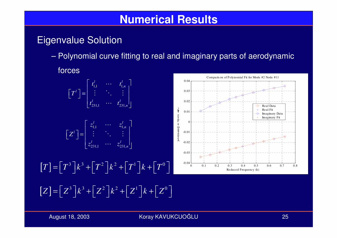
Numerical Results
Eigenvalue Solution
– Polynomial curve fitting to real and imaginary parts of aerodynamic
forces
0 0.1 0.2 0.3 0.4 0.5 0.6 0.7 0.8-0.04
-0.03
-0.02
-0.01
0
0.01
0.02
0.03
0.04
Reduced Frequency (k)
Aerodynamic Force (lb)
Comparis on of Polynomial Fit for Mode #2 Node #11
Real DataReal FitImaginary DataImaginary Fit
1,1 1,
231,1 231,
l ln
l
l ln
t t
T
t t
=
1,1 1,
231,1 231,
l ln
l
l ln
z z
Z
z z
=
[ ] 3 3 2 2 1 0T T k T k T k T = + + +
[ ] 3 3 2 2 1 0Z Z k Z k Z k Z = + + +

August 18, 2003 Koray KAVUKCUOLU 26
Numerical Results
Eigenvalue Solution
– Calculate generalized aerodynamic forces
– Calculate flutter frequency
High
Normal
Deflection
%26.8113.0(rad/s)
82.6897(rad/s)
0.678
%26.9113.0(rad/s)
82.58(rad/s)
0.678
ErrorExperimentPresent StudyMach #
For high deflection case, tip deflection
values are taken from Reference 8

August 18, 2003 Koray KAVUKCUOLU 27
Conclusions & Recommendations– A new approach was applied to AGARD Wing 445.6
– Modal analysis of the wing is performed
– CFD analysis of the wing is performed
– Surface interpolation technique is implemented
– Grid Transformation
– Pressure Transformation
– Polynomial curve fitting to aerodynamic forces is implemented
– Significant decrease in computational time for flutter prediction
– Significant error compared to experiment
– Force calculation technique should be revised
– All experimental cases should be studied
– GAF’s should be verified with literature