Embed Size (px)
Citation preview

Hybrid finite element method in supersonic flutter analysis of circular cylindrical shells
F. Sabri1, A. A. Lakis1 & M. H. Toorani2 1Department of Mechanical Engineering, Ecole Polytechnique of Montreal, Canada 2Nuclear Engineering Department, Babcock & Wilcox Canada, Canada
Abstract
This study is focused on the aeroelastic behaviour of circular cylindrical shells in a supersonic airflow. The development is based on a combination of Sanders’ thin shell theory and the classical finite element method. Potential and piston theory with and without the correction factor for shell curvature is applied to derive the aerodynamic damping and stiffness matrices. The influence of stress stiffness due to the shell internal pressure and axial loading is also taken into account. Aeroelastic equations in hybrid finite formulation are derived and solved numerically. The effect of shell boundary conditions; geometry and flow parameters on the structure response is investigated. In all study cases, the shell loses its stability by coupled-mode flutter where a travelling wave is observed during this dynamic instability. The results are compared with existing experimental data, other analytical and finite element solutions. The present study shows efficient and reliable results that can be applied for the aeroelastic design of shell structures used for aerospace vehicles. Keywords: FSI, hybrid element, flutter, cylindrical shells.
1 Introduction
Shells and plates are among the key structures in aerospace vehicles. For instance, these elements are used numerously in the fuselage and engine nacelles of airplanes and in space shuttles’ skin. As they are exposed to the external air flow and particularly supersonic flow, dynamic instability (flutter) is one of the practical considerations in the design and analysis of skin panels that may occur. Cylindrical shells could also show this kind of aeroelastic instability where
© 2009 WIT PressWIT Transactions on Modelling and Simulation, Vol 49, www.witpress.com, ISSN 1743-355X (on-line) doi:10.2495/BE090211
Mesh Reduction Methods 233
prevention of that behaviour is one of the primary design criterions, which is something that aeronautical engineers are challenged with. After introducing the application of piston theory in the aeroelastic modelling proposed by Ashley and Zartarian [1], many interesting experimental and theoretical studies started to investigate supersonic flutter of a cylindrical shell. Most of these researches are concerned with the development of analytical relations to investigate the effect of the shell and flow parameters on the critical flutter frequency. The aeroelastic models have been developed on the basis of the shell and piston theory to establish the coupled fluid-structure system. Olson and Fung [2] examined the effect of the shell boundary conditions and initial strain state, due to the internal pressure and axial load, on the dynamic behaviour of the given structure. They observed that the pressurized cylindrical shell fluttered at a lower level of freestream static pressure than predicted by theory [3]. Evensen and Olson [4] presented a non-linear analysis for calculating the limit cycle amplitude of a cylindrical shell. Dowell [5] investigated the behaviour of a cylindrical shell in a supersonic flow for different flow and shell parameters; an extensive description of panel flutter modelling has been addressed in his monograph [6]. Amabili and Pellicano [7] developed a model considering the geometric nonlinearities to study the supersonic flutter of the circular cylindrical shell. They also applied the nonlinear piston theory with the shell imperfection to reproduce the experimental data for a pressurized cylindrical shell [8]. The present study is focused on the development of a circumferential hybrid element for a circular cylindrical shell in a supersonic flow. The procedure is similar to the finite element development done for a vertical shell by Lakis and Paidoussis [9] and for a horizontal open shell by Selmane and Lakis [10]. Those developments resulted in a precise and fast convergence with less numerical difficulties. The element is a cylindrical frustum instead of the usual rectangular shell element. Linear Sanders’ shell theory; in which all the strains vanish for rigid body motions; is coupled with the linearized first-order of piston theory (including the curvature correction term) and also the potential theory to carry out the fluid-structure interaction model. The initial stress stiffening in the presence of shell internal pressure and axial compression is also applied into the formulation. Finally the linear mass, damping and stiffness matrix of the aeroelastic system are obtained and solved numerically.
2 Structural model
2.1 Structural mass and stiffness
The equilibrium equations of cylindrical shells according to the Sanders’ shell theory are developed in [10] and [11]. The strain-displacement equations as a function of three infinitesimal displacements in axial (U), radial (W), and circumferential (V) directions are derived and given in [10] and [11]. The system of equilibrium equations described as a function of the displacement components and material properties are defined as:
0),,,( ijJ PVWUL (1)
© 2009 WIT PressWIT Transactions on Modelling and Simulation, Vol 49, www.witpress.com, ISSN 1743-355X (on-line)
234 Mesh Reduction Methods

where JL ( 3,2,1J ) are three partial differential equations and can be found
in [10] and [11]. Matrix [P] is the elasticity matrix for anisotropic shell [11]. A circumferential cylindrical frustum based on the development done by Lakis and Paidoussis [9] is applied to generate the mass and stiffness matrix of the structural model. This element type (see Fig. 1) has two nodal circle with two nodal points i and j .
Figure 1: Geometry of cylindrical frustum element.
There are four degrees of freedom at each node; axial, radial, circumferential displacement, and rotation. This kind of element makes it possible to use thin shell equation easily in order to find the exact solution of displacement functions rather than the approximation with the polynomial functions in the classical finite element method. This element selection results in a hybrid element where a convergence criterion of the finite element method is provided with greater accuracy. Consider the displacement components in the normal manner as:
)sin()(),,(
)cos()(),,(
)cos()(),,(
nxvxrV
nxwxrW
nxuxrU
n
n
n
(2) where n is the circumferential wave number. Lakis and Paidoussis [9] derived the exact analytical relations for the displacement shape functions based on the equations of motion of shell associated with the system of equations (2). The final form of displacement functions is defined as:
j
iN
rxV
rxW
rxU
][
),,(
),,(
),,(
(3) where the nodal displacements vector }{ and displacement shape function
matrix ][N are given in [9]. Now the stress resultant can be defined as:
j
iBP
]][[ (4)
W
U∞ x
WV
θ
wn dwn/dx
xj=l
●
●
i
j
xi=0
U
vn un
© 2009 WIT PressWIT Transactions on Modelling and Simulation, Vol 49, www.witpress.com, ISSN 1743-355X (on-line)
Mesh Reduction Methods 235

Therefore, the mass and stiffness matrix for each element are derived as:
dABPBkdANNhm TT ]][[][][;][][][ (5)
where is the shell density and rdxddA . For the entire shell geometry,
using the standard assembly technique in FEM and applying the appropriate boundary conditions, the global mass and stiffness matrices are found.
2.2 Initial stress stiffness
The influence of membrane forces on the dynamic stability of a cylindrical shell in the presence of the supersonic airflow is investigated. These membrane forces
are due to the pressure differential across the shell mP , and axial compression
xP . It is assumed that the shell is under equilibrium condition and also it has not
reached its buckling state. The initial in-plane shear, static bending and transverse shear are not considered either. The stress resultant due to the internal
pressure mP and the axial compression xP are defined as:
RPNR
PN m
xx
;2
(6)
The potential energy due to this initial strain is equal to:
2
0
222
0
])([2/1 dxRdNNNNU nxxxx
l
i
(7)
where l is the element length, xx is the strain rotation about the x axis, is
the rotation about normal to the x plane, and n is the rotation about normal
to the shell element. The rotation vector is given by:
)
1(
2
1);(
1;
x
VU
R
WV
Rx
Wnxx
(8)
If the displacements are replaced by equation (3), the potential energy in terms of nodal degrees of freedom is generated as:
dxRdr
NN
N
N
rUl
x
xT
i
0
2
0
00
00
00
2/1
(9)
where vector r is defined as:
j
iNC
V
W
U
xR
R
x
r
]][[
2
10
2
1
01
0
00
0
(10) Therefore, the initial stiffness matrix for each element becomes:
dxRdNC
NN
N
N
CNkl TT
x
xTT
I
0
2
0 00 ][][
00
00
00
][][][
(11)
© 2009 WIT PressWIT Transactions on Modelling and Simulation, Vol 49, www.witpress.com, ISSN 1743-355X (on-line)
236 Mesh Reduction Methods

With the help of Maple software, the analytical integration of equation (11) for each element is carried out. The initial stuffiness matrix is superimposed to the global stiffness matrix calculated in equation (5).
3 Aerodynamic modelling
Piston theory is a powerful tool for aerodynamic modelling in aeroelasticity. For a cylinder subjected to an external supersonic airflow parallel to the centreline of the shell, the fluid-structure effect due to external pressure loading can be taken into account by linearized first-order potential theory with (or without) the curvature correction term:
2/122
2
2/12
2
)1(2
1
1
2
)1( MR
W
t
W
UM
M
x
W
M
MpPa
(12)
where p , U , M and are freestream static pressure, freestream velocity, the
Mach number and the adiabatic exponent of air, respectively. At a sufficiently high Mach number ( 2M ) and neglecting the curvature term
2/12 )1(2 MR
W ,
equation (12) is simplified to the so-called linear piston theory as:
t
W
ax
WMpPa
1 (13)
where a is the sound speed. In order to show the compatibility and power of
this development compared with different loading theories, the potential solution proposed by Lakis and Laveau [12] is also applied to account for the pressure field. They have developed an exact expression for the nonlinearized aerodynamic pressure acting on the cylindrical shell that is exposed to external or internal incompressible flow. In this study, the effect of compressibility has been taken into account. This effect is entered through the calculation of Bessel’s functions for finding the velocity potential. Using the Laplace equation for the potential flow accompany with boundary conditions defined by impermeability and Bernoulli’s equation, the linear pressure load on the shell wall is given by:
2
22
2
2
2
2x
WU
tx
WU
t
WZP fa
(14)
where f is fluid density and Z is expressed in terms of Bessel’s functions of
the first and second kind [9]. The radial displacement is defined in terms of the
analytical solution of j (the complex roots of a characteristic equation related to
the equations of motion and oscillation frequency of the shell) and the circular frequency as:
8
1
8
1
)()cos(
jj
j
tR
xi
WneWj
(15) In the following subsection, the pressure field for each aerodynamic loading is expressed in terms of nodal displacements.
© 2009 WIT PressWIT Transactions on Modelling and Simulation, Vol 49, www.witpress.com, ISSN 1743-355X (on-line)
Mesh Reduction Methods 237

3.1 Piston theory
The pressure field expressed by equation (13) can be rewritten as:
8
1
)1
(j
jja x
WM
t
W
apP
(16) Substituting equations (3) and (15) into equation (16), aerodynamic pressure may be defined as:
j
i
fj
j
i
fradiala ARTMpR
iARTa
ppP
][][][)(][][][
0
011
(17)
where the elements of matrix ][ fR are defined in terms of shell radius (R),
longitudinal coordinate (x), and the characteristic equation’s roots ().
3.2 Piston theory with curvature term
The aerodynamic pressure field for the case of applying equation (12) will become as:
j
i
f
j
i
fj
j
i
fradiala
ARTRMM
U
ARTM
U
RiART
M
M
UM
UpP
][][])[)1(2
1(
)1(
][][][)1(
)(][][])[1
2(
1
)1(0
0
1
2/122/12
2
1
2/12
21
2
2
2/12
2
(18)
where is the freestream air density. It is seen that the freestream static
pressure and velocity can be related together through the following equations:
p
aaMU ,. (19)
3.3 Potential theory
Considering the potential theory, the final form for pressure field is given as:
j
i
fj
j
i
fj
j
i
fradiala RTZUR
RTZUR
iRTZpP
]][[)(]][[)(2]][[
0
022
(20)
3.4 Aerodynamic damping and stiffness
The general force vector due to the pressure field is defined as:
dApNF aT
p ][ (21)
Substituting the displacement shape functions (eq. (3)) and the calculated dynamic pressure (eq. (17)) and integrating over the fluid-structure contact
© 2009 WIT PressWIT Transactions on Modelling and Simulation, Vol 49, www.witpress.com, ISSN 1743-355X (on-line)
238 Mesh Reduction Methods

surface, the aerodynamic damping ][ fc , and stiffness ][ fk are determined for
each element as: ]][[][][];][[][][ 1111 AGAkADAc f
Tff
Tf (22)
where
l
fTj
f
l
fT
f dxRRrMpr
iGdxRRrpa
D00
][][][;][][][
(23) The same procedure can be done by substituting the different pressure fields as given in equations (18 and 20) into equation (21) to derive those local damping and stiffness matrices. Finally, global aerodynamic damping ][ fC and
aerodynamic stiffness ][ fK matrices are found through assembling procedure.
4 Aeroelastic model in FEM
The governing equations of motion in the global system of a cylindrical shell exposed to an external supersonic flow are found as:
0]][][][[][][
j
i
fIs
j
i
f
j
i
s KKKCM
(24) where subscripts s and f refer to shell in vacuo and fluid, respectively. It should be noted that in the case of applying potential theory to account for aerodynamic loading, the mass matrix is modified by considering the fluid added mass. In order to find the aeroelastic behaviour of the shell, eigenvalues and eigenvectors of equation (24) are found by means of equation reduction method technique. Dynamic stability of the shell is investigated by studying the eigenvalues in the complex plane. The flutter onset is found when the imaginary part of the eigenvalue changes from positive to negative.
5 Numerical results and discussions
Following shell geometry and flow parameters are used for the given examples.
FTsinaM
inRinLinh
inslbinlbE
t
s
120;/8400;00.3
00.8;4.15;0040.0
/000833.0;35.0;/1016 426
where tT is the freestream stagnation temperature, and s is the shell density.
A set of calculation is carried out to find the appropriate number of elements for shell discretization. It is found that the present model results in a very good accuracy of results using 20 elements. The first set of results along with those of experiment and other theories are presented in Table 1. In all of the cases, the instability is raised in the form of coupled-mode flutter. The proposed method shows a very good agreement with experimental and analytical results.
© 2009 WIT PressWIT Transactions on Modelling and Simulation, Vol 49, www.witpress.com, ISSN 1743-355X (on-line)
Mesh Reduction Methods 239

Table 1: Comparison of shell flutter boundary at 3M and 0 mx pp .
p (psi) criticaln L (in) )/( 2inlbE
Experimental results2 0.380-0.420 20 15.40 0.35 16× 106 Analytical results13 0.420 24 16.00 0.33 13× 106 Analytical results3 0.550 25 15.40 0.35 16× 106 Analytical results7 0.330 27 15.40 0.35 16× 106 FEM results14 0.5621 34 16.00 0.33 13× 106 FEM results15 0.5621 25 16.00 0.33 13× 106 FEM results15 0.5621 26 15.40 0.35 16× 106 Present results 0.522 26 15.40 0.35 16× 106 Present results 0.382 25 16.00 0.33 13× 106
Figure 2: The real and imaginary part of the eigenvalue of system versus freestream static pressure (n=20, Pm=Px=0.0 psi).
The complex frequencies of an unpressurized shell, Pm=0 and n=20, are determined using the potential theory and plotted in fig. 2. It is shown that the flutter occurs at the second axial mode where the imaginary part of eigenvalue, representing the damping of system, passes through zero at high freestream static pressure. The same behaviour was found by Olson and Fung [3]. The effect of the curvature term appearing in the piston theory is examined through the following example. The real and imaginary parts of system eigenvalues are plotted at the first two modes versus freestream pressure as shown in fig. 3. This figure shows that the real parts eventually merge into a single mode. For the further increasing the pressure, the shell loses stability by coupled-mode flutter once the imaginary part of complex frequency crosses the zero value. Prediction of critical freestream static pressure by using equation (12) is closer to the experimental results than evaluating pressure field by equation (13). The complex frequencies for the case that aerodynamic pressure is evaluated using equation (13) are plotted in fig. 4. It is stated that the piston theory including the shell curvature effect results in a better approximation to evaluate the pressure loading on a shell exposed to a supersonic flow. In order to investigate the effect of shell internal pressure, the complex eigenvalues for the critical circumferential wave number n=23, with the shell internal pressure
© 2009 WIT PressWIT Transactions on Modelling and Simulation, Vol 49, www.witpress.com, ISSN 1743-355X (on-line)
240 Mesh Reduction Methods

Figure 3: System eigenvalue versus freestream static pressure when the curvature term is included in the piston theory (n=25, Pm=Px=0.0 psi).
Freestream Static Pressure (Psi) Freestream Static Pressure (Psi)
Figure 4: System eigenvalue versus freestream static pressure without considering the shell curvature effect (n=25, Pm=Px=0.0 psi).
Figure 5: System eigenvalue versus freestream static pressure considering the shell internal pressure (n=23, Pm=0.5psi, Px=0.0 psi).
© 2009 WIT PressWIT Transactions on Modelling and Simulation, Vol 49, www.witpress.com, ISSN 1743-355X (on-line)
Mesh Reduction Methods 241
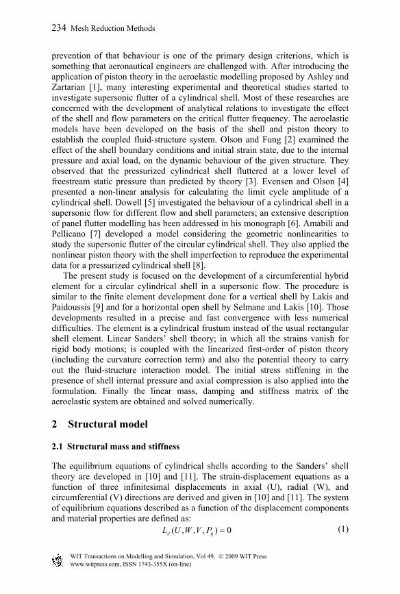
Figure 6: Flutter boundaries for stressed shell, ♦ lbpx 0.0 ; ∆: lbpx 30 .
Figure 7: Flutter boundaries for different RL / ratios, ▲ 4/ RL ; ♦ 2/ RL ;
● 1/ RL .
pm=0.50psi, are shown in fig. 5. In this case, the flutter occurs at higher value of freestream static pressure ( 1.00 psip ) since the shell stiffness increases due to
applied internal pressure. The effect of axial compression on the flutter boundary is also shown in fig. 6. The axial load, Px, decreases the stiffness of the shell, which results in lower critical freestream pressure compared to the unstressed shell. Figure 7 presents the effect of length-to-radius ratio (L/R) on the critical static pressure. For L/R=1, the shell loses its stability at n=18 and P∞=0.171 psi while for L/R=4 onset flutter occurs at n=31 and P∞=1.535 psi.
6 Conclusions
An efficient hybrid finite element method is used to deal with the dynamic stability of circular cylindrical shell subjected to an external supersonic flow. Linear Sanders’ shell theory is coupled with two different potential and piston
0
0.5
1
1.5
2
10 15 20 25 30 35 40
Circumferential Wave Number, n
Cri
tica
l Fre
estr
eam
Sta
tic
Pre
ssu
re (
Psi
)
© 2009 WIT PressWIT Transactions on Modelling and Simulation, Vol 49, www.witpress.com, ISSN 1743-355X (on-line)
242 Mesh Reduction Methods

theory to account for aerodynamic pressure field to derive the aeroelastic equations of motion. It is observed that the piston theory has a better approximation in describing the fluid–structure interaction phenomenon in a supersonic airflow. There is a good agreement for prediction of flutter onset with existed results of experiment, other analytical approaches and FEM analysis. In all cases, only one type of instability is found (known as coupled-mode flutter in form of travelling wave flutter) mostly in the first and second longitudinal modes. Shell internal pressure has stabilizing effect while the axial compression leads to the lower flutter boundary. The developed model is capable to provide reliable results with less computational cost compare to the commercial FEM software where for such analysis, they have some restrictions.
Acknowledgement
The authors acknowledge the financial support of NSERC of Canada, grant No. A8814.
References
[1] Ashley, H. & Zartarian G., Piston Theory-New Aerodynamic Tool for Aeroelastician, Journal of the Aeronautical Sciences, 23(12), pp. 1109-1118, 1956.
[2] Olson, M.D. & Fung Y. C., Supersonic Flutter of Circular Cylindrical Shells Subjected to Internal Pressure and Axial Compression, AIAA Journal, 4(5), pp. 858-864, 1966.
[3] Olson, M. D. and Fung, Y. C., Comparing Theory and Experiment for Supersonic Flutter of Circular Cylindrical Shells, AIAA Journal, 5(10), pp. 1849-1856, 1967.
[4] Evensen, D.A. & Olson M. D., Nonlinear Flutter of a Circular Cylindrical Shell in Supersonic Flow, NASA TN D-4265, 1967.
[5] Dowell, E. H., Flutter of Infinitely Long Plates and Shells. Part II, AIAA Journal, 4(9), pp. 1510-1518, 1966.
[6] Dowell, E.H., Aeroelasticity of Plates and Shells, Noordhoff International Publishing, Leyden, 1975.
[7] Amabili, M. & F. Pellicano, Nonlinear Supersonic Flutter of Circular Cylindrical Shells, AIAA Journal, 39(4), pp. 564-573, 2001.
[8] Amabili, M. & F. Pellicano, Multimode Approach to Nonlinear Supersonic Flutter of Imperfect Circular Cylindrical Shells, Journal of Applied Mechanics, Transactions ASME, 69(2), pp. 117-129, 2002.
[9] Lakis, A. A. & Paidoussis, M. P., Dynamic Analysis of Axially Non-Uniform Thin Cylindrical Shells, Journal of Mechanical Engineering Science, 14(1), pp. 49-71, 1972.
[10] Selmane, A. & Lakis, A. A., Non-Linear Dynamic Analysis of Orthotropic Open Cylindrical Shells Subjected to a Flowing Fluid, Journal of Sound and Vibration, 202 (1), pp. 67-93, 1997.
© 2009 WIT PressWIT Transactions on Modelling and Simulation, Vol 49, www.witpress.com, ISSN 1743-355X (on-line)
Mesh Reduction Methods 243
[11] Toorani, M. H. & Lakis, A. A., General Equations of Anisotropic Plates and Shells Including Transverse Shear Deformations, Rotary Inertia and Initial Curvature Effects, Journal of Sound and Vibration, 237(4), pp. 561-615, 2000.
[12] Lakis, A. A. & Laveau, A., Non-Linear Dynamic Analysis of Anisotropic Cylindrical Shells Containing a Flowing Fluid, International Journal of Solids and Structures, 28(9), pp. 1079-1094, 1991.
[13] Carter, L. L., & Stearman, R. O., Some aspects of cylindrical shell panel flutter, AIAA Journal, 6(1), pp. 37-43, 1968.
[14] Bismark-Nasr, M. N., Finite element method applied to the supersonic flutter of circular cylindrical shells, International Journal for Numerical Methods in Engineering, 10(2), pp. 423-435, 1976.
[15] Ganapathi, M., Varadan, T. K., Jijen, J., Field-consistent element applied to flutter analysis of circular cylindrical shells, Journal of Sound and Vibration, 171(4), pp. 509-527, 1994.
© 2009 WIT PressWIT Transactions on Modelling and Simulation, Vol 49, www.witpress.com, ISSN 1743-355X (on-line)
244 Mesh Reduction Methods


![Supersonic Flutter of a Spherical Shell Partially …Ganapathi [12]et al. modeled an orthotropic and laminated aniso-tropic cylindrical shell in supersonic flow using FEM and analyzed](https://img.dokumen.tips/doc/110x75/5e3e4d56bb497d7d23496b67/supersonic-flutter-of-a-spherical-shell-partially-ganapathi-12et-al-modeled-an.jpg)


![Supersonic Flutter of a Spherical Shell Partially Filled ...file.scirp.org/pdf/AJCM_2014051617014328.pdf · comprehensive experimental test was done by Fung and Olson [4]. ... Aeroelasticity](https://img.dokumen.tips/doc/110x75/5b0474227f8b9a0a548d9ac4/supersonic-flutter-of-a-spherical-shell-partially-filled-filescirporgpdfajcm.jpg)