Embed Size (px)
Citation preview
Rev. 2.0, 2-15-2012
Fancy Foam Models, LLC635 Laramie Cir. Maize, Ks. 67101www.fancyfoam.com
SST (Sloper Steve Tribute) – Assembly Instructions.
The SST is a slope glider flying wing designed for Ultrabatics. A thin symmetrical airfoil, light weight and extra large elevons allow extreme aerobatic flight in even the lightest lift.
These instructions will cover the build of both the 30” version and 48” version. Notes will be provided throughout these instructions about the few differences in the build.
Recommended Electronics:It is up to the builder to decide how light to build this kit. The instructions are for the recommended build. It is your option to deviate from this to make it lighter/less durable or heavier/more durable.
Servos: (2) 9gram. - 48” SST (2) 2.9gram – 30” SST
Receiver: 4-6 channelBattery: 1 or 2 cell 600mah lipo – 48” SST
1 cell 360mah lipo – 30” SSTTransmitter: To achieve 90 deg up throw a computer radio is required. Elevon mixing is also required.
Note: it is preferred that the receiver be able to take direct 1 or 2 cell battery voltage. If not then you will need a voltage regulator/booster as required.
Build options:The SST can be built to weight between 7 and 12oz depending on how light you want it to be verses durabiltity.An ultralight build mainly involves using less covering. The Tiplets are only covered around the perimeter. The wing leading edge is covered and part of the elevons are covered. You can use as small of a battery as you want and still get the CG correct.A durable build would involve covering the whole wing and tiplets. You can run a bigger battery with this build up to about a 2s-700 mah.Flying has shown that there is not very much advantage to getting below 9oz weight so full covering can be done without much concern.In either case we recommend using a minimum of a 9gram servo due to the large size of the elevons.
Painting:The covering is clear once it has been applied so painting the bare foam works well. EPP is solvent resistant so normal spray can paint like Krylon will work great.
Glue:The recommended construction glue is Beacon Foam-Tac. It is a clear contact adhesive that remains flexible when
dry which works excellent with the flexible EPP foam. It can be used for general construction as well as for hinging the control surfaces.Wing construction:Glue the two wing halves together. When the glue is dry, use straight pins to hold the spar as shown. The middle of the spar should be about 7” from the leading edge . The ends of the spar should be about 2” from the leading edge.
Cut a slit in the foam near the 0.5 x 3mm carbon spar. The cut can be made ¼” off of the carbon to make the cutting easier. Turn the wing over and repeat on the bottom trying to make sure the spars are lined up. Apply glue to the cut and press the spar through the glue and into the cut so it is flush or just below the surface of the wing. Straighten the wing so it is flat and let the glue cure. Once the top side is done repeat on the bottom side.
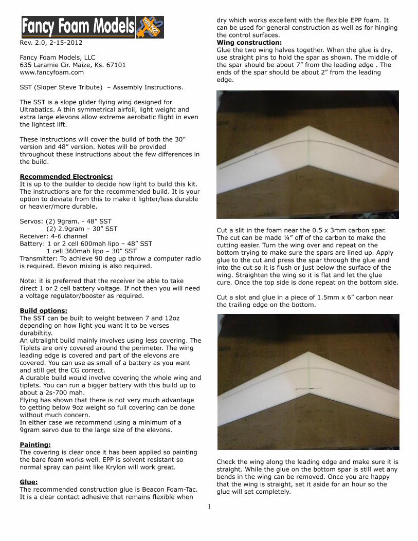
Cut a slot and glue in a piece of 1.5mm x 6” carbon near the trailing edge on the bottom.
Check the wing along the leading edge and make sure it is straight. While the glue on the bottom spar is still wet any bends in the wing can be removed. Once you are happy that the wing is straight, set it aside for an hour so the glue will set completely.
1

Gear Placement:Cut 4 pieces of covering for the top/bottom and left/right sides. The pieces should be 1” larger than the wing on all sides but only 1/4” over on the trailing edge. If you do not get complete coverage with the supplied film, make it short on at the nose as this will be covered last.
Tape the elevons to the trailing edge. Tape all the covering to the top of the wing roughly in place. Tape the servos roughly in place with the carbon push rods as well as the receiver and the battery. Move the servos, receiver and battery until you have the CG at 9-1/2” from the nose. With the recommended components you should not have to use any extra weight. Mark the position of the servos, receiver and battery.
Cut out pockets for the servos, receiver and battery. It may be easiest to cut all the way through the foam and remove the foam block. Cut out the center of the block to make room for the component and then glue the top and bottom foam pieces back in place with the component sandwiched in place.
For the battery connection, I have the battery plug run out the top of the wing and then leave a hole for it to plug into the receiver.
Electronics installation:
Make a new model on your radio and set it up for elevon mixing. Change the end point and dual rate values to 150%. Plug the servos into the receiver and power it up. Center the control horn on the servo and then use sub trim to rotate the servo arm about 20 deg aft. To get full 90 deg up on a JR/Spektrum radio you will need to create a mix that mixes elevator to elevator to increase the elevator throw. Play with the sub trim and travel adjust to get the most throw that you can.
Cut a 1/4” deep slit from the servo pocket to the receiver location. Glue the servos into their pockets. Push the servo wire down into the slit in the foam and plug them into the receiver. Mount the receiver and battery in place and glue their foam covers in place.
Covering:If you are going for a light build, cut covering a minimum of 4” wide and apply to the leading edge of the wing. Cover from 1” in front of the hinge to 1/8” behind the trailing edge of the elevons top and bottom.
For the medium weight build, cover the entire wing top and bottom. Overlap around the leading edge by 1” and extend behind the trailing edge 1/8”.
There should be a slight gap between the wing and elevon at the hinge, about 1/16” so that the top and bottom covering will actually touch each other.
When you are done you can use a straight edge to trim the covering at the trailing edge to 1/8” behind the foam to give a nice thin edge.
The foam at the center from the left and right sides will over lap each other about 1” on each side. For the covering at the tips, make sure the top and bottom pieces over lap each other so they will not pull apart.
Cut the covering from above the servo horns and the receiver where the battery plugs in.
2
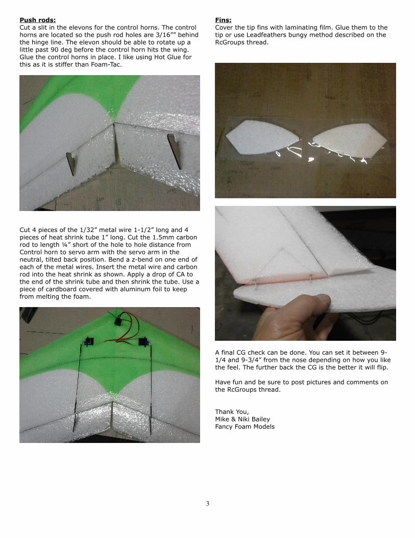
Push rods:Cut a slit in the elevons for the control horns. The control horns are located so the push rod holes are 3/16”” behind the hinge line. The elevon should be able to rotate up a little past 90 deg before the control horn hits the wing. Glue the control horns in place. I like using Hot Glue for this as it is stiffer than Foam-Tac.
Cut 4 pieces of the 1/32” metal wire 1-1/2” long and 4 pieces of heat shrink tube 1” long. Cut the 1.5mm carbon rod to length ¼” short of the hole to hole distance from Control horn to servo arm with the servo arm in the neutral, tilted back position. Bend a z-bend on one end of each of the metal wires. Insert the metal wire and carbon rod into the heat shrink as shown. Apply a drop of CA to the end of the shrink tube and then shrink the tube. Use a piece of cardboard covered with aluminum foil to keep from melting the foam.
Fins:Cover the tip fins with laminating film. Glue them to the tip or use Leadfeathers bungy method described on the RcGroups thread.
A final CG check can be done. You can set it between 9-1/4 and 9-3/4” from the nose depending on how you like the feel. The further back the CG is the better it will flip.
Have fun and be sure to post pictures and comments on the RcGroups thread.
Thank You,Mike & Niki BaileyFancy Foam Models
3