Embed Size (px)
Citation preview
American Institute of Aeronautics and Astronautics
1
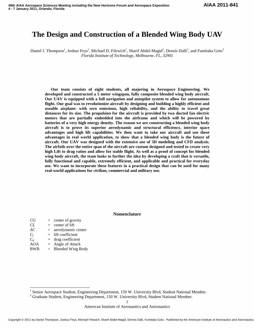
The Design and Construction of a Blended Wing Body UAV
Daniel J. Thompson1, Joshuo Feys1, Michael D. Filewich1, Sharif Abdel-Magid1, Dennis Dalli1, and Fumitaka Goto2 Florida Institute of Technology, Melbourne, FL, 32901
Our team consists of eight students, all majoring in Aerospace Engineering. We developed and constructed a 5 meter wingspan, fully composite blended wing body aircraft. Our UAV is equipped with a full navigation and autopilot system to allow for autonomous flight. Our goal was to revolutionize aircraft by designing and building a highly efficient and useable airplane: with zero emissions, high reliability, and the ability to travel great distances for its size. The propulsion for the aircraft is provided by two ducted fan electric motors that are partially embedded into the airframe and which will be powered by batteries of a very high energy density. The reason we are constructing a blended wing body aircraft is to prove its superior aerodynamic and structural efficiency, interior space advantages and high lift capabilities. We then want to take our aircraft and use these advantages in real world application, to show that a blended wing body is the future of aircraft. Our UAV was designed with the extensive use of 3D modeling and CFD analysis. The airfoils over the entire span of the aircraft are custom designed and tested to create very high Lift to drag ratios and allow for stable flight. As well as a proof of concept for blended wing body aircraft, the team looks to further the idea by developing a craft that is versatile, fully functional and capable, extremely efficient, and applicable and practical for everyday use. We want to incorporate these features in a practical design that can be used for many real-world applications for civilian, commercial and military use.
Nomenclature CG = center of gravity CL = center of lift AC = aerodynamic center Cl = lift coefficient Cd = drag coefficient AOA = Angle of Attack BWB = Blended Wing Body
1 Senior Aerospace Student, Engineering Department, 150 W. University Blvd, Student National Member. 2 Graduate Student, Engineering Department, 150 W. University Blvd, Student National Member.
49th AIAA Aerospace Sciences Meeting including the New Horizons Forum and Aerospace Exposition4 - 7 January 2011, Orlando, Florida
AIAA 2011-841
Copyright © 2011 by Daniel Thompson, Joshuo Feys, Michael Filewich, Sharif Abdel-Magid, Dennis Dalli, Fumitaka Goto. Published by the American Institute of Aeronautics and Astronautics, Inc., with permission.

American Institute of Aeronautics and Astronautics
2
Figure 1. BWB Interior 5
I. Introduction Presently, the airplane as we know it does a very good job at transporting people and cargo from point A to point B; however, there is room for improvement. Due to a tough economic environment, efficiency is taking an increasingly prominent role in aircraft design. In the past 30 years, major technological advancements have been achieved in propulsion systems, structures, and electronics; however, there hasn't been a major technological breakthrough in aerodynamic geometry for a few decades. Airplane aerodynamics are constantly tweaked, but the general layout of an airplane has hardly deviated from blueprints that were made with a slide rule. As a result we have made it our objective to design, construct, and fly a Blended Wing Body UAV. This design is fundamentally superior to conventional tube and wing airframes, due to the elimination of a non-lifting fuselage and unnecessary surfaces on the aircraft, and better integration of the propulsion system into the airframe. Our goal is to create not only a functional flying prototype, but also an airframe that is fully mission-capable as a UAV. This airframe will serve as a technology demonstration to prove why Blended Wing Bodies are the aircraft of the future.
II. Background and Overview Based on research and development, it has been found that the potential of the hybrid wing body aircraft is not
only innovative, but also revolutionary. This aircraft is known to have many advantages over the conventional tubular fuselage plane (e.g. Boeing 777). The two main advantages that blended wing body aircrafts possess are better aerodynamic efficiencies and more interior space capability. By being more aerodynamically efficient, a
BWB needs less power and therefore less fuel is burned to propel it forward compared to a conventional tubular fuselage aircrafts. A BWB aircraft has better aerodynamic efficiency because the wings are blended with the fuselage which eliminates the additional drag that is created on a conventional aircraft where the wing’s surface mates to the body. Also, a BWB does not have the long tail structure that consists of a horizontal stabilizer and rudder that typical airplanes have. That particular tail section creates an abundance of drag, which gives the BWB an exceptional edge over conventional aircrafts. Not only is there less profile drag on a BWB, but BWBs are considered to be an innovative technological breakthrough by generating more lift than a conventional plane for the same wingspan. The BWB fuselage can create up to 60 percent of the lift through the center section, unlike conventional plane fuselages that do nothing aerodynamically. This is due to the fact that the whole BWB plane is comprised of airfoils creating more lift and allowing the plane to carry more payload/cargo than a conventional aircraft of the same wingspan.
The other main advantage that the BWB possess is the varying capabilities of its interior space. Figure 1 illustrates the interior space advantage of a BWB and its abundance of useable volume. There is a significant difference in the amount of usable space as compared to a tubular fuselage airplane. The BWB has more room for passengers because it is not constricted to the typical cylindrical shape. Passengers will be able to actually sit in the thicker portions of the wing section because of the large interior volume before the transition to the actual wing section gets too thin. Another large advantage of a BWB is that the structure has a more even distribution for weight. This allows for a lighter and smaller structure to handle all the loads on the aircraft, which in turn, yields more cargo weight carrying ability and interior space. Figure 2 shows a comparison between the weight and lift distributions of conventional and BWB aircrafts. The BWB weight and load distribution is much more even allowing for a large advantage over standard aircrafts.
Figure 2. Lift vs. Weight Distribution of a Conventional Aircraft and a BWB.

American Institute of Aeronautics and Astronautics
3
The BWB incorporates numerous groundbreaking technologies; however all the advantages of a blended wing aircraft come at the cost of a few disadvantages. The first of which is that it does not incorporate a tail section which leads to potential flight stability issues especially in the pitch regime. No tail section means it will be difficult to balance out the moments due to the pressure distribution over the lift generating airfoils. This is because of the inherent small moment arm on a BWB for the rear most control surfaces. It is possible to correct this complication through the use of custom airfoils, proper center of gravity placement, and the use of many control surfaces.
There may also be complications to pressurize the cabin. The issue lies within the shape, because typical aircrafts have a cylindrical shape which requires less strength and is easier to pressurize as appose to the interior shape of a BWB. This is very minuet, but is being taken into consideration. Furthermore, the commercial use of a BWB will need to take some getting used to on behalf of the payload/passengers. BWB aircrafts will not incorporate personal windows based upon its shape. The norm for passengers is having the ability to see outside the plane, but by not having this ability could lead to passenger discomfort. There could also be a passenger motion sickness issue for people sitting further out from the center of the plane, because when the BWB rolls, these people will feel much more physical motion. Overall, despite these few disadvantages, BWB aircrafts remain supreme to the conventional aircraft, solely due to the fact that given the same wingspan the BWB is conclusively more efficient and economical.
Currently, the main development and research of blended wing aircraft is being conducted by Boeing Phantom Works along with NASA. Boeing has designed and successfully test-flown their X-48B hybrid wing aircraft. The X-48B was a proof of aerodynamic concept that demonstrated phenomenal aerodynamic supremacy, implementing stability and control similar to that of standard aircraft. Numerous propulsion types/system designs for BWB aircrafts are being researched. Certain companies are designing ways to include the use of embedded engines. Currently in industry, blended wing aircrafts are not commercially on the market. Today airplanes are still designed with tubular fuselages and wings. The delta wing, such as the B2, is the only type of design being used today that is somewhat similar to the BWB concept. Boeing does plan to create a full size commercial blended wing aircraft, but it may take a few decades. They are confident in the idea of BWB based on the proof of concept X-48B aircraft. We are confident the future of commercial aircraft will be the blended wing body. The Boeing BWB was just a proof of concept; we want to use our knowledge and create a UAV that is not only a proof of superiority among aircraft but also create a fully functional and useable UAV.
III. Goals The following describes our goals that were set for the completion of our project. For more detail refer to the
System Requirements Review. The deliverables for this project will be an aircraft that meets the criteria of our system specifications.
A. Timeline

American Institute of Aeronautics and Astronautics
4
B. Project Reviews The project is being organized into your Standard framework of a professional design process: SRR (Systems Requirement Review) • Can be changed at any time PDR (Preliminary Design Review) • Trade Studies TIM (Technical Interchange Meeting) • Where we hold a meeting, and answer action items CDR (Cumulative Design Review) • Is a PDR re-design, answering all of the action items PRR (Production Readiness Review) • Organizing all the info in PowerPoint Presentations (PowerPoint Engineering) To show the plane’s readiness for flight, we will have a “Qual” Program, meaning a program that puts our plane
through testing meeting certain standards (ex. - MIL-STD 1540). Then, we start producing the airplane, using an Acceptance Test Procedure (ATP).
Systems Requirements Review Goals Performance Parameters Blended Wing Body design Zero emissions from takeoff to touchdown Practical design (cargo, mission capable) Fully electric battery power Real-world usability Propulsion: Two electric motors Environmentally friendly Fly full waypoint missions High lift capability Carry 100% of empty weight in cargo High efficiency Cruise Speed: 70 knots (~ 36m/s) Wingspan: 5 meters Takeoff weight (empty): ~ 25 kg Takeoff weight (max): ~ 50 kg Max range: ~ 60 km Max flight time: ~ 35 minutes Test model size: 1.5m wingspan Emergency systems:
Manual override of autopilot Emergency parachute Auto return home feature
Applications: Surveillance and Reconnaissance
Medical or other supplies transport use Rush cargo Humanitarian Relief
Military use (weaponry, battlefield guidance)

American Institute of Aeronautics and Astronautics
5
Figure 4. SolidWorks Models of Design Prototypes.
IV. Design
A. Introduction Every airplane goes through many design changes before it is finally produced. The steps between the first ideas
for an airplane and the time when it is put into production make up the design process. Along the way, engineers think about four main areas of aeronautical design: Aerodynamics, Propulsion, Structures and Materials.
Usually an airplane is designed to fulfill a given mission. Once this goal is decided, the craft is given a set of
specifications that need to be met (cargo, volume, lift capacity, speed, range, etc.). From this point we started to branch out and conceptualize the different aspects of the airplane. The order of our design process can be seen in the following flowchart (Fig. 3).
Figure 3. Design Flowchart.
Using solids modeling software (SolidWorks) we create a 3D model of the plane and every component inside. Other computer software was used to test aerodynamics of the model and to test the structure we built for this plane. The computer models helped us facilitate the building process, allowing us to create an accurate mold for the layup of the body, full scale engineering drawings, etc. We built a small model which was used in wind tunnel testing, in order to backup our CFD data, and another slightly larger gliding model to test real world flight characteristics. We also had
to calculate the equivalent Reynolds numbers for the models in order to scale to the full aircraft. After these parts of the design process are completed, we are ready to start building our full scale plane. We want to finalize the design before we start building.
B. Aerodynamics The aerodynamics of a blended wing aircraft are much
different and more difficult than those of a conventional aircraft. Every movement that any aircraft does, whether it is pitch, roll or yaw, acts about the center of gravity of the airplane. Since there is no tail section on a BWB, this poses many problems with directional control and pitch control of the aircraft. This is because the moment arm length from the CG to the elevators and rudders is very small which inherently does not allow for very much control authority. The absence of the tail section also creates stability problems because there is no large horizontal and vertical stabilizer located far back, which would help the airplane much more to fly straight and level. The absence of a large vertical stabilizer/tail rudder makes yaw control difficult, but the issue is addressed on our airplane by using thrust variation with the engines in combination with small rudders on the winglets.

American Institute of Aeronautics and Astronautics
6
The biggest stability issue with a tailless aircraft is pitch stability. The first thing that MUST be done for the aircraft to be statically and dynamically stable is to make sure that the center of gravity of the aircraft is located in front of the center of pressure of the entire aircraft. In addition, the airfoils on a BWB must be completely different than a conventional aircraft in order to allow for pitch stability. We must use low cambered airfoils so that the aerodynamic moment is kept to a minimum. Normally airfoils are highly cambered so they can generate a lot of lift, but this comes at the expense of high negative moment which would have to be counterbalanced. So our goal when designing the airfoils for this airplane was to create high lift to drag ratios for airfoils that have a very low moment. Every airfoil used in our plane was custom designed through research, and basis off similar airfoil design and data. We also performed hundreds of trial and error 2D and 3D CFD tests to come up with the most appropriate airfoil
solutions. In order for the airfoils to make useful lift they still had to have some amount of camber, so we employed aspects of the airfoil design that would still keep the overall moment low. The first was making the position of max camber far forward on the airfoil chord. One negative of this is that it moves the center of pressure more forward which hurts aircraft stability; so a design tradeoff must be made. The second design feature was using reflex at the trailing edge of the airfoil which helped negate the inherent negative moment that airfoils have. Using reflexed airfoils greatly helped the stability of the aircraft, as there is no tail section on our plane that would normally counter the heavy negative moment of a cambered airfoil.
Figure 5. Aluminum airfoil profiles. Another method we used to counter the lifting airfoils’ negative aerodynamic moments and solve aircraft
instability was to employ aerodynamic twist and physical twist in our wings. Aerodynamic twist is where the airfoil geometry changes as you progress toward the wingtip, usually in order to change the zero lift angle of attack for that section of the wing; and physical twist is an actual measured twist (in radians or degrees) of the wing along its horizontal span axis. The aerodynamic geometry of our airplane is comprised of five different airfoils and the transitions between them. One feature our aircraft incorporates to aid in pitch stability is a transition to a custom “upside-down” airfoil at the wing tip which makes negative lift when the airplane is flying steady level (Fig. 6). This creates a downward force behind the CG which adds positive moment force to the entire aircraft. We also used a physical twist in the wing so that the very tips of the wings are at a negative 4o AOA, which also aids in adding a positive moment around the CG for steady level flight. The “inverted” airfoil profile at the wing tips provided a stability solution with much less drag on the plane than if we were to use a standard airfoil coupled with much more negative angle wing twist. The airfoils at the center body section of the aircraft had to be designed as thicker airfoils so that the airplane could have a significant interior volume in order to accommodate the cargo it will need to carry. The thicker center body also helps improve structural strength. The center airfoil section is at 18 percent chord thickness, which we found as basically the upper limit of airfoil thickness before the drag starts to get significantly too high for the airfoil. The side airfoil profile as you progress from the center to the wing tip can be seen in Fig. 6. We also incorporated a 2 degree AOA in the wing root airfoil, so that this area would be the first to stall. Forcing the armpits of the wings to stall first allows for very favorable stall characteristics and helps prevent entering a spin.
Another aerodynamic design aspect we had to incorporate was the wing sweep of 33 degrees. Sweeping the
wings back helps with roll stability and it moves the center of pressure farther backward which allows for more lenient cargo placement areas. The wing sweep also moves the control surfaces further back and allows the plane to fly better at faster speeds. The plane also has an overall positive dihedral which also aids in roll stability. Winglets are incorporated at the wing tips to eliminate wing tip vortices that cause induced drag on the airplane. Our winglets will be slightly oversize so that they can be also used as rudder surfaces for the yaw control. On the tips of the winglets we incorporated “c-wings” which are inward facing small surfaces which can be hand adjusted to dial in the pitch properties of the aircraft by creating more or less overall moment around the CG. Designing a BWB to maximize the lift to drag ratio, while at the same time keeping the aircraft stable, is a difficult design process that
Figure 6. SolidWorks side profile view of UAV.

American Institute of Aeronautics and Astronautics
7
runs in a never ending circle. Improving one aerodynamic design aspect will always hurt more than one other; so important tradeoffs must be made. Our entire plane overall has a high lift to drag ratio for its size, and even though the Cl’s for each airfoil are not as high as conventional airplanes, the shape and form of our aircraft allow for its high lift, low total drag and high efficiency.
C. Computational Fluid Dynamics (CFD) Analysis Preliminary design analysis of our aircraft was done using ANSYS 12.0, Gambit, and Fluent. We decided to
initially base our aircraft on the NACA 2412, MH45 and TL54 reflex airfoils. CFD was used to determine the coefficients of lift, drag and moment for each airfoil at various angles of attack. We then used the basis of these airfoils to create all new custom airfoils in which we designed with extensive research and by performing hundreds of CFD tests. We then compared airfoil data within our own designs for their respective airfoil locations on our airplane. We compared the angle of attack of each newly designed airfoil versus performance of Cl and Cd and moment coefficient assuming constant properties of: free stream velocity, air density, and air viscosity, The shear stress transport model was used at the boundary layer. The air was also assumed to be steady state, adiabatic, and turbulent. We performed 2D airfoil simulations and many 3D CFD simulations of the entire aircraft profile. We also performed hand calculations based off the individual airfoil data to calculate the aerodynamic forces of the entire aircraft and compared it to the 3D simulations. The aircraft has now gone through 5 major design iterations and each new shape was tested in Fluent to show any performance gains or losses from a new design prototype.
Figure 7. CFD test of final geometry. Figure 8. Deep Stall.
Figure 9. Stall Approximation (Dynamic Pressure Mapping)
D. Materials and Structures Structures and Materials is a critical part of the design process and deals with how strong the airplane is and
what materials will be used to build it. It is really important for an airplane to be as lightweight as possible, especially in our case. The less the plane weighs the less work the engines have to perform, and the plane can fly further. We accomplished a very light aircraft through engineering the airframe to include various types of advanced composites. Composites are a makeup of two or more constituent materials bonded together but which still remain distinguishable in final form. Most composites use two completely different materials, one of which acts as the binder or matrix and the other which is the reinforcement.
Most composites have a better strength to weight ratio than most metals. Our plane’s airframe is made up of 100 percent composite materials, most of which is carbon-epoxy and glass-epoxy.
0o 5o 1 5o 20o 25o 30o
0o 5o 15o 20o 25o 30o
American Institute of Aeronautics and Astronautics
8
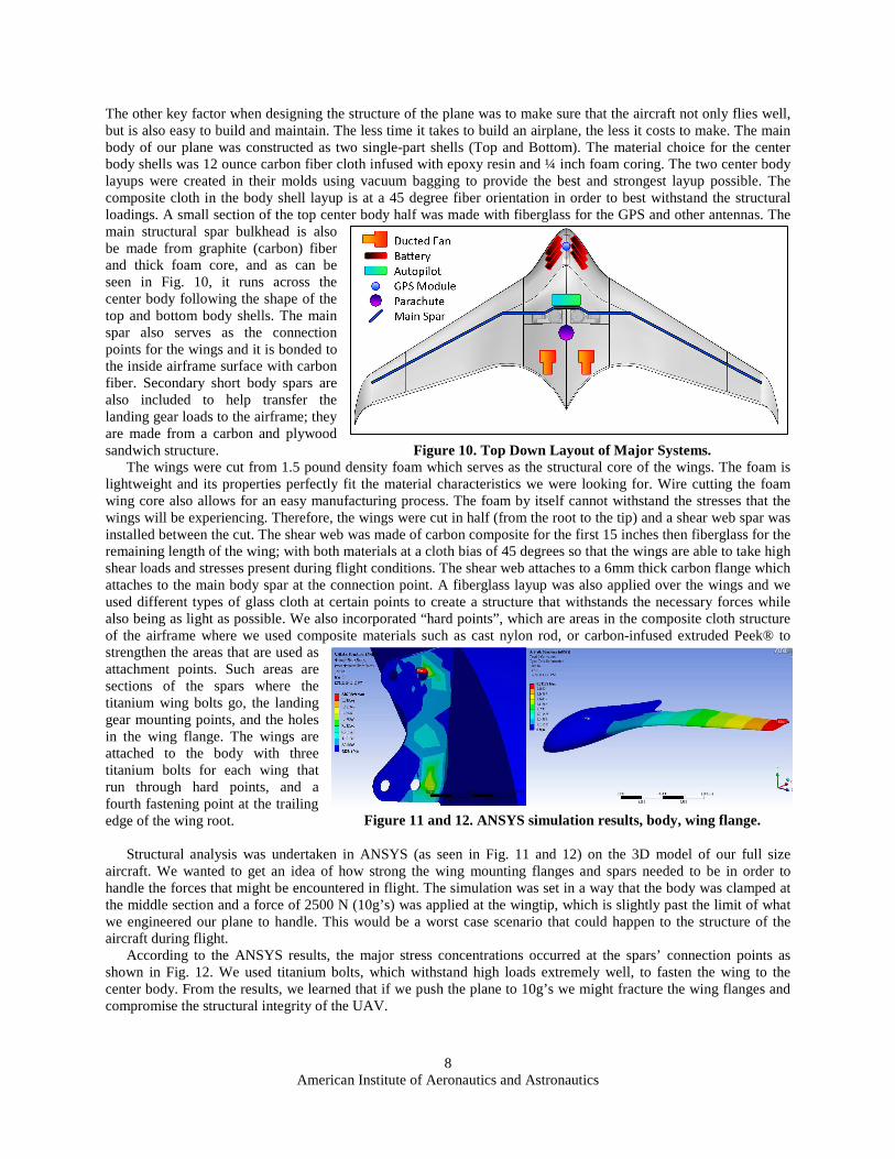
Figure 10. Interior Components Layout.
Figure 11 and 12. ANSYS simulation results, body, wing flange.
The other key factor when designing the structure of the plane was to make sure that the aircraft not only flies well, but is also easy to build and maintain. The less time it takes to build an airplane, the less it costs to make. The main body of our plane was constructed as two single-part shells (Top and Bottom). The material choice for the center body shells was 12 ounce carbon fiber cloth infused with epoxy resin and ¼ inch foam coring. The two center body layups were created in their molds using vacuum bagging to provide the best and strongest layup possible. The composite cloth in the body shell layup is at a 45 degree fiber orientation in order to best withstand the structural loadings. A small section of the top center body half was made with fiberglass for the GPS and other antennas. The main structural spar bulkhead is also be made from graphite (carbon) fiber and thick foam core, and as can be seen in Fig. 10, it runs across the center body following the shape of the top and bottom body shells. The main spar also serves as the connection points for the wings and it is bonded to the inside airframe surface with carbon fiber. Secondary short body spars are also included to help transfer the landing gear loads to the airframe; they are made from a carbon and plywood sandwich structure. Figure 10. Top Down Layout of Major Systems.
The wings were cut from 1.5 pound density foam which serves as the structural core of the wings. The foam is lightweight and its properties perfectly fit the material characteristics we were looking for. Wire cutting the foam wing core also allows for an easy manufacturing process. The foam by itself cannot withstand the stresses that the wings will be experiencing. Therefore, the wings were cut in half (from the root to the tip) and a shear web spar was installed between the cut. The shear web was made of carbon composite for the first 15 inches then fiberglass for the remaining length of the wing; with both materials at a cloth bias of 45 degrees so that the wings are able to take high shear loads and stresses present during flight conditions. The shear web attaches to a 6mm thick carbon flange which attaches to the main body spar at the connection point. A fiberglass layup was also applied over the wings and we used different types of glass cloth at certain points to create a structure that withstands the necessary forces while also being as light as possible. We also incorporated “hard points”, which are areas in the composite cloth structure of the airframe where we used composite materials such as cast nylon rod, or carbon-infused extruded Peek® to strengthen the areas that are used as attachment points. Such areas are sections of the spars where the titanium wing bolts go, the landing gear mounting points, and the holes in the wing flange. The wings are attached to the body with three titanium bolts for each wing that run through hard points, and a fourth fastening point at the trailing edge of the wing root.
Structural analysis was undertaken in ANSYS (as seen in Fig. 11 and 12) on the 3D model of our full size
aircraft. We wanted to get an idea of how strong the wing mounting flanges and spars needed to be in order to handle the forces that might be encountered in flight. The simulation was set in a way that the body was clamped at the middle section and a force of 2500 N (10g’s) was applied at the wingtip, which is slightly past the limit of what we engineered our plane to handle. This would be a worst case scenario that could happen to the structure of the aircraft during flight.
According to the ANSYS results, the major stress concentrations occurred at the spars’ connection points as shown in Fig. 12. We used titanium bolts, which withstand high loads extremely well, to fasten the wing to the center body. From the results, we learned that if we push the plane to 10g’s we might fracture the wing flanges and compromise the structural integrity of the UAV.

American Institute of Aeronautics and Astronautics
9
E. Navigation and Controls One of our main goals for our UAV is to have it fly autonomously over a long distances. We will be using an
autopilot system designed for UAV’s that will enable a manual take off of the aircraft, autonomous flight, and the option of manual or autonomous landing. Our airplane will be controlled by four independent elevons (two on each wing), a rudder on each winglet, and differential thrust via the electric fans. The autopilot can control all the servos and at any time during flight we can switch between manual control and autopilot control. The software operating the autopilot system is an “off the shelf” system by AUAV. It is intended to provide ease of use and not add additional programming tasks to this project. The system allows up to 1000 GPS waypoints to guide our BWB to its destination. The autopilot also has a feature that automatically returns the airplane back to home base in the event that the radio connections are lost. This system also has the capability to use the aileron and elevator inputs for elevon mixing, and it can also use rudder input for throttle mixing. Once takeoff is achieved, changes in coordinates and performance can be made remotely from the ground station and all flight data will also be continuously transmitted to the ground computers.
F. Propulsion System The propulsion system and its integration will affect performance of the BWB very much. For the project’s
particular objective to produce zero emissions and provide a quiet, sturdy, vibration-resistant aircraft, an electric power system was found to be most ideal, either with a propeller or ducted fans. Advanced forms of propulsion, such as turbojets, turbofans, ramjets, and scramjets were superfluous for the project’s given objectives, as the combination of low-costs, zero-emissions, and minimal noise does not directly apply to any of these propulsion systems. Various propulsion systems were considered for performance and practicality, and electric ducted fans have become the preferred option.
For this aircraft we chose two electric ducted fans from Schübeler®, a top of the line German EDF (Electric Ducted Fan) manufacturer. The power plant we chose is the most powerful RC EDF on the market today, and produces 22 lbs. (98N) of thrust, giving our plane 44lbs. (196N) of total thrust. Each fan assembly has an inlet diameter of 5 in. (128mm) and weighs about 3 lbs. (1380g) each. To power the electric motors, we are using 14-cell Lithium Polymer (LiPo) battery packs with a capacity of 8 Ah each, and a 187 Wh/kg energy density. In order to achieve maximum thrust and longer flight times, the motors require two 14-cell packs in parallel each, providing about 7 minutes of full-throttle (although we will not run full throttle the entire flight). With a full battery load, we calculated about a 35 minute flight time at a cruise speed of 80 MPH. The plane will have a top speed of about 125 MPH. Figure 13. Schübeler® 12-blade electric ducted fan.
Sample Endurance Calculation: � LiPo cell:
• Potential: 3.7V • Capacity: 8Ah • Current: 128A continuous, 200A burst
� 14 Cells per Pack � Potential = 51.8V � 2 Packs per motor �
• Capacity = 16Ah • Current = 256A continuous, 400A burst
� Motor draws 140A at full throttle � 16Ah / 140A = .114286h � 6 minutes 52 seconds at Full Throttle

American Institute of Aeronautics and Astronautics
10
In the interest of overall efficiency, the fans are halfway embedded into the fuselage in order to reduce drag. In order to optimize the thrust output of the EDF’s at cruise speed, we designed various inlet ducts for the embedded propulsion system to be used on the UAV. Static and dynamic wind tunnel testing was done on 4 inlet designs, and a podded setup as control. A digital thrust stand was used along with a pitot-static tube inside the wind tunnel to measure thrust force and dynamic pressure at the inlet. Results show that there is a significant difference in dynamic thrust and inlet pressure depending on which inlet design is selected. The optimum design was a diffuser shaped inlet, which reduces the intake velocity right before entering the fan, hence producing the most static and dynamic thrust. Static thrust is the maximum amount of thrust an air breathing engine can theoretically produce. Static Thrust can be calculated by using Eq. (1) below:
(1) Where FStatic is the static thrust, ṁ is the mass flow rate of the air through the fan, and Vexit is the velocity of the
airflow leaving the engine. Dynamic Thrust can be calculated with a similar method using Eq. (2) below:
(2) Where FDynamic is the dynamic thrust and Vinlet is the velocity of the air entering the engine. In Eq. (2), Vinlet is not
equal to zero. Note that FDynamic will always be lower than FStatic. The best way to minimize this decline is to slow down the fluid before it reaches the inlet of the fan, reducing Vinlet. The fluid velocity at a given point is directly related to the dynamic pressure q of the fluid at that point. By measuring the dynamic pressure variations, we can calculate the variations in flow velocity.
(3) Where ρ is the fluid density and V is the free stream fluid velocity. The plot below shows each duct's ability to recover the static thrust (100% thrust) throughout the dynamic range, and Dynamic pressure at the inlet of the fan at various airspeeds. Duct 1 performs the best by slowing down the flow into the fan as it increases the flow area like a NACA-style scoop. It manages to recover 85.3% of the original static thrust, as opposed to the ductless recovery which only leaves 81.2% of the original thrust. All other ducts behaved as expected, with the straight duct 2 following duct 1 closely, and ducts 3 and 4 finishing last, but still performing better than the ductless setup.
Plot 1. Static Thrust Recovery. Table 1. Thrust Improvement at 21 m/s.
Duct1 5.00%
Duct2 3.80%
Duct3 1.60%
Duct 4 1.50%
Control 0.00%

American Institute of Aeronautics and Astronautics
11
Figure 14. Wing Structural Layout.
V. Assembly To begin the build process, we first cut the wing section airfoil shapes from aluminum. These aluminum airfoil
templates were used to wire cut the foam core wing stages. These wing sections were glued together and put on a plywood jig to hold them in the right orientation. The wings were then cut in half to insert a composite shear web spar that runs the length of each wing which is made from carbon at the root section, and fiberglass toward the tip. The wings then received a series of fiberglass layups: 4-ounce cloth on the full top and bottom surfaces, an 11-ounce unidirectional cloth over the leading edge, trailing edge and top and bottom of the shear web, and an additional 9-ounce twill weave cloth over the wing surface near the root area. These cloth variations are what defined the
structural geometry of the wing as seen in Fig. 14. Once the wing is complete the control surfaces were cut from it and flanges and hinges were made for them. We constructed two female molds for the top and bottom halves of the center body. The molds are used to create each of the two carbon composite shell halves of the center body. Both the top and bottom halves of the airplane have a ¼ inch foam core integrated within the carbon. Molding each half of the center body as one full component allows for exceptional structural efficiency and strength.
Once the outer shells are complete, the main composite bulkhead spar and landing gear main spars were constructed. The main bulkhead spar, which is also the wing attachment spar, was molded from 12-ounce carbon cloth with a ½ inch foam core by the use of a male mold. The landing gear spars were made from a plywood and carbon sandwich structure. Hard points for the main wing bolts and landing gear attachments were molded into their respective spars and the spars were fitted to the center body. At this point we began testing the individual components and subsystems of the airplane, and began integrating them into the airframe in their respective locations. The small hatches were then made in the skin of the center body as to leave access to each of the internal components. We then sealed the upper and lower halves of the plane together and began ground testing.
VI. Conclusion This project is a combination of a diverse set of minds focused on one goal. This plane combines knowledge of
modern aeronautics, improvement on them, and future innovation. The ultimate goal is to revolutionize the way we fly around the globe; to be more efficient, and smarter, with how we fly. Carrying more while being more efficient is the way of the future, and we want to be at the forefront of this aeronautical advancement. For once you have tasted flight you will forever walk the earth with your eyes turned skywards, for there you have been, and there you will always long to return – Leonardo da Vinci.
VII. References Electronic Publications 1Kathy Barnstorff, NASA Langley Research Center, “The X-48B Blended Wing Body,” http://www.nasa.gov/vision/earth/improvingflight/x48b.html Computer Software
2SOLIDWORKS Software Package, Ver. 2008 Microware, Dassault systems 1995-2007 3ANSYS software package, Ver 12.0 4Fluent and Gambit software package
Articles 5Wings, April 1999, Vol. 29, No. 2, Sentry Magazines, Granada Hills, CA, pp. 8-19.