Embed Size (px)
Citation preview
User's GuideSWAU085E–July 2011–Revised September 2015
WiLink™ WLAN IP Real-Time Tuning Tool (RTTT)
This user's guide describes the TI RTTT software application that operates, tests, debugs, and calibratesthe Wi-Fi® IP during development of WL127x, WL128x, and WL18xx TI wireless connectivity chipsets.This guide describes the RTTT modes of operation, connection and firmware download steps, and how touse the graphical user interface (GUI) to transmit, receive, and manipulate WLAN packets.
Contents1 Requirements ................................................................................................................ 3
1.1 System Requirements.............................................................................................. 31.2 Configuration Requirements....................................................................................... 3
2 Installation .................................................................................................................... 43 Modes of Operation ......................................................................................................... 4
3.1 Serial Port Mode .................................................................................................... 53.2 USB Over Android Debug Bridge (ADB) Mode ................................................................. 53.3 Operational Mode................................................................................................... 6
4 Connection and Firmware Download ..................................................................................... 64.1 Register Reads and Writes ........................................................................................ 84.2 Power Mode Menu.................................................................................................. 84.3 Antenna Mode Menu ............................................................................................... 9
5 TX Tab ....................................................................................................................... 115.1 TX Packets Section ............................................................................................... 115.2 TX Tab Overall Output Power Area............................................................................. 125.3 TX Tab Tones Area ............................................................................................... 125.4 TX Duty Cycle Configuration..................................................................................... 135.5 Output Power Test on the WiLink 8 Device.................................................................... 14
6 RX Tab....................................................................................................................... 156.1 RX Statistics Area ................................................................................................. 156.2 Sensitivity Measurements ........................................................................................ 15
Appendix A Terms and Abbreviations......................................................................................... 17
List of Figures
1 RTTT Icon .................................................................................................................... 42 RT^3 Main Working Window ............................................................................................... 43 Settings Area With Serial Port Selected .................................................................................. 54 Settings Area With USB Over ADB Mode Selected..................................................................... 55 Settings Area With Operational Mode Selected ......................................................................... 66 RT^3 Main Working Window After Connection and Firmware Download ............................................ 67 Selecting the Firmware Files to Download ............................................................................... 78 Downloading Firmware Message .......................................................................................... 79 Packet Types for Channel 7................................................................................................ 810 Read and Write Registers ................................................................................................. 811 Power Mode Menu........................................................................................................... 912 Antenna Mode Area of the RT^3 Window ................................................................................ 913 TI Module WL1837 Block Diagram ...................................................................................... 1014 TX Tab Display ............................................................................................................. 11
1SWAU085E–July 2011–Revised September 2015 WiLink™ WLAN IP Real-Time Tuning Tool (RTTT)Submit Documentation Feedback
Copyright © 2011–2015, Texas Instruments Incorporated
www.ti.com
15 Overall Output Power Area ............................................................................................... 1216 TX Tones Area ............................................................................................................. 1217 Duty Cycle Control ......................................................................................................... 1318 WLAN 18xx FW Tab ....................................................................................................... 1419 RX Tab....................................................................................................................... 1520 RX GUI ...................................................................................................................... 16
List of Tables
1 Antenna Mode Supported Configuration.................................................................................. 92 TX Parameters.............................................................................................................. 113 20-MHz BW Rates ......................................................................................................... 134 20-MHz and 40-MHz BW Rates.......................................................................................... 135 Terms and Abbreviations.................................................................................................. 17
2 WiLink™ WLAN IP Real-Time Tuning Tool (RTTT) SWAU085E–July 2011–Revised September 2015Submit Documentation Feedback
Copyright © 2011–2015, Texas Instruments Incorporated
www.ti.com Requirements
1 Requirements
1.1 System RequirementsThe RTTT requires the following hardware and software:• PC running Pentium® II (minimum requirements)• Operating systems: Windows® 2000, Windows XP, Windows 7• Serial communication port (RS-232) or USB port with UART-to-USB adapter (to enable the RS232
interface on the WiLink 8.0 IC, see the WL18xx Hardware Integration Users Guide [SWRU437])• For WLAN TX validation, standard RF equipment (such as a power meter, spectrum analyzer, vector
signal analyzer, or a combined tester such as Litepoint™ IQxel™) for TX output power, WLAN mask,and EVM measurements.
• For WLAN RX validation, a vector signal generator to generate WLAN packets for the IC to analyze.
Debug and calibration tools for WLAN and Bluetooth® require four UART ports. The most efficient way todrive these ports to the PC is to use a UART-to-USB converter (not included in the wireless toolspackage). TI recommends using the WL18XXCOM82SDMMC adapter with the TI WL1837MODCOM8Imodule or WL1835MODCOM8B module on the COM8 board.
NOTE: Multiple UART-to-USB adapters are available on the market, such as the FTDI Chip™development modules.
1.2 Configuration RequirementsThe RTTT application for the WiLink 8 WLAN NLCP package release requires the latest versions of thefollowing configuration files:• WiLink 8 WLAN firmware• WiLink 8 WLAN .ini files• WL128x firmware:
– wl128x-fw-4-mr.bin– wl128x-fw-4-sr.bin– wl128x-fw-4-plt.bin– WL128x INI files
• WL127x firmware:– wl127x-fw-4-mr.bin– wl127x-fw-4-sr.bin– wl127x-fw-4-plt.bin– WL127x INI files
The installation files are located in the directory named Wireless Tools at the installation path configuredduring installation. By default, the files are located at the following path:
C:\Program Files (x86)\Texas Instruments\Wireless Tools
NOTE: Throughout this document, the directory in which the installation files reside is referred to asthe Installation directory.
3SWAU085E–July 2011–Revised September 2015 WiLink™ WLAN IP Real-Time Tuning Tool (RTTT)Submit Documentation Feedback
Copyright © 2011–2015, Texas Instruments Incorporated
Installation www.ti.com
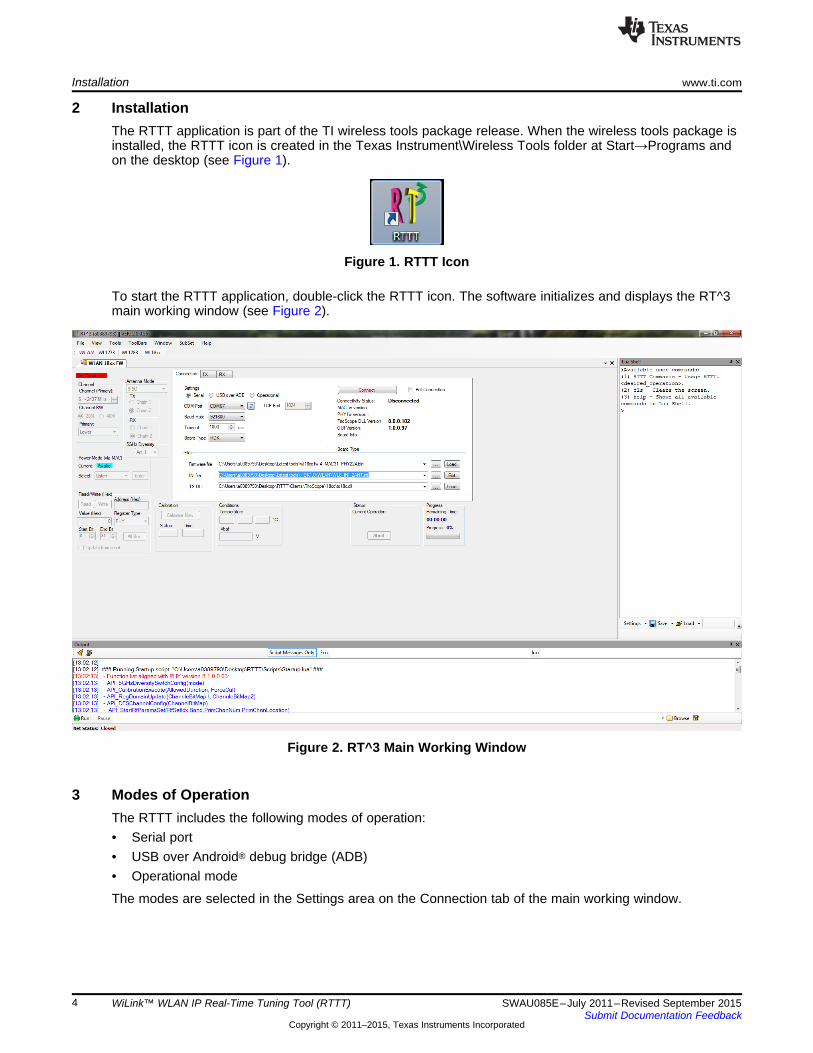
2 InstallationThe RTTT application is part of the TI wireless tools package release. When the wireless tools package isinstalled, the RTTT icon is created in the Texas Instrument\Wireless Tools folder at Start→Programs andon the desktop (see Figure 1).
Figure 1. RTTT Icon
To start the RTTT application, double-click the RTTT icon. The software initializes and displays the RT^3main working window (see Figure 2).
Figure 2. RT^3 Main Working Window
3 Modes of OperationThe RTTT includes the following modes of operation:• Serial port• USB over Android® debug bridge (ADB)• Operational mode
The modes are selected in the Settings area on the Connection tab of the main working window.
4 WiLink™ WLAN IP Real-Time Tuning Tool (RTTT) SWAU085E–July 2011–Revised September 2015Submit Documentation Feedback
Copyright © 2011–2015, Texas Instruments Incorporated
www.ti.com Modes of Operation
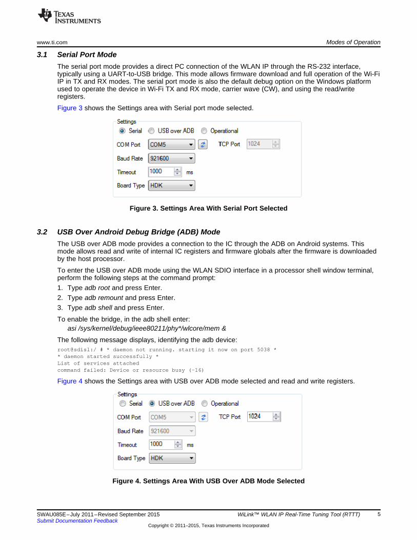
3.1 Serial Port ModeThe serial port mode provides a direct PC connection of the WLAN IP through the RS-232 interface,typically using a UART-to-USB bridge. This mode allows firmware download and full operation of the Wi-FiIP in TX and RX modes. The serial port mode is also the default debug option on the Windows platformused to operate the device in Wi-Fi TX and RX mode, carrier wave (CW), and using the read/writeregisters.
Figure 3 shows the Settings area with Serial port mode selected.
Figure 3. Settings Area With Serial Port Selected
3.2 USB Over Android Debug Bridge (ADB) ModeThe USB over ADB mode provides a connection to the IC through the ADB on Android systems. Thismode allows read and write of internal IC registers and firmware globals after the firmware is downloadedby the host processor.
To enter the USB over ADB mode using the WLAN SDIO interface in a processor shell window terminal,perform the following steps at the command prompt:1. Type adb root and press Enter.2. Type adb remount and press Enter.3. Type adb shell and press Enter.
To enable the bridge, in the adb shell enter:asi /sys/kernel/debug/ieee80211/phy*/wlcore/mem &
The following message displays, identifying the adb device:root@sdisl:/ # * daemon not running. starting it now on port 5038 ** daemon started successfully *List of services attachedcommand failed: Device or resource busy (-16)
Figure 4 shows the Settings area with USB over ADB mode selected and read and write registers.
Figure 4. Settings Area With USB Over ADB Mode Selected
5SWAU085E–July 2011–Revised September 2015 WiLink™ WLAN IP Real-Time Tuning Tool (RTTT)Submit Documentation Feedback
Copyright © 2011–2015, Texas Instruments Incorporated
Modes of Operation www.ti.com
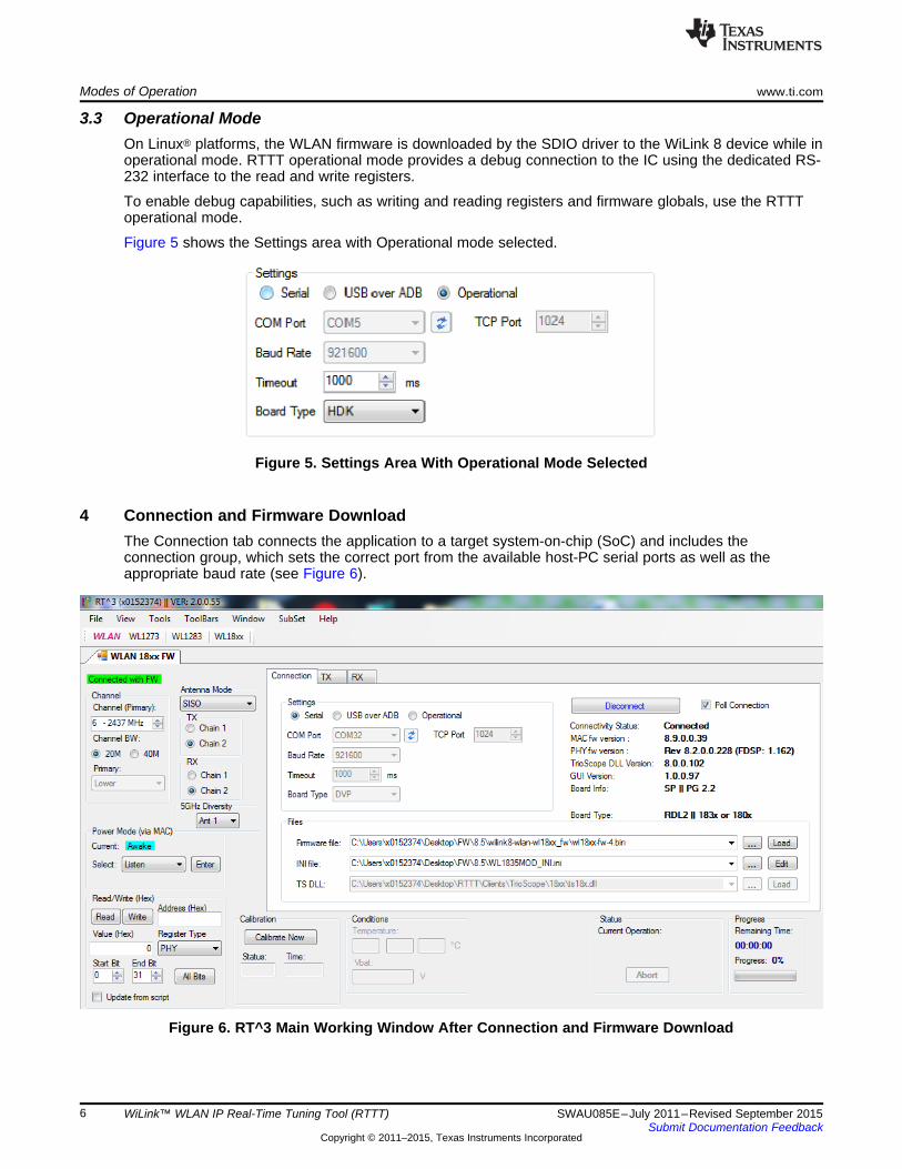
3.3 Operational ModeOn Linux® platforms, the WLAN firmware is downloaded by the SDIO driver to the WiLink 8 device while inoperational mode. RTTT operational mode provides a debug connection to the IC using the dedicated RS-232 interface to the read and write registers.
To enable debug capabilities, such as writing and reading registers and firmware globals, use the RTTToperational mode.
Figure 5 shows the Settings area with Operational mode selected.
Figure 5. Settings Area With Operational Mode Selected
4 Connection and Firmware DownloadThe Connection tab connects the application to a target system-on-chip (SoC) and includes theconnection group, which sets the correct port from the available host-PC serial ports as well as theappropriate baud rate (see Figure 6).
Figure 6. RT^3 Main Working Window After Connection and Firmware Download
6 WiLink™ WLAN IP Real-Time Tuning Tool (RTTT) SWAU085E–July 2011–Revised September 2015Submit Documentation Feedback
Copyright © 2011–2015, Texas Instruments Incorporated
www.ti.com Connection and Firmware Download
To connect the RTTT application to the SoC, perform the following steps:1. In the Settings area of the Connection tab, set the COM port and baud rate fields.
NOTE: The default baud rate is 921600 but can be updated to 3M.
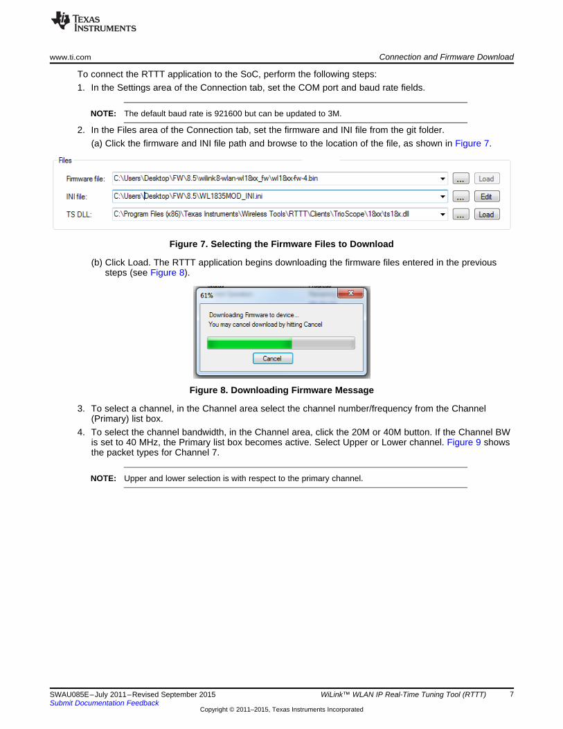
2. In the Files area of the Connection tab, set the firmware and INI file from the git folder.(a) Click the firmware and INI file path and browse to the location of the file, as shown in Figure 7.
Figure 7. Selecting the Firmware Files to Download
(b) Click Load. The RTTT application begins downloading the firmware files entered in the previoussteps (see Figure 8).
Figure 8. Downloading Firmware Message
3. To select a channel, in the Channel area select the channel number/frequency from the Channel(Primary) list box.
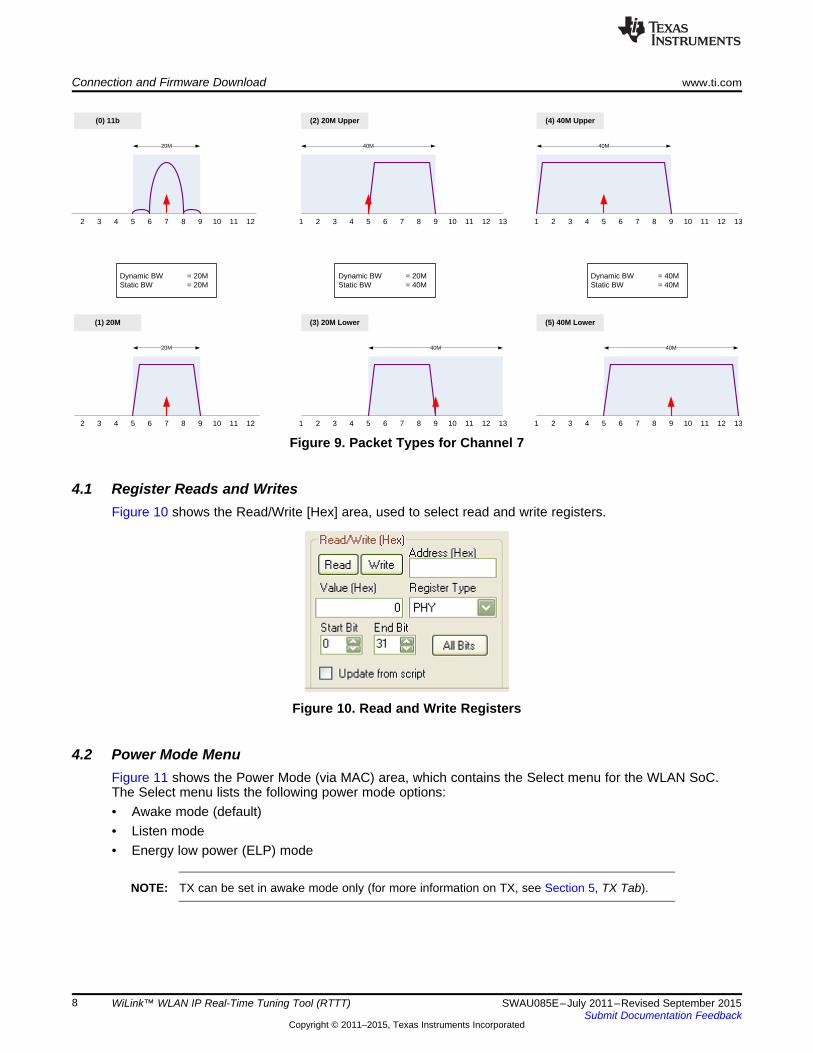
4. To select the channel bandwidth, in the Channel area, click the 20M or 40M button. If the Channel BWis set to 40 MHz, the Primary list box becomes active. Select Upper or Lower channel. Figure 9 showsthe packet types for Channel 7.
NOTE: Upper and lower selection is with respect to the primary channel.
7SWAU085E–July 2011–Revised September 2015 WiLink™ WLAN IP Real-Time Tuning Tool (RTTT)Submit Documentation Feedback
Copyright © 2011–2015, Texas Instruments Incorporated
(0) 11b
5 6 7 82 3 4 119 10
20M
(1) 20M
20M
(2) 20M Upper
40M
Dynamic BW = 20MStatic BW = 20M
Dynamic BW = 20MStatic BW = 40M
Dynamic BW = 40MStatic BW = 40M
(3) 20M Lower
40M
(4) 40M Upper
40M
(5) 40M Lower
40M
12 5 6 7 82 3 4 119 10 121 5 6 7 82 3 4 119 10 121
5 6 7 82 3 4 119 10 121
13 13
13 5 6 7 82 3 4 119 10 121 135 6 7 82 3 4 119 10 12
Connection and Firmware Download www.ti.com
Figure 9. Packet Types for Channel 7
4.1 Register Reads and WritesFigure 10 shows the Read/Write [Hex] area, used to select read and write registers.
Figure 10. Read and Write Registers
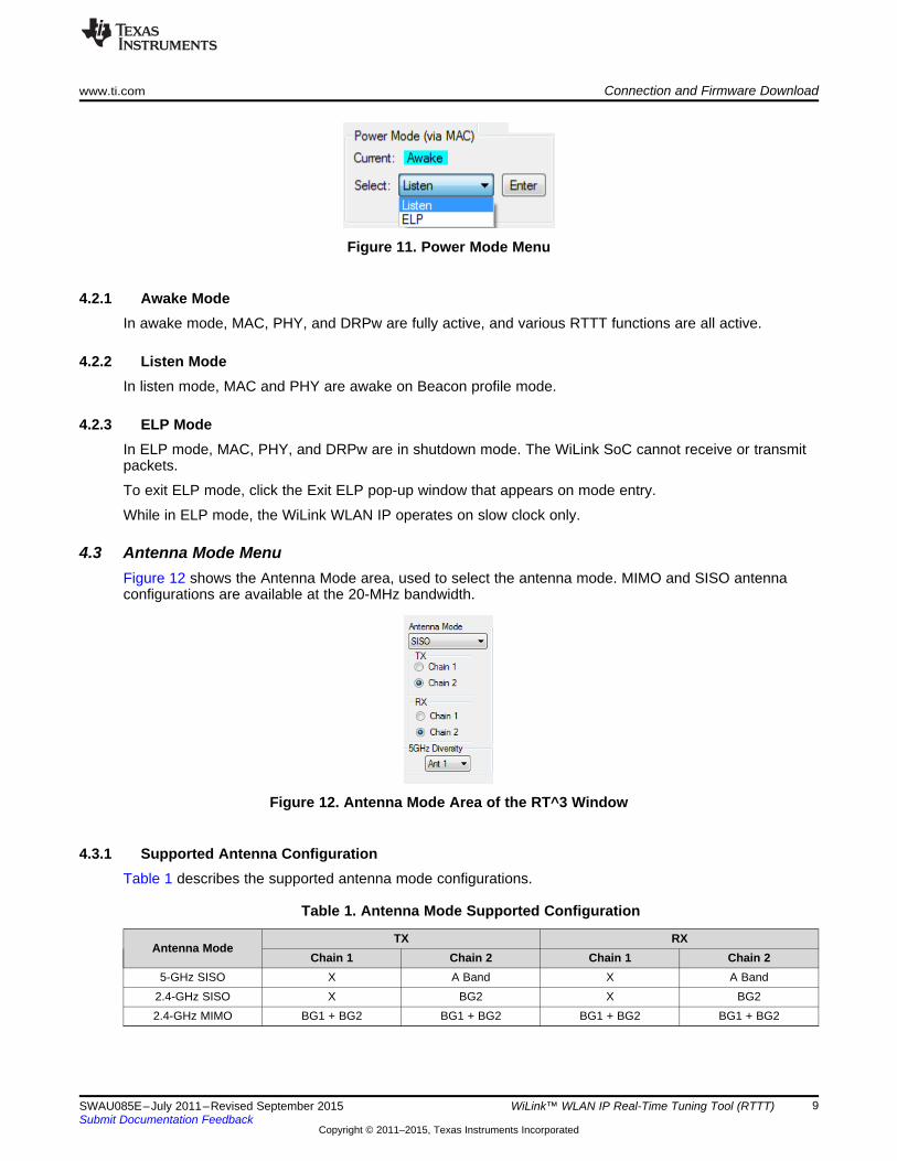
4.2 Power Mode MenuFigure 11 shows the Power Mode (via MAC) area, which contains the Select menu for the WLAN SoC.The Select menu lists the following power mode options:• Awake mode (default)• Listen mode• Energy low power (ELP) mode
NOTE: TX can be set in awake mode only (for more information on TX, see Section 5, TX Tab).
8 WiLink™ WLAN IP Real-Time Tuning Tool (RTTT) SWAU085E–July 2011–Revised September 2015Submit Documentation Feedback
Copyright © 2011–2015, Texas Instruments Incorporated
www.ti.com Connection and Firmware Download
Figure 11. Power Mode Menu
4.2.1 Awake ModeIn awake mode, MAC, PHY, and DRPw are fully active, and various RTTT functions are all active.
4.2.2 Listen ModeIn listen mode, MAC and PHY are awake on Beacon profile mode.
4.2.3 ELP ModeIn ELP mode, MAC, PHY, and DRPw are in shutdown mode. The WiLink SoC cannot receive or transmitpackets.
To exit ELP mode, click the Exit ELP pop-up window that appears on mode entry.
While in ELP mode, the WiLink WLAN IP operates on slow clock only.
4.3 Antenna Mode MenuFigure 12 shows the Antenna Mode area, used to select the antenna mode. MIMO and SISO antennaconfigurations are available at the 20-MHz bandwidth.
Figure 12. Antenna Mode Area of the RT^3 Window
4.3.1 Supported Antenna ConfigurationTable 1 describes the supported antenna mode configurations.
Table 1. Antenna Mode Supported Configuration
TX RXAntenna Mode
Chain 1 Chain 2 Chain 1 Chain 25-GHz SISO X A Band X A Band
2.4-GHz SISO X BG2 X BG22.4-GHz MIMO BG1 + BG2 BG1 + BG2 BG1 + BG2 BG1 + BG2
9SWAU085E–July 2011–Revised September 2015 WiLink™ WLAN IP Real-Time Tuning Tool (RTTT)Submit Documentation Feedback
Copyright © 2011–2015, Texas Instruments Incorporated
RNR
VIO
ZigBee COEX I/F
PMM
AC
/PH
Y
RFTST
32kHz
WLAN: SDIO
BT: UART
WRF1
WRF2
BTRF
BG2
BT
BG1
MA
C/P
HY
BT EN
WLAN EN
VBAT
WRFA
Aband5GHz DPDT
D
D
F
RF_ANT1
RF_ANT2
RNR
26M TCXO
26MHz EXT TCXO
2.4GHz SPDT
Connection and Firmware Download www.ti.com
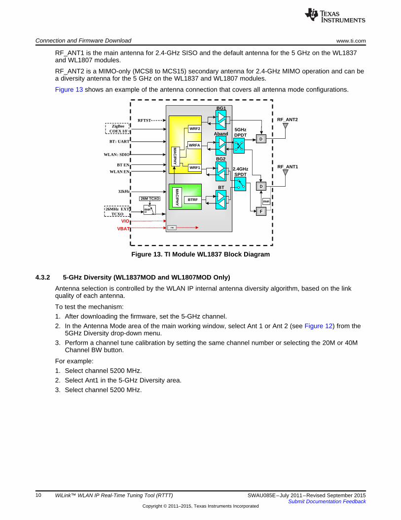
RF_ANT1 is the main antenna for 2.4-GHz SISO and the default antenna for the 5 GHz on the WL1837and WL1807 modules.
RF_ANT2 is a MIMO-only (MCS8 to MCS15) secondary antenna for 2.4-GHz MIMO operation and can bea diversity antenna for the 5 GHz on the WL1837 and WL1807 modules.
Figure 13 shows an example of the antenna connection that covers all antenna mode configurations.
Figure 13. TI Module WL1837 Block Diagram
4.3.2 5-GHz Diversity (WL1837MOD and WL1807MOD Only)Antenna selection is controlled by the WLAN IP internal antenna diversity algorithm, based on the linkquality of each antenna.
To test the mechanism:1. After downloading the firmware, set the 5-GHz channel.2. In the Antenna Mode area of the main working window, select Ant 1 or Ant 2 (see Figure 12) from the
5GHz Diversity drop-down menu.3. Perform a channel tune calibration by setting the same channel number or selecting the 20M or 40M
Channel BW button.
For example:1. Select channel 5200 MHz.2. Select Ant1 in the 5-GHz Diversity area.3. Select channel 5200 MHz.
10 WiLink™ WLAN IP Real-Time Tuning Tool (RTTT) SWAU085E–July 2011–Revised September 2015Submit Documentation Feedback
Copyright © 2011–2015, Texas Instruments Incorporated
www.ti.com TX Tab
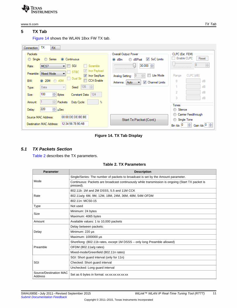
5 TX TabFigure 14 shows the WLAN 18xx FW TX tab.
Figure 14. TX Tab Display
5.1 TX Packets SectionTable 2 describes the TX parameters.
Table 2. TX Parameters
Parameter DescriptionSingle/Series: The number of packets to broadcast is set by the Amount parameter.
Mode Continuous: Packets are broadcast continuously while transmission is ongoing (Start TX packet ispressed).802.11b: 1M and 2M DSSS, 5.5 and 11M CCK
Rate 802.11a/g: 6M, 9M, 12M, 18M, 24M, 36M, 48M, 54M OFDM802.11n: MCS0-15
Type Not usedMinimum: 24 bytes
SizeMaximum: 4065 bytes
Amount Available values: 1 to 10,000 packetsDelay between packets:
Delay Minimum: 220 µsMaximum: 1000000 µsShort/long: (802.11b rates, except 1M DSSS – only long Preamble allowed)
Preamble OFDM (802.11a/g rates)Mixed-mode/Greenfield (802.11n rates)SGI: Short guard interval (only for 11n)
SGI Checked: Short guard intervalUnchecked: Long guard interval
Source/Destination MAC Set as 6 bytes in format: xx:xx:xx:xx:xx:xxAddress
11SWAU085E–July 2011–Revised September 2015 WiLink™ WLAN IP Real-Time Tuning Tool (RTTT)Submit Documentation Feedback
Copyright © 2011–2015, Texas Instruments Incorporated
TX Tab www.ti.com
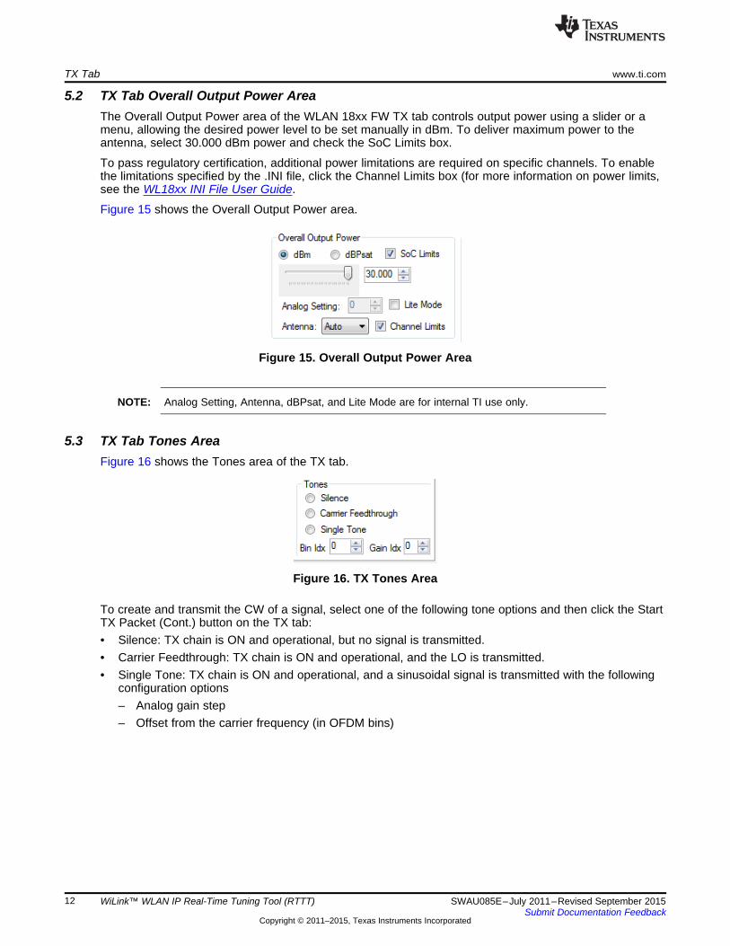
5.2 TX Tab Overall Output Power AreaThe Overall Output Power area of the WLAN 18xx FW TX tab controls output power using a slider or amenu, allowing the desired power level to be set manually in dBm. To deliver maximum power to theantenna, select 30.000 dBm power and check the SoC Limits box.
To pass regulatory certification, additional power limitations are required on specific channels. To enablethe limitations specified by the .INI file, click the Channel Limits box (for more information on power limits,see the WL18xx INI File User Guide.
Figure 15 shows the Overall Output Power area.
Figure 15. Overall Output Power Area
NOTE: Analog Setting, Antenna, dBPsat, and Lite Mode are for internal TI use only.
5.3 TX Tab Tones AreaFigure 16 shows the Tones area of the TX tab.
Figure 16. TX Tones Area
To create and transmit the CW of a signal, select one of the following tone options and then click the StartTX Packet (Cont.) button on the TX tab:• Silence: TX chain is ON and operational, but no signal is transmitted.• Carrier Feedthrough: TX chain is ON and operational, and the LO is transmitted.• Single Tone: TX chain is ON and operational, and a sinusoidal signal is transmitted with the following
configuration options– Analog gain step– Offset from the carrier frequency (in OFDM bins)
12 WiLink™ WLAN IP Real-Time Tuning Tool (RTTT) SWAU085E–July 2011–Revised September 2015Submit Documentation Feedback
Copyright © 2011–2015, Texas Instruments Incorporated
www.ti.com TX Tab
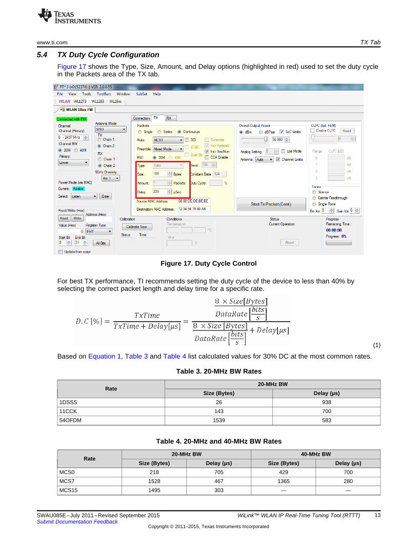
5.4 TX Duty Cycle ConfigurationFigure 17 shows the Type, Size, Amount, and Delay options (highlighted in red) used to set the duty cyclein the Packets area of the TX tab.
Figure 17. Duty Cycle Control
For best TX performance, TI recommends setting the duty cycle of the device to less than 40% byselecting the correct packet length and delay time for a specific rate.
(1)
Based on Equation 1, Table 3 and Table 4 list calculated values for 30% DC at the most common rates.
Table 3. 20-MHz BW Rates
20-MHz BWRate
Size (Bytes) Delay (µs)1DSSS 26 93811CCK 143 70054OFDM 1539 583
Table 4. 20-MHz and 40-MHz BW Rates
20-MHz BW 40-MHz BWRate
Size (Bytes) Delay (µs) Size (Bytes) Delay (µs)MCS0 218 705 429 700MCS7 1528 467 1365 280MCS15 1495 303 — —
13SWAU085E–July 2011–Revised September 2015 WiLink™ WLAN IP Real-Time Tuning Tool (RTTT)Submit Documentation Feedback
Copyright © 2011–2015, Texas Instruments Incorporated
TX Tab www.ti.com
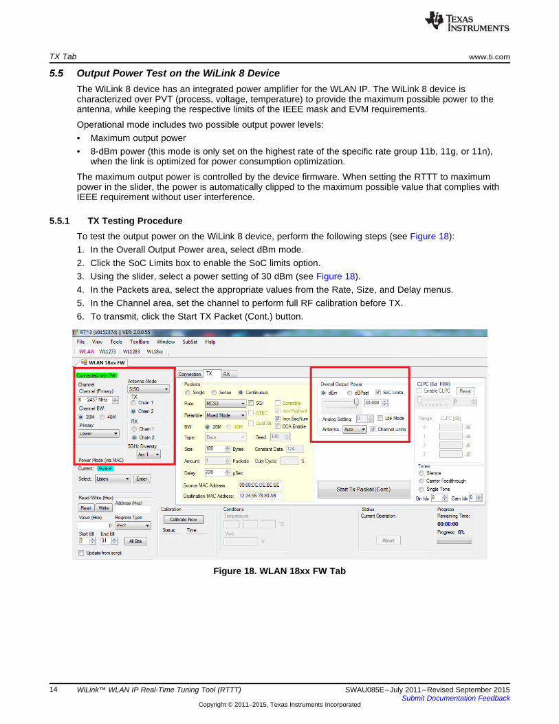
5.5 Output Power Test on the WiLink 8 DeviceThe WiLink 8 device has an integrated power amplifier for the WLAN IP. The WiLink 8 device ischaracterized over PVT (process, voltage, temperature) to provide the maximum possible power to theantenna, while keeping the respective limits of the IEEE mask and EVM requirements.
Operational mode includes two possible output power levels:• Maximum output power• 8-dBm power (this mode is only set on the highest rate of the specific rate group 11b, 11g, or 11n),
when the link is optimized for power consumption optimization.
The maximum output power is controlled by the device firmware. When setting the RTTT to maximumpower in the slider, the power is automatically clipped to the maximum possible value that complies withIEEE requirement without user interference.
5.5.1 TX Testing ProcedureTo test the output power on the WiLink 8 device, perform the following steps (see Figure 18):1. In the Overall Output Power area, select dBm mode.2. Click the SoC Limits box to enable the SoC limits option.3. Using the slider, select a power setting of 30 dBm (see Figure 18).4. In the Packets area, select the appropriate values from the Rate, Size, and Delay menus.5. In the Channel area, set the channel to perform full RF calibration before TX.6. To transmit, click the Start TX Packet (Cont.) button.
Figure 18. WLAN 18xx FW Tab
14 WiLink™ WLAN IP Real-Time Tuning Tool (RTTT) SWAU085E–July 2011–Revised September 2015Submit Documentation Feedback
Copyright © 2011–2015, Texas Instruments Incorporated
www.ti.com RX Tab
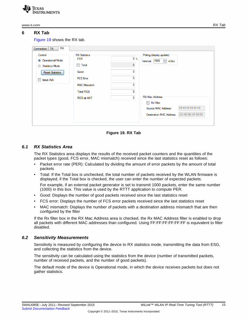
6 RX TabFigure 19 shows the RX tab.
Figure 19. RX Tab
6.1 RX Statistics AreaThe RX Statistics area displays the results of the received packet counters and the quantities of thepacket types (good, FCS error, MAC mismatch) received since the last statistics reset as follows:• Packet error rate (PER): Calculated by dividing the amount of error packets by the amount of total
packets• Total: If the Total box is unchecked, the total number of packets received by the WLAN firmware is
displayed; if the Total box is checked, the user can enter the number of expected packets.For example, if an external packet generator is set to transmit 1000 packets, enter the same number(1000) in this box. This value is used by the RTTT application to compute PER.
• Good: Displays the number of good packets received since the last statistics reset• FCS error: Displays the number of FCS error packets received since the last statistics reset• MAC mismatch: Displays the number of packets with a destination address mismatch that are then
configured by the filter
If the Rx filter box in the RX Mac Address area is checked, the Rx MAC Address filter is enabled to dropall packets with different MAC addresses than configured. Using FF:FF:FF:FF:FF:FF is equivalent to filterdisabled.
6.2 Sensitivity MeasurementsSensitivity is measured by configuring the device to RX statistics mode, transmitting the data from ESG,and collecting the statistics from the device.
The sensitivity can be calculated using the statistics from the device (number of transmitted packets,number of received packets, and the number of good packets).
The default mode of the device is Operational mode, in which the device receives packets but does notgather statistics.
15SWAU085E–July 2011–Revised September 2015 WiLink™ WLAN IP Real-Time Tuning Tool (RTTT)Submit Documentation Feedback
Copyright © 2011–2015, Texas Instruments Incorporated
RX Tab www.ti.com
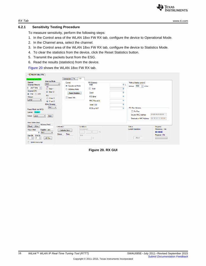
6.2.1 Sensitivity Testing ProcedureTo measure sensitivity, perform the following steps:1. In the Control area of the WLAN 18xx FW RX tab, configure the device to Operational Mode.2. In the Channel area, select the channel.3. In the Control area of the WLAN 18xx FW RX tab, configure the device to Statistics Mode.4. To clear the statistics from the device, click the Reset Statistics button.5. Transmit the packets burst from the ESG.6. Read the results (statistics) from the device.
Figure 20 shows the WLAN 18xx FW RX tab.
Figure 20. RX GUI
16 WiLink™ WLAN IP Real-Time Tuning Tool (RTTT) SWAU085E–July 2011–Revised September 2015Submit Documentation Feedback
Copyright © 2011–2015, Texas Instruments Incorporated
Appendix ASWAU085E–July 2011–Revised September 2015
Terms and Abbreviations
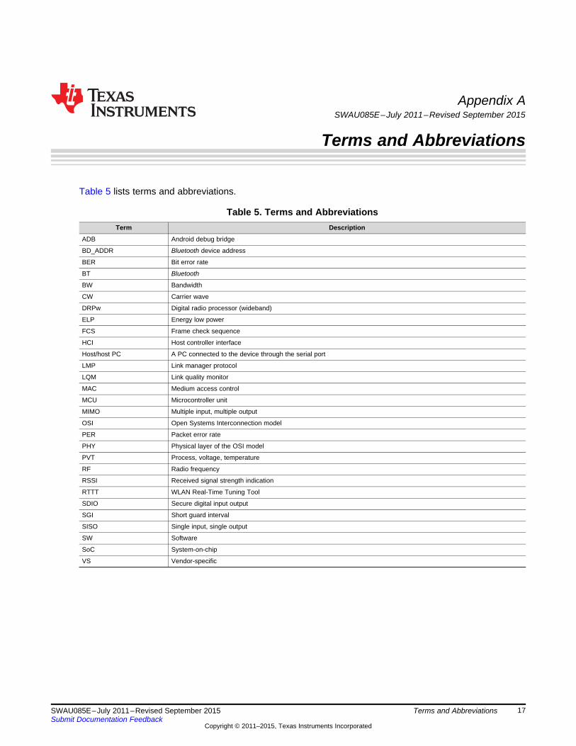
Table 5 lists terms and abbreviations.
Table 5. Terms and AbbreviationsTerm Description
ADB Android debug bridge
BD_ADDR Bluetooth device address
BER Bit error rate
BT Bluetooth
BW Bandwidth
CW Carrier wave
DRPw Digital radio processor (wideband)
ELP Energy low power
FCS Frame check sequence
HCI Host controller interface
Host/host PC A PC connected to the device through the serial port
LMP Link manager protocol
LQM Link quality monitor
MAC Medium access control
MCU Microcontroller unit
MIMO Multiple input, multiple output
OSI Open Systems Interconnection model
PER Packet error rate
PHY Physical layer of the OSI model
PVT Process, voltage, temperature
RF Radio frequency
RSSI Received signal strength indication
RTTT WLAN Real-Time Tuning Tool
SDIO Secure digital input output
SGI Short guard interval
SISO Single input, single output
SW Software
SoC System-on-chip
VS Vendor-specific
17SWAU085E–July 2011–Revised September 2015 Terms and AbbreviationsSubmit Documentation Feedback
Copyright © 2011–2015, Texas Instruments Incorporated
Revision History www.ti.com
Revision History
Changes from D Revision (January 2014) to E Revision ............................................................................................... Page
• Changed organization of user's guide .................................................................................................. 1• Deleted Rev 0.1............................................................................................................................ 1• Changed Section 1.1, System Requirements ......................................................................................... 3• Added Section 1.2, Configuration Requirements ..................................................................................... 3• Added Section 2, Installation ............................................................................................................ 4• Changed Figure 2 ......................................................................................................................... 4• Added Section 3, Modes of Operation ................................................................................................. 4• Deleted Drop Down Menus section ..................................................................................................... 5• Changed Section 4, Connection and Firmware Download .......................................................................... 6• Changed path of Rttt.exe in Section 4, Connection and Firmware Download .................................................... 6• Changed Figure 6 ......................................................................................................................... 6• Changed step 2 in Section 4, Connection and Firmware Download ............................................................... 7• Changed Figure 11........................................................................................................................ 9• Changed Table 1 .......................................................................................................................... 9• Changed RF_ANT2 range from MCS12 to MCS15 in Table 1 .................................................................... 10• Changed Section 5, TX Tab............................................................................................................ 11• Deleted TX Dialog Box and RT3 Operation sections ............................................................................... 11• Changed minimum delay from 20 µs and DSSS from 2M in Table 2............................................................. 11• Changed Section 5.2, TX Tab Overall Output Power Area ........................................................................ 12• Changed Figure 17 ...................................................................................................................... 13• Changed Equation 1..................................................................................................................... 13• Changed calculated values from 40% DC in Section 5.4, TX Duty Cycle Configuration....................................... 13• Changed Table 3 ........................................................................................................................ 13• Changed Table 4 ........................................................................................................................ 13• Changed Figure 18 ...................................................................................................................... 14• Changed Section 6, RX Tab ........................................................................................................... 15• Changed Figure 19 ...................................................................................................................... 15• Changed Section 6.2, Sensitivity Measurements.................................................................................... 15• Changed Figure 20 ...................................................................................................................... 16• Added Appendix A, Terms and Abbreviations ....................................................................................... 17
WiLink is a trademark of Texas Instruments.Bluetooth is a registered trademark of Bluetooth SIG, Inc.FTDI Chip is a trademark of Future Technology Devices; International Limited.Android is a registered trademark of Google, Inc.Pentium is a registered trademark of Intel Corporation.Linux is a registered trademark of Linus Torvalds.Litepoint, IQxel are trademarks of LitePoint Corporation.Windows is a registered trademark of Microsoft Inc.Wi-Fi is a registered trademark of Wi-Fi Alliance.All other trademarks are the property of their respective owners.
18 Revision History SWAU085E–July 2011–Revised September 2015Submit Documentation Feedback
Copyright © 2011–2015, Texas Instruments Incorporated
IMPORTANT NOTICE
Texas Instruments Incorporated and its subsidiaries (TI) reserve the right to make corrections, enhancements, improvements and otherchanges to its semiconductor products and services per JESD46, latest issue, and to discontinue any product or service per JESD48, latestissue. Buyers should obtain the latest relevant information before placing orders and should verify that such information is current andcomplete. All semiconductor products (also referred to herein as “components”) are sold subject to TI’s terms and conditions of salesupplied at the time of order acknowledgment.TI warrants performance of its components to the specifications applicable at the time of sale, in accordance with the warranty in TI’s termsand conditions of sale of semiconductor products. Testing and other quality control techniques are used to the extent TI deems necessaryto support this warranty. Except where mandated by applicable law, testing of all parameters of each component is not necessarilyperformed.TI assumes no liability for applications assistance or the design of Buyers’ products. Buyers are responsible for their products andapplications using TI components. To minimize the risks associated with Buyers’ products and applications, Buyers should provideadequate design and operating safeguards.TI does not warrant or represent that any license, either express or implied, is granted under any patent right, copyright, mask work right, orother intellectual property right relating to any combination, machine, or process in which TI components or services are used. Informationpublished by TI regarding third-party products or services does not constitute a license to use such products or services or a warranty orendorsement thereof. Use of such information may require a license from a third party under the patents or other intellectual property of thethird party, or a license from TI under the patents or other intellectual property of TI.Reproduction of significant portions of TI information in TI data books or data sheets is permissible only if reproduction is without alterationand is accompanied by all associated warranties, conditions, limitations, and notices. TI is not responsible or liable for such altereddocumentation. Information of third parties may be subject to additional restrictions.Resale of TI components or services with statements different from or beyond the parameters stated by TI for that component or servicevoids all express and any implied warranties for the associated TI component or service and is an unfair and deceptive business practice.TI is not responsible or liable for any such statements.Buyer acknowledges and agrees that it is solely responsible for compliance with all legal, regulatory and safety-related requirementsconcerning its products, and any use of TI components in its applications, notwithstanding any applications-related information or supportthat may be provided by TI. Buyer represents and agrees that it has all the necessary expertise to create and implement safeguards whichanticipate dangerous consequences of failures, monitor failures and their consequences, lessen the likelihood of failures that might causeharm and take appropriate remedial actions. Buyer will fully indemnify TI and its representatives against any damages arising out of the useof any TI components in safety-critical applications.In some cases, TI components may be promoted specifically to facilitate safety-related applications. With such components, TI’s goal is tohelp enable customers to design and create their own end-product solutions that meet applicable functional safety standards andrequirements. Nonetheless, such components are subject to these terms.No TI components are authorized for use in FDA Class III (or similar life-critical medical equipment) unless authorized officers of the partieshave executed a special agreement specifically governing such use.Only those TI components which TI has specifically designated as military grade or “enhanced plastic” are designed and intended for use inmilitary/aerospace applications or environments. Buyer acknowledges and agrees that any military or aerospace use of TI componentswhich have not been so designated is solely at the Buyer's risk, and that Buyer is solely responsible for compliance with all legal andregulatory requirements in connection with such use.TI has specifically designated certain components as meeting ISO/TS16949 requirements, mainly for automotive use. In any case of use ofnon-designated products, TI will not be responsible for any failure to meet ISO/TS16949.
Products ApplicationsAudio www.ti.com/audio Automotive and Transportation www.ti.com/automotiveAmplifiers amplifier.ti.com Communications and Telecom www.ti.com/communicationsData Converters dataconverter.ti.com Computers and Peripherals www.ti.com/computersDLP® Products www.dlp.com Consumer Electronics www.ti.com/consumer-appsDSP dsp.ti.com Energy and Lighting www.ti.com/energyClocks and Timers www.ti.com/clocks Industrial www.ti.com/industrialInterface interface.ti.com Medical www.ti.com/medicalLogic logic.ti.com Security www.ti.com/securityPower Mgmt power.ti.com Space, Avionics and Defense www.ti.com/space-avionics-defenseMicrocontrollers microcontroller.ti.com Video and Imaging www.ti.com/videoRFID www.ti-rfid.comOMAP Applications Processors www.ti.com/omap TI E2E Community e2e.ti.comWireless Connectivity www.ti.com/wirelessconnectivity
Mailing Address: Texas Instruments, Post Office Box 655303, Dallas, Texas 75265Copyright © 2015, Texas Instruments Incorporated