Embed Size (px)
Citation preview

Wideband MIMO antenna withenhanced isolation forwireless communicationapplication
Xinyu Liu1, Muhammad Amin2, and Jiajun Liang3a)1 Central Laboratory for Biomedical Engineering, Shenzhen University,
Shenzhen 518000, Guangdong, China2 School of Physics, University of Electronic Science and Technology of China,
China3 College of Information Engineering, Shenzhen University,
Shenzhen 518060, P.R. China
Abstract: A wideband multiple input multiple output (MIMO) antenna
with enhanced isolation for wireless communication application is presented
in this article. The proposed antenna operates in a wide frequency range of
1.92–6.1GHz, and is suitable for WiMAX, IEEE 802.11a/b/n/g, UMTS,
LTE-2300 and LTE-2500 wireless communications. The MIMO antenna
structure of the proposed antenna consists of two identical radiators with a
small size of 35 × 36mm2 and a novel H-shaped parasitic element, which
is connected to the ground plane of the proposed antenna. The H-shaped
parasitic element helps in enhancing antenna isolation performance between
the two antenna ports. The overall performance of the proposed antenna in
terms of S-parameters, radiation pattern, gain, and envelope correlation
coefficient is investigated and verified through the measurements. The
measured results show that the proposed antenna has attractive properties
such as compact size, the low mutual coupling of less than −15.4 dB, anda low envelope correlation coefficient of less than 0.14 across the whole
operating frequency band. These attractive properties make the proposed
antenna a good candidate for wireless communication application.
Keywords: MIMO, wideband, high isolation
Classification: Microwave and millimeter-wave devices, circuits, and
modules
References
[1] S. K. Menon: “Microstrip patch antenna assisted compact dual-band planarcrossover,” Electronics 6 (2017) 74 (DOI: 10.3390/electronics6040074).
[2] Q. Chen, et al.: “Modulated scattering array antenna for MIMO application,”IEICE Electron. Express 4 (2007) 745 (DOI: 10.1587/elex.4.745).
[3] X. He, et al.: “MIMO antenna with working frequency accompanied isolationcharacteristic,” IEICE Electron. Express 14 (2017) 20170602 (DOI: 10.1587/
© IEICE 2018DOI: 10.1587/elex.15.20180948Received October 15, 2018Accepted October 22, 2018Publicized November 7, 2018Copyedited November 25, 2018
1
LETTER IEICE Electronics Express, Vol.15, No.22, 1–9

elex.14.20170602).[4] Y. Yin, et al.: “A compact planar UWB MIMO antenna using modified ground
stub structure,” IEICE Electron. Express 14 (2017) 20170883 (DOI: 10.1587/elex.14.20170883).
[5] M. Amin, et al.: “A bowtie-shaped MIMO dielectric resonator antenna forWLAN applications,” IEICE Electron. Express 14 (2017) 20170519 (DOI: 10.1587/elex.14.20170519).
[6] S. Shoaib, et al.: “MIMO antennas for mobile handsets,” IEEE AntennasWireless Propag. Lett. 14 (2015) 799 (DOI: 10.1109/LAWP.2014.2385593).
[7] A. Toktas and A. Akdagli: “Wideband MIMO antenna with enhanced isolationfor LTE, WiMAX and WLAN mobile handsets,” IET Electron. Lett. 50 (2014)723 (DOI: 10.1049/el.2014.0686).
[8] H. Wang, et al.: “Wideband tri-port MIMO antenna with compact size anddirectional radiation pattern,” IET Electron. Lett. 50 (2014) 1261 (DOI: 10.1049/el.2014.2291).
[9] J. Ren, et al.: “Compact printed MIMO antenna for UWB applications,” IEEEAntennas Wireless Propag. Lett. 13 (2014) 1517 (DOI: 10.1109/LAWP.2014.2343454).
[10] L. Liu, et al.: “Compact MIMO antenna for portable devices in UWBapplications,” IEEE Trans. Antennas Propag. 61 (2013) 4257 (DOI: 10.1109/TAP.2013.2263277).
[11] K. Rosengren and P.-S. Kildal: “Radiation efficiency correlation diversity gainand capacity of a six-monopole antenna array for a MIMO system: Theory,simulation and measurement in reverberation chamber,” IET Microw. AntennasPropag. 152 (2005) 7 (DOI: 10.1049/ip-map:20045031).
[12] S. Zhang, et al.: “Closely-packed UWB MIMO/diversity antenna withdifferent patterns and polarizations for USB dongle applications,” IEEE Trans.Antennas Propag. 60 (2012) 4372 (DOI: 10.1109/TAP.2012.2207049).
1 Introduction
Multiple-input-multiple-output (MIMO) as a wireless technology, can increase the
channel capacity effectively. MIMO technology has become an essential technique
in most wireless standards such as wireless local area network (WLAN), and
worldwide interoperability for microwave access (WiMAX) [1, 2, 3, 4, 5]. The
MIMO systems are able to simultaneously transmit multiple signals through
spatially parallel channels between isolated multiple antennas. In a MIMO system,
data throughput is substantially increased by the introduction of spatial multi-
plexing gain and diversity gain. Owing to these superior features, recently emerged
mobile communication standards relating to long-term evolution (LTE), worldwide
interoperability for microwave access (WiMAX) and IEEE 802.11a/b/n/g for
wireless local area networks (WLANs) have been incorporated into MIMO
technologies and adapted to handheld mobile applications.
Recently, various MIMO antennas for UWB or WLAN/WiMAX applications
have been reported [6, 7, 8, 9, 10]. However, there are some limitations in their
designs. In [7], the antenna only operates a frequency range of 1.79–3.77GHz,
which is not suitable for WLAN/WiMAX applications. A bandwidth of 51.6%
(2.30–3.90GHz) is achieved in [8], which is not suitable for long-term evolution
(LTE) applications. In [9] and [10], the MIMO antennas are suitable for UWB
© IEICE 2018DOI: 10.1587/elex.15.20180948Received October 15, 2018Accepted October 22, 2018Publicized November 7, 2018Copyedited November 25, 2018
2
IEICE Electronics Express, Vol.15, No.22, 1–9
applications, covering the bandwidth of 3–10.6GHz. According to the author’s
knowledge, by using some certain techniques, a low-frequency operating band can
be achieved from previous designs.
In this paper, a wideband MIMO antenna with enhanced isolation for IEEE
802.11a/b/n/g, WiMAX, UMTS, LTE-2300 and LTE-2500 wireless communica-
tion applications is proposed. The proposed antenna covers the whole three
WiMAX bands (2.30–2.36, 2.50–2.90 and 3.3–3.8GHz), the WLAN bands
(2.40–2.485, 5.15–5.35, 5.725–5.825GHz), the UMTS band (1.92–2170GHz),
and the LTE bands (2300–2400 and 2500–2690GHz). The antenna consists of
two identical symmetrical radiating elements. To mitigate the mutual coupling, a
novel H-shaped parasitic element is added to the ground plane. The antenna is
designed by using a computer-based simulation software namely CST. The details
of the antenna design, simulation and measurement results are presented and
discussed. The optimized physical parameters of the proposed MIMO antenna
are given below.
2 Antenna design and analyze
2.1 Antenna configuration
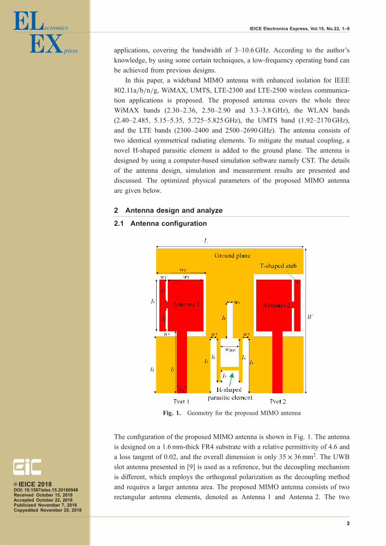
The configuration of the proposed MIMO antenna is shown in Fig. 1. The antenna
is designed on a 1.6mm-thick FR4 substrate with a relative permittivity of 4.6 and
a loss tangent of 0.02, and the overall dimension is only 35 � 36mm2. The UWB
slot antenna presented in [9] is used as a reference, but the decoupling mechanism
is different, which employs the orthogonal polarization as the decoupling method
and requires a larger antenna area. The proposed MIMO antenna consists of two
rectangular antenna elements, denoted as Antenna 1 and Antenna 2. The two
Fig. 1. Geometry for the proposed MIMO antenna
© IEICE 2018DOI: 10.1587/elex.15.20180948Received October 15, 2018Accepted October 22, 2018Publicized November 7, 2018Copyedited November 25, 2018
3
IEICE Electronics Express, Vol.15, No.22, 1–9

antenna elements are placed in parallel and each antenna element is fed by a 50-Ω
microstrip line. To obtain a larger bandwidth, a pair of defected ground structures
(DGSs) are etched. Moreover, another DGS is etched on the ground between the
two ports and an H-shaped parasitic element is added at the same time to further
improve the isolation. Finally, the physical parameters of the proposed antenna are
optimized as follows: W ¼ 36mm, L ¼ 35mm, l ¼ 12mm, l2 ¼ 5mm, l3 ¼15:5mm, l4 ¼ 14mm, l5 ¼ 15mm, l6 ¼ 9mm, l7 ¼ 2mm, l8 ¼ 7mm, w1 ¼ 2mm,
w2 ¼ 8:5mm, w3 ¼ 0:5mm, w4 ¼ 12mm, w5 ¼ 0:5mm, Lf ¼ 16:5mm, wf ¼3mm, wgap ¼ 6mm.
2.2 Design process and parameters optimization
The design process of the proposed MIMO antenna (denoted as Ant 4) is demon-
strated as shown in Fig. 2, including Ant 1 to Ant 4. Fig. 3 shows the correspond-
Fig. 2. Evolution process of the proposed MIMO antenna.
(a) (b)
Fig. 3. Simulated S-parameters of the four antenna configurations.
© IEICE 2018DOI: 10.1587/elex.15.20180948Received October 15, 2018Accepted October 22, 2018Publicized November 7, 2018Copyedited November 25, 2018
4
IEICE Electronics Express, Vol.15, No.22, 1–9

ing simulated S-parameters of the four types of antenna configurations. One can
observe that when the main radiator of Ant1 is consist of a rectangular patch and a
T-shaped stub, only a single resonance mode at 4.93GHz is generated; Ant 2 is
realized by adding a pair of defected ground structures (denoted as DGS 1) to
Ant 1, the reflection coefficient less than −10 dB of Ant 2 covers from 2.3GHz
to 6.1GHz, but the mutual coupling of Ant 2 is just lower than −7 dB across the
whole operating band; Ant 3 is realized by adding a defected ground structure
(denoted as DGS 2) to Ant 2 between the two antenna ports, the reflection
Fig. 4. Simulated surface current distributions of the four antennaconfigurations.
© IEICE 2018DOI: 10.1587/elex.15.20180948Received October 15, 2018Accepted October 22, 2018Publicized November 7, 2018Copyedited November 25, 2018
5
IEICE Electronics Express, Vol.15, No.22, 1–9

coefficient of Ant 3 is almost unchanged (2.18GHz to 6.1GHz), but the isolation
shows a bit better than Ant 2; Finally, the proposed MIMO antenna (Ant 4) is
obtained by adding an H-shaped parasitic element to Ant 3. As can be seen from
Fig. 3(b), the mutual coupling level (S21) is improved greatly, and the reflection
coefficient less than −10 dB of Ant 4 covers from 2.19GHz to 6.1GHz.
To further understand the operation mechanism of the proposed MIMO
antenna, Fig. 4 shows the corresponding simulated surface current distributions
of the four types of antenna configurations (Only Port 1 is excited while Port 2 is
terminated with a matching load). As can be seen from Fig. 4(a), the first antenna
model Ant 1, the currents are mainly concentrating at the T-shaped stub, so that the
resonance mode of Ant 1 is mainly contributed by the T-shaped stub; for the
second antenna model Ant 2, as a pair of defected ground structures (denoted as
DGS 1) are etched, the impedance bandwidth is improved largely, the lower
resonance mode at 2.4GHz is contributed by the narrow gap between the long
side of the main radiator (þy direction) and the DGS 1, the higher resonance mode
at 5.5GHz is mainly contributed by the gap between the short side of the main
radiator (−x direction) and the DGS 1 as well the T-shaped stub; for the third
antenna model Ant 3, the surface current distribution is similar to Ant 2, one
obvious difference is that part of the currents are blocked by the DGS 2, resulting
a small increase in isolation and impedance bandwidth; for the fourth antenna
model Ant 4, the surface current distribution is similar to Ant 2 and Ant 3, but
most of the currents are blocked by the H-shaped parasitic element, which improves
(a) (b)
Fig. 5. Simulated S-parameters when tuning the parameter wgap.
(a) (b)
Fig. 6. Simulated S-parameters when tuning the parameter l6.
© IEICE 2018DOI: 10.1587/elex.15.20180948Received October 15, 2018Accepted October 22, 2018Publicized November 7, 2018Copyedited November 25, 2018
6
IEICE Electronics Express, Vol.15, No.22, 1–9

the isolation greatly by blocking the currents between the two antenna ports, while
the impedance bandwidth is almost kept unchanged.
Fig. 5 shows the simulated S-parameters when tuning the parameter wgap. As
can be seen, it is clear that increasing the wgap from 3mm to 9mm with a step
increment of 3mm can vary the isolation greatly while the reflection coefficients are
kept unchanged, the optimal isolation is obtained when wgap is set to 6mm.
Fig. 6 depicts the simulated S-parameters when tuning the parameter l6. One
can observe that increasing the l6 from 4mm to 12mm with a step increment of
4mm can vary the reflection coefficients of the higher resonant frequencies
(4.7GHz–5.5GHz) while the lower resonant frequencies are almost kept un-
changed; Furthermore, the optimal mutual coupling level (S21) less than
−15.2 dB is obtained over the whole bands when l6 is set to 8mm.
2.3 Fabrication and measurement
The proposed antenna has been fabricated and measured, and its photograph is
shown in Fig. 7. The antenna elements are fed through 50 ohms SMA. The
S-parameters of the proposed antenna were measured by means of a vector network
analyzer, employing a coaxial cable at the desired antenna port and connecting the
others to 50-Ω load.
The simulated and measured S-parameter plots are presented in Fig. 8. It could
be seen that the measured S-parameters are consistent with the simulated results.
Fig. 7. Illustration of the prototyped MIMO antenna
Fig. 8. Simulated and measured S-parameters.
© IEICE 2018DOI: 10.1587/elex.15.20180948Received October 15, 2018Accepted October 22, 2018Publicized November 7, 2018Copyedited November 25, 2018
7
IEICE Electronics Express, Vol.15, No.22, 1–9

The discrepancies between the simulated and measured results may be attributed to
the variations in the geometry, and mismatch of feed probe in the fabrication
process. The proposed prototyped MIMO antenna operates over a frequency range
of about 1.92–6.1GHz with a measured mutual coupling level (S21) less than
−15.4 dB.
The measured peak gain of the proposed antenna across the whole desired band
is depicted in Fig. 9. It can be seen that the minimum gain is about 2.7 dBi at
1.92GHz, and the maximum gain is about 3.8 dBi at 6.1GHz. Therefore, the
proposed antenna exhibits stable gains across the operating bands, which is suitable
for practical applications. Fig. 9 also contains the envelope correlation coefficient
(ECC) which is an important parameter to evaluate the diversity characteristic of a
MIMO system. The envelope correlation coefficient can be calculated from
measured complex radiation pattern as [11]:
ECC ¼
ZZ
4�
½E1ð�; �Þ*E2ð�; �Þ�d�������
������2
ZZ
4�
jE1ð�; �Þj2d�ZZ
4�
jE2ð�; �Þj2d�ð1Þ
where Eið�; �Þ is the complex 3D radiated field pattern for Antenna i (i ¼ 1; 2) and
* denotes the Hermitian product. In general, the lower the ECC level, the higher the
diversity. As can be seen from Fig. 9, the maximum ECC lower than 0.14 across
the whole operating band, and the ECC maintained at 0.06 over most of the
operating band, which means that the antenna design has a good diversity.
Fig. 9. Measured ECC and gain against frequency.
(a) (b)
Fig. 10. Measured radiation patterns: (a) xoz-plane, (b) xoy-plane.
© IEICE 2018DOI: 10.1587/elex.15.20180948Received October 15, 2018Accepted October 22, 2018Publicized November 7, 2018Copyedited November 25, 2018
8
IEICE Electronics Express, Vol.15, No.22, 1–9

Fig. 10 shows the measured two-dimensional radiation patterns of the proposed
antenna for three frequencies of 2.4, 3.5, 5.5GHz. The radiation patterns are similar
to each other, and nearly omnidirectional radiation patterns in the xoz-plane, and a
dipole-like radiation pattern in the xoy-plane. Besides, performances comparison
with several existing antennas in references are listed in Table I, it reveals that the
proposed MIMO antenna does exhibit some advantages in gain, mutual coupling,
bandwidth and ECC.
3 Conclusion
A wideband multiple input multiple output (MIMO) antenna with enhanced
isolation for wireless communication application is presented. The MIMO antenna
structure consists of two identical radiators with a small size of 35 � 36mm2 and a
novel H-shaped parasitic element is connected to the ground plane. By using this
H-shaped parasitic element, a better isolation performance has been achieved
between the two antenna ports. The measured radiation pattern of the antenna
shows nearly omnidirectional radiation and good gain variation as well. Moreover,
the antenna elements have excellent ECC values. Consequently, the results obtained
show that the proposed antenna has attractive properties due to being a compact
size, the low mutual coupling of less than −15.4 dB, and a low envelope correlation
coefficient of less than 0.14 across the whole operating frequency band, making it a
good candidate for wireless communication application.
Table I. Comparison of the proposed antenna and references
[4] [7] [12] This work
Size (mm3) 30 � 40 � 0:8 10 � 17:7 � 1:6 25 � 40 � 1:6 35 � 36 � 1:6
Frequency (GHz) 3.1–10.6 1.79–3.77 3.1–5.15 1.92–6.1
Mutual coupling (dB) <�18 <�13 <�26 <�15:4Minimum gain (dBi) 1.8 2.86 1.5 2.7
ECC <0:06 <0:16 <0:1 <0:14
© IEICE 2018DOI: 10.1587/elex.15.20180948Received October 15, 2018Accepted October 22, 2018Publicized November 7, 2018Copyedited November 25, 2018
9
IEICE Electronics Express, Vol.15, No.22, 1–9