Embed Size (px)
Citation preview
1
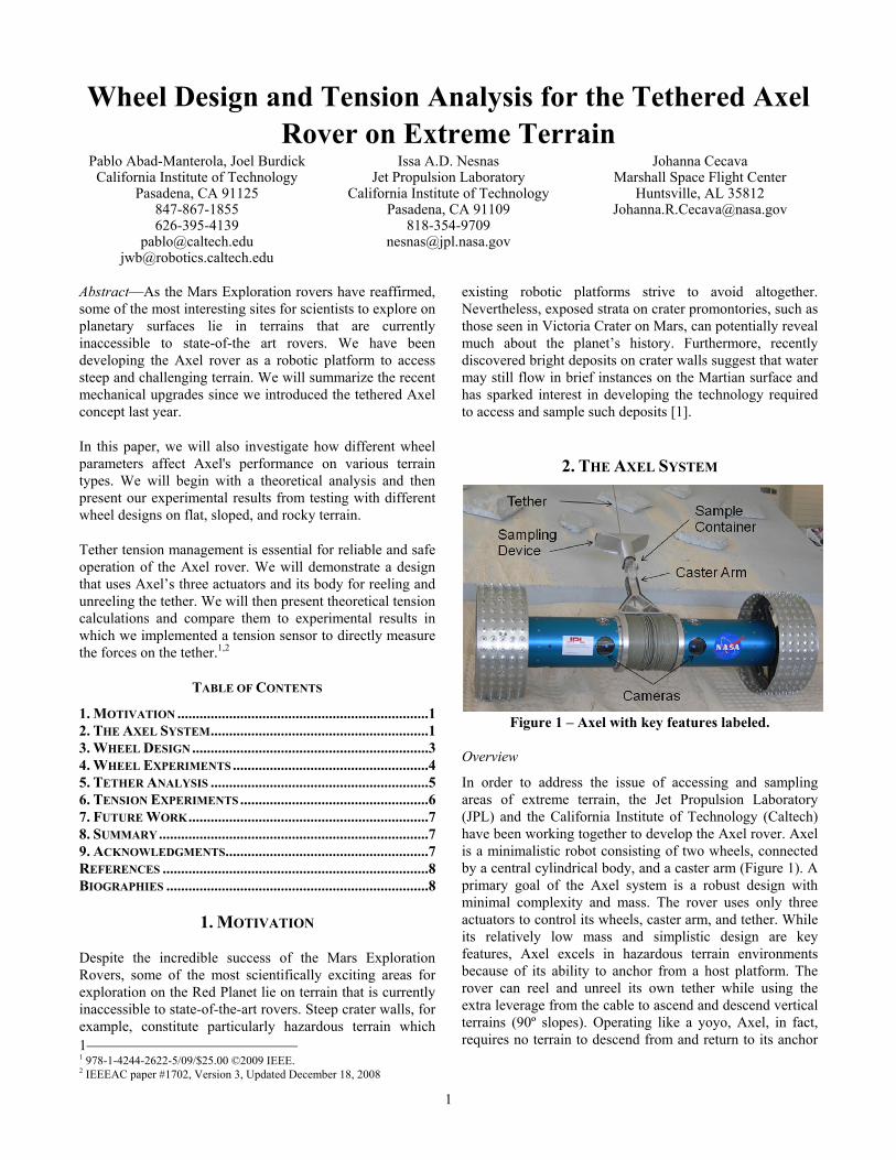
Wheel Design and Tension Analysis for the Tethered Axel Rover on Extreme Terrain
Pablo Abad-Manterola, Joel Burdick California Institute of Technology
Pasadena, CA 91125 847-867-1855 626-395-4139
[email protected] [email protected]
Issa A.D. Nesnas Jet Propulsion Laboratory
California Institute of Technology Pasadena, CA 91109
818-354-9709 [email protected]
Johanna Cecava Marshall Space Flight Center
Huntsville, AL 35812 [email protected]
Abstract—As the Mars Exploration rovers have reaffirmed, some of the most interesting sites for scientists to explore on planetary surfaces lie in terrains that are currently inaccessible to state-of-the art rovers. We have been developing the Axel rover as a robotic platform to access steep and challenging terrain. We will summarize the recent mechanical upgrades since we introduced the tethered Axel concept last year.
In this paper, we will also investigate how different wheel parameters affect Axel's performance on various terrain types. We will begin with a theoretical analysis and then present our experimental results from testing with different wheel designs on flat, sloped, and rocky terrain.
Tether tension management is essential for reliable and safe operation of the Axel rover. We will demonstrate a design that uses Axel’s three actuators and its body for reeling and unreeling the tether. We will then present theoretical tension calculations and compare them to experimental results in which we implemented a tension sensor to directly measure the forces on the tether.1,2
TABLE OF CONTENTS
1. MOTIVATION ....................................................................1 2. THE AXEL SYSTEM...........................................................1 3. WHEEL DESIGN ................................................................3 4. WHEEL EXPERIMENTS .....................................................4 5. TETHER ANALYSIS ...........................................................5 6. TENSION EXPERIMENTS ...................................................6 7. FUTURE WORK.................................................................7 8. SUMMARY.........................................................................7 9. ACKNOWLEDGMENTS.......................................................7 REFERENCES ........................................................................8 BIOGRAPHIES .......................................................................8
1. MOTIVATION
Despite the incredible success of the Mars Exploration Rovers, some of the most scientifically exciting areas for exploration on the Red Planet lie on terrain that is currently inaccessible to state-of-the-art rovers. Steep crater walls, for example, constitute particularly hazardous terrain which 1 1 978-1-4244-2622-5/09/$25.00 ©2009 IEEE. 2 IEEEAC paper #1702, Version 3, Updated December 18, 2008
existing robotic platforms strive to avoid altogether. Nevertheless, exposed strata on crater promontories, such as those seen in Victoria Crater on Mars, can potentially reveal much about the planet’s history. Furthermore, recently discovered bright deposits on crater walls suggest that water may still flow in brief instances on the Martian surface and has sparked interest in developing the technology required to access and sample such deposits [1].
2. THE AXEL SYSTEM
Figure 1 – Axel with key features labeled.
Overview
In order to address the issue of accessing and sampling areas of extreme terrain, the Jet Propulsion Laboratory (JPL) and the California Institute of Technology (Caltech) have been working together to develop the Axel rover. Axel is a minimalistic robot consisting of two wheels, connected by a central cylindrical body, and a caster arm (Figure 1). A primary goal of the Axel system is a robust design with minimal complexity and mass. The rover uses only three actuators to control its wheels, caster arm, and tether. While its relatively low mass and simplistic design are key features, Axel excels in hazardous terrain environments because of its ability to anchor from a host platform. The rover can reel and unreel its own tether while using the extra leverage from the cable to ascend and descend vertical terrains (90º slopes). Operating like a yoyo, Axel, in fact, requires no terrain to descend from and return to its anchor

2
point, enabling it to handle promontories with greater than 90º slopes.
Mission Concept
Since Axel’s own body acts as a winch, the host platform requirements are reduced to a simple fixed mount capable of supporting approximately 25 kg. Thus, this host platform could be a lander, a larger rover, a habitat, or even an astronaut. Once this anchor point has been secured, Axel can descend over cliff walls, navigate through rocky terrain, take images, collect soil samples, and then return by reeling the tether. Figure 2 portrays a hypothetical scenario in which Axel is deployed from the Mars Science Laboratory (MSL). Scheduled for launch in 2011, MSL is a good example of a larger host platform that could potentially carry Axel as a method of sampling in extreme terrain [2].
Figure 2 – Proposed mission concept overlaid on false
color image of Victoria Crater. Note that the rover graphics are not to scale.
There are several advantages to using this tethered approach as part of the mission concept. First, the risk of descending into craters is isolated to the tethered rover. If a failure were to occur in the Axel platform, the host platform could detach the tether and continue with any other mission objectives it might have. Because Axel can operate with or without a tether, depending on the nature of the failure, Axel may be able to continue its exploration to some level. Second, since Axel itself is the winch, the tether is laid over the terrain as the rover descends, and then the tether is collected as the rover returns to the host platform. In contrast to a situation in which the winch is mounted on the host, our approach minimizes shear on the tether from rocks and cliff faces. Finally, the anchor and tether system allows Axel to travel over cliff promontories with slope angles greater than 90 degrees, which would not be possible with an independent wheeled rover.
Prototype System and Upgrades
Axel’s cylindrical body houses and protects all of its hardware and electronic components. Computations are performed by a 700 MHz PC/104 main processor board with 128 MB of RAM. The hard drive, a 2 GB IDE solid state drive running Ubuntu Linux, is used to store images and other data that Axel collects. The wheels are each driven by a 30V Servodisc drive motor geared down with a harmonic drive. The entire system is controlled remotely with a laptop via Wi-Fi connection.
Over the past year, several modifications have been made to Axel to increase its capabilities and improve its performance. First and foremost, the external power supply and power cable have been eliminated entirely. Axel is now powered by a 24V lithium polymer battery contained inside of the central cylinder. Axel can be driven continuously for one hour with its 4.2 Ah battery before it needs to be recharged.
Because of the steep slopes and free-hanging maneuvers, previous experiments with Axel required the use of a safety tether to protect the rover from being severely damaged if it were ever to fall. We recently implemented a safety circuit that brakes the caster motor in case of a sudden loss of power. While it does not stop the motor completely, the circuit ensures a slow and controlled descent, eliminating the need for a safety tether.
Stereo cameras had to be relocated from the central section of the original non-tethered Axel to the location shown in Figure 1 to make room for the tether. Two PointGrey 1024x768 color Firewire cameras were installed with a 25 cm baseline. Fujinon lenses with 105º field-of-view were used to capture images and provide Axel’s operator with the ability to drive the rover while remaining outside of its direct line of sight. In tumbling mode, Axel’s central cylinder and, hence, cameras rotate about its long axis producing images at different pitch angles. Tumbling mode is primarily used to reel and unreel the tether during ascent and descent. It may also be used on flat terrain to slacken or tighten the tether. To control the pitch at which images are acquired when operated in this mode, we use an inertial measurement unit (IMU) to trigger image acquisition. As a result, consecutive images can be acquired at the same pitch when the rover is tele-operated. In this way, we can correlate images taken with the cameras to body angle measurements from the IMU to produce an image map which is more intuitive for the operator.
We installed a MicroStrain 3DM-GX1 IMU at the center of the central cylinder. In addition to the three-axis accelerometers that provide the two tilt angles for the rover, the three-axis gyroscopes will be used to estimate the rover’s pose.
Finally, we have improved Axel’s sampling device from the prototype we used in the previous year. The original device consisted of a cylinder mounted directly onto the boom.

3
Sampling was performed on the slope by angling the mouth of the tube into the soil, unreeling the tether, and allowing gravity to pull Axel’s boom into the ground and pushing soil into the sampling device. Experiments demonstrated that this method worked well only for clumpy sand and at slope angles greater than 10 degrees. Our most recent sampling device features a T-shaped tube mounted on the end of the boom (Figure 3). After pointing the boom into the ground, we can rotate Axel in place in either direction to collect a sample. This method works well for loose sand and on slopes all the way down to 0 degrees. The device also has a removable collection tube at the bottom of the “T” where the host platform rover could potentially remove the sample for scientific analysis.
Figure 3 – Axel taking a sample by pointing the caster arm into the ground and turning in place. Sand enters through the sides of the “T” and collects at the bottom.
3. WHEEL DESIGN
Figure 4 – Free-body diagram of a wheel travelling over
a rock just as it loses contact with the ground. Descending crater walls and navigating over loose sediment and rocky terrain persists as a difficult challenge for rovers, whose performance in these scenarios depends greatly on
the type of wheels they carry. Thus, we have exerted some effort on the design and optimization of Axel’s wheels for our particular goal of extreme terrain exploration. A simplified physics model will now be presented in order to help build a better understanding of how wheels drive over obstacles.
While obstacle traversal is greatly improved by the use of a tether, Axel must be able to operate independently while on flat ground. Therefore, in order to focus particularly on wheel optimization, the tether input is excluded from the analysis.
Figure 4 represents the force diagram of a wheel just as it loses contact with the ground after encountering an obstacle. For simplicity, we will represent the obstacles as circles even though their shape in the field can be much more complicated. The wheel makes contact with the obstacle at a point along its rim θ radians from the vertical, μ is the coefficient of friction between the wheel and the obstacle, and τ represents the input torque applied to the wheel by the motor. Summing the forces and moments, we have:
θsinmgfmaFx −−==∑ (1)
∑ −== θcos0 mgnFy (2)
∑ −−== τα frIM c (3)
Note that 2
21 mrI = for a circular disc, and that
ra−=α and nf μ< for the wheel to travel without
slipping. After rearranging and solving, we find that for the wheel to have a positive acceleration in the x-direction, quantitatively 0>a for 2/0 πθ <≤ , two conditions must be met:
θτ sinmgr> (4)
θμ tan> (5)
Immediately we notice that as θ approaches 2/π , the coefficient of friction must tend toward infinity if the wheel is to make it over the obstacle. In other words, without the aid of a tether, the wheel will not be able to surpass obstacles in which the contact point is one-half of the wheel diameter from the ground or higher.
Traditional wheels, therefore, are fundamentally limited in terms of their performance over obstacles. With slight modification, however, we can redirect the forces on the

4
wheel in our favor. Figure 5 presents a free-body diagram of a wheel with 5 “paddles” mounted equidistant along the edge. The motion that this wheel provides can be considered a hybrid of rolling and walking. The symbols are the same as in the previous example except that we also include the length of the paddle, l . From Newton’s second law we have:
∑ +−== θcos0 mgfFx (6)
∑ −== θsinmgnmaFy (7)
∑ ++−== )( lrnIM c τα (8)
Figure 5 – Force diagram of a paddle-wheel as it
encounters an obstacle and just as it leaves the ground. For simplicity, we will assume that the paddles are lightweight and do not contribute significantly to the wheel’s moment of inertia. In addition, in order to travel
over the obstacle without slipping, note that lr
a+
−=α
and once again nf μ< . After simplifying on the
condition that 0>a for 2/0 πθ <≤ , we find two conditions must be met:
θτ sin)( lrmg +> (9)
( ))(2sin
cos)(22
22
lrmgrlrrmg
++++>
τθθμ (10)
Note in this case that the coefficient of friction depends on the inverse of the input torque. As a result, the lower-bound on μ can be made arbitrarily small if τ is unbounded above. Furthermore, the lower-bound on μ approaches zero as the
contact point angle, θ, approaches 2/π . Thus, with a paddle-wheel design, for a small increase in the required torque, it actually becomes easier to travel over obstacles without slipping, especially as the contact point angle increases.
If we allow the paddle-wheel to slip in the x-direction, the equations of motion become:
∑ +−== θcosmgfmaF xx (11)
∑ −== θsinmgnmaF yy (12)
∑ ++−=⎟⎟⎠
⎞⎜⎜⎝
⎛+
−== )(
2
2
lrnlr
amrIM yc τα (13)
Here we simplify on the condition that 0>xa for
2/0 πθ <≤ while noting that nf μ= . It turns out
that the input torque requirement is the same as in the no-slip case and that the coefficient of friction requirement becomes:
θμ cot< (14)
Hence for small angles it is easy to travel over obstacles while slipping. As the contact point angle increases, one can expect the paddle-wheel to stop slipping and switch to the previous equations of motion. Note that this is in contrast to the traditional wheel, which cannot overcome an obstacle while slipping.
In summary, a simplified physics model of the paddle-wheel predicts that it will perform much better than a traditional wheel at higher contact point angles. At smaller angles, we expect that the paddle-wheel will perhaps overcome the obstacle while it slips along the paddle.
A rigorous analysis of the performance of Axel’s wheels over deformable terrain is beyond the scope of this paper and will be the subject of future investigation. The research is particularly important for Axel because low-cohesion soils are characteristic of the extreme terrain environments encountered on Mars. Relevant work in this field can be found in the references section [3,4,5].
4. WHEEL EXPERIMENTS Experiments conducted in the summer of 2007 with the original spiked wheels demonstrated Axel’s capability to drive untethered on flat ground and over rocks not exceeding 1/3 of the wheel diameter [6]. In the summer of

5
2008, different wheel designs were implemented in order to gauge their performance on sandy and rocky terrain.
In an attempt to increase the size of the obstacles that Axel could easily travel over, 26” Hakkapeliitta W240 mountain bike tires were mounted onto the frame (Figure 6). These were more than double the diameter of the original spiked wheels, and so we expected much better performance over obstacles. Nevertheless, experiments carried out in the mini Mars Yard at JPL did not confirm our hypothesis. A typical pattern would be for the wheel to approach the obstacle, and then Axel would involuntarily turn in place while the wheel slipped without gripping. Finally, after the wheel no longer faced the obstacle, Axel would proceed forward, having simply managed to turn around the obstacle without travelling over it.
Figure 6 – Axel with mountain bike tires.
Experiments were conducted with the tires fully inflated, half inflated, and with very low inflation. For all three cases, however, the results were very similar and no significant difference was noted. Even over small rocks that the original 12” wheels could traverse easily, the new tires did not seem to grip effectively. In only a few instances did the wheels find a grip and make it over the obstacles.
The results of the mountain bike tire experiments reaffirmed the importance of the spikes on the original wheels. In order to emphasize this point and optimize the spike design, we constructed a 5-paddle wheel design that was mentioned previously (Figure 7). The paddles were approximately 3” long and were mounted onto the original 12” diameter hub.
Despite their awkward motion while moving over flat ground, these wheels were incredibly effective at surpassing obstacles. For the first time, Axel was able to traverse rocks that were 70% - 80% of the wheel diameter, including the length of the paddles. The rover also managed to climb a 12” step obstacle without any difficulty. And finally, Axel successfully ascended a 25-30 degree slope over packed dirt without the aid of a tether.
Figure 7 – Axel with the paddle-wheels.
The success over obstacles comes intuitively at a loss of efficiency while travelling on flat ground. Forthcoming experiments will attempt to quantify exactly how much less efficient the paddle-wheel design is over the traditional wheel. Additionally, future iterations will attempt to optimize the paddle shape, length, and spacing for the application of extreme terrain exploration.
5. TETHER ANALYSIS
Figure 8 - Two-dimensional free-body diagram of
tethered Axel on a slope.
Axel can descend over crater promontories and ascend steep slopes on loose sediment primarily because of its unique ability to manage its own tether. Tensile strength, resistance to shear, mass, and diameter are all important factors when considering the tether that is best suited for any particular application. A careful examination of wire rope products available on the market will reveal that tensile strength is primarily a function of the diameter of the cable, which, in turn, corresponds to its overall mass. Robustness to shearing, on the other hand, is more difficult to quantify and
6
depends mostly on the cable’s finish and coating. Thus, we will begin with a theoretical analysis of the tensile forces experienced by the tether, which helped us to determine the minimum breaking strength required to support the Axel rover.
Figure 8 offers a two-dimensional free-body diagram of a tethered Axel on a slope. In a static analysis, the equations of motion are:
∑ +−−== ssstx nfTF θθθ sincoscos0 (15)
mgnfTF sssty −++==∑ θθθ cossinsin0 (16)
∑ −+−+== wsscctscct rfLTLTM )cos(sin)sin(cos0 θθθθθθ
(17)
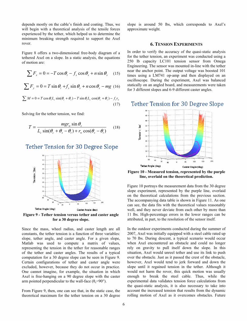
Solving for the tether tension, we find:
)cos()sin(sin
tswtscc
sw
rLmgrT
θθθθθθ
−+−+= (18)
Figure 9 - Tether tension versus tether and caster angle
for a 30 degree slope.
Since the mass, wheel radius, and caster length are all constants, the tether tension is a function of three variables: slope, tether angle, and caster angle. For a given slope, Matlab was used to compute a matrix of values, representing the tension in the tether for reasonable ranges of the tether and caster angles. The results of a typical computation for a 30 degree slope can be seen in Figure 9. Certain configurations of tether and caster angle were excluded, however, because they do not occur in practice. One cannot imagine, for example, the situation in which Axel is free-hanging on a 90 degree slope with the caster arm pointed perpendicular to the wall-face (θc=90°).
From Figure 9, then, one can see that, in the static case, the theoretical maximum for the tether tension on a 30 degree
slope is around 50 lbs, which corresponds to Axel’s approximate weight.
6. TENSION EXPERIMENTS In order to verify the accuracy of the quasi-static analysis for the tether tension, an experiment was conducted using a 250 lb capacity LC101 tension sensor from Omega Engineering. The sensor was mounted in-line with the tether near the anchor point. The output voltage was boosted 101 times using a LM741 op-amp and then displayed on an oscilloscope. During the experiment, Axel was balanced statically on an angled board, and measurements were taken for 3 different slopes and 6-9 different caster angles.
Figure 10 - Measured tension, represented by the purple
line, overlaid on the theoretical prediction. Figure 10 portrays the measurement data from the 30 degree slope experiment, represented by the purple line, overlaid on the theoretical calculations from the previous section. The accompanying data table is shown in Figure 11. As one can see, the data fits with the theoretical values reasonably well, and they never deviate from each other by more than 11 lbs. High-percentage errors in the lower ranges can be attributed, in part, to the resolution of the sensor itself.
In the outdoor experiments conducted during the summer of 2007, Axel was initially equipped with a steel cable rated up to 70 lbs. During descent, a typical scenario would occur when Axel encountered an obstacle and could no longer rely on gravity to pull itself down the slope. In this situation, Axel would unreel tether and use its link to push over the obstacle. Just as it passed the crest of the obstacle, however, Axel would tend to jerk forward and down the slope until it regained tension in the tether. Although it would not harm the rover, this quick motion was usually enough to break the steel cable. Thus, while the experimental data validates tension force calculations from the quasi-static analysis, it is also necessary to take into account the increased tension that results from the dynamic rolling motion of Axel as it overcomes obstacles. Future

7
work will provide the full characterization of the tension on the tether and a means for continuously measuring the tension of the tether to improve rover control.
Figure 11 – Data from tension experiments for Axel on a
30 degree slope.
More recent testing in Washington, DC this past year employed 1/8 inch diameter, nylon-coated, 7x7 strand core steel cable rated up to 920 lbs. This cable was tested extensively with more than 100 descent-sample-ascent cycles. These tests have demonstrated the cable’s long-term degradation to shearing, especially in areas subjected to sharp obstacle corners. Although the cable never broke, ruptures in the nylon coating were a frequent occurrence. Nevertheless, this cable performed much better than anticipated and was overrated for the current Axel.
We have decided to try a smaller cable in order to reduce the weight and increase the amount of tether we can successfully mount on Axel. Employing a safety factor of at least 2 from the quasi-static tension calculation, we have chosen an uncoated tether with a 200 lb capacity. Experiments with this new tether will be forthcoming.
7. FUTURE WORK Short-term improvements on the Axel rover will include increasing the Wi-Fi connection range, installing more robust motor controllers, improving the paddle-wheel design, and performing more experiments with the new 200 lb tether. In the long-term, we hope to develop a more sophisticated computational model involving the complex wheel-soil interaction. The model would then allow us to program Axel with a robust control algorithm, allowing the rover to complete its goals autonomously.
8. SUMMARY Some of the most scientifically exciting areas for exploration on Mars lie on terrain that is currently inaccessible to rovers. Craters are particularly interesting because of bright new deposits that have recently been found. JPL and Caltech have been working together to develop the Axel rover for extreme terrain excursions and
sampling. Axel is a minimalistic, two-wheeled robot designed to be deployed via tether from a larger host platform.
Using a theoretical analysis of different wheel designs followed by an experimental validation in the JPL mini Mars Yard, we have shown that modifying the wheel design can provide Axel with a much greater capability for traversing rocky terrain and climbing moderate slopes without a tether. We have also demonstrated the effectiveness of the paddle-wheel design in travelling over obstacles greater than one-half of the wheel diameter. Having performed a quasi-static tension analysis and tension experiments, we have concluded that a 200 lb steel cable will safely support Axel while minimizing the tether’s mass and volume. Tests on this new tether will be performed shortly. All these experiments were enabled by upgrades to the avionics and power system that allow us to operate Axel with the desired single tether, thus eliminating the need for both an external power cable and an additional safety tether.
Future work on the Axel rover will involve more sophisticated modeling and developing a control algorithm for autonomous behavior.
9. ACKNOWLEDGMENTS We would like to thank current and former members of the Axel team: Jeffrey Edlund for the design of the rover avionics, the development of its tele-operated control software and for his overall support to the project during the design and implementation phases; Dr. Srikanth Saripalli for the development of the vision capture software, Thomas Oliver for the development of the paddle wheels, Kevin Noertker for the development of the sampling device, Dan Helmick for mechanical design of the original Axel, Raymond Christian for machining the original rover, Nam Nguygen, Chun-Che Peng, Hung Tran and Ed Barlow for development of rasping devices and for mechanical and avionics upgrades. We would also like to thank former students: Damon Sisk, Isaac Vaughn, Samuel Irwin, Chad Kessen, and Lauren Lyons for their contribution to the hardware and software for the rover.
Additionally, we would also like to express our sincere appreciation for our sponsors in the Exploration Systems Mission Directorate and Solar Systems Exploration program: Dr. Christopher Moore, Dr. Satish Khanna, Dr. Tsun Yee Yan, Dr. Jim Cutts, and Dr. Kim Reh. We would also like to acknowledge the support of Dr. Samad Hayati, Dr. Richard Volpe and Dr. Gabriel Udomkesmalee of JPL.
This work is a joint collaboration between Caltech and the Jet Propulsion Laboratory. The work was done at the Jet Propulsion Laboratory, California Institute of Technology,

8
under contract to the National Aeronautics and Space Administration.
REFERENCES [1] http://www.nasa.gov/mission_pages/mars/images/pia0 90
27.html
[2] http://mars.jpl.nasa.gov/msl/overview/
[3] H. Shibly, K. Iagnemma, S. Dubowsky, “An Equivalent Soil Mechanics Formulation for Rigid Wheels in Deformable Terrain, with Application to Planetary Exploration Rovers,” Journal of Terramechanics, vol. 42, no. 1, pp. 1-13, January 2005.
[4] G. Scott, G. Meirion-Griffith, C. Saaj, El Moxey, “A Comparative Study of the Deformation of Planetary Soils under Tracked and Legged Rovers,” AIAA Space Conference & Exposition, September 2008.
[5] G. Bekker, “Theory of Land Locomotion: the Mechanics of Vehicle Mobility,” University of Michigan Press, Ann Arbor, 1956.
[6] I. Nesnas, P. Abad-Manterola, J. Edlund, J.W. Burdick, “Axel Mobility Platform for Steep Terrain Excursions and Planetary Sampling,” IEEE Aerospace Conference, 1-8 March 2008.
BIOGRAPHIES Pablo Abad-Manterola earned a B.S. in Mechanical Engineering and a minor in Mathematics from Stanford University in 2006 before obtaining his M.S. from Caltech in 2008. He is currently pursuing a Ph.D. in Mechanical Engineering under the guidance of Dr. Joel Burdick and with the support of a fellowship from the National Science Foundation. His research interests
include autonomous sensor-based motion planning and multi-robot cooperation.
Joel W. Burdick is a professor of Mechanical Engineering and Bioengineering at the California Institute of Technology.
Issa A.D. Nesnas, Ph.D. is the principal investigator for the Axel rover project and the supervisor of the Robotics Software Systems Group at the Jet Propulsion Laboratory. He has led several robotics research projects at JPL for the past ten years. His research interests include
autonomous sensor-based robot control and software and hardware architectures for robotic systems. Issa received a B.E. degree in Electrical Engineering from Manhattan College, NY, in 1991. He earned the M.S. and Ph.D. degrees in Mechanical Engineering from the University of Notre Dame, IN, in 1993 and 1995 respectively. Prior to joining JPL in 1997, he worked as a senior engineer at Adept Technology Inc. Issa is a member of Eta Kappa Nu and Tau Beta Pi National Honor Societies.
Johanna Cecava is a senior student at New Mexico State University pursuing a B.S. in Mechanical Engineering. She worked as an intern at JPL in the summer of 2008 on the Axel Rover project. In the summer of 2007, she interned at JPL and worked on a project to help build a volcano monitor for the
Kilauea Volcano in Hawaii. Currently, she is working as a coop student at NASA’s Marshall Space Flight Center in Huntsville, AL on propulsion system design for the roll control system for the Ares I rocket.