Embed Size (px)
Citation preview

Fly-By-Wireless: Next Generation Communication Systems Concept
What Next?
Fly By Wireless: Next Generation Communication Systems
Concept
Anadika P. Baghel
Emirates Aviation University
Author Note
Emirates Aviation University, Dubai
Email: [email protected], [email protected]
Fly-By-Wireless: Next Generation Communication Systems Concept 2
Anadika Paul Baghel Page 2
Abstract: This paper presents an
alternative approach for the existing
electrical and electronic system in an
aircraft. It overviews the current, wired
avionics network and its functionality,
analyzing the major issues and
disadvantages. The new concept of
wireless network is discussed, along with
three different wireless specifications.
Then a performance assessment of the
wireless networks against the existing
avionics networks is conducted to ensure
that the new wireless concept is a viable
replacement for the current wired system.
In the discussion, new wireless technology
development is suggested for aviation
applications. As a result, the wireless
network systems are discussed as a new
method of communication in next
generation aircrafts.
Keywords: Fly-By-Wire, Communications,
Avionics Networks, Wireless Technology
Solutions
I. INTRODUCTION
The avionics communication system
of an aircraft is a highly complex
communications network, designed to
increase data security, reliability and
transmission. The intricacy of the network
further increases with every new-generation
aircraft due to the additional End Systems for
increased functionality of the aircraft. The
entire communication platform is a wired
network with multiple layers of physical
cables running along the aircraft body. In this
paper, the Fly-By-Wireless concept has been
introduced which aims at replacing the wired
connections with wireless technologies.
The first generation aircrafts
designed by man were controlled manually
or mechanically using tension cables,
pushrods and pulleys to transmit the forces
applied by the pilot, in the cockpit, directly to
the control surfaces. With time, the hydraulic
flight control system was introduced in
aircrafts, which consisted of two parts:
mechanical circuit and the hydraulic circuit.
The pilot's movement of the control stick
resulted in the mechanical circuit to open the
matching servo valve in the hydraulic circuit.
This reduced the force required by the pilot
to maneuver the aircraft. A small effort in the
cockpit, resulted in a large force at the
control surface. Next came the fly-by-wire
(FBW) system which replaced manual flight
control of an aircraft with solid-state
electronic interface.
The main reason to develop aircraft
control systems from ropes to electrical data,
and recently even fibre optics, is the need to
reduce aircraft weight and improve flight
efficiency. There are two major types of
communication solutions: (1) the traditional
wired connection using copper cables or
fiber optic cables, and (2) the fairly
contemporary wireless technology using
radio frequency for data transmission and
reception. Both communication solutions

Fly-By-Wireless: Next Generation Communication Systems Concept 3
Anadika Paul Baghel Page 3
have a variety of applications based on their
specifications, advantages and limitations.
Current electrical system is robust,
however, it is inefficient in terms of weight,
maintainability and cost. Continuing the
trend of development, communications
systems designers need to explore new
methods for data transmission, such as a
wireless systems.
II. WIRED COMMUNICATION
SYSTEMS
In this section, the current avionics
system, which is a wired communication
system, is discussed, along with its
functionality and specifications. The main
advantages and reasons to use the wired
system are also discussed, as well as the main
issues that arise with the current system.
Global requirements for a robust
communication system have increased
exponentially in the recent years due to an
increasing demand for the need of complex
communication networks to accomplish an
array of tasks. Conventional architecture of
airborne systems were based on electronic
units with dedicated connections and
interface types. As time progressed, the
number of systems producing and
consuming data increased in avionics,
including critical tasks such as flight control
surfaces and fly-by-wire.
Aircraft communication technology
has come a long way since it began during
the First World War. The current avionics
network majorly comprises of three main
sectors: (1) Ethernet based communication
system, (2) the avionics computer systems,
and (3) sensors and/or actuators. A brief
architecture can be described as a
communication system wherein the Avionics
Computer Systems are connected to the
sensors and actuators via a CAN bus or an
ARINC429 bus at one end, while the AFDX
interconnects the avionics End Systems. The
current network architecture allows a shared
resource for communication between
modules, standardization of the network
interface, and eradicates the necessity to
design and develop different interfaces for
other modules of the system. [7]
A. Current Avionics Network
Specifications
The avionics network used currently
is based on wired communication systems,
using buses and network communication
protocols such as CAN and ARINC 429 or
ARINC 629 specifications, as well as
advanced Ethernet communication, called
Figure 1: Current Avionics
System Architecture [1]

Fly-By-Wireless: Next Generation Communication Systems Concept 4
Anadika Paul Baghel Page 4
Avionics Full-Duplex Switched Ethernet
(AFDX) in Airbus, and ARINC 664 Part 7 for
Boeing, as the backbone of the network. A
basic architecture is illustrated in Figure 1. In
this section, the various protocols and their
specifications are discussed in detail. [7]
1. CAN Bus
Controller Area Network or CAN is
the most widely popular communication
protocol for a network, providing adequate
functionality, reliability and low-cost due to
high production volumes. Developed by
Bosch in 1983 as an automotive data bus,
CAN buses are used extensively in avionics
communications as it is competent with the
requirements of safety critical applications.
[7, 14]
CAN allows various interconnection
methods such as bundle splice or daisy-
chaining, making the installation process
effortless and robust in an aircraft, as seen in
Figure 2. It can be used with different types
of connectors, as well as with shielded or
unshielded cables, increasing the flexibility of
the network design and implementation. [7,
14]
The data rate of the CAN bus
depends on the length of the network. The
maximum data rate is 1 Mbps, with a high
level of electromagnetic immunity (EMI) and
high common mode rejection when used
with a ±2.5 V differential transmission. The
minimum load resistance of a CAN bus driver
determines the maximum number of nodes
that can be attached to the network. [7, 14]
CAN bus has an object-oriented
approach for data transmission, and operates
according to an event-triggered paradigm
where messages are transmitted using
priority-based access mechanism. It has a
data frame with a payload size of 0 to 8 bytes,
preceded by a CAN identifier. [7, 14]
The data bus works by using a
producer/consumer communication scheme
based on the CAN identifier. The identifier
determines the priority of the data frame, the
lowest numerical value has the highest
Figure 2: Typical design of CAN bus installation in an aircraft [2]

Fly-By-Wireless: Next Generation Communication Systems Concept 5
Anadika Paul Baghel Page 5
priority. In a situation where several modules
are attempting to transmit on the data bus at
the same time, the data frame with the
highest priority is transmitted first. Once the
CAN messages are broadcast on the bus,
each module then filters the data based on
the CAN identifier which uniquely identifies
the data frame allowing the data payload to
be processed correctly in the receiving
nodes. [7, 14]
The collisions on the bus are resolved
using a sophisticated error detection and
handling protocol (CSMA/CR protocol or
Carrier Sense Multiple Action / Collision
Resolution protocol), which consists of a 15-
bit CRC (Cyclic Redundancy Check), frame
structure, data acknowledge checking and
bus signal monitoring. The data corruption
rate for CAN bus is as low as ~4.7 × 10⁻¹¹
per message transmission, according to its
manufacturing company, Bosch. [7, 14]
2. ARINC 429
Established in 1929, ARINC or
Aeronautical Radio Incorporation provides
systems engineering solutions and transport
communications for many industries
including aviation, airports, defense,
government, healthcare, networks, security,
and transportation. [1, 2]
The ARINC 429 (or Mark 33 Digital
Information Transfer System [DITS]) technical
standard was the initial specification
designed to specifically for the avionics
applications in 1978. Developments based
on the ARINC 429, such as the ARINC 629
and ARINC 829, are used in newer aircrafts
with higher requirements. However, the
ARINC 429 standard remains the most
widespread communication data bus used
for commercial aircrafts. [1, 2]
429 technical standard requires a 78Ω
shielded, twisted pair cable that uses
balanced differential bipolar RZ (or return-
to-zero) waveform for physical transmission
of data. It uses a self-clocking, self-
synchronizing protocol with the transmitter
and receiver on separate ports. The LRUs (or
Line Replaceable Units) are directly wired
using the shielded, twisted pair based
interface and can connect peers with
maximum 90 metres distance between them.
The transmitter continuously transmits to the
line of communication, and the receiver
always reads data from it. The transmitter
sends 32-bit data words, or if no data is
available for sending, it sends NULL state or
zero voltage. All lines are simplex
connections, where the transmitter is limited
Figure 3: Complexity of the ARINC 429 system
containing only two controlling subsystems
and four data-consuming components [3]
Fly-By-Wireless: Next Generation Communication Systems Concept 6
Anadika Paul Baghel Page 6
to a single twisted shielded pair cable and
multiple recipients (maximum of 20). [13]
The ARINC 429 operates at Low Speed
as well as High Speed, hence also referred to
as multi-drop bus. The Low Speed has an
ostensible throughput of 12 to 14 kbps with
a variable clock rate. However, the High
Speed mode uses a fixed clock rate and a
throughput of 100 kbps. [13]
Each chunk of data transmitted via
point-to-point protocol is 32-bits and is
referred to as word. A data packet can consist
up to 512 words, however typically, data is
transmitted as one word per packet. The
small message size increases safety, reliability
and resilience, as minimized data packets
ensure low latency, decreasing any delays
during processing, and providing end-to-
end delay guarantee. The high level of
responsiveness of the ARINC 429 standard
makes it a widely acceptable choice for use
in aircrafts where a small time delay of
milliseconds can result in major disturbances.
[2, 13]
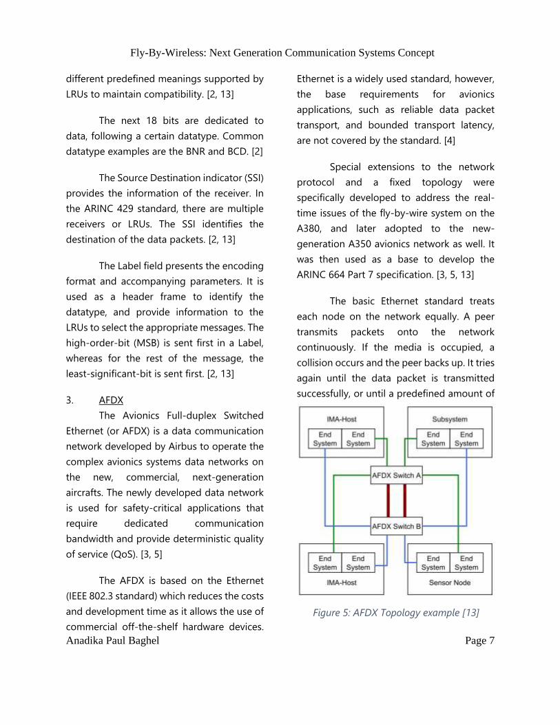
The word format of the data
transmitted using ARINC 429 consists of
various fields such as illustrated in Figure 4
and listed below as: [2]
Parity bit (1 bit)
Sign / Status Matrix or SSM (2 bits)
Sign or S (1 bit)
Data (18 bits)
Source / Destination Indicator or SDI
(2 bits)
Label (8 bits)
The parity bit for the ARINC 429
standard must be odd. The parity bit toggles
between 0 and 1 in order to ensure that the
total number of ones in the word is odd. [2,
13]
The SSM or Sign / Status Matrix
contains the information regarding hardware
status, data validity, or operation mode,
depending on the device type (defined by
the Label). SSM can be either in BCD (Binary-
Coded Decimal) or BNR (Binary Numbers)
datatype. Messages vary for the two
datatypes, for instance, 00 depicts Failure
Warning (FW) in BCD datatype and Verified
Data, Normal Operation in BNR datatype. [2,
13]
The single-bit Sign field depicts the
whether the number is positive or negative.
The binary bit 0 indicates Plus, North, East,
Right, To, Above. The binary bit 1 indicates
Minus, South, West, Left, From, Below. Other
bit patterns and data encoding variants have
Figure 4: ARINC 429 32 bit Word Format [4]
Fly-By-Wireless: Next Generation Communication Systems Concept 7
Anadika Paul Baghel Page 7
different predefined meanings supported by
LRUs to maintain compatibility. [2, 13]
The next 18 bits are dedicated to
data, following a certain datatype. Common
datatype examples are the BNR and BCD. [2]
The Source Destination indicator (SSI)
provides the information of the receiver. In
the ARINC 429 standard, there are multiple
receivers or LRUs. The SSI identifies the
destination of the data packets. [2, 13]
The Label field presents the encoding
format and accompanying parameters. It is
used as a header frame to identify the
datatype, and provide information to the
LRUs to select the appropriate messages. The
high-order-bit (MSB) is sent first in a Label,
whereas for the rest of the message, the
least-significant-bit is sent first. [2, 13]
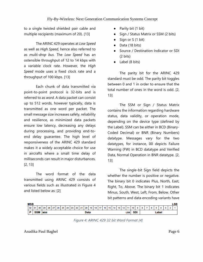
3. AFDX
The Avionics Full-duplex Switched
Ethernet (or AFDX) is a data communication
network developed by Airbus to operate the
complex avionics systems data networks on
the new, commercial, next-generation
aircrafts. The newly developed data network
is used for safety-critical applications that
require dedicated communication
bandwidth and provide deterministic quality
of service (QoS). [3, 5]
The AFDX is based on the Ethernet
(IEEE 802.3 standard) which reduces the costs
and development time as it allows the use of
commercial off-the-shelf hardware devices.
Ethernet is a widely used standard, however,
the base requirements for avionics
applications, such as reliable data packet
transport, and bounded transport latency,
are not covered by the standard. [4]
Special extensions to the network
protocol and a fixed topology were
specifically developed to address the real-
time issues of the fly-by-wire system on the
A380, and later adopted to the new-
generation A350 avionics network as well. It
was then used as a base to develop the
ARINC 664 Part 7 specification. [3, 5, 13]
The basic Ethernet standard treats
each node on the network equally. A peer
transmits packets onto the network
continuously. If the media is occupied, a
collision occurs and the peer backs up. It tries
again until the data packet is transmitted
successfully, or until a predefined amount of
Figure 5: AFDX Topology example [13]

Fly-By-Wireless: Next Generation Communication Systems Concept 8
Anadika Paul Baghel Page 8
time has elapsed, thus producing varying
latency lengths which is undesirable for
safety critical applications. This network
topology was changed in the AFDX. [5, 13]
In the AFDX, the data packets are
forwarded based on a connection table by
regular switches. The connection table is
build and updated while the switches are in
operation and it learns and forgets the peers
connected to the network, thus making it
convenient for networks with temporary
peers that can be attached and detached
from the net. However, the latency is still of
variable length. To tackle this issue, the AFDX
switch forwards packets according to a static
table as well, in which all the peers and their
respective network addresses are statically
defined. [3, 5, 13]
The network availability is increased
by developing redundancy on the physical
layer. Two Ethernet controllers transmit data
packets on separate wire using physically
separate switches. At the receiving end, two
individual controllers receive the data frame.
A redundancy management algorithm in the
protocol layer forwards at most one of the
two identical packets appropriately to upper
layers. [3, 5, 13]
The AFDX system architecture
consists of End Systems and switches. Any
system, such as a part of the avionics or an
aircraft subsystem, connected to the AFDX
network that is configured to handle AFDX
protocol operation is called an End System.
The switches are located between the End
Systems on the data path for
communication. The number of switches
depends on the network hierarchy. [3, 5, 13]
In order to implement the same
connection concept as ARINC 429, the point-
to-point and point-to-multipoint
connections are defined using Virtual Links
(VL), a unidirectional private line with
bounded latency and guaranteed bandwidth.
For a point-to-point topology, a single VL is
connects exactly two End Systems. For a
point-to-multipoint, a single VL can connect
one transmitting End System to multiple
receiving End Systems.
There are two main characteristics of
the VL - Bandwidth Allocation Gap (BAG) and
Maximal Frame Size (MFS). The BAG signifies
the minimum inter-arrival time between two
consecutive frames, ranging in powers of 2
from 1 to 128 milliseconds. The MSF
represents the largest frame that can be sent
during each BAG, ranging from 64 bytes to
1518 bytes. [3, 5, 13]
Figure 6: Virtual Link layout in the AFDX
network [13]

Fly-By-Wireless: Next Generation Communication Systems Concept 9
Anadika Paul Baghel Page 9
B. Advantages of Wired Aircraft
Communication System
In modern aircrafts, the
communications systems are of critical
importance as almost all the activities on
board, such as navigation, path guidance,
control surface movement, engine
monitoring, pressure maintenance, etc., are
heavily dependent on the communication
network in order to operate. The current
avionics network is a wired communication
system using the different data buses for
different tasks.
The main advantages of the current
avionics system installed in the aircrafts are
listed below: [7]
Data Rates of the System: The avionics
communications system transmit
data at the rate of 100 kbps for the
ARINC 429, 1 Mbps for the CAN Bus
and 100 Mbps for the AFDX system.
Hard Real Time and Determinism:
Data transmission latencies are
bound and function within the
deadline constraints, hence ensuring
a predictable manner of
communication and timeliness of
data guaranteed for determinism
concerns.
Reliability and Availability: The
avionics network communication
takes place over minimum three
layers of redundancy, hence has a
high criticality level and a probability
of failure of less than 10−9 per flight
hour. This is ensured by the
application of necessary fault
detection and recovery mechanisms.
The avionics network have an
expected lifetime of 20 to 30 years,
hence are mature enough to last a
long term.
Security: The current avionics network
guarantees data confidentiality,
integrity and authentication, by
providing a secure, guaranteed
communication lines with
mechanisms to prevent unauthorized
access to data.
Electromagnetic Compatibility: The
working conditions of the avionics
communication systems involves
harsh physical environments such as
vibration, variation in temperature
and humidity, pressure, as well as
constant presence of intense radio
frequency noise. The current avionics
network is capable to handle the
harsh environment with continuous
and periodic maintenance over time.

Fly-By-Wireless: Next Generation Communication Systems Concept 10
Anadika Paul Baghel Page 10
III. PROBLEM STATEMENT:
DISADVANTAGES OF THE WIRED
COMMUNICATIONS SYSTEMS
In this section, the main
shortcomings of the current wired avionics
systems are discussed. The disadvantages are
weighed against the possibility of a better
solution for the next-generation aircrafts.
As the years pass by, the ramification
of the communication systems on board the
aircrafts becomes increasingly intricate. The
load on the network is increased due to the
rising demands of data for development,
research, maintenance and monitoring
purposes. The end result of the inflammation
of complexity of avionics communications
systems is an upsurge in electrical wires, as
all the systems and subsystems depend upon
cables and connectors to provide data,
power, grounding and time-synchronization
throughout the aircraft’s lifetime.
Many improvements and
developments have been made to the
current avionics systems, but their heavy
dependencies on wires has never eliminated
the wiring and connector problems, and
therefore being the key reasons for flight
delays and increase in maintenance costs.
New systems also lead to increase in weight
not only in the form of cables, but also
insulation, bulkheads, brackets, connectors,
cable trays, structural attachment and
reinforcements. [7]
For a better understanding, cable
related costs during fabrication and
installation are estimated to about $2000 per
kilogram of wire. In an average commercial
aircraft, the total wire count adds up to
approximately 100,000 cables with an
approximate total length of 450 to 470
kilometers. The weight of the cables alone
ranges from 5000 to 5,700 kilograms, and
additional 30% weight for the harnesses. The
overall weight sums up to almost 2 – 5% of
an aircraft’s weight. Financially, it costs
around $14 million for an A320 and
Figure 7: An insider's look into the avionics
bay of the B777 [20]
Figure 8: Wire chaffing due to vibrations [19]

Fly-By-Wireless: Next Generation Communication Systems Concept 11
Anadika Paul Baghel Page 11
approximately $50 million for a B787. The
Airbus 380, largest commercial aircraft to
date, consists around 500 km of cables which
are one of the main reasons for production
delays and cost overruns, costing up to an
estimate of $2 billion. For perspective, the
operating empty weight of an A380 is
roughly 277,000 kg. Considering the wiring
to weigh 2.5%, the cables and harnesses
together weigh almost 7 tons. [7]
Another major downside to the
wiring systems, apart from increase in
weight, is the problems that arise due to wire
aging. As an aircraft ages, the electrical
system also ages and the insulation becomes
brittle and cracks over the kilometers of
cables laid out in the aircraft structure. The
vibrations cause the insulation to chafe as
wires rub against each other, a tie-down or
any other surfaces. Insulation can also
breakdown in the presence of moisture,
generally spawned due to the varying
humidity levels during flight. Chaffing can
lead to exposed wires causing arcs, shorts
and electromagnetic emission and
interference. [7]
Unlike the distinctly visible cracks on
the airframe or engine parts, damaged wire
is extremely difficult to detect as the wires are
tied down to the aircraft frame, twisted
around fuel tanks and hydraulic lines, making
it extremely difficult to reach for
maintenance. In many situations,
maintenance of electrical wires requires
dismantling of external aircraft structures,
which requires longer periods of time, and
hence increases overall maintenance costs.
[16]
According to a recent study
conducted by a research firm,
Lectromechanical Design Co., based in
Virginia, USA, more than 3000 cracks were
found over approximately 240km of wires in
a Lockheed L-10 11 that was in service for
several years. Each crack can be a potential
cause for catastrophic arcing that may lead
to electrical fires in an aircraft. [16]
Unfortunately, there have been a few
incidents caused due to bad wiring and
electrical failures. For example, in 1989,
United 811 met with a fatal accident due to
improper wiring which indicated the aircraft
door was locked, when in fact it was
unlocked, causing the door section to
breakdown during flight. Another mishap
occurred in 1996, when flight TWA 800
(Figure 9) exploded mid-air due to a short
circuit near the central wing fuel tank. One
Figure 9: Wire aging in aircrafts [18]
Fly-By-Wireless: Next Generation Communication Systems Concept 12
Anadika Paul Baghel Page 12
more disaster occurred with Swissair 111 in
1998, where an electrical fire caused due to
arcing in the IFE system led to fatal demise of
all 299 persons on board. [8, 9, 10, 16]
To summarize the problem statement
addressed in this paper, the main
disadvantages of the current wired
communications systems are listed below:
[17]
Performance: The increase in weight
due to wires directly impacts fuel
consumption and aircraft flight
performance. In order to maintain
reliability, the communication
systems are made redundant with
minimum three layers of wiring
systems. This heavily increases the
overall weight of the electrical system
which is a bane for aircraft
performance efficiency.
Failure of wires and connectors: Most
of the troubleshooting and
maintenance overruns are caused by
issues related to cables and
connector failures.
Direct Costs: Wiring system
measurement justification, design
and implementation, structural
provisions, inspections, tests,
logistics, vendor availabilities, etc.
mount to a huge cost for airliners and
aircraft manufacturers.
Price of Copper: The increase in price
of copper over the last decade has
heavily impacted the electrical wires
industry.
Electromagnetic Interference: Wiring
constitutes to more than 50% of the
cases of electromagnetic interference
on board the aircraft by radiating
high amounts of energy. The cables
behave as antennas, collecting
unwanted energy that can impact the
immunity of interconnected systems.
Cost of change/inflexibility: Since the
introduction of composite structure
materials, health monitoring systems
have become an essential addition to
the system. However, sensors are
limited due to wiring weight
restrictions. Also, the system
architecture is not flexible enough
and requires huge costs to allow easy
attachment / detachment of new End
Systems to the network.
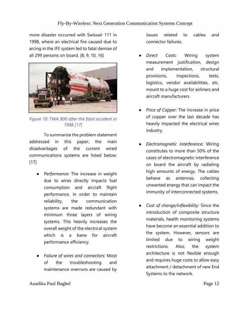
Figure 10: TWA 800 after the fatal accident in
1998 [17]

Fly-By-Wireless: Next Generation Communication Systems Concept 13
Anadika Paul Baghel Page 13
IV. PROPOSED SOLUTION: WIRELESS
COMMUNICATIONS SYSTEMS
The proposed solution for the current
wired avionics communications system is
discussed in this section. The wireless system
is detailed and network implementation is
explained as a possibility for future aircraft
communication systems.
The complications that arise with
complexity of avionics networks can be
reduced by eliminating physical connections,
i.e. replacing wires and cables with a wireless
communication line between the systems.
The ‘Fly-By-Wireless’ paradigm has the
potential to improve efficiency and flexibility,
while reducing weight, fuel consumption and
maintenance costs. The steep development
in technology has allowed the
communications to take place wirelessly in a
cost effective manner due to their simplicity,
maturity and ubiquity. A good example of
real time wireless application is wireless
sensors network and wireless industrial
networks. [7]
Some of the major advantages of
substituting a wired system with wireless
communication are listed below: [15]
Weight Reduction: The main reason to
replace the existing wired system is
the bulky nature of hardware
connections that increase the
system’s weight.
Cost effective: Wireless systems offer
solutions that efficaciously reduce the
cost and time related with wiring
harness design, harness installation
design, aircraft manufacturing time,
and aircraft lifecycles costs.
Maintenance costs are also drastically
decreased due to the presence of less
wires.
Redundancy: In the aircraft, wireless
communication paths can be made
redundant more easily and with
higher cost efficiency through the use
of mesh networks, which could not be
implemented in a hardwired system
due to weight and cost limitations.
Back Up: The wireless communication
system can also be implemented as a
backup for the main wired avionics
network to increase reliability and
safety in case of failure.
Additional Features: Wireless
technologies can provide new
functionalities to aircraft
manufacturers and operators that
could not be provided by wired
systems due to various limitations.
Additional functions such as
affordable health monitoring
systems, easy addition of new sensors
including engine rotor bearing
monitoring, wireless transmission of
sensor information, wireless crew

Fly-By-Wireless: Next Generation Communication Systems Concept 14
Anadika Paul Baghel Page 14
communication including voice,
video and data to provide enhanced
aircraft safety.
In the following sections, the Fly-By-Wireless
implementation methods are discussed in
detail. Section (A) accounts the possible
wireless solutions using commercial off-the-
shelf technology, and section (B) discusses
the possible system architecture using
wireless technology.
A. Commercial Off-The-Shelf (COTS)
Technology
The avionics communication system
is quite a complex network of End Systems
transmitting and receiving time-critical data.
In order to reduce development costs, pre-
existing devices and solutions, called
commercial off0the-shelf technology (or
COTS), can be adapted for the avionics
network applications. Selecting an
appropriate wireless technology with the
required specifications that are equal to or
better than the current wired avionic
network.
Three of the most appropriate
wireless technologies for avionics systems
have been explored, and the most
appropriate standard selected to be
implemented. [7]
1. 802.11n
The Institute of Electrical and
Electronics Engineers or IEEE develops
communication standards and specifications
for various applications. The IEEE 802.11 is
one of the most widely used communication
standard. The proposed option for
application in avionics is a variation of the
basic, namely 802.11n. [7, 11]
The 802.11n is an amendment that
improves upon the previous standards by
having the additional facility of multiple-
input multiple-output antennas (MIMO). It
has a data rate of 600 Mbps, six times faster
than the current AFDX standard, and hence
can be used as the avionics backbone
network. [7]
The variant operates at 2.4GHz and
5GHz with two bandwidths of 20MHz or
40MHz. One drawback is the general
purpose frequency of 2.4GHz which is the
same for commonly used Wi-Fi, hence
creating security concerns. However, the
standard has a good maximum range of 30
metres and provides 3 non-overlapping
COTS Wireless Technology
802.11n ECMA-368 802.15.3c
Figure 11: Three COTS wireless technologies
studied

Fly-By-Wireless: Next Generation Communication Systems Concept 15
Anadika Paul Baghel Page 15
channels that can be used for different End
System communications. [7]
MAC protocol applied in the 802.11n
standard is based on CSMA/CA mechanism.
For ad-hoc mode it gets integrated with
Distributed Coordination Function or DCF
protocol. For infrastructure mode, it
integrates with contention free Point
Coordination Function or PCF protocol. The
802.11n uses Automatic Retransmission
ReQuest (ARQ), at the MAC layer, with
different acknowledgement status messages
such as immediate-ACK, delay-ACK and
block-ACK. At the PHY layer, the Forward
Error Code (FEC) and Low-Density Parity-
Check (LDPC) are implemented to control
errors and improve reliability. [7]
For increased security, IEEE 802.11n
standard adopts weak RC4 stream cipher as
well as Advanced Encryption Standard (AEC)
algorithm to ensure security against brute
force attack. [7, 11]
2. ECMA-368
Developed by the European
Computer Manufacturers Association, the
ECMA-368 is a High Rate Ultra-Wideband
(HR-UWB) PHY and MAC Standard for a
high-speed, short-range wireless network,
utilizing all or part of the large spectrum
bandwidth ranging between 3.1GHz to
10.6GHz. The large frequency band is divided
into 14 non-overlapping channels, out of
which channels 9, 10 and 11 are not in use for
any application and available all over the
world, hence making it quite appropriate as
it can be reserved specifically for avionics
applications. [12]
The data rate supported by the
ECMA-368 is 110Mbps for a range of 10
metres, 200Mbps for 6 metres range, and
480Mbps for a small distance of 2 metres.
The data rate is faster when compared to the
100Mbps of the AFDX standard. [12]
There are two MAC protocols
supported by the ECMA-368. The Prioritized
Contention Access (PCA) is a contention
based protocol with prioritized Quality of
Service. The other protocol is the Distributed
Reservation Protocol (DRP) which is TDMA
based and guarantees a contention-free
access. [7, 12]
The ECMA-368 ensures reliability by
supporting FEC convolutional code with
different coding rates at PHY layer and re-
transmission mechanisms with Immediate
Acknowledgement (Imm-ACK) and Block
Acknowledgement (B-ACK) at MAC layer. [7]
It supports peer-to-peer topology
and uses AES algorithm with Pairwise
Transient Key (PTK) for unicast
communications, and Group Transient Key
(GTK) for multicast and broadcast
communications. [7, 12]

Fly-By-Wireless: Next Generation Communication Systems Concept 16
Anadika Paul Baghel Page 16
3. 802.15.3c
The IEEE 802.15.3c is a very recent
development and is of interest for the
avionics application purely because of its
high speed data rate of 3000Mbps. It
operates on 60GHz frequency with a 7GHz
bandwidth with a single non-overlapping
channel. [7]
The main drawback of this IEEE
variant is the severe attenuation caused due
to oxygen absorption. Hence, the 60GHz is
based on directional antennas with Line-of-
Sight (LoS) communication to reach the high
speed of 3GHz. [7]
B. Proposed System Architecture
The wireless avionics network must
be designed to be able to support 60-80
nodes or End Systems, have a data rate equal
to or higher than 100Mbps, provide end-to-
end delay and reliability guarantee, support
peer-to-peer topology for secure
communications, and also be able to handle
the physical harsh environments that occur
during aircraft flight. The commercially
available off-the-shelf technologies reduce
development costs but have their own
limitations as they are not designed for the
specific application of avionics
communications.
Keeping the requirements of the
current avionics system and the limitations of
the COTS wireless technologies in mind, a
Hybrid Architecture is suggested for the
Wireless Avionics Network, i.e. the system
consists of wired and wireless technology. [7]
From the three wireless technologies
discussed above, the most suitable for the
avionics application is the ECMA-368 as it
satisfies the desired data rate, supports peer-
to-peer topology, and provides high level of
data encryption and reliability, hence
ensuring data security and guarantee.
Moreover, the ECMA-368 has 3 channels
available that are not being used. These
channels can be reserved for avionics
application, increasing the data security as
no other application will be valid at the same
frequency. [7]
The hybrid architecture is designed
keeping 1Gbps Full Duplex Switched
Ethernet as the base and interconnected to
three clusters on the three channels (9, 10
and 11) via gateways. The gigaswitch is
connected with the three gateways using a
wired Full Duplex connection. The gateways
are connected with the various End Systems
via the wireless ECMA-368 standard. In order
Figure 12: Proposed hybrid architecture as
possible solution

Fly-By-Wireless: Next Generation Communication Systems Concept 17
Anadika Paul Baghel Page 17
to increase reliability, the multicast network
supports positive and negative
acknowledgment between the peers. [7]
The system ensures data reliability
and security, as well as feasibility with this
hybrid design. Overall weight of the
communications systems also reduces as a
major chunk of cabling is eliminated by the
implementation of wireless technology for
data packet transmission and reception by
End Systems.
V. ASSESSMENT OF WIRELESS
TECHNOLOGIES
In this section, the application of the
hybrid architecture and the possible need for
development of new wireless technology for
the avionics network application is discussed.
The next generation aircrafts are
being designed to enhance the functionality,
reliability and efficiency of the system, but at
the same time maintain or increase the
system security. In order to reduce the overall
aircraft weight and improve the
performance, inclusion of wireless
technologies for communication systems is
suggested. However, due to the lack of
desired specification in the current
commercial off-the-shelf wireless
technology, the proposed design is a hybrid
architecture consisting of both wired and
wireless communication systems.
The future of aviation, nevertheless, is
rapidly heading towards wireless technology.
In order to implement a 100% wireless
avionics communications network while
maintaining the current standards for data
security, reliability and data rate, new
wireless technology must be developed
specifically to satisfy the requirements of
avionics systems applications.
The avionics systems have a complex
network and safety-critical applications, and
hence require a dedicated wireless
specification. The Wireless Avionics Intra-
Communications project is conducted by the
Aerospace Vehicles Systems Institute (AVSI),
a group of companies that, together with
NASA, FAA and ICAO, are working towards
developing new avionics centered wireless
technology. Their aim is to “provide
communications over short distances
between aircraft stations installed on a single
aircraft” and believe approximately 30% of
Figure 13: Group of leading aircraft
manufacturing companies working on WAIC
project [16]

Fly-By-Wireless: Next Generation Communication Systems Concept 18
Anadika Paul Baghel Page 18
electrical wires are viable candidates to be
substituted with wireless technology. [15]
To begin with, the objective of the
organization is to develop wireless systems
for safety and flight regularity applications
that require low transmission power (up to
10dBm) such as provide data from sensors
wirelessly. Other applications can include
data for ice detection, cabin pressure, engine
sensors, landing gear position, door sensors,
and many more. [15]
The AVSI group was successfully
allocated a worldwide radio frequency
spectrum for wireless avionics at the 2015
World Radiocommunication Conference
(WRC-15). This is a major step towards the
development of wireless avionics technology
as it enables a globally applicable licensing
process, as well as provides harmonization of
the technical and operational conditions
across regions and countries. The frequency
allocation also allows the systems to be
designed universally and with ease within the
aeronautical frequency bands. [15]
The wireless technology is a feasible
solution with the help and development of
projects such as the Wireless Avionics Intra-
Communication project, as it allows the
engineers, designers and manufacturers to
explore and enhance advanced
communications systems, in addition to
increase the capability of aircraft
communication systems.
VI. CONCLUSION
The future of avionics
communications systems and networks has
been discussed in this paper. The history of
aircraft communication system is introduced,
as well as a detailed description of the
current wired avionics network, including the
three main communication buses used in
aircrafts, namely the CAN bus, ARINC 429
bus and the AFDX system.
The problem statement has been
defined as the main disadvantages of the
wired communication systems, such as
increased weight, high installation and
maintenance cost, wire aging liabilities, as
well as fatal aircraft accidents caused due to
electrical failures.
Use of wireless technology for
avionics communications has been proposed
as a possible solution to overcome the
challenges faced by wired systems. The
benefits of wireless technology has been
discussed, along with possible COTS wireless
standards that can be viable candidates in
aircraft communications systems. The ECMA-
368 standard was recommended and a
hybrid architecture using the wireless
standard and a wired Full Duplex Ethernet
system has been suggested to better
understand the methods of implementation
for avionics application.
Lastly, the outlook of a completely
wireless communication avionics system is

Fly-By-Wireless: Next Generation Communication Systems Concept 19
Anadika Paul Baghel Page 19
discussed by suggesting developing new
wireless technology specifically for avionics
systems. Work done by the AVIS on the
Wireless Avionics Intra-Communications
(WAIC) project is mentioned, detailing the
project aim of 100% wireless
communications in aircraft, in addition to the
impacts of frequency allocation to the
project for avionics applications.
VII. REFERENCES
[1]R. ARINCDirect, "Rockwell Collins' |
ARINCDirect | Home", Rockwell Collins’
ARINCDirect, 2017. [Online]. Available:
http://www.arincdirect.com/. [Accessed:
06- Jul- 2017].
[2]"ARINC 429 Data Bus
Characteristics", Dropletmeasurement.co
m, 2017. [Online]. Available:
http://www.dropletmeasurement.com/P
ADS_Help/ARINC_429_Data_Bus_Charac
teristics.htm. [Accessed: 06- Jul- 2017].
[3]B. Pasquier and S. Schneele, Avionics Full
Duplex Ethernet and the Time Sensitive
Networking Standard. Pittsburgh, PA,
USA: IEEE, 2017, pp. 7-22.
[4]"Avionics Full-Duplex Switched
Ethernet", En.wikipedia.org, 2017.
[Online]. Available:
https://en.wikipedia.org/wiki/Avionics_F
ull-Duplex_Switched_Ethernet.
[Accessed: 06- Jul- 2017].
[5]D. Schaadt, AFDX/ARINC 664 Concept,
Design, Implementation and Beyond.
Whitepaper, 2017, pp. 3-5.
[6]2017. [Online]. Available:
https://www.researchgate.net/publicati
on/261269790_Fly-By-
Wireless_for_next_generation_aircraft_C
hallenges_and_potential_solutions.
[Accessed: 06- Jul- 2017].
[7]D. Dinh-Khanh, A. Mifdaoui and T.
Gayraud, "Fly-By-Wireless for next
generation aircraft: Challenges and
potential solutions", 2012 IFIP Wireless
Days, 2012.
[8]"Flight 811: the untold story", Stuff, 2017.
[Online]. Available:
http://www.stuff.co.nz/sunday-star-
times/features/1400976/Flight-811-the-
untold-story. [Accessed: 06- Jul- 2017].
[9]2017. [Online]. Available:
https://www.bu.edu/bostonia/winter-
spring14/what-really-happened-to-
twa-flight-800/. [Accessed: 06- Jul-
2017].
[10]"Swissair Flight 111", En.wikipedia.org,
2017. [Online]. Available:
https://en.wikipedia.org/wiki/Swissair_Fl
ight_111. [Accessed: 06- Jul- 2017].
[11]"What is 802.11n? - Definition from
WhatIs.com", SearchMobileComputing,
2017. [Online]. Available:
http://searchmobilecomputing.techtarg

Fly-By-Wireless: Next Generation Communication Systems Concept 20
Anadika Paul Baghel Page 20
et.com/definition/80211n. [Accessed:
06- Jul- 2017].
[12]Standard ECMA-368, 3rd ed. 2017, p. 5.
[13]C. M. Fuchs, "The Evolution of Avionics
Networks From ARINC 429 to
AFDX", Seminar Aerospace Networks
SS2012, pp. 65-67, 70-72, 2012.
[14]R. Knueppel, "Standardization of CAN
networks for airborne use through
ARINC 825", CAN in Automation, pp. 7-
9, 2012.
[15]A. WAIC and R. Information, "About
WAIC", Waic.avsi.aero, 2017. [Online].
Available: http://waic.avsi.aero/about/.
[Accessed: 06- Jul- 2017].
[16]J. Kumagai, "Down to the Wire", IEEE
Spectrum, pp. 34-39, 2001.
[17]G. Studor, "Fly-By-Wireless" : A
Revolution in Aerospace Vehicle
Architecture for Instrumentation and
Control. NASA/JSC, 2013, pp. 1-2.
[18]P. Carvalhal, M. Ferreira, L. Silva and J.
Afonso, "Design and Development of a
Fly-by-Wireless UAV
Platform", University of Minho, Portugal,
2009.
[16]Group of leading aircraft manufacturing
companies working on WAIC project. .
[17]CNN, TWA 800 after the fatal accident in
1998. .
[18]IASA, Wire aging in aircrafts. .
[19]IASA, Wire chaffing due to vibrations. .
[20]Australian Airlines, An insider's look into
the avionics bay of the B777