Embed Size (px)
Citation preview

BSA 04-11. 1/ 18f2016 Procedure: HDP-PR-FSS-701. Final Status Survev Plan Develooment
- · -Hematite
Decommissioning Revision: Appendix P-3 Project 10 Page I of7
.., . ···- .. -............ ····--· ·····-·· .... ·- . -. ·-· -.. --
APPENDrx P-3 FSS SAMPLING PLAN
Survey Area: BSA 04 Survey Unit: ll
Description:
Description:
Building Survey Area (Miscellaneous Other Structures) Structural Materials (concrete side\\alks, peripheral asphalt, transformer unit and pad) in LSA 08-16
Overview: The Survey Unit (SU) identified as Building Survey Area (BSA) 04-11 has been prepared for Final Status Survey (FSS) by the Hematite Decommissioning Project (HDP). This appendix provides an overview of the proposed FSS implementation as well as general and specific instructions for the technicians responsible for performing the FSS.
• Data Quality Objectives
1. Personnel pcrfonning FSS duties meet the qualifications listed in HOP-PR-HP-I 02 Health Physics Technician Trai11i11g and have received training and instruction commensurate with their duties. The RSO ha~ approved all FSS personnel to perform work associated \~ ith their individual roles and responsibilities. Training record~ are documented in accordance with I IDP-PR-GM-020, Training Material Development and Docu111e111ation of Training.
2. All HOP F'SS procedures ("700 series'') have been reviewed, revised, and validated in order to ensure performance of actual FSS work activities reflect the requirements detailed in the individual FSS Procedures and the HDP Decommissioning Plan.
3. All FSS instrumentation has undergone a receipt inspection by HOP QA personnel, is within current calibration. and is determined to be functioning within acceptable ranges based on initial set-up and daily source checks in accordance with HDP-PR-llP-411, Radiological Instrumentation. HP technicians v.ill confirm that environmental conditions (e.g. operating temperature range, no wet surfaces) arc acceptable for use of field instrumentation.
• Location
BSA 04-1 I is designated Class 1 and comprbcs the structural materials such as a concrete pad, sidewalks, peripheral asphalt, and a transformer unit located within the Land Survey Arca (LSA) 08-16. BSA 04-1 I and LSA 08-16 are located within the ··central Open Land Area'' as described in Table 14-16 of the HOP Decommissioning Plan (DP). BSA 04-11 and LSA 08-16 are also located in Area 4, an internal designation used for HOP task planning purposes. The total surface area of BSA 04-11 is 102 m2
•
• Background
This BSA survey unit was not specifically described in
t -'¢ N
.~~wli·:":.fi[§Ql ~~ HOP Satellite Site View: BSA 04-t l in crosshatch,
LSA 08-t6 in Red Outline
the DP. Since the underlying land (LSA 08- 16) is a Class 1 SU, the structural materials comprising BSA 04-11 have also been designated a Class I SU. Based on its historic use as a subsurface utility service corridor and as a travel path for equipment and personnel traffic, BSA 04-11 is designated Class I \\ hich align~ wilh the Class I designation of the underlying LSA 08-16. Hov.ever, based on the final RASS and ongoing routine surveillance, there is little potential for residual radioactivity to
Quality Record

BSA 04-11 , 1/ 18/2016 Procedure: HDP-PR-FSS-70 I, Final Status Survey Plan Development
Hematite Decommissioning Revision: Appendix P-3
Project 10 Page 2of7
represent more than a small fraction of the Structures, Systems, and Components (SSC) DCGL of 18,925 dpm/100 cm2
.
BSA 04-11 underwent final remedial action support surveys (RASS) during late November, 2015, including a I 00% scan of exposed surfaces and 11 systematic total surface contamination (TSC) measurements. Swipe samples were collected at each TSC measurement location.
All direct measurement activities were well below the applicable SSC DCGL (with a maximum measurement at 3.0% of the DCGL) and removable activity was less than I 0% of the measured total activity results at all locations. These data suppo1t the current Class I designation for BSA 04-11.
Since BSA 04- 1 I is a Class I SU, typical Isolation and Control (I & C) postings (green/white rope with signage) will be required to be installed before FSS begins. Although this SU is a frequently utilized area of the HOP, ongoing routine surveillance will serve to confirm that no crosscontamination is occun·ing within the SU after completion of FSS activities.
• Criteria
All FSS analytical results for measurements/samples collected within BSA 04- I I (except for the transformer unit) will be evaluated against the HOP SSC Gross Activity DCGL of 18,925 dpm I I 00 cm2
• Any scans or measurements collected during the FSS which exceed the DCGL will require fu1ther evaluation by the FSS Supervisor and RSO for a potential elevated measurement investigation.
Radionuclide Structural Surfaces ( dpm I 100 cm2)
Total Gross Activity 18,925
.. Table adapted from HDP FSS Procedure HDP-PR-FSS-70 I, Fmal S1at11s Survey Plan Developmem, Rev1s1011 I 0, November 2015.
• Implementation
As a Class l SU, BSA 04-11 wil l undergo a I 00% scan of all exposed structural surfaces (including the transformer unit) using a combination of a Ludlum 43-37 gas-proporti'onal floor monitor and handheld Ludlum 43-93 alpha-beta dual channel scinti llation detectors.
Perform static biased measurements at points on the concrete pad, sidewalks, and asphalt pavement such as cracks, seams, holes, or depressions where the Scan MDC was exceeded. Consult FSS supervision for gu idance on the amount and specific locations of biased measurements. At locations where static measurements exceed the survey instrument static M DA, adjustments to instrument efficiency or volumetric sampling ~ay be necessary - consult FSS supervision for guidance.
Based on a statistical evaluation of the RASS dataset, a minimum of eleven ( 11) measurement locations were calculated for BSA 04~ 11 and 12 locations were designed. As the BSA is a Class 1 survey unit, all measurement locations were designed on a systematic triangular grid based on a random starting point. Direct (TSC) measurement locations are given in standard Missouri East NAO 1983 Northing/Easting coordinates.
ARer each static measurement, within the same area as the static measurement. cloth smears will be swiped with moderate pressure over an area of l 00 cm2 (a 4" by 4" square) in an S-shaped pattern in
Quality Record

BSA 04-11 , 1/1 8/2016 Procedure: HDP-PR-FSS-701 , Final Status Survey Plan Development
Hematite Decommissioning Revision: Appendix P-3
Project 10 Page3of7
order to assess removable activity.
Al I survey measurements and swipes collected on the transformer unit itself will be evaluated against the radioactivity limits given in the table below.
Radionuclide Transformer Unit Surfaces* (dpm/100 cm2)
Total Alpha Activity 5,000 (U-naL U-235. U-238. and associated decay products)
Total Beta Activity 5,000 (U-nat. U-235. U-238. and associated decay products)
Removable Alpha Activity 1,000 (U-nai. U-235. U-238. and associated decay products)
Removable Beta Activity 1,000 (U-nai. U-235. U-238. and associated decay products)
... Table adapted from Table lof ··Guidelines for Decontammat1on of Fac1h t1es and Equipment Pnor to Release for Unrestricted Use or Termination of Licenses for Byproduct. Source. or Special Nuclear Material .. , April 1993.
Since no systematic measurement from the general area grid design for BSA 04- 11 fel I on the transformer unit, a minimum of 11 judgmentally determined static measurements and swipes will be collected at various points on the exposed surfaces of the transformer.
Per HDP-PR-FSS-703, QC replicate survey requirements for structural survey units require that 5% of all Class 1, Class 2, and Class 3 SSC Survey Un its are randomly selected to undergo a replicate survey of the entire SU area. The replicate survey is to be performed by an HP technician other than the one who performed the initial survey using similar instrumentation. BSA 04-11 is not one of the randomly selected SU for which a replicate survey has been required.
Quality Record
BSA 04-11. l/18/2016 Procedure: HDP-PR-FSS-70 I, Final Status Survev Plan Development
Hematite Decommissioning Revision: Appendix P-3
Project 10 Page 4of7
FSS IMPLEMENTATION SUMMARY TABLE
Portable Instrument Scanning: Scan Coverage I 00% of BSA 04-11 total exposed area
Scan MDC 1, I 48 dpm I I 00 cm«Ludlum 43-3 7) 2, 187 dpm I I 00 cm2 (Ludlum 43-93)
Investigation Action Level (lAL): general area 9,463 dpm I 100 cm4 (50% of the DCGL) IAL: (cracks, holes, seams) 2, I 87 dpm I l 00 cm2 (Ludlum 43-93)
Total Surface Contamination (TSC) Measurements: Surface Minimum Number of Comments
Measurements A total of 12 TSC measurements
locations have been systematically Structural Materials (concrete designed from a random starting
pad, sidewalks, asphalt, 11
point. A minimum of l I transfonner) overlying judgmentally determined static
LSA 08-16 measurements and swipes will be collected at various points on the
exposed surfaces of the transformer
TSC Investigation Action Level I 8,925 dpm I I 00cm2 (Adjusted Gross DCGL)
(not applicable to transformer)
Removable Activity Locations:
After each TSC measurement, at the same point as the TSC measurement, using moderate pressure swipe a cloth smear over the surface (e.g. exterior wall, roof, window, etc.) in ru1 S-shaped pattern within an approximately 4" by 4" box.
Biased Measurement Locations: Perfonn static biased measurements at points on the concrete and asphalt surfaces such as cracks, holes, or seams where the Scan MDC was exceeded. Consult FSS supervision for guidance on the amount and specific locations of biased measurements. At locations where biased measurements exceed the instrument static MDA, adjustments to instrument efficiency or volumetric sampling may be necessary - consult FSS supervision for guidance.
Instrumentation Ludlum 2360 with 43-37 floor monitor Used for general area scanning of the floor
Ludlum 2360 with 43-93 scintillation Used for wall, ceiling, roof scanning and detector; to obtain static (TSC) measurements.
Ludlum 2929 with 43-10-1 scintillation detector Used for counting of swipe (smear) samples.
Quality Record

BSA 04-11, 1/18/2016 Procedure: HDP-PR-FSS-70 I, Final Status Survev Plan Develooment
Hematite I
Decommissioning Revision: Appendix P-3 Project 10 Page 5of7
-
General Instructions: 1. Summarize daily work activities on the log sheets provided in Appendix P-6 (from procedure HDP-PR
FSS-70 I, Final Status Survey Plan Development). Provide a description of work area conditions, measurements collected (including swipes for removable activity) and the status of instrument scan surveys for every shift that involves work in this survey unit. Document the surveyor name and instrumentation used for each structural surface survey on Appendix A- I (from procedure HDP-PR-FSS-712, Final Status Surveys of Structures. Systems, and Components) and on Appendix P-6 for reporting traceability. In the event that a situation arises where the survey instructions cannot be followed as written, stop work and contact the FSS Supervisor for resolution. All changes to the survey instructions shall be approved by the RSO before continuing work and be documented in the FSS Field Log.
2. [n accordance with HDP-PR-FSS-70 I, (Sec. 8.4.2), documentation of activities performed, equipment used, and potential safety hazards that may be encountered during the performance of characterization activities (along with associated controls) will be documented using the FSS Daily Task Briefing log sheet.
3. Since BSA 04-11 is a Class 1 SU and a frequently utilized area of the HOP, typical isolation controls (I & C) are required, but likely will not be installed until the pad area is no longer needed for HOP task support. Ongoing routine surveillance will serve to confirm that no cross-contamination has occurred within the SU after completion of FSS activities.
4. ln accordance with HDP-PR-HP-411 , Radiological Instrumentation, confirm that FSS instrumentation is within the current calibration period, has been daily source checked, and environmental conditions are acceptable for field use as per the manufacturer's recommended operating parameters. As required by HDP-PR-HP-415, Operation of the Ludlum 2360 for Final Status Survey, calculation of weighted efficiencies for each survey detector used during FSS of BSA 04-11 will be performed prior to field use.
5. Structural FSS are to be performed in accordance with HDP-PR-FSS-712, Final Status Surveys of Structures, Systems, and Components, using instrumentation that has been documented and prepared per the requirements of HDP-PR-HP-411 and HDP-PR-HP-415. BSA 04-11 is a Class I Survey Unit. A total of 12 systematically distributed TSC measurements will be taken across the entire survey unit. One hundred (100%) of the exposed survey unit area, including the transformer unit, will be scanned by a combination of a floor monitor (Ludlum 43-37) and handheld survey probes (Ludlum 43-93).
6. The majority of the scanning survey of the concrete sidewalks and peripheral asphalt will be performed using a Ludlum 43-37 gas proportional floor monitor. Move the floor monitor systematically across the surface at a speed between I and 2 inches per second. Ensure the probe set screws maintain a close, even distance (nominally W', but not to exceed Yi") to the floor surface. Localized investigational scanning of surface features with greater potential for residual radioactivity (such as cracks, holes, depressions) should be performed using a Ludlum 43-93 alpha-beta scintillation detector. Move the handheld survey probe systematically across all surfaces at a speed between I and 2 inches per second while holding the probe as close (nominally W', but not to exceed Yi") to the surface as conditions allow. The scanning surveys will cover the percentage (I 00%) of the accessible surface areas within the area of interest as indicated in the table above. Notify the FSS Supervisor of any areas, conditions or constraints where surveying (or subsequent TSC) may not be possible. Document the conditions and any resolutions in the FSS Field Log.
7. Perform static biased measurements on concrete and asphalt features such as cracks, holes, and seams where the Scan MDC was exceeded. Consult FSS supervision for guidance on the amount and specific locations of biased measurements. At locations where biased measurements exceed the static MDA, adjustments to instrument efficiency or volumetric sampling may be necessary - consult FSS supervision
Quality Record

BSA 04-11, 1/18/2016 Procedure: HDP-PR-FSS-70 I, Final Status Survey Plan Development
Hematite Decommissioning Revision: Appendix P-3
Project 10 Page 6of7
for guidance.
8. Static TSC measurements made with the scaler-ratemeter (Ludlum 2360) coupled to the handheld detector will be manually recorded onto a field survey diagram. Results of the structural survey wi II be documented on form Appendix A-1 from HDP-PR-FSS-712. A minimum of 11 judgmentally determined static measurements will be collected at various points on the exposed surfaces of the transformer.
9. A map or diagram of the structural survey area will be attached to the survey instruction. Direct measurement locations are given in standard Missouri East NAD 1983 Northing/Easting coordinates.
10. Swipe samples will be collected at each TSC measurement location after the static count is completed. A minimum of 11 judgmentally determined swipe samples will be collected on exposed transformer surfaces after the corresponding static measurements have been made. All swipe samples will be analyzed in the onsite FSS office using the Ludlum 2929 swipe counters for gross alpha/gross beta activity.
11. No volumetric sampling is anticipated as prut of the FSS effort for BSA 04-11 (see also General Instructions #7).
Specific Instructions: NOTE: Unless otherwise indicated, the performance of these specific instructions is the responsibility of the HP Technician.
Before Beginning Work
1. Rad. Engineer/HP Technician: Perform a daily task-specific briefing; documenting the planned work activities, anticipated hazards, and controls on the FSS Daily Task Briefing log sheet. The primary hazard anticipated during FSS of BSA 04-11 is slips, trips, and falls due to uneven walking surfaces.
2. Rad. Engineer/HP Technician: Verify that survey instrumentation is within the current calibration period by checking the calibration due date for each piece of instrumentation used for FSS. Perform daily preand post-survey daily source checks for handheld survey instrumentation in accordance with HDP-PR-HP-411. Confirm that environmental conditions in which the survey will be perfom1ed are within the manufacturer's recommended operating range (e.g. temperature between -4° F to 122° F).
3. Rad Engineer/HP Technician: Prior to survey, collect three background measurements in (alpha+ beta) scaler mode at waist level per Step 8.4.1 of HDP-PR-FSS-7 12. Use the average of the three readings as the daily field background. The purpose of these measurements is to determine the ambient background count rate and identify a previously undetected source term within or near the survey area.
4. Rad . Engineer/HP Technician: Prior to survey, inspect the work area to ensure that the sU1face is clean and dry.
Structural Surveys (Scanning, Total Surface Contamination Direct Measurements, Swipes)
I. rt is not necessary to establish a "material background" for the surface being surveyed, since all measurements will be compared to the gross activity SSC DCGL of 18,925 dpm I I 00 cm2
.
2. Perform a scan of the structural surface holding the probe as close to the surface as conditions allow (nominally 1/4", but not to exceed 1/2") moving the probe at a rate between I and 2 inches per second, in accordance with HDP-PR-FSS-712 and HDP-PR-HP-415.
a. Look and/or listen for elevated count rates and then pause to determine locations that exhibit anomalous readings (e.g., count rates that exceed the IAL for this unit). In particular, focus on any cracks, holes, or seams in the concrete pad. Note the JAL for these special features is the Scan MDC of the survey probe.
Quality Record
BSA 04-11, 1/18/2016 Procedure: HDP-PR-FSS-701, Final Status Survey Plan Development
Hematite Decommissioning Revision: Appendix P-3
Project 10 Page 7of7
- - ··- -- . -·. •· -- ··- r - - -- - ..
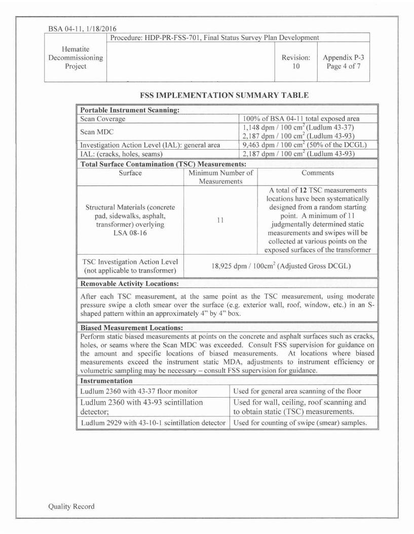
b. Mark the location(s) exhibiting anomalous readings to facilitate possible future investigations.
3. At each location where anomalous readings occur, perform a more detailed point survey of the area using the handheld probe (Ludlum 43-93). Pause and place the survey probe as close as possible to the surface to define and record the total count rate associated with the area of interest on the Field Log. If residual radioactivity exceeding the static MDA is detected at any special features of concern (cracks, holes, seams), contact FSS supervision for guidance. Adj ustments in instrument efficiency or volumetric sampling may be necessary.
4. Collect static count measurements at the 12 systematic (and any biased) measurement locations on contact with the structural surface for a period of l minute. Collect static count measurements at a minimum of 11 judgmentally determined measurement locations on contact with the transformer surfaces for a period of 1 minute.
5. At each TSC or static measurement location, after the alpha+beta static count has been completed, swipe a cloth smear over the surface (e.g. concrete, asphalt, transformer, etc.) with moderate pressure in an Sshaped pattern within an approximately 4,. by 4'' box (100 cm2).
6. Record all scan, direct measurements, and swipe data on Fonn Appendix A-1 and submit to the FSS Supervisor for review.
Volumetric Sampling
1. No volumetric sampling is anticipated as part of the FSS of BSA 04- 11 (see also General Instructions #7).
Prepared by: Brian A. Mil ler &'""7s4:HL c[relr l (Print Name) (Date)
Peer Reviewed by: El len C. Jakub ~ l -& -l (p (Print Name) (Date)
Approved by IJ f!fa__L I /;'l //lo (RSO): W. Clark Evers (Print Name) (Signature) I (bate)
Quality Record
Hematite
Decommissioning
Project
Procedure: HDP-PR-FSS-701 , Final Status Survey Plan Development
Revision: 10
APPENDIX P-2
Appendix P-2 Page 1 of 6
FINAL STAT US SURVEY SAMPLING PLAN DEVELOPMENT CHECKLIST FOR STRUCTURE SURVEY UNITS
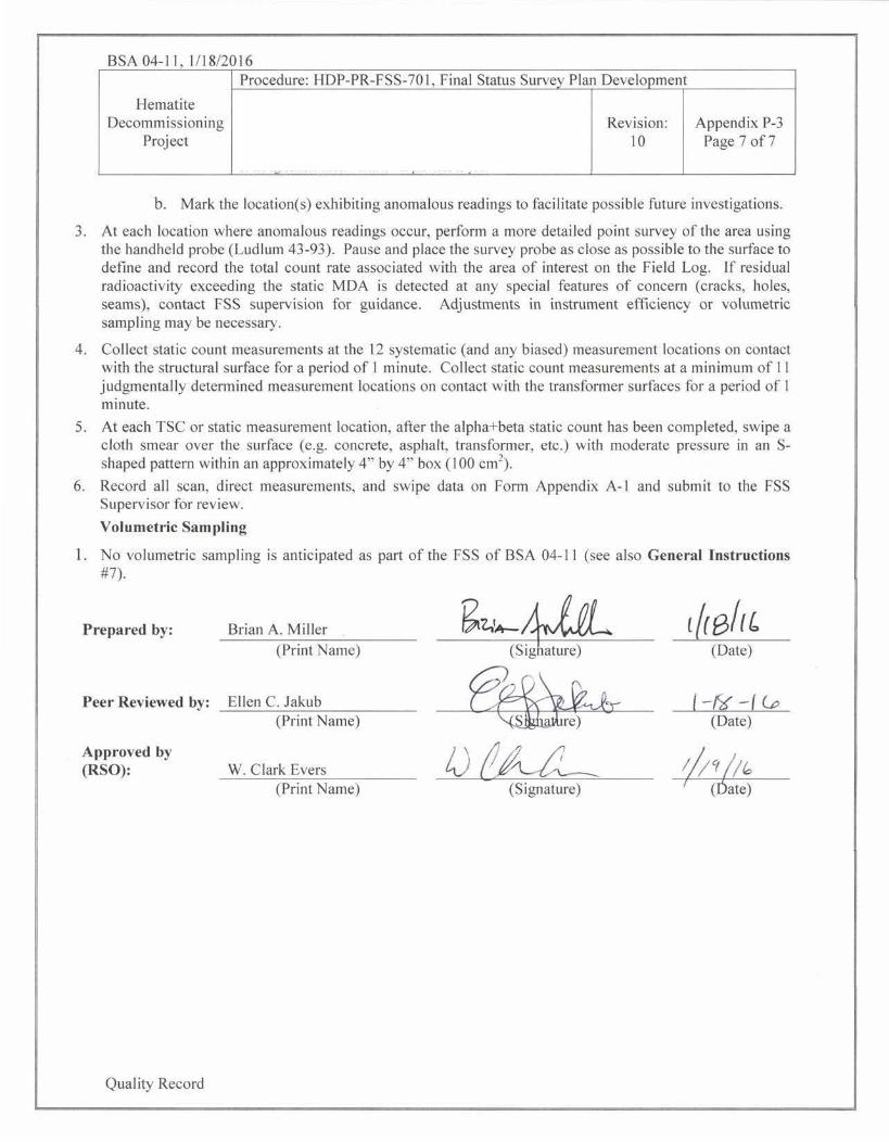
Survey Area BSA 04 Description: Structure Survey Unit in "Area 4"
Su rvey Unit I I Description: Concrete Pavement in LSA 08- 16
1. Survey Unit Isola tion & Cont rol
Has the Survey Unit been properly isolated and/or controlled (indicated by outlining the area with green rope and posting the appropriate signage) as required by HDP-PR-HP-602, Data Package Development and Isolation and Control Measures to Support Final Status Survey?
Yes~ No D
(lf"No", then discontinue survey design until area turnover requirements have been met).
2. Assessment of Characterization!Remedial Action Suppo1·t Surveys (RASS)
a. Derive & List the Basic Statistical Data for the TSC measurements in the characterization/RASS Survey Population.
#of Measurements Taken: ll
TSC Measurements
(dpm/100cm2)
Minimum 5
Maximum 577
Mean 157
Median 47
Standard Deviation 187.9
b. Is the characterization/RASS Survey Data sufficient to support FSS Design? Yes [gl No D (lf "No"', then terminate survey design and perform additional characterization or remediation and repeat the
pla1ming process.
Quality Record BSA 04-1 J

Hematite Decommissioning
Project
Procedure: HDP-PR-FSS-70 I, Final Status Survey Plan Development
Revision: 10
APPENDIX P-2
Appendix P-2 Page 2of6
FINAL STATUS SURVEY SAMPLING PLAN DEVELOPMENT CHECKLIST FOR STRUCTURE SURVEY UNITS
3. Survey Unit Classification
Write a short description of the survey unit based on historical use and remedial activities:
BSA 04-l l includes the surface of the concrete pad located in LSA 08-16. The surface of BSA 04-11 has a surface
area of 102 m2• It is classified as a MARSSIM Class I survey unit.
Initial Classification per DP Ch 14: Survey Unit Area: 102 m2
a. Has the Survey Unit Classification changed from the Initial Classification for the Survey Unit as described in DP Ch. 14?
Yes 0 No iX1
(lf"Yes" , then include a copy of Appendix P-5. Survey Unit Classification Change Form with the FSSP).
b. Is the Survey Unit area less than the maximum size for the Classification? Yes (8J No D (If "No", then terminate survey design and evaluate dividing the survey unit into multiple survey units).
4. Area Remediation
Select the appropriate remediation status for the Survey Unit.
0 No Remediation 0 System Removal
IX1 Structural or System Decontamination IX1 Structural Removal
5. Types of Samples and Measurements for FSS
Select the appropriate types of samples and measurements for FSS for this Survey Unit.
Statistical Sample Population
IX1 Total Surface Contam ination (TSC) measurements
IX1 Swipe Samples for Loose Surface Contamination.
Quality Record
D Volumetric Material Samples
0 Other
Scan Measurements
IX1 l 00% Scan Coverage of Exposed
Surfaces
0 ~% Scan Coverage of Exposed Surfaces
BSA 04-11

Hematite Decommissioning
Project
Procedure: HDP-PR-FSS-701 , Final Status Survey Plan Development
Revision: 10
APPENDIX P-2
Appendix P-2 Page 3of6
FINAL STATUS SURVEY SAMPLING PLAN DEVELOPMENT CHECKLIST FOR STRUCTURE SURVEY UNITS
6. Derived Concentration Guideline Levels (DCGL)
The Adjusted Gross DCGL for structural surfaces at HDP is 18,925 dpm/100cm2 per Table 14-7 of DP Ch. 14. This Table has been reproduced as Appendix C ofHDP-PR-FSS-701.
7. Determine the Number of Samples in the Statistical Survey Population
a. Set the Lower Bound of the Grey Region (LBGR) at the mean activity for the characterization/RASS survey data set from Step 2.
ActivityMean = 157 dpm/ l 00cm2 = Lower Bound of the Grey Region (LBGR)
b. Standard Deviation for the characterization/RASS survey data set from Step 2.
cr = 187.9
c. Define the Decision Errors.
Type l Error = 0.05 Type II Error = 0.10
Note: The Type II Error is set at 0.10 initially but it may be adjusted with RSO concu1Tence.
d. Determine the Relative Shift using the equation from Step 8.3.4c ofHDP-PR-FSS-701.
Relative Shift= 99.9
e. Is the Relative Shift between 1 and 3? Yes D No l:8J
(If "Yes", then continue to Step 7f, if "No", then proceed to the next step).
If the variability in the data set is acceptabte, then adjust the LBGR as necessary in order to achieve a Relative Shift between l and 3. In order to accomplish this. the LBGR may be set as low as the MDC of the instrument that will be used for the measurements.
Adjusted LBGR = 18,361
Adjusted Relative Shift = 3.0
f. Determine the Number of Samples (N) required corresponding to the Type I error, Type II ElTor and
Quality Record BSA 04- 11

Procedure: HDP-PR-FSS-701, final Status Survey Plan Development Hematite
Decommissioning
Project Revision: 10
Appendix P-2 Page 4of6
APPENDIX P-2 FINAL ST ATVS SURVEY SAMPLING PLAN DEVELOPMENT CHECKLIST FOR
STRUCTURE SURVEY UNITS
the Relative Shift from Appendix E of HDP-PR-FSS-701.
Number of Samples (N) = 11
8. Determine the Scan MDC
a. Identify the Radiological Instrument that will be used for scanning.
D Ludlum 43-89 Scintillation Detector Other Ludlum 43-93 Scintillation Detector
Ludlum 43-37 Floor Monitor
b. Determine the Scan MDC for the selected instrument using the equation from Step 8.3.5b of HDPPR-FSS-701.
MDCscan =
MDCscan=
2,190
1,150
dpm/ 100cm2 Ludlum 43-93
dpm/1 00cm2 Ludlum 43-37
9. Adjust the Statistical Sample Population Size (N) for Scan MDC
a. ls the MDCscan for the selected instrument less than the Adjusted Gross DCGL? Yes (gJ No D b. If the answer to the question in Step 9a is· "Yes" or the survey unit is either Class 2 or Class 3, then
proceed to Step 10. If the answer to the question in Step 9a is "No" and the survey unit is Class 1, then proceed to the next step.
c. Divide the total area of the survey unit by the Number of San1ples (N) calculated in Step 7f to calculate the area bounded by the statistical sample population (Asu).
Area Bounded by the statistical sample population (Asu) = 9.3
d. Select an Area Factor (AF) from Appendix I of HDP-PR-FSS-701 that corresponds to the area bounded by the statistical sample population (Asu).
AF for the Bounded Area (Asu) = NA
e. Multiply the Adjusted Gross DCGL Area Factor (AF) to derive an Adjusted Gross DCGLEMC·
Adjusted Gross DCGLEMC = NA dpm/100cm2
f. Is the MDCscan for the selected instrument less than the Adjusted Gross DCGLEMc?
Yes D No D NA IXJ
Quality Record BSA 04-11

Hematite Decommissioning
Project
Procedure: HDP-PR-FSS-70 I, Final Status Survey Plan Development
APPENDIX P-2
~~~~~~~~~~~-·
Revision: l 0 Appendix P-2
Page 5of6
FINAL STATUS SURVEY SAMPLING PLAN DEVELOPMENT CHECKLIST FOR STRUCTURE SURVEY UNITS
g. If the answer to the question above is "Yes", then continue to Step 10. If the answer to the question above is ·'No", then proceed to the next step.
h. Determine a new AF (AFEMC) corresponding to the MDCscan for the selected instrument by dividing the MDCscan by the Adjusted Gross DCGLw.
AFEMC corresponding to MDCscan = NA
1. Find the Area (A') that conesponds to the Area Factor (AFEMc).
A' corresponding to AFE.MC = NA
Note: The Area Factors for structures are found in Appendix I of HDP-PR-FSS-70 I.
J. Determine an Adjusted Number of Samples CNr:Mc) for the statistical sample population size that corresponds to the bounded AEMC using the equation from Step 8.3.6h of HDP-PR-FSS-70 I.
NEMC corresponding to A' = NA
N calculated in Step 7f = NA
k. ls Nr.:Mc > the value of N determined in Step 7f? Yes 0 No 0 NA~
(If "Yes", then use the larger NEMC value as the statistical sample population size. If no, then use the value of N that was calculated in Step 7f as the statistical sample population size).
10. Determine the Gl'icl Spacing
a. ls the Survey Unit a Class 3 Survey Unit? Yes 0 No~
(If ''Yes". then continue to Step I I, if ··No.,, then proceed to the next step).
b. Determine Grid Spacing (L) using the equation from Step 8.3.7b of HDP-PR-FSS-701.
Grid Spacing (L) for Survey Unit = 3.2 m
11. Generate a Survey Map
a. Assign a unique identification number to each measurement in the statistical sample population using the guidance and direction provided in Appendix M of HDP-PR-FSS-701.
Qua I ity Record BSA 04-11

Procedure: HDP-PR-FSS-701 , Final Status Survey Plan Development Hematite Decommissioning
Project
.....-------.------~
Revision: 10
APPENDIX P-2
Appendix P-2 Page 6of6
FINAL STATUS SURVEY SAMPLING PLAN DEVELOPMENT CHECKLIST FOR STRUCTURE SURVEY UNITS
b. Generate a graphic representation of the Survey Unit with dimensions and boundaries corresponding to an established reference coordinate system in accordance with Step 8.3.8 ofHDP-PR-FSS-701.
c. Using the reference coordinate system, ascertain coordinates for each sample location.
d. Designate measurement locations, and location coordinates on Appendix P-4, FSS Sample & Measurement Locations & Coordinates and attach a copy of that form to the FSSP.
e. Attach a copy of the developed Survey Map with sample locations to the FSSP.
12. Biased Measurements
a. Designate if any biased measurements will be taken at the discretion of the HP Staff designing the survey and the basis for taking them. Necessary biased samples will be explained on Appendix P-3, FSS Sampling Plan.
Note: Biased measurements are not included as part of the statistical sample population. Rather, they are treated as pre-emptive investigation measurements.
b. Using the reference coordinate system, ascertain coordinates for each biased measurement location.
c. Designate biased measurement locations, and location coordinates on attached Appendix P-4, FSS Sample & Measurement Locations & Coordinates.
13. Scan Coverage
a. The Survey Unit is: ~ Class 1 D Class 2 D Class 3
b. Based on the Survey Unit Classification, the scan coverage in this Survey Unit is;
~ I 00% Scan Coverage of Exposed Surfaces D ___ % Scan Coverage of Exposed Surfaces
14. Investigation Levels
a. The Survey Unit is: D Class 3
l) Scan Investigation Levels are set at the most limiting between the Adjusted Gross DCGLw = 18,925 dpm/I 00cm2 or the MDCscan for the instrument used.
NA dpm/ l 00cm2
2) TSC Measurement Investigation Levels are set at 50% of the Adjusted Gross DCGLw = 9,462 dpm/ I 00cm2
•
Qua I ity Record BSA 04-11

Hematite Decommissioning
Project
Procedure: HDP-PR-FSS-701 , Final Status Survey Plan Development
Revision: 10
APPENDIX P-2
Appendix P-2 Page 7of6
FINAL STATUS SURVEY SAMPLING PLAN DEVELOPMENT CHECKLIST FOR STRUCTURE SURVEY UNITS
b. The Survey Unit is: D Class 2
l) Scan In vestigation Levels are set at the most limiting between the Adjusted Gross DCGLw = 18,925 dpm/ l 00cm2 or the MDCscan for the instrument used.
NA dpm/ 100cm2
2) TSC Measurement Investigation Levels are set at the Adjusted Gross DCGLw = 18,925 dpm/ 100cm2.
c. The Survey Unit is: ~ Class 1
1) Scan Investigation Levels (general area) are set at 50% of the Adjusted Gross DCGLw =
Scan lnvestigation Levels (expansion joints, stress cracks,
floor/wall interface, penetrations) are set at the most limiting MDCscan fo r the instrument used =
9,463 dpm/100cm2
2, 190 dpm/ 100cm2 Ludlum 43-93
I , 150 dpm/ 100cm2 Lud lum 43-37
2) TSC Measurement Investigation Levels are set at the Adjusted Gross DCGLw = 18,925 dpm/I 00cm2•
15. FSSP Development Checklist Approval
Prepared by: Ellen C. Jakub ; - /<:o -/ (o (Print Name)
Peer Reviewed by: Brian A. Miller
(Print Name) (Date)
Approved by (RSO): W. Clark Evers
(Print Name) ' (Date)
Quality Record BSA 04-11

I !ematite Procedure: 11DP-PR-FSS-70 I. Final Status Survey P lan Development
' Decommissioning I Revision: 10
Appendix P-4 Project ' Page I or I
' -APPENDIX P-4
F SS SAMPLE & M E ASU REMENT LOCA T IONS & C OORDINATES
Survey Ar ea: BSA 04 Description: StTucture SurvC) Unit in "Arca 4"
Survey Unit: 11 Description: Concrete Pavement in LSA 08- 16
Survey Type: FSS Classification: Class I
Measurement or Sample Surface or Type
Start End Northing (feet) Easting (feet) Remarks I Notes
lD CSM Elevation Elevation (Y Axis)* (X Axis)•
B04-l l-O t -S-F-S-OO F s 433.0 432.5 864758.0 826976.0 Concrete
B04- I l -02-S-F-S-OO F s 433.0 432.5 864767 0 826971.0 Concrete
804-11-03-S-F-S-OO F s 433.0 432.5 864767.0 826982.0 Concrete
B04- 1 I-04-S-F-S-OO F s 433.0 432.5 864776.0 826976.0 Concrete
804- l l-05-S-F-S-OO F s 433.0 432.5 864776.0 827008.0 Concrete
804-1 1-06-S-F-S-OO F s 433.0 432.5 861785.0 826961.0 Concrete
804- l 1-07-S-F-S-OO F s 433.0 432.5 764785.0 826982.0 Concrete
804-1 1-08-S-F-S-OO F s 433.0 -1 32.5 764785.0 827002.0 Concrete
804-11-09-S-F-S-00 F s 433.0 432.5 764794.0 826987.0 Concrete
804-11-1 O-S-F-S-00 F s 437.0 436.5 864960.0 827102.0 Concrete
804-11-11-S-F-S-OO F s 437.0 436.5 864969.0 827107.0 Concrete
B04-I t -12-S-F-S-OO F s 437.0 436.5 864978.0 8271 13.0 Concrete
Elevations arc in feet above mean sea level • Missouri - East State Plane Coordinates [North American Datum (NAD) 1983) (Open Land Area). OR
Distance m feet from lower left corner of the surface (Structures), each surface has it's own {X.Y) = {0,0). OR
For piping the distance from the beginnmg of the survey unit. Surface: Floor= F: Wall = W: Ceiling = C: Roof= R CSM. Three-Layer {Surface-Root-Deep) or Unifonn Type: Systematic= S. Biased= B: QC =Q; Investigation = I
Quality Record

Draft Sample Loe Northing Easting Elevation
604-11-01-S-F-S-OO 864758 826976 433
604-11-02-S-F-S-OO 864767 826971 433
804-11-03-S-F-S-OO 864767 826982 433
804-11-04-S-F-S-OO 864776 826976 433
604-11-05-S-F-S-OO 864776 827008 433
804-11-06-S-F-S-OO 864785 826961 433
804-11-07-S-F-S-OO 864785 826982 433
604-11-08-S-F-S-OO 864785 827002 433
604-11-09-S-F-S-OO 864794 826987 433
604-11-10-5-F-S-OO 864960 827102 437
804-11-11-S-F-S-OO 864969 827107 437
604-11-12-S-F-S-OO 864978 827113 437
BSA 04-11 Systemati
Pipe Chase 2
BSA 04-1 102 m2 Pia
25 50 75 100 llllli:s:im:::. ___ c======---- Feet
N ~ ~ o