Embed Size (px)
Citation preview

Chapter 1
WELDING PROCESSES
1.1 INTRODUCTION TO WELDING PROCESSES
Modern welding technology started just before the end of the 19th century withthe development of methods for generating high temperature in localized zones.Welding generally requires a heat source to produce a high temperature zone tomelt the material, though it is possible to weld two metal pieces without muchincrease in temperature. There are different methods and standards adopted andthere is still a continuous search for new and improved methods of welding. As thedemand for welding new materials and larger thickness components increases,mere gas flame welding which was first known to the welding engineer is nolonger satisfactory and improved methods such as Metal Inert Gas welding,Tungsten Inert Gas welding, electron and laser beam welding have been developed.
In most welding procedures metal is melted to bridge the parts to be joined sothat on solidification of the weld metal the parts become united. The commonprocesses of this type are grouped as fusion welding. Heat must be supplied tocause the melting of the filler metal and the way in which this is achieved is themajor point of distinction between the different processes. The method of protectingthe hot metal from the attack by the atmosphere and the cleaning or fluxing awayof contaminating surface films and oxides provide the second importantdistinguishing feature. For example, welding can be carried out under a shieldcomprising of a mixture of metal oxides and silicates which produce a glass-likeflux, or the whole weld area may be swept clear of air by a stream of gas such asargon, helium or carbon dioxide which is harmless to the hot metals.
There are certain solid phase joining methods in which there is no melting ofthe electrodes, though heat is produced in the process. The melted and solidifiedcast metal is normally weaker than the wrought metal of the same composition. Inthe solid phase joining such melting does not occur and hence the method canproduce joints of high quality. Metals which are dissimilar in nature can also bereadily welded by this process. In the normal process joining of dissimilar metalswill present problems because of the brittle intermetallic compounds formed duringmelting. Since the work pieces are closely pressed together, air is excluded duringthe joining process.
The welding processes covered in this chapter are gas welding, arc weldingwhich includes manual metal arc welding (MMA), tungsten inert gas shielded arcwelding (TIG), gas metal arc welding (MIG, MIG/CO2), submerged arc welding(SAW), etc. High energy density processes like electron beam welding, laser beam

2 Welding Technology and Design
welding, plasma welding are also dealt with. Pressure welding and some specialwelding techniques like electro-slag welding etc. are also discussed in detail. Figure1.1 shows the broad classification of the welding processes.
Though the different processes have their own advantages and limitations andare required for special and specific applications, manual metal arc weldingcontinues to enjoy the dominant position in terms of total weld metal deposited.The TIG process produces the finest quality weld on all weldable metals and alloys.The arc temperature may be upto 20,000 K. Although TIG welding produces thehighest quality welds, it is a slow and expensive process. Metal inert gas weldingprocess (MIG) is economical with consumable electrode fed at a predeterminedrate.
Plasma arc welding (PAW) has made substantial progress in utilising the highheat energy of an ionised gas stream. The jet temperature can be as high as 50,000K. Foils down to a thickness of 0.01 mm can also be welded in this process andhence this process is more useful in electronic and instrumentation applications.
All the processes like TIG, MIG and PAW can be successfully used for eithersemi-automatic or automatic applications. But they are all open arc processes whereradiation and comparatively poor metal recovery put a limit on using high currents.High productivity and good quality welds can be achieved by submerged arcwelding process with weld flux and wire continuously fed. The slag provides theshielding of the weld pool with provision for addition of alloying elements whenevernecessary.
Electron beam welding and laser welding are classified under high energy densityprocesses. Figure 1.2 shows the heat intensity (w/sq.cm) and heat consumption(wh/cm) for different welding processes discussed above.
For efficient welding the power source should provide controlled arccharacteristic necessary for a particular job. In one case a forceful deeply penetratingarc may be required, while in another case, a soft less panetrating arc may benecessary to avoid ``burn through''. The welding process will also require aparticular type of power source. Table 1.1 gives the power source required forwidely used welding process. The process details are discussed in the following:
Table 1.1 Power source for arc welding process
Process Output Current Polarity
Characteristics
Shield metal variable AC or DC DCSP
arc, TIG, voltage DCRP
Submerged arc* AC
Flux cored constant DC DCSP
voltage DCRP
Gas Metal arc constant DC DCRP
voltage
*In some applications, the SAW process can use constant voltage DC also.

Welding Processes 3

4 Welding Technology and Design
Fig. 1.2. Heat intensity and heat consumption for different welding processes
1.2 DETAILS OF WELDING PROCESSES
1.2.1 Gas welding
The most important process in gas welding is the oxygen in the oxygen-acetylenewelding. Other fuel gases are also employed in the place of acetylene. Thetemperature ranges for different fuel gases are given in Table 1.2.
Table 1.2 Temperature ranges for different fuel gases
Fuel gases Max. Temp °C Neutral Temp °C
Acetylene 3300 3200
Mythyl acetylene 2900 2600
propadiene
Propylene 2860 2500
Propane 2780 2450
Methane 2740 2350
Hydrogen 2870 2390

Welding Processes 5
Oxy-acetylene welding process can be used for joining a variety of metals.Oxygen gas is produced from commercial liquefaction of air. The liquid air isallowed to boil and when nitrogen and argon escape, pure liquid oxygen is leftwith. The gas is compressed in cylinders at a pressure of 15 MPa.
Acetylene gas (C2H2) is produced by the reaction of calcium carbide (CaC2)with water (H2O).
CaC2 + 2H2O = C2H2 + Ca(OH)2
Acetylene gas has the tendency to explode if the pressure is increased. So thegas is dissolved in acetone (CH3–CO–CO3) liquid which acts as a solvent for thegas. One volume of acetone can absorb about 25 volume of acetylene peratmosphere. The acetylene gas is usually compressed at 1.7 MPa.
The acetylene cylinder will be packed with porous calcium silicate, so that theliquid is distributed in fine form and the gas is aborbed in an effective way. Thecylinders are fitted with fusible safety plugs made of a low melting alloy (meltingpoint around 97°C) which will allow the gas to escape if the cylinders are exposedto excessive heat.Flame characteristicsWhen acetylene burns with oxygen the reaction can be given in the form
2C2H2 + 5O2 = 4CO2 + 2H2OThus one volume of acetylene combines with 2.5 volume of oxygen. But in
practice, the volume ratio will be 1:1 from cost point of view.
Fig. 1.3 Combustion zones in gas welding
The normal combustion zones are shown in Fig. 1.3. The flame has two zones—an inner zone where the temperature will be high and is governed by the primaryreaction
C2H2 + O2 = 2CO + H2 + 105 kCal

6 Welding Technology and Design
and an outer zone where the carbon monoxide (CO) formed by the above reactionwill combine with oxygen according to the secondary reaction
2 CO + O2 = 2 CO2 + 68 kCal2 H2 + O2 = 2H2O + 58 kCalThus combustion takes place in two stages.1. Oxygen and acetylene (O2 and C2H2) in equal proportions by volume, burn
in the inner white cone. In the cone the oxygen combines with the carbon of theacetylene to form CO, while hydrogen is liberated.
2. On passing into the outer envelope of the flame, two separate reactionstake place as combution is completed. The carbon monoxide combines with oxygenfrom the atmosphere and burns to form carbon-di-oxide CO2. The hydrogen alsoburns with O2 from the atmosphere to form water vapour H2O.
Depending on the ratio of C2H2 : O2, three types of flame can be obtained asgiven below:
1. Reducing flame when C2H2/O2 is greater than one.2. Neutral flame when C2H2/O2 is equal to one.3. Oxidising flame when C2H2/O2 is less than one.The reducing flame (also called carburising flame) will have unburned carbon
which may be added to the weld during welding. Carbursing flame may be fit forwelding high carbon steel or for carburising the surface of low carbon or mildsteel.
Neutral flame is invariably used for welding of steels and other metals. Inoxidising flame the inner zone becomes very small and a loud noise will be induced.Oxidising flame gives the highest temperature possible. The maximum temperatureof oxy-acetylene flame is 3100-3300°C and the center of this heat concentration isjust off the extreme tip of the white cone. Oxidising flame will introduce oxygeninto the weld metal and so not preferred for steel. A slightly oxidising flame isused for welding copper base alloys, zinc base alloys, cast irons and manganesesteels.
The welding torch has a mixing chamber in which oxygen and acetylene willbe mixed and the mixture is ignited at the torch tip. The pressure of oxygen andacetylene can be equal and the hand valves are adjusted to get supply of gas undersufficient pressure to force in into the mixing chamber. Torches are also designedto operate with low acetylene pressure to enable to draw more completely thecontent from the acetylene cylinder. To extinguish the flame, the fuel gas shouldbe turned off first followed by the oxygen. In the event of back fires, the oxygenshould be turned off first to prevent the internal temperatures from being excessivelyhigh and damage the blow-pipe.
While welding plates of thickness less than 3mm, no filler wires are used. Suchwelding is known as puddling.
For larger thickness of plates a filler rod is used. The filler rod is held atapproximately 90 degrees to the torch. When selecting the filler rod the followingworking formula may be used.
upto 5 mm thick (butt weld) D = T/2

Welding Processes 7
for Vee welds upto 7 mm D = T/2 + 0.8 mmT is the thickness of the plate in mm and D is the filler rod diameter in mm.Welding can be carried out in two ways. One is that in which the torch moves in
the direction of welding with the torch inclined at 65 deg. to the weld deposit. Thisis known as forehand technique. In the back hand technique the torch will beinclined at 45 deg. to the unweld region as shown in Fig. 1.4.
Fig. 1.4 Welding methods in gas welding
In gas welding full penetration upto about 10 mm thickness can be obtainedand a single pass welding can be done. The weld geometries for different thicknessesare shown in Fig. 1.5.
Fig. 1.5 Weld geometries for different thicknesses in gas welding
(Sources: A.C. Davies, The Science and Practice of Welding, Vol 2,
Cambridge University Press, N.Y., 1989)

8 Welding Technology and Design
A weld puddle is established first by the gas torch. Then the torch is movedforward in different shapes, such as circular path, zig-zag path, oscillating pathetc., ensuring in each case that sufficient time is given to obtain maximumpenetration.
Gas welding is more suitable for thin plates and sheets as its flame is not aspiercing as that of arc welding. Welding time is also comparatively longer in gaswelding and heat affected zone (HAZ) and distortion are larger than in arc welding.The gases which are generally expensive are to be properly stored.
Oxy-acetylene flame can also be used for cutting operations, known as flamecutting. When iron is heated to a temperature of about 750-870°C, it reacts rapidlywith oxygen to form iron oxide whose melting point is lower than that of steel.The heat generated will be sufficient to melt iron oxides and also some free iron.The cutting torch has a central orifice of oxygen jet surrounded by several orificesof oxygen-acetylene mixture to produce the required heating. Thus oxygen supplyis ensured for the formation of iron oxides during the cutting operation.
1.2.2 Fusion arc welding
1.2.2.1 Shielded metal arc welding (SMAW) and submerged arc welding (SAW)
Shielded metal arc welding
Shielded metal arc welding (SMAW) is a manual process of welding and is acommon and versatile method used for joining shapes that cannot be easily set upfor automatic welding methods. In this method a solid electrode with an extrudedbacked-on-coating material is used. A typical SMAW method is shown in Fig.1.6.The arc is struck by short circuiting the electrode with the work piece. Weldingcurrent is chosen according to the electrode diameter, type of electrode, and thekind of welding job. The arc voltage is determined as function of the arc length. InMMA it will be very difficult to keep a uniform arc length. When welding with
Fig. 1.6 Shielded metal arc welding
(Courtesy : Welding Hand Book AWS, USA, 1966)

Welding Processes 9
basic electrodes, where metal transfer causes short circuit, the dynamic short circuitcurrent has to be limited to avoid evaporation and blowing apart of the drop. Theweight of the weld metal deposited per unit time is proportional to the currentintensity. The electrodes are thoroughly dried or baked after production, bacausemoisture will cause an unstable arc, heavy spatter and porosity in the weld metal.
The coating of the electrode has got several functions :(a) Electrode material burns off faster than the coating flux that forms a crucible
and this shields the arc from the atmosphere.(b) Flux removes the impurities from the molten metal.(c) A gaseous envelope developed by the decomposition of the ingredients of
the flux covers the molten weld pool, thereby protecting it from atmosphericcontact.
(d) During cooling, the slag formed on the top of the weld metal acts as aprotective cover against contamination by the atmosphere.
(e) It provides alloy addition to the weld metal.Flux also (a) helps to start and maintain the arc, (b) helps to deoxidise and
refine the weld metal, (c) helps to control the weld bead profile and reduce theweld spatter, (d) helps to control viscosity of the slag so that vertical and overheadwelding is made possible. Arc voltage and current intensity, thermal energy andmode of metal transfer are controlled by the coating.
The electric power source can be AC transformer or DC generator. Carbonsteels from 3 mm to 60 mm can be welded easily with work piece as one polarity.Power sources of constant current type having drooping characteristics are usedfor MMAW process. Power sources of the constant voltage type are not suitable.
The heat developed by the arc is given byW (joules) = V (volt) × A (amps) × t (sec)
If the arc is travelling at a speed of S mm/minute, the heat input rate (HIR) ofthe arc will be
HIR = V × A × 60/S Joules/mm length of the joint.Though AC or DC power source can be successfully used, DC power source is
suitable for all types of electrodes. With AC source some non-ferrous type and alow hydrogen ferritic type electrodes may not give a stable arc. Both starting andmaintaining a short arc will be easier with DC power. Vertical and overhead weldingon thick sections will be easier with DC. In DC straight polarity (i.e. electrodenegative) can be used for MMAW of all steels; but not for non-ferrous metals.With straight polarity, more of the arc heat is concentrated on the electrode andconsequently melting and deposition rates are higher, welding is more rapid andthe workd piece is less susceptible to distortion. Reverse polarity (electrode positive)is used with basic low hydrogen electrodes and for most non-ferrous metals. Forsheet metal welding, D.C. straight polarity minimises burn-through problemsbecause of its shallow penetration. D.C. however, can cause problems of arc blow,specially so when welding ends of joints, corners etc. A.C. does not present suchproblems.

10 Welding Technology and Design
The electrode size refers to the diameter of its core wire. Current range dependson the diameter of the electrode. For light job where over-heating must be avoided,small size electrodes (e.g. 1.6mm - 2mm) can be used with current 25 amps to 40amps. For heavy work where maximum heat for adequate fusion is necessary,electrodes of large size and high current capacity e.g., 5 mm - 6.3 mm with 240 -320 amps can be used.
The core wire is rimming quality steel. Semi-killed or fully killed steel whichgives the best performance is also used as it is cheap to produce. Rimming is themethod of deoxidizing the steel in the final stages of its production. The siliconcontent of rimmed steel is 0.03%, in semi-killed steel it varies from 0.03 - 0.1%and in killed steel it is over 0.1%. In the selection of electrode quality wire, thesilicon content should not exceed 0.03%. Rimming quality steel will give good arcstability, uniform melting, fine globular metal transfer. Sulphur in the core wirehas to be controlled (0.03%) as otherwise, it will lead to hot cracking. Manganeseaddition (upto 1%) will suppress the harmful effects of sulphur.
Standards are available regarding the types of electrodes to be used in MMAwelding for different kinds of steel. Following are some typical examples:
AWS A5.11981 Specifications for carbon steel covered arc welding electrodes.IS 815 1974 Covered electrodes for metal arc welding of structural steels.AWS A5.51981 Low alloy steel covered electrodesIS 1395 1982 Low and medium alloy steel covered electrodes.AWS 5.4 1981 Corrosion resisting Chromium and Chromium Nickel covered
electrodes(IS 5206 - 1969)
The electrode standards prescribe the tensile and impact properties and othersupplementary tests which are not related to the code symbols, but are meant toevaluate the performance of an electrode and its suitability for welding certaingrades of steel.
In welding high carbon and alloy steels, difficulties may be encountered due toincreased hardness and reduced ductility. Electrode core wire of the samecomposition as that of base metal should be preferred. Craters should never be leftunfilled. Low alloy steel electrodes are mostly basic low-hydrogen type coveringwith or without the addition of iron powder.
Chromium steels should be preheated to 280-320°C and annealed after weldingto restore normal hardness. Since chromium easily combines with oxygen to formoxides, the electrodes coating should produce fluid slag which can dissolve thechromium oxides.
In the case of chromium-nickel steels, the holding time at high temperature andthe heat input should be reduced to a minimum. Titanium or Niobium should beadded with the core wire of the electrode and titanium oxide is the usual fluxmaterial. Because of its high electrical resistivity stainless steel electrodes get rapidlyoverheated during welding. So the welding currents are lower (20 - 30%) for agiven size than for ordinary mild steel. D.C. power supply with electrode positiveis preferred for stainless steel electrodes as this will help good fusion of the electrodedue to high liberation of heat. The ferrite number of stainless steel electrode shouldbe in the range of 4 to 10.

Welding Processes 11
MMA welding technique can also be used for improving surface properties ofcertain components like resistance to friction, wear, impact, abrasion, erosion,oxidation and corrosion. In such cases surfacing electrodes - also known as hardfacing electrodes—are used as the filler rod. This technique can also be used forbuilding of worn—out components.Submerged arc welding (SAW)
Submerged arc welding is a method in which the heat required to fuse the metalis generated by an electric current passing through between the welding wire andthe work piece. The tip of the welding wire, the arc and the weld area are coveredby a layer of granular flux. A hopper and a feeding mechanism are used to providea flow of flux over the joint being welded. A conveyor tube is provided to controlthe flow of the flux and is always kept ahead of the weld zone to ensure adequatesupply of flux ahead of the arc.
Figure 1.7 shows a typical SAW process. The intense heat evolved by the passageof the electric current through the welding zone melts the end of the wire and theadjacent edges of the work pieces, creating a puddle of molten metal. The puddleis in a liquid state and is turbulent. For this reason any slag or gas bubble is quicklyswept to the surface. The flux completely shields the welding zone from contactwith the atmosphere. SAW can use much higher heat input and has slowersolidification and cooling characteristics. Also the silicon content will be muchhigher in submerged arc welding, if care is not exercised in selecting proper fluxmaterial. SAW can be used for welding of materials in higher gauges.
SAW has the advantage of high weld metal quality and smooth and uniformweld finish. Deposit rate, deposition efficiency and weld speed are high. Smokeand arc flash are absent in SAW. The operator's skill is minimum in SAW and it isextensively used in heavy steel plate fabrications.
Fig. 1.7 Submerged arc welding
(Courtesy: Welding Hand Book @ AWS, USA, 1966)
12 Welding Technology and Design
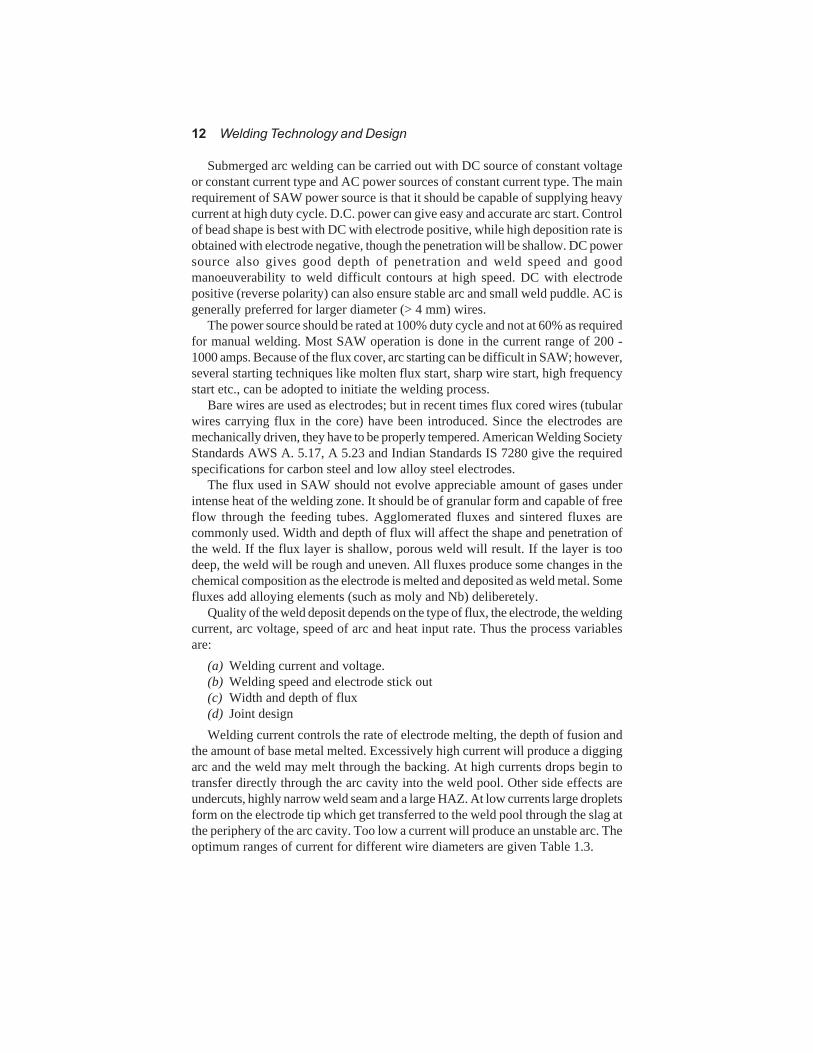
Submerged arc welding can be carried out with DC source of constant voltageor constant current type and AC power sources of constant current type. The mainrequirement of SAW power source is that it should be capable of supplying heavycurrent at high duty cycle. D.C. power can give easy and accurate arc start. Controlof bead shape is best with DC with electrode positive, while high deposition rate isobtained with electrode negative, though the penetration will be shallow. DC powersource also gives good depth of penetration and weld speed and goodmanoeuverability to weld difficult contours at high speed. DC with electrodepositive (reverse polarity) can also ensure stable arc and small weld puddle. AC isgenerally preferred for larger diameter (> 4 mm) wires.
The power source should be rated at 100% duty cycle and not at 60% as requiredfor manual welding. Most SAW operation is done in the current range of 200 -1000 amps. Because of the flux cover, arc starting can be difficult in SAW; however,several starting techniques like molten flux start, sharp wire start, high frequencystart etc., can be adopted to initiate the welding process.
Bare wires are used as electrodes; but in recent times flux cored wires (tubularwires carrying flux in the core) have been introduced. Since the electrodes aremechanically driven, they have to be properly tempered. American Welding SocietyStandards AWS A. 5.17, A 5.23 and Indian Standards IS 7280 give the requiredspecifications for carbon steel and low alloy steel electrodes.
The flux used in SAW should not evolve appreciable amount of gases underintense heat of the welding zone. It should be of granular form and capable of freeflow through the feeding tubes. Agglomerated fluxes and sintered fluxes arecommonly used. Width and depth of flux will affect the shape and penetration ofthe weld. If the flux layer is shallow, porous weld will result. If the layer is toodeep, the weld will be rough and uneven. All fluxes produce some changes in thechemical composition as the electrode is melted and deposited as weld metal. Somefluxes add alloying elements (such as moly and Nb) deliberetely.
Quality of the weld deposit depends on the type of flux, the electrode, the weldingcurrent, arc voltage, speed of arc and heat input rate. Thus the process variablesare:
(a) Welding current and voltage.(b) Welding speed and electrode stick out(c) Width and depth of flux(d) Joint designWelding current controls the rate of electrode melting, the depth of fusion and
the amount of base metal melted. Excessively high current will produce a diggingarc and the weld may melt through the backing. At high currents drops begin totransfer directly through the arc cavity into the weld pool. Other side effects areundercuts, highly narrow weld seam and a large HAZ. At low currents large dropletsform on the electrode tip which get transferred to the weld pool through the slag atthe periphery of the arc cavity. Too low a current will produce an unstable arc. Theoptimum ranges of current for different wire diameters are given Table 1.3.

Welding Processes 13
Table 1.3 Optimum range of current for different wire diameter
Wire diameter (mm) Current range (amps)
1.6 150 – 400
2.0 200 – 500
2.4 250 – 600
3.2 300 – 800
4.0 450 – 1000
5.0 600 – 1300
6.3 700 – 1400
High welding voltage will produce a wider, flatter, less deeply penetrated weld.A wider bead will increase the flux consumption. Low arc voltage will produce astiffer arc and may improve the penetration in a deep groove joint. However, slagremoval will be difficult in such cases.
The welding travel speed influences the weld size and penetration. High speedwill result in undercuts, arc blow, porosity and uneven bead shapes. The beadshape is essentially controlled by the welding speed. Too low a speed will produceheavy reinforcement and cause slag inclusions.
Electrode stick out is the length of the wire extending beyond the tip of thecontact tube above the work piece. Higher stick out will increase the depositionrate. However, too high a stick out will soften the wire due to heating and hencestiffness of the wire will be lost. Increased electrode stick out reduces the energysupplied to the arc, resulting in lower arc voltage and different bead shape. Thedepth of penetration is also decreased. Maximum electrode stick outs recommendedare
75 mm for 2.0, 2.4 and 3.2 mm wire dia.125 mm for 4.0, 4.8 and 5.6 mm wire dia.The heat input rate (HIR) affects the microstructure of the weld metal and HAZ.
The higher the heat input rate, the lower is the cooling rate of the weld and theHAZ of the parent metal. Weld and HAZ microstructure and toughness will bedependent on the HIR.
U and V weld joints can be used in SAW. Because of the high current used inSAW, a backing is always necessary for this process. The backing may be providedby means of flux, backing strip, or through the weld metal itself deposited byMMA process. The common defects encountered in SAW are slag inclusions,porosity and cracking of welds. The process variables mentioned may introducethese defects, if not properly adjusted to suit the welding condition.
Submerged arc welding is considered as an excellent and efficient process touse on nearly all ferrous metal welds of exceptionally good quality. Carbon, alloyand stainless steels upto 12 mm thick can be safely welded in single pass, whilethicker cross section requires multi-pass welding. Though the arc speed and themetal deposition rates are superior to other welding processes, the only limitationis the positional welding. Because a granular flux must be used to shield the weldmetal, in practice, only flat position welding is done or inclination upto 15° fromflat can be used.

14 Welding Technology and Design
Narrow gap welding in thick plates will reduce the weld metal deposit andwelding time. NGW can be successfully carried out by SAW (as well as the MIG/CO2) process. With the SAW process good shape welds without spatter can beobtained. However, slag removal between passes, visual inspection of eachindividual pass may become problems. In MIG/CO2 process of NGW, arc stability,effective gas shielding and the effect of magnetic fields on the arc may causeproblems. Narrow gap welding is best suited for circumferential joints of pressurevessels. The gap width can range from 15 mm to 22 mm, and suitable electrodesfor 3.2 mm to 5 mm dia are to be used. Wall preparation and joint fit-up requirehigh level of accuracy.Flux cored arc welding (FCAW)It is somewhat like submerged arc and shielded metal arc welding, except that theflux is encased in a metal sheath instead of being laid over the wire. The weldmetal is shielded by the metal flux and by a gaseous medium, either being externallysupplied or evolved from flux. Some cored wires have been designed for all positionwelding, but the weld puddle is still somewhat difficult to control, specially in theoverhead position. Carbon steel and stainless steel flux cored wires are available.A schematic diagram of flux cored wire welding process is shown in Fig. 1.8.
Fig. 1.8 Flux cored wire welding (Courtesy: The procedure Hand Book of Arc Welding @
The Lincoln Electric Co., Cleveland, USA, 1973).
Since the flux is in the core of the electrode wire itself, it helps in mechanisationof the welding process by introducing continuous wire feed. The flux coatedelectrode on the other hand fails in a situation where reeling or coiling of the wireis done. This is the major constraint in using covered electrodes in shapes of stickform.
The functions of the flux are the same as in MMA welding, i.e., it provides theshielding gas through chemical decomposition, acts as deoxidiser or scavenger toproduce sound weld metal, forms a slag which will float on the molten weld metal
Welding Processes 15
and protect it from atmosphere when solidification takes place, stabilizes the arcand in some cases can add alloying elements to the weld metal.
Flux cored arc welding can be carried out in both semi-automatic and fullyautomatic method. The flux cored arc process can be adopted with or without gasshielding. The metal transfer is in the form of (a) globular, (b) spray or (c) shortcircuiting. The flux in the core forms a molten slag as soon as the electrodeestablishes an arc and subsequently a weld pool. The arc is shielded by a gasevolved during the decomposition of the flux. A separate gas shield can also beused which will ensure a positive shielding of the arc. DC is used for flux coredwire. Constant voltage power with slope and inductance control is recommendedfor this process. Flux wire process gives faster deposition rate and lowers weldingcost. Fully automatic welding can be made in vertical seam welding. It can be agood substitute for electroslag or electrogas welding wherever the latter cannot beused effectively.
FCAW has high deposition rate due to stub elimination. Flux cored wire givesless spatter and improved weld finish due to arc stabilization and slag-formingcompounds at the core, which leads to less porosity. Flux core wires use standardtube materials and the required chemistry is achieved through alloy powderintroduced into the core. Flux core wires have great advantage in continuous hardfacing work and also in welding steel pipes involving 360° welding.
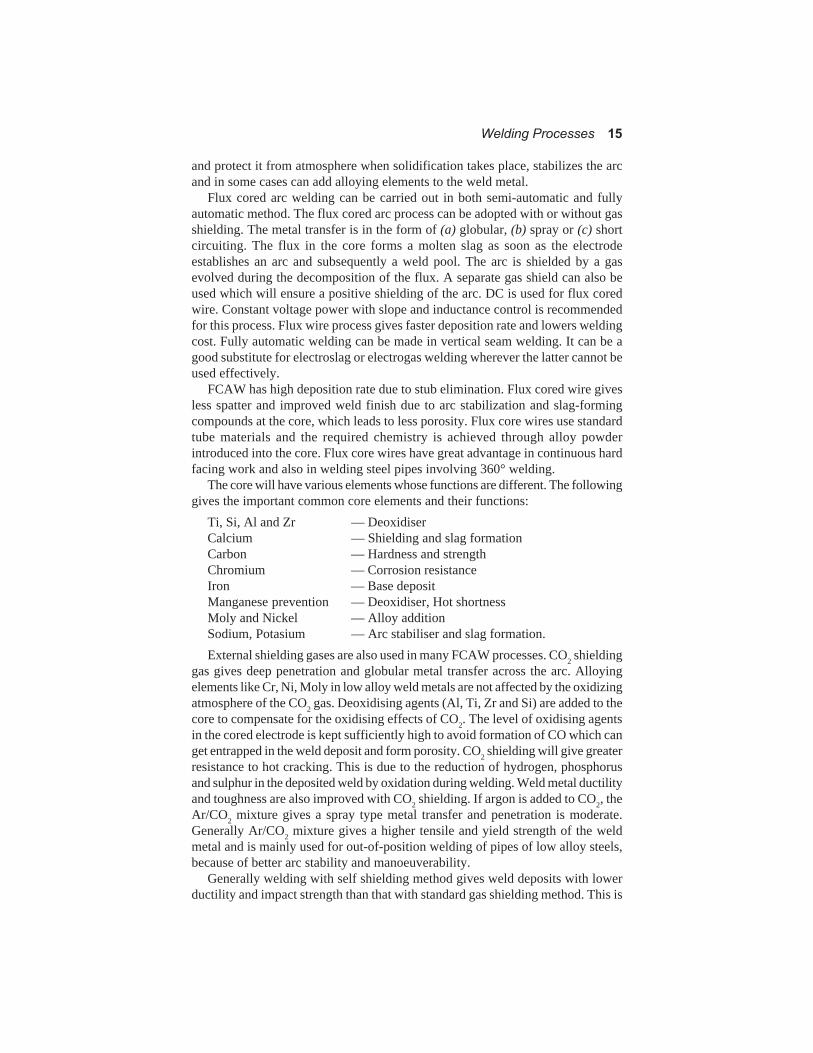
The core will have various elements whose functions are different. The followinggives the important common core elements and their functions:
Ti, Si, Al and Zr — DeoxidiserCalcium — Shielding and slag formationCarbon — Hardness and strengthChromium — Corrosion resistanceIron — Base depositManganese prevention — Deoxidiser, Hot shortnessMoly and Nickel — Alloy additionSodium, Potasium — Arc stabiliser and slag formation.External shielding gases are also used in many FCAW processes. CO2 shielding
gas gives deep penetration and globular metal transfer across the arc. Alloyingelements like Cr, Ni, Moly in low alloy weld metals are not affected by the oxidizingatmosphere of the CO2 gas. Deoxidising agents (Al, Ti, Zr and Si) are added to thecore to compensate for the oxidising effects of CO2. The level of oxidising agentsin the cored electrode is kept sufficiently high to avoid formation of CO which canget entrapped in the weld deposit and form porosity. CO2 shielding will give greaterresistance to hot cracking. This is due to the reduction of hydrogen, phosphorusand sulphur in the deposited weld by oxidation during welding. Weld metal ductilityand toughness are also improved with CO2 shielding. If argon is added to CO2, theAr/CO2 mixture gives a spray type metal transfer and penetration is moderate.Generally Ar/CO2 mixture gives a higher tensile and yield strength of the weldmetal and is mainly used for out-of-position welding of pipes of low alloy steels,because of better arc stability and manoeuverability.
Generally welding with self shielding method gives weld deposits with lowerductility and impact strength than that with standard gas shielding method. This is

16 Welding Technology and Design
because the level of deoxidising agents like Al, Ti will be more in the former case,which may promote bainitic structure in the weld affecting its toughness. Selfshielding wires are widely used in hardfacing.
AWS classification of Flux cored wires (AWS A5.20-1979) for welding C-Mnsteel gives the designated figures as
E x x T – for example E 6 O T – 8The first letter E designates electrode wire. The second letter 6 indicates the
tensile strength in ksi. In the example its value is 420 MPa. The third letter indicatesprimary welding position. e.g., O- flat and horizontal and 1 is for all positions. Inthe example it is flat and horizontal position. T stands for flux core wire and thelast figure indicates the weldability and performance capability. In the presentexample it shows the high crack resistance and good notch toughness at – 15°C.
The AWS specifications of the core wire areAWS A5.20 1979 Carbon steel electrodes for flux cored arc welding.AWS A 5.22 1980 Flux cored chromium and chromium-nickel steel
electrodesAWS A 5.29 1980 Low alloy steel electrodes for flux-cored arc welding.In general, increasing the welding current will increase weld deposit rate and
penetration. Low currents will produce large droplet transfer and spatter. Similarly,increase in arc voltage will result in spatter and a wide weld bead of irregularprofile. With self shielded electrodes this will result in excessive nitrogen pick-up.Low voltage will give shallow penetration. The electrode extension must be keptat optimum length, otherwise unsteady arc and spatter will occur. Similarly lowwelding speed will cause overheat of the base metal and will give rise to burn-through problems in thinner plates. Too high a speed will affect the bead profileand penetration. The electrode angle to the vertical (drag angle) should be between5° - 15° in gas shielded method and 20° - 45° for self shield method. FCAW isused extensivly for large scale hardfacing through automatic processes.
The main advantages of self shielded flux cored arc welding can be summarizedas follows:
(a) The deposition rate is around four times higher than that of stick electrodewelding.
(b) It produces crack free welds in medium carbon steels, using normal weldingprocedures.
(c) Mechanised welding is made easy.(d) It eliminates stub losses and the time required for electrode changes.(e) The process is adaptable to a variety of products.
1.2.2.2 Gas shielded arc welding
MIG and TIG
In gas shielded arc welding both the arc and the molten weld pool are shieldedfrom the atmosphere by a stream of gas. The arc may be produced between acontinuously fed wire and the work. This is known as metal inert gas (MIG) welding.
Welding Processes 17
The arc may also be produced between non-consumable tungsten electrode andthe work piece. This process is known as tungsten inert gas (TIG) welding. In TIGwelding extra metal must be supplied separately to fill the joint. For TIG weldingthe shielding gas is usually argon or helium, but for MIG welding the inert gasescan have additions of either oxygen or carbon-di-oxide depending on the metalbeing welded. Carbon steels can be welded with carbon-di-oxide alone as shieldinggas and the process is then called "CO2 welding''.
MIG welding (gas metal arc welding)
Gas metal arc welding is a gas shielded process that can be effectively used in allpositions. The shielding gas can be both inert gas like argon and active gases likeargon-oxygen mixture and argon-carbon-di-oxide which are chemically reactive.It can be used on nearly all metals including carbon steel, stainless steel, alloy steeland aluminium. Arc travel speed is typically 30-38 cm/minute and weld metaldeposition rate varies from 1.25 kg/hr when welding out of position to 5.5 kg/hr inflat position.
MIG welding is a well established semi-automatic process. Continuous weldingwith coiled wire helps high metal depositions rate and high welding speed. MIGgives less distortion and there is no slag removal and its associated difficulties likeinterference with accurate jigging. Because of the good heat input control, MIGcan be used for non-ferrous welding with good results. However, since the torchhas to be very near to the job, there is a constraint where accessability is limited.Spatter is high and so deposition efficiency is less. Absence of slag in solid wirewelding processes allows a higher cooling rate of the weld zone and hence jointsmade with the process on hardenable steels are susceptible to weld metal cracking.
The filler wire is generally connected to the positive polarity of DC sourceforming one of the electrodes. The work piece is connected to the negative polarity.The power source could be constant voltage DC power source, with electrodepositive and it yields a stable arc and smooth metal transfer with least spatter forthe entire current range. AC power source gives the problem of erratic arc. So isDC power source also with electrode negative. Power sources are rated at 60 percent duty cycle for semi-automatic and at 100 per cent duty cycle for automaticcontinuous operation with maximum amperage of 600 amps and 1000 to 2000amps respectively.
AC constant voltage power source, pulsed current constant voltage power sourceor pulsed current power source with voltage feedback controlled wire system arealso in practice. Among these, constant voltage power source is generally used.With a constant voltage power source, the welding current increases when theelectrode feeding rate is increased and decreases as the electrode speed is decreased,other factors remaining constant. When the current value is increased the meltingrate of the electrode will also increase.
Inert gas usually argon, helium or a suitable mixture of these is used to preventthe atmosphere from contacting the molten metal and HAZ. The core of the gascolumn ionized by the arc heat helps to maintain the arc. The metal transfer isaccomplished by (a) Short circuit transfer (dip transfer), (b) Globular transfer or

18 Welding Technology and Design
(c) Spray transfer: The current requirement will be of the order of 50 - 300 amps,and the voltage in the range from 16 to 45 V, depending on the type of metaltransfer.
Schematic diagram of the MIG process is shown in Fig. 1.9
Fig. 1.9 Gas metal arc welding MIG (Courtesy: The Procedure Hand Book of Arc Welding
@ The Lincoln Electric Co., Cleveland, USA, 1973)
CO2 gas is used as the shielding gas in GMA welding of steel plates. The flowcharacteristics of CO2 are such that the gas issues in a non-turbulent manner fromthe MIG gun. With CO2 shielding the metal transfer will be globular and non-axialat low current densities. Hence there will be considerable spatter. The non-axialtransfer is caused by an electromagnetic repulsive force acting on the bottom ofthe molten drop. MIG/CO2 welding with spray type arc (current density 350 amps)is best suited for welding relatively thick parts. For thin sheets dip transfer techniqueis used with low arc voltage (16 - 22 V) and low current (60 - 180 amps). The lowarc voltage results in a reduced arc length and the molten droplet gets transferredinto the weld pool by direct contact. With pure argon or a mixture of argon + 20%CO2, the metal transfer is globular at low current density, but changes to spraytype when the current density increases. In the spray type transfer the metal travelsacross the arc in the form of fine droplets which is induced by the magnetic forceacting on the molten electrode tip.
100 per cent pure argon is used for almost all metals except steels. Helium hashigher thermal conductivity. So it gives higher arc voltage for a given current andhigher heat input. However, helium being lighter (than argon and air) rises in atubulent manner and tends to disperse into air. So higher flow rate will be requiredin the case of helium shielding.
Addition of O2/CO2 with argon or helium causes the shielding gas to be oxidisingand may give rise to porosity in some ferrous metals. CO2 is widely used for weldingof mild steel and it gives sound weld deposits. In these cases the electrode mustcontain appropriate balance of deoxidisers such as Al, Ti, Si and Zr.

Welding Processes 19
MIG/CO2 process is extensively used for welding steels of different kinds. Fillerwire specifications are given in standards AWS 5.18/79 and AWS 5.20/79.
Aluminium alloy can also be welded by MIG and TIG processes. The standardfiller rods are given in AWS A 5.10 and IS 5897. Aluminium alloys welding isnormally done with spray type arc using steady current or pulsed current. Deeppenetration with proper root fusion can be obtained. Plates of different thicknessescan be welded easily with pulsed current welding technique. MIG can also be usedfor copper and its alloys. The filler rod specifications are given in AWS A 5.7 andIS 5898.
Pulsed MIG welding
In MIG there is a transition current below which the metal is transferred in a fewlarge drops by gravity and the penetration is shallow. Above the transition currentthe metal is transferred in many small drops by electromagnetic forces and thepenetration is deep. The power can thus be supplied in a pulse mode which canenable the current just high above the transition level and long enough time totransfer small droplets accompanied by deep penetration. The metal depositiontakes place when the current is at peak level. During low level current in the pulseperiod, no transfer of metal will occur. This process is known as pulsed currentMIG welding. Pulsed MIG can be used for all positions, for root pass withoutbacking and for joining thin plates. Pulsed MIG is best suited for aluminium andcopper with high thermal conductivity where rapid solidification occurs, whichmay cause lack of fusion in normal dip transfer MIG technique.
Hot wire MIG
The filler wire can be heated to increase the metal deposition rate. This process isknown as hot wire MIG welding.
The current passed through the filler wire in MIG has to(a) heat the filler to the melting condition,(b) set up an electromagnetic force which helps in drop detachment, drop size
and rate of transfer of the drop to the work piece,(c) maintain the plasma(d) wett-in the weld bead and the work piece to have proper penetration.
Plasma MIG
A non-consumable electrode with a suitable torch and a nozzle can be used toproduce the necessary plasma. With the help of a high voltage high frequencyspark, an arc can be initiated between the non-consumable electrode and the workpiece. The filler metal can be fed from a different convenient position. The non-consumable electrode and its constant current arc form the plasma MIG process.In addition there will be an anxiliary outer stream of a shielding gas, CO2, argon,helium, nitrogen, or a mixture of these gases. The additional plasma sheath inplasma MIG process makes it possible to use large electrode extension increasingthe deposition rate. Wetting-in of the base metal is improved. In aluminium welding,the quality of weld metal is improved by the cleaning action of the plasma arc onthe work piece. Table 1.4 gives the shielding gas for different base metals.

20 Welding Technology and Design
Table 1.4 Shielding gases for MIG
Argon For most metals except steel
Helium Aluminium and copper alloys
A+He(50%) Aluminium and copper alloys
A + 25%N2
Copper and its alloys
A + 1.2% O2
Alloy steels and stainless steels
A + 3.5 % O2
Carbon steels, alloy steels, requires deoxidised
electrodes
A + 25% CO2
Various steels, used with short circuiting arc
A + 5% O2 + 15% CO
2Various steels, requires deoxidised wire
CO2
Steels, requires deoxidised electrodes.
TIG welding
A non-consumable tungsten rod is used as the electrode with inert gases shieldingboth the molten metallic pool and the red hot filler wire tip. Argon or helium gas isused for shielding purposes. Argon is preferred for a wide range of materials, andas no flux is used, corrosion due to flux inclusions cannot occur. Almost all metalscan be welded using TIG process. Dissimilar metals can also be welded by TIGchoosing the appropriate combinations. These non-consumable tungsten electrodesare alloyed with zirconium or thorium (around 1%). Zr alloyed tungsten is used inalternating current applications and it has high resistance to contamination and hasgot good arc starting characteristics. Typical TIG process is schematically shownin Fig. 1.10.
Thoriated Ti electrodes have high emissivity, better current carrying capacityand longer life and normally preferred in DC welding. Pure Ti electrodes are usuallypreferred for AC welding of aluminium and magnesium. The current carryingcapacity is lower than that of alloyed electrodes.
The current carrying capacity of the electrode depends on the type of shieldinggas, the length of electrode, the cooling of the holders, position of the weld typeetc. If the electrode is large for specified current, the arc will become erratic andwelding will be difficult. However, selection of smaller diameter rods wouldincrease the chances of electrode melting.
Fig. 1.10 Gas tungsten arc welding TIG
(Courtesy : Welding Hand Book @ WAS, 1970)
Tungsten Electrode
(Non-consumable)

Welding Processes 21
TIG welding of stainless steel, nickel and its alloys may be carried out withargon and 5 per cent hydrogen. The hydrogen helps to increase the arc heatingefficiency and reduce the amount of oxides formed with stainless steel. In the caseof aluminium alloys a mixture of argon and helium can be used.
TIG welding can be done in almost all positions. Metal thickness ranging 1 to 6mm is generally joined by TIG process. TIG is often used for root pass in pressurecomponents and other critical applications, as it gives a clean and accurateweldment. In aerospace work the welds are made totally by multipass TIG welding,owing to the high quality demanded there. Aluminium alloys are generally weldedby TIG welding. Argon is the main shielding gas with some amount of helium.Preheating of aluminium alloys is necessary when TIG process employs AC powersupply. High alloy steels, copper, magnesium, Ni, Ti and Zr alloys can be readilywelded by TIG with AC power source. Pure inert gas atmosphere must be ensuredas some of these alloys (Ti and Zr) are highly reactive.
Gas tungsten arc welding produces the highest quality welds most consistently.It can weld all metals in any confirguration, but is not economically competitiveon heavy sections. It is most popular for welding aluminium and stainless steelpipe for nearly all process uses and specially in cryogenics where fusion is verynecessary. GTAW lends itself to more precise because the arc heat and filler metaladditions are controlled independently. But the process is slow and the arc travelspeed is 10cm/min and metal deposition rate 1 kg/hr. The concentrated heat inputof the TIG process helps to increase the welding speed, minimise distortion andimprove the metallurgical quality of the weld. In TIG the shielding gas (argon,helium or their mixture) gets ionised due to high frequency voltage superimposedon the welding current. The electrons which become free during the process ofionisation form a conducting path between the work piece and the tungstenelectrode. Thus the arc can be started without directly touching the tungstenelectrode to the work piece. In the case of DC power supply the high frequencyvoltage superimposition can be cut off once the arc is struck. In AC power, thehigh frequency voltage superimposition will be required continuously to improvethe arc stability in addition to the filter capacitor to be connected in series in theoutput circuit.
The arc voltage may range from 10-15 V with current 50-350 amps for argonand 15-25V with current 50-350 amps for helium shielding gas.
Tungsten has high resistance to heat and a high melting point (3410°C) and is astrong emitter of electrons which provide the arc path, ionize it, facilitating themaintenance of a stable arc. Specifications of tungsten electrode are given in AWSA 5.12-1980.
TIG welding is better suited for metal thickness of 7 mm and below. DC froma constant current type power source is used with electrode negative to deposit anarrow deep penetration weld. While welding the electrode tip must not be allowedto come in contact with the molten puddle. For initiating the arc high frequencystarting must be used.
Pulsed TIG welding
Pulsed TIG welding achieves a good control of heat input. The current from DCpower source is supplied in pulses having a predetermined duration for the peak

22 Welding Technology and Design
and low values.When the current is maintained at high on-position, welding takesplace with the required penetration. During the off-position, the torch is manipulatedto correct the positioning. The electrode is kept sufficiently hot and the ionisedcolumn is also retained so that the arc is not extinguished. In this process deeppenetration is obtained with less heat input to the joint. The pulsed arc agitates themolten weld metal and so minimises the porosity. Pulsing produces arc stiffnessand hence avoids arc wander. Molten weld pool can be well manipulated and,successive solidification of the nuggets avoids cracking and burn-through. Lesserheat input improves the grain structure and the mechanical properties of the weld.There is no need for weaving because the pulsed current is sufficient to melt therequired base metal area. Since the molten metal deposited in each pulse startssolidifying from the periphery towards the centre, the centre portion becomes proneto defects like segregation and shrinkage cracks. Pulsed TIG welding is suitablefor the root run of the tube and pipe welding. Thin plates and foils can be effectivelywelded by this process.
While joining precision parts by pulsed TIG, rapid current rise and currentdecay with a high pulse repetition rate is used. In mechanised TIG, slower rates ofcurrent rise and fall and slower current pulse rates are used.
The advantages of pulsed TIG are(a) variation in joint fit-up can be tolerated(b) welding of sheets down to 1 mm thickness can be carried out(c) distortion is minimised(d) position welding made easy(e) operator requires less skill(f) mechanisation is possible(g) ideal for critical applications like root passes of pipes, joining dissimilar
metals etc.
Hot wire TIG
Hot wire TIG welding is similar to ordinary tungsten inert gas welding except thatthe filler wire is heated prior to the deposition, either by resistance heating or byinduction heating. A high quality weld is obtained at a high deposition rate whichis controlled by adjusting the heating current of the wire. The dilution level is lowin this welding process. Since the wire is heated before entering the welding zone,the volatile surface contaminants of the filler wire get evaporated, thus eliminatinghydrogen, porosities, etc.
Spot TIG
Spot TIG is a process adopted to spot welding. Argon shielding is used in thisprocess. The current can be supplied in pulses and by proper timing spot weldswith defect free nuggets can be obtained.
Circumferential seam welding of pipes and tubes is carried out by orbital TIGwelding. Welding speed must be properly adjusted to suit variations in weld position,such as vertical-up, flat, vertical-down and overhead. Pulsed current is also usedfor orbital TIG.

Welding Processes 23
In automatic TIG welding magnetic control is used sometimes to controlsolidification. This control is effected by subjecting the arc and the weld puddle toa determined level of magnetic field. The arc stability is increased, defects areeliminated, penetration and dilution can be well controlled, grain refinement andmechanical properties can be improved by this method.
Both MIG and TIG can be effectively used for narrow gap welding (NGW), inwhich thick plates in the range of 50 mm to 350 mm thick can be welded to eachother with narrow U-type gap involving only 10 to 25 mm width and 2° to 4°included angle. The groove is filled with successive layers of weld metal with oneor two passes per layer.
Edge preparation in narrow gap welding is rather simple and quantity of fillermaterial consumption is less. Due to low heat input and multipass retempering,fine grained structure of weld is obtained. Residual stresses and distortion areminimum in narrow gap welding. However, the MIG and TIG equipments meantfor narrow gap welding are more complex and costly. Repair of defects will bedifficult. Cleaning the weld surface after each layer is laid, is also difficult. Sidewall fusion must be properly ensured. The process requires high accuracy of powersupply characteristics and close tolerance for electrode tip to work distance. Slaginclusion and lack of fusion in the side wall are the most common defects in NGW.Weld quality is more sensitive to welding condition than in conventional weldingmethods.
Different materials, particularly those sensitive to heat input, including HSLAsteels, stainless steels, aluminium and titanium alloys can be welded by NGW.Large structures, components like shells, drums, steam pipes, pressure vessels,power plant components, penstocks etc., are among the variety of productsfabricated by narrow gap welding process.
1.2.3 Electrical method
1.2.3.1 Electric resistance welding
Heat is produced by the passage of electric current across the interface of thejoint. It may also be induced within the metal near the joint. Typical examples ofthis type of joining are spot and seam welding where sheet metals are pressedtogether at the joint by copper alloy electrodes and, projection welding where themetal itself is shaped so that local contact at the joint concentrates the currentflow, thereby producing heat. Electro-slag welding which makes vertical joints, isin effect a continuous casting process employing electric resistance heating of abath of molten slag carried above the weld pool.
Electric resistance welding is a nonfusion welding process. Heat is generatedwhen high electric current is passed through a small area of the two contactingmetal surfaces. The heat H generated is given by
H = I2 × R × twhere I is current, R is resistance of the interface and t is the time of application ofcurrent. When the rise in temperature is sufficient, a large pressure is applied at theheated interface to form a weld joint. The process variables are : current, time ofapplication of current, pressure, duration of pressure applications, materials to bewelded and their thickness.

24 Welding Technology and Design
There are five main types of resistance welding:(a) spot welding(b) seam welding,(c) projection welding,(d) upset butt welding and(e) flash butt weldingIn spot welding the plates to be welded are kept one over the other, after cleaning
the two surfaces in contact. Two stick electrodes are kept on both sides of theplate, as shown in Fig. 1.11. A pressure is applied to the electrodes and maintainedfor a particular interval known as sqeeze time before starting further operation.Then the current is passed through the electrodes. The time of application of currentknown as weld time is measured in terms of the number of cycles, each cyclecorresponds to 20 m.sec. (1/line frequency). The pressure is maintained duringthis time also. After the current is cut off, the pressure is maintained for a brieftime known as hold time, so that the heated metal solidifies and forms a weldnugget. After hold time, the pressure will be released and an off-time is givenbefore starting another spot welding operation.
Fig. 1.11 Schematic diagram of spot welding
Too high a current will cause weld expulsion, cavitation and weld cracking,reduced mechanical properties and electrode embedment in the surface. On theother hand, less current will result in unfused surface and poor weld. High pressurewill increase the contact and decrease the contact resistance and so less heat willbe generated. It may lead to distortion and reduced electrode life. More time ofapplication of current may lead to boiling, porosity, growth of nugget upto electrodeface.
When two plates of different thicknesses are welded, the weld nugget growstowards the thicker side. So also, when two plates of different conductivity arewelded, the weld nugget grows towards the higher resistivity side. In these cases,the upper and the lower electrodes are chosen to be of different diameters.

Welding Processes 25
In the case of plates with thickness “t”, the electrode diameter “de” is taken asde = (0.1 + 2t) mm
Mild steel plates upto 10 mm can be easily spot welded. In the case of aluminiumthe upper limit is 6 mm plates and for copper it is 1.5 mm thick. The conductivityof the materials plays an important role in deciding the thickness of the plates thatcould be easily welded by spot welding. Spot welding of high carbon steels requiresPWHT. Spot welding is extensively used in aircraft industries, auto and instrumentindustries.
The main advantage of spot welding are(a) its adaptability to mass production,(b) high speed of operation,(c) cleanliness,(d) no welding rods and less operational skillMaterials having high thermal and electrical conductivities will be difficult to
weld by spot welding and require special procedure.In seam welding roller type of electrodes are used as shown in Fig. 1.12. The
rollers are rotated over the job as the welding proceeds. By controlling the powersupply it is possible to obtain a good heat control. The seam cools under pressureat definite intervals. The weld will have less surface disturbances.
As the welding proceeds the applied current will try to pass through the alreadywelded portion, thus reducing the heating in the portion to be welded. One way ofovercoming this difficulty is to increase the current as the welding progresses.Sometimes external heating like high frequency heating to offset the effect ofreduced current due to shunting can also be adopted.
The applied pressure in seam welding may range from 3 MPa to 8.5 MPadepending on the thickness of the work piece. The current density may be as highas 775 amps/sq.mm. The heat generated during welding will be high and the rollersmust be cooled by using water cooling arrangements, so that distortion of rollerscan be avoided. Current interruption can also be employed so that the current shall
Fig 1.12 Seam welding

26 Welding Technology and Design
flow for a specific time to supply the requisite heat to the weld and then shall ceasefor another predetermined length of time before the next spot weld is begun. Inthis way the heating of the rollers can be controlled.
Seam welding can be carried out on steels, aluminium, magnesium and nickelalloys. Seam welding of copper and its alloys is not recommended. High frequencyseam welding is suitable for finned tubes and other tubings.
Projection welding is similar to spot welding excepting that welding is carriedout at places in the sheet or plates where there are projections made for this purpose.The projections are created by pressing at the selected places in the sheet. Resistanceto heat being confined to the projections, welding between the parts takes place bythe application of adequate pressure at the appropriate time at these point of contact.Projection welding is particularly applicable to mass production work, and is quitesuitable where many spot welds are required in a restricted area. Projection weldingmethod is used in welding brackets, heavy steel stampings, in the encapsulation ofthyristers etc.
Upset butt weld is obtained by bringing two pieces of metals to end-to-endcontact under pressure and then allowing current to flow from one piece to theother. The contact surfaces should be as smooth as possible. In upset welding (asalso in flash butt welding) a forge structure results as against the cast structureobtained in spot and projection welding. Welding of tools to the shank is carriedout by upset welding. Resistance butt welding is employed for joining tubes asschematically shown in Fig. 1.13.
Fig. 1.13 Resistance butt welding.
In flash butt welding the two pieces to be welded are pressed against each otherby applying a pressure so that contact will be at points due to surface roughness. Ahigh welding current is passed. The surfaces are heated upto molten condition,and as one piece is slowly advanced towards the other the molten metal is flashedout. After the faces attain plastic stage upsetting pressure is applied, leading tobonding of the two faces. Flash butt welding is different from resistance pressurewelding in the sense that in flash butt weld contacts between the two surfaces aremade at some point only due to the roughness of the surface. In resistance buttweld a smooth full contact surface is preferred.

Welding Processes 27
In flash butt welding surface contaminations are removed in the spatter duringflashing and molten metal is expelled in the final upset of forging operation. Asmall fin is created at the weld joint consisting of the remaining molten metal andoxides. This fin can be trimmed off by grinding. The advantage of this process liesin the fact that the molten metal and the arc afford an efficient protection to theplastic metal which ultimately forms the weld, so that the danger of oxidation canbe avoided.
The applied pressure in the cold (not preheated) condition may range from 70MPa for low alloy and mild steels to 110 MPa for medium carbon steel and 177MPa for stainless steel and tool steels. With preheating, the applied pressure canbe reduced to approximately half the above values.
Flash butt welding is easily applied to highly alloyed steels which cannot bewelded by other process satisfactorily. Flash butt welding is cheap and simple. Itcan be readily used for small sub-assemblies as in motor car industries. The cost ofcurrent per weld is small and production rate will be high.
Fig. 1.14 Electro-slag welding process

28 Welding Technology and Design
Flash feed rate must be properly controlled. Insufficient or intermittent flashingwill result in poor heating. Flash time and flashing current should also be to theoptimum level. Plasticity induced due to heating should not be very high or toolow. Too high an upset force will result in too much of flashing leading to poorweld. If upsetting force is less oxides, inclusions and voids can be found in theweld.
Flash butt welding is used in solid and tubular structural assembly, gears andrings, super heater tubes in boiler etc.
1.2.3.2 Electro-slag welding (ESW)
Electro-slag welding offers good productivity and quality in heavy structuraland pressure vessel fabrications. The weld metal in ESW process is obtained byfusion of electrode wire under the blanket of flux layers. The heat for melting isobtained as resistance heat by passage of current through slag pool covering thecomplete surface of the weld metal. The schematic diagram of the ESW process isshown in Fig. 1.14. A pool of molten slag is formed between the edges of the partsto be welded and the travelling moulding shoes. The metal electrode is dipped intothe molten slag. The current passing through the electrode and the molten slagheats up the slag pool. The slag melting point is higher than those of the wire andthe parent metal. Hence the electrode wire melts and the molten metal settles at thebottom of the slag pool and solidifies to form the weld metal. To keep weldingstable, it is necessary for the slag pool to maintain its temperature.
In electro-slag welding the slag pool is 40-50 mm deep and it offers a conductivepath between the electrode and base metal. Thus the current flow is maintainedafter the arc is extinguished. In contrast, in the case of submerged arc weldingwhich appears to be similar to ESW, the arc remains stable under the molten slag,as the arc voltage is around 25-30 V, and the slag layer is rather shallow.
Both non-consumable and consumable guides are used in ESW. The first methodhas a contact tube which directs the wire electrode into the slag bath. The weldinghead moves upwards steadily along with the shoes as the weld is deposited. In theconsumable guide arrangement, a consumable tube is used. The welding headremains fixed at the top of the joint. The axis of the weld is vertical. The weldingmachine moves upwards consistant with the deposition rate. The amount of slagremains constant. A small amount of flux has to be added to the slag. When theweld is complete the welding machine can be withdrawn.
The welding wire chosen must match with the base material and the diameter isgenerally of the order of 3-4 mm. The flux should have high boiling point toenable melting of base metal and the welding wires. It must have good conductivtyand viscosity so as to maintain the temperature of the slag pool and to prevent theflow of the slag through gaps between work piece and the cooling shoes.
The ESW process is completely continuous and so productivity will be faster.No edge preparation of the parts to be joined is necessary. There will be saving inthe quantity of filler metal and the flux. After the welding process, the weldedcomponents require heat treatment. The process should be continuous and shouldnot be interrupted due to power failure etc. Otherwise the molten metal will shrinkforming a cavity at the centre. Normally other defects like slag inclusions, porosity,undercuts, notches etc., are not encountered in ESW process.
Welding Processes 29
Constant potential power source with 750-1000 amps at 100 per cent duty andwith a open circuit voltage of 60 V minimum is used. The electrode could be solidor flux-cored fed at a rate of 20-150 mm/second.
The quality of weld in ESW depends on (a) the ratio of width of the weld pooland its maximum depth, known as Form Factor, (b) weld current and voltage, (c)electrode extension and oscillation, (d) slag depth, (e) number of electrodes andtheir spacing etc. The weld will be more crack-resistant if the form factor is high.Weld voltage controls the depth of fusion. Increasing voltage increases the depthof fusion and the width of the weld. Increasing welding current will increase thedeposition rate and also the depth of molten weld pool. However, too high a currentmay result in deposits which will be crackprone.
Oscillation of electrode will ensure proper heat distribution and fusion. Theslag bath depth should be sufficiently deep so that the wire enters into it and meltsbeneath the surface. With shallow bath the slag will split and arcing will occur atthe surface. For best results the bath depth should be around 40 mm.
The electrode can be solid and metal-cored. AWS 5.25-1978 gives thespecifications of flux wire combination for ESW of carbon and high strength lowalloy steels. In ESW, the dilution is to the extent of 30 - 50 per cent by the basemetal. Hence care should be taken to select the proper wire for a particular steel.Many of the solid electrodes are the same as with SAW and MIG/CO2 welding.
The flux used must be conductive and must have proper viscosity to permit agood stirring action in the flux pool. The flux must have a melting range lowerthan that of the weld metal and metallurgically compatible with the alloy beingwelded. A basic flux is usually employed for carbon steel, low alloy steel andstainless steel. Fluxes are classified on the basis of the mechanical properties of aweld deposit made with a particular electrode.
Plates and other heavy sections upto 450 mm are commonly welded by electro-slag process. Heavy pressure vessels for chemical, petrochemical and powergenerating industries are usually welded by ES process only.
In ESW, the weld metal stays molten for a long time and permits slag-refiningaction, namely, escape of dissolved gases and transfer of non-metallic inclusionsto the slag-bath. The prolonged high temperature and the slow cooling rate inESW result in a wide coarse grained HAZ having relatively soft high temperaturetransformation products. The weld itself will have columnar cast structure. Assuch the toughness of the weld and HAZ will not be very high and if the servicecondition does not require high toughness the weld as such can be made use of.However, if the service condition requires high toughness of the weld, then propernormalising heat treatment must be carried out, so that all traces of cast structureare removed and toughness properties are improved.
1.2.3.3 Induction pressure welding
This is a solid phase welding, obtained by the use of high frequency inductionheating and by simultaneous application of pressure. Oxidation is avoided bypurging with hydrogen gas. The surfaces to be joined are heated by inductioncurrent at 4kc/sec, produced by an inductor in series with two capacitors, poweredby a transformer with two high frequency alternators. A typical seam welding of a

30 Welding Technology and Design
tube is schematicaly shown in Fig. 1.15. The induced current flows in a longitudinalloop along the edges to be welded, heating them uniformly through their thicknessover a certain length. Forging rolls, then weld together the fused lips, leaving aslight external flash, which is removed afterwards. The normal speed of weldingwhich depends on the power supplied, is around 15 meters per minute.
Induction pressure welding is extensively used in joining boiler grade Cr-Mosteel tubes. Figure 1.16 (a) shows the IPW process in welding of two tubes. 100kVA, 10 kHz IPW machine is used in welding a 50 mm diameter and 5 mm wallthickness tubes of 2.25 Cr- 1 Mo steel in the boiler industries. One tube is clampedin a fixed platen, while the other tube is in a moving platen. These tubes are pressedtogether by applying pressure through hydraulic system. The joint is inductionheated and hydrogen gas is purged around the weld joint to prevent formation ofoxides and to keep the induction housing cool. A typical weld cycle including thesoaking periods, is shown in Fig. 1.16(b) The peak temperature in the productionis 1275°C with an upset of 2.5 to 3 mm.
Fig. 1.15 Induction pressure welding process of a tube
1.2.4 Energy method
1.2.4.1 Electron beam welding (EBW)
Electron beam welding is a process in which the heat required to produce fusionis obtained from the impact of a high velocity high density stream of electrons onthe work piece. Upon impact the kinetic energy of the electrons is converted tothermal energy causing both vapourisation and melting. The vapourisation of thematerial beneath the beam enables the beam to penetrate into the material to bewelded, with the beam and the vapour forming a hole. As the beam moves alongthe joint, the molten metal flows round the hole leaving the welded joint in thewake of the beam. A schematic diagram of the process is shown in Fig. 1.17.

Welding Processes 31
Fig. 1.16 IP welding of Cr-Mo boiler tube. (b) Variations in Weld parameters
Fig. 1.17 Electron beam welding process
The EB weldings have depth to width ratio of more than 10:1 due to the extremelyhigh heat concentration. The beam is very narrow, less than 0.25 in diameter andthe welding speed is high. The net heat input is very low.
The electron emitter is a cathode - anode system in a very high vacuum chamber.The cathode is made of tantalum or tungsten and heated to about 2560°C. Electron

32 Welding Technology and Design
cloud is thus created near its surface. A metallic shield, known as Wehnelt, is fixednear the cathode to make the electric field sharper and regulate the electron flow.
The electric field between cathode and anode accelerates the electrons and setsthem free with considerable energy. Thus an electron beam is created which ismade to impinge on the parts to be welded. Magnetic lenses are used to focus thebeam on the work piece. Magnetic coils are also used for beam deflection andmanipulation of the beam spot on the work piece.
The speed of welding which depends on the width and depth of the weld mustbe properly controlled as, otherwise, it will lead to either incomplete penetrationor overheating. As the fusion zone in the weld joint is very narrow, there will bevery small disturbances in the base material. Shrinkage allowance to be given inthe design is small compared to other arc welding and the residual stresses producedin the component are also small. As the focal length of the EB system is quite high,the EB gun can be placed at a distance, as farther as one meter from the workpieces, unlike in electric arc or plasma jet welding. Thus welding narrow andrestricted area is possible with EBW. Welding can be done over a wide range ofthicknesses (0.1 mm to 100 mm) and dissimilar metals can be easily welded by theprocess due to precise heat control. Welding speed in EB is much higher thanelectric arc methods, thus reducing the welding time. Also the repeatability of EBwelds is high compared to other processes.
In EB welding the weld zone narrows down from the upper bead to the lowerbead. The metal vapour generated at the centre of the molten column may not beable to escape through the narrow slot at the bottom of the joint interface. Thuswhen the molten metal solidifies, root porosity may form in EB welds.
In deep penetration welds, it will be difficult to achieve fusion of the wholedepth. To get heating lower beads, weld parameters selected should be greaterthan those set for truly narrow weld. Backing support to the lower bead will helpin achieving a full penetration joint. The backing can be removed after welding.
The gun-to-work piece distance depends on the vacuum in the gun chamber. Atabout a vacuum of 10–4 torr, a sharp focus over a greater gun-to-work piece distancecan be achieved. When the chamber pressure is 10–3 torr, electron scattering becomessignificant, resulting in wide bead with lower penetration. Thus welds made in ahigh vacuum are narrower with narrow HAZ than those welds made in mediumvacuum (10–1 to 10–2 torr) or at atmospheric pressure. High vacuum welding, thoughtakes longer time (to achieve the required vacuum level) is good for reactive materialwelding.
Because of the narrow welds and HAZ, the residual stress and strain fieldsproduced are comparatively small and this reduces the cracking tendency of theweld. High welding speed attainable in EBW helps in achieving a weld with grainboundary condition almost free from liquation in the HAZ. Thus cracking can beavoided immediately after welding or on PWHT. When welding refractory alloysof high melting point, EBW reduces the grain growth substantially leading toimprovement in tensile strength and ductility.
The fusion zone in the EB weld is effectively a fine grained cast structure, oftenwith directional solidification towards the centre line of the weld. The solutiontreated areas are narrow and the overaged regions in the base metal is almost

Welding Processes 33
undetectable. A low temperature ageing treatment is sufficient to recover the originalstrength after welding. This property of EBW is very useful for welding ofaluminium alloys.
Non-ferrous metals such as aluminium and titanium alloys are welded at above50 mm/second welding speed to suppress gas evolution, and steels at lower speedsto allow adequate time for vacuum degassing of the weld pool. Due to the fastercooling rate of EBW, hardness in the weld zone will be high. This may not bedesirable in some steels, as it will lead to quench cracking. To avoid such crackingPWHT has to be carried out.
In case EB weld does not penetrate fully, a blind weld results. In such situations,the molten metal is unable to flow into the penetration cavity and wet the sidewalls of the work pieces. This will result in cracking, known as “Necklace Cracking”and has been noticed in all meterials such as Ti alloys, stainless steels, nickel basealloys and carbon steels. This defect can be eliminated by widening the weld,which will enable the material to flow into the cavity and reduce temperaturegradient and the cooling rates. Initial cost of EBW machine is very high. Further,EBW can be used only in an automatic operation owing to high speed of welding.However, significant machine time and material saving can be achieved by EBW.
1.2.4.2. Laser beam welding
Laser beam welding is a high energy density welding process with low heatinput. A wide variety of metals and alloys can be welded by this process. The heatsource is a focussed beam of high energy monochromatic and coherent stream ofphotons and this process does not require vacuum chamber.
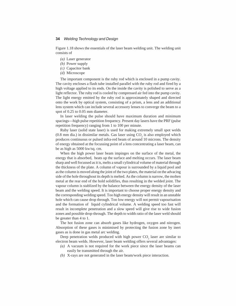
Fig. 1.18 Laser beam welding process
34 Welding Technology and Design
Figure 1.18 shows the essentials of the laser beam welding unit. The welding unitconsists of
(a) Laser generator(b) Power supply(c) Capacitor bank(d) MicroscopeThe important component is the ruby rod which is enclosed in a pump cavity.
The cavity encloses a flash tube installed parallel with the ruby rod and fired by ahigh voltage applied to its ends. On the inside the cavity is polished to serve as alight reflector. The ruby rod is cooled by compressed air fed into the pump cavity.The light energy emitted by the ruby rod is approximately shaped and directedonto the work by optical system, consisting of a prism, a lens and an additionallens system which can include several accessory lenses to converge the beam to aspot of 0.25 to 0.05 mm diameter.
In laser welding the pulse should have maximum duration and minimumspacings—high pulse repetition frequency. Present day lasers have the PRF (pulserepetition frequency) ranging from 1 to 100 per minute.
Ruby laser (solid state laser) is used for making extremely small spot welds(0.8 mm dia.) in dissimilar metals. Gas laser using CO2 is also employed whichproduces continuous or pulsed infra-red beam of around 10 microns. The densityof energy obtained at the focussing point of a lens concentrating a laser beam, canbe as high as 5000 kw/sq. cm.
When the high power laser beam impinges on the surface of the metal, theenergy that is absorbed, heats up the surface and melting occurs. The laser beamsharp and well focussed as it is, melts a small cylindrical volume of material throughthe thickness of the plate. A column of vapour is surrounded by a liquid pool andas the column is moved along the joint of the two plates, the material on the advacingside of the hole throughout its depth is melted. As the column is narrow, the moltenmetal at the rear end of the hold solidifies, thus resulting in the welded joint. Thevapour column is stablized by the balance between the energy density of the laserbeam and the welding speed. It is important to choose proper energy density andthe corresponding welding speed. Too high energy density will result in an unstablehole which can cause drop through. Too low energy will not permit vapourisationand the formation of liquid cylindrical volume. A welding speed too fast willresult in incomplete penetration and a slow speed will give rise to wide fusionzones and possible drop-through. The depth to width ratio of the laser weld shouldbe greater than 4 to 1.
The hot fusion zone can absorb gases like hydrogen, oxygen and nitrogen.Absorption of these gases is minimised by protecting the fusion zone by inertgases as is done in gas metal arc welding.
Deep penetration welds produced with high power CO2 laser are similar toelectron beam welds. However, laser beam welding offers several advantages:
(a) A vacuum is not required for the work piece since the laser beams caneasily be transmitted through the air.
(b) X-rays are not generated in the laser beam/work piece interaction.
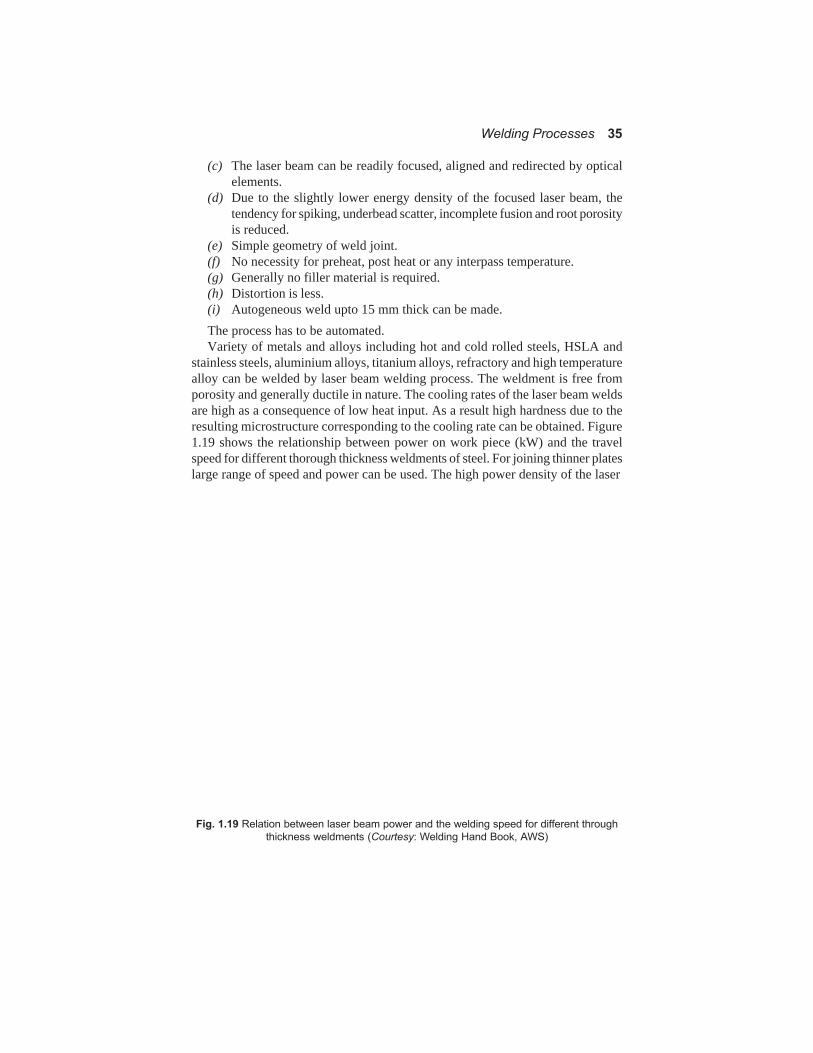
Welding Processes 35
(c) The laser beam can be readily focused, aligned and redirected by opticalelements.
(d) Due to the slightly lower energy density of the focused laser beam, thetendency for spiking, underbead scatter, incomplete fusion and root porosityis reduced.
(e) Simple geometry of weld joint.(f) No necessity for preheat, post heat or any interpass temperature.(g) Generally no filler material is required.(h) Distortion is less.(i) Autogeneous weld upto 15 mm thick can be made.The process has to be automated.Variety of metals and alloys including hot and cold rolled steels, HSLA and
stainless steels, aluminium alloys, titanium alloys, refractory and high temperaturealloy can be welded by laser beam welding process. The weldment is free fromporosity and generally ductile in nature. The cooling rates of the laser beam weldsare high as a consequence of low heat input. As a result high hardness due to theresulting microstructure corresponding to the cooling rate can be obtained. Figure1.19 shows the relationship between power on work piece (kW) and the travelspeed for different thorough thickness weldments of steel. For joining thinner plateslarge range of speed and power can be used. The high power density of the laser
Fig. 1.19 Relation between laser beam power and the welding speed for different through
thickness weldments (Courtesy: Welding Hand Book, AWS)
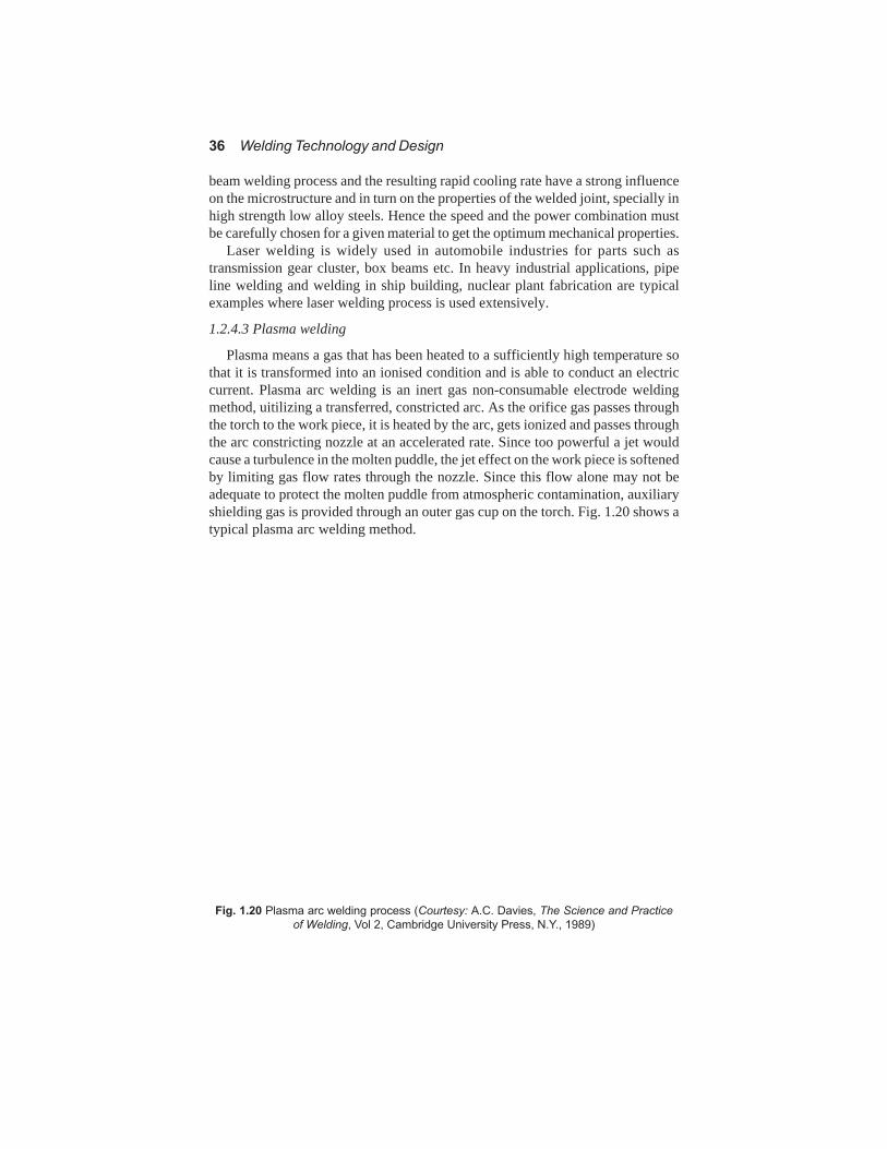
36 Welding Technology and Design
beam welding process and the resulting rapid cooling rate have a strong influenceon the microstructure and in turn on the properties of the welded joint, specially inhigh strength low alloy steels. Hence the speed and the power combination mustbe carefully chosen for a given material to get the optimum mechanical properties.
Laser welding is widely used in automobile industries for parts such astransmission gear cluster, box beams etc. In heavy industrial applications, pipeline welding and welding in ship building, nuclear plant fabrication are typicalexamples where laser welding process is used extensively.
1.2.4.3 Plasma welding
Plasma means a gas that has been heated to a sufficiently high temperature sothat it is transformed into an ionised condition and is able to conduct an electriccurrent. Plasma arc welding is an inert gas non-consumable electrode weldingmethod, uitilizing a transferred, constricted arc. As the orifice gas passes throughthe torch to the work piece, it is heated by the arc, gets ionized and passes throughthe arc constricting nozzle at an accelerated rate. Since too powerful a jet wouldcause a turbulence in the molten puddle, the jet effect on the work piece is softenedby limiting gas flow rates through the nozzle. Since this flow alone may not beadequate to protect the molten puddle from atmospheric contamination, auxiliaryshielding gas is provided through an outer gas cup on the torch. Fig. 1.20 shows atypical plasma arc welding method.
Fig. 1.20 Plasma arc welding process (Courtesy: A.C. Davies, The Science and Practice
of Welding, Vol 2, Cambridge University Press, N.Y., 1989)

Welding Processes 37
Plasma arc welding gives rise to what is known as keyhole effect whenperforming square butt joints in the thickness range of 2 to 6 mm. A keyhole isformed at the leading edge of the weld metal, where the forces of the plasma jetdisplace the molten metal to permit the arc to pass completely through the workpiece. This keyhole is an indication of complete penetration. In the key holetechnique, the molten pool is prevented from spilling by its surface tension. So nobacking is required for support. When a filler metal is required it is added to theleading edge of the pool formed by the keyhole. The molten metal flowing aroundthe keyhole forms a reinforced weld bead. Square butt joints upto 6 mm thick canbe welded in a single pass by this method.
For heavier plates which require multi-pass welding partial beveling is doneand the root pass of the largest size is deposited with the keyhole technique withoutusing filler wire. The rest of the passes are then carried out with normal melt-intechnique with filler wire addition. PAW process is limited to around 25 mm thickplates. Continuously formed stainless steel tubes are welded by plasma arc weldingprocess without filler metal. This process has high rate of welding particularly forthick tubes. The welding speed is approximately twice that of gas tungsten arcwelding for the same tube thickness.
Constricting orifice gives the stability of the plasma jet and increases itseffectiveness. The plasma arc is columnar in nature due to the constriction providedby the nozzle. So this arc is less sensitive to the arc length variation, as comparedto TIG. The area of heat input and intensity is almost constant. There are two typesof plasma arc welding. (a) transferred arc and (b) non-transferred arc. Thetransferred arc is formed between the electrode and the work piece. The non-transferred arc is formed between the electrode and the nozzle. The transferred arcimparts greater energy to the work piece than the non-transferred arc and producesheat both from the anode spot on the work piece and plasma stream. The transferredarc generally is used for welding applications. The positive lead is connected towork as well as to the orifice body for pilot arcing. The main arc strikes betweenthe electrode and the work piece. This type of connection is used for welding andcutting applications where more arc energy is to be transferred to the work piece.The non-transferred arc is used for special applications like surfacing, where lowerenergy concentration is desirable and, also used for joining of non-conductivematerials. The arc is confined between the electrode and the nozzle and the arcenergy is transferred to the work piece by the hot gas.
A mixture of argon-hydrogen (or pure argon in the case of reactive materialssuch as Zr and Ti) is used as the plasma and the shielding gases for stainless steel.For mild steel, CO2 as the auxiliary shielding gas is used. In multilayer welding forsecond and subsequent passes, helium is used. For welding a plate of say, 6 mmstainless steel, the current of 240 amps with voltage of 38 V may be required. Thewelding speed will be around 350 mm/min and the plasma gas will be 0.6 cubicmeter/hr and the shielding gas 1.4 cubic meter per hour.
The salient features of plasma arc process are:(a) narrow weld beads and HAZ(b) greater penetration and less distortion(c) less heating of surrounding parent metal and less current required than
TIG.

38 Welding Technology and Design
(d) less arc wandering.PAW process as compared to TIG process has the following advantages:(a) greater concentration of energy(b) improved arc stability at low currents(c) higher heat content(d) higher velocity of plasma(e) less sensitivity to variations of arc length(f) solid backing is avoided by adopting keyhole technique(g) no tungsten contamination.In normal TIG, the arc is of conical shape and so the area of heat input to the
work piece varies as the square of the arc length. Thus in TIG, a slight variation ofarc length will cause appreciable change in unit area heat transfer rate. But theplasma jet is cylindrical and so changes of arc length have no effect on the area ofheat input and the arc intensity. In normal TIG, the arc plasma spreads over a largearea of the work piece and the arc is easily deflected by weak magnetic fields. Inplasma process, the arc is stiff and very little affected by magnetic fields. Theconstriction of the arc in PAW results in higher plasma temperature and arc power.
However, in PAW(a) equipment cost is high(b) life of constricting nozzle is short(c) consumption of inert gas is increased.A comparison of the different energy processes is of welding with tungsten
inert gas welding is shown in Table 1.5.
1.2.5 Special methods
1.2.5.1 Explosive welding (EW)
Explosive welding is a process based on the controlled application of enormouspower generated by detonating explosives. The surfaces of the parts to be joinedmust be clean without contamination of oxides etc. These clean surfaces are pressedat pressure of the order of million kg/sqcm generated by the explosive. Combinationof dissimilar metals-aluminium to steel or titanium to steel - can be readily obtainedby this process.
Metals which are too brittle to withstand the impact of explosion cannot bewelded by this process. EW is a well suited process for cladding application.Thereis no upper limit for the thickness of the backer plate. EW can also be used forcladding the inner or outer surfaces of right cylinders.
The principle of operation is schematically shown for pipe welding in Fig. 1.21.The prime metal (external pipe) is oriented to the backer plate (internal pipe) witha small air gap, maintained by support metallic inserts. The backer plate rests onthe anvil. The explosive in plastic liquid or granular form is placed uniformly overthe prime metal and a moderating layer of polythene, water or rubber may beplaced in between the explosive and the prime plate. This protects the surface ofthe prime plate from the explosion effects. The explosion is initiated by means ofa detonator attached to it. Once the detonator is ignited, the wave front progressesforward and welds the prime plate with the backer.

Welding Processes 39
Table 1.5 Comparison of different parameters of energy welding processes and TIG
welding (plate thickness 6 mm)
Parameter Laser TIG Plasma EB
Power absorbed 4 kW 2kW 4kW 5kWby work piece.Total power used 50kW 3kW 6kW 6kW
Traverse speed 16 mm/s 2 mm/s 5.7 mm/s 40 mm/sPositional welding yes; but requires serious serious yes; but requires
optics to move penetration penetration mechanisms to
the beam move the gun
Distortion
axial minimum significant significant minimumshrinkage small yes yes minimumangular minimum yes, in yes, in parallel
V- V- sidenessshaped weld shaped
Surface profile very fine underside weld under ruffleddefects flow lines protrusion side swarf on
held in by protrusion back
surface held in by facetension surface
tension
Special safety interlock normal light normal light vacuumrequirements against screening screening chambers, X-rayfor process misplaced beam screening
reflection
End defect slight surface smooth slight surface slight surface
Start protrusion protrustion protrusion
finish smooth -do- -do- -do-
Fig. 1.21 Explosive welding parameters

40 Welding Technology and Design
The important variables of the process are(a) collision velocity and angle(b) mechanical properties of the metals tobe welded.The detonating velocity of the explosive in combination with the preset angle
between the plates determines the collisional velocity. Below a certain collisionalvelocity welding will not occur. For welding to occur, the collisional velocityshould be nearly equal to the sonic velocity of the plates.
The following Tables 1.6 and 1.7 give the metal and the sonic velocity and thedetonating parameters of different explosives.
There is a maximum collision angle above which no welding will occurregardless of collision velocity. In parallel plates cladding, this angle is establishedby the distance between the plates called stand-off distance. In the case of anglecladding the preset angle and the stand-off will give the collision angle.
Table 1.6 Sonic velocity of different metals
Metal Sonic velocity meter/sec
Aluminium 5370
Copper 3970
Magnesium 4493
Nickel 4667
Molybdenum 5173
Titanium 4786
Zirconium 3771
Steel 4600
Table 1.7 Detonating parameters of different explosives
Explosive Detonating Detonating Detonating
temperature velocity pressure
°C m/sec kg/sq.cm.
BDX 5450 8400 263,500
Nitropenta 5400 8300 232,000
Tetryl 4440 7800 204,000
Pertit 3900 7300 186,000
TNT Dynamite 3900 6900 158,000
Dynamite 3900 6000 107,000
When the explosion occurs and the pressure on the prime plate builds up, jettingtakes place at the collision point and brings together the two materials under highpressure and extreme plastic deformation. The original surface layer will be sweptin the jet. Thus a direct metal to metal contact is achieved and a weld results.
The bond obtained can be(a) straight direct metal to metal bond(b) wavy bond(c) straight but with a continuous layer between the plates.The type of bond depends on the collision velocity. Normally a wavy type of
bond represents a good defect free welding. EW is used in chemical processequipments to clad corrosion and erosion resistant thin materials to the inner surfaceof the pressure vessels In the coin industry, cupro-nickel is cladded on thick copper

Welding Processes 41
and the the billets are rolled. The cladding is done by explosive welding. Dissimilarmetal welds can be easily made by explosive welding method. Such welding processis commonly used is electrical and cryogenic applications.
Pipes can be welded by explosive welding process with lapped joint throughthe simultaneous initiation of external and internal explosive charges as indicatedin Fig. 1.21. The process can be easily applied under pipe line constructionconditions. The charges progressively denote from the apex outwards to the openend of the angular gap established by the overlapping or bell and spigotconfiguration. The intense pressure generated at the point of collision, incombination with the angular collision geometry, causes severe flow of the surfacelayer of the pipes and the formation of a jet. The jet—a mixture of the two surfacelayers and their contaminants—is expelled from the collision zone leavinguncontaminated metal surface in intimate contact for the formation of a metallurgicalor solid phase bond.
Another method of joining two pipes by explosive method is based on an innerring welding. A backing outer ring is placed outside the joint to take up thedetonating
Fig. 1.22 Explosive welding of two pipes with inner ring.
force. The inner ring along with the explosive is placed at the junction of the twopipes as indicated in Fig. 1.22. When the explosive detonates, the inner ring expandsand gets welded on to the inner surfaces of the two pipes. The entire force is takencare of by the back outer ring. By suitable dimensioning and controlled deformation,the inner bore diameter can be properly adjusted to suit the pipes. As all the

42 Welding Technology and Design
explosions are inside the pipe, the noise and environmental problems will be easierto solve.
Fig. 1.23 Friction welding process
1.2.5.2 Friction welding
Friction between the two welding faces is used to create heat to the extent thatthe material at the two surfaces become plastic. Welding is effected by applyingaxial force. A schematic diagram of the friction welding process is shown in Fig.1.23.
The friction welding process is divided into two distinct modes:(a) conventional drive friction welding, and(b) inertia weldingIn the conventional drive friction welding, the pieces are axially aligned. One
component is rotated at a constant speed by a direct drive while the other is movedinto contact with the former under axial pressure. Sufficient time is allowed forheat generation, so that the interfacial temperature will make the material plasticand permit the components to be forged together. At this stage the rotation israpidly stopped while the pressure is still maintained to consolidate the joint.
Though the basic principle is the same, in the inertia welding kinetic energyfrom a rotating flywheel system is used to heat the faces of components to bewelded. One component will be attached to the flywheel rotating at high speed.The other component will be brought to face the first, so that friction between thetwo will generate heat. The flywheel energy will be utilized to obtain a good bondbetween the components.
The principal variables in this process are the relative velocity, heating andforging pressure and the duration of heating. The secondary factors are pressurebuild up during heating and forging, deceleration during braking and the propertiesof the material being welded. Peripheral speeds in the range of 75 to 105 metersper minute appear to give satisfactory welds. Too high a speed may result in awide HAZ. Lower speeds will not be able to generate sufficient heat and raise thetemperature upto the required level. The forging pressure depends on the hot

Welding Processes 43
strength of the alloy being welded. The pressure chosen must be sufficient to weldthe surfaces.
Duration of the heating time depends on rotational speed, friction and thepressure. Heating time determines the heat input. Steels of all varieties, stainlesssteels, copper and its alloy can be easily welded by friction welding process.
In inertia welding the initial peripheral velocity of the rotating work piece,axial pressure and the flywheel size are the main factors to be considered for goodwelding. The peripheral velocity must be above a minimum e.g., for mild steel it is1.5 meter/sec. The axial pressure influences the heating. As a thumb rule, the valueof the thrust pressure can be chosen as about 25 per cent of the room temperatureyield strength of the material being welded. The flywheel size and the surfacespeed of the material control the energy required for the inertia welding process.The power capability of the flywheel is limited only by the rate at which it can beretarded.
The peak power demand is met by the flywheel by stopping in about 0.5 sec forsteel, 0.2 sec for copper and 0.1 sec for tungsten. In addition the flywheel suppliesthe torsional forging force towards the end of the welding cycle. To keep the thermaldisturbances to a minimum, and to avoid over upsetting, welding times are usuallyreduced to a few seconds. However, the time is dependent on the material to bewelded and the size of the weldments and hence the maximum time may be up toa half a minute.
The type and shape of the joint made by friction welding are limited by the verynature of the welding process. Round-bar butt joints, tube butt joints, bar or tubetee-joints can be made in a wide range of materials. Joints between dissimilarmetals can also be made: for example, copper to steel, copper to aluminium,aluminium to steel or brass and bronze to aluminium or steel. Special steel alloywith differing properties can also be successfully welded. Welding of certain plasticsis also possible.
Special friction welding machines which provide a high degree of control overthe variables in the welding process, namely, time, surface speed and axial pressureto suit a wide range of materials are available and the welding of parts can berepeated without any defect or difficulty.
Tables 1.8 and 1.9 give the typical parametric values for frictional welding andinertia welding.
Table 1.8 Typical parameter of frictional welding
Material Diameter of Rotational Axial pressure Upset
surface mm speed rpm kg/sqmm mm
Low carbon steel 20 1500 5 - 12 5
Medium carbon steeel 10 3000 4 - 10 3
Stainless steel 10 1500 12 - 30 3
Dissimilar weld
High speed steel + 15 1500 12 - 30 6
carbon steel

44 Welding Technology and Design
Table 1.9 Typical parameters for inertia welding
Base material Peripheral Minimum Axial pressure
speed weld energy for 15 mm
meter/s kg.m./sqmm kg/sqmm
LC steel 2.5 - 5 6.6 11.2
MC steel 2.5 - 5 7.7 12.0
S.S. 3.0 - 4.5 8.2 13.8
S.S. to carbon steel 3.0 - 4.0 3.2 13.8
Radial friction welding of pipes
Radial friction welding is a one-shot welding process with great potential for thejoining of pipe lines. It operates on the principle of rotating and compressing asolid ring on two stationary pipe ends producing a solid state bond. Radial frictionwelding is essentially a forge welding process where heat is provided by relativerotary motion of the ring and the pipe. The pipes to be joined are clamped stationaryand the welding action is provided by the rotating solid ring located around thepipe ends. A simple form of the process is shown in Fig. 1.24. The rotating ring iscompressed radially and welding of the pipe ends is initiated by the heat produceddue to friction and the plastic flow of the material. After a predetermined heatingperiod, ring rotation is stopped and an increased level of compressive force isapplied to consolidate the weld. Throughout the weld sequence, the two pipes aresecurely clamped to prevent axial and rotational movement. A support mandrelcan be inserted in the bore of the pipes to prevent pipe collapse and flash metalpenetration. Experience has shown that defect free welds are readily produced incarbon-manganese steel and duplex stainless steel.
Fig. 1.24 Radial friction welding of pipes
1.2.5.3 Diffusion bonding
Diffusion bonding is a joining process which requires high temperature toenhance diffusion, but involves very little macroscopic deformation; the joint isformed without any filler metal and the microstructure and composition at theinterface are the same as those of the base metals. Pressure is applied which will

Welding Processes 45
cause local plastic and creep deformation at the temperature of operation. Bondingwill take place due to diffusion and will depend on temperature, time and thepressure applied. An interlayer foil or coating may be used to improve the bondingcharacteristics. Recrystallization and grain boundary migration at the interfacewill occur at the final stages of bonding and these processes are essential forobtaining high strength joints and to eliminate the planar boundary interface.
The pressure can be applied on the surfaces to be joined through a platten. Gaspressure can also be used to achieve the same. To preserve the clean surface thebonding can be carried out in vacuum. If gas pressure is employed for the applicationof load, then an argon gas chamber can be used. The major advantages of diffusionbonding are:
(a) Joint strength can approach that of the base metal.(b) Sintered products, dissimilar materials including metal and ceramics can
be joined by this process.(c) Bonding involves minimum deformation and distortion and hence close
dimensional control is possible.(d) In metal ceramics joints residual stresses can be reduced by multiple
interpayers.(e) Thin sheets of fine grained superplastic materials can be easily joined and
formed to any desired shape and contour by diffusion bonding.(f) Large area bonding is possible and thick and thin sections can be easily
joined. Process time is independent of area or number of components.(g) Machining cost is reduced and no flux or electrode is necessary.The important variables that will affect the bond quality are (i) surface roughness,
and (ii) surface oxide films. Stable oxide films such as Al2O3 or Cr2O3, nitride orcarbide films make solid state bonding difficult and need to be removed by spattercleaning. However, unstable oxides such as Ag2O or oxides soluble in the basemetal such as TiO2, allow good bonds to be made if the operating temperature isabove the oxides' instability temperature.
Some typical examples of diffusion bonding are presented in the following:Titanium alloys: The operating temperature is kept above 850°C so that the
surface oxide film TiO2 will dissolve in the parent metal. The environment mustbe free from oxygen and moisture. For thick sheet a pressure of 14 MPa may beapplied for bonding. Void defects in diffusion bonding joints usually originatefrom grinding or machining grooves on the surface. In inert gas environment voidscan be caused by entrapped gas. Good surface finish of the base materials andbonding in vacuum will reduce the chance of void formation. Typical joint shearstrength for Ti-6Al-4V sheet will be 575 MPa (almost the same as the parent metalstrength), for diffusion bonded joint, as compared to 10 MPa for rivetted jointsand 40 MPa for adhesive bonded joints.
Aluminium alloys : The presence of tenacious surface oxide film makesdiffusion bonding of aluminium alloys very difficult. Introduction of soft interlayersin the form of cladding coating or foil inserts enables bonds to be made with smalloverall deformation. 7475 aluminium alloy sheets can be successfully welded using5052-Al-Mg alloy as an interlayer and the operating temperature and applied
46 Welding Technology and Design
pressure as 500°C and 2.75 MPa respectively. The maximum shear strength isobtained with the bonding time of around 4 hours. The production of oxide freesurfaces on aluminium alloy can be possible by using argon-ion spatter cleaning,followed by coating by silver. Such surfaces are readily bonded above thedissociation temperature of Ag2O (=200°C).
Dissimilar metals: The need to have physical and chemical compatibilitybetween the two material to be joined, makes it necessary to have interlayers indiffusion bonding of dissimilar metals. Use of multiple layer is more common toobtain good and sound bonding. The interlayers must exhibit mutual solubilitywithout the formation of intermetallic compounds, wide temperature range forbonding (0.5 to 0.7 Tm), compatible thermal expansion, and Young's moduli.Joining of Ti alloy with stainless steel can be achieved by having interlayers madeof Ni/Cu/V combination. Thus the joint will have stainless steel/Ni/Cu/V/Ti-Al-4V interface. Such a bond made at 850°C under a pressure of 10 MPa gives atensile strength of around 400 MPa (70% of the UTS of stainless steel).
Metal matrix composites (e.g. Ti alloy with SiC fibres) are also produced bydiffusion bonding methods, similar to the dissimilar metal joining. Titanium alloycomponents joined by diffusion bonding are widely used in aerospace applications.Dissimilar metal (Ti/S.S., Ti/Al) diffusion bonded components find their applicationin cryogenic tube constructions. Al/Zr joints are used in nuclear fuel elementconstructions. Metal/ceramics joints are used in high temperature applications asin engine valves and fuel nozzles.
1.2.6 Selection of welding process
There are a number of welding processes available; however, their application isdictated by the material properties, type of weld joints, their quality required in theservice condition, cost and availability of the machine and operator's skill. Thefollowing gives a comparative study of the different processes discussed and theirapplicabliity to different materials.(a) Oxy-acetylene gas welding: This process can be used for carbon steel, copper,
aluminium, bronze welding. Sheet metal welding and small diameter pipewelding can be effectively carried out. Control of the flame is important.Plates of thickness upto 8 mm - 10 mm can be welded.Red brass and yellow brass are preferably welded by oxy-acetylene processto minimize vapourization of zinc.
(b) Shielded metal arc welding: This process is widely used. All engineeringmaterials can be welded. However, low melting and high reactive metalswill be difficult to weld. This process is easy to operate and plates ofthickness ranging from 1 mm to 25 mm can be easily welded. Preheatingwill be required in some alloy steels. Welding can be done in flat, inclined,vertical and overhead position. Edge preparations are essential in weldingthick plates.Manual metal arc welding is commonly used in the erection of structuralworks like storage tanks, bridge etc. In open breezy conditions flux coredself shielded welding is better suited. Heavier plates are usually groovewelded.

Welding Processes 47
MMA and MIG/CO2 processes are used for welding nozzles and otherattachments in pressure vessels. MMA and TIG are extensively used forwelding cupronickel (70:30 alloy) for water pipe and condenser tubes.While welding carbon and low alloy steel pipes by MMA process for steampower plants, backing rings are commonly used. However, backing ringsare rarely used for piping in oil refineries and chemical plants.
(c)Submerged arc welding: Carbon and alloy steels and copper alloys can be weldedby this process; generally applied for plate thickness above 10 mm. Bestsuited for automatic welding in boilers, pressure vessels, ship building wherehigh quality welds for larger thickness plates are required. This process isgenerally used for flat and horizontal positions. Not suitable for cast iron.With U-type of grooves, narrow gap welding can be carried out by thisprocess and, plates as thick as 300 - 400 mm can be welded. In such casesof pressure vessel cylinders and pipes made of large thick plates, automaticsubmerged arc process is preferred.
(d) Gas metal arc welding (TIG and MIG): All engineering materials except Zncan be welded. The thickness of the plates ranges from 1mm to 6mm. TIGis applied to all non-ferrous and alloy steel welding and also for root passin pipe welding. Welding equipment is more complex and costly. Difficultto weld small corners and, out-door applications are limited. MIG processin semi-automatic or fully automatic form is used for non-ferrous andstainless steel pressure vessel parts.In the manufacture of boiler units, large number of tube butt welds have tobe made with the tubes positioned at any angle from horizontal to vertical,with restricted access. In such cases automated oribital TIG welding withautomatic cold wire feed is used.Titanium alloy tubes with wall thickness 1.6 mm and below are normallywelded by TIG process without filler wire. For heavier pipes, filler metalsare used.
(e) Plasma arc welding: This process is used mainly for reactive metals. Thethickness of plates is usually upto 1.5 mmPlasma arc welding equipments are costly and, mechanised PAW isrestricted to flat and horizontal positions. Operating conditions are quitedifficult. Large amount of ultra violet and infra-red rays are emitted. ThusPAW is used for welding Ni-alloys and refractory metals for specialapplications. It is also used for refractory metal coating, alumina (Al2O3)and titania (TIO2) on graphite nozzle for rockets.
(f) Spot, Projection and Seam welding: These processes meant for sheet metals arewidely applied in automobile parts, tube manufacturing and sheet metalindustries. All engineering metals can be welded. Precautions are necessaryin the case of copper and alunium alloys which are good thermal andelectrical conductors.Flash or induction welding is used for tubular joints in boiler construction.At site, such welds are made by TIG for the root pass and MMAW forsubsequent passes.

48 Welding Technology and Design
In automotive industries, radiators are either brazed or resistance seamwelded. Upset seam welding is used for exhaust and tail pipes. The sideseams are usually spot or seam welded. Seam welding is normally limitedto sheets upto 5 mm thick.Baffles and other interior parts are spot welded in place. A typical applicationof projection welding is in the manufacture of honey comb panels.Propeller and drive shafts are commonly made from resistance weldedtubing with the end forgings arc welded by submerged arc or MIG/CO2process.
(g) Electro-slag welding: This process is for thick section welding, 50 mm andabove, of alloy steels. This is mainly used for pressure vessel parts, steelplant equipments, large shafts etc. Both ESW and SAW are best suited forthick plates; however, ESW is more specialized in its application and lessflexible compared to SAW.
(h) Electron and laser beam welding: Stainless steel, nickel base alloys, Ti and Zrand other reactive metals upto 10 to 25 mm can be welded. Specialapplications are in electronic industries, nuclear and aerospace industries.The process is rather costly.Laser welding has the ability to make tiny spot welds. So it is applied inmicroelectronic circuits. Laser beam can weld metals on silicon andgermanium.
(j) Diffusion bonding: This is widely used in the manufacture of metallic componentsfor electronic tubes.
1.3 CLASSIFICATION OF ELECTRODES
1.3.1 Electrode coating
Electrode covering has a large effect on its performance. The functions of theelectrode include the following; it
(a) provides a vapour shield to protect the molten metal from reaction with theoxygen and nitrogen of the air.
(b) provides an ionised path for conducting current from the electrode tip tothe work and for maintenance of an arc.
(c) provides flux for cleansing the metal surface of oxides and tying up anyoxides as slags that float to the top and may be removed from the finishweld.
(d) controls the weld profile, especially on fillet welds.(e) controls the melt-off rate of the electrodes(f) controls the penetration properties of the arc.(g) provides filler metal in addition to that supplied by the core wire.(h) adds alloy materials to the weld deposits where a particular chemical
composition is required.Materials used in the electrode covering for fluxing and slag formation, vary in
their abilities to clean dirty or rusty plate and provide the thickness of the resultantslag covering. These materials remove undesirable elements, and form slags that
Welding Processes 49
rise to the surface of the pool, freeze before the metal below freezes and thus aid inthe protection of the molten metal from reaction with the atmosphere. Deoxidizersin the covering serve to reduce oxides that might have been present on the work orinadventently formed by oxidation of the molten metal through imperfect shieldingor slagging. Oxides would tend to make the weld metal brittle. The most commonlyused deoxidizing agents are silicon, aluminium and manganese.
Arc stabilization is another important function of the electrode covering. WithAC current, which reverses its direction, there is tendency for the arc to “cut-off”every time the current flow is reversed. This problem is solved in the AC electrodeby incorporating potassium compounds, such as potassium titanate in the covering.Thus DC electrodes are not useable with AC currents, but AC electrodes can beused with DC current.
The electrode covering is also used for adding filler metal ingradients to theweld deposits. Thus iron powder is extensively used in electrode covering-addingiron to the weld, in addition to the iron supplied by the core wire. A small percentageof iron powder, in some E6010 electrodes, stabilizes and quiets the arc withoutloss of penetration characteristics. Iron powder added in large amount increasesthe deposition rate, increases the optimum current and, with thick covering,facilitates the use of the drag technique in welding. The electrode covering canalso be a source of alloying metals, such as manganese, nickel, chromium, andmolybdenum. When mixed with iron from the steel wire core, an alloy weld iscreated during the welding process.
There are four main types of electrode coatings on which all mild and low alloysteel electrodes are based.(a) Gas shielded (cellulosic) electrodes : These coatings developed originally
nearly 60 years ago contain over 30 per cent of organic material such asalpha flock, wood flour or other cellulose. In the arc the coating breaksdown to give a voluminous gas shield of H2, CO and CO2 which give goodprotection of the molten weld metal with consequent good weld metalproperties. These electrodes develop a strong plasma jet which givesexcellent penetration. Burning off rate of the electrode is low and the coatingconstitution leads to only a small amount of thin friable slag being formed,which makes the electrode very suitable for positional welding, includingvertical position. Direct current is necessary.
(b) Rutile electrodes : This coating contains 50 per cent titania (TiO2) as the mineralsrutile or ilmenite. This compound gives good arc stability and low operatingvoltage so that it can readily be used with alternating current. Protectionagainst contamination is effected by a gaseous atmosphere containinghydrogen, oxides of carbon nitrogen together with an acidic slag, whoseviscosity can be varied by minor mineral additions. The easily controllableslag, low spatter, medium penetration and high depostion rate make thiselectrode type ideal for general engineering. Weld appearance is also goodand uniform and mechanical properties are generally sound. However,ductility is lower than that with other coatings.

50 Welding Technology and Design
(c) Iron oxide/silicate electrodes : The coating is based on iron oxide and manganeseoxide and associated silicates. This gives very little gas shielding but avoluminous acidic slag which can result in intense slag metal reactions.Depending on other constituents of the coating, the high oxygen contentcan lead to a very low carbon weld deposit of low strength or a welldeoxidised deposit with good strength and ductility. A low operating voltagemakes the electrode suitable for a.c or d.c. The slag makes control, andtherefore position welding difficult, but gives good weld appearance witha slightly concave profile which is excellent for fillet welds and deepgrooves. Deposition rates are high, penetration good and spatter low.Although mechanical properties (strength and ductility) and soundness aregood, the high oxygen content of the weld metal gives low notch ductility.Additionally, the acid slags cannot cope with high sulphur contents whichlead to weld metal cracking.
(d) Basic electrodes : This type, also known as low hydrogen, lime-ferritic orlime-fluorspar electrodes, has a complex coating containing a highproportion of limestone (CaCo3) and Fluorspar (CaF2). Clays, asbestos andother minerals with combined water are kept to a minimum to ensure verylow hydrogen contents in the weld deposit. For this reason basic electrodesare also baked at a higher temperature than other types and are stored underdry conditions.Protection against contamination is by CO2-CO gas yield (with no H2) anda fluid basic (or semi basic) slag which allows good deoxidation of themetal which has low oxygen content. Mechanical properties includingductility and notch toughness are superior to other types, soundness isexcellent and the deposit has a high resistance to hot and cold crackingwhich is very good for welding higher strength steels (most alloy electrodeshave basic coatings). Basic electrodes are also less sensitive to plate qualitythan other types and they are used for high carbon or high sulphur containingsteels.The arc voltage of basic electrodes is fairly high, and most electrodes requiredirect current electrode positive. But the addition of potassium salts to thecoating leads to potassium ions in the arc atmosphere and allows the use ofalternating current. It is necessary to maintain a short arc length. The slagis fluid and gives the weld bead a convex to flat profile which can lead todeslagging problems. These electrodes give medium speed of deposition,moderate penetration and good bead appearance. They are generally moredifficult to use than rutile electrode and require short arc lengths and carein weaving, stopping and starting, if porosity and slag inclusions are to beavoided. Dampness in the coating must be avoided.
Table 1.10 gives the comparision of the four electrodes. The differences areonly marginal.
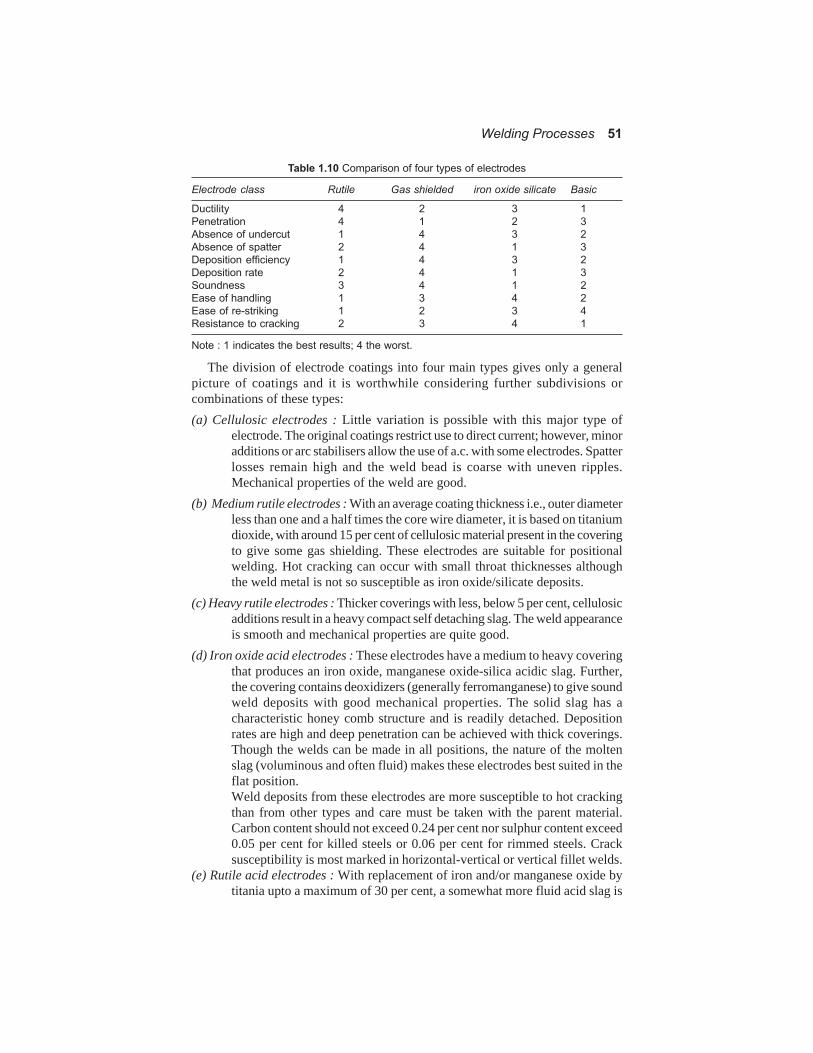
Welding Processes 51
Table 1.10 Comparison of four types of electrodes
Electrode class Rutile Gas shielded iron oxide silicate Basic
Ductility 4 2 3 1
Penetration 4 1 2 3
Absence of undercut 1 4 3 2
Absence of spatter 2 4 1 3
Deposition efficiency 1 4 3 2
Deposition rate 2 4 1 3
Soundness 3 4 1 2
Ease of handling 1 3 4 2
Ease of re-striking 1 2 3 4
Resistance to cracking 2 3 4 1
Note : 1 indicates the best results; 4 the worst.
The division of electrode coatings into four main types gives only a generalpicture of coatings and it is worthwhile considering further subdivisions orcombinations of these types:(a) Cellulosic electrodes : Little variation is possible with this major type of
electrode. The original coatings restrict use to direct current; however, minoradditions or arc stabilisers allow the use of a.c. with some electrodes. Spatterlosses remain high and the weld bead is coarse with uneven ripples.Mechanical properties of the weld are good.
(b) Medium rutile electrodes : With an average coating thickness i.e., outer diameterless than one and a half times the core wire diameter, it is based on titaniumdioxide, with around 15 per cent of cellulosic material present in the coveringto give some gas shielding. These electrodes are suitable for positionalwelding. Hot cracking can occur with small throat thicknesses althoughthe weld metal is not so susceptible as iron oxide/silicate deposits.
(c) Heavy rutile electrodes : Thicker coverings with less, below 5 per cent, cellulosicadditions result in a heavy compact self detaching slag. The weld appearanceis smooth and mechanical properties are quite good.
(d) Iron oxide acid electrodes : These electrodes have a medium to heavy coveringthat produces an iron oxide, manganese oxide-silica acidic slag. Further,the covering contains deoxidizers (generally ferromanganese) to give soundweld deposits with good mechanical properties. The solid slag has acharacteristic honey comb structure and is readily detached. Depositionrates are high and deep penetration can be achieved with thick coverings.Though the welds can be made in all positions, the nature of the moltenslag (voluminous and often fluid) makes these electrodes best suited in theflat position.Weld deposits from these electrodes are more susceptible to hot crackingthan from other types and care must be taken with the parent material.Carbon content should not exceed 0.24 per cent nor sulphur content exceed0.05 per cent for killed steels or 0.06 per cent for rimmed steels. Cracksusceptibility is most marked in horizontal-vertical or vertical fillet welds.
(e) Rutile acid electrodes : With replacement of iron and/or manganese oxide bytitania upto a maximum of 30 per cent, a somewhat more fluid acid slag is
52 Welding Technology and Design
produced. Mechanical properties and weld soundness are similar to ironacid electrodes.
(f) Oxidising electrodes : A thick covering based on iron oxide and possiblemanganese oxide without deoxidants produces an oxidising slag whichgives a weld deposit with very low carbon and manganese contents andlow strength. Penetration is low and molten weld metal fluid, restrictinguse to horizontal/vertical or flat fillet welds. The slag is heavy, compactand self detaching and gives excellent weld appearance.
(g) Basic electrodes : These electrodes have thick coverings containing considerableamount of basic carbonates (generally calcium or magnesium) and calciumfluoride, which give CO2 gas shielding and an active basic or semi-basicslag. Deoxidation is generally effected by ferro-silicon and ferro manganese.The deposited weld metal is low in oxygen, hydrogen and nitrogen, retainsalloying additions and has excellent mechanical properties, particularlyductility and toughness. A medium quantity of dense slag forms on theweld giving a reasonably good appearance. Slag inclusions are rare.The coatings are often hydroscopic and must be stored under warm dryconditions to prevent moisture. Otherwise hydrogen in the weld metal canlead to porosity, fissuring and underbead cracking in susceptible steels.Moisture content should not exceed 0.6 per cent.The high ductility and low hydrogen content of the weld deposits lead toexcellent resistance to hot and cold cracking and basic electrodes areparticularly suitable for welding heavy or highly restrained structures.
(h) Iron powder electrodes : Iron powder can be added to all types of electrodecoverings; so it is not strictly a single type.
The main advantages of the addition of iron powder are :* it allows nearly twice the deposition rate;* the iron powder is recovered in the weld deposit so that a specified
electrode length will give a longer arcing time and a large bead.Iron powder also reduces the operating voltage; this can be an advantage,and for example, it allows cellulosic electrodes to be used with alternatingcurrent; however, 50 per cent iron powder in the coating reduces operation.Iron powder also increases slag fluidity which leads to manipulationdifficulties for positional welding. However, electrode coverings are oftenslightly conducting and this allows ‘touch’ welding in the flat position. Toget high deposition rates, particularly at the lower operating voltages. theseelectrodes use high current which can lead to a decrease in weld metalductility. Ductility improves after a post weld tempering or stress relievingheat treatment.A recent development has been the introduction of low hydrogen rutileiron powder electrodes which offer an electrode that is easy to use in theflat position and gives a low hydrogen content in the weld deposit. There issome indication that certain of these electrodes can give porosity inpositional welds and require a high level of operator skill for positionwelding.
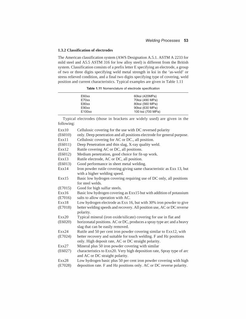
Welding Processes 53
1.3.2 Classification of electrodes
The American classification system (AWS Designation A.5.1. ASTM A 2233 formild steel and A5.5 ASTM 316 for low alloy steel) is different from the Britishsystem. Classification consists of a prefix letter E specifying an electrode, a groupof two or three digits specifying weld metal strength in ksi in the ‘as-weld’ orstress relieved condition, and a final two digits specifying type of covering, weldposition and current characteristics. Typical examples are given in Table 1.11
Table 1.11 Nomenclature of electrode specification
E60xx 60ksi (420MPa)
E70xx 70ksi (490 MPa)
E80xx 80ksi (560 MPa)
E90xx 90ksi (630 MPa)
E100xx 100 ksi (700 MPa)
Typical electrodes (those in brackets are widely used) are given in thefollowing:Exx10 Cellulosic covering for the use with DC reversed polarity(E6010) only. Deep penetration and all positions electrode for general purpose.Exx11 Cellulosic covering for AC or DC., all position.(E6011) Deep Penetration and thin slag, X-ray quality weld.Exx12 Rutile covering AC or DC, all positions.(E6012) Medium penetration, good choice for fit-up work.Exx13 Rutile electrode, AC or DC, all position.(E6013) Good performance in sheet metal welding.Exx14 Iron powder rutile covering giving same characteristic as Exx 13, but
with a higher welding speed.Exx15 Basic low hydrogen covering requiring use of DC only, all positions
for steel welds.(E7015) Good for high sulfur steels.Exx16 Basic low hydrogen covering as Exx15 but with addition of potassium(E7016) salts to allow operation with AC.Exx18 Low hydrogen electrode as Exx 16, but with 30% iron powder to give(E7018) better welding speeds and recovery. All position use, AC or DC reverse
polarity.Exx20 Typical mineral (iron oxide/silicate) covering for use in flat and(E6020) horizonatal positions. AC or DC, produces a spray type arc and a heavy
slag that can be easily removed.Exx24 Rutile and 50 per cent iron powder covering similar to Exx12, with(E7024) better recovery and suitable for touch welding. F and Hz positions
only. High deposit rate, AC or DC straight polarity.Exx27 Mineral plus 50 iron powder covering with similar(E6027) characteristics to Exx20. Very high deposition rate, Spray type of arc
and AC or DC straight polarity.Exx28 Low hydrogen basic plus 50 per cent iron powder covering with high(E7028) deposition rate. F and Hz positions only. AC or DC reverse polarity.

54 Welding Technology and Design
Exx30 Mineral covering similar to Exx20 but high deposition rates. F positiononly.
Note : The use of mineral or iron oxide/silicate covered electrodes is decreasing inthe USA and UK.
Several high tensile low hydrogen electrodes are classified with extra suffixese.g., Exxxx-A1-B2 etc., which indicate the chemical composition of the deposit,and gas content of manual metal arc weld deposits.
AWS-specification A5.5-69 prescribes the chemical requirements for low alloyshielded metal arc weld metal. Classification is similar to that the mild steels coveredelectrodes with the addition of a suffix to indicate the alloy constituents of thedeposited weld metal. e.g., E7010-A1 or E 8016-B1. A1 for carbon molybdenumsteel and B1 for chromium-molybdenum steels.Electrodes - IS and AWS classifications and codes.
In the following are given some of the IS and AWS specifications for electrodes.For details the reader is advised to consult the specifications which cover thechemical compositions, mechanical properties, impact strength and otherrequirements.
IS 814 - 1991 Covered electrodes for manual metal arc welding of carbon andcarbon manganese steels.
This standard is primarily concerned with the mechanical properties of the weldmetal and no limits have been specified on the chemical composition of the weldmetal.
For weld metals with tensile strength higher than 610 MPa reference can bemade to IS 1395-1982 “Low and medium alloy steel covered electrodes forMMAW”.
The classification of electrode is given by letter and numericals as give below :Ex xxxxE R 4211The first letter “E” indicates a covered electrode for MMAW, manufactured by
extrusion process,The second letter “R” indicates type of covering e.g., R = Rutile, A = Acid, B =
Basic, C = Cellulosic, RR = Rutile heavy coated, S = any other type not mentionedhere.
The first numerical “4” indicates strength (UTS = 410-510 MPa) in combinationwith the yield strength of the weld metal deposit YS = 330 MPa.
The second numerical digit indicates percentage elongation in combination withthe impact value of the weld metal deposited. Thus “2” means 22 per cent minimumelongation with impact 47 J at zero °C.
The third digit “1” shows welding position in which the electrode may be used.“I” means all positions.
2 = all position except vertical3 = flat butt weld horizontal/vertical fillet weld4 = flat butt and fillet weld5 = vertical down and flat butt6 = any position not mentioned here.

Welding Processes 55
The fourth digit indicates the current condition in which the electrode it to beused. Other IS and AWS standards are:IS 815 1967 Classification and coding of covered electrodes for metal
arc welding of structural steel.IS 1387 1967 General requirement relating to supply of covered
electrodes for metal arc welding.IS 1395 1982 Low and medium alloy steel covered electrodes for
MMAW.IS 5206 1969 Specification for corrosion resisting chromium nickel steel
covered electrodes.IS 5511 1969 Covered electrodes for MMAW of cast ironIS 5898 Copper and copper alloy bare solid welding rods and
electrodes.IS 6419 1971 Welding rods and bare electrodes for gas shielded arc
welding of structural steels.IS 7280 1974 Specification for bare wire electrodes for SAW of
structural steels.IS 8666 1977 Specification for copper and copper alloy covered
electrodes for MMAW.IS 9595 Recommendations for metal arc welding of carbon and
carbon -Mn steels.AWS A 5.1 1981 Specification for carbon steel covered arc welding
electrodes.AWS A 5.3 1988 Aluminium and aluminium alloy electrodesAWS A 5.4 1981 Corrosion resistant chromium and Cr-Ni steel covered
welding electrodes.AWS A 5.5 1981 Low alloy steel covered arc welding electrodesAWS A 5.6 1984 Covered copper and alloy arc welding electrodes.AWS A 5.7 1984 Copper and copper alloy filler rods suitable for TIG,
Plasma, and MIG welding processAWS A 5.9 1981 Corrosion resisting Cr and Ni-Cr steel filler wires suitable
for TIG, MIG, and SAW processes.AWSA 5.10 1988 Aluminium and aluminium filler wires suitable for
oxyacetylene, TIG, Plasma arc and MIG processes.AWSA 5.11 1990 Nickel and nickel alloy covered welding electrodes.AWS A 5.12 1980 Tungsten arc welding electrodes.AWS A 5.13 1980 Solid surfacing welding rods and electrodes.AWS A 5.14 1989 Nickel and nickel alloy bare welding rods and electrodes.AWSA 5.15 1990 Welding rods and covered electrodes for cast iron.AWSA 5.17 1980 Carbon steel electrodes and fluxes for submerged arc
welding.AWS A 5.16 1990 Titanium and Titanium alloy filler wires.AWS A 5.18 1979 Carbon steel filler metals for TIG, Plasma arc and MIG/
CO2 processes.AWS A 5.19 1980 Magnesium alloy filler wires.AWS A 5.20 1979 Carbon steel electrodes for flux-cored arc welding.

56 Welding Technology and Design
AWS A 5.21 1980 Composite surfacing welding rods and electrodesAWS A 5.22 1980 Flux cored Cr and Cr-Ni steel electrodesAWS A 5.23 1990 Low alloy steel electrodes and fluxes for submerged arc
welding.AWS A 5.24 1990 Zr and Zr alloy filler metal.AWS A 5.25 1991 Flux wire combinations used for electroslag welding of
carbon and high strength low alloy steels.AWS A 5.26 1978 Consumables used for electro-slag welding of carbon and
high strength alloy steels.AWS A 5.28 1979 Bare solid wire of low alloy steel for use with TIG, MIG
and PAW processes.AWS A 29 1980 Low alloy steel electrodes for flux covered arc welding.
Matching electrodes must be used for alloy steels and stainless steels. Forcorrosion resistant base metals the electrode must also be corrosion resistant.Chromium-nickel steel electrodes are classified on the basis of chemicalcomposition of the filler metal. AWS - A5.5--69 and AWS A5.5-69 specificationsgive the composition for stainless steel electrodes.
Hydrogen, oxygen and nitrogen can be present in mild and low alloy steel welddeposits; all are detrimental even in small amounts.
Hydrogen lowers the ductility and notch ductility of weld deposits. It is believedto cause fissuring (Micro-cracking) in non-hardenable weld deposits and cold(underbead) cracking in the heat affected zones of hardenable steels. It can alsocause porosity. Hydrogen is considered to affect notch ductility and cracking inamounts above 0.0087 per cent.
Oxygen can lead to poor notch impact performance possibly by acting as acatalyst for precipitation reactions such as strain ageing. In larger amounts it canreact with carbon to give carbon-monoxide and hence porosity.
Nitrogen is believed to contribute to weld metal fissuring and in larger amountsit leads to reduced ductility and the formation of hard needles of iron nitride. It canhave a deleterious influence of creep behaviour, and in larger amounts causeporosity.
Basic covered electrodes give weld deposits low in hydrogen, oxygen andnitrogen. Cellulosic electrodes also give deposits with good mechanical propertiesand weld metal low in oxygen and nitrogen.
Some electrodes are compounded to deposit weld metal that solidifies rapidlyafter being melted by the arc, and are thus used specifically for welding in thevertical and overhead positions. They are known as Fast Freeze Electrodes.Commonly used Fast Freeze Electrodes in the welding of steel are E 6010, E 6011,E 7010-A and E 7010-G. The deposition rates are not very high with theseelectrodes. These electrodes provide deep penetration and maxium admixture. Slagformation is light and the arc is easy to control.
There are electrodes which are compounded to deposit metal rapidly in the heatof the arc, and are thus well suited to high speed welding on horizontal surface.These electrodes are known as Fast-Fill Electrodes. The weld metal solidifiessomewhat slowly and so these electrodes are not suitable for out-of-position

Welding Processes 57
welding. The arc penetration is shallow with minimum admixture. The bead issmooth, free of ripples. Spatter is negligible and slag formation is heavy; but itpeels off easily. The commonly used Fast-Fill Electrodes in the welding of steelare E 7024, E 6027, and E 7020-A1.
Some electrodes known as Fill-Freeze Electrodes, provide a compromisebetween Fast Freeze and Fast-Fill characteristics and thus give a medium depositionrate and penetration. The commonly used Fill-Freeze electrodes are E 6012, E6013 and E 7014.
Conventional electrodes may not be suitable for high quality welds which shouldnot have any defects. In such cases low hydrogen electrodes are used. Typicalexamples are E 7018 and E 7028. These electrodes give :
(a) X-ray quality welds requiring high mechanical properties.(b) Crack resistant welds in medium or high carbon steels; welds that resist
hot-short cracking in phosphorus steels and welds that minimise porosityin sulfur bearing steels.
(c) Welds in thick sections or in restrained joints in mild and alloy steels whereshrinkage stresses may promote weld cracking.
(d) Welds in alloy steels with strength of 500 MPa.(e) Multipass, vertical and overhead welds in mild steels.Low hydrogen electrodes must be used in dry condition, if they are to give
good result.Fluxes : Fluxes are classified on the basis of the mechanical property of the welddeposit made with a particular electrode. The classification designation given toflux consists of a prefix “F”, indicating a flux, followed by two digit numbersrepresentative of tensile strength and impact requirements for test welds made inaccordance with the specification. This is followed by a set of numberscorresponding to the classification of the electrode used with the flux.
Flux cored electrodes are tubular wire containing within it the flux with all theingradients for shielding the arc and weld pool, fluxing, deoxidizing andconditioning the molten metal. Specifications for flux cored arc welding electrodesare given in AWS A5.20-69 code.
1.3.3 Selection of electrodes
The selection of electrodes for any particular job has always been a compromisebetween the requirements of weld quality and the overall cost of fabrication.
Where quality is important it is necessary to select an electrode type which willgive the appropriate weld metal properties. However, the skill of the operators andconditions of electrode storage and usage must also be considered. In many casesit may be preferable to sacrifice the maximum quality to ensure that sound defect-free welds can be obtained under prevailing conditions of fabrication. Once therequired quality has been defined it is possible to select the electrode type andmake which will give the lowest fabrication cost or highest production rate.
Trends in electrode selections have been apparent for many years. For the highestquality in mild and low alloy steel deposits, basic electrodes are selected. If theparent plate quality is dubious or unknown, basic electrodes are again used. The

58 Welding Technology and Design
use of iron powder basic coatings can help the ease of the use and deposition ratealthough it may prevent positional weldings.
Aluminium and aluminium alloy welding rods and bare electrodes are made inaccordance with AWS A5.10.69 specifications. The filler metals are classified onthe basis of their chemical composition as manufactured and their useability. TypesER 5356, ER 4043 and ER 5183 can be used for large variety of weldingapplications.
Some typical metal arc welding electrodes for welding alloy steels are given inTable 1.12.
Table 1.12 Electrodes and their uses
1. Mild steel heavy dury electrodes
Rutile or basic coated for medium and heavy duty fabrications. The latter is suitable forcarbon and alloy steels, mild steel, high strength steels under restraint and for root runs.
2. High tensile alloy steel electrodes
Austenite rutile or basic coated; used for high strength steels including armour plates,joints between low alloy and stainless steels.
3. Structural steel electrodes
Basic coated: used for high strength structural steel and copper bearing weatheringquality steels.
4. Ductile steel electrodes for low temperature
Basic coated: used for Ni base steels, 2.5% Ni-C-Mn steels.5. Creep resistant steel electrodes
Ferritic and basic coating: can be used Cr-Mo boiler steels with pre-and post-heating.
6. Heat and corrosion resistant steel electrodesRutile or basic coating : for 19%Cr9% Ni extra low carbon stainless steels.Basic coated for Nb or Ti stabilised 18/8 stainless steels.
Rutile or basic coated for Mo bearing 18/10 Mo steels.Rutile or basic coated low carbon stainless steels electrodes for low carbon Mo bearingsteels.
Basic coated austenitic electrodes for 25% Cr-11% Ni steels and for joints in stainlesssteel cladded to mild steel.Rutile coating austenitic for 23%Cr-11% Ni heat resistant steel containing tungsten.
Basic coated 25% Cr-20% Ni (non-magnetic) for welding austenitic 20/20 steels.7. 12-14% Mn steel electrodes
Basic coating for Mn steel parts-steel excavators and mining equipments.
Tubular type electrodes for hardfacing Mn steel parts.
1.4 WELD JOINT CONSIDERATIONS
1.4.1 General procedure
For every welding job there is one procedure which will give the best includingthe cost considerations. The main factors that must be considered are :
(a) type of joint to be made, included angle, root opening and land (root face).(b) type and size of electrode.(c) type of current, polarity and amperage.(d) arc length and speed.(e) position of welds (flat, horizontal, vertical and overhead).The designer must consider problems and include them in his analysis of the
joint design.

Welding Processes 59
A root opening is used for electrode accessibility to the base of the joint. Thesmaller the angle of the bevel, the larger will be root opening to obtain good fusionat the root. Back up strips are used on larger root opening, specially when allweldings have to be carried out from one side. Spacer strips may be used speciallyin the case of double -Vee joints to prevent burn-through.
A land is provided to have additional thickness of the metal. A sharp featheredge preparation is more prone to burn through than a job with a land, especiallyif the gap is a bit too large. A land usually requires back gouging, if a perfect weldis required. A land is not recommended when welding into a back up strip, since agas pocket will be formed.
Fig. 1.25 Basic type of welded joints and welds (Courtesy: American Welding
Society, Standard Welding Symbols: A2.0-68)
60 Welding Technology and Design
1.4.2 Type of welded joints
1.4.2.1 General
The important consideration of designing a weldment is the selection of thebest type of edge preparation for the given application. During the selection thefollowing main factors must be considered.
1. Magnitude and type of loading i.e., static compression or tension, fatigue,bending, impact etc.
2. The effect of warping on cooling.3. The thickness of the material to be welded.The basic type of welded joints are: butt, tee, corner, lap and edge, as shown in
Fig. 1.25. The basic types of welds are: fillet, square, bevelgroove, J-groove andU-groove. The type of joints does not affect the weld. The definition of a weldedjoint must include description of both the joint and the weld.
1.4.2.2 Groove-welds
The commonly used groove welds have a number of typical properties :(a) Single groove welds welded from one side only should not be used for
bending or fatigue loading. It may fail due to stress concentration at theweld root.
(b) Single or double groove welds which are welded from both sides candevelop full strength.
(c) If welds do not extend completely through the thickness of the membersjointed, the joint should not be used for fatigue loading.
(d) With single or double bevel type of groove, it may be more difficult toobtain sound weld.
(e) If backing strip is used during welding, it must be removed if the joint issubjected to fatigue type of loading.
1.4.2.3 Various types of groove welds
(a) Square grooves may be used with butt, corner Tee and edge joints. Completepenetration of square groove weld is obtained by welding from both sideson material upto 3 mm thick without any root opening and on materialsupto 6 mm with adequate root opening.
(b) Single Vee groove joints are suitable for materials of 6 mm to 19 mm thickwith a minimum root opening of 60 deg. Single Vee groove joints aresuitable for most loading conditions.
(c) Double Vee groove joints are applicable to butt joint for materials withthickness ranging from 12 mm to 38 mm. Control of distortion is alsoachieved by using double Vee groove joint and welding on alternate sidesof the joint and so balancing the heat input.
(d) Single Bevel groove joints include butt, Tee and corner joints. This jointmay be used for thickness between 6 mm to 19 mm. However, the narrowincluded angle (35 to 45 deg.) of the bevel groove joint makes it one of theleast desirable types of joint.
(e) Double Bevel groove joint may be used for thickness upto 38 mm.

Welding Processes 61
Fig. 1.26. Different types of edge preparation
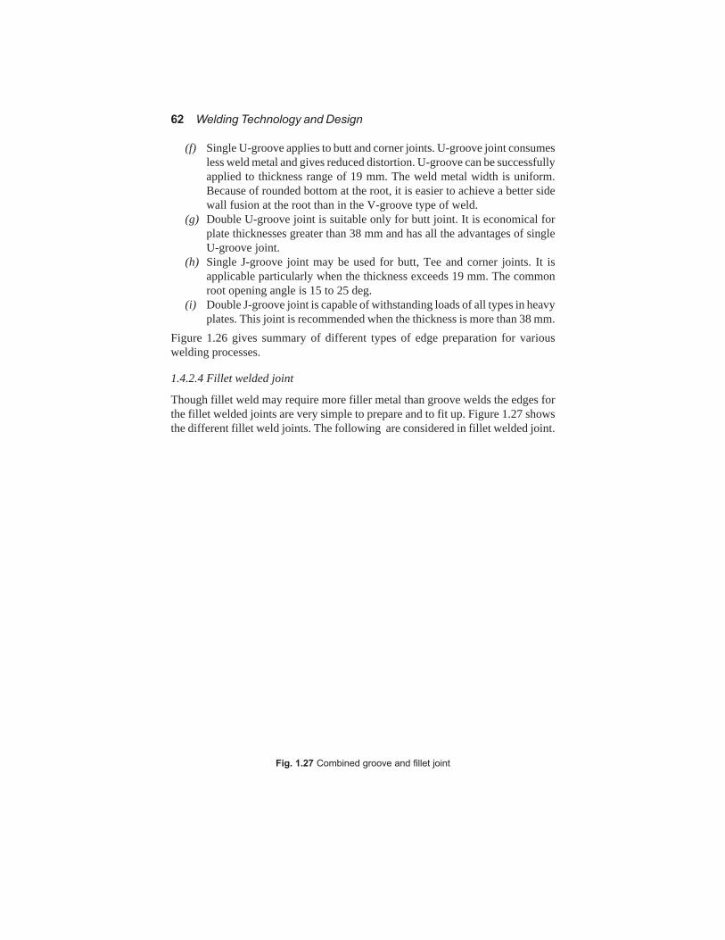
62 Welding Technology and Design
(f) Single U-groove applies to butt and corner joints. U-groove joint consumesless weld metal and gives reduced distortion. U-groove can be successfullyapplied to thickness range of 19 mm. The weld metal width is uniform.Because of rounded bottom at the root, it is easier to achieve a better sidewall fusion at the root than in the V-groove type of weld.
(g) Double U-groove joint is suitable only for butt joint. It is economical forplate thicknesses greater than 38 mm and has all the advantages of singleU-groove joint.
(h) Single J-groove joint may be used for butt, Tee and corner joints. It isapplicable particularly when the thickness exceeds 19 mm. The commonroot opening angle is 15 to 25 deg.
(i) Double J-groove joint is capable of withstanding loads of all types in heavyplates. This joint is recommended when the thickness is more than 38 mm.
Figure 1.26 gives summary of different types of edge preparation for variouswelding processes.
1.4.2.4 Fillet welded joint
Though fillet weld may require more filler metal than groove welds the edges forthe fillet welded joints are very simple to prepare and to fit up. Figure 1.27 showsthe different fillet weld joints. The following are considered in fillet welded joint.
Fig. 1.27 Combined groove and fillet joint

Welding Processes 63
(a) Single fillet welded joint is employed in Lap, Tee and Corner joints. Thestrength of these joint depends on the size of the fillet. If loading is notsevere, these joints are suitable upto 12 mm of plate thickness. In fatigueor bending the joint will be weak.
(b) Double fillet welded joint is used for Tee, lap and corner joints. It developsfull strength of the base metal and hence can be used for fatigue type ofloading also.
(c) Combined groove and fillet joint may be used in certain applications toimprove the stress distribution within the joint, specially in Tee and cornerjoints.
1.4.2.5 Comparison of joints
In general butt joint is preferable to the single and double fillet or lap jointwhen
(a) the joint undergoes appreciable tension, bending and shock or fatiguestresses.
(b) overlapping parts would decrease thermal conductivity where this is a mostimportant factor.
(c) there is a possibility of corrosion between the overlapping structures.(d) a maximum saving in weight is desired.The main disadvantages of the butt joint are :(a) Greater cost of preparation.(b) Higher assembly cost in some of the products.(c) Lack of design flexibility in weld size.(d) Greater skill required.(e) Use of smaller electrodes or filler rods and lower currents for the root layers.(f) Greater shrinkage and higher residual stresses.
1.4.3 Welding symbols
The welding symbols denote the type of weld to be applied to a particular weldment.These symbols will indicate to the designer, draftsman and the welder the exactwelding details established for each joint or connection to satisfy all conditions ofmaterial strength and service required.
Figure 1.28 (a) shows the different weld joints and the symbols used to representthem.
Figure 1.28 (b) shows the practical application of these symbols to varioustypical joints.
The welding symbols are indicated in conjunction with an arrow connected atan angle to a reference line. This reference line is usually drawn parallel to thebottom base plate. If the weld symbol is placed below the reference line, the weldface is on the other side of the joint. If the symbol is above the reference line, theweld face is on the other side of the joint. A circle where the arrow line meets thereference line indicates that it should be a peripheral (around) weld. A numericalfigure before the symbol for a fillet weld indicates the leg length. A fork at the endof the reference line with a number in it, indicates the welding process to beemployed. For example 111 is metal arc welding with covered electrode; 121 for

64 Welding Technology and Design
Fig. 1.28 (a) Welding sysmbols

Welding Processes 65
Fig. 1.28 (b) Welding Symbols
SAW; 131 for MIG; and 141 for TIG and so on. These numerical indicators fordifferent types of welding processes have been standardized and are given inwelding societies publications.