Embed Size (px)
Citation preview

3604-4157_00Patent Pending
Welding Actuator SW44with Fanuc Pulsecoder
User Manual
TOL-O-MATIC, INCExcellence in Motion®
ELECTRIC LINEAR MOTION PRODUCTS

Information furnished is believed to be accurate and reliable. However, Tol-O-Matic assumes noresponsibility for its use or for any errors that may appear in this document. Tol-O-Matic reserves the rightto change the design or operation of the equipment described herein and any associated motion productswithout notice. Information in this document is subject to change without notice.

Contents ...................................................................................................................i
List of Figures .........................................................................................................ii
HEALTH AND SAFETY REGULATIONS .....................................................................iiiGeneral
Warning for Hot Surfaces ...............................................................................ivModifications to the Equipment ...................................................................ivRequirements regarding Personnel ...............................................................ivPacking, Transport and Unpacking ...............................................................ivRisk Area and Personnel..................................................................................iv Repair and Maintenance ................................................................................iv
1 GeneralIdentification Label ..........................................................................................1Manufacturer ....................................................................................................1Intended Use .....................................................................................................2General Operations ..........................................................................................3Storage ...............................................................................................................4
2 Functional Description ......................................................................................5Actuator .............................................................................................................5Fanuc Pulsecoder..............................................................................................6
3 Basic Installations ..............................................................................................7Installing the Weld Actuator.............................................................................7Electrical Wiring................................................................................................7Cable Routing....................................................................................................7
4 Inspection and Settings ..................................................................................... 8Inspection and Settings....................................................................................8Inspection of Mechanical Travel Limits ..........................................................8Weld Motion Profile..........................................................................................9
5 Repair and Maintenance ................................................................................. 10Pulsecoder Replacement................................................................................11
6 Appendix ........................................................................................................... 13Specifications ................................................................................................. 13Thermal Sensor Specifications ......................................................................14Connector Pinout ...........................................................................................14Troubleshooting Procedure ...........................................................................15Warranty ..........................................................................................................16
i
Contents

Figure Description Page1.1 Actuator identification label ..................................................................................11.2 Examples of welding actuator installed on weldgun unit. ......................................22.1 Exploded view of actuator .....................................................................................52.2 Exploded view of Fanuc Pulsecoder ......................................................................63.1 Cable routing for top and side mounted connectors .............................................74.1 Manual operation of welding actuator ...................................................................84.2 Weld motion profile...............................................................................................95.1 Exploded view of Fanuc Pulsecoder ....................................................................116.1 Motor Power Connections...................................................................................146.2 Pulsecoder Connections......................................................................................14
ii
List of Figures

General
Read completely through the applicable sections of the manualbefore the equipment/unit is unpacked, installed or operated.Pay careful attention to all of the dangers, warnings, cautions andnotes stated in the manual.
Serious injury to persons or damage to the equipment may resultif the information in the manual is not followed.
Items that are specifically marked DANGER!, WARNING!,CAUTION!, OR NOTE! Are arranged in a hierarchical system andhave the following meaning:
DANGER! Indicates a very hazardous situation which, if not avoided,could result in death or serious injury. This signal word is limited tothe most extreme situations.
WARNING! Indicates a potentially hazardous situation which, if notavoided, could result in death or serious injury.
CAUTION! Indicates a potentially hazardous situation which, if notavoided, this situation may result in property damage or minor ormoderate injury.
NOTE! Information that requires special attention is stated here.
!
iii
HEALTH AND SAFETY REGULATIONS

Warning for Hot Surfaces
WARNING! Normal operating temperature of weld actuator canrange from 135 degrees F (57°C) to 175 degrees F (79°C).
Modifications to the Equipment
WARNING! The manufacturer takes no responsibility whatsoeverif the equipment is modified or if the equipment is used in anyway beyond performance specifications. Unauthorizedmodifications or changes to the equipment are strictlyforbidden, and void all warranties.
Requirement regarding Personnel
NOTE! All personnel must be completely informed regarding allsafety regulations and the function of the equipment.
Packing, Transport and Unpacking
NOTE! Anchor and secure actuator in such a way as to preventdamage during transport. Also make sure the actuator is clean anddry and protected from moisture.
Risk Area and PersonnelWhen installed on a weld gun, pinch points are generated capable ofhigh damaging forces. The risk area surrounding the weld actuatormust either be enclosed or clearly marked, including display signagein accordance with all applicable national and international legalrequirements for welding actuators. The risk area must be protectedby a safety system that stops the equipment if anyone enters the riskarea. Personnel who enter the risk area must be authorized, trainedand qualified for the different tasks inside the risk area.
Repair and MaintenanceAll power and supply media must be shut OFF before any work isperformed on any equipment that is associated with the weldinggun application.
iv
HOT SURFACEDO NOTTOUCH
CAUTION

1.1 Identifi cation Label
Figure 1.1: Actuator identification label
Do not remove the identification label. Do not render it unreadable!
1.2 Manufacturer
Tol-O-Matic, Inc.3800 County Road 116Hamel, MN 55340, USA763-478-8000www.tolomatic.comemail: [email protected]
1
General 1
Date ofManufacture:
6/7/05
ActuatorModel:
SW44
Serial Num.: 555121-7
Maximum 152.4 mm
Stroke: 6.00 in.
Displacement 5 mm/rev
Ratio: 0.20 in/rev
Continuous 8.9 kN
Force: 2000 lbs
Peak 17.8 kN
Force: 4000 lbs
Max TerminalVolts:
325 Vdc
Max Current: 22 A RMS
MaximumSpeed:
333 mm/sec
FeedbackMfg/Model:
Fanuc
1.3 Intended Use
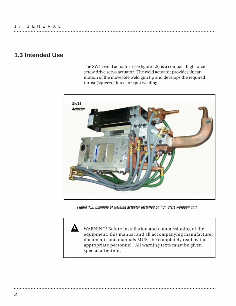
The SW44 weld actuator (see figure 1.2) is a compact high forcescrew drive servo actuator. The weld actuator provides linearmotion of the moveable weld gun tip and develops the requiredthrust (squeeze) force for spot welding.
Figure 1.2: Example of welding actuator installed on “C” Style weldgun unit.
WARNING! Before installation and commissioning of theequipment, this manual and all accompanying manufacturerdocuments and manuals MUST be completely read by theappropriate personnel. All warning texts must be givenspecial attention.
1 : G E N E R A L
2
SW44Actuator

1.4 General Operation
The SW44 actuator functions by translating the rotary motion of theintegral brushless servo motor into linear motion using a planetaryroller screw or a ball screw. The linear travel, speeds and forces arecontrolled in conjunction with a properly sized brushless servodrive.
The relationship between the rotary motion of the motor and thelinear motion of the actuator corresponds to the followingrelationships:
Linear distance traveled = (motor revolutions) * (displacementratio)
Linear Speed = ((motor RPM)/60) * (displacement ratio)
Linear Force (lbf) = Motor Torque (in-lbf) * 2 * π * efficiencyRoller Screw Lead (in/rev)
Motor RMS current must be maintained at a level below thecontinuous current rating of the SW44 actuator or damage to themotor stator will result.
The peak current setting must be maintained at a level below thepeak current rating of the SW44 actuator or damage to the motorstator will result.
Care should be taken not to exceed the physical travel limits of theSW44 actuator. Doing so will cause the actuator to reach mechanicalend of stroke internally. Although protected by the end of strokebumpers frequently reaching internal end of stroke can physicallydamage the screw and the internal components of the actuator.
!
!
3
G E N E R A L : 1

1.5 Storage
Pay attention to the following when storing the weld actuator and/orweld gun equipment:
• Perform repairs, maintenance and inspections before storingequipment to ensure that the equipment is in good working order.
• Make sure the equipment is placed in a suitable storage position toprevent damage to the connectors and electronics.
• Protect the feedback device, which is located at the blind (non-rodend) of the SW44 actuator.
1 : G E N E R A L
4
2.1 Actuator
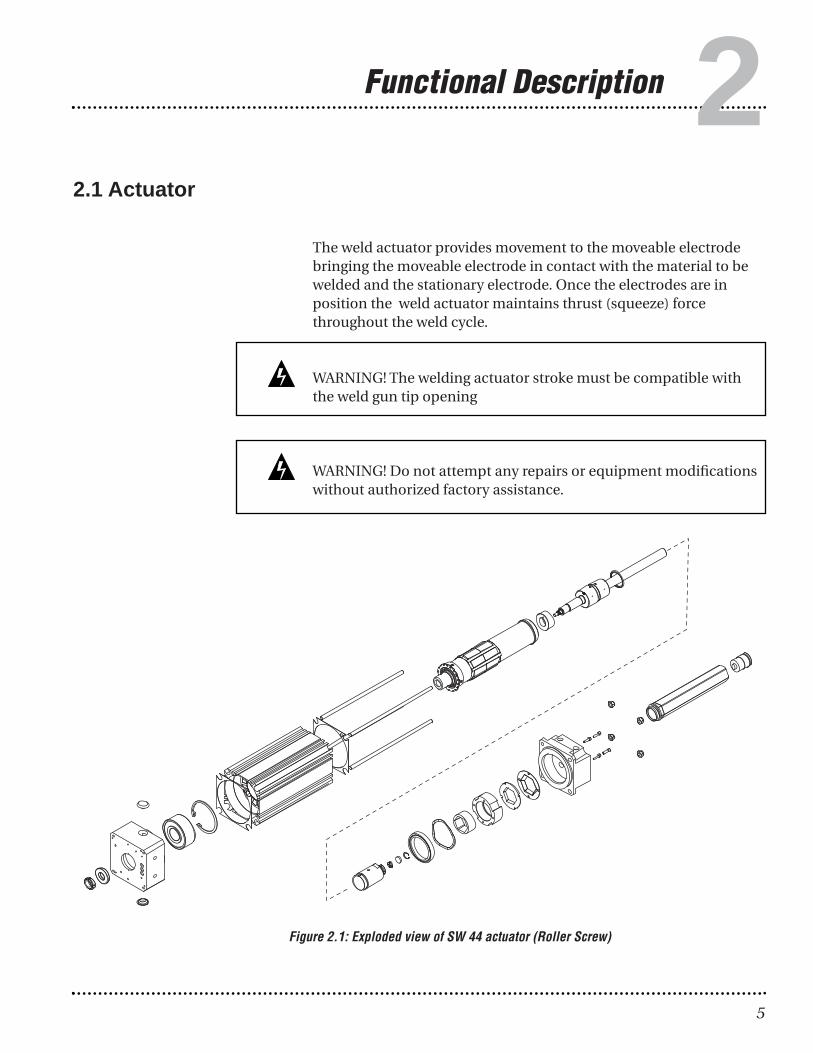
The weld actuator provides movement to the moveable electrodebringing the moveable electrode in contact with the material to bewelded and the stationary electrode. Once the electrodes are inposition the weld actuator maintains thrust (squeeze) forcethroughout the weld cycle.
WARNING! The welding actuator stroke must be compatible withthe weld gun tip opening
WARNING! Do not attempt any repairs or equipment modificationswithout authorized factory assistance.
5
Functional Description 2
Figure 2.1: Exploded view of SW 44 actuator (Roller Screw)

2.2 Fanuc Pulsecoder
The Fanuc Pulsecoder is mounted in a housing on the rear ofthe SW44. The pulsecoder provides position feedback to the7th axis controller/drive of the robot controller.
2 : F U N C T I O N A L D E S C R I P T I O N
6
OPTIONAL BATTERY BACKUP
Figure 2.2: Exploded view of Fanuc Pulsecoder for SW44
7
Basic Installation 33.1 Installing the W eld Actuator .
Please refer to the weld gun documentation supplied by the weldgun manufacturer for mechanical installation
3.2 Electrical W iringSee the electrical circuit diagram, supplied by the weld gunmanufacturer, that accompanied the weld gun at delivery.
CAUTION! Excessive side load on the output thrust rod of theactuator will dramatically reduce the life of the actuator and should beavoided. Side load can be caused from misalignment or loading that isnot inline with the actuator output thrust rod.
NOTE! The distance travelled under load dramatically affects life,when specified in cycle count. Tol-O-Matic recommends loadedstroke of less than 0.10" (2.5mm) when used at maximum actuatoroutput specifications.
3.3 Cable Routing
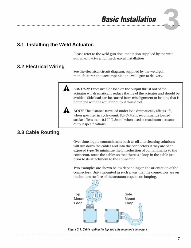
Over time, liquid contaminants such as oil and cleaning solutionswill run down the cables and into the connectors if they are of anexposed type. To minimize the introduction of contaminants to theconnector, route the cables so that there is a loop in the cable justprior to its attachment to the connector.
Two examples are shown below depending on the orientation of theconnectors. Units mounted in such a way that the connectors are onthe bottom surface of the actuator require no looping.
Figure 3.1: Cable routing for top and side mounted connectors
!
!
TopMountLoop
SideMountLoop

4.1 Inspection and Settings
Before commissioning the weld actuator, there are certaininspections and settings that must be completed. After allmaintenance activities, the gun must be inspected before it isreturned to service.
4.2 Inspection of Mechanical T ravel Limits.
The mechanical travel limits of the actuator must be verified toensure the actuator will not reach an internal hard limit duringnormal operation. The end of stroke bumpers should NOT beengaged during normal programmed servo actuator operation.
[Step 1] Turn the controller power off (see documentation forcontrols system for details). [Step 2] With the actuator installed on a weld gun, manually rotatethe servo gear extending the rod until the weld gun tips are closed.Record the distance the rod is extended as (d1).[Step 3] Remove one cap and manually rotate the servo gear,extending the rod, until the actuator reaches its end of travel. Record the distance the rod is extended as (d2).
The difference between the two measurements minus the gundeflection (d3) should be greater than end of stroke bumper (5 mm):
d2 - d1 - d3 ≥ 5mm
Figure 4.1: Manual operation of welding actuator
Inspection and Settings
8
4
ROTATE WHEEL = TUBE EXTENDS
ROTATE WHEEL = TUBE RETRACTS

4.3 Weld Motion Profi le
The rated force of 2500 lbs. (1.1 kN) is based on a duty cycle that willnot cause the maximum surface temperature of the actuator toexceed 155° F (68° C). The motion profile for the duty cycle used todetermine rated force is shown below. The motion profile is a 6 inch(152mm) move at max speed and acceleration. The weld move isrepeated with a one second dwell between welds and a 3 seconddwell every 10 welds.
Figure 4.2: Weld Motion Profile
Move # Initial Final Accel/ Move Move Velocity Velocity Decel Time Distance(in/sec) (in/sec) (in/sec2) (s) (in)
1 0 10 300 0.02 0.12 10 10 0 0.55 2.83 10 1 300 0.02 0.14 1 1 0 0.13 0.135 1 1 0 0.05 0.056 1 0 300 0.002 07 0 0 0 0.5 08 0 10 300 0.02 0.19 10 10 0 0.58 2.810 10 0 300 0.02 0.1
9
I N S P E C T I O N A N D S E T T I N G S : 4
Close Time Weld Time
Open Time
Time
Velocity
1
2
3
4 56 7
8
9
10
Weld Move

10
Repair and Maintenance5NOTE! Before starting any maintenance activities, make sure thatthe supply power is shut OFF.
- No lubrication is required during the service life of the servoweld actuator.
- The only user serviceable component in the servo weld actuator isthe Fanuc Pulsecoder. The pulsecoder is aligned to the servo weldactuator motor by an Oldham coupling. One segment of theOldham coupling is pressed onto the servo weld actuator shaftduring manufacturing of the actuator. Should this press fittingbecome altered, it is recommended that the actuator be returned toTol-O-Matic for realignment. The remaining Oldham componentsassure appropriate motor phasing alignment between thePulsecoder and motor windings through slotted connections. See figure 2.2 (page 4) for and exploded assembly view.
Disassembly of the weld actuator is not recommended. Servoweld actuators should be returned to Tol-O-Matic for evaluationand repair.
Contact the weldgun manufacturer for instructions on how to returnthe weld actuator for evaluation.
WARNING! Never rotate the actuator via the Pulsecoder connection.Doing so may result in the loss of phasing between the Pulsecoderand motor windings.

R E P A I R A N D M A I N T E N A N C E : 5
11
5.2 Pulsecoder Replacement
Figure 5.1: Exploded view of Fanuc Pulsecoder
DISASSEMBLY:1. Remove the 4 cover plate cap screws (8).
2. Remove cover (7).
3. Remove the gasket (2).
4. Disconnect the pulsecoder harness (18) from the pulsecoder (17).
5. Disconnect the motor temp sensor harness from motor leads (15, 13).
6. Remove the harness from the assembly.
7. Remove the 4 stainless steel socket head cap screws (6). Thepulsecoder is now free to come off the assembly. *Do not removethe black oxide fasteners, as they are holding the pulsecodertogether.
8
7
6
12
10
9
111
2
5
2
11
4
18
1413
15
16
17

ASSEMBLY:1. Orient the leadscrew shaft such that the pulsecoder coupler half is
oriented up/down with one starwheel port up and the other down.
2. Install the connecting portion of the pulsecoder coupler onto thecoupler half on the actuator.Orient the connector on the pulsecoder bottom left.
3. Position a connector gasket between the motor connector andencoder housing and with 4 socket head cap screws (10) and lockwashers attach the motor connector to the pulsecoder housing. –Use no Loctite on these fasteners.
4. Position the rubber boot over the pulsecoder harness and theinboard side of the connector.
5. Install the pulsecoder connector to the housing with 4 socket headcap screws, and lock washers (no Loctite). Be sure to locate therubber boot/gasket between the inboard side of connector and theoutside of the cap. Connect harness to the pulsecoder and connect2 pin motor temp leads to the harness connector.
6. Locate a gasket (2) between the pulsecoder housing (5) and thepulsecoder cover plate (7) and with the 4 cap screws (8), attach thepulsecoder housing and cover to the main bearing plate. Coil theharness so that it will not create any interference.
5 : R E P A I R A N D M A I N T E N A N C E
12

13
Appendix 6SW44 Motor Specifications LV3 (Low Voltage) HV3 (High Voltage)
Continuous Stall Torque 8.5 Nm (75.23 lb-in) 7.6 Nm (67.27 lb-in)
Peak Stall Torque 17.1 Nm (151.35 lb-in) 15.3 Nm (135.42 lb-in)
Continuous Stall Current 10.6 A RMS 5.9 A RMS
Peak Current 21.2 A RMS 11.9 A RMS
Number of Poles 8 8
Kt 0.80 Nm/A per phase RMS 1.29 Nm/A per phase RMS
Ke 0.46 V/rad/s L-L RMS 75.8 V/kRPM L-L RMS
Resistance @ 25C 0.74 ohms L-L 4.18 ohms L-L
Stator Inductance 3.65 mH L-L 15.7 mH L-L
Maximum Bus Voltage 325 Vdc 680 Vdc
Rated Speed @ Maximum Voltage 4,000 RPM 5000 RPM
Moment of Inertia 0.0013 Kg-m2 0.0013 kg-m2
Demagnetization Current 26 A RMS 26 A RMS
SW44 Actuator Specifications Ball Screw Roller Screw
Operating Force Up to 1,000 lbs. (4448 N) Less than 2,500 lbs. (11,120 N)
Peak Force 4400 lbf (19.6 kN) 4400 lbf (19.6 kN)
Continuous Force 1850 lbf (8.2 kN) 1850 lbf (8.2 kN)
Travel Under Force Up to 0.10" (2.5mm) travel Up to 0.10" (2.5mm) travelunder max load for 5M cycles under max load for 10M cycles
Side Load Unidirectional side load Unidirectional side load less than 1% axial load less than 3% axial load
Peak Speed 13 in/sec (330.2 mm/sec) 13 in/sec (330.2 mm/sec)
Max. Acceleration (no load) 350 in/sec2 350 in/sec2
SW44 Assembly Specifications Ball Screw Roller Screw
Frame Size 4.38 (111.3) x 4.38 (111.3) 4.38 (111.3) x 4.38 (111.3)
Length (with Fanuc Encoder) 15.53 (394.4) 15.53 (394.4)
Stroke 6.00 (152.4) 6.00 (152.4)
Screw Lead 5mm 5mm
Weight 30.9 lbs (14 kg) 30.9 lbs (14 kg)
6.1 Specifi cations

6.2 Thermal sensor specifi cations
The current thermal sensor will shut down the motor at 155° F(68°C). The motor should not perform a duty cycle that repeatedlygenerate motor temperatures above 155° F (68° C) or prematurebearing failure will result.
6.3 Connector pinout
Figure 6.1: Motor Power Connections
6 : A P P E N D I X
14
PULSECODERSIGNAL PIN NO.
SD ASD D
REQ FREQ G+5V J,K0V N,T
SEALED H+6VA R0VA S
A64 PULSECODER CONNECTIONSAS SUPPLIED BY FANUC
MS3102A-20-29PW
MOTOR SERVO AMP. MOTORCONNECTOR PHASE LEAD
A U REDB V BLKC W WHTD GND GRN/YEL
MOTOR POWER CONNECTIONS
MS3102A-18-10P
A
BC
D
A B
C
D
E
F
GH
J
K
L
MN
P
RS
T
Figure 6.2: Pulsecoder Connections

15
A P P E N D I X : 6
6.4 Troubleshooting Procedure
SYMPTOM CAUSE SOLUTION
No response from SW actuator Controller / Drive not enabled Enable Controller/Drive
Controller / Drive faulted Reset the Controller/Drive
Improper / Failed wiring Check the wiring
SW Actuator is enabled but is not Feedback cable may be damaged Test the feedback cable
operating or is operating erratically. Feedback wiring may be incorrect Verify feedback wiring
SW Actuator is operating but is Motor phases are wired incorrectly Verify correct wiring of not up to rated speeds/force or in incorrect order motor armature
Amplifier may be improperly tuned Check all gain settings
Amplifier may be set up improperly Check amplifier settings forfor SW actuator used number of poles, voltage,
current, resistance, inductance, inertia, etc.
Feedback is improperly aligned Contact Tol-O-Matic, Inc.
Actuator cannot move Force is too large for the capacity of Verify force requirementsthe weld gun. the actuator or too much friction is
present
Excessive side load Verify correct gun operation
Misalignment of output rod to Verify correct alignmentweld gun
Amplifier has too low current Verify correct amplifier andcapacity or is limited to too low settingsof current capacity
Actuator housing moves or Loose mounting Check actuator mounting
vibrates when shaft is in motion.
Amplifier is improperly tuned – Tune amplifierwrong gain settings
Actuator is overheating Duty cycle is higher than actuator Verify weld forces and rating actuator ratings
Actuator is being operated outside Reduce time that weld force of continuous ratings exceeds 1800 lbf (8007N)
Amplifier is poorly tuned, causing Check gain settingsexcessive unnecessary current to be applied to motor
6.5 Warranty
Tol-O-Matic, Inc., warrants product manufactured by it to be freefrom defects in material and workmanship for a period of one yearfrom date of shipment by Tol-O-Matic, Inc. If within such period anysuch product shall be proved to Tol-O-Matic, Inc.’s satisfaction to bedefective, such product shall either be repaired or replaced at Tol-O-Matic, Inc.’s option.
This warranty shall not apply:a. To product not manufactured by Tol-O-Matic, Inc. with respect to
product not manufactured by Tol-O-Matic, Inc. the warrantyobligations of Tol-O-Matic, Inc. shall in all respects conform and belimited to the warranty actually extended to Tol-O-Matic, Inc. by itssupplier.
b. To product which shall have been repaired or altered by partiesother than Tol-O-Matic, Inc., so as, in Tol-O-Matic, Inc.’s judgment,to affect the same adversely, or
c. To product which shall have been subject to negligence, accident, ordamage by circumstances beyond the control of Tol-O-Matic, Inc. orto improper operation maintenance or storage, or to other thannormal use and service.
The foregoing warranties are exclusive and in lieu of all otherexpressed and implied warranties whatsoever, including but notlimited to implied warranties of merchantability and fitness for aparticular purpose. Tol-O-Matic, Inc. shall not be subject to anyother obligations or liabilities whatsoever with respect to productmanufactured or supplied by Tol-O-Matic, Inc. or service renderedby it.
6 : A P P E N D I X
16

© Copyright 2005Tol-O-Matic, Incorporated. All rights reserved.Axidyne, Axiom, Tol-O-Matic and Excellence InMotion are registered trademarks of Tol-O-Matic Incorporated. All other products or brandnames are trademarks of their respectiveholders. www.tolomatic.com
11/05 Denison

TOL-O-MATIC, INC.3800 County Road 116Hamel, MN 55340763.478.8000 Telephone763.478.8080 Fax1.800.328.2174 Toll Freehttp://www.tolomatic.com