Embed Size (px)
Citation preview

04/06/2013 www.we-online.com/thermal_management
Webinar: Thermal Management 2013Würth Elektronik Circuit Board Technology
Page 1
Agenda
Basic Thermal Management
Possibilities of heat dissipation
Applications
www.we-online.com/thermal_management04/06/2013 Page 2
Basic Thermal Management
Possibilities for heat dissipation
Applications
www.we-online.com/thermal_management04/06/2013
Agenda
Page 3
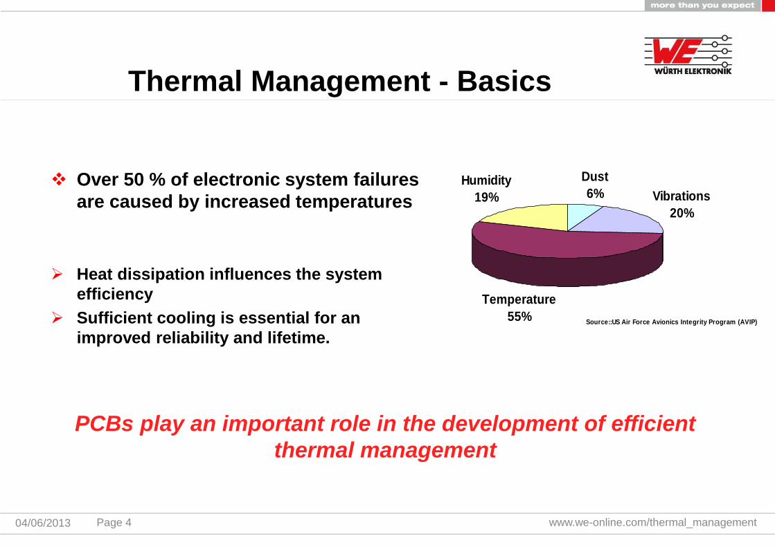
Over 50 % of electronic system failuresare caused by increased temperatures
Heat dissipation influences the systemefficiency
Sufficient cooling is essential for animproved reliability and lifetime.
www.we-online.com/thermal_management04/06/2013
Source::US Air Force Avionics Integrity Program (AVIP)
Dust
6% Vibrations
20%
Temperature
55%
Humidity
19%
Thermal Management - Basics
PCBs play an important role in the development of efficientthermal management
Page 4
Cooling strategies depend on different requirements of electronicsystems
Amount of thermal output
Available space / size of elements
Assembly technologies for components used
Complexity of circuit
Cooling concepts have to meet specific demands
Guarantee sufficient reliability
Provide for cost-benefit ratio
www.we-online.com/thermal_management04/06/2013
Thermal Management - Basics
Page 5
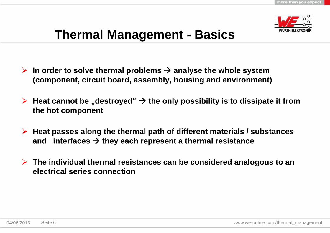
In order to solve thermal problems analyse the whole system(component, circuit board, assembly, housing and environment)
Heat cannot be „destroyed“ the only possibility is to dissipate it fromthe hot component
Heat passes along the thermal path of different materials / substancesand interfaces they each represent a thermal resistance
The individual thermal resistances can be considered analogous to anelectrical series connection
www.we-online.com/thermal_management04/06/2013
Thermal Management - Basics
Seite 6

System aspekts of thermal design
www.we-online.com/thermal_management04/06/2013
Rth (component)
Rth (com-pcb interconnection technology)
Rth (pcb)
Rth (contact area pcb-heatsink)
Rth (heatsink)
Rth (heat transfer to housing/environment)
warm
cold
Series connection of thermalresistances
Consideration of the entireheat path
Highest thermal resistance atinsulating layers, adhesivelayers, air inclusions, etc.
Maximise benefit by optimizingthe highest thermal resistor
Thermal Management - Basics
Seite 7
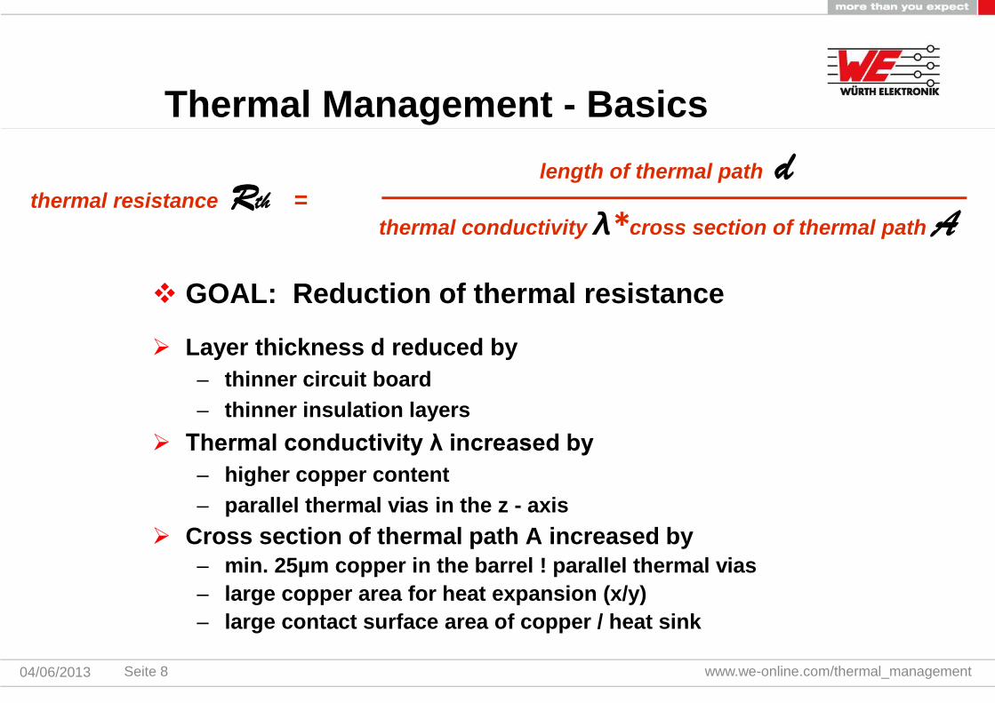
GOAL: Reduction of thermal resistance
Layer thickness d reduced by
– thinner circuit board
– thinner insulation layers
Thermal conductivity λ increased by
– higher copper content
– parallel thermal vias in the z - axis
Cross section of thermal path A increased by– min. 25µm copper in the barrel ! parallel thermal vias
– large copper area for heat expansion (x/y)
– large contact surface area of copper / heat sink
www.we-online.com/thermal_management04/06/2013
thermal resistance Rth =length of thermal path d
thermal conductivity λ*cross section of thermal path A
Thermal Management - Basics
Seite 8

www.we-online.com/thermal_management04/06/2013
Radiation: Emission of photons
Convection: Heat transfer through gases orfluids
Conduction: heat dissipation via solid objects
vertical: Thermal Via/Microvia/Buried Via
horizontal: copper foil heat spreading/heatsink
Types of heat dissipation
Thermal Management - Basics
Seite 9

Time for a poll
www.we-online.com/thermal_managementSeite 1004/06/2013
Through which measures can the thermalresistance be reduced?
Basics Thermal Management
Possibilities of heat dissipation
Applications
www.we-online.com/thermal_management04/06/2013
Agenda
Seite 11

Metal carrier with insulating layer and copper layer
Available as a complete base material
Simple circuits, usually only 1 35 microns copper layer in etching, solderresist
Disadvantage: - >1 copper layer is complex and expensive to produce quickly
- cut outs in aluminum or insulating layer are very expensive
Alternatives: thin DS board, Multilayer on aluminum
www.we-online.com/thermal_management04/06/2013
Possibilities of heat dissipation
IMS = Insulated Metal Substrate
Source: Bergquist
Aluminum or Copper
Seite 12

Plated through holes used as "ThermalVias“
Mechanically drilled vias
Good heat conduction in z-axis throughthe copper barrel (wall thickness min.25 microns)
If the printed circuit board thickness ismore than 0.7 mm, it is recommended tofill the vias and metallized over withcopper
www.we-online.com/thermal_management04/06/2013
Possibilities of heat dissipation
Thermal Vias
Seite 13
www.we-online.com/thermal_management04/06/2013
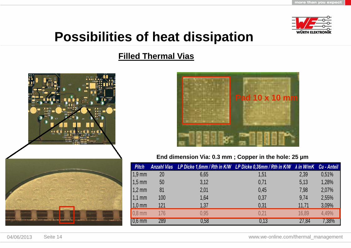
Filled Thermal Vias
End dimension Via: 0.3 mm ; Copper in the hole: 25 µm
Pitch Anzahl Vias LP Dicke 1,6mm / Rth in K/W LP Dicke 0,36mm / Rth in K/W λ in W/mK Cu - Anteil
1,9 mm 20 6,65 1,51 2,39 0,51%1,5 mm 50 3,12 0,71 5,13 1,28%1,2 mm 81 2,01 0,45 7,98 2,07%1,1 mm 100 1,64 0,37 9,74 2,55%1,0 mm 121 1,37 0,31 11,71 3,09%0,8 mm 176 0,95 0,21 16,89 4,49%0,6 mm 289 0,58 0,13 27,84 7,38%
Possibilities of heat dissipation
Pad 10 x 10 mm
Seite 14

www.we-online.com/thermal_management04/06/2013
Thermal Vias Filling Prozess
Copper
FR4
Copper
Drilling
Metallized hole
Vacuum fillingprocess
Curing
Brushing/Grinding
Metallized
Possibilities of heat dissipation
Seite 15

www.we-online.com/thermal_management04/06/2013
Ultra thin multilayer using blind Microviascombined with Buried Vias
Short heat path Microvias drilled directly intosolder pads no soldering problems
Complete decoupling of CTE mismatch
Combination Microvia/Buried Via
Possibilities of heat dissipation
Seite 16

www.we-online.com/thermal_management04/06/2013
Double sided PCB ormultilayer with individual baredie bonded and assembled
Individual heatsinks glued
Miniaturization throughreduction of the installationheight
Bare Die
Heatsink
Possibilities for heat dissipation
Seite 17
www.we-online.com/thermal_management04/06/2013
Heatsink
Bare Die
Possibilities for heat dissipation
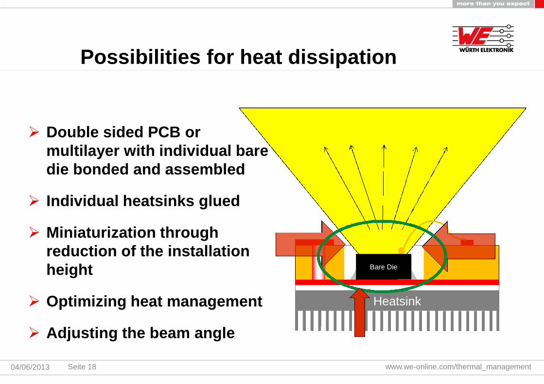
Double sided PCB ormultilayer with individual baredie bonded and assembled
Individual heatsinks glued
Miniaturization throughreduction of the installationheight
Optimizing heat management
Adjusting the beam angle
Seite 18
Time for a poll
www.we-online.com/thermal_managementSeite 1904/06/2013
Why is filling and covering of Thermal Viasrecommended?

Basics Thermal Management
Possibilities of heat dissipation
Applications
www.we-online.com/thermal_management04/06/2013
Agenda
Seite 20
www.we-online.com/thermal_management04/06/2013
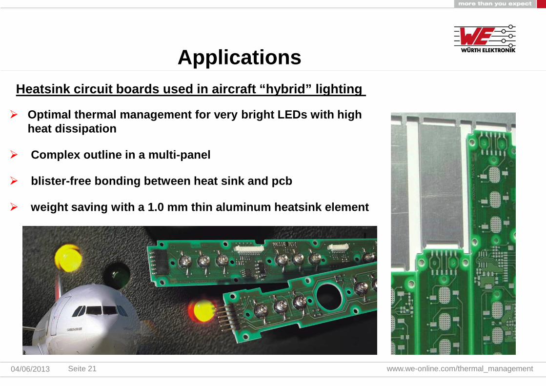
Heatsink circuit boards used in aircraft “hybrid” lighting
Applications
Optimal thermal management for very bright LEDs with highheat dissipation
Complex outline in a multi-panel
blister-free bonding between heat sink and pcb
weight saving with a 1.0 mm thin aluminum heatsink element
Seite 21
www.we-online.com/thermal_management04/06/2013
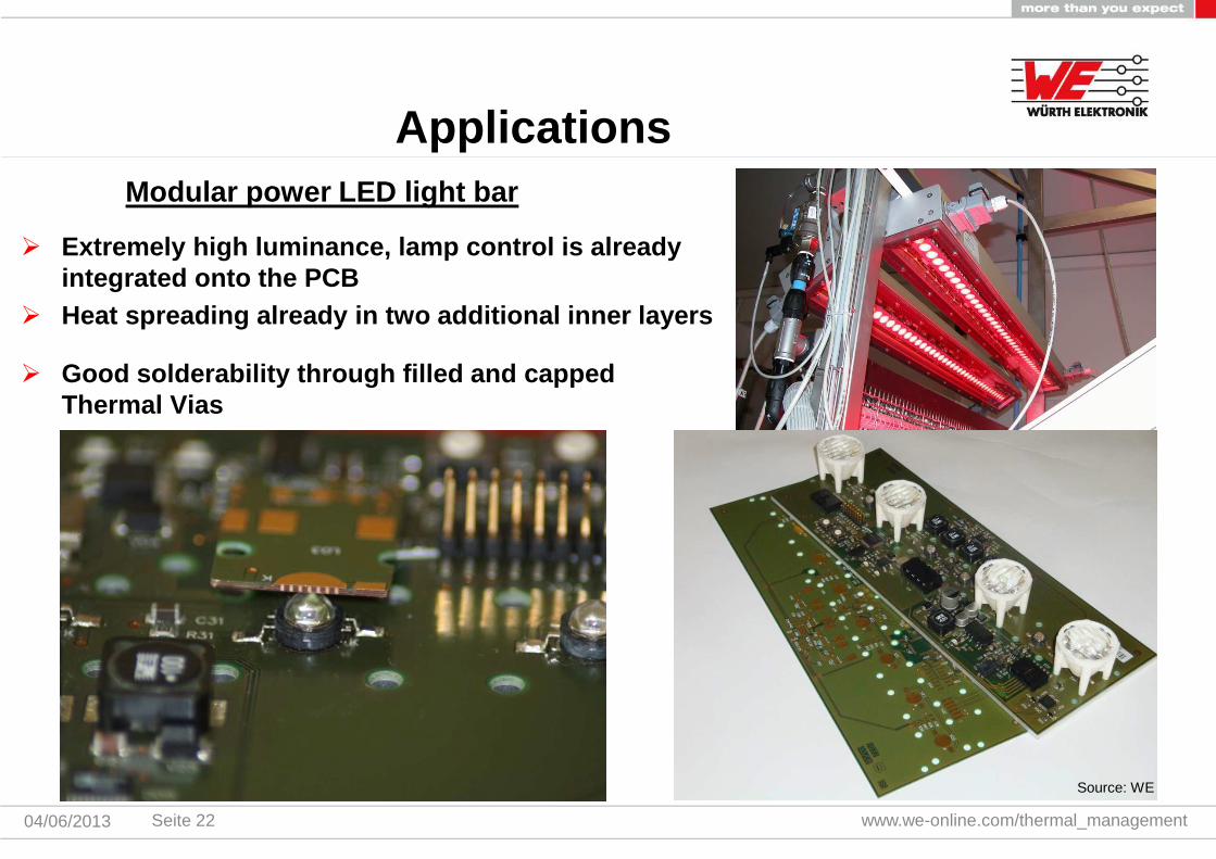
Modular power LED light bar
Applications
Extremely high luminance, lamp control is alreadyintegrated onto the PCB
Heat spreading already in two additional inner layers
Good solderability through filled and cappedThermal Vias
Source: WE
Seite 22

www.we-online.com/thermal_management04/06/2013
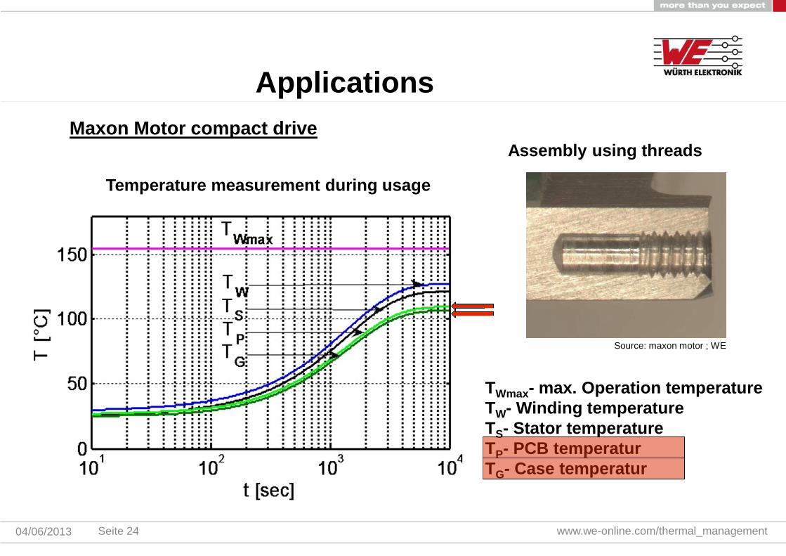
Maxon Motor compact drive
Thermal Vias
Threads onheatsink
Applications
Source: maxon motor ; WE
Compact drive with integrated controller, sensorand motor in an aluminum case
Robust, space-saving solution with high powerdensity (max. power 60W)
Highly dynamic, maintenance-free drive
Seite 23
www.we-online.com/thermal_management04/06/2013
Assembly using threads
Temperature measurement during usage
TWmax- max. Operation temperatureTW- Winding temperatureTS- Stator temperatureTP- PCB temperaturTG- Case temperatur
Maxon Motor compact drive
Source: maxon motor ; WE
Applications
Seite 24

www.we-online.com/thermal_management04/06/2013
Gearbox controller
Source: WE
Applications
4-layer Microvia - PCB with Aluminum Heatsinkelement
Optimized thermal management throughMicrovias in combination with Buried Vias
Ambient temperature –40°C to 125°C due topower dissipation
In series production for many years
Seite 25
www.we-online.com/thermal_management04/06/2013
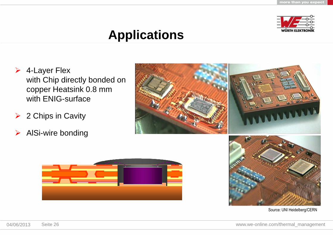
4-Layer Flexwith Chip directly bonded oncopper Heatsink 0.8 mmwith ENIG-surface
2 Chips in Cavity
AlSi-wire bonding
Source: UNI Heidelberg/CERN
Applications
Seite 26
www.we-online.com/thermal_management04/06/2013
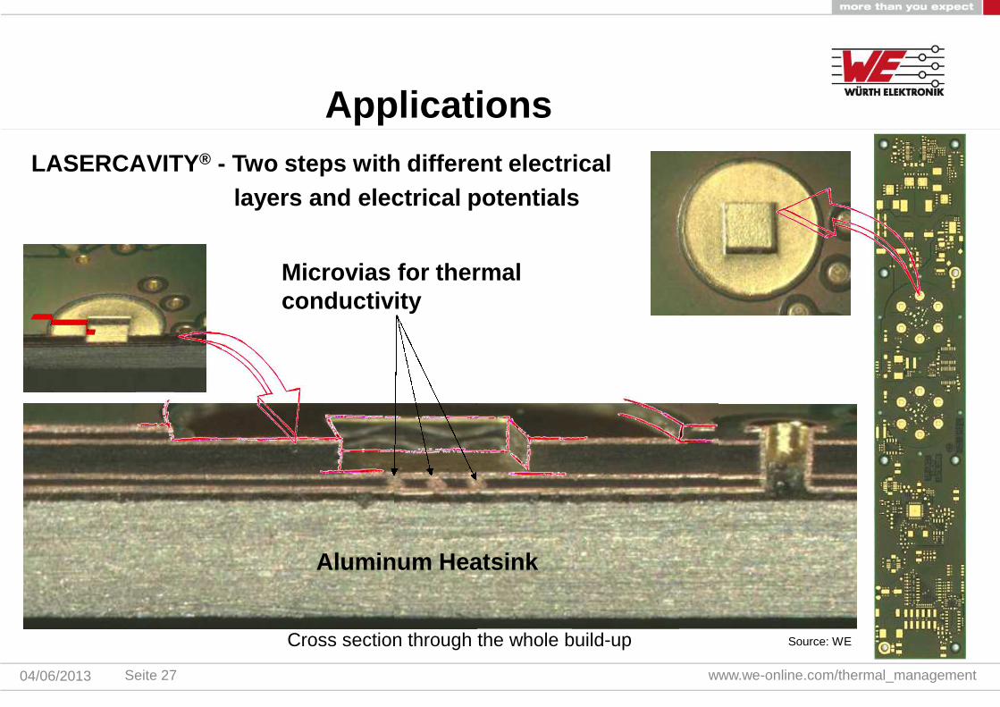
Cross section through the whole build-up
LASERCAVITY® - Two steps with different electrical
layers and electrical potentials
Aluminum Heatsink
Source: WE
Applications
Microvias for thermalconductivity
Seite 27

www.we-online.com/thermal_management04/06/2013
LASERCAVITY® LEDs + thermal management
400µm~ 12000 LEDs / 1dm²
Source: WE
Applications
Seite 28

04/06/2013 www.we-online.com/thermal_managementSeite 29
Thank you for your attention!
Bert HeinzWÜRTH ELEKTRONIK GmbH & Co. KGProdukt ManagementWärmemanagementCircuit Board TechnologyT.: +49 7622 397 477M.:+49 160 97211825E. [email protected]. www.we-online.com


![BA Tech to Market Roadmaps RFI webinar 040715.pptx [Read-Only] Werling_BA... · Building America Webinar: Tech ... Building America Technology Roadmap Thermal Load Thermal Load Thermal](https://img.dokumen.tips/doc/110x75/5f075a097e708231d41c8e37/ba-tech-to-market-roadmaps-rfi-webinar-read-only-werlingba-building-america.jpg)