Embed Size (px)
DESCRIPTION
Waves and Transmission Lines. Wang C. Ng. Traveling Waves. Envelop of a Standing Wave. Load. Waves in a transmission line. Electrical energy is transmitted as waves in a transmission line. Waves travel from the generator to the load (incident wave). - PowerPoint PPT Presentation
Citation preview
Wavesand
Transmission Lines
Wang C. Ng

Traveling Waves
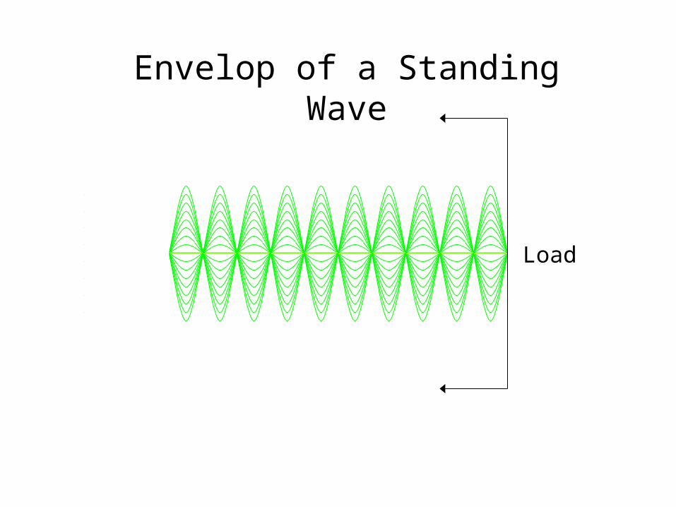
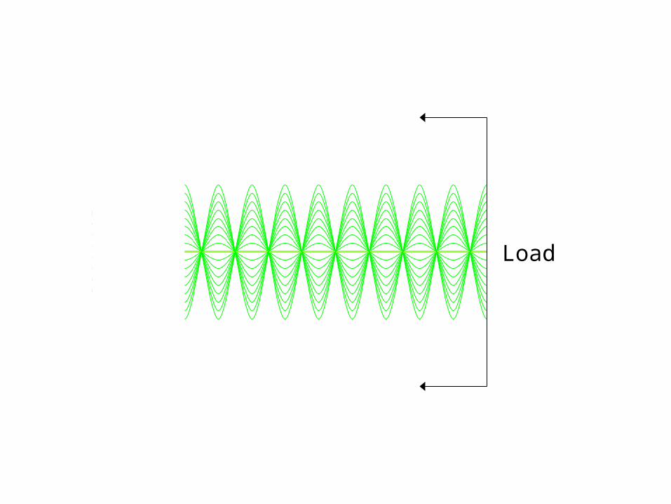
Load
Envelop of a Standing Wave
Waves in a transmission line
• Electrical energy is transmitted as waves in a transmission line.
• Waves travel from the generator to the load (incident wave).
• If the resistance of the load does not match the characteristic impedance of the transmission line, part of the energy will be reflected back toward the generator. This is called the reflected wave
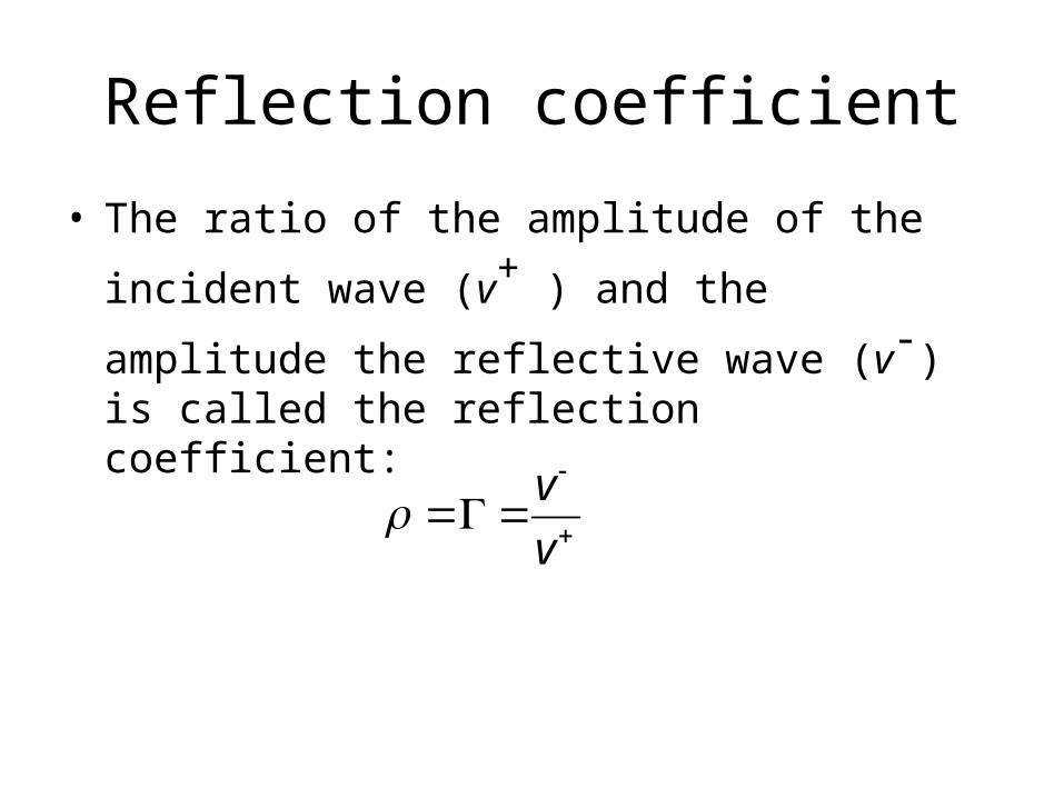
Reflection coefficient
• The ratio of the amplitude of the incident
wave (v+ ) and the amplitude the reflective
wave (v-) is called the reflection coefficient:
v
v
Reflection coefficient
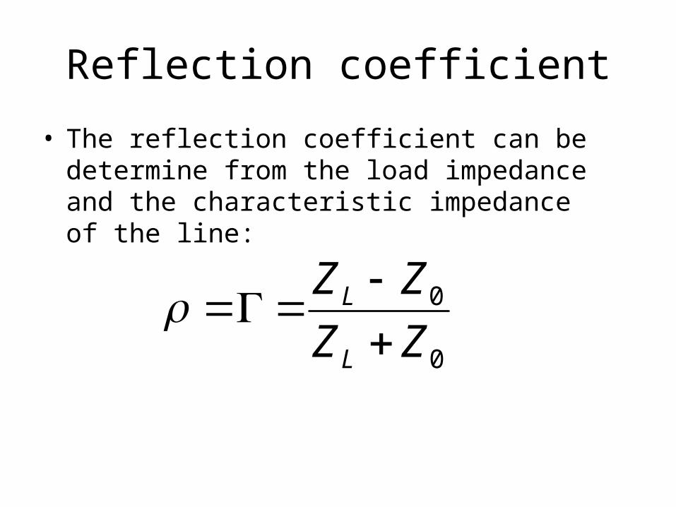
• The reflection coefficient can be determine from the load impedance and the characteristic impedance of the line:
0
0
ZZ
ZZ
L
L
Short-circuited Load
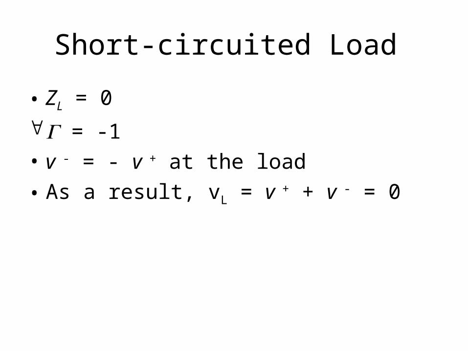
• ZL = 0
= -1
• v - = - v + at the load
• As a result, vL = v + + v - = 0

Load
Open-circuited Load
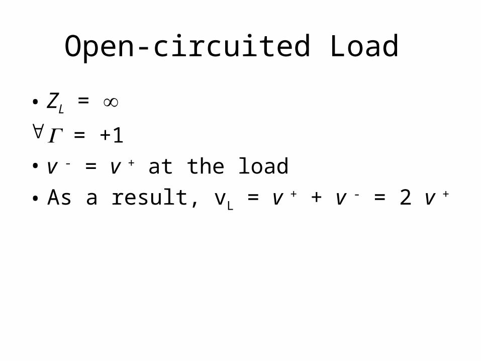
• ZL = = +1
• v - = v + at the load
• As a result, vL = v + + v - = 2 v +
Load
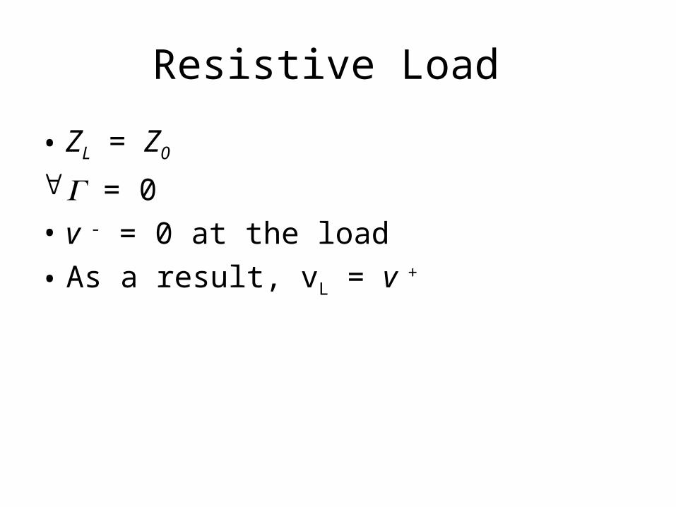
Resistive Load
• ZL = Z0
= 0
• v - = 0 at the load
• As a result, vL = v +
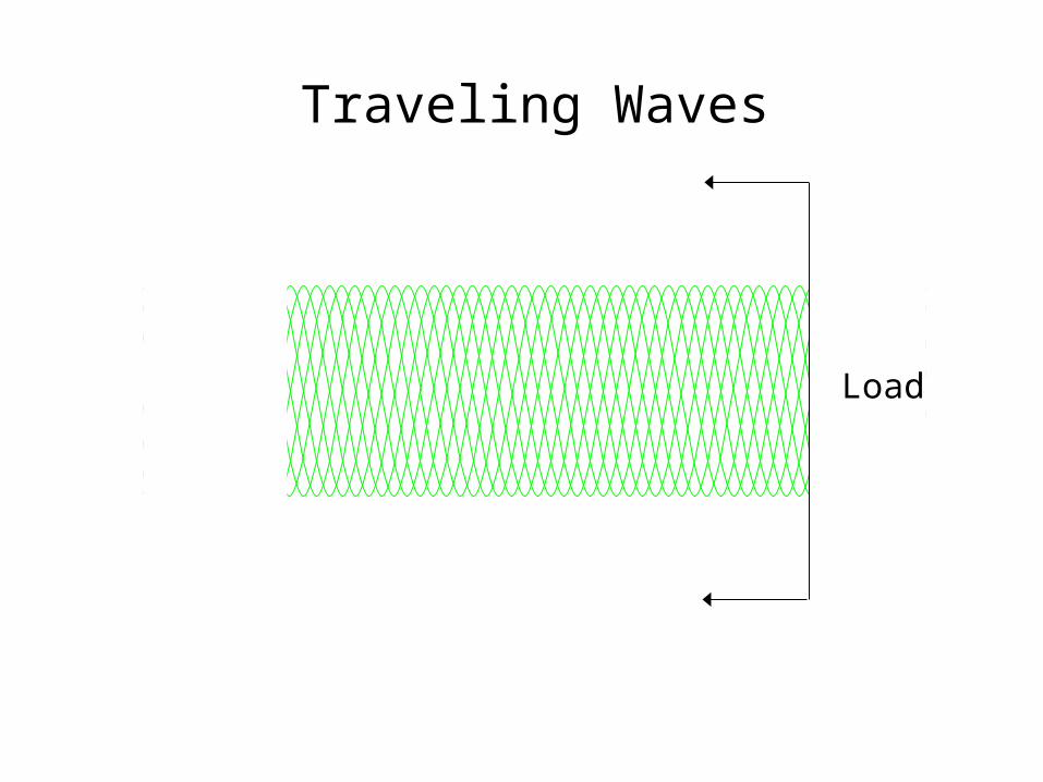
Traveling Waves
Load

Resistive Load
• ZL = 0.5 Z0
= - 1/3
• v - = -0.333 v + at the load
• As a result, vL = v + + v - = 0.667 v +

Composite Waves
Load

Resistive Load
• ZL = 2 Z0
= + 1/3
• v - = 0.333 v + at the load
• As a result, vL = v + + v - = 1.333 v +

Composite Waves
Load
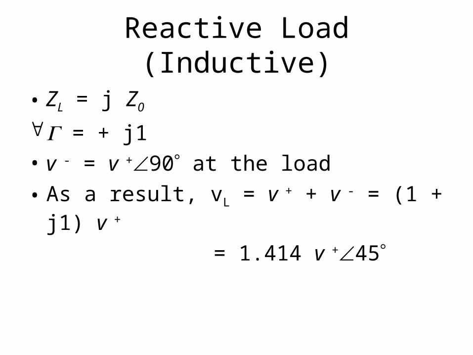
Reactive Load (Inductive)
• ZL = j Z0
= + j1
• v - = v +90 at the load
• As a result, vL = v + + v - = (1 + j1) v +
= 1.414 v +45
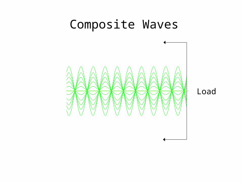
Composite Waves
Load
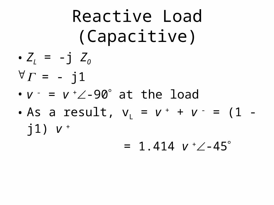
Reactive Load (Capacitive)
• ZL = -j Z0
= - j1
• v - = v +-90 at the load
• As a result, vL = v + + v - = (1 - j1) v +
= 1.414 v +-45
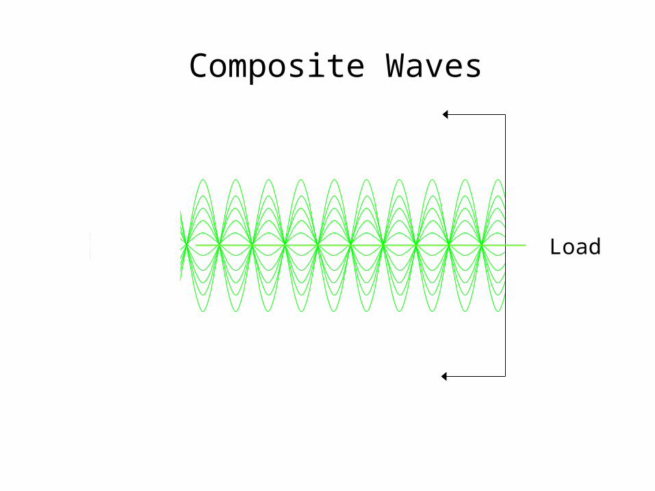
Composite Waves
Load

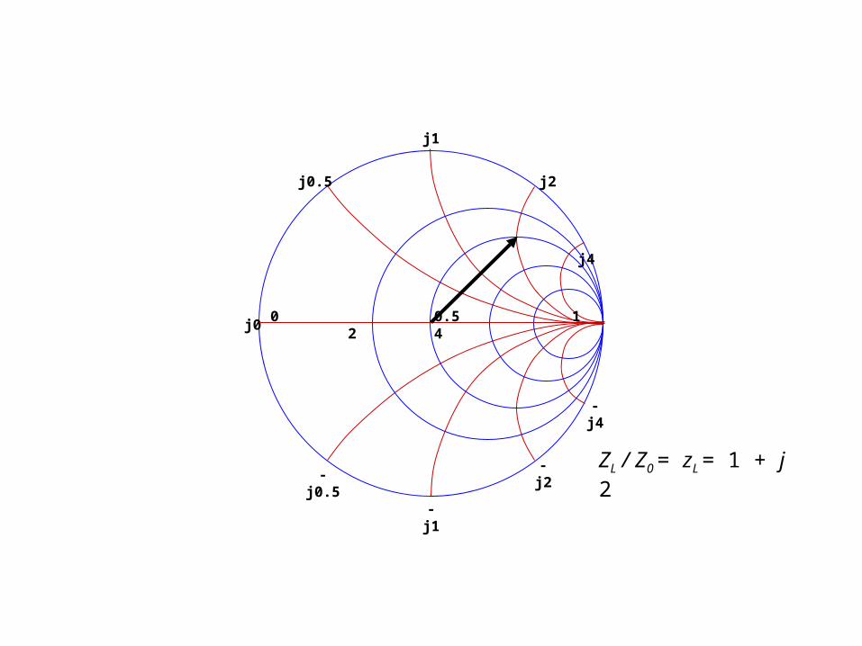
Smith Chart
Transmission Line
Calculator
-j2
-j4
-j1
-j0.5
j0.5
j1
j4
j2
j0 0 0.5 1 2 4
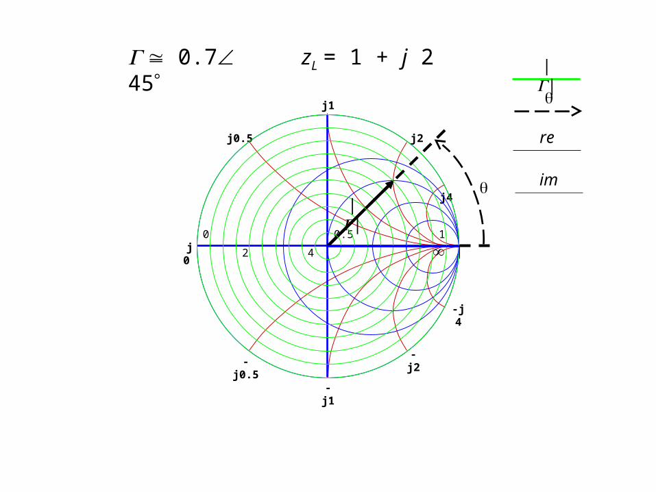
ZL / Z0 = zL = 1 + j 2
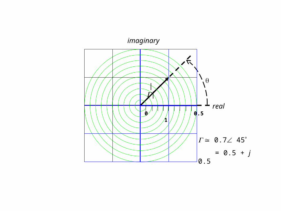
0 0.5 1
0.7 45
= 0.5 + j 0.5
real
imaginary
||
-j2
-j 4
-j1
-j0.5
j0.5
j1
j4
j2
j 0 0 0.5 1 2 4
zL = 1 + j 2 0.7 45
||
||
re
im

-j2
-j4
-j1
-j0.5
j0.5
j1
j4
j2
j0 0 0.5 1 2 4
zL = 1 + j 2
0.7 45
45
0
135
90
180
225
270
315
zL 1 j 2
zL 1
zL 1
0.5 0.5i
0.707
arg 45deg
-j2
-j4
-j1
-j0.5
j0.5
j1
j4
j2
j0 0 0.5 1 2 4
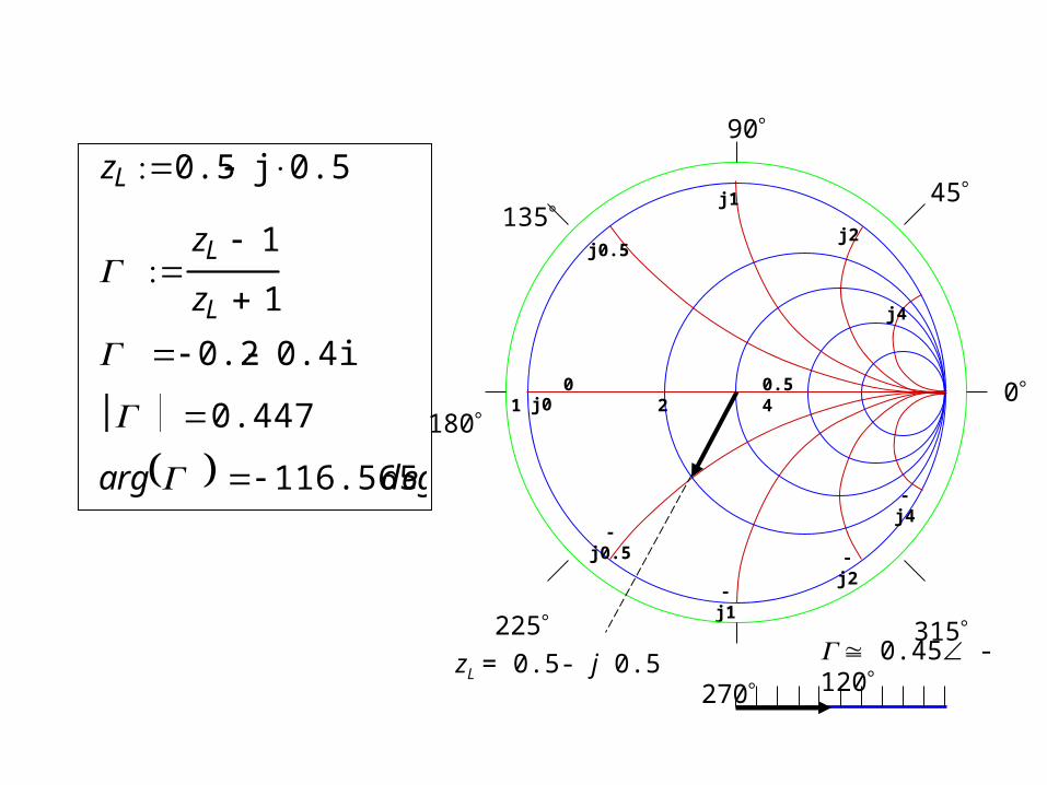
zL = 0.5- j 0.5 0.45 -120
45
0
135
90
180
225
270
315
zL 0.5 j 0.5
zL 1
zL 1
0.2 0.4i
0.447
arg 116.565 deg
| |
0 0.5 1
-j2
-j4
-j1
-j0.5
j0.5
j1
j4
j2
j0
0 0.5 1 2 4
45
0
135
90
180
225
270
315
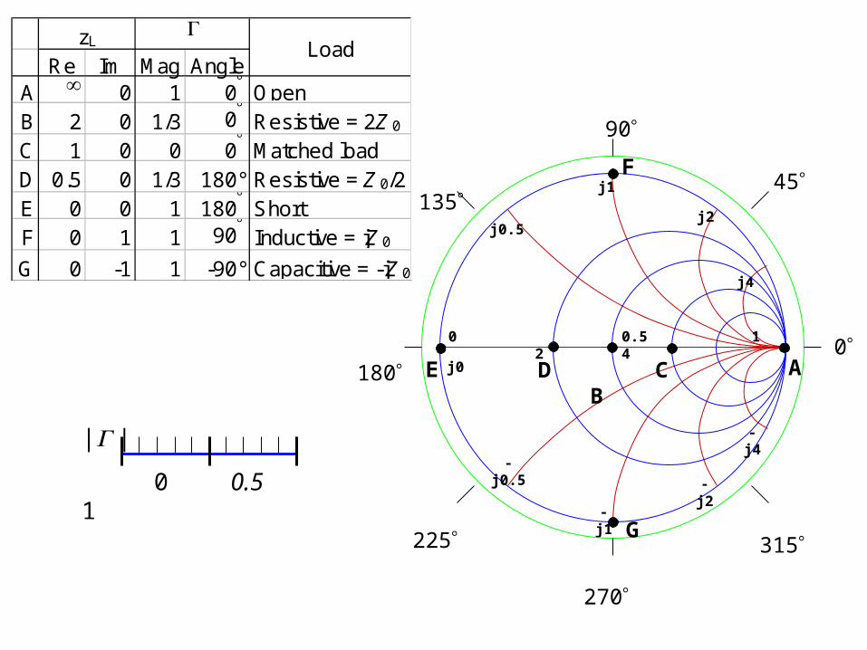
D C B E A
F
G
Re Im Mag AngleA 0 1 0 OpenB 2 0 1/3 0 Resistive = 2Z 0
C 1 0 0 0 Matched loadD 0.5 0 1/3 180° Resistive = Z 0/2E 0 0 1 180 Short F 0 1 1 90 Inductive = jZ 0
G 0 -1 1 -90° Capacitive = -jZ 0
zL Load