Embed Size (px)
Citation preview

Wavelet-based automatic identification method of axle distribution
information
Ningbo Wang1), Weixin Ren2) and Zhiwei Chen3)
1School of Civil Engineering, Central South University, Changsha 410075, China 2School of Civil and Hydraulic Engineering, Hefei University of Technology, Hefei
230009, China 3Department of Civil Engineering, Xiamen University, Xiamen 361005, China
ABSTRACT
Axle distribution information (e.g., axle distance, axle number, driving speed) identification is a key step in non-pavement bridge weigh-in-motion (BWIM) because it determines whether the bridge structure that is used for BWIM is suitable or not, thereby deciding the accuracy class of an as-built BWIM system. Extracting axle distribution information of a passing vehicle from bridge dynamic responses is a challenge to addressing the problem of BWIM. In this paper, wavelet transform analysis is proposed, and wavelet coefficient curve is used for axle identification as a substitute for dynamic response. The concept of driving frequency is proposed. The wavelet coefficient curve of the scale that corresponds to driving frequency is confirmed to have obvious axle information. A method for automatic axle distribution information identification is proposed. This method can obtain the specific wavelet scale through iterative computing and avoid subjective selection. To eliminate false peaks due to the interference caused by bridge vibration, the cross-correlation of the wavelet coefficients on two points is analyzed, and the integrand function that corresponds to the maximum value of the cross-correlation function is used to identify the peaks caused by axles. A numerical simulation of axle information identification of BWIM is performed. Results demonstrate that the proposed method acquires precise axle information from the responses of an axle-insensitive structure (e.g., girder) and decreases the requirement of sensitivity structure of BWIM. A full-scale simply supported bridge is used as study case to verify the feasibility of the proposed method for identifying the axle information from obscure dynamic response of beam structures caused by passing vehicles. Keywords: dynamic strain responses; axle distribution information; automatic identification; wavelet coefficient; driving frequency; specific scale
1)
Lecturer 2)
Professor 3)
Professor

1 INTRODUCTION
Axle information includes axle distance, number of axles, and vehicle speed, and it plays an important role in vehicle load identification, especially axle load identification. Bridge weigh-in-motion (BWIM) has been commonly used in bridge safety monitoring
because it is portable and inexpensive(O’Brien 2008, European Commission. 2001,
Lydon 2016). Axle detection directly affects the application scope and accuracy of the
B-WIM system and guides its development. When BWIM was first developed by Moses(Moses 1979), axle detection relied on connected facilities set on the road, such as reflective strips and third diagonal tube(Quilligan 2002). Auxiliary facilities have always had poor durability and are limited to provisional tests. Eventually, non-pavement axle detection was introduced(Mcnulty, 2003, Xiao 2006, Hitchcock 2011, Hitchcock 2012), which resulted in the nothing-on-road BWIM system. In this system, the transducer is not directly under vehicle load and has sufficient testing precision. The system was widely adopted for several decades. Recently, visual systems have been used for axle detection in the B-WIM system(Lydon 2016). This method can provide axle configurations without disrupting the flow of traffic by using a roadside camera system placed perpendicular to the traffic flow. According to the above analysis, the method of identifying axle information from bridge dynamic responses caused by a passing vehicle does not need additional devices and has an obvious advantage in economy and curability. This study extends the previous work to automatically identify axle information from bridge dynamic responses in combination with wavelet transform. In relation to the work developed in this paper, Kobayashi et al. (Kobayashi 2004) used the traditional local peak detection method for axle detection. Their method is suitable only for dynamic responses with a high signal-to-noise ratio and obvious peaks, such as responses of orthotropic steel deck bridge, which has a sensitive component to vehicle axles, such as the bending-plate WIM system. Navid et al. (Navid 2013) investigated the axle information identification of different vehicles that crossed a simply supported beam bridge with a 24.8 m span. The results of derivation and cross-correlation analysis differed widely, especially the results of wheelbase identification. In addition, when two peaks are close, denoising the early signal will cause the loss of peak information. Wavelet transform-based signal processing efficiently deals with the disadvantages of the traditional method. On the basis of the time-frequency localizing characteristic of wavelet transform, continuous wavelet transformation is applied to the dynamic response, and a wavelet coefficient curve is extracted to replace the original signal, which reduces the noise and makes the peak obvious. Chatterjee et al. (Chatterjee 2006) first applied wavelet transform to axle information identification. Chatterjee identified the axle information from the wavelet coefficient curve extracted from the dynamic response of a 6 m span frame bridge. In addition, influences of different wavelet basis functions and scaling coefficients were studied. rbio2.4 was determined as an ideal wavelet basis for axle information identification. Sakayanagi et al.(Sakayanagi 2008) used wavelet transform to increase the accuracy of axle weight and reduce the number of the

measurement points for orthotropic plate bridge. Lechner et al.(Lechner 2010) used a 7.5 m span simply supported plate bridge and a 12.6 m span plate bridge with elastomeric bearings as study cases to identify the axle information by extracting wavelet coefficient curve from the dynamic response of crack width. With the use of the wavelet coefficient as an alternative to dynamic response in these methods, the interference of testing noise is reduced and the application range is expanded somewhat. However, the subjectivity of wavelet coefficient selection is an ongoing problem; the wavelet coefficient under different scales always results in inconsistent peak value and axle information. In this study, a wavelet-based automatic identification method of axle distribution information is proposed. Together with the bridge response of different sections caused by passing traffic, a series discrete wavelet transform was introduced to obtain the wavelet coefficient curve of different wavelet scales. Then, the driving frequency caused by passing traffic and the corresponding specific scale are established through iterative computation, and the wavelet coefficient curves for different measurement points are chosen based on this specific scale. Through cross-correlation analysis between the positive part of the above wavelet coefficient curves, the integrand curve is extracted by using a maximum interrelation algorithm, which could eliminate the false peaks due to bridge vibration and obtain exactly identical results. This paper is organized as follows: Section 2 introduces the concept of driving frequency by passing vehicles. Section 3 presents the theoretical approaches and processes of automatic identification of axle information from bridge dynamic responses. Section 4 shows a numerical example of vehicle-bridge coupling vibration to verify the method of this article. Section 5 describes an experimental test used to illustrate the feasibility of the proposed method. Finally, some conclusions are presented in Section 6.
2 PRELIMINARY REMARKS
Preliminary insights into the driving frequency and wavelet scale provide hints for the automatic identification technique described in Section 3. When the wavelet transform is performed on bridge dynamic responses, only the wavelet coefficient of a specific scale can represent the vehicle axle information well, and this specific scale is always decided by the driving frequency of passing traffic. The frequency components of bridge vibration response induced by passing vehicles mainly include two types: (1) free vibration frequency related to bridge vibration and (2) driving frequency related to vehicle loading, which is determined by the speed and wheelbase, among others. When identifying axle information, driving frequency is the effective component, and bridge vibration is seen as interference. 2.1 Driving frequency of passing traffic Yang et al.(Yang 2004, Yang 2005) defines driving frequency of a single-axle vehicle or an equivalent single-axle vehicle (when the ratio of the wheelbase to the length of the span is small) that uniformly crosses the bridge as nπv/L, where v and L are the speed and the length of the span, respectively. For small-span and medium-span bridges, as well as the secondary system of large-span bridges (Fig. 1), the vehicle cannot be
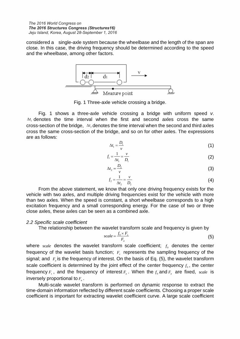
considered a single-axle system because the wheelbase and the length of the span are close. In this case, the driving frequency should be determined according to the speed and the wheelbase, among other factors.
Fig. 1 Three-axle vehicle crossing a bridge.
Fig. 1 shows a three-axle vehicle crossing a bridge with uniform speed v.
1t denotes the time interval when the first and second axles cross the same
cross-section of the bridge, 2t denotes the time interval when the second and third axles
cross the same cross-section of the bridge, and so on for other axles. The expressions are as follows:
11
Dt
v (1)
1
1 1
1 vf
t D
(2)
22
Dt
v (3)
2
2 2
1 vf
t D
(4)
From the above statement, we know that only one driving frequency exists for the vehicle with two axles, and multiple driving frequencies exist for the vehicle with more than two axles. When the speed is constant, a short wheelbase corresponds to a high excitation frequency and a small corresponding energy. For the case of two or three close axles, these axles can be seen as a combined axle.
2.2 Specific scale coefficient The relationship between the wavelet transform scale and frequency is given by
0sc s
a
f Fale
F
(5)
where scale denotes the wavelet transform scale coefficient; 0f denotes the center
frequency of the wavelet basis function; sF represents the sampling frequency of the
signal; and aF is the frequency of interest. On the basis of Eq. (5), the wavelet transform
scale coefficient is determined by the joint effect of the center frequency0f , the center
frequencysF , and the frequency of interest
aF . When the0f and
aF are fixed, scale is
inversely proportional toaF .
Multi-scale wavelet transform is performed on dynamic response to extract the time-domain information reflected by different scale coefficients. Choosing a proper scale coefficient is important for extracting wavelet coefficient curve. A large scale coefficient
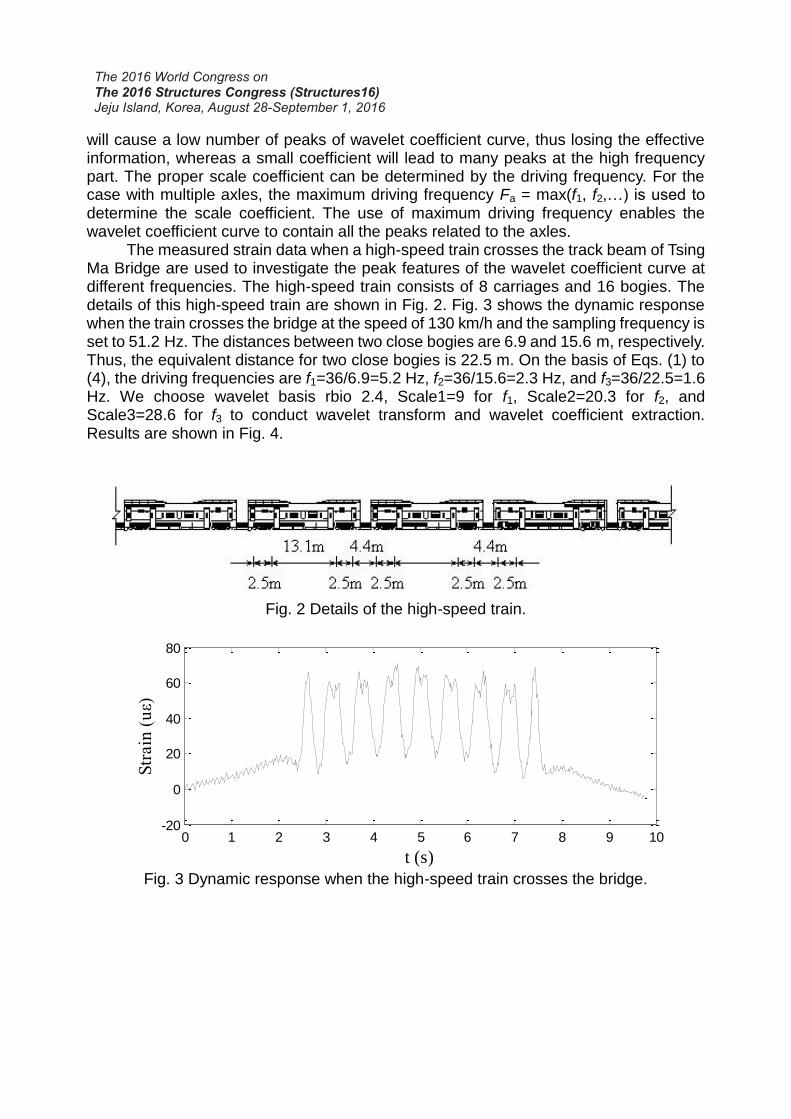
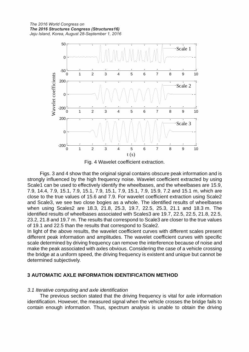
will cause a low number of peaks of wavelet coefficient curve, thus losing the effective information, whereas a small coefficient will lead to many peaks at the high frequency part. The proper scale coefficient can be determined by the driving frequency. For the case with multiple axles, the maximum driving frequency Fa = max(f1, f2,…) is used to determine the scale coefficient. The use of maximum driving frequency enables the wavelet coefficient curve to contain all the peaks related to the axles. The measured strain data when a high-speed train crosses the track beam of Tsing Ma Bridge are used to investigate the peak features of the wavelet coefficient curve at different frequencies. The high-speed train consists of 8 carriages and 16 bogies. The details of this high-speed train are shown in Fig. 2. Fig. 3 shows the dynamic response when the train crosses the bridge at the speed of 130 km/h and the sampling frequency is set to 51.2 Hz. The distances between two close bogies are 6.9 and 15.6 m, respectively. Thus, the equivalent distance for two close bogies is 22.5 m. On the basis of Eqs. (1) to (4), the driving frequencies are f1=36/6.9=5.2 Hz, f2=36/15.6=2.3 Hz, and f3=36/22.5=1.6 Hz. We choose wavelet basis rbio 2.4, Scale1=9 for f1, Scale2=20.3 for f2, and Scale3=28.6 for f3 to conduct wavelet transform and wavelet coefficient extraction. Results are shown in Fig. 4.
Fig. 2 Details of the high-speed train.
0 1 2 3 4 5 6 7 8 9 10-20
0
20
40
60
80
t (s)
Str
ain
(u
ε)
Fig. 3 Dynamic response when the high-speed train crosses the bridge.
0 1 2 3 4 5 6 7 8 9 10-50
0
50
Scale 1
0 1 2 3 4 5 6 7 8 9 10-200
0
200
Wav
ele
t co
eff
icie
nts
Scale 2
0 1 2 3 4 5 6 7 8 9 10-200
0
200
t (s)
Scale 3
Fig. 4 Wavelet coefficient extraction.
Figs. 3 and 4 show that the original signal contains obscure peak information and is strongly influenced by the high frequency noise. Wavelet coefficient extracted by using Scale1 can be used to effectively identify the wheelbases, and the wheelbases are 15.9, 7.9, 14.4, 7.9, 15.1, 7.9, 15.1, 7.9, 15.1, 7.9, 15.1, 7.9, 15.9, 7.2 and 15.1 m, which are close to the true values of 15.6 and 7.9. For wavelet coefficient extraction using Scale2 and Scale3, we see two close bogies as a whole. The identified results of wheelbases when using Scales2 are 18.3, 21.8, 25.3, 19.7, 22.5, 25.3, 21.1 and 18.3 m. The identified results of wheelbases associated with Scales3 are 19.7, 22.5, 22.5, 21.8, 22.5, 23.2, 21.8 and 19.7 m. The results that correspond to Scale3 are closer to the true values of 19.1 and 22.5 than the results that correspond to Scale2. In light of the above results, the wavelet coefficient curves with different scales present different peak information and amplitudes. The wavelet coefficient curves with specific scale determined by driving frequency can remove the interference because of noise and make the peak associated with axles obvious. Considering the case of a vehicle crossing the bridge at a uniform speed, the driving frequency is existent and unique but cannot be determined subjectively.
3 AUTOMATIC AXLE INFORMATION IDENTIFICATION METHOD
3.1 Iterative computing and axle identification
The previous section stated that the driving frequency is vital for axle information identification. However, the measured signal when the vehicle crosses the bridge fails to contain enough information. Thus, spectrum analysis is unable to obtain the driving

frequency. On the basis of the idea that axle information determines the driving frequency and that the driving frequency can be used to extract the proper wavelet coefficient curve for axle information identification, we propose an iterative computing method for axle information identification. The related steps are as follows: (1) The range of the driving frequency is determined. The range of driving frequency depends on the speed and wheelbase, and is expressed by
fmax = vmax/Dmin (6) fmin = vmin/Dmax (7)
where vmax and vmin denote the maximum and minimum speed limits, respectively; and Dmax and Dmin denote the maximum and minimum wheelbases, respectively. For the BWIM on the railway bridge, these parameters can be determined according to the relevant design code. (2) The initial driving frequency is computed. We uniformly divide the range of the driving frequency as follows:
max max max min2f f f f f f f (8)
max minf ff
n
(9)
where n is an integer that should be as big as possible. In practical application, we choose the driving frequencies in Eq. (8) to extract the wavelet coefficient curve. When the driving frequency is high, the wavelet coefficient curve presents burr. When the driving frequency is low, the wavelet coefficient curve is too smooth, which is unable to reflect the axle information. Therefore, selecting a proper driving frequency is important. The number of peaks of the wavelet coefficient curve extracted by using the proper driving frequency is the number of axles. A vehicle usually has fewer than seven axles. Thus, the maximum number limit of peaks (denoted by Nmax) should be set. When the driving frequency is used to extract the wavelet coefficient curve, its peaks are more than Nmax, and this driving frequency is regarded as improper. We then use the next driving frequency until we find the proper driving frequency f0. The proper threshold value equal to 20% of the max amplitude is set, and the number of peaks is established by comparing the peak value and the threshold value, as shown in Fig. 5.
0 5 10 15 20 25 30 35 40-20
0
20
40
60
Str
ain
(με)
t(s)
0 5 10 15 20 25 30 35 40-60
-20
20
60
100
Wa
ve
let co
effic
ien
ts
Fig. 5 Calculation of the number of peaks and the threshold.
threshold

After the initial driving frequency is determined as f0, we compute the accurate driving frequency iteratively and identify the axle information based on the measured dynamic responses of two points. The entire task is performed on MATLAB platform. The corresponding calculation flowchart is shown in Fig. 6.
Initial vibration frequency and wavelet scale
Extract the wavelet coefficient
curve from the original signal and
identify the axle information
0
f 0
a 1j
j
a j
f
1j j
v
j
a aTol
a
1j j
N j
a a
i jd
jv
N j
v v
i iN jd d
Extract the wavelet
coefficient curve
from the original
signal and identify
the axle information
Compute driving frequency and scale
No
Yes
Input: Dynamic strain responses of two points
Fig. 6 Flowchart of the axle information identification.
3.2 Eliminating interference peaks Bridge vibration response induced by vehicles crossing the bridge contains bridge natural frequency and driving frequency. For the bridge with structural components that are sensitive to the axle, driving frequency is dominant, and the peaks related to the axle are clear and can be extracted easily. The bridge vibration response is contaminated by noise, which causes excess peaks. In this case, wavelet transform technique can clarify

the peaks of the wavelet scale coefficient curve, but it fails to remove the interference due to bridge vibration when driving frequency and bridge free vibration frequency are close. Removing the induced interference is important because doing ensures that axle information can be extracted easily from the obscure original signal. Assume a wavelet scale coefficient curve that corresponds to the points at two different cross sections, f(t) and g(t), t1<t<t2,t1, t2 denote the beginning time and ending time of the signal, respectively. We consider only the peaks whose values are positive. Thus, we take f +(t)、g+(t) as the study target. The expressions are given by
1 21
0 else
t t tt
,
, (10)
F t f t t (11)
G t g t t (12)
C F t G t dt (13)
Even though the interference due to bridge vibration exists, the peak information induced by vehicle loading is dominant. Thus, 0t F t G t when C is
maximum can be used for axle information identification. t uses the great correlation
between the effective peaks of F(t) and G(t) (0= ), while the correlation between false
peaks is weak. Multiplication is used to retain and enlarge useful peaks and reduce false peaks, thereby eliminating the interference due to the bridge vibration and extracting axle information from obscure dynamic response. This idea of removing false peaks will be verified by numerical example and experimental studies in Sections 3 and 4.
4 NUMERICAL CASE STUDY
A simply supported beam bridge on which a three-axle vehicle crosses is used as a case study. The parameters of the bridge are as follows: span L=16 m, distance between neutral axis and the bottom of beam La=0.8 m, bending rigidity EI=4.36x10⁹ Nm2, linear density Ρa=1.07e4kg/m, damping coefficient ξ=0.02, and first bending frequency f1=3.91 Hz. Bakht (Bakht 2009) maintains that the dynamic response at the points close to the support is more sensitive for the beam bridge. Accordingly, we use the dynamic responses of points at 1/8 and 7/8 L to extract axle information, and the measured points are installed at the bottom of the main girder. The details of the vehicle can be found in Ref. (Zhu 2005). The wheelbase between the first and second axles is 3.66 m, and the wheelbase between the second and third axles is 6.20 m. A total of 10 degrees of freedom, including vehicle body vertical vibration, rotation, and wheel vertical vibration, is considered. For this vehicle and the bridge model, the patch contact of the tire and the road surface is simplified as a point contact. If the surface classification is poor, then this contact condition will overestimate the dynamic deflection of the bridge and magnify the effect of road surface roughness (Yin 2011). Thus, a good road roughness grade such as ISO (1995) A index is assumed in this numerical study. Within the MATLAB framework, Newmark-β method is utilized to compute the dynamic strain signal, and the computing frequency is 500 Hz. The

simulated dynamic strains are used to detail the procedure for employing the proposed method to identify axle information. The identified results of velocity and wheelbases at different speeds are listed in Table 1. The results verify that our method is feasible for the extraction of axle information from the obscure original signal even when the driving frequency is close to the bridge natural frequency and in cases with a high driving speed. The identified velocities that correspond to the speeds of 2 m/s, 4 m/s,…, 36 m/s are shown in Fig. 7, which shows that the identified velocities agree fairly well with the real value. Fig. 8 shows the identified wheelbase results of different scenarios related to different speeds. From Fig. 8, we know that the result for the wheelbase (3.66m) between the first and the second axles is not as accurate as that for the wheelbase (6.20m) between the second and the third axles. A relatively large error exists when the speed is 14m/s–24m/s because the driving frequency is close to the bridge natural frequency, which causes a larger bridge vibration interference and influences the identified results.
Table 1 Identified results of the numerical case
No. Speed (m/s) Wheelbase D12(m) Wheelbase D23(m)
True value
Identified value
True value
Identified value
True value
Identified value
1 2 2.03
3.66
3.86
6.20
6.25 2 4 4.05 3.87 6.22 3 6 6.01 3.84 6.17 4 8 8.02 3.83 6.19 5 10 10.06 3.75 6.24 6 12 11.90 3.50 6.12 7 14 14.85 4.36 6.62 8 16 16.17 4.08 5.73 9 18 18.92 4.43 6.39 10 20 21.2 4.45 6.40 11 22 22.22 4.64 5.71 12 24 23.72 3.75 6.25 13 26 24.90 3.34 5.63 14 28 28.17 3.66 6.25 15 30 29.85 3.64 6.15 16 32 31.41 3.58 6.09 17 34 33.33 3.53 6.07 18 36 35.50 3.62 6.18

0 5 10 15 20 25 30 35 400
5
10
15
20
25
30
35
40
Driving speeds (m/s)
Iden
tifi
ed
sp
eed
s (m
/s)
Fig. 7 Speed identification of the different scenarios.
Fig. 8 Wheelbase identification of the different scenarios.
We then studied the scenario that corresponds to the speed of 15 m/s. The resulting driving frequencies are 4.09 and 2.42 Hz by the two groups of adjacent axles, respectively, and the former is quite close to the bridge natural frequency of 3.91 Hz. The proposed method is used to extract the wavelet coefficient curves of a specific scale from the dynamic strain response of points at 1/8 L and 7/8 L. The wavelet coefficient and its corresponding initial signal of two points are shown in Fig. 9, which shows that the wavelet coefficient of a specific scale can be effective for denoising and making peaks obvious. For the driving frequency that is close to the bridge natural frequency, from Fig. 9,

we can also determine that the extracted wavelet coefficient contains the effective peaks that correspond to the axle and the false peaks due to bridge vibration as well. In this situation, cross-correlation analysis on the positive part of wavelet coefficient curve can be used. The state of two coefficient curves when the cross-correlation function is maximum is shown in Fig. 10(a), and the convolution operation result on integrand function is shown in Fig. 10(b). Fig. 10(b) shows that the interference of false peaks due to bridge vibration is removed.
0 0.5 1 1.5 2 2.5 3 3.5-20
0
20
40
60
Str
ain
(με)
t(s)
0 0.5 1 1.5 2 2.5 3 3.5-20
0
20
40
60
Wa
ve
let co
effic
ien
ts
0 0.5 1 1.5 2 2.5 3 3.5-20
0
20
40
60
Wa
ve
let co
effic
ien
ts
1/8L:Dynamic response
7/8L:Dynamic response
1/8L:Wavelet coefficient
7/8L:Wavelet coefficient
Fig. 9 Dynamic strain response and wavelet coefficient with the specific scale.
0 0.5 1 1.5 2 2.5 3 3.5 4 4.5-20
0
20
40
60
Wav
ele
t co
eff
icie
nts
1/8L:F(t-τ0)
7/8L:G(t)
0 0.5 1 1.5 2 2.5 3 3.5 4 4.5-1000
0
1000
2000
3000
t (s)
F(t
-τ0).
*G
(t)
Fig. 10 Integrand function when the cross-correlation function is maximum and two
coefficient curves.

5 EXPERIMENTAL VERIFICATION
The Huangkou Bridge, which is located in Huangshan city, Anhui Province, is a multi-span simply supported beam bridge (Fig. 11). The bridge is 20 m long and 18.5 m wide. The driving way is 14 m wide, and the sideway is 2.25 m wide. The bridge consists of eight T-shaped girders. The measured first bending frequency is 3.06 Hz. This real bridge is used to verify the feasibility of the proposed method. The measured cross-sections and arrangement of measuring points are shown in Fig. 12.
Fig. 11 Huangkou Bridge.
Fig.12 Arrangement of measuring points.

The vehicle drives through the bridge using the second lane. The tested vehicle is three-axled, the wheelbase between the first and second axles is 4.0m, and the wheelbase between the second and third axles is 1.4 m. The axle weights are 89.4, 179.2, and 178.2 kN. The speeds are controlled at 5, 10, 20, and 40 km/h. The measured dynamic responses are shown in Fig. 13, from which we know that a high speed corresponds to a strong interference because the driving frequency becomes closer to the natural frequency of the bridge.
0 5 10 15 20 25-50
0
50
100
150
Str
ain
/με
(a)
Sensor 1 Sensor 2 Sensor 3 Sensor 4
0 5 10 15 20 25-50
0
50
100
150
(b)
0 5 10 15 20 25-50
0
50
100
150
200
Distance/m
Str
ain
/με
(c)
0 5 10 15 20 25-50
0
50
100
150
200
Distance/m
(d)
(a) v=5 km/h, (b) v=10 km/h, (c) v=20 km/h, and (d) v=40 km/h
Fig. 13 Dynamic strain response of the measurement points.
Our proposed method automatically determines the specific scale and identifies the axle information. The identified results of four scenarios that correspond to four different speeds are shown in Fig. 14, which shows that the peaks related to axles are obvious. For the scenarios that correspond to the speeds of 5, 10, and 20 km/h, the interference is weak. Thus, no false peaks are present in the wavelet coefficient curves. The low peaks of Fig. 14(a), 14(b), and 14(c) are related to the first axle, while the high peaks are related to the center of the second and third axles. The theoretical distance between two peaks is 4.7 m. The second and third axles are seen as a whole when performing axle information identification. Even for the scenario that corresponds to the lowest speed of 5km/h, the frequency due to the combined axle can also be identified. The results of cross-correlation analysis on the combined axle are shown in Figs. 15 and 16.

0 3 6 9 12 15-400
-200
0
200
400
Wav
ele
t co
eff
icie
nts
(a)
0 2 4 6 8 10-200
0
200
400(b)
0 1 2 3 4 5-200
-100
0
100
200
t(s)
Wav
ele
t co
eff
icie
nts
(c)
0 0.5 1 1.5 2 2.5-200
-100
0
100
200
t(s)
(d)
Sensor 2 Sensor 3
(a) v=5km/h, (b) v=10km/h, (c) v=20km/h, and (d) v=40km/h
Fig. 14 Wavelet coefficient with the specific scale (“o” marks the peaks).
0 2 4 6 8 10 12 14 16-40
-20
0
20
40
Wav
ele
t co
eff
icie
nts
Sensor 2
Sensor 3
0 2 4 6 8 10 12 14 16-50
0
50
100
150
t(s)
Str
ain
(με)
Sensor 2
Sensor 3
Fig. 15 wavelet coefficient with the specific scale for the combined axle.
0 2 4 6 8 10 12 14 16 18 20-10
0
10
20
30
Wav
ele
t co
eff
icie
nts
Sensor 2
Sensor 3
0 2 4 6 8 10 12 14 16 18 20-200
0
200
400
600
t(s)
Inte
gra
nd
fu
ncti
on
Fig. 16 Dynamic strain response.
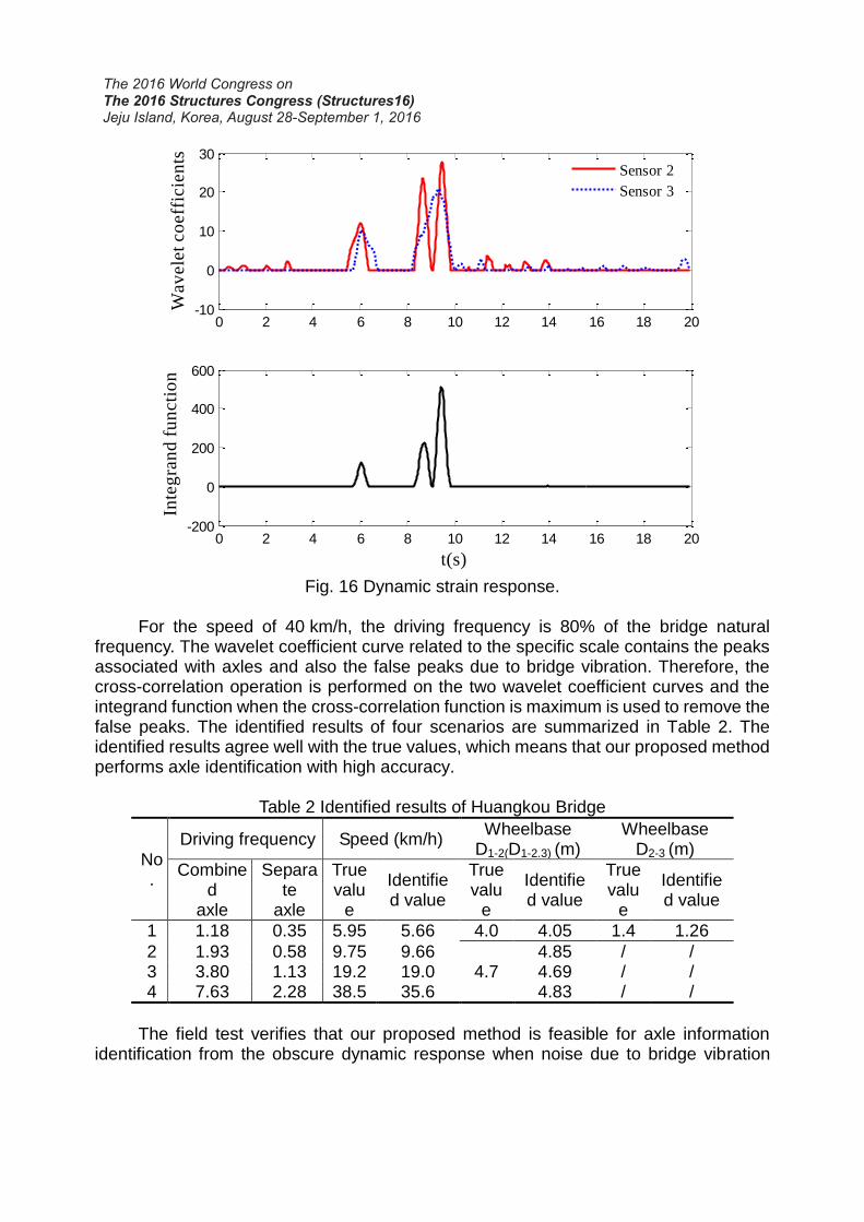
For the speed of 40 km/h, the driving frequency is 80% of the bridge natural frequency. The wavelet coefficient curve related to the specific scale contains the peaks associated with axles and also the false peaks due to bridge vibration. Therefore, the cross-correlation operation is performed on the two wavelet coefficient curves and the integrand function when the cross-correlation function is maximum is used to remove the false peaks. The identified results of four scenarios are summarized in Table 2. The identified results agree well with the true values, which means that our proposed method performs axle identification with high accuracy.
Table 2 Identified results of Huangkou Bridge
No.
Driving frequency Speed (km/h) Wheelbase
D1-2(D1-2.3) (m) Wheelbase
D2-3 (m)
Combined
axle
Separate
axle
True valu
e
Identified value
True valu
e
Identified value
True valu
e
Identified value
1 1.18 0.35 5.95 5.66 4.0 4.05 1.4 1.26
2 1.93 0.58 9.75 9.66 4.7
4.85 / / 3 3.80 1.13 19.2 19.0 4.69 / / 4 7.63 2.28 38.5 35.6 4.83 / /
The field test verifies that our proposed method is feasible for axle information identification from the obscure dynamic response when noise due to bridge vibration

exists. Therefore, this study can enlarge the application range of BWIM and increase the accuracy as well.
6 CONCLUSIIONS
This work proposed a new approach for extracting the axle information of BWIM. The proposed approach is based on wavelet transform, and the wavelet coefficient curve of dynamic response for axle identification is the surrogate. The concept of driving frequency is introduced and is used to select the wavelet scale. The relationship between the driving frequency and axle information is studied, and then an automatic axle information identification method is proposed. This method obtains a reasonable wavelet coefficient curve that corresponds to the specific wavelet scale through iterative computing, as well as avoids subjective selection. The cross-correlation of the wavelet coefficients on two points of different sections is analyzed, and the integrand function that corresponds to the maximum value of the cross-correlation function is used to identify the peaks caused by axles. This function eliminates the false peaks due to the interference caused by the bridge vibration and extracts axle information from obscure dynamic response. A numerical simulation of axle information identification and a full-scale study case of a vehicle passing through a simply supported bridge are used to illustrate the procedure of the proposed method. The feasibility of identifying the axle information from obscure dynamic response of beam structures is verified. The proposed method is also proven to decrease the sensitivity requirement of the structural components of a bridge that uses BWIM, thereby expanding its application range.
7 REFERENCES
Bakht, B., Mufti, A., Jaeger, L.G. (2009), “Bridge weighing-in-motion systems and their use in SHM of bridges”, Proceeding of the 4th International Conference on Structural Health Monitoring of Intelligent Infrastructure. Zurich, Switzerland.
Chatterjee, P., et al. (2006), “Wavelet Domain Analysis for Identification of Vehicle Axles from Bridge Measurements.” Computers and Structures, Vol.84, 1792-1801.
European Commission. (2001), “Weight-in-motion of axles and vehicles for Europe(WAVE)”, General Report, Paris: LCPC.
European Commission. (2001), “Weight-in-motion of axles and vehicles for Europe(WAVE)”, Report of Work Package 1.2-Bridge WIM Systems, Dublin: University College Dublin.
Hitchcock, W.A., Salama, T., Zhao, H., Callahan, D., Toutanji, H., Richardson, J., & Jackson, J. (2011), “Expanding Portable BWIM Technology”, UTCA Project No. 08204, Tuscaloosa, AL, USA.
Hitchcock, W.A., Uddin, N., Sisiopiku, V., Salama, T., Kirby, J., Zhao, H., Richardson, J. (2012), “Bridge Weigh-in-Motion (BWIM) System Testing and Evaluation”, UTCA Project No. 07212, Tuscaloosa, AL, USA.
ISO 8608. (1995), “Mechanical vibration-Road surface profiles-reporting of measured

data”.
Kobayashi, Y., Miki, C., Tanabe, A. (2004), “Longterm monitoring of traffic loads by automaticreal timeweigh in motio.” Journal of Structural Mechanics and Earthquake Engineering,Vol.69(773), 99-111.
Lechner, B., et al. (2010), “A Wavelet-Based Bridge Weigh-in-Motion System.” International Journal on Smart Sensing and Intelligent Systems , Vol.3(4), 573-591.
Lydon, Myra, Taylor, S.E.,Robinson, D.,Mufti, A., O’Brien, E.J. (2016), “Rencent development in bridge weigh in motion(B-WIM).” Journal of Civil Structural Health Monitoring, Vol.6, 69-81.
Mcnulty, P., O’Brien, E.J. (2003), “Testing of bridge weigh-inmotion system in a sub-Arctic climate.” Journal of Testing and Evaluation, Vol.31(6), 497–506.
Moses, F. (1979), “Weigh-in-motion system using instrumented bridges.” Transportation Engineering Journal (ASCE), Vol.105(3), 233-249.
Navid, Z., et al. (2013), “Identification of Truck Types using Strain Sensors include Co-located Strain Gauges”, Structures Congress, 363-375.
O’Brien, E.J., Znidaric, A., Ojio, T. (2008), “Bridge weigh-in-motion: Latest developments and applications worldwide”, Proceeding of the International conference on heavy vehicles incorporating heavy vehicle transport technology and weigh-in-motion (pp. 25– 38), Paris, France.
Quilligan, M., Karoumi, R., O’Brien, E.J. (2002), “Development and testing of a 2-dimensional multi-vehicle bridgeWIM algorithm”, Proceeding of the 3rd international conference on weigh-in-motion (ICWIM3) (pp. 199–208). Ames, IA: Iowa State University, Center for Transportation Research and Education.
Sakayabagi, H., et al. (2008), “Analysis of Axle Position Information from Strain History Data with Long Influence Lines.” Journal of Structural Engineering, Vol.54A, 582-589.
Xiao, Z.G., et al. (2006), “Measurement of truck axle weight by instrumenting longitudinal ribs of orthotropic bridge.” Journal of bridge engineering, Vol.11(5),526-532.
Yang, Y.B., Lin, C.W., Yan, J.D. (2004), “Extracting the bridge frequencies from the dynamic response of a passing vehicle.” Journal of Sound and Vibration, Vol.272(3-5), 471-493.
Yang, Y.B., Lin, C.W.(2005), “Vehicle-bridge interaction dynamics and potential applications.” Journal of Sound and Vibration, Vol.284, 205–226.
Yin, X. F., Fang, Z., Cai C.S. (2011), “Lateral vibration of high-pier bridge under moving vehicular loads.” Journal of Bridge Engineering, Vol.16(3),400-412.
Zhu, X.Q., Law, S.S.(2005), “Bridge dynamic responses due to road surface roughness and braking of vehicle.” Journal of Sound and Vibration, Vol.282, 805-830