Embed Size (px)
Citation preview

Watson-Marlow 620UN, 620U, 620SN, 620S User Manual 1
WATSON-MARLOW BREDEL MANUALS
Watson-Marlow 620UN / 620U, 620SN / 620S pumps
m-620un-u-sn-s-gb-01
1 Declaration of conformity 32 Declaration of incorporation 33 Five-year warranty 34 When you unpack your pump 55 Information for returning pumps 66 Peristaltic pumps - an overview 67 Safety notes 78 Pump specifications 9
8.1 Pressure capability 148.2 Dimensions 15
9 Good pump installation practice 169.1 General recommendations 169.2 Do’s and do not’s 17
10 Connecting this product to a power supply 18
11 Start-up check list 1912 Switching the pump on for the
first time 2013 Switching the pump on in
subsequent power cycles (if not in auto-restart mode) 22
14 Manual operation 2314.1 Keypad functions,
620UN, 620U 2314.2 Keypad functions,
620SN, 620S 2514.3 Speed 2814.4 Direction 2814.5 Keypad lock 2814.6 Keypad beep 2814.7 To reset defaults 2914.8 To reset language 2914.9 Backlight 2914.10 Auto-restart 2914.11 Manual operation and
remote digital inputs and outputs 30
15 Main menu 3115.1 Keypad functions in
menu screens 3115.2 Main menu entry 31
16 Setup 3316.1 Trim 3416.2 Analogue 35
16.2.1 Input 1: speed 3616.2.2 Trim 3816.2.3 Menu 38
16.3 Display 3816.4 Outputs 3916.5 Remote stop 4116.6 Auto-restart 4216.7 Set maximum allowed
speed 4316.8 Set minimum allowed
speed 4416.9 Scrolling 4416.10 Date and time 4516.11 Backlight 4616.12 ROM 4616.13 Language 4716.14 Defaults 4716.15 Security code 4816.16 Exit 49
17 MemoDose and calibration 5017.1 Changing dosing speed 5117.2 Footswitch operation and
other remote inputs and outputs with MemoDose 52
17.3 Flow calibration 5217.4 Exit 54
18 Pin out details 5419 Exit 5520 Automatic control wiring
using the 620N module 5620.1 620N module removal
and replacement 5620.2 Wiring up 5720.3 Speed: analogue input 6020.4 Speed: analogue output 6120.5 Tachometer frequency
output 6120.6 Run/stop input 62
Contents

Watson-Marlow 620UN, 620U, 620SN, 620S User Manual 2
20.7 Direction input 6220.8 Auto / manual toggle
input 6220.9 MemoDose input 6320.10 Leak detection input 6320.11 Outputs 1, 2, 3, 4 6420.12 Supply voltages 64
21 Automatic control wiring without the 620N module 6621.1 Speed: analogue input 6721.2 Speed: analogue output 6821.3 Tachometer frequency
output 6821.4 run/stop input 6921.5 Direction input 7021.6 Auto / manual toggle
input 7021.7 MemoDose input 7121.8 Leak detection input 7121.9 Pump status outputs 72
21.9.1 Logic output 1 7221.9.2 Logic output 2 7321.9.3 Logic output 3 7421.9.4 Logic output 4 74
21.10 Supply voltages 7522 Automatic control and operation 7623 Troubleshooting 78
23.1 Error codes 7924 Drive maintenance 8025 Drive spares 8026 620RE MarkII, 620RE4 MarkII and
620R MarkII pumpheads 8126.1 620RE, 620RE4 and 620R
Key safety information 8126.2 620RE, 620RE4 and 620R
safe-guarding 81
26.3 620RE, 620RE4 and 620R pumping conditions 82
26.4 620RE, 620RE4 and 620R pump installation 82
26.5 620RE, 620RE4 and 620R general operation 83
26.6 620RE and 620RE4 tube element loading 84
26.7 620R continuous tube loading 86
26.8 620RE, 620RE4 and 620R tube element or continuous tube removal 87
26.9 620RE, 620RE4 and 620R maintenance 87
26.10 620RE, 620RE4 and 620R CIP and SIP 90
26.11 620RE, 620RE4 and 620R pumphead spares 91
27 620RE, 620RE4 and 620R performance data 9327.1 620RE, 620RE4 and 620R
flow rates 9428 620R tubing product codes 9629 620RE and 620RE4 LoadSure
tube element product codes 9730 620 series pumping accessories 9831 Trademarks 9932 Warning not to use pumps in
patient-connected applications 9933 Publication history 9934 Decontamination certificate 100

Watson-Marlow 620UN, 620U, 620SN, 620S User Manual 3
UN, U, SN, S
UN, U, SN, S
UN, U, SN, S
1 Declaration of conformityThis declaration was issued for Watson-Marlow 620UN, 620U, 620SN and620S pumps on September 19, 2005. When this pump unit is used as astand-alone pump it complies with: Machinery Directive 2006/42/EC, EMCDirective 2004/108/EC.
This pump is ETL listed: ETL control number 3050250. Cert to CAN/CSAstd C22.2 No 61010-1. Conforms to UL std 61010A-1.
See 8 Pump specifications.
2 Declaration of incorporationWhen this pump unit is to be installed into a machine or is to be assembled withother machines for installations, it must not be put into service until the relevantmachinery has been declared in conformity with the Machinery Directive 2006/42.
Responsible person: Christopher Gadsden, Managing Director, Watson-MarlowLimited, Falmouth, Cornwall TR11 4RU, England. Telephone +44 (0) 1326 370370Fax +44 (0) 1326 376009.
The information in this user guide is believed to be correct at the time of publica-tion. However, Watson-Marlow Limited accepts no liability for errors or omissions.Watson-Marlow Bredel has a policy of continuous product improvement, andreserves the right to alter specifications without notice. This manual is intended foruse only with the pump it was issued with. Earlier or later models may differ. Themost up-to-date manuals appear on the Watson-Marlow website:http://www.watson-marlow.com
3 Five-year warranty520 cased pumps, 620 cased pumps and 720 cased pumps
For any 520, 620 or 720 cased pump purchased after 1 January 2007, Watson-Marlow Limited (“Watson-Marlow”) warrants, subject to the conditions and excep-tions below, through either Watson-Marlow, its subsidiaries, or its authorised distrib-utors, to repair or replace free of charge, any part of the product which fails withinfive years of the day of manufacture of the product. Such failure must have occurredbecause of defect in material or workmanship and not as a result of operation of theproduct other than in normal operation as defined in this pump manual.

Watson-Marlow 620UN, 620U, 620SN, 620S User Manual 4
Watson-Marlow shall not be liable for any loss, damage, or expense directly or indi-rectly related to or arising out of the use of its products, including damage or injurycaused to other products, machinery, buildings, or property, and Watson-Marlowshall not be liable for consequential damages, including, without limitation, lost prof-its, loss of time, inconvenience, loss of product being pumped, and loss of produc-tion. This warranty does not obligate Watson-Marlow to bear any costs of removal,installation, transportation, or other charges which may arise in connection with awarranty claim.
Conditions of and specific exceptions to the above warranty are:
Conditions� Products must be returned by pre-arrangement, carriage-paid, to Watson-
Marlow, or a Watson-Marlow approved service centre.� All repairs or modifications must have been made by Watson-Marlow Limited,
or a Watson-Marlow approved service centre or with the express permission ofWatson-Marlow.
� Warranties purporting to be on behalf of Watson-Marlow made by any person,including representatives of Watson-Marlow, its subsidiaries, or its distributors,which do not accord with the terms of this warranty shall not be binding uponWatson-Marlow unless expressly approved in writing by a Director or Managerof Watson-Marlow.
Exceptions� The warranty shall not apply to repairs or service necessitated by normal wear
and tear or for lack of reasonable and proper maintenance.� All tubing and pumping elements as consumable items are excluded.� Products which, in the judgment of Watson-Marlow, have been abused, mis-
used, or subjected to malicious or accidental damage or neglect are excluded.� Electrical surge as a cause of failure is excluded.� Chemical attack is excluded� All pumphead rollers are excluded.� The 620R family of pumpheads are excluded from all warranty when pumping
above 2 bar while above 165rpm.� Pumpheads from the 313/314 and the Microcassette ranges and any 701
extension pumpheads are excluded and retain their one-year standard pump-head warranty. The drive they are attached to is subject to the five-year war-ranty as set out here.
� Ancillaries such as leak detectors are excluded.

Watson-Marlow 620UN, 620U, 620SN, 620S User Manual 5
UN, U, SN, S 4 When you unpack your pumpUnpack all parts carefully, retaining the packaging until you are sure all componentsare present and in good order. Check against the components supplied list, below.
Packaging disposal
Dispose of packaging materials safely, and in accordance with regulations in yourarea. The outer carton is made of corrugated cardboard and can be recycled.
Inspection
Check that all components are present. Inspect components for damage in transit.If anything is missing or damaged, contact your distributor immediately.
Components supplied
620UN, 620U, 620SN and 620S pumps are dedicated to 620R series pumpheads.Pumps are supplied as:
� Dedicated 620R pump drive unit fitted with 620R, 620RE or 620RE4 pumphead(see 8. Pump specifications).
� A 620N module providing pump ingress protection to IP66, NEMA 4X, if a 620UN or 620SN.Note: the module is attached for transit, but must be removed to allow wiringup, voltage selection and fuse inspection and then re-affixed before the pumpis operated.
� The designated mains power lead for your pump � PC-readable CDROM containing these operating instructions � Quick Start manual
Note: Some versions of this product will include components different from thoselisted above. Check against your purchase order.
Storage
This product has an extended shelf life. However, care should be taken after storageto ensure that all parts function correctly. Users should be aware that the pump con-tains a battery with an unused life of seven years. Long-term storage is not recom-mended for peristaltic pump tubing. Please observe the storage recommendationsand use-by dates which apply to tubing you may wish to bring into service after stor-age.
Watson-Marlow 620UN, 620U, 620SN, 620S User Manual 6
UN, U, SN, S
UN, U, SN, S
5 Information for returning pumpsEquipment which has been contaminated with, or exposed to, body fluids, toxicchemicals or any other substance hazardous to health must be decontaminatedbefore it is returned to Watson-Marlow or its distributor.
A certificate included at the rear of these operating instructions, or signed state-ment, must be attached to the outside of the shipping carton. This certificate isrequired even if the pump is unused.
If the pump has been used, the fluids that have been in contact with the pump andthe cleaning procedure must be specified along with a statement that the equipmenthas been decontaminated.
6 Peristaltic pumps - an overviewPeristaltic pumps are the simplest pump, with no valves, seals or glands to clog orcorrode. The fluid contacts only the bore of a tube, eliminating the risk of the pumpcontaminating the fluid, or the fluid contaminating the pump. Peristaltic pumps canrun dry.
How they work
A compressible tube is squeezed between a roller and a track on an arc of a circle,creating a seal at the point of contact. As the roller advances along the tube, theseal also advances. After the roller has passed, the tube returns to its original shape,creating a partial vacuum which is filled by fluid drawn from the inlet port.
Before the roller reaches the end of the track, a second roller compresses the tubeat the start of the track, isolating a packet of fluid between the compression points.As the first roller leaves the track, the second continues to advance, expelling thepacket of fluid through the pump’s discharge port. At the same time, a new partialvacuum is created behind the second roller into which more fluid is drawn from theinlet port.
Backflow and siphoning do not occur, and the pump effectively seals the tube whenit is inactive. No valves are needed.
The principle may be demonstrated by squeezing a soft tube between thumb andfinger and sliding it along: fluid is expelled from one end of the tube while more isdrawn in at the other.
Animal digestive tracts function in a similar way.
Suitable applications
Peristaltic pumping is ideal for most fluids, including viscous, shear-sensitive, corro-sive and abrasive fluids, and those containing suspended solids. They are especial-ly useful for pumping operations where hygiene is important.
Peristaltic pumps operate on the positive displacement principle. They are particu-larly suitable for metering, dosing and dispensing applications. Pumps are easy toinstall, simple to operate and inexpensive to maintain.

Watson-Marlow 620UN, 620U, 620SN, 620S User Manual 7
7 Safety notesIn the interests of safety, this pump and the tubing selected should only be used bycompetent, suitably trained personnel after they have read and understood thismanual, and considered any hazard involved. If the pump is used in a manner notspecified by Watson-Marlow Ltd, the protection provided by the pump may beimpaired.
This symbol, used on the pump and in this manual,means: Caution, refer to accompanying documents.
This symbol, used on the pump and in this manual,means: Do not allow fingers to contact moving parts.
There is a user-replaceable type T5A H 250V fusein the fuseholder in the centre of the switchplateat the back of the pump. The 620N module must
be removed, if a 620DiN, to allow access to the switchplate.See 20.1 620N module removal and replacement. There arethermal fuses within the pump which self-reset within 60 sec-onds; if they trip an error code is displayed. This pump containsno user-serviceable fuses or parts.
This symbol, used on the pump and in this manual,means: Recycle this product under the terms of the EUWaste Electrical and Electronic Equipment (WEEE)Directive.
Fundamental work with regard to lifting, trans-portation, installation, starting-up, maintenanceand repair should be performed by qualified per-
sonnel only. The unit must be isolated from mains power whilework is being carried out.
UN, U, SN, S

Watson-Marlow 620UN, 620U, 620SN, 620S User Manual 8
Any person who is involved in the installation or periodic maintenance of this equip-ment should be suitably skilled or instructed and supervised using a safe system ofwork. In the UK this person should also be familiar with the Health and Safety atWork Act 1974.
There are moving parts inside the pumphead. Before opening the tool-unlockable pumphead guard, ensure that the following safety directions are fol-lowed.
� Ensure that the pump is isolated from the mains power. � Ensure that there is no pressure in the pipeline. � If a tube failure has occurred, ensure that any fluid in the pumphead has been
allowed to drain to a suitable vessel, container or drain. � Ensure that protective clothing and eye protection are worn if hazardous fluids
are pumped. � Primary operator protection from rotating parts of the pump is provided by the
pumphead safeguard. Note that safeguards differ, depending on the type ofpumphead. See the pumphead section of this manual: 26.
� Secondary operator protection from rotating parts of the pump is provided byelectrical interlocking of the pumphead guard. This function will stop the pumpif the guard is inadvertently opened while the pump is running. For details ofpermissible pumphead orientations, see the pumphead section of this manual:26.
This product does not comply with the ATEX directiveand must not be used in explosive atmospheres.
This pump must be used only for its intended purpose. The pump must be accessi-ble at all times to facilitate operation and maintenance. Access points must not beobstructed or blocked. The pump’s mains plug is the disconnecting device (for iso-lating the motor drive from the mains supply in an emergency). Do not position thepump so that it is difficult to disconnect the mains plug. Do not fit any devices to thedrive unit other than those tested and approved by Watson-Marlow. Doing so couldlead to injury to persons or damage to property for which no liability can be accept-ed.
If hazardous fluids are to be pumped, safety procedures specific to the particularfluid and application must be put in place to protect against injury to persons.
The exterior surfaces of the pump may get hot during operation. Do not take holdof the pump while it is running. Let it cool after use before handling it.
No attempt should me made to run the drive without a pumphead fitted.
The pump weighs more than 18kg (the exact weight depends on model and pump-head—see 8 Pump specifications). Lifting should be performed according to standardHealth and Safety guidelines. Finger recesses are built into the sides of the lowershell for convenience in lifting; in addition, the pump can conveniently be lifted bygrasping the pumphead and (where fitted) the 620N module at the rear of the pump.

Watson-Marlow 620UN, 620U, 620SN, 620S User Manual 9
UN, SN
UN, U, SN, S
8 Pump specificationsLabels fixed to the rear of the pump contain manufacturer and contact details, prod-uct reference number, serial number and model details.
The same information is carried on the drive’s backplate, accessible when the 620Nmodule is removed. The picture below is how a 620SN looks from the box. The num-ber of connectors varies according to the model.

Watson-Marlow 620UN, 620U, 620SN, 620S User Manual 10
UN, U 620UN, IP66 NEMA 4X model, and 620U, IP31 model
This pump can be controlled from the keypad or remotely. It features:
Manual control Speed adjustment; run and stop; direction control; "max" key for rapid prim-ing.
Remote controlThe pump can be digitally controlled with a contact closure or logic input signalto operate the pump.
Analogue control The pump speed can be controlled through an analogue signal input in theranges 0-10V, 1-5V or 4-20mA.
OutputsA 0-10V, 4-20mA or 0-1258Hz output signal provides feedback of the pumpspeed. There are four digital (620U) or relay (620UN) status outputs which canbe configured in software for a variety of pump parameters.
MemoDose Allows precise repeat dosing. Stores in memory a pulse count from the motor.This count is repeated each time START is pressed to provide a single-shotdose.
CalibrationUses the same pulse count as MemoDose. The corresponding pumped volumecan be entered to calibrate the flow of the pump.
Guard switchPrimary operator protection from rotating parts of the pump is provided by thefixed guard. Secondary operator protection from rotating parts of the pump isprovided by indicator-only switching of the pumphead guard.
620SN, IP66 NEMA 4X model, and 620S, IP31 model
This pump operates by manual control only. There are no external control connec-tions. All pump functions are controlled from the keypad. It features:
Manual control Speed adjustment; run and stop; direction control; "max" key for rapid prim-ing.
MemoDose Allows precise repeat dosing. Stores in memory a pulse count from the motor.This count is repeated each time START is pressed to provide a single-shotdose.
CalibrationUses the same pulse count as MemoDose. The corresponding pumped volumecan be entered to calibrate the flow of the pump.
Guard switchPrimary operator protection from rotating parts of the pump is provided by thefixed guard. Secondary operator protection from rotating parts of the pump isprovided by indicator-only switching of the pumphead guard.
SN, S

Watson-Marlow 620UN, 620U, 620SN, 620S User Manual 11
UN, U, SN, S IP (Ingress Protection) and NEMA definitions
IPNEMA
1st Digit 2nd Digit
3
Protected againstingress of solid objectswith a diameter ofmore than 2.5mm.Tools, wires etc with athickness of more than2.5mm are preventedfrom approach
1
Protection against dripping water fallingvertically. No harmfuleffect must be produced
2
Indoor use to provide adegree of protectionagainst limitedamounts of fallingwater and dirt
5
Protected againstharmful dust deposits.Ingress of dust is nottotally prevented butthe dust must notenter in sufficientquantity to interferewith satisfactory operation of the equipment. Completeprotection against contact
5
Protection againstwater projected from anozzle against theequipment (enclosure)from any direction.There must be noharmful effect (waterjet)
12
Indoor use to provide adegree of protectionagainst dust, fallingdirt and dripping, non-corrosive liquids
13
Indoor use to provide adegree of protectionagainst dust andspraying of water, oiland non-corrosivecoolants
6
Protection againstingress of dust (dust-tight). Complete protection against contact
6
Protection againstheavy seas or powerfulwater jets. Water mustnot enter the equipment (enclosure)in harmful quantities(splashing over)
4X
Indoor or outdoor use*to provide a degree ofprotection againstsplashing water, wind-blown dust and rain,hose-directed water;undamaged by the formation of ice on theenclosure. (Resist corrosion: 200-hoursalt spray)
* 620 cased pumps are rated to NEMA 4X (indoor use) only.
Watson-Marlow 620UN, 620U, 620SN, 620S User Manual 12
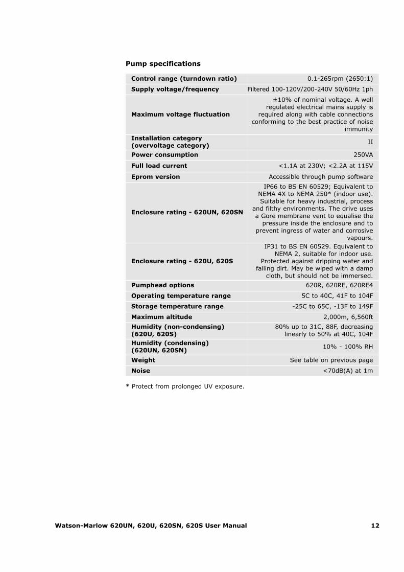
* Protect from prolonged UV exposure.
Pump specifications
Control range (turndown ratio) 0.1-265rpm (2650:1)
Supply voltage/frequency Filtered 100-120V/200-240V 50/60Hz 1ph
Maximum voltage fluctuation
±10% of nominal voltage. A well regulated electrical mains supply is
required along with cable connectionsconforming to the best practice of noise
immunity
Installation category (overvoltage category)
II
Power consumption 250VA
Full load current <1.1A at 230V; <2.2A at 115V
Eprom version Accessible through pump software
Enclosure rating - 620UN, 620SN
IP66 to BS EN 60529; Equivalent toNEMA 4X to NEMA 250* (indoor use).Suitable for heavy industrial, process
and filthy environments. The drive usesa Gore membrane vent to equalise the
pressure inside the enclosure and to prevent ingress of water and corrosive
vapours.
Enclosure rating - 620U, 620S
IP31 to BS EN 60529. Equivalent toNEMA 2, suitable for indoor use.
Protected against dripping water andfalling dirt. May be wiped with a damp
cloth, but should not be immersed.
Pumphead options 620R, 620RE, 620RE4
Operating temperature range 5C to 40C, 41F to 104F
Storage temperature range -25C to 65C, -13F to 149F
Maximum altitude 2,000m, 6,560ft
Humidity (non-condensing)(620U, 620S)
80% up to 31C, 88F, decreasing linearly to 50% at 40C, 104F
Humidity (condensing) (620UN, 620SN)
10% - 100% RH
Weight See table on previous page
Noise <70dB(A) at 1m

Watson-Marlow 620UN, 620U, 620SN, 620S User Manual 13
Standards
EC harmonisedstandards
Safety of machinery—electrical equipment of machines: BS EN 60204-1
Safety requirements for electrical equipment for measurement, control and laboratory use:
BS EN 61010-1 incorporating A2 Category 2, Pollution degree 2
Degrees of protection provided by enclosures (IP code): BS EN 60529 amendments 1 and 2
Conducted emissions:BS EN 55011 A1 and A2, Class A, called by BS EN 61000-6-4
Radiated emissions: BS EN 55011 A1 and A2, Class A, called by BS EN 61000-6-4
Electrostatic discharge: BS EN 61000-4-2
Radiated RF immunity:BS EN 61000-4-3 A1 and A2, called by BS EN 61000-6-2
Fast transient burst:BS EN 61000-4-4 A1 and A2, Level 3 (2kV),
called by BS EN 61000-6-2
Surge immunity:BS EN 61000-4-5 A1 and A2, called by BS EN 61000-6-2
Conducted RF immunity:BS EN 61000-4-6, called by BS EN 61000-6-2
Voltage dips and interruptions:BS EN 61000-4-11, called by BS EN 61000-6-2
Mains harmonics: BS EN 61000-3-2 A2
Pumps and pump units for liquids—common safety requirements: BS EN 809
Other standards
UL 61010A-1
CAN/CSA-C22.2 No 61010-1
Conducted emissions FCC 47CFR, Part 15.107
Radiated emissions FCC 47CFR, Part 15
NEMA 4X to NEMA 250 (indoor use) for IP66 products only

Watson-Marlow 620UN, 620U, 620SN, 620S User Manual 14
8.1 Pressure capability0-4 bar higher pressure pumping
This pump’s default running speed is 165rpm. It can be run at any speed up to265rpm. Please note, however:� The 620RE and 620RE4 rotor warranty is limited to 2 bar from 165rpm
to 265rpm.� A warning is displayed when the user sets the speed above 165rpm.
Note: Applies to 620RE MarkII and 620RE4 MarkII pumpheads only. � The pump’s software records the duration of operation above 165rpm.
0-2 bar pressure pumping

Watson-Marlow 620UN, 620U, 620SN, 620S User Manual 15
8.2 Dimensions
Unit weights
Drive only + 620R, 620RE + 620RE4
IP31 16.5kg, 36lb 6oz 19.6kg, 43lb 3oz 20.1kg, 44lb 5oz
IP66 NEMA 4X 17.4kg, 38lb 6oz 20.5kg, 45lb 3oz 21.0kg, 46lb 5oz

Watson-Marlow 620UN, 620U, 620SN, 620S User Manual 16
UN, U, SN, S 9 Good pump installation practice
9.1 General recommendationsPosition
A correctly engineered installation will promote long tube life. Site the pump on aflat, horizontal, rigid surface, free from excessive vibration, to ensure correct lubri-cation of the gearbox. Allow a flow of air around the pump to ensure that heat canbe dissipated. Ensure that the temperature around the pump does not exceed 40C.
Do not stack other 620 pumps on top of this pump. It is, however, acceptable tostack other equipment on the upper surface of the 620 (as long as the ambient tem-perature does not exceed 40C).
Emergency disconnection
The pump’s mains plug is the disconnecting device (for isolating the motor drivefrom the mains supply in an emergency). Do not position the pump so that it is dif-ficult to disconnect the mains plug. The STOP key on the keypad will always stopthe pump. However, it is recommended that a suitable local emergency stop deviceis fitted into the mains supply to the pump.
Valves
Peristaltic pumps are self-priming and self-sealing against backflow. No valves arerequired in inlet or discharge lines. Valves in the process flow must be opened beforethe pump operates. Users are advised to fit a pressure relief device between thepump and any valve on the discharge side of the pump to protect against damagecaused by accidental operation with the discharge valve closed.
The pump may be set up so that the direction of rotor rotation is clockwise or count-er-clockwise, whichever is convenient.
Tubing materials: run-in advice
Sta-Pure, Chem-Sure and Marprene TM tubing are hard to compress when new.When using tubing made of these materials, the first five pumphead revolutionsshould be at a speed of 10rpm or greater. If the pump is run slower, the safety system built into pump drive’s software may cause it to stop and display an over-current error message.
Pressure advice
In most circumstances, rotor and tube life are maximised if the pumphead is runslowly, particularly when pumping at high pressure. However, to maintain performance at pressures above 2 bar, avoid running the pumphead below 50rpm.If low-flow, high-pressure operation is necessary, switching to a smaller tube is recommended.

Watson-Marlow 620UN, 620U, 620SN, 620S User Manual 17
9.2 Do’s and do not’sDo not build a pump into a tight location without adequate airflow around the pump.
Do ensure that when the 620N watertight module is fitted the seals are intact andproperly located. Ensure that the holes for cable glands are properly sealed to main-tain the IP66 / NEMA 4X rating.
Do not strap the control and mains power cables together.
Do keep delivery and suction tubes as short and direct as possible - though ideallynot shorter than 1m - and follow the straightest route. Use bends of large radius: atleast four times the tubing diameter. Ensure that connecting pipework and fittingsare suitably rated to handle the predicted pipeline pressure. Avoid pipe reducers andlengths of smaller bore tubing than the pumphead section, particularly in pipelineson the suction side. Any valves in the pipeline (not usually needed) must not restrictthe flow. Any valves in the flow line must be open when the pump is running.
Do use suction and delivery pipes equal to or larger than the bore of the tube in thepumphead. When pumping viscous fluids use pipe runs with a bore several timeslarger than the pump tube.
Do ensure that on longer tube runs at least 1m of smooth bore flexible tubing is con-nected to the inlet and discharge port of the pumphead to help to minimize impulselosses and pulsation in the pipeline. This is especially important with viscous fluidsand when connecting to rigid pipework.
Do site the pump at or just below the level of the fluid to be pumped if possible.This will ensure flooded suction and maximum pumping efficiency.
Do keep the pumphead track and all moving parts clean and free from contamina-tion and debris.
Do run at slow speed when pumping viscous fluids (though see Pressure advice in9.1 General recommendations). Flooded suction will enhance pumping performancein all cases, particularly for materials of a viscous nature.
Do recalibrate after changing pump tubes, fluid, or any connecting pipework. It isalso recommended that the pump is recalibrated periodically to maintain accuracy.
IP66 / NEMA 4X models may be hosed down, but should not be immersed. Protectfrom prolonged UV exposure.
IP31 models may be wiped with a damp cloth, but should not be hosed orimmersed. The front of IP31 models is further protected against light spillages ontothe pump.
When using Marprene or Bioprene continuous tubing, do re-tension the tubeafter the first 30 minutes of running.
Tube selection: The chemical compatibility lists published in Watson-Marlow pub-lications are guides. If in doubt about the compatibility of a tube material and theduty fluid, request a Watson-Marlow tube sample card for immersion trials.

Watson-Marlow 620UN, 620U, 620SN, 620S User Manual 18
UN, U, SN, S
UN, SN
10 Connecting this product to a power supplyA well regulated electrical mains supply is required along with cable connectionsconforming to the best practice of noise immunity. It is not recommended to sitethese drives alongside “dirty” electrical mains supplies such as 3-phase contactors and inductive heaters without special attention being paid to unacceptable mains-borne noise.
The voltage selector is mounted in the switchplate atthe rear of the pump, protected from water by the620N module (620DuN). The module must beremoved to allow access to the switchplate. See 20.1620N module removal and replacement. Set thevoltage selector to 115V for 100-120V 50/60Hz supplies or 230V for 200-240V 50/60Hz supplies.Always check the voltage selector switch before con-necting the mains supply. Make suitable connectionto an earthed, single-phase mains electricity supply.
We recommend using commer-cially available supply voltagesurge suppression where there
is excessive electrical noise.
Power cable: The pump is supplied fitted with either of two cable glands andapproximately 2.8m of power cable. The European cable is to Harmonised codeH05RN-F3G0.75, used with our gland part number SL0128 which is suitable for anoutside cable sheath diameter of 4-7mm. The north American cable is to typeSJTOW 105C 3-18AWG VW-1 used with our gland part number SL0123 which is suit-able for an outside cable sheath diameter of 7-9mm.
Power cables of NEMA 4X specification pumps are fitted with a standard US mainspower plug. IP66 specification pumps are supplied with no plug. Wiring a mains plugmust only be undertaken by suitably skilled, qualified personnel.
Conductor coding
European North American
line brown black
neutral blue white
ground green/yellow green

Watson-Marlow 620UN, 620U, 620SN, 620S User Manual 19
UN, U, SN, S
UN, SN The voltage selector switch is not visible while the620N module is in place. Do not switch the pump onunless you have checked that it is set to suit yourpower supply by removing the module and inspecting
the switch, and then refitting the module. See 20.1 620N module removal and replacement.
If the mains power cable is inappropriate for your installation, it can be changed.Please contact your local Watson-Marlow Bredel service centre.
Input line fusing: type T5A H 250V20mm time-delayed cartridge fuse,located in a fuseholder in the centre ofthe switchplate at the rear of the pump.
Power interruption: This pump has anauto-restart feature which, when active,will restore the pump to the operatingstate it was in when power was lost. See16.6 Auto-restart.
Stop / start power cycles: Do notpower up/power down for more than100 starts per hour, whether manuallyor by means of the auto-restart facility.We recommend remote control where ahigh number of starts is required.
11 Start-up check listNote: See also 26.6 and 26.7 Tube loading.
� Ensure that proper connections are achieved between the pump tube and suc-tion and discharge piping.
� Ensure proper connection has been made to a suitable power supply. � Ensure that the recommendations in section 9. Good pump installation practice
are followed.
UN, U, SN, S

Watson-Marlow 620UN, 620U, 620SN, 620S User Manual 20
UN, U, SN, S 12 Switching the pump on for the first timeNote: This manual uses bold type to highlight the active option in menu screens:“English” in the first screen represented here. The active option appears on thepump display in inverse text.
� Switch on the power supply at the rear of the pump. The pump runs a power-on test to confirm proper functioning of the memory and hardware. If a fault isfound, an error message is displayed. See 23.1 Error codes.
� The pump displays a language menu. Use the UP and DOWN keys to selectyour language. Press the ENTER key to confirm your choice.
� The information which follows assumes that your choice was English.� When the language is chosen this menu will not appear again and all menus
will appear in the language you chose. (Language can be reset as describedlater. See 16.13 Language.)
� The pump displays the Watson-Marlow start-up screen for four seconds, fol-lowed by the pump model identity screen for four seconds (an example isshown here), and then the manual mode main screen.
� The rotation symbol on the display indicates clockwise rotation. The defaultspeed setting is 165rpm, but 265rpm is available (see 16.7 Set maximumallowed speed). Other initial start-up operational parameters are listed in thetable below.
Watson-Marlow 620UN, 620U, 620SN, 620S User Manual 21
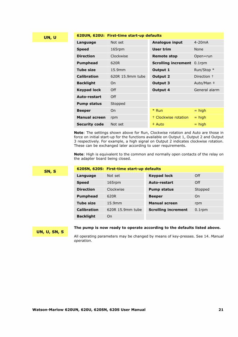
UN, U 620UN, 620U: First-time start-up defaults
Language Not set Analogue input 4-20mA
Speed 165rpm User trim None
Direction Clockwise Remote stop Open=run
Pumphead 620R Scrolling increment 0.1rpm
Tube size 15.9mm Output 1 Run/Stop *
Calibration 620R 15.9mm tube Output 2 Direction †
Backlight On Output 3 Auto/Man ‡
Keypad lock Off Output 4 General alarm
Auto-restart Off
Pump status Stopped
Beeper On * Run = high
Manual screen rpm † Clockwise rotation = high
Security code Not set ‡ Auto = high
Note: The settings shown above for Run, Clockwise rotation and Auto are those inforce on initial start-up for the functions available on Output 1, Output 2 and Output3 respectively. For example, a high signal on Output 2 indicates clockwise rotation.These can be exchanged later according to user requirements.
Note: High is equivalent to the common and normally open contacts of the relay onthe adapter board being closed.
620SN, 620S: First-time start-up defaults
Language Not set Keypad lock Off
Speed 165rpm Auto-restart Off
Direction Clockwise Pump status Stopped
Pumphead 620R Beeper On
Tube size 15.9mm Manual screen rpm
Calibration 620R 15.9mm tube Scrolling increment 0.1rpm
Backlight On
SN, S
UN, U, SN, SThe pump is now ready to operate according to the defaults listed above.
All operating parameters may be changed by means of key-presses. See 14. Manualoperation.

Watson-Marlow 620UN, 620U, 620SN, 620S User Manual 22
13 Switching the pump on in subsequent power cycles (if not in auto-restart mode)
UN, U, SN, S
� Switch on the power supply at the rear of the pump. The pump runs a power-on test to confirm proper functioning of the memory and hardware. If a fault isfound, an error message is displayed. See 23.1 Error codes.
� The pump displays the Watson-Marlow start-up screen for four seconds fol-lowed by the pump model identity screen for four seconds (an example isshown here), and then the manual mode main screen.
� Note: Once in the manual mode main screen, keys assume their normal func-tions - see 15.1 Keypad in menu screens below. A subsequent press on STARTcauses the pump to operate.
� Start-up defaults are those in place when the pump was switched off last.Check that the pump is set to operate as you require it.
The pump is now ready to operate.
All operating parameters may be changed by means of key-presses. See 14. Manualoperation below.
Watson-Marlow 620UN, 620U, 620SN, 620S User Manual 23
14 Manual operation
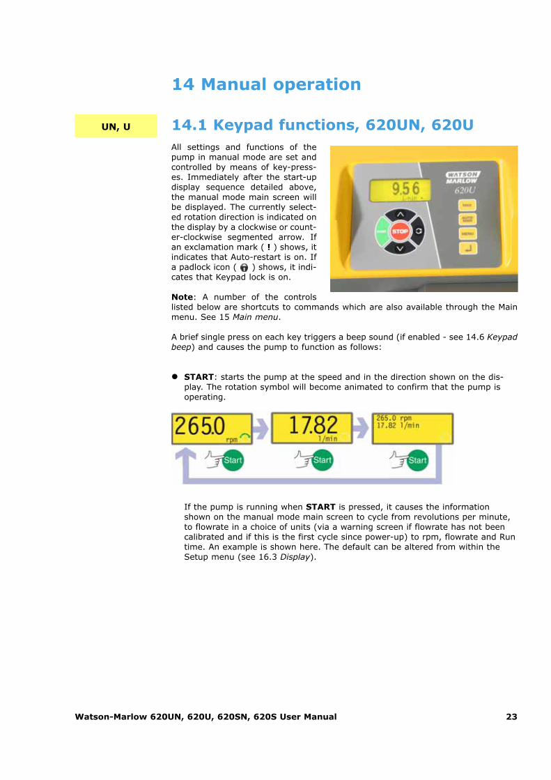
14.1 Keypad functions, 620UN, 620UAll settings and functions of thepump in manual mode are set andcontrolled by means of key-press-es. Immediately after the start-updisplay sequence detailed above,the manual mode main screen willbe displayed. The currently select-ed rotation direction is indicated onthe display by a clockwise or count-er-clockwise segmented arrow. Ifan exclamation mark ( ! ) shows, itindicates that Auto-restart is on. Ifa padlock icon ( ) shows, it indi-cates that Keypad lock is on.
Note: A number of the controlslisted below are shortcuts to commands which are also available through the Mainmenu. See 15 Main menu.
A brief single press on each key triggers a beep sound (if enabled - see 14.6 Keypadbeep) and causes the pump to function as follows:
� START: starts the pump at the speed and in the direction shown on the dis-play. The rotation symbol will become animated to confirm that the pump isoperating.
UN, U
If the pump is running when START is pressed, it causes the informationshown on the manual mode main screen to cycle from revolutions per minute,to flowrate in a choice of units (via a warning screen if flowrate has not beencalibrated and if this is the first cycle since power-up) to rpm, flowrate and Runtime. An example is shown here. The default can be altered from within theSetup menu (see 16.3 Display).
Watson-Marlow 620UN, 620U, 620SN, 620S User Manual 24
� MAX: while pressed, MAX operates the pump at the maximum allowed speedand in the direction shown on the display. When released, the pump returns toits previous status.Note: Priming can be achieved by pressing the MAX key until fluid flowsthrough the pump and reaches the point of discharge, and then releasing theMAX key.
� AUTO/MAN: toggles the pump into analogue control. When started, the pumpruns at the speed set by any analogue signal applied to the pump, and in thedirection shown in the display.
� STOP: if the pump is running, pressing STOP stops the pump. The display willcontinue to show the previous speed and direction. The pump will return to thisspeed and direction when the START key is pressed again.
� UP: increases the speed shown on the display in minimum steps of 0.1rpm, orother steps as pre-selected in the Scrolling section of the Setup menu, (unlessthe speed displayed is already the maximum allowed speed). If the pump isthen started by pressing the START key, it will operate at the new speed. Ifthe pump is running when UP in pressed, the change takes effect immediately. Note: If the pump’s flow rate has been calibrated (see 17.3 Calibration), aftera speed change a screen showing the new rpm figure and the new flowrate isdisplayed for four seconds before returning the user to the previously set man-ual mode main screen: rpm or flowrate.
� DOWN: decreases the speed shown on the display in minimum steps of0.1rpm, or other steps as pre-selected in the Scrolling section of the Setupmenu. If the pump is then started by pressing the START key, it operates atthe new speed. The minimum speed possible is 0.1rpm. If the pump is runningwhen DOWN is pressed, the change takes effect immediately. Note: If the pump’s flow rate has been calibrated (see 17.3 Calibration), aftera speed change a screen showing the new rpm figure and the new flowrate isdisplayed for four seconds before returning the user to the previously set man-ual mode main screen: rpm or flowrate. Note: You can reduce the pump speed from 0.1rpm (or any other minimumdisplayed unit of speed as selected in the Scrolling section of the Setup menu)to 0rpm by a further press on the DOWN key. The pump is still in the runningstate and the rotation symbol will continue to move. Press the UP key to returnthe pump to the minimum speed. Note: If a minimum allowed speed has been set in the Set Min Speed sectionof the Setup menu, the above note on speed reduction to 0rpm does not apply.
� DIRECTION: toggles the direction of rotation shown on the display. If thepump is then started by pressing the START key, it rotates in the new direc-tion. If the pump is running when DIRECTION is pressed, the change takeseffect immediately.
� ENTER: is used to enter/confirm numeric and menu selections. Also cycles theinformation shown on the manual mode main screen exactly as START does,whether the pump is running or not. See START, above.
� MENU: causes the main menu to be displayed, from which all aspects of pumpsetup can be controlled, including the MemoDose facility. See 15. Main menu.
Watson-Marlow 620UN, 620U, 620SN, 620S User Manual 25
Keypress combinations cause the pump to function as follows:
Note: A number of the controls listed below are shortcuts to commands which arealso available through the Main menu. See 15. Main menu.
� UP and DIRECTION on power-up: toggles the keypad beep on and off. � START on power-up: switches on the Auto-restart facility. See 16.6 Auto-
restart. � STOP on power-up: switches off the Auto-restart facility. See 16.6 Auto-
restart. � STOP and DIRECTION on power-up: allows the user to press UP and DOWN
keys to toggle the sense of remote run/stop control between open=stop andopen=run.
� STOP and UP while the pump is stopped: turns the display backlight on. � STOP and DOWN while the pump is stopped: turns the display backlight off. � MAX and UP: sets the pump to maximum allowed speed. � MAX and DOWN: sets the pump to minimum allowed speed. � DIRECTION and DOWN: interrupts the display to show the pump’s ROM ver-
sion for four seconds.� START pressed and held for two seconds: toggles the keypad lock on and off.
Only the START and STOP keys are active when keypad lock is on. The pad-lock icon is displayed.
� STOP pressed and held for two seconds: toggles the keypad lock on and off.Only the START and STOP keys are active when keypad lock is on. The pad-lock icon is displayed.
� STOP STOP within half a second: shortcut entry to the MemoDose menu;when in MemoDose, shortcut return to manual mode main screen. See 17.MemoDose.
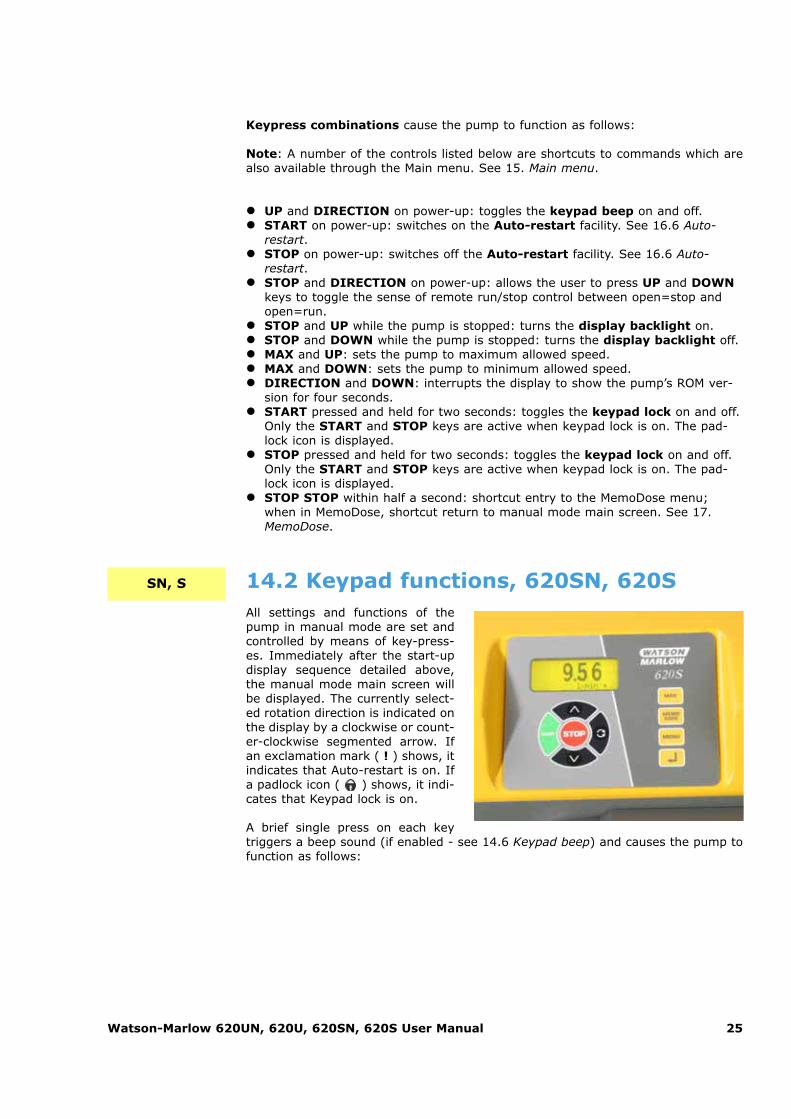
14.2 Keypad functions, 620SN, 620SAll settings and functions of thepump in manual mode are set andcontrolled by means of key-press-es. Immediately after the start-updisplay sequence detailed above,the manual mode main screen willbe displayed. The currently select-ed rotation direction is indicated onthe display by a clockwise or count-er-clockwise segmented arrow. Ifan exclamation mark ( ! ) shows, itindicates that Auto-restart is on. Ifa padlock icon ( ) shows, it indi-cates that Keypad lock is on.
A brief single press on each keytriggers a beep sound (if enabled - see 14.6 Keypad beep) and causes the pump tofunction as follows:
SN, S

Watson-Marlow 620UN, 620U, 620SN, 620S User Manual 26
� START: starts the pump at the speed and in the direction shown on the dis-play. The rotation symbol will become animated to confirm that the pump isoperating.
If the pump is running when START is pressed, it causes the informationshown on the manual mode main screen to cycle from revolutions per minute,to flowrate in millilitres per minute (via a warning screen if flowrate has notbeen calibrated and if this is the first cycle since power-up) to rpm andflowrate. An example is shown here.
� MAX: while pressed, MAX operates the pump at the maximum allowed speedand in the direction shown on the display. When released, the pump returns toits previous status.Note: Priming can be achieved by pressing the MAX key until fluid flowsthrough the pump and reaches the point of discharge, and then releasing theMAX key.
� STOP: if the pump is running, pressing STOP stops the pump. The display willcontinue to show the previous speed and direction. The pump will return to thisspeed and direction when the START key is pressed again. STOP is also used in the MemoDose facility, while calibrating the pump, andsetting the maximum speed.
� UP: increases the speed shown on the display in minimum steps of 0.1rpm, orother steps as pre-selected in the Scrolling section of the Setup menu, (unlessthe speed displayed is already the maximum allowed speed). If the pump isthen started by pressing the START key, it will operate at the new speed. Ifthe pump is running when UP in pressed, the change takes effect immediately. Note: If the pump’s flow rate has been calibrated (see 17.3 Calibration), aftera speed change a screen showing the new rpm figure and the new flowrate isdisplayed for four seconds before returning the user to the previously set man-ual mode main screen: rpm or flowrate.
� DOWN: decreases the speed shown on the display in minimum steps of0.1rpm, or other steps as pre-selected in the Scrolling section of the Setupmenu. If the pump is then started by pressing the START key, it operates atthe new speed. The minimum speed possible is 0.1rpm. If the pump is runningwhen DOWN is pressed, the change takes effect immediately. Note: If the pump’s flow rate has been calibrated (see 17.3 Calibration), aftera speed change a screen showing the new rpm figure and the new flowrate isdisplayed for four seconds before returning the user to the previously set man-ual mode main screen: rpm or flowrate. Note: You can reduce the pump speed from 0.1rpm (or any other minimumdisplayed unit of speed as selected in the Scrolling section of the Setup menu)to 0rpm by a further press on the DOWN key. The pump is still in the runningstate and the rotation symbol will continue to move. Press the UP key to returnthe pump to the minimum speed. Note: If a minimum allowed speed has been set in the Set Min Speed sectionof the Setup menu, the above note on speed reduction to 0rpm does not apply.

Watson-Marlow 620UN, 620U, 620SN, 620S User Manual 27
� DIRECTION: toggles the direction of rotation shown on the display. If thepump is then started by pressing the START key, it rotates in the new direc-tion. If the pump is running when DIRECTION is pressed, the change takeseffect immediately.
� ENTER: is used to enter/confirm numeric and menu selections. Also cycles theinformation shown on the manual mode main screen exactly as START does,whether the pump is running or not. See START, above.
� MENU: causes the main menu to be displayed, from which pump Setup andMemoDose can be controlled. See 15. Main menu.
� MEMODOSE: causes the MemoDose facility to be displayed. See 17.MemoDose.
Keypress combinations cause the pump to function as follows:
� DIRECTION on power-up: resets defaults. � UP and DIRECTION on power-up: toggles the keypad beep on and off. � START on power-up: switches on the Auto-restart facility. See 16.6 Auto-
restart. � STOP on power-up: switches off the Auto-restart facility. See 16.6 Auto-
restart. � STOP and UP while the pump is stopped: turns the display backlight on. � STOP and DOWN while the pump is stopped: turns the display backlight off. � DIRECTION and DOWN: interrupts the display to show the pump’s ROM ver-
sion for four seconds.� MAX and UP: sets the pump to maximum allowed speed.� MAX and DOWN: sets the pump to minimum allowed speed.� START pressed and held for two seconds: toggles the keypad lock on and off.
Only the START and STOP keys are active when keypad lock is on. The pad-lock icon is displayed.
� STOP pressed and held for two seconds: toggles the keypad lock on and off.Only the START and STOP keys are active when keypad lock is on. The pad-lock icon is displayed.
� STOP STOP within half a second: shortcut entry to the MemoDose menu;when in MemoDose, shortcut return to manual mode main screen. See 17.MemoDose.

Watson-Marlow 620UN, 620U, 620SN, 620S User Manual 28
14.3 SpeedTo change the running speed:
� Use the UP and DOWN keys to change the pump’s running speed within limitsof the minimum allowed speed and the maximum allowed speed. The minimumspeed possible is 0.1rpm.Note: You can reduce the pump speed from 0.1 rpm to 0 rpm by a furtherpress on the DOWN key. The pump is still in the running state and the rotationsymbol will continue to move. Press the UP key to return the pump to the min-imum speed.
Note: The maximum allowed speed of the drive defaults to 165rpm. It is possibleto set this limit at any speed up to 265rpm. See 16.7 Set maximum allowed speed,and section 3 Five-year warranty.
14.4 DirectionTo toggle the pump’s rotation sense:
� Press DIRECTION to toggle the pump between clockwise and counter-clock-wise rotation. Note: Direction control is available subject to access not being limited by security
code. See 16.15 Security code.
14.5 Keypad lockThe keypad can be locked to prevent changes to pump speed or other settings, andmake it possible only to start or stop the pump. The padlock symbol shows on thedisplay.
� While the pump is running, hold down the START key for two seconds. Thepadlock symbol shows and only the START and STOP keys function.
� The keypad may also be locked while the pump is stopped. Hold down theSTOP key for two seconds. The padlock symbol shows and only the STARTand STOP keys function.
� To unlock the keypad while the pump is running hold down the START key fortwo seconds. The padlock symbol is removed. If the pump is stopped holddown the STOP key until the padlock symbol is removed.
Note: Keypad lock is available subject to access not being limited by securitycode. See 16.15 Security code.
14.6 Keypad beepThe pump keypad can operate silently or indicate a positive key-press with a beepsound.
� To toggle the sound on and off, stop the pump. Turn off the mains power switchat the rear of the pump.
� Depress the UP and DIRECTION keys while switching on the mains powerswitch at the rear of the pump.
UN, U, SN, S
Watson-Marlow 620UN, 620U, 620SN, 620S User Manual 29
14.7 To reset defaultsAll settings can be re-set to factory defaults. � Turn off the mains power switch at the rear of the pump. � Press the DIRECTION key while switching on the mains power switch at the
rear of the pump. A warning screen is displayed briefly, followed by a screenasking the user to confirm that factory defaults are to be reset.
� Select Yes or No using the UP and DOWN keys. Confirm by pressing ENTER.If Yes was confirmed, the pump resets all user-settable data to default valuesand displays the manual mode main screen. If No was confirmed, no change ismade and the manual mode main screen is displayed.
The language of display screens may be reset only by resetting defaults.
14.8 To reset languageThe language of display screens is set on initial start-up. To reset language, reset alldefaults (see 14.7 To reset defaults).
14.9 BacklightTo turn the display backlight on: � Depress the STOP and UP keys together.
To turn the display backlight off: � Depress the STOP and DOWN keys together.
See 16.11 Backlight.
14.10 Auto-restartThis pump offers an auto-restart feature. When active on power loss, it will restorethe pump when power returns to the operating state it was in when power was lost.It does not operate when powering down in the middle of a dose; when the pump isrestarted, it will await a press on the START key to begin the interrupted doseagain. Auto-restart is retained while the pump is switched off. When the pump startsrunning look for the ! symbol on the display. This ! symbol indicates that the pumpis set for auto-restart.
Do not use auto-restart for more than 100 starts perhour. We recommend remote control where a high num-ber of starts is required.
Watson-Marlow 620UN, 620U, 620SN, 620S User Manual 30
To turn the auto-restart facility on:
� Turn off the mains power switch at the rear of the pump. � Depress the START key while switching on the mains power switch at the rear
of the pump.
To turn the auto-restart facility off:
� Turn off the mains power switch at the rear of the pump. � Depress the STOP key while switching on the mains power switch at the rear
of the pump.
14.11 Manual operation and remote digital inputs and outputsThe remote run / stop, direction and leak-detected inputs are operational.
The remote status outputs are all fully functional.
The STOP key acts as an overriding emergency stop. The run / stop input will notstart the pump in manual mode, but once the START key has been pressed, theremote run / stop input will stop and start the pump according to its operationalstate.
(620UN) If you invert the operation of the remote run / stop switch to operate asopen=stop, you must connect pin 7 to 19, lower D-connector, to be able to startthe pump from the keypad. See 20.6 Run/stop injput.
(620U) If you invert the operation of the remote run / stop switch to operate asopen=stop, you must connect pin 7 to 19, lower D-connector, to be able to startthe pump from the keypad. See 20.6 Run/stop injput.
If STOP is pressed the remote run / stop switch will have no effect.
You cannot invert the remote direction signal.
UN, U

Watson-Marlow 620UN, 620U, 620SN, 620S User Manual 31
15 Main menu
15.1 Keypad functions in menu screensIn addition to their functions in other operations, the following keys have specificactions in menu screens:
� STOP: In general, STOP functions as a "go back" key, taking the user up onemenu level without making a change.
� UP: The UP key is used in menu item selection: it moves a highlight up themenu. When a numerical entry screen is displayed, pressing UP increases thenumber displayed.
� DOWN: The DOWN key is used in menu item selection: it moves a highlightdown a menu. When a numerical entry screen is displayed, pressing DOWNdecreases the number displayed.
� ENTER: The ENTER key functions in a similar way to the "enter" key of a per-sonal computer: it confirms key-presses made immediately before. In menuitem selection, it triggers the action or display selected from a menu using theUP and DOWN keys.
Note: Confirmation screens are displayed for 4 seconds. While they are displayed,a single press on any key removes them.
15.2 Main menu entryThe MENU key displays the main menu and stops the pump if it is running in man-ual mode. It operates at any point in the pump’s activity except where error screensare displayed, or where UP and DOWN keys are used to enter values.
UN, U, SN, S
UN, U
The main menu offers four options: Setup, MemoDose, Pin out details, and Exit.Use the UP and DOWN keys to make a choice. Press the ENTER key to confirm yourdecision.

Watson-Marlow 620UN, 620U, 620SN, 620S User Manual 32
Setup
Setup allows the user to set the pump’s operating parameters under 16 headings:Trim, Analogue, Display, Outputs, Remote stop, Auto-restart, Set max speed, Setmin speed, Scrolling, Date/time, Backlight, ROM, Language, Defaults, Beep, Securitycode and Exit.
MemoDose
The MemoDose facility is used to remember the number of revolutions needed todispense a previously dispensed volume of fluid, and cause the pump to dispensethat volume repeatedly. DOWN keys to make a choice. Press the ENTER key to con-firm your decision.
Pin out details
Selecting Pin out details causes the pump to display an information screen andthen its preset pin and voltage details under 18 headings: Analogue input, Analogueoutput, Tacho output, Run/Stop input, Direction enable input, Direction input, Leakinput, Auto/Man toggle input, Dose input, Output 1, Output 2, Output 3, Output 4,Supply voltages, 0 volts availability, Functional earth, Others and Exit.
Pin out information is not relevant to the 620UN IP66/NEMA 4X pumps. SelectingPin out details causes the pump to display a warning screen and redisplay the mainmenu.
Exit
If Exit is selected, the pump returns to its last manual state with the pump stopped.
U
UN
UN, U
SN, S
The main menu offers three options: Setup, MemoDose and Exit. Use the UP andDOWN keys to make a choice. Press the ENTER key to confirm your decision.
Setup
Setup allows the user to set the pump’s operating parameters under 7 headings:Set max speed, Set min speed, Scrolling, Date/time, ROM, Defaults and Exit.
MemoDose
The MemoDose facility is used to remember the number of revolutions needed todispense a previously dispensed volume of fluid, and cause the pump to dispensethat volume repeatedly.
Exit
If Exit is selected, the pump returns to its last manual state with the pump stopped.

Watson-Marlow 620UN, 620U, 620SN, 620S User Manual 33
UN, U, SN, S 16 SetupEntry to the Setup menu is from the Main menu and can be limited to users whocorrectly enter a three-digit security code. If a security code has been set, selectingSetup and confirming with the ENTER key causes the pump to display the Securitycode entry sequence. See 16.15 Security code. If no security code has been set, thepump displays the first of seven screens containing the Setup menu.
The Setup menu
The Setup menu occu-pies five screens(620UN, 620U) or twoscreens (620SN, 620S).The first two of the620UN and 620U areshown here.
To move from onescreen to subsequent screens, repeatedly press DOWN. Each item ishighlighted in turn until the last item on the screen is highlighted.
A further press on the DOWN key displays the next screen of themenu, with the first item highlighted.
Follow the reverse procedure using the UP key to move to an item ona previous screen of the menu.
Make a selection using the UP or DOWN keys and press ENTER to confirm yourchoice.

Watson-Marlow 620UN, 620U, 620SN, 620S User Manual 34
16.1 Trim
UN
When the pump is under remote control, it tracks an analogue signal from the user’sremote control system to the i/p terminal of the Analogue 1 connectors at the rearof the pump within the ranges 4-20mA, 0-10V or 1-5V. The Trim setup sequenceallows the user to customise the process-signal-to-pump-speed calibration. Thesequence may be entered directly from the Setup menu or from the Analogue setupmenu.
U
When the pump is under remote control, it tracks an analogue signal from the user’sremote control system to pin 4 of the lower D-connector at the rear of the pumpwithin the ranges 4-20mA, 0-10V or 1-5V. The Trim setup sequence allows the userto customise the process-signal-to-pump-speed calibration. The sequence may beentered directly from the Setup menu or from the Analogue setup menu.

Watson-Marlow 620UN, 620U, 620SN, 620S User Manual 35
UN, U � Select Trim from the Setup menu or the Analogue setup menu using the UP orDOWN keys and press ENTER to confirm your choice.
� Apply the low process analogue signal to (620UN) the i/p terminal of theAnalogue 1 connector or (620U) pin 4 of the lower D-connector as instructedin the display. See 16.2 Analogue. While the signal is being applied, pressENTER to record the signal as a calibration point.
� Apply the maximum process control signal. While the signal is being applied,press ENTER to record the signal as a calibration point.
� Apply 50% of the maximum process control signal. While the signal is beingapplied, press ENTER to record the signal as a calibration point.
� If a mistake is made, press STOP at any point in the sequence, and the pumpdisplays the previous screen.
� The final press on ENTER causes the pump to display a confirmation screenand then redisplay the screen from which it entered the trim sequence: theSetup menu or the Analogue setup menu.
The pump calculates a linear response from low to mid and from mid to high, andrecords the results as a new analogue input calibration graph.
If any of the three signals match, a warning screen is displayed before the confir-mation screen appears, and the trim is ignored.
Note: By applying the maximum process control signal when the minimum isrequested and vice versa, inverted responses can be set up.
Note: Resetting factory defaults clears the trim calibration values.
16.2 AnalogueWhen the pump is under remote control, it tracks an analogue signal from the user’sremote control system to the i/p terminal of the Analogue 1 connector at the rearof the pump within the ranges 4-20mA, 0-10V or 1-5V. The Analogue option in theSetup menu allows the user to configure the pump to operate with his remote con-trol system.
When the pump is under remote control, it tracks an analogue signal from the user’sremote control system to pin 4 of the lower D-connector at the rear of the pumpwithin the ranges 4-20mA, 0-10V or 1-5V. The Analogue option in the Setup menuallows the user to configure the pump to operate with his remote control system.
UN, U
U
� Select Analogue from the Setup menu using the UP or DOWN keys and pressENTER to confirm your choice.
� Three options are displayed: Input, Trim and Menu.
UN, U

Watson-Marlow 620UN, 620U, 620SN, 620S User Manual 36
Input allows the user to tell the pump which signal type he will apply, or to choosethe program option. If he selects Program from the subsequent menu, the user canchoose his input type and tell the pump the speeds at which to operate on receiv-ing a low or high process control signal. See 16.2.1 Input 1: speed.
Trim displays the Trim menu, described above. See 16.1 Trim.
Menu returns the user to the first section of the Setup menu. See 16 Setup.
16.2.1 Input 1: speed
� Select Input using the UP or DOWN keys and press ENTER to confirm yourchoice.
� The pump offers three further choices: 4-20mA, 0-10V and 1-5V. Use the UPor DOWN keys to make a selection and press ENTER to confirm your decision.
� The pump configures the hardware and factory-set response data and brieflydisplays a confirmation screen. The user is returned to the Analogue setup dis-play. Example figures are shown here.
� Alternatively the user can select Program to configure the pump to respond ina user-programmed way to any process signal range within within 4-20mA, 0-10V or 1-5V.
UN, U

Watson-Marlow 620UN, 620U, 620SN, 620S User Manual 37
Program
� Select Program using the UP or DOWN keys and press ENTER to confirm. � The pump offers two choices: mA and V (0-10V). Use the UP or DOWN
keys to make a selection and press ENTER to confirm your decision.
� The pump displays a screen allowing you to set the speed for low signalinput (4mA or 0V). Use the UP and DOWN keys to scroll the display to yourchosen speed and press ENTER to confirm the figure.
� The pump displays a screen allowing you to set the speed for high signalinput (20mA or 10V). Use the UP and DOWN keys to scroll the display toyour chosen speed and press ENTER to confirm the figure.
� If a mistake is made, the user may press STOP at any point in thesequence (before pressing ENTER on the high signal speed screen), and thepump displays the previous screen.
� The final press on ENTER causes the pump to configure the hardware andprogrammed response data. It briefly displays a confirmation screen and awarning that the analogue signal is not trimmed, and returns the user to theAnalogue setup menu. Example values are shown here.
Watson-Marlow 620UN, 620U, 620SN, 620S User Manual 38
UN, U
UN, U
UN, U 16.2.2 TrimTrim displays the Trim menu, described above. See 16.1 Trim. It is recommendedthat a trim calibration is always performed to align the pump’s response to the actu-al process analogue signal.
16.2.3 MenuMenu returns the user to the first section of the Setup menu, described above. See16 Setup.
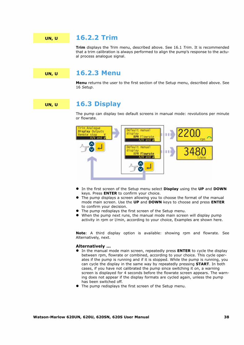
16.3 DisplayThe pump can display two default screens in manual mode: revolutions per minuteor flowrate.
� In the first screen of the Setup menu select Display using the UP and DOWNkeys. Press ENTER to confirm your choice.
� The pump displays a screen allowing you to choose the format of the manualmode main screen. Use the UP and DOWN keys to choose and press ENTERto confirm your decision.
� The pump redisplays the first screen of the Setup menu. � When the pump next runs, the manual mode main screen will display pump
activity in rpm or l/min, according to your choice, Examples are shown here.
Note: A third display option is available: showing rpm and flowrate. SeeAlternatively, next.
Alternatively ... � In the manual mode main screen, repeatedly press ENTER to cycle the display
between rpm, flowrate or combined, according to your choice. This cycle oper-ates if the pump is running and if it is stopped. While the pump is running, youcan cycle the display in the same way by repeatedly pressing START. In bothcases, if you have not calibrated the pump since switching it on, a warningscreen is displayed for 4 seconds before the flowrate screen appears. The warn-ing does not appear if the display formats are cycled again, unless the pumphas been switched off.
� The pump redisplays the first screen of the Setup menu.

Watson-Marlow 620UN, 620U, 620SN, 620S User Manual 39
16.4 OutputsThe 620UN pump offers four relay status outputs. See 12 Switching the pump on forthe first time for initial start-up defaults. Each of six parameters can be configuredto any output, or more than one output.
The 620U pump offers four digital status outputs. See 12 Switching the pump on forthe first time for initial start-up defaults. Each of six parameters can be configuredto any output, or more than one output.
The parameters are:
Run/stopProvides a status output to indicate whether the pumphead is in a running orstopped condition. When running at 0rpm, the run/stop output indicates run-ning.
DirectionProvides a status output to indicate which direction the pump is set to run in.
Auto / manProvides a status output to indicate whether the pump is in analogue controlmode or manual control mode.
General alarmProvides an alarm output when any system error condition occurs except: leakdetected; analogue signal out of range; analogue over-signal; analogue no sig-nal.
Leak detectedWhen used with a leak detector, this output provides an alarm when the pumphas been automatically switched off following tube failure.
HeadProvides an alarm when the pumphead guard is open. If it is running, thepump will stop.
Outputs 1-4 are available as single-pole change-over relay contacts: Relay 1, 2, 3and 4. Connect to the normally open or normally closed contacts of the relay asrequired and configure the pump’s software accordingly. See below in this section.
Note: The maximum rating on the relay contacts of this pump is 30VDC; maximumload 30W.
Output 1 and output 2 are available in two formats: � From pins 10 and 11, lower D-connector, as 5V TTL signals. � From pins 10 and 11, upper D-connector, as open collector logic outputs.
Output 3 and output 4 provide open collector logic outputs from pins 13 and 12,upper D-connector, respectively.
A supply voltage from the pump (5V, 10V, 12V) or user-supplied up to 30V to pin22, upper D-connector, provides the voltage level for these logic status outputs.
UN
UN, U
UN
U
U

Watson-Marlow 620UN, 620U, 620SN, 620S User Manual 40
UN, U
� In the first screen of the Setup menu select Outputs using the UP and DOWNkeys. Press ENTER to confirm your choice.
� The pump displays a screen allowing you to configure each of the four outputs,or to exit this menu. Use the UP and DOWN keys to choose and press ENTERto confirm your decision.
� If Output 1 is chosen, the pump displays the six options. � Selecting General, Leak or Head using the UP and DOWN keys and con-
firming the choice by pressing ENTER configures that option to Output 1,displays a confirmation screen, and returns the user to the Output selectionscreen.
� Selecting Run/Stop, Direction or Auto/Man using the UP and DOWNkeys and confirming the choice by pressing ENTER displays screens allowingthe user to configure Run to High or Low, Clockwise to High or Low, andAuto to High or Low respectively. Choose using the UP and DOWN keysand press ENTER to confirm. The option chosen is configured to Output 1.The pump displays a confirmation screen, and returns the user to theOutput selection screen.
� The user can configure Output 2, Output 3 and Output 4 in the same way, orchoose Exit.
� If STOP is pressed during configuration, the previous setting for the output isretained and the pump redisplays the Output selection screen.
� If Exit is chosen, the pump returns the user to the third screen of the Setupmenu.

Watson-Marlow 620UN, 620U, 620SN, 620S User Manual 41
16.5 Remote stop
The 620UN pump can be started and stopped with a remote switch between the 5Vterminal and the i/p terminal of the Run/stop input, using an open=run oropen=stop command sense. It also operates with a logic input between 5V and 24Von the i/p terminal of the Run/stop input. If remote switching is disabled, neither theremote run/stop nor direction signal inputs will affect the pump state.
The 620U pump can be started and stopped with a remote switch between pin 7 andpin 19 using an open=run or open=stop command sense. It also operates with alogic input between 5V and 24V on pin 7. If remote switching is disabled, neither theremote run/stop nor direction signal inputs will affect the pump state.
UN, U
U
UN
� In the first screen of the Setup menu select Remote stop using the UP andDOWN keys. Press ENTER to confirm your choice.
� The pump displays a screen allowing the user to disable the remote stop fea-ture. Use the UP and DOWN keys to choose Yes or No and press ENTER toconfirm the decision.
� If No is chosen, the pump asks the user to make a further choice, according towhether the pump is required to run on an open or closed remote switch:Open=stop or Open=run. Choose using the UP and DOWN keys and pressENTER to confirm. The pump briefly displays a confirmation screen and returnsthe user to the first screen of the Setup menu.
� If Yes is chosen, the pump briefly displays a confirmation screen and returnsthe user to the first screen of the Setup menu. Example screens are shownhere.
� Note: The confirmation screen indicates whether Remote stop is enabled ordisabled, and displays the command sense of the remote control switch even ifRemote stop has been disabled. This allows the command sense to be dis-played if remote switching is disabled.
Even with the remote stop function disabled, the pumpcould still start if the remote auto/manual toggle inputis used to toggle the pump into analogue mode.

Watson-Marlow 620UN, 620U, 620SN, 620S User Manual 42
Alternatively ...
� To toggle the sense of the remote run/stop control between open=stop andopen=run: stop the pump. Turn off the mains power switch at the rear of thepump.
� Hold down the STOP key and the DIRECTION key, and turn on the mainspower switch.
16.6 Auto-restartThis pump offers an auto-restart feature. If active on power loss, it restores thepump when power returns to the operating state it was in when power was lost. Itdoes not operate when powering down in the middle of a dose: when the pump isrestarted, it will await a press on the START key to begin the interrupted doseagain. Auto-restart is retained while the pump is switched off. When the pump startsrunning, look for the ! symbol on the display. This symbol indicates that the pumpis set for auto-restart.
UN, U
� In the second screen of the Setup menu select Auto-restart using the UP andDOWN keys. Press ENTER to confirm your choice.
� The pump displays a screen allowing the user to activate auto-restart. Use theUP and DOWN keys to choose On or Off and press ENTER to confirm thedecision.
� If Off is chosen, the pump returns the user to the second screen of the Setupmenu. The auto-restart facility will not operate.
� If On is chosen, the pump returns the user to the second screen of the Setupmenu, where an exclamation mark ( ! ) is now visible. This mark confirms thatthe auto-restart feature is in place and will operate the next time power is lostand restored.

Watson-Marlow 620UN, 620U, 620SN, 620S User Manual 43
Alternatively ...
� Stop the pump. Turn off the mains power switch at the rear of the pump. � Hold down the START key and turn on the mains power switch. The ! symbol
shows on the display. � Start the pump. If the mains supply is interrupted the pump will automatically
restart when the mains power returns. � To remove auto-restart switch off the mains power at the rear of the pump.
Hold down the STOP key and turn the mains power switch on. The ! symboldoes not appear.
Do not use auto-restart for more than 100 starts perhour. We recommend remote control where a highnumber of starts is required.
UN, U, SN, S 16.7 Set maximum allowed speedThe maximum allowed speed of the drive defaults to 165rpm. It is possible to setthis limit at any speed down to 1rpm as long as the minumum allowed speed is atleast 1rpm less, or up to 265rpm; however, see 8.1 Pressure capability for use above165rpm.
� In the second screen of the Setup menu select Set max speed using the UPand DOWN keys. Press ENTER to confirm your choice.
� The pump displays a screen allowing the user to set the maximum speed of thepump equal to or lower than the maximum available. Use the UP and DOWNkeys to set the maximum allowed speed and press ENTER to confirm the fig-ure.
� The pump returns the user to the second screen of the Setup menu, via awarning screen requiring the user to press ENTER if he selected a speedgreater than 165rpm.
Note: Maximum allowed speed limits speed under manual or analogue control.

Watson-Marlow 620UN, 620U, 620SN, 620S User Manual 44
16.8 Set minimum allowed speedThe minimum allowed speed of the drive defaults to 0rpm. It is possible to set thislimit at any speed up to 264rpm, as long as the maximum speed is at least 1rpmgreater.
UN, U, SN, S
� In the second screen of the Setup menu select Set min speed using the UPand DOWN keys. Press ENTER to confirm your choice.
� The pump displays a screen allowing the user to set the minimum speed of thepump equal to or higher than the minimum available. Use the UP and DOWNkeys to set the minimum allowed speed and press ENTER to confirm the fig-ure.
� The pump returns the user to the second screen of the Setup menu.
Note: Minimum allowed speed limits speed under manual or analogue control.
16.9 ScrollingIn use, the pump’s speed can be set, up to the maximum allowed speed and downto the minimum allowed speed, by pressing the UP and DOWN keys.
In the Scrolling section of the Setup menu, the UP and DOWN keys allow the speedoptions to be set in increments of the user’s choice: one-tenth of a revolution perminute; one half of a revolution per minute; one, two, five or ten revolutions perminute (or their equivalents in flow rate if the pump has been configured to displayits performance in units of flow). Each press on UP, for example, offers a speed oneincrement greater than the current speed.
Note: For 0.1rpm, 0.5rpm and 1rpm settings, the increments increase progressive-ly as long as the UP or DOWN key is continually held down.
UN, U, SN, S

Watson-Marlow 620UN, 620U, 620SN, 620S User Manual 45
� In the third screen of the Setup menu select Scrolling using the UP andDOWN keys. Press ENTER to confirm your choice.
� The pump displays a screen allowing the user to set the UP and DOWN keys’scrolling increment. Use the UP and DOWN keys to choose 0.1, 0.5, 1.0, 2.0,5.0 or 10.0. Press ENTER to confirm your choice.
� The pump returns the user to the third screen of the Setup menu.
Note: If the maximum allowed speed has been set to a figure which is not a multi-ple of the chosen increment, the last active press on UP raises the speed to thatmaximum rather than to the next multiple of the chosen increment. Similarly, if thepump is running at a speed which is not a multiple of the chosen increment, the firstpress on UP raises the speed to the next multiple of the chosen increment.
16.10 Date and timeThe pump’s real-time clock can be set with the date and time.
UN, U, SN, S
� In the third screen of the Setup menu select Date/time using the UP andDOWN keys. Press ENTER to confirm your choice. The pump displays any pre-vious setting.
� If the setting displayed is correct, press ENTER. The pump redisplays the thirdscreen of the Setup menu.
� If you wish to change the setting, use the UP and DOWN keys to enter thecurrent date (two digits), month (three letters), year (four digits), hour, minuteand second (all two digits), pressing ENTER to confirm each one.
� When ENTER is pressed to confirm the seconds, the pump redisplays the thirdscreen of the Setup menu.

Watson-Marlow 620UN, 620U, 620SN, 620S User Manual 46
UN, U, SN, S
UN, U 16.11 BacklightThe pump’s display can be illuminated or not according to choice.
� In the third screen of the Setup menu select Backlight using the UP andDOWN keys. Press ENTER to confirm your choice.
� The pump displays a screen allowing the user to switch the display backlight onor off. Use the UP and DOWN keys to choose On or Off and press ENTER toconfirm the decision.
� The pump returns the user to the third screen of the Setup menu. The displayis now illuminated or not according to the user’s decision.
Alternatively ... � To turn the backlight off: press STOP and DOWN together. � To turn the backlight on: press STOP and UP together.
16.12 ROMThe pump can display its software version, model number and pump speed.
� In the third screen of the Setup menu select ROM using the UP and DOWNkeys. Press ENTER to confirm your choice.
� The pump displays the software version, model number and the maximum setpump speed for four seconds (an example is shown here), then returns theuser to the third screen of the Setup menu. It also displays a checksum: CHK123, for example. This may be required if reporting pump performance to theWatson-Marlow service department.
Alternatively ...
Press DIRECTION and DOWN together to interrupt the display and show thepump’s ROM version for four seconds.

Watson-Marlow 620UN, 620U, 620SN, 620S User Manual 47
UN, U, SN, S
UN, U 16.13 Language
The pump can be set to operate in several languages.
� In the fourth screen of the Setup menu select Language using the UP andDOWN keys. Press ENTER to confirm your choice.
� In the next screen, choose a language using the UP and DOWN keys. PressENTER to confirm your choice. The pump redisplays the fourth Setup screen inyour chosen language. All screens will subsequently appear in your chosen lan-guage.
16.14 Defaults
All the pump’s user-set data can be reset to factory defaults.
� In the fourth screen of the Setup menu select Defaults using the UP andDOWN keys. Press ENTER to confirm your choice.
� A warning is displayed for four seconds, and the pump asks the user to confirmthat factory defaults are to be reset. Use the UP and DOWN keys to chooseYes if you wish the pump to reset all user-set data back to factory defaults(see 12 Switching the pump on for the first time); or No if you do not wish todo this. Press ENTER to confirm your decision. If Yes was chosen, the pumpresets its factory defaults and redisplays the fourth Setup screen. If No waschosen, the pump makes no changes to its setup and redisplays the fourthSetup screen.

Watson-Marlow 620UN, 620U, 620SN, 620S User Manual 48
UN, U 16.15 Security codeAccess to the pump’s Setup menu can be restricted to those who correctly enter athree-digit security code. See 16 Setup.
The code must first be set.
� In the fourth screen of the Setup menu select Security code using the UP andDOWN keys. Press ENTER to confirm your choice.
� A screen is displayed inviting the user to set a new code or, if a code is alreadyset, cancel it. Use the UP and DOWN keys to choose Set new code or Cancelcode. If no code is in place, no option to cancel a code will be displayed. PressENTER to confirm your decision.
� If Cancel code is chosen, security protection is removed and the user isreturned to the fourth Setup screen.
� If Set new code is chosen, the pump displays a screen with three blankspaces for digits and the instruction "Enter new code". Use the UP and DOWNkeys to make your choice of the digits 0-9 for the first digit. Press ENTER toconfirm. Repeat for the second digit. Repeat for the third digit. The final presson ENTER causes the pump to display a similar three-digit entry screen andthe instruction "Confirm code".
� Repeat the digit-entry sequence.

Watson-Marlow 620UN, 620U, 620SN, 620S User Manual 49
� If the second three-digit code entered differs from the first, the pump willbriefly display an error message and redisplay the first digit-entry screen.
� If the codes tally, the pump will briefly display a confirmation message andredisplay the fourth Setup screen. Access to the Setup menus is now protectedby the new security code.
� If STOP is pressed during code entry, the pump returns the user to the fourthSetup screen. If STOP is pressed during code confirmation, the pump returnsthe user to the first digit-entry screen.
Note: If a code has been set but forgotten, it is still possible to access the Setupscreens to cancel the code or reset it to another three-digit number. Contactyour supplier or Watson-Marlow Technical support for the bypass sequence.
16.16 ExitUN, U, SN, S
� In the fifth screen of the Setup menu Exit is highlighted. Press ENTER. � The user is returned to the main menu.
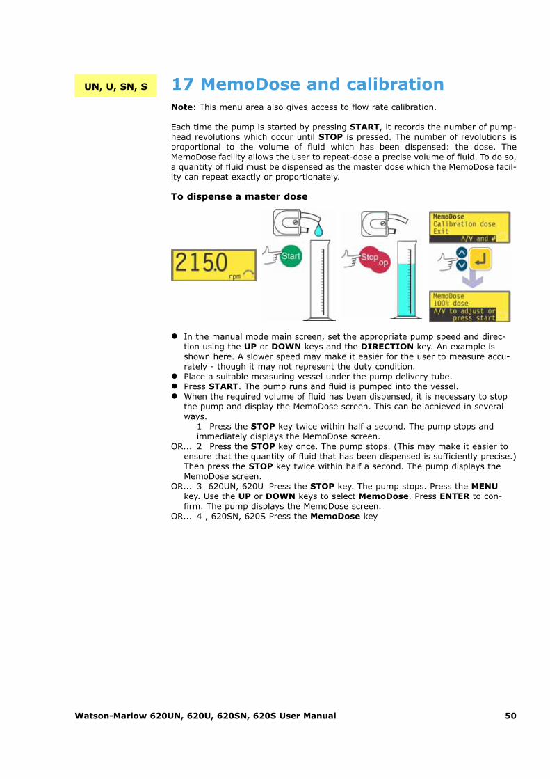
Watson-Marlow 620UN, 620U, 620SN, 620S User Manual 50
� In the manual mode main screen, set the appropriate pump speed and direc-tion using the UP or DOWN keys and the DIRECTION key. An example isshown here. A slower speed may make it easier for the user to measure accu-rately - though it may not represent the duty condition.
� Place a suitable measuring vessel under the pump delivery tube. � Press START. The pump runs and fluid is pumped into the vessel. � When the required volume of fluid has been dispensed, it is necessary to stop
the pump and display the MemoDose screen. This can be achieved in severalways.
1 Press the STOP key twice within half a second. The pump stops andimmediately displays the MemoDose screen.
OR... 2 Press the STOP key once. The pump stops. (This may make it easier toensure that the quantity of fluid that has been dispensed is sufficiently precise.)Then press the STOP key twice within half a second. The pump displays theMemoDose screen.
OR... 3 620UN, 620U Press the STOP key. The pump stops. Press the MENUkey. Use the UP or DOWN keys to select MemoDose. Press ENTER to con-firm. The pump displays the MemoDose screen.
OR... 4 , 620SN, 620S Press the MemoDose key
17 MemoDose and calibrationNote: This menu area also gives access to flow rate calibration.
Each time the pump is started by pressing START, it records the number of pump-head revolutions which occur until STOP is pressed. The number of revolutions isproportional to the volume of fluid which has been dispensed: the dose. TheMemoDose facility allows the user to repeat-dose a precise volume of fluid. To do so,a quantity of fluid must be dispensed as the master dose which the MemoDose facil-ity can repeat exactly or proportionately.
To dispense a master dose
UN, U, SN, S

Watson-Marlow 620UN, 620U, 620SN, 620S User Manual 51
To repeat the dose
� The display counts down as the dose proceeds and stops when the dose iscomplete.
� If STOP is pressed during dosing, the pump stops and returns the user to theMemoDose percentage screen.
Press the STOP key twice within half a second if you wish to exit MemoDose andreturn to manual operation.
17.1 Changing dosing speedThe user must exit MemoDose in order to change pump speed. After returning toMemoDose, the pump dispenses the previous dose size at the new speed.
� Press the STOP key twice within half a second. The pump displays the manualmode main screen.
� Do not start the pump. Doing so erases the previously recorded masterdose and replaces it in the pump’s memory with the current, unmea-sured dose. Adjust the speed showing on the display using the UP or DOWNkeys.
� Press the STOP key twice within half a second to return to MemoDose. The dis-play shows the previous percentage dose size. The pump will dose at the newspeed.
Note: To retain the MemoDose value through a power interruption the pump mustbe in auto-restart mode. The dosing cycle will resume at the start of a dose and waitfor START to be pressed, with the MemoDose percentage screen displayed. See16.6 Auto-restart.
� The pump has recorded thenumber of pumphead revolu-tions required to dispensethe master dose. If the vol-ume of fluid in the measuringvessel is the volumerequired, press START torepeat the dose.
� If the volume of fluid in themeasuring vessel differs fromthe volume required, the per-centage may be adjustedwithin the limits 1% to 999%of the master dose. Use theUP or DOWN keys to alterthe percentage. Press STARTto dispense the new dose.

Watson-Marlow 620UN, 620U, 620SN, 620S User Manual 52
UN, U
UN, U, SN, S
17.2 Footswitch operation and otherremote inputs and outputs withMemoDoseA footswitch can be used to trigger MemoDose dispensing as a hands-free alterna-tive to pressing START.
To operate MemoDose with a footswitch, briefly press the footswitch while theMemoDose percentage screen is displayed.
The remote run/stop input is operational. If a dose is interrupted by a remote stopsignal, the dose will continue from where it stopped when the state is changed torun.
Remote direction control is disabled. The leak-detection input is operational. All sta-tus outputs are operational.
Note: The keypad lock feature is particularly useful to prevent inadvertent dosechanges while using the MemoDose facility. Keypad lock continues to operate inMemoDose if previously enabled; it can also be enabled while in MemoDose mode.See 14.5 Keypad lock.
17.3 Flow calibrationThe pump can display flowrate in millilitres per minute as well as speed in revolu-tions per minute.
� In the manual mode main screen, set the appropriate pump speed and direc-tion using the UP or DOWN keys and the DIRECTION key. A slower speedmay make it easier for the user to measure accurately - though it may not rep-resent the duty condition.
� Place a suitable measuring vessel under the pump delivery tube. � Press START. The pump runs and fluid is pumped into the vessel. The volume
pumped is not important; but the greater the volume, the more accurate theflow-per-revolution calculation will be. We suggest that the pumphead be runfor at least 10 revolutions, and at least 20 when small-bore pumping tube isused.
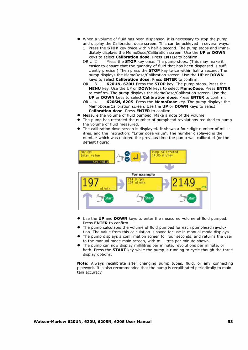
Watson-Marlow 620UN, 620U, 620SN, 620S User Manual 53
� When a volume of fluid has been dispensed, it is necessary to stop the pumpand display the Calibration dose screen. This can be achieved in several ways. 1 Press the STOP key twice within half a second. The pump stops and imme-
diately displays the MemoDose/Calibration screen. Use the UP or DOWNkeys to select Calibration dose. Press ENTER to confirm.
OR... 2 Press the STOP key once. The pump stops. (This may make iteasier to ensure that the quantity of fluid that has been dispensed is suffi-ciently precise.) Then press the STOP key twice within half a second. Thepump displays the MemoDose/Calibration screen. Use the UP or DOWNkeys to select Calibration dose. Press ENTER to confirm.
OR... 3 620UN, 620U Press the STOP key. The pump stops. Press theMENU key. Use the UP or DOWN keys to select MemoDose. Press ENTERto confirm. The pump displays the MemoDose/Calibration screen. Use theUP or DOWN keys to select Calibration dose. Press ENTER to confirm.
OR... 4 620SN, 620S Press the MemoDose key. The pump displays theMemoDose/Calibration screen. Use the UP or DOWN keys to selectCalibration dose. Press ENTER to confirm.
� Measure the volume of fluid pumped. Make a note of the volume. � The pump has recorded the number of pumphead revolutions required to pump
the volume of fluid measured. � The calibration dose screen is displayed. It shows a four-digit number of millil-
itres, and the instruction: "Enter dose value". The number displayed is thenumber which was entered the previous time the pump was calibrated (or thedefault figure).
� Use the UP and DOWN keys to enter the measured volume of fluid pumped.Press ENTER to confirm.
� The pump calculates the volume of fluid pumped for each pumphead revolu-tion. The value from this calculation is saved for use in manual mode displays.
� The pump displays a confirmation screen for four seconds, and returns the userto the manual mode main screen, with millilitres per minute shown.
� The pump can now display millilitres per minute, revolutions per minute, orboth. Press the START key while the pump is running to cycle though the threedisplay options.
Note: Always recalibrate after changing pump tubes, fluid, or any connectingpipework. It is also recommended that the pump is recalibrated periodically to main-tain accuracy.

Watson-Marlow 620UN, 620U, 620SN, 620S User Manual 54
17.4 ExitTo return to the manual mode main screen select Exit using the UP and DOWNkeys. Confirm by pressing STOP.
18 Pin out detailsSelecting Pin out details from the main menu causes the pump to display an infor-mation screen and then its preset pin and voltage details under 17 headings:Analogue input, Analogue output, Tacho output, Run/Stop input, Directionenable input, Direction input, Leak input, Auto/Man toggle, Dose input,Output 1, Output 2, Output 3, Output 4, Supply voltages, 0 volts availabili-ty, Functional earth and Others. No user input is available in this section; it dis-plays information only.
In the main menu, select Pin out details using the UP or DOWN keys and pressENTER to confirm your choice.
U
The Pin out details menu
The Pin out detailsmenu occupies fivescreens. The first twoare shown here.
To move from onescreen to subsequentscreens, repeatedlypress DOWN. Each itemis highlighted in turn until the last item on the screen is highlighted.A further press on the DOWN key displays the next screen of themenu, with the first item highlighted.
Follow the reverse procedure using the UP key to move to an item ona previous screen of the menu.

Watson-Marlow 620UN, 620U, 620SN, 620S User Manual 55
Make a selection using the UP or DOWN keys and press ENTER to confirm yourchoice.
The information on pin outs duplicates the details described in this instruction man-ual under Automatic control wiring.
The screens available are all presented in a similar manner. For example, on select-ing Analogue input, the following screen is displayed:
This indicates that the analogue input signal must be applied to pin 4 of the lowerD-connector at the rear of the pump, where 0 volts is available on pin 16. If the ana-logue input is configured for a 4-20mA signal, the maximum permitted voltage is 5volts; if the analogue input is configured for a 0-10V or 1-5V signal, the maximumpermitted voltage is 10 volts.
The information available on selecting Supply and Others is presented on twoscreens each. Pressing DOWN when the first screen of each is displayed causes thesecond screen to appear. UP performs a similar function.
Pressing STOP or ENTER in any Pin out information screen returns the user to theappropriate Pin out menu screen.
To leave the Pin out menu screens
Cycle through the Pin out menu screens until the fifth screen is displayed. SelectExit using the UP or DOWN keys and press ENTER to confirm your choice.
Alternatively ...
Repeatedly press STOP to go back level by level until the main menu is displayed.
19 ExitPress Exit in the Main menu to return to the Manual mode main screen.
UN, U, SN, S

Watson-Marlow 620UN, 620U, 620SN, 620S User Manual 56
UN 20 Automatic control wiring using the 620N moduleInterfacing the pump with other devices is by means of screw-terminal connectorswithin the 620N watertight module at the rear of the pump. Suitable cable must bepassed into the module through one or more watertight cable glands and connect-ed appropriately. The module must be removed to allow this.
It is important to check that the pump’s voltage set-ting matches the supply. The voltage selection switchis on the rear panel of the drive. The module must beremoved (and replaced) to allow it to be checked.
20.1 620N module removal and replacementTo remove the 620N watertight module:
The module is secured to the back of the drive unit by six M5x12 Pozidriv counter-sunk stainless steel screws.
� Remove the six screws using a suitable crosspoint screwdriver, leaving the topcentre screw till last. Even when all screws have been removed, the sealingstrip may cause the module to adhere to the drive. If so, a gentle tap will freeit. Do not use a tool to lever it off.
� The sealing strip should be retained within its channel on the face of the mod-ule. The transparent on/off switch cover should be retained on its flange on theface of the module. Check the integrity of the seal and the transparent on/offswitch cover. If either is damaged, it must be renewed to maintain ingress pro-tection.
� If necessary, unplug the two 25-way D-connectors linking the module to thepump drive. If necessary, remove the module’s earth link from the back of thedrive. However, the link is long enough to allow the module to fold back to giveaccess to the the circuit board inside and to the back of the drive

Watson-Marlow 620UN, 620U, 620SN, 620S User Manual 57
To replace the 620N watertight module:
� Check that the fuse in the fuseholder (ringed) does not need to be replaced.Check that the voltage selector switch is correctly set.
� Check that the sealing strip is fully in its channel on the face of the module. � Attach the module’s earth link wire. Replace and tighten its screw to 2Nm. � Push home the female (upper) and male 25-way D-connectors. � Hold the module in place. Do not disturb the seal or pinch the earth link wire or
D-connector ribbon cables, and screw in the retaining screws (top centre first).Tighten to 2.5Nm.
Note: The 620N module must be properly fitted using all six screws. Without them,the screw holes may corrode and IP66 (NEMA4X) protection will be compromised.
20.2 Wiring upIt is the user’s responsibility to ensure the pump’s safe and reliable operation underremote and automatic control.
This pump’s 0V lines are commoned and mains transformer-isolated from ground(floating ground). It can be connected to isolated 0V or grounded 0V interfaces.
Cable entry to the module is via up to four watertight cable glands. These may befitted in place of the plugs which seal the module when the pump is shipped.
The number of glands needed depends on thenumber of connection cables required and theconvenience of the installer. As standard, fourM16 cable glands are provided with the pump.
Recommended control cables must be usedfor the terminal blocks: metric = 0.14sq mm- 2.5sq mm solid and 0.14sq mm - 1.5sq mmstranded. USA = 26AWG - 14AWG solid and 26AWG - 16AWG stranded. Cable: cir-cular. Max/min outside diameter to ensure a seal when passed through the standardgland: 9.5mm-5mm. The cable section must be circular to ensure a seal.

Watson-Marlow 620UN, 620U, 620SN, 620S User Manual 58
The recommended cable and cable glands must beused for the IP66 (NEMA 4X) version of this pump; otherwise ingress protection may be jeopardised.
For EMC protection, shielded control cable should be used. The shielding should beterminated to one of the pcb mounting screws or to the adjacent spade connection(where fitted).
For improved EMC protection in extremely noisy environments, shielded cable maybe used in conjunction with watertight EMC metal cable glands. These must beearthed to the module by adding an M16x1.5 nut with serrated edges to ensureproper contact with the inside of the module. It is necessary to remove the module’scircuit board to access the interior of the module: it is held in place by two fixingscrews which can be removed and replaced with a cross-point screwdriver. Take nor-mal anti-static precautions when handling printed circuit boards.
Suitable cables for general-purpose use: 300V with extra premium grade PVC jack-et with good flame and moisture resistance.
Suitable cables for industrial use: 300V extra-rugged polyurethane grade jacket withresistance to oils, fuels, solvents and water.
For convenience of wiring more than 8 conductors per cable may be awkward tohandle. Only two appear in the illustrations here, for clarity.

Watson-Marlow 620UN, 620U, 620SN, 620S User Manual 59
� Use a 19mm spanner to unscrew the sealing plug. Discard the nylon sealingwasher.
� Screw in one of the supplied M16x1.5 cable glands in place of the plug, usingthe new nylon sealing washer supplied. Tighten the gland to 2.5Nm to ensure aseal, using a 21mm spanner. If a different gland is used, it must be watertightto IP66.
� Loosen the gland cap (do not remove it) and pass the cable in through thegland. When it has passed through the gland, continue to push the cablethrough.
� The inside of the module is shaped to guide the cable past the printed circuitboard inside. Continued pushing will feed in enough cable to grip inside themodule with the fingers.
� Pull through sufficient cable to reach the connectors required. Leave a littleslack.
� Strip the outer sheath as necessary and remove 5mm of insulation from theconductors. No tinning or ferrule is required. Note: If very stiff or large-diame-ter cable is used, it may be convenient to strip the outer sheath before passingthe cable’s conductors through the gland. However, to ensure a seal, cable withan undamaged sheath must be present within the gland when it is tightened.
� Twist a suitable length of the cable screen. Loosen one of the pcb retainingscrews and wind the shielding round it. Secure the screen by refastening thescrew. Alternatively, secure the cable screen to the adjacent spade connection(where fitted).
� Push the bared conductor into the square hole in the connector. When the con-ductor is fully in, tighten the retaining screw to hold it in place.
� When all conductors are in position, use a 21mm spanner to tighten the glandcap to 2.5Nm to ensure a seal. Alternatively, tighten the gland by hand until itis finger-tight and use a spanner to tighten it further by one-half a turn.
Do not strap the control and mains power cables together.
620N watertight module pcb connectors:

Watson-Marlow 620UN, 620U, 620SN, 620S User Manual 60
Never apply mains power to the terminals within the620N module. Apply the correct signals to the terminals shown below. Limit signals to the maximumvalues shown. Do not apply voltage across other
terminals. Permanent damage, not covered by warranty, mayresult. The maximum rating on the relay contacts of this pumpis 30V DC; maximum load 30W. Note: Also suitable for lowpower: ie, 1mA at 5VDC minimum.
20.3 Speed: analogue inputIt is possible to control the speed of the pump remotely byone of these methods: a voltage analogue signal within theranges 0-10V or 1-5V; or a current analogue signal withinthe range 4-20mA; or a remote potentiometer using the 10Vsupply at J7.
The analogue process signal must be applied to the i/p ter-minal of the Analogue 1 connector (J5). Ground to the 0Vterminal of the same connector. The pump will provide anincreasing flow rate for a rising control signal (non-invertedresponse) or an increasing flow rate for a falling control sig-nal (inverted response). See 16.2 Analogue in the Setupmenu.
4-20mA circuit impedance: 250Ω.
For voltage modes, a stable, reliable voltage source can be used with a DC voltmeter.Circuit impedance: 22kΩ.
Inverting the response is set up in software. Do not invert the polarity of the termi-nals.
A remote potentiometer withanominal value of between 1k and2k with a minimum of 0.25Wshould be wired between the ter-minals of the Rem-pot connector(J7) and the i/p terminal of theAnalogue 1 connector (J5). When
using a remote potentiometer, do not apply a voltage or cur-rent control input signal at the same time. The speed controlsignal will require calibration relative to the minimum andmaximum settings of the potentiometer. This is done in soft-ware. See 16.1 Trim in the Setup section.
When using a remote potentiometer, it is important to set the analogue input to volt-age in the Setup menu. Otherwise the reference voltage supply from the Rem-potconnector will be overloaded and will not provide a full 5V or 10V.

Watson-Marlow 620UN, 620U, 620SN, 620S User Manual 61
20.4 Speed: analogue outputAn analogue voltage output signal is available onthe Tacho output connector (J11), between the Vterminal and the 0V terminal. The voltage is direct-ly proportional to the pumphead rotation speed.0V = zero speed; 10V = maximum allowed speed.
There is no mA output on this terminal for the620UN. This is available on the 620DuN.
20.5 Tachometer frequency outputA tachometer frequency output is available on the Tacho output connector (J11),between the freq terminal and the 0V terminal. It provides a +5V square wavepulse, maximum 0.5mA, the frequency of which is directly proportional to pumpheadrotation speed. It provides 5.578 Hz/rpm - 334 pulses per output shaft revolution.The pulse train from the pump can be used to calculate the speed of rotation or todetermine the number of pumphead revolutions. This output has the requiredstrength to be effective up to 3m from the pump. Longer cable runs require signalamplification.
Important: general instructions for remote control inputs
All remote control inputs can be wired in two ways:
Logic A logic voltage between 5V TTL and 24V industrial logic may be wiredto the input. The pump is configured to operate without modificationanywhere in this range. Any of the 0V terminals - though preferablythe 0V terminal associated with the desired input - is connected to thecontrol device’s 0V to make the circuit. Low is equivalent to 0V. Highis equivalent to 5V→24V.
SwitchA remote switch may be connected between the input and any posi-tive voltage supply from the pump - though preferably the associatedsupply terminal. Do not use the 10V supply from the Rem-pot connec-tor, however.

Watson-Marlow 620UN, 620U, 620SN, 620S User Manual 62
20.6 Run/stop inputRemote run/stop: connect a remote switch between thei/p terminal and the +5V terminal of the Run/stop i/pconnector (J4). Alternatively a logic input may be appliedto the i/p terminal, ground to the 0V terminal. High inputstops the pump, low input runs the pump. With no connec-tion or with the switch open, the pump will default to run-ning. To change or set the sense of the run/stop input, see16.5 Remote stop in the Setup menu.
20.7 Direction inputTo enable remote direction controland disable the DIRECTION(SHIFT, 1) key on the keypad,link the terminals of the Directionenable link connector (J6).Important: Apply no voltagewhatever to the Directionenable link. Connect a remoteswitch between the +5V terminaland the i/p terminal of theDirection i/p connector (J2). Openswitch for clockwise rotation,
closed switch for counter-clockwise rotation. Alternatively a logic signal may beapplied to the i/p terminal and the 0V terminal of the Direction i/p connector (J2).Low input for clockwise rotation, high input for counter-clockwise rotation. With noconnection the pump defaults to clockwise rotation.
20.8 Auto / manual toggle inputConnect a remote switch between the +5V terminal and thei/p terminal of the Auto-man i/p connector (J1). Closedswitch for automatic control; open switch for manual control.Alternatively a logic input may be applied to the i/pterminal of the Auto-man i/p connector, ground to the 0Vterminal. High input for automatic control; low input for man-ual control.

Watson-Marlow 620UN, 620U, 620SN, 620S User Manual 63
20.9 MemoDose inputConnect a momentary contact switch such as a footswitchor a handswitch between the 5V terminal and the i/p ter-minal of the Dose i/p connector (J3). Close the switch tobegin a dose. This input is software-debounced and func-tions in a similar way to the other remote inputs, such aswith 5V to 24V logic as shown above, using the i/p ter-minal and the 0V terminal. Note: This input is software-debounced, so the signal can be either momentary ormaintained during the dose. If maintained, the signalmust be removed before the next dose.
20.10 Leak detection inputConnect a remote leak-detection device between the +12Vterminal and the i/p terminal on the Tube monitor connector(J9). Closed circuit indicates a leak. Alternatively a logic inputmay be applied to the i/p terminal, ground to the 0V termi-nal. High input indicates a leak. Connect the cable of aWatson-Marlow Tube monitor leak detector as follows:
Tube monitor wire colour 620N module
Blue J9 0V terminal
Yellow J9 i/p terminal
Red J9 +12V terminal
Terminate the screen in the 620N module with a 360° EMC
gland if required. See 20.2 Wiring up.
Note: Use only Watson-Marlow 620 series tube monitors.

Watson-Marlow 620UN, 620U, 620SN, 620S User Manual 64
Important: pump status outputs
Outputs 1-4 are available as single-pole change-over relay contacts:Relay 1, 2, 3 and 4. Connect to the normally open or normally closedcontacts of the relay as required and configure the pump’s softwareaccordingly. See 16.4 Outputs.
Note: The maximum rating on the relay contacts of this pump is 30VDC; maximum load 30W.
Note: Also suitable for low power: ie, 1mA at 5VDC minimum.
20.11 Outputs 1, 2, 3, 4Note: Relay 1 (J14) is represented here. Relay 2, Relay 3and Relay 4 (J15, J16 and J17) function identically.
Connect your output device to the c (common) terminal ofyour chosen relay connector and either the n/c terminal orthe n/o terminal (normally closed or normally open) asrequired. Configure the pump’s software accordingly. See16.4 Outputs.
By default, Relay 1 is configured to indicate Run/Stop status;Relay 2 is configured to indicate Direction status; Relay 3 isconfigured to indicate Auto/man status; Relay 4 is configuredto indicate General alarm status. See 12 Switching the pump on for the first time.
20.12 Supply voltagesAn appropriate voltage supply is available where required on each connector. Inaddition, supplies may be drawn from the Spare supplies connector (J12).
In the table below, "Max load" is the maximum total load on each supply, irrespec-tive of the number of connections.

Watson-Marlow 620UN, 620U, 620SN, 620S User Manual 65
DC VoltageMax
loadTypical use
+5V 10mA
Voltage supply for inputs using
remote switch.
Possible voltage supply for out-
puts if only 5V is required.
+12V 10mA
Possible voltage supply for inputs
using remote switch.
Possible voltage supply for out-
puts. Voltage supply for Watson-
Marlow Tube Monitor leak detec-
tor.
Part voltage supply (-12V also
needed) for the Watson-Marlow
proximity switch.
-12V 10mA
Part voltage supply (+12V also
needed) for the Watson-Marlow
proximity switch.
+10V
(from J7)
Reference voltage for remote
potentiometer speed control. Do
not use as a general supply volt-
age.
Note: All DC supplies are stabilised.

Watson-Marlow 620UN, 620U, 620SN, 620S User Manual 66
U 21 Automatic control wiring without the 620N moduleInterfacing the pump with other devices is by means of three D-connectors at therear of the pump. There are two 25-way D-connectors. The top one is male, thebottom one is female. Mating female and male connectors, screened for EMC com-patibility, must be conventionally soldered to screened control cables.
Recommended control cable: 7 strands 0.2mm, 24AWG, screened, circular, up to 25-core. The cable screen should be earthed either through the functional earth pin onthe D-connector (pin 1 on the upper (male) 25-way D-connector) (pin 13 on thelower (female) 25-way D-connector), or through the metalwork of the socket or plug.
This pump passes all EMC compatibility requirements with up to 25m (82ft) of thecable type specified above. Beyond this distance it is the user’s responsibility toensure the pump’s safe and reliable operation under remote and automatic control.
Do not strap the control and mains power cables together.
The 0V lines on this pump are mains transformer-isolated from ground (floatingground). It can be connected to isolated 0V or grounded 0V interfaces. The TTL(transistor transistor logic) outputs 1 and 2 used here are composed of two states:nominally 0V and 5V; but in practice <0.4V (<16mA) and 2.4-5V (<0.4mA). Theyare not suitable for driving relays. If a relay is to be driven by the TTL signal, it mustbe done as described under Logic output 1-4, below.

Watson-Marlow 620UN, 620U, 620SN, 620S User Manual 67
Never apply mains voltage to the D-connectors. Applythe correct signals to the pins shown. Limit signals tothe maximum values shown. Do not apply voltageacross other pins. Permanent damage, not covered bywarranty, may result.
21.1 Speed: analogue input
It is possible to control the speed of the pump remotely by one of these methods:a voltage analogue signal within the ranges 0-10V or 1-5V; or a current analoguesignal within the range 4-20mA; or a remote potentiometer.
The analogue process signal must be applied to pin 4 of the lower D-connector. 0Vto pin 16. The pump will provide an increasing flow rate for a rising control signal(non-inverted response) or an increasing flow rate for a falling control signal (invert-ed response). See 16.2 Analogue in the Setup menu.
4-20mA circuit impedance: 250Ω.
For voltage modes, a stable, reliable voltage source can be used with a DC voltmeter.Circuit impedance: 22kΩ.
Inverting the response is set up in software. Do not invert the polarity of the pins.
A remote potentiometer with a nominal value of between 1k and 2k with a minimumof 0.25W should be wired as shown. When using a remote potentiometer, do notapply a voltage or current control input signal at the same time. The speed controlsignal will require calibration relative to the minimum and maximum settings of thepotentiometer. This is done in software - see 16.1 Trim in the Setup section.
When using a remote potentiometer, it is important to set the analogue input to volt-age in the Setup menu. Otherwise the reference voltage supply from pin 21 will beoverloaded and will not provide a full 5V or 10V.

Watson-Marlow 620UN, 620U, 620SN, 620S User Manual 68
21.2 Speed: analogue output
An analogue output signal is available as a 0V-10V signal on pin 2 of the lower D-connector. Ground to pin 15. The voltage is fixed and directly proportional to thepumphead rotation speed. 0V = zero speed; 10V = maximum speed.
21.3 Tachometer frequency output
A tachometer frequency output is available on pin 1 of the lower D-connector.Ground to pin 14. It provides a +5V square wave pulse, maximum 0.5mA, the fre-quency of which is directly proportional to pumphead rotation speed. It provides5.578 Hz/rpm - 334 pulses per output shaft revolution. The pulse train from thepump can be used to calculate the speed of rotation or to determine the number ofpumphead revolutions. This output has the required strength to be effective up to3m from the pump. Longer cable runs require signal amplification.

Watson-Marlow 620UN, 620U, 620SN, 620S User Manual 69
Important: general instructions for remote control inputs
All remote control inputs can be wired in two ways:
Logic A logic voltage between 5V TTL and 24V industrial logic may be wiredto the input pin. The pump is configured to operate without modifica-tion anywhere in this range. Any of the 0V pins is connected to thecontrol device’s 0V to make the circuit. One 0V pin is identified in thewiring diagram, but any may be used. Low is equivalent to 0V. Highis equivalent to 5V→24V.
Switch A remote switch may be connected between the input pin and anypositive voltage supply from the pump. One 5V supply pin is identifiedin the wiring diagram but there are several which will do, either 5V orother positive voltage. However, do not use pin 21 on the lower D-connector or pin 20 on the upper D-connector.
21.4 Run/stop input
Remote run/stop: connect a remote switch between pins 7 and 19 of the lower D-connector. Alternatively a logic input may be applied to pin 7 of the lower D-connec-tor, ground to pin 18. High input stops the pump, low input runs the pump. With noconnection or with the switch open, the pump will default to running. To change orset the sense of the run/stop input, see 16.5 Remote stop in the Setup menu.

Watson-Marlow 620UN, 620U, 620SN, 620S User Manual 70
21.5 Direction input
To enable remote direction control and disable the DIRECTION (SHIFT, 1) key onthe keypad, link pins 6 and 18 of the lower D-connector. Connect a remote switchbetween pins 5 and 19 of the lower D-connector. Open switch for clockwise rotation,closed switch for counter-clockwise rotation. Alternatively a logic signal may beapplied to pin 5 of the lower D-connector, ground to pin 17. Low input for clockwiserotation, high input for counter-clockwise rotation. With no connection the pumpdefaults to clockwise rotation.
21.6 Auto / manual toggle input
Connect a remote switch between pins 3 and 18 of the upper D-connector. Closedswitch for automatic control; open switch for manual control. Alternatively a logicinput may be applied to pin 3 of the upper D-connector, ground to pin 16. High inputfor automatic control; low input for manual control.

Watson-Marlow 620UN, 620U, 620SN, 620S User Manual 71
Connect a momentary contact switch such as a footswitch or a handswitch betweenpins 8 and 9 of the lower D-connector. Close the switch to begin a dose. This inputis software-debounced and functions in a similar way to the other remote inputs,such as with 5V to 24V logic as shown above, using pin 8 as the input and pin 20 asthe 0V (lower D-connector). Note: This input is software-debounced, so the signalcan be either momentary or maintained during the dose. If maintained, the signalmust be removed before the next dose.
21.8 Leak detection input
21.7 MemoDose input
Connect a remote leak-detection devicebetween pins 2 and 18 of the upper D-connector. Closed circuit indicates aleak. Alternatively a logic input may beapplied to pin 2 of the upper D-connec-tor, ground to pin 15. High input indicates a leak. Connect a Watson-Marlow leak detector in the same way,drawing 12V to power it from pin 21 of the upper D-connector.
Connect the cable of a Watson-Marlow Tube monitor leak detector as follows:
Tube monitorwire colour
Pin numberupper D-connector
Blue 15
Yellow 2
Red 21
Note: Use only a Watson-Marlow 620 series tube monitor.

Watson-Marlow 620UN, 620U, 620SN, 620S User Manual 72
21.9 Pump status outputsImportant: pump status outputs
All four outputs can be configured in software to output a range ofparameters: see 16.4 Outputs under Setup.
Outputs 1 and 2 are available simultaneously from the upper and lowerD-connectors. The outputs from the lower D-connector operate at 5VTTL only.
All four outputs available from the upper D-connector are open-collec-tor.
By applying a positive voltage to a maximum of 24V to pin 22 of theupper D-connector, all the outputs from this plug are at that voltage:pin 22 is commoned with pins 23, 24 and 25. Care must be taken toensure that the supply voltage has sufficient capability to drive all theloads applied to all outputs used. Important: The total load of thefour logic outputs must not exceed 50mA.
21.9.1 Logic output 1
Output 1 is taken from pin 10 of the upperD-connector, depending on the logic stateof the function assigned to Output 1.Alternatively, a load such as a relay coilmay be connected to pin 10, ground to pin17. Current will flow through the circuitdepending on the logic state of the func-
tion assigned to Output 1. Do not connect to any device requiring more than 50mA.
Additionally, output 1 is available as a 5V TTL logic signal on pin 10 of the lower D-connector. It will change state corresponding to the logic state of the functionassigned to Output 1. Do not connect to any device requiring more than 1 TTL load.
By default, output 1 is configured to indicate Run/Stop status. See 12 Switching thepump on for the first time.

Watson-Marlow 620UN, 620U, 620SN, 620S User Manual 73
21.9.2 Logic output 2
Output 2 is taken from pin 11 of the upper D-connector, depending on the logic stateof the function assigned to Output 2. Alternatively, a load such as a relay coil maybe connected to pin 11, ground to pin 17. Current will flow through the circuitdepending on the logic state of the function assigned to Output 2. Do not connectto any device requiring more than 50mA.
Additionally, output 2 is available as a 5V TTL logic signal on pin 11 of the lower D-connector. It will change state corresponding to the logic state of the functionassigned to Output 2. Do not connect to any device requiring more than 1 TTL load.
By default, output 2 is configured to indicate Direction status. See 12 Switching thepump on for the first time.

Watson-Marlow 620UN, 620U, 620SN, 620S User Manual 74
21.9.3 Logic output 3
Output 3 is taken from pin 13 of the upper D-connector, depending on the logic stateof the function assigned to Output 3. Alternatively, a load such as a relay coil maybe connected to pin 13, ground to pin 17. Current will flow through the circuitdepending on the logic sate of the function assigned to Output 3. Do not connect toany device requiring more than 50mA.
By default, output 3 is configured to indicate Auto/Man status. See 12 Switching thepump on for the first time.
21.9.4 Logic output 4
Output 4 is taken from pin 12 of the upper D-connector, depending on the logic stateof the function assigned to Output 4. Alternatively, a load such as a relay coil maybe connected to pin 12, ground to pin 17. Current will flow through the circuitdepending on the logic state of the function assigned to Output 4. Do not connectto any device requiring more than 50mA.
By default, output 4 is configured to indicate General alarm status. See 12 Switchingthe pump on for the first time.

Watson-Marlow 620UN, 620U, 620SN, 620S User Manual 75
21.10 Supply voltages
In the table below, "Max load" is the maximum total load on each supply irrespec-tive of the number of connections.
Note: All DC supplies are stabilised except the +22.5V.
DCVoltage
Maxload
LowerD
UpperD
Typical use
+5V 10mA 9, 19, 23 18, 19
Voltage supply for inputs usingremote switch.Possible voltage supply for outputs ifonly 5V is required.Pin 9 is specifically used forfootswitch / handswitch operation
+12V 10mA 25 21
Possible voltage supply for inputsusing remote switch.Possible voltage supply for outputs.Voltage supply for Watson-MarlowTube Monitor leak detector.Part voltage supply (-12V also need-ed) for the Watson-Marlow proximityswitch
-12V 10mA 24 -Part voltage supply (+12V also need-ed) for the Watson-Marlow proximityswitch
+22.5V - 20Voltage supply for the 620N wash-down module. Do not use
+10V 21 -Reference voltage for remote poten-tiometer speed control. Do not useas a general supply voltage

Watson-Marlow 620UN, 620U, 620SN, 620S User Manual 76
UN, U 22 Automatic control and operationCheck that the pump is ready to run before selecting automatic operation. Remotecontrol signals may start the pump without warning.
How to get into auto operation
� Press the AUTO/MAN key to select automatic operation, or apply a high signal(5V to 24V) to the remote auto/manual input
� The pump responds to the analogue signal as soon as this is done and showsthe "AUTO" icon. In this mode the pump is automatically switched into auto-restart mode and displays the ! icon. The only keys active are STOP,AUTO/MAN and DIRECTION.
� If the remote direction input is active and the direction-enable link is applied,the DIRECTION key is disabled. If keypad lock is set, only STOP is active.
� The pump displays whichever of two auto running screens is appropriateaccording to the previously selected auto mode - 4-20mA or 0-10V.
� The auto running screens display four pieces of information: the speed at whichthe pump will rotate after receiving a low signal (4mA or 0V); the speed atwhich the pump will rotate after receiving a high signal (20mA or 10V); the setspeed (that is: the speed at which the pump is currently rotating according tothe analogue speed signal); and the flowrate in millilitres per minute.
� The pump also responds to remote digital inputs. If the run/stop input stopsthe pump, the bottom line of the auto running screen shows "Remote stop".When it starts the pump again, this will disappear and the pump returns tonormal running mode.
� Direction can be changed remotely in this mode. � If the pump is stopped because a leak is detected, the screen displays "LEAK
DETECTED. Check and reset, then press Stop". See 23.1 Error codes. � The remote status outputs operate fully in this mode.
How to get out of auto operation
� Press the AUTO/MAN key or make the remote auto / manual input go low(0V). The pump returns to manual operation and retains the set speed and runstatus from its previous operation in analogue mode.

Watson-Marlow 620UN, 620U, 620SN, 620S User Manual 77
Emergency stop
� In an emergency press the STOP key. The pump stops and displays an inter-ruption screen.
� If keypad lock is in place when STOP is pressed, or if the pump is in automode via the digital input, the interruption screen offers one key-press: pressSTART to continue auto operation.
� If keypad lock was not in place when STOP was pressed, the interruptionscreen offers a choice: Continue to continue auto operation, or Manual toswitch to manual mode. Use the UP and DOWN keys to choose and pressENTER to confirm.

Watson-Marlow 620UN, 620U, 620SN, 620S User Manual 78
UN, U, SN, S 23 Troubleshooting
If the pump display remains blank when the pump is on, make the following checks:
� Check the position of the voltage selector switch at the rear of the pump. � Check the mains power switch at the rear of the pump. � Check that mains power is available to the pump. � Check the fuse in the fuseholder in the centre of the switchplate at the rear of
the pump. � Check the fuse in the mains power plug if one is present.
If the pump runs but there is little or no flow, make the following checks:
� Check that the tube and rotor are in the pumphead. � Check that fluid is supplied to the pump. � Check that the tube is not split or burst. � Check for any kinks or blockages in the lines. � Check that any valves in the lines are open. � Check that the correct wall-thickness tube is being used. � Check direction of rotation. � Check that the rotor is not slipping on the drive shaft.

Watson-Marlow 620UN, 620U, 620SN, 620S User Manual 79
23.1 Error codes
If an internal error occurs, a flashing error screen is displayed. Note: Signal out ofrange, Over signal, No signal and Leak detected error screens report the natureof an external signal. They do not flash.
Error condition Suggested action
RAM write error Attempt to reset by switching power OFF / ON. Or seek support
RAM corruption Attempt to reset by switching power OFF / ON. Or seek support
OTP ROM error /
corruptionAttempt to reset by switching power OFF / ON. Or seek support
OTP ROM read
errorAttempt to reset by switching power OFF / ON. Or seek support
Unknown pump
type
Check the interface card and cables. Attempt to reset by switching
power OFF / ON. Or seek support
Display failure Seek support
Wrong key-press Attempt key-press again. Attempt to reset by switching OFF / ON
Motor stalledStop pump immediately. Check pumphead and tube. Power OFF/ON
may reset. Or seek support
Tacho fault Stop pump immediately. Power OFF/ON may reset. Or seek support
Speed error Stop pump immediately. Power OFF/ON may reset. Or seek support
Over currentStop pump immediately. Check system. Power OFF/ON may reset. Or
seek support
Over voltageStop pump immediately. Check mains voltage selector switch. Check
supply. Power OFF/ON may reset. Or seek support
Under voltageStop pump immediately. Check mains voltage selector switch. Check
supply. ON/OFF may reset. Or seek support
Watchdog error Attempt to reset by switching power OFF / ON. Or seek support
Over temperature Stop pump immediately. Turn OFF. Seek support
Signal out of
range
Check analogue control signal range. Trim signal as required. Or seek
support
Over signal Reduce the analogue control signal
No signal Connect analogue control signal or return to manual control
Leak detected.
Check and resetRemove the cause of any leak. The STOP key resets
Unrecognised
key-press
Attempt key-press again. Attempt to reset by switching power OFF/ON.
Or seek support
Work overloadTurn OFF. Check power supply. Check pumphead and tubing. Wait 30
minutes. Power ON may reset. Or seek support
Network not
detectedTurn OFF. Check network and connections. Or seek support
RS232 fault Turn OFF. Check network and connections. Or seek support
RS232 lost Turn OFF. Check network and connections. Or seek support
General error
conditionTurn OFF .Seek support
Watson-Marlow 620UN, 620U, 620SN, 620S User Manual 80
UN, U, SN, S
UN, U, SN, S
24 Drive maintenance
There are no user serviceable parts inside the pump (except the powercable: see 10 Connecting this product to a power supply). The unit shouldbe returned to Watson-Marlow or its appointed agents or distributors forservice.
25 Drive spares
Replaceable main fuse, type T5A H 250V: FS0043 Foot: MR3002M x 5

Watson-Marlow 620UN, 620U, 620SN, 620S User Manual 81
UN, U, SN, S
Pumpheaduse is
independentof driveingress
protection.No reference
to ingress protectionrating or
drive model(620UN,
620U,620SN,620S) is
madethroughout
the pumpheadsections of
this manual.
26 620RE MarkII, 620RE4 MarkIIand 620R MarkII pumpheadsNote: MarkII pumpheads differ from MarkI pumpheads as follows: they have a newguard-switching arrangement which is not compatible with 623/624 drives.Similarly, older guards are incompatible with 620 drives. Elsewhere in this manual,the term “MarkII” is omitted.
26.1 620RE, 620RE4 and 620R key safety information
Before opening the pumphead guard pleaseensure that the following safety directions arefollowed.
� For close-coupled drives, ensure that the pump is isolated from mains voltage. � Ensure that there is no pressure in the pipeline. � If a tube failure has occurred, ensure that any product in the pumphead has
been allowed to drain through the controlled waste to a suitable drain. � Ensure that protective clothing and eye protection are worn if hazardous prod-
ucts are being pumped.
26.2 620RE, 620RE4 and 620R safe-guarding� Primary safety on 620 series pumps is provided by the tool-lockable pumphead
guard. Secondary (backup) protection is provided in the form of an electricalguard switch which stops the pump if the pumphead guard is opened. The electrical guard switch on cased pumps should never be used as primary protection. Always disconnect the mains power supply to the pump beforeopening the pumphead guard.

Watson-Marlow 620UN, 620U, 620SN, 620S User Manual 82
26.3 620RE, 620RE4 and 620R pumping conditions
Pressure and viscosity
� All pressure values in this operating instruction, from which performance andlife figures have been calculated, relate to peak pipeline pressures.
� Although rated to 4 bar peak pressure, this pump will generate in excess of 4bar peak pressure if pipeline restrictions are in place. In instances where it iscritical that a peak pressure of 4 bar is not exceeded, pressure relief valvesshould be installed in the pipeline.
� For pumping duties of 2-4 bar pressure, fit hard Marprene/Bioprene or standardSta-Pure or Chem-Sure tube elements. “M” or “P” in the tube element’s productorder code denotes suitability for higher pressure use.
� For pumping duties of 0-2 bar pressure, use standard hardness elements or thestandard range of continuous peristaltic pump tubing.
� Viscosity handling is maximised by using hard Marprene/Bioprene or Sta-Puretube elements in the pumphead.
� Ensure that there is always a minimum of one metre of smooth bore flexibletubing connected to the discharge port of the pumphead. This will help minimise any impulse losses and pulsation in the pipeline. This is especiallyimportant with viscous fluids and rigid pipework.
26.4 620RE, 620RE4 and 620R pump installation
A correctly engineered installation will promote the best possible tube life, so pleaseensure that the following guidelines are followed:
� Avoid tight pipeline bends, pipe reducers and excessive lengths of smaller boretubing than that in the pumphead, particularly in pipelines on the suction side.
� Ensure that connecting pipe work and fittings are suitably rated to handle thepredicted pipeline pressure.
� If rigid pipe work comes in close proximity to the pumphead, a drop out sectionof pipe work will simplify tube replacement.
� Ensure that the controlled waste blanking plug is in position if the controlledwaste port is not in use. See below.
� It is advisable to use controlled waste pipe work if pumping hazardous, aggres-sive or abrasive fluids or products which will harden in contact with air.

Watson-Marlow 620UN, 620U, 620SN, 620S User Manual 83
� Connect waste pipe work to the waste port using the coupling adaptor supplied. � Push out the blanking plug. Drop the threaded waste fitting into place. Secure
it with the supplied locking nut. Fully tighten by hand. Ensure that there is ade-quate clearance underneath the pumphead. Waste pipe work should run to asuitable container or drain.
� The leak detector installation procedure is included in the leak detector kit. � If unsure of an installation please contact your local Technical Support Office.
26.5 620RE, 620RE4 and 620R general operation
Always isolate the pump from the mains powersupply before opening the guard or performingany positioning, removal or maintenance.
Opening the pumphead guard
� Unlock the guard with the 5mm Allen key provided (or a screwdriver). � Open the guard to its full extent. This creates the maximum clearance between
the tube ports and guard to remove the tubing.
Engaging/disengaging the rollers
� The extent of travel of the roller release levers is clear from pictures 2 and 3above. Do not try and force the levers beyond their normal extent of travel asthis will damage the rotor.
� To engage the rollers snap the roller release levers counter-clockwise makingsure that the rollers lock out against the tubing. To disengage the rollers, snapthe release levers clockwise to their disengaged position. For high pressure tub-ing elements or four roller pumpheads, a 5mm Allen key can be used to aidleverage when engaging/disengaging the rollers with the release levers.
Make sure that fingers are clear of the rollersand the front face of the rotor hub when usingthe roller release levers.

Watson-Marlow 620UN, 620U, 620SN, 620S User Manual 84
Pre-load checks
� Before loading tubing, ensure that all rollers rotate freely, that the tube portsand location grooves are clean and that if in use, the controlled waste pipework is free of any obstructions.
Closing the pumphead guard and start-up
� Ensure that the guard seal is clean, replacing it if necessary. � Ensure that the rollers are engaged and locked out against the tubing � Close the guard and push it against the track until the latch engages. � Connect suitable pipe work to the pumphead using the appropriate connectors
for the tube element. See below.
26.6 620RE and 620RE4 tube element loading
Always isolate the pump from the mains powersupply before opening the guard or performingany positioning, removal or maintenance.
620RE element pumpheads are factory set to accept Watson-Marlow LoadSure tubeelements. Pumping performance will be adversely affected if LoadSure elements arenot used.
� Open the guard using a suitable screwdriver or a 5mm Allen key. Disengage therollers.
� Locate one of the “D”-shaped flanges into the lower port. (The “D” flangeensures that the element can only be loaded correctly).
� Wrap the tube element around the disengaged rollers of the rotor. � Locate the second “D”-shaped flange into the upper port. � Ensure the flat face of each “D” flange sits flush to the flange sealing face of
the track. � Engage the rollers. � Close the guard and push it against the track until the latch engages.

Watson-Marlow 620UN, 620U, 620SN, 620S User Manual 85
Connecting LoadSure elements to supply and discharge tubes
LoadSure sanitary elements - which have white connectors - are connected to a tub-ing system using Tri-clamps and EPDM gaskets.
� Hold the connector end of the supply or discharge tube against the elementconnector, with an EPDM gasket between them.
� Use a Tri-clamp to engage both flanges squarely, close it and tighten.
LoadSure industrial elements - which have black connectors - are connected to atubing system using cam-lock (cam and groove) fittings.
� Push the female fitting over the element connector. � Pull both cam levers closed until they engage.
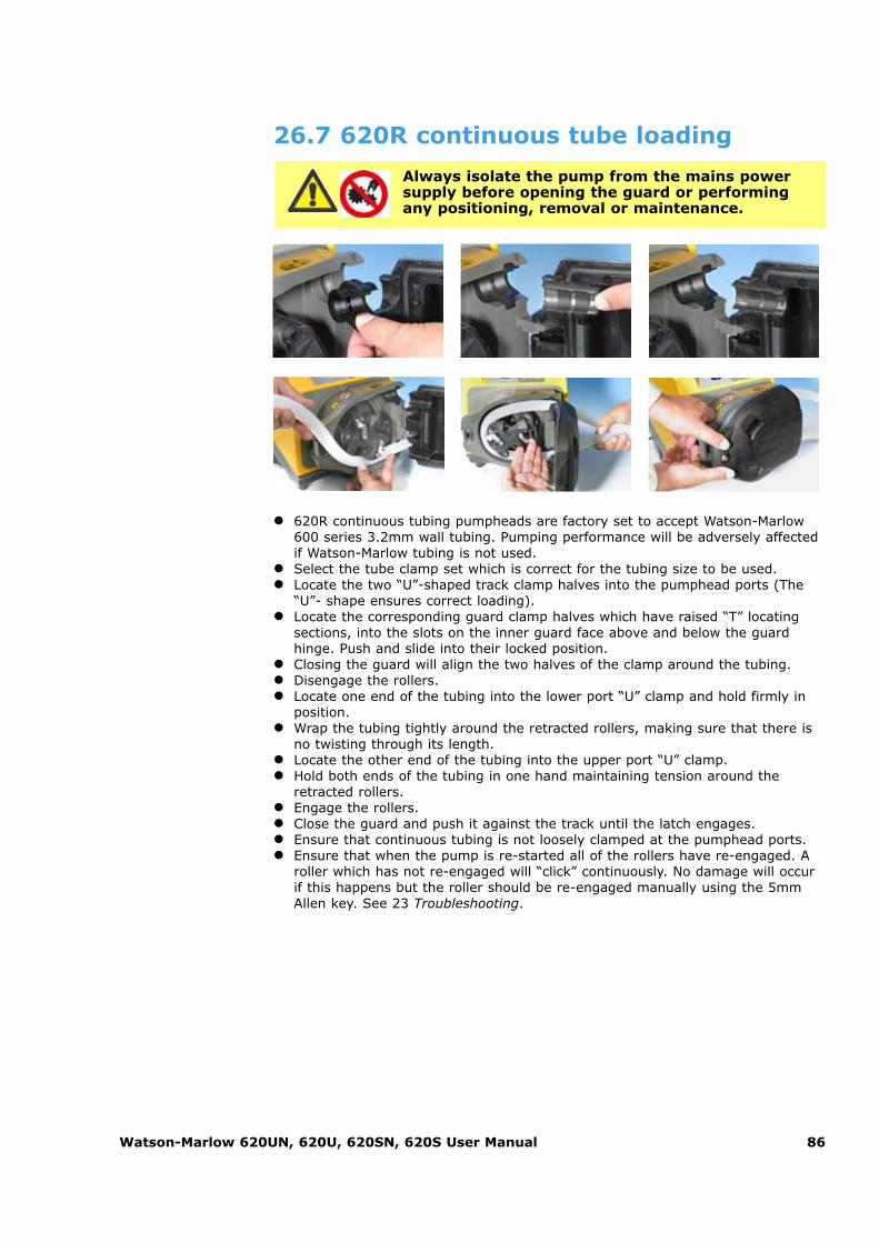
Watson-Marlow 620UN, 620U, 620SN, 620S User Manual 86
� 620R continuous tubing pumpheads are factory set to accept Watson-Marlow600 series 3.2mm wall tubing. Pumping performance will be adversely affectedif Watson-Marlow tubing is not used.
� Select the tube clamp set which is correct for the tubing size to be used. � Locate the two “U”-shaped track clamp halves into the pumphead ports (The
“U”- shape ensures correct loading).� Locate the corresponding guard clamp halves which have raised “T” locating
sections, into the slots on the inner guard face above and below the guardhinge. Push and slide into their locked position.
� Closing the guard will align the two halves of the clamp around the tubing.� Disengage the rollers.� Locate one end of the tubing into the lower port “U” clamp and hold firmly in
position. � Wrap the tubing tightly around the retracted rollers, making sure that there is
no twisting through its length. � Locate the other end of the tubing into the upper port “U” clamp. � Hold both ends of the tubing in one hand maintaining tension around the
retracted rollers. � Engage the rollers.� Close the guard and push it against the track until the latch engages.� Ensure that continuous tubing is not loosely clamped at the pumphead ports. � Ensure that when the pump is re-started all of the rollers have re-engaged. A
roller which has not re-engaged will “click” continuously. No damage will occurif this happens but the roller should be re-engaged manually using the 5mmAllen key. See 23 Troubleshooting.
Always isolate the pump from the mains powersupply before opening the guard or performingany positioning, removal or maintenance.
26.7 620R continuous tube loading

Watson-Marlow 620UN, 620U, 620SN, 620S User Manual 87
26.8 620RE, 620RE4 and 620R tube element or continuous tube removal
Always isolate the pump from the mains powersupply before opening the guard or performingany positioning, removal or maintenance.
� Unlock the guard and disengage the rollers. � Disconnect the tubing from the external pipeline. � Remove the tubing from the pumphead.
26.9 620RE, 620RE4 and 620R maintenance Scheduled maintenance
� The stainless steel pumping rollers run on sealed bearings and do not requirelubrication.
� Remove the rotor and lubricate the follower rollers and roller engaging mecha-nisms with a lithium-based grease. This should be carried out every six monthsfor intermittent duties and every three months for 24 hour duties.
� If fluid is spilled inside the pumphead, flush the pumphead out with water andmild detergent as soon as possible. If specific cleaning agents are required toclean the spillage, please consult Watson-Marlow Technical Support Officebefore proceeding, in order to confirm chemical compatibility.
� If the rotor needs to be removed, refer to the guidelines below.
Roller adjustment
620 pumpheads have provision for adjustment to reset the roller/track gap to com-pensate for wear after extended service in arduous applications.
Roller/track gaps can only be accurately judged without tubing in the pumphead.The gap should be 4.6mm for 3.2mm wall tubing and 5.5mm for LoadSure ele-ments.
If the gap is more than 0.2mm greater than these dimensions, the following may becarried out: � Note the number on the roller arm to which the engraved line on the hexagon-
headed main roller pin corresponds. � Remove the circlip (snap-ring) and roller pin. � Relocate the main roller pin, resetting the engraved line to one number lower.
For example, if the engraved line was at "-1", reset it to "-2" to reduce theroller track gap.
� Ensure the roller pin is correctly seated into the roller arm thrust washer.Replace the circlip.

Watson-Marlow 620UN, 620U, 620SN, 620S User Manual 88
Rotor removal
� Remove the rotor cover by hand and the central locating bolt using a 5mmAllen key. Pull the rotor off the keyed shaft. Do not use tools to lever the rearface of the rotor away from the inner face of the track: it should come off byhand.
Track removal
� Remove the rotor as described above. � Disconnect the waste pipework (if attached).
� Loosen the two track retaining screws using a suitable screwdriver. � Withdraw the track fully from the gearbox. � After removing the rotor and track, it is advisable to remove the metal key
from the keyway, clean and reassamble. The key fits its keyway tightly. It maybe freed by tapping gently with a screwdriver or other suitable tool.

Watson-Marlow 620UN, 620U, 620SN, 620S User Manual 89
Track re-location
� Ensure that the track is clean. � Align the track so that the location holes are
aligned with the threaded holes in the cased drive. � Tighten the two track retaining screws using a
suitable screwdriver. � Re-connect the waste pipework (if required).
Note: The track can be fitted in two positions: with ports to the right or with portsdown. The ports-down position requires that the pump is positioned at the front ofthe surface it stands on to provide clearance for the supply and discharge tubes.
Rotor re-location
� Before replacing the rotor, locate the key into the driveshaft keyway and applya thin layer of grease over the shaft and key. The rotor keyway is the largest ofthe four slots radiating from the driveshaft socket: the top one in the first pic-ture, above. Align the rotor keyway with the shaft key and slide the rotor intoposition, ensuring that a positive “stop” is achieved and ensure that the fulllength of the drive shaft is fitted into the rotor.
� Do not force the rotor into position. The rotor will slide into place easily if cor-rectly aligned.
� Secure the rotor with the hexagonal locating bolt (complete with washer) to anominal torque of 10Nm using a 5mm Allen key.
� The rotor bolt, which is impregnated with “Loctite 218” thread lock, should besubjected to a maximum of three removals/relocations before renewal. To avoidrotor bolt renewal after three removals, apply “Loctite 222” thread lock to therotor thread before relocation. This is critical to ensure prolonged, secure loca-tion of the rotor hub to the drive shaft. Failure to complete this action willinvalidate the terms and conditions of the warranty.
� Replace the rotor cover.
When closing the guard, check it does not make contact with the rotor. If it does,the rotor has been fitted incorrectly. Re-open the guard, remove and refit the rotor,and close the guard.
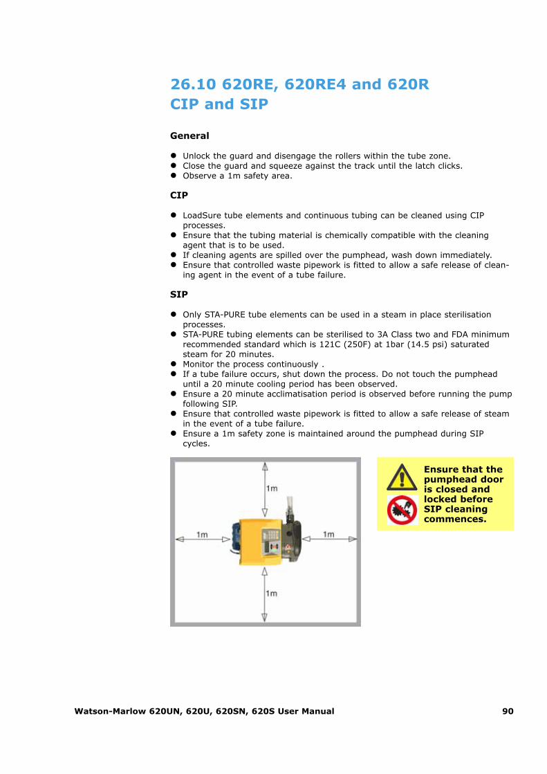
Watson-Marlow 620UN, 620U, 620SN, 620S User Manual 90
26.10 620RE, 620RE4 and 620R CIP and SIP
General
� Unlock the guard and disengage the rollers within the tube zone. � Close the guard and squeeze against the track until the latch clicks. � Observe a 1m safety area.
CIP
� LoadSure tube elements and continuous tubing can be cleaned using CIPprocesses.
� Ensure that the tubing material is chemically compatible with the cleaningagent that is to be used.
� If cleaning agents are spilled over the pumphead, wash down immediately. � Ensure that controlled waste pipework is fitted to allow a safe release of clean-
ing agent in the event of a tube failure.
SIP
� Only STA-PURE tube elements can be used in a steam in place sterilisationprocesses.
� STA-PURE tubing elements can be sterilised to 3A Class two and FDA minimumrecommended standard which is 121C (250F) at 1bar (14.5 psi) saturatedsteam for 20 minutes.
� Monitor the process continuously . � If a tube failure occurs, shut down the process. Do not touch the pumphead
until a 20 minute cooling period has been observed. � Ensure a 20 minute acclimatisation period is observed before running the pump
following SIP. � Ensure that controlled waste pipework is fitted to allow a safe release of steam
in the event of a tube failure. � Ensure a 1m safety zone is maintained around the pumphead during SIP
cycles.
Ensure that thepumphead dooris closed andlocked beforeSIP cleaningcommences.

Watson-Marlow 620UN, 620U, 620SN, 620S User Manual 91
26.11 620RE, 620RE4 and 620R pumphead spares
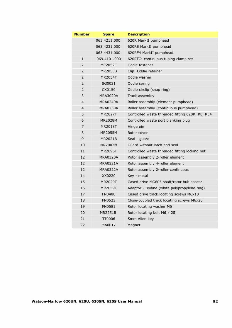
Watson-Marlow 620UN, 620U, 620SN, 620S User Manual 92
Number Spare Description
063.4211.000 620R MarkII pumphead
063.4231.000 620RE MarkII pumphead
063.4431.000 620RE4 MarkII pumphead
1 069.4101.000 620RTC: continuous tubing clamp set
2 MR2052C Oddie fastener
2 MR2053B Clip: Oddie retainer
2 MR2054T Oddie washer
2 SG0021 Oddie spring
2 CX0150 Oddie circlip (snap ring)
3 MRA3020A Track assembly
4 MRA0249A Roller assembly (element pumphead)
4 MRA0250A Roller assembly (continuous pumphead)
5 MR2027T Controlled waste threaded fitting 620R, RE, RE4
6 MR2028M Controlled waste port blanking plug
7 MR2018T Hinge pin
8 MR2055M Rotor cover
9 MR2021B Seal - guard
10 MR2002M Guard without latch and seal
11 MR2096T Controlled waste threaded fitting locking nut
12 MRA0320A Rotor assembly 2-roller element
12 MRA0321A Rotor assembly 4-roller element
12 MRA0322A Rotor assembly 2-roller continuous
14 XX0220 Key - metal
15 MR2029T Cased drive MG605 shaft/rotor hub spacer
16 MR2059T Adaptor - Bodine (white polypropylene ring)
17 FN0488 Cased drive track locating screws M6x10
18 FN0523 Close-coupled track locating screws M6x20
19 FN0581 Rotor locating washer M6
20 MR2251B Rotor locating bolt M6 x 25
21 TT0006 5mm Allen key
22 MA0017 Magnet

Watson-Marlow 620UN, 620U, 620SN, 620S User Manual 93
27 620RE, 620RE4 and 620R performance dataPumping conditions
All performance figures in this operating instruction have been recorded againstpeak pipeline pressures.
This pump is rated to 4 bar (58psi) peak pressure when fitted with a 620RE or620RE4 pumphead using high-pressure tubing. However, it will generate in excessof 4 bar (58psi) peak pressure if the pipeline is restricted. Where it is important that4 bar (58psi) is not exceeded, pressure relief valves should be installed in thepipeline.
Viscosity handling is maximised by using 4.0mm wall LoadSure elements with the620RE and 620RE4 pumpheads.
Flow rates are normalised test values obtained using new tubing with the pumpheadrotating clockwise pumping water at 20C with negligible inlet and discharge pressures. Actual flow rates achieved may vary because of changes in temperature,viscosity, inlet and discharge pressures, system configuration and tubing perform-ance against time. Flow rates may also vary due to normal manufacturing tolerancesof the tubing. These tolerances will make flow rate variance more pronounced atsmaller bore sizes.
For precise and repeatable performance it is important to determine flowrates under operating conditions for each new piece of tubing.
620R family pumpheads' flow rates are directly proportional to rotor speed. If youwish to run the pump at a speed not shown in the tables below, flow figures can bereached by dividing the maximum flow shown in the tables below by the maximumrpm figure, and multiplying the result by your required speed in rpm.
In normal circumstances, rotor and tube life are maximised if the pumphead is runslowly, particularly when pumping at high pressure. However, to maintain performance at pressures above 2 bar, avoid running the pumphead below 50 rpm.If low-flow, high-pressure operation is necessary, switching to a smaller tube is recommended.
Sta-Pure and Marprene TM tubing are hard to compress when new. When using tubing made of these materials, the first five pumphead revolutions should be at aspeed of 10rpm or greater. If the pump is run slower, the safety system built intopump drive’s software may cause it to stop and display an over-current error message.
Note: Flow rates quoted have been rounded for simplicity, but are accurate to with-in 5% - well within the normal tubing tolerance variation of flow rate. They shouldtherefore be taken as a guide. Real flow rates in any application must be determinedempirically.

Watson-Marlow 620UN, 620U, 620SN, 620S User Manual 94
27.1 620RE, 620RE4 and 620R flow ratesMetric (SI)
620 Pumpsil silicone, l/min
620R 620RE 620RE4
Speedrpm
6.4mm
9.6mm
12.7mm
15.9mm
12.0mm
17.0mm
12.0mm
17.0mm
0.1 0.001 0.003 0.004 0.01 0.004 0.01 0.003 0.004
265 3.2 7.2 11 15 10 16 8.7 11
620 Marprene TM, Bioprene TM, l/min
620RE(hard)
620RE4(hard)
Speedrpm
12.0mm
17.0mm
12.0mm
17.0mm
0.1 0.004 0.01 0.003 0.004
265 9.8 16 8.3 11
620 Marprene TL, Bioprene TL, l/min
620R (standard) 620RE (standard)
620RE4 (standard)
Speedrpm
6.4mm
9.6mm
12.7mm
15.9mm
12.0mm
17.0mm
12.0mm
17.0mm
0.1 0.001 0.003 0.004 0.01 0.004 0.01 0.003 0.005
265 3.4 6.6 11 12 9.8 18 8.3 12
620 Sta-Pure, Chem-Sure, Neoprene, l/min
620R 620RE 620RE4
Speedrpm
6.4mm
9.6mm
12.7mm
15.9mm
12.0mm
17.0mm
12.0mm
17.0mm
0.1 0.001 0.003 0.004 0.01 0.004 0.01 0.003 0.01
265 3.2 6.6 11 16 11 18 9.0 13

Watson-Marlow 620UN, 620U, 620SN, 620S User Manual 95
US (imperial)
620 Sta-Pure, Chem-Sure, Neoprene, USGPM
620R 620RE 620RE4
Speedrpm
6.4mm
9.6mm
12.7mm
15.9mm
12.0mm
17.0mm
12.0mm
17.0mm
0.1 0.0003 0.001 0.001 0.002 0.001 0.002 0.001 0.001
265 0.8 1.8 2.8 4.3 2.8 5.1 2.4 3.5
620 Marprene TL, Bioprene TL, USGPM
620R (standard) 620RE(standard)
620RE4(standard)
Speedrpm
6.4mm
9.6mm
12.7mm
15.9mm
12.0mm
17.0mm
12.0mm
17.0mm
0.1 0.0003 0.001 0.001 0.002 0.001 0.002 0.001 0.001
265 0.9 1.8 2.8 3.0 2.6 4.7 2.2 3.3
620 Marprene TM, Bioprene TM, USGPM
620RE(hard)
620RE4(hard)
Speedrpm
12.0mm
17.0mm
12.0mm
17.0mm
0.1 0.001 0.002 0.001 0.001
265 2.6 4.1 2.2 2.9
620 Pumpsil silicone, USGPM
620R 620RE 620RE4
Speedrpm
6.4mm
9.6mm
12.7mm
15.9mm
12.0mm
17.0mm
12.0mm
17.0mm
0.1 0.0003 0.001 0.001 0.001 0.001 0.002 0.001 0.001
265 0.8 1.9 2.9 3.9 2.7 4.3 2.3 3.0

Watson-Marlow 620UN, 620U, 620SN, 620S User Manual 96
28 Continuous tubing product codes(620R)
mm inch # Marprene Bioprene Pumpsil silicone
6.4 1/4 26 902.0064.032 903.0064.032 913.0064.032
9.6 3/8 73 902.0096.032 903.0096.032 913.0096.032
12.7 1/2 82 902.0127.032 903.0127.032 913.0127.032
15.9 5/8 184 902.0159.032 903.0159.032 913.0159.032
mm inch # Sta-Pure Neoprene PVC
6.4 1/4 26 960.0064.032 920.0064.032 950.0064.032
9.6 3/8 73 960.0096.032 920.0096.032 950.0096.032
12.7 1/2 82 960.0127.032 920.0127.032 950.0127.032
15.9 5/8 184 960.0159.032 920.0159.032 950.0159.032
mm inch # Fluorel Chem-Sure
6.4 1/4 26 970.0064.032 965.0064.032
9.6 3/8 73 970.0096.032 965.0096.032
12.7 1/2 82 970.0127.032 965.0127.032
15.9 5/8 184 970.0159.032 965.0159.032

Watson-Marlow 620UN, 620U, 620SN, 620S User Manual 97
29 LoadSure tube element productcodes (620RE and 620RE4)
12mm Tri-clamp
3/4in
17mm Tri-clamp
3/4in
12mm Camand Groove
3/4in
17mm Camand Groove
3/4in
Sta-Pure 960.0120.PFT 960.0170.PFT
Chem-Sure 965.0120.SST 965.0170.SST
Bioprene TM 903.P120.PFT 903.P170.PFT
Bioprene TL 903.0120.PFT 903.0170.PFT
Pumpsil silicone
913.0120.PFT 913.0170.PFT
Marprene TM 902.P120.PPC 902.P170.PPC
Marprene TL 902.0120.PPC 902.0170.PPC
Neoprene 920.0120.PPC 920.0170.PPC
Note: = for 4 bar use

Watson-Marlow 620UN, 620U, 620SN, 620S User Manual 98
Accessory Description Part code Pump compatibility
520AF Footswitch with 25-pin D-connector 059.3002.000 620U, 620Du, 620Di
624AF Footswitch, bare lead 069.5231.000 620UN, 620DuN, 620DiN
520AH Handswitch with 25-pin D-connector 059.3022.000 620U, 620Du, 620Di
520ANC Network cable, RS232, with 9-pin D-connectors 059.3121.000 620Du, 620Di
520ANX Network extension cable with 9-pin D-connectors 059.3122.000 620Du, 620Di
520ANA Network adaptor, 25-pin to 9-pin D-connector 059.3123.000
520AB Batch records cable with 9-pin D-connectors 059.3125.000 620Di
624AV Proximity switch for 624AS filling stand 069.5271.000 620UN, 620DuN, 620DiN
624AS Stainless steel filling stand for 624AFN filling needles 069.5001.000 All models
624AFN Filling needle set (3 sizes) 069.5101.000 All models
Filling needle for 8.0mm bore tubing 069.5100.080 All models
Filling needle for 12.0mm bore tubing 069.5100.120 All models
Filling needle for 16.0mm bore tubing 069.5100.160 All models
624AL Dispensing lance for use with 624AFN filling needles 069.5251.000 All models
Tube monitor with 25-pin D-connector 059.4501.520 620U, 620Du, 620Di
Tube monitor, bare lead 059.450N.520 620UN, 620DuN, 620DiN
620AL Leak detector kit, bare lead 069.7131.000 620UN, 620DuN, 620DiN
30 620 series pumping accessoriesUN, U, SN, S

Watson-Marlow 620UN, 620U, 620SN, 620S User Manual 99
31 TrademarksWatson-Marlow, Bioprene, Pumpsil and Marprene are trademarks of Watson-MarlowLimited.
Fluorel is a trademark of 3M.
Sta-Pure and Chem-Sure are trademarks of W.L.Gore and Associates.
32 Warning not to use pumps inpatient-connected applicationsWarning: These products are not designed for use in, and should not be used forpatient-connected applications.
33 Publication historym-620un-u-sn-s-gb-01.qxp: Watson-Marlow 620UN, 620U, 620SN, 620S.
First published 10 05. Revised 01 08.
UN, U, SN, S
UN, U, SN, S
UN, U, SN, S

Watson-Marlow 620UN, 620U, 620SN, 620S User Manual 100
34 Decontamination certificateIn compliance with the UK Health and Safety at Work Act and the Control ofSubstances Hazardous to Health Regulations, you are required to declare the sub-stances which have been in contact with product(s) you return to Watson-Marlow orits subsidiaries or distributors. Failure to do so will cause delays. Please ensure thatyou fax us this form and receive an RGA (Returned Goods Authorisation) before youdespatch the product(s). A copy of this form must be attached to the outside of thepackaging containing the product(s). Please complete a separate decontaminationcertificate for each product. You are responsible for cleaning and decontaminatingthe product(s) before return.
UN, U, SN, S
Your name Company
Address
Postcode/zip Country
Telephone Fax
Product type Serial number
To speed therepair, please
describe all known faults
The product has ... �� Been used �� Not been used
If the product has been used, please complete all the following sections. If the product has not been used, please just sign this form.
Names of chemicals handled
with product(s)
Precautions to betaken in handling
these chemicals
Action to be takenin the event ofhuman contact
I understand that the personal data collected will be kept confidentially in accordance with the UK Data Protection Act 1998.
RGA number
Signature Your position
Date
Please print out, sign and fax to Watson-Marlow Pumps at +44 1326 376009.