Embed Size (px)
Citation preview
620S Boiler-Trak™ Instruction Manual Table of Contents
IM-62 BT-A 0-1
Sierra Series 620S Boiler-Trak™
Insertion Mass Flow Meter
Instruction Manual Part Number IM-62 BT
Revision A.2, February 2012
Table of Contents 620S Boiler-Trak™ Instruction Manual
0-2 IM-62 BT-A
GLOBAL SUPPORT LOCATIONS: WE ARE HERE TO HELP!
CORPORATE HEADQUARTERS 5 Harris Court, Building L Monterey, CA 93940 Phone (831) 373-0200 (800) 866-0200 Fax (831) 373-4402 www.sierrainstruments.com
EUROPE HEADQUARTERS Bijlmansweid 2 1934RE Egmond aan den Hoef The Netherlands Phone +31 72 5071400 Fax +31 72 5071401
ASIA HEADQUARTERS Rm. 618, Tomson Centre, Bldg A, 188 Zhang Yang Road Pu Dong New District, Shanghai, P.R. China Phone: + 8621 5879 8521 Fax: +8621 5879 8586
© COPYRIGHT SIERRA INSTRUMENTS 2011 No part of this publication may be copied or distributed, transmitted, transcribed, stored in a re-trieval system, or translated into any human or computer language, in any form or by any means, electronic, mechanical, manual, or otherwise, or disclosed to third parties without the express writ-ten permission of Sierra Instruments. The information contained in this manual is subject to change without notice. TRADEMARKS Boiler-Trak™ and Smart Interface™ Series is a Registered Trademark of Sierra Instruments, Inc. Other product and company names listed in this manual are trademarks or trade names of their re-spective manufacturers.
620S Boiler-Trak™ Instruction Manual Table of Contents
IM-62 BT-A 0-3
Table of Contents
Chapter 1 Introduction 620S Boiler-Trak™ Mass Flow Meters ................................................. 1-1 Using this Manual .......................................................................... 1-1 Note and Safety Information .......................................................... 1-2 Receipt of System Components ..................................................... 1-2 Technical Assistance ..................................................................... 1-2 The 620S Boiler-Trak Flow Sensing Principle ...................................... 1-3 Boiler-Trak™ Electronics Features ....................................................... 1-4 Enclosure Options ................................................................................ 1-5 Smart Interface Software ...................................................................... 1-5
Chapter 2 Installation and Wiring Installation Overview ............................................................................ 2-1 Site Selection ................................................................................. 2-1 Unobstructed Flow Requirements .................................................. 2-2 Installation ............................................................................................ 2-3 Wiring Connections .............................................................................. 2-4 Input Power Wiring ......................................................................... 2-4 Output Signal Wiring ...................................................................... 2-5 Alarm Output Wiring ....................................................................... 2-7 Remote Sensor Probe Wiring ........................................................ 2-8 Range Selection Wiring .................................................................. 2-9
Chapter 3 Operating Instructions Using the Boiler-Trak™ Electronics Basic Features ............................. 3-1 Using the Single-Digit LED for Programming ................................. 3-2 Using the LCD Display for Programming ....................................... 3-3 Entering Alarm Parameters ............................................................ 3-4 K-factor Adjustment ....................................................................... 3-5 User Full Scale Adjustment ............................................................ 3-6 Time Response Delay Adjustment ................................................. 3-7 Totalizer Reset ............................................................................... 3-7 Using the Boiler-Trak™ Electronics Advanced Features ...................... 3-8 Voltage Zero Adjustment................................................................ 3-8 Voltage Span Adjustment ............................................................... 3-8 Current Zero Adjustment ................................................................ 3-9 Current Span Adjustment ............................................................... 3-9 Instrument Validation .......................................................................... 3-10 Electronics Validation Procedure ................................................. 3-11 Sensor Validation Procedure ....................................................... 3-12
Table of Contents 620S Boiler-Trak™ Instruction Manual
0-4 IM-62 BT-A
Chapter 4 Troubleshooting and Repair Troubleshooting the Flow Meter ........................................................... 4-1 Obtaining a Return Material Authorization ............................................ 4-3
Appendix A Product Specifications
Appendix B 620S Boiler-Trak™ Packing Gland
Appendix C 620S Boiler-Trak™ Modbus
List of Figures 1-1. 620S Boiler-Trak™ Sensor Assembly ..................................... 1-3 2-1. Recommended Pipe Length Requirements ............................. 2-2 2-2. Wiring Access .......................................................................... 2-4 2-3. Input Power Connections ........................................................ 2-4 2-4. Output Signal Wiring ................................................................ 2-5 2-5. Isolated 4-20 mA Current Loop Connections ........................... 2-6 2-6. Non-isolated 4-20 mA Current Loop Connections ................... 2-6 2-7. Isolated Alarm Output Connections ......................................... 2-7 2-8. Non-isolated Alarm Output Connections ................................. 2-7 2-9. Remote Electronics to Sensor Connections ............................ 2-8 2-10. Sensor J Box to Remote Enclosure Connections .................... 2-8 2-11. Range Selection Wiring ........................................................... 2-9 3-1. Display/Keypad Commands .................................................... 3-1 3-2. Electronics Validation Component Locations ......................... 3-10 3-3. Sensor Validation Component Locations ............................... 3-12
List of Tables 3-1. Electronics Validation Results ............................................... 3-12 3-2. Sensor Validation Results ..................................................... 3-13
620S Boiler-Trak™ Instruction Manual Table of Contents
IM-62 BT-A 0-5
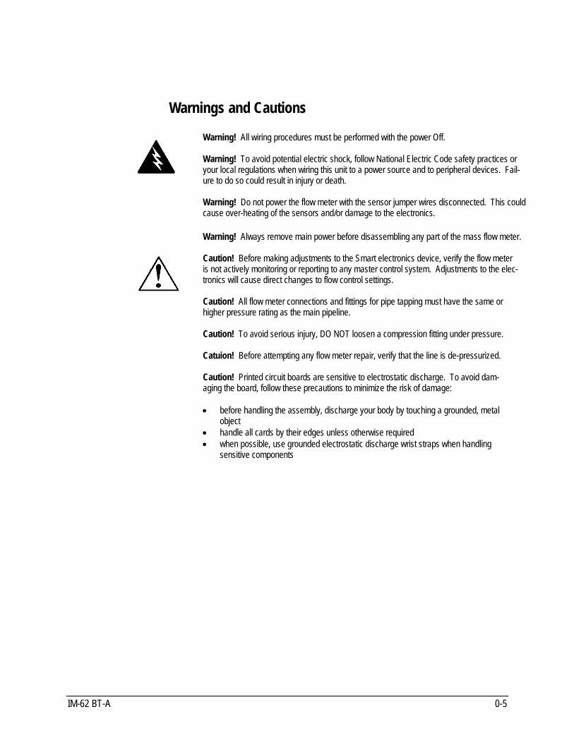
Warnings and Cautions Warning! All wiring procedures must be performed with the power Off. Warning! To avoid potential electric shock, follow National Electric Code safety practices or your local regulations when wiring this unit to a power source and to peripheral devices. Fail-ure to do so could result in injury or death. Warning! Do not power the flow meter with the sensor jumper wires disconnected. This could cause over-heating of the sensors and/or damage to the electronics. Warning! Always remove main power before disassembling any part of the mass flow meter. Caution! Before making adjustments to the Smart electronics device, verify the flow meter is not actively monitoring or reporting to any master control system. Adjustments to the elec-tronics will cause direct changes to flow control settings. Caution! All flow meter connections and fittings for pipe tapping must have the same or higher pressure rating as the main pipeline. Caution! To avoid serious injury, DO NOT loosen a compression fitting under pressure. Catuion! Before attempting any flow meter repair, verify that the line is de-pressurized. Caution! Printed circuit boards are sensitive to electrostatic discharge. To avoid dam-aging the board, follow these precautions to minimize the risk of damage: • before handling the assembly, discharge your body by touching a grounded, metal
object • handle all cards by their edges unless otherwise required • when possible, use grounded electrostatic discharge wrist straps when handling
sensitive components

620S Boiler-Trak™ Instruction Manual Chapter 1 Introduction
IM-62 BT-A 1-1
Chapter 1 Introduction
620S Boiler-Trak™ Mass Flow Meters Sierra’s 620S Boiler-Trak™ provides a reliable solution for natural gas, methane, or propane gas flow measurement applications. Low-flow sensitivity, fast response and outstanding rangeability have made this model the instrument of choice for many critical gas flow applications. The Boiler-Trak™ microprocessor-based transmitter integrates the functions of flow-range adjustment, meter validation and diagnostics in a probe-mounted or remote NEMA 4X (IP65) housing. Mass flow rate and totalized flow, as well as other configuration variables can be dis-played on the meter’s optional 2 x 12 backlit LCD panel. The meter provides an optical/galvanic isolated flow output, two alarm outputs and one contact input for range or gas selection. The programmable trans-mitter is easily configured via RS-232 and Sierra’s Smart Interface soft-ware or through three push buttons built into the device. Depending on the probe length, the 620S Boiler-Trak™ is suitable for pipes or ducts from 1 inch up to 24 inches (DN25 up to DN600) . The 620S Boiler-Trak’s simple installation combines with an easy-to-use in-terface that provides quick set up, long term reliability and accurate mass flow measurement over a wide range of conditions. Modbus communication is standard.
Using This Manual This manual provides the information you need to install and operate the 620S Boiler-Trak™. The four chapters of this manual cover these areas: • Chapter 1 includes the introduction and product description • Chapter 2 provides installation and wiring instructions • Chapter 3 describes system operation and programming • Chapter 4 covers troubleshooting and repair The product specifications and dimensional drawings are found in Ap-pendix A. Dimensional drawings of the Packing Gland for the Hot Tap are in Appendix B. Modbus details are in Appendix C.

Chapter 1 Introduction Series 620S Instruction Manual
1-2 IM-62 BT-A
Note and Safety Information We use note, caution and warning statements throughout this book to draw your attention to important information.
Warning! Caution! Note This statement ap-pears with information that is important to protect people and equipment from dam-age. Pay very close attention to all warn-ings that apply to your application.
This statement ap-pears with infor-mation that is im-portant for protecting your equipment and performance. Read and follow all cau-tions that apply to your application.
This statement ap-pears with a short message to alert you to an important detail.
Receipt of System Components When receiving a Sierra mass flow meter, carefully check the outside packing carton for damage incurred in shipment. If the carton is dam-aged, notify the local carrier and submit a report to the factory or distribu-tor. Remove the packing slip and check that all ordered components are present. Make sure any spare parts or accessories are not discarded with the packing material. Do not return any equipment to the factory without a Return Material Authorization (RMA, see Chapter 4).
Technical Assistance If you encounter a problem with your flow meter, review the configuration information for each step of the installation, operation and setup proce-dures. Verify that your settings and adjustments are consistent with facto-ry recommendations. Refer to Chapter 4, Troubleshooting, for specific in-formation and recommendations. If the problem persists after following the troubleshooting procedures outlined in Chapter 4, contact Sierra Instruments by fax or by E-mail ([email protected]). For phone support you may call (800) 866-0200 or (831) 373-0200 between 8:00 a.m. and 5:00 p.m. PST. In Europe contact Sierra Instruments b.v. at +31 20 6145810. When contacting Technical Support, make sure to in-clude this information: • the flow range, serial number and Sierra order number and model
number (all marked on the meter nameplate) • if possible, the firmware version (visible at start up on the
meter display) • the problem you are encountering and any corrective action taken • application information (gas, pressure, temperature, piping
configuration)

620S Boiler-Trak™ Instruction Manual Chapter 1 Introduction
IM-62 BT-A 1-3
The 620S Boiler-Trak™ Flow Sensing Principle Sierra’s unique 620S Boiler-Trak™ sensor probe is responsible for the unsurpassed accuracy and reliability of Sierra mass flow meters. The sensor consists of two sensing elements–a velocity sensor and a tem-perature sensor which automatically corrects for changes in gas temper-ature. When power is applied to the flow meter, the transducer electron-ics heats the velocity sensor to a constant temperature differential above the gas temperature and measures the cooling effect of the gas flow. The electrical power required to maintain a constant temperature differ-ential is directly proportional to the gas mass flow rate. The meter elec-tronics measure this power and convert it into a linear 0-5 VDC (0-10 VDC optional) and 4-20 mA output signal. The Boiler-Trak™ sensors are reference-grade platinum resistance tem-perature detectors (RTD) encapsulated in glass. The platinum RTD wire is wound on a rugged ceramic mandrel for strength and stability. The sensor is located at the tip of a 0.375 inch (3/8”) diameter, 304 stainless steel probe which is inserted in the gas stream. The Boiler-Trak elec-tronics are packaged in a weather-proof NEMA 4X (IP65) enclosure mounted either directly on the sensing probe or remotely up to 100 feet (60 meters) away.
Figure 1-1. 620S Boiler-Trak™ Sensor Assembly

Chapter 1 Introduction Series 620S Instruction Manual
1-4 IM-62 BT-A
Boiler-Trak™ Electronics Features Instrument Validation Two simple tests offer full “field-validation” of your Boiler-Trak™ mass flow meter. The first test checks the system electronics, linearization and microprocessor functionality. This is performed by injecting a known input value and confirming that the flow meter outputs the expected value. The second test verifies that the instrument’s primary sensing elements have not drifted or shifted from their original calibration. This is accomplished by measuring the resistance of the velocity and temperature sensors and comparing the results to the NIST-traceable calibration data provided with the flow meter. Together, these tests confirm that your meter is working correctly and the calibration variables did not drift, shift or change values.
Dual Range or Dual Gas Calibration (Optional) Select one of two factory calibrated flow ranges using a simple external customer-supplied single contact closure.
User Full Scale Flow Rate Field-configure from 50% to 100% of the factory full scale setting (factory full scale is normally set to 125% of the user-specified maximum flow rate). This adjustment can be made for each flow range.
Alarms Program high and low or window alarm limits independently for each flow range. The solid state contacts are isolated with one common.
K-Factor Correction Change the calibration correction factor to compensate for flow profile dis-turbances or specific application conditions. The K-factor is a multiplica-tion factor applied to the linearized flow signal. You may set the K-factor individually for each flow range.
Dual Output Signals Boiler-Trak™ offer two separate linear output signals proportional to flow, 0-5 VDC (0-10 VDC optional) and 4-20 mA. The 4-20 mA output can be field-configured as an active loop powered by the flow meter or an optically isolated passive loop requiring an external power supply.

620S Boiler-Trak™ Instruction Manual Chapter 1 Introduction
IM-62 BT-A 1-5
Totalizer With the optional LCD display, actual mass flow appears on line 1 and the totalized flow on line 2 both in the user-specified engineering units. The totalizer counts only the selected range and when ranges are switched, the value of the non-selected range is stored in memory. You may reset the totalizer using the 3 function buttons mounted on the PCA or by using a hand-held magnet.
Zero and Span Outputs Validate and adjust the settings to ensure output circuits are correct.
Time Response Delay Select from a low response for faster tracking to a high response for a smoother output.
Enclosure Options Flow meter electronics are available mounted directly to the flow body, or remotely mounted up to 100 feet (60 meters) away. The electronics housing may be used indoors or outdoors. Display options include a 2 x 12 character LCD display of mass flow rate including totalized mass, or a single-digit LED located on the device print-ed circuit board. Local operation and reconfiguration is accomplished us-ing the three push buttons operated via finger touch. Boiler-Trak™ elec-tronics include nonvolatile memory that stores all configuration infor-mation. The memory allows the flow meter to function immediately upon power up, or after an interruption in power.
Smart Interface™ Software Sierra’s Smart Interface Windows™-based software is available for con-necting your PC directly to the Boiler-Trak™. An RS-232 serial cable along with CD-ROM containing the program and system files are avail-able from the factory. See the Smart Interface User Guide included with the software for operating instructions.

620S Boiler-Trak™ Instruction Manual Chapter 2 Installation
IM-62S-B 2-1
Chapter 2 Installation
Installation Overview The 620S Boiler-Trak™ flow meter is factory calibrated to the specific pipe size shown on the meter’s Certificate of Calibration. The factory calibration eliminates the task of calculating the average flow across the pipe to determine the correct insertion depth. Simply insert the flow me-ter sensor to the centerline position of the pipe. (If the pipe size differs from the meter’s calibrated size, return the meter to the factory for re-calibration.) When selecting an installation site, make sure that:
1. Line pressure and temperature will not exceed the flow meter rat-ing. Temperature should not vary more than 120°F (50°C) from the calibration temperature. Line pressure should not vary more than 50 psi (3.4 bar) around the calibrated pressure.
2. The location meets the required minimum number of pipe di-
ameters upstream and downstream of the sensor head (see Figure 2-1).
3. Safe and convenient access with adequate clearance. Also, verify
the meter is located where the gas is clean and dry and the meter is calibrated for the gas to be measured.
4. For remote installations, verify the supplied cable length is sufficient
to connect the flow meter sensor to the remote electronics. (Do not extend or shorten the supplied cable between the probe and the elec-tronics.)
Also, before installation check your flow system for anomalies such as: • leaks • valves or restrictions in the flow path that could create disturbances
in the flow profile that might cause unexpected flow rate indications • heaters that might cause rapid excursions in the measured temperature

Chapter 2 Installation Series 620S Instruction Manual
2-2 IM-62S-B
Unobstructed Flow Requirements Select an installation site that will minimize possible distortion in the flow profile. Valves, elbows, control valves and other piping components may cause flow disturbances. Check your specific piping condition against the examples shown below. In order to achieve accurate and repeatable performance install the flow meter using the recommended number of straight run pipe diameters upstream and downstream of the sensor.
Flow meter
A B
Example 1. One 90° elbow before meter
Flow meter
A B
Example 2. Two 90° elbows before meter in one plane
Flow meter
A B
Example 3. Two 90° elbows before meter out of plane (if three 90° bends present, double recommended length)
Flow meter
A B
Example 4. Reduction before meter
Flow meter
A B
Example 5. Expansion before meter
Example 6. Regulator or valve partially closed before meter (If valve is alwaywide open, base length requirements on fitting directly preceding
Flow meter
A B
Example
A Upstream(1) Requirements
B Downstream(2) Requirements
1 10 D 5 D 2 15 D 5 D 3 25 D 10 D 4 10 D 5 D 5 20 D 5 D 6 25 D 10 D
(1) Number of diameters (D) of straight pipe required between upstream disturbance and the flow meter. (2) Number of diameters (D) of straight pipe required downstream of the flow meter.
Figure 2-1. Recommended Pipe Length Requirements for Installation

620S Boiler-Trak™ Instruction Manual Chapter 2 Installation
IM-62S-B 2-3
Installation Use the following data as a guide to prepare the pipe for flow meter in-sertion. Refer to a standard code for all pipe tapping operations. The following instructions are general in nature and intended for guideline purposes only. 1. Turn off the flow of process gas. Verify that the line is not pressur-
ized. 2. Confirm that the installation site meets the minimum upstream and
downstream pipe diameter requirements. See Figure 2-1. 3. Use a cutting torch or sharp cutting tool to tap into the pipe. The
pipe opening must be at least .375 inches in diameter. (Do not at-tempt to insert the sensor probe through a smaller hole.)
4. Remove all burrs from the tap. Rough edges may cause flow profile
distortions that could affect flow meter accuracy. Also, obstructions could damage the sensor assembly when inserting into the pipe.
5. Mount the 3/8 inch compression fitting on the pipe. Make sure this
connection is within ± 5° perpendicular to the pipe centerline. 6. When installed, cap the fitting. Run a static pressure check on the
connection. If pressure loss or leaks are detected, repair the connec-tion and re-test.
7. Insert the sensor probe through the
compression fitting into the pipe. The correct insertion depth places the centerline of the sensor access hole in the probe at the pipe center-line.
8. Align the sensor head using the flow direction indicator. Adjust the
indicator parallel to the pipe and pointing downstream in the direction of flow.
9. Tighten the compression fitting to lock the flow meter in position.
When the compression fitting is tightened, the position is permanent (unless using Teflon ferrules).
10. Units may be hot-tapped. A suitable packing gland is required (See
Appendix B).
Caution!
All flow meter connec-tions and fittings must
have the same or higher pressure rating as the main pipeline.
Flow direction indicator points downstream
Flow Pipe centerline
Caution!
To avoid serious in-jury, DO NOT loos-en the compression
fitting under pressure.

Chapter 2 Installation Series 620S Instruction Manual
2-4 IM-62S-B
Wiring Connections The NEMA 4X enclosure contains an integral wiring compartment with one dual strip terminal block for power and signal connections and one dual strip terminal block for sensor connections. The enclosure has one 1/2 inch female NPT con-duit entry. The terminal designations are labeled inside the enclosure cover.
Smart electronics and wiring connections inside cover
To access components: 1. Loosen 4 screws. 2. Remove cover.
1/2 inch FNPT
conduit entry
Figure 2-2. Wiring Access
Input Power Wiring Depending on the flow meter configuration, connect 15 to 18 VDC (625 mA load, maximum) as shown below. Confirm power configuration be-fore applying power. See the flow meter nameplate for input power rat-ing.
TB2PWR (+)
PWR (–)
+ –
Power & signal
12
1516
Sensor1
2
56
TB1
Figure 2-3. Input Power Connections
Warning! All wiring procedures
must be performed with the power Off.
Warning! To avoid potential electric
shock, follow National Electric Code safety prac-
tices or your local code when wiring this unit to a power source and to pe-
ripheral devices. Failure to do so could result in injury
or death.
Note!
The Boiler-Trak™ input power is a Sierra exclusive
at 15 to 18 VDC.

620S Boiler-Trak™ Instruction Manual Chapter 2 Installation
IM-62S-B 2-5
Output Signal Wiring All flow meters are equipped with either a calibrated 0-5 VDC (0-10 VDC optional) or a calibrated 4-20 mA output signal. These linear output sig-nals represent 0-100% of the flow meter user full scale.
DC Output Wiring The 0-5 VDC (0-10 VDC optional) signal can drive a load of 1000 Ohms. The optional 0-10 VDC output signal is not available for power sources below 15 VDC. Connect as shown below.
V out (+)
V out (–)
12
1516
Figure 2-4. VDC Output Wiring Connections
4-20 mA Output Wiring The 4-20 mA current loop output can be self-powered by the flow meter’s power supply (non-isolated) or externally powered (isolated) requiring a separate 15 to 18 VDC power supply. Rload is the total resistance in the loop, including the wiring resistance. To calculate Rmax, the maximum Rload for the loop, use the maximum loop current, 20 mA. The voltage drop in the loop due to resistance is 20 mA times Rload and this drop is subtracted from the input voltage. Thus:
Rmax the maximum load resistance = 50 * (Vsupply – 7.5V) To use an external power supply for an isolated 4-20 mA output, connect as shown in Figure 2-5. For an internally powered non-isolated 4-20 mA output, connect as shown in Figure 2-6.

Chapter 2 Installation Series 620S Instruction Manual
2-6 IM-62S-B
Figure 2-5. Isolated 4-20 mA Current Loop Connections
4-20 out (+)
V out (–)
AUX PWR OUTJumper
CurrentR load
12
1516
(Common)
Figure 2-6. Non-isolated 4-20 mA Current Loop Connections

620S Boiler-Trak™ Instruction Manual Chapter 2 Installation
IM-62S-B 2-7
Alarm Output Wiring Two alarm outputs (Low Alarm and High Alarm) are included on the flow meter terminal block. The alarm outputs relays are normally-open single-pole relays with one common connection. There are two connection options for alarm outputs–the first with a separate power supply (isolated) and the second using the flow meter power supply (non-isolated). Use a separate power supply if a specific voltage is needed for the alarm output. Use the second (non-isolated) configuration if the volt-age at the flow meter’s power supply is an acceptable driver voltage for the load connected. (Take into account that the current used by your alarm loads have to come from the flow meter’s power supply.) In either case, the voltage of the alarm output is the same as the voltage supplied to the circuit. To use an external power supply for an isolated alarm output, connect as shown in Figure 2-7. To use the internally powered, non-isolated alarm output connect as shown in Figure 2-8. For a window alarm connect both outputs together.
ALRM RTN
Load Load
LO ALARM (–)
HI ALARM (–)
AC or DC power supply 12
1516
Figure 2-7. Isolated Alarm Output Connections
ALRM RTNLoadLoad
LO ALARM (–)HI ALARM (–)
COMMON
AUX DC PWR OUT
12
1516
Figure 2-8. Non-isolated Alarm Output Connections

Chapter 2 Installation Series 620S Instruction Manual
2-8 IM-62S-B
Remote Sensor Probe Wiring Use only factory supplied cables when connecting the sensor probe to a remotely mounted flow meter enclosure. The electronics, sensors and interconnecting cables supplied by Sierra Instruments are cali-brated as a complete precision mass flow circuit. To connect the sensor probe to a remotely mounted electronics enclo-sure, see Figure 2-9. To make wiring connections from a sensor probe junction box to a remotely mounted enclosure, see Figure 2-10.
Velocity sensor
REDGREEN
ORANGEWHITEBLACK
Temperature sensor
Remote enclosure Sensor
probe
56
12
Figure 2-9. Remote Electronics Enclosure to Sensor Connections
REDGREEN
ORANGEWHITEBLACK
Remote enclosure
Sensor probe
junction box
12
56
Figure 2-10. Sensor Junction Box to Remote Enclosure Connections
Caution! Changing the length of
cables or interchanging sensors or sensor wiring
will affect the accuracy of the flow meter. You can-
not add or subtract wire length without returning the meter to the factory
for re-calibration.

620S Boiler-Trak™ Instruction Manual Chapter 2 Installation
IM-62S-B 2-9
Range Selection Wiring If your meter is equipped with an optional second range calibration, con-nect a contact switch as shown below. When the switch is closed the de-vice changes to Range 2. Open the switch to return to Range 1.
Range 2
RNG 2
GND
Range 1
12
1516
Figure 2-11. Range Selection Wiring

620S Boiler-Trak™ Instruction Manual Chapter 3 Operation
IM-62 BT-A 3-1
Chapter 3 Operation Using the Boiler-Trak™ Electronics Basic Features
Three push buttons allow selection and adjustment of the basic user func-tions. Use the push buttons to enter:
• alarm parameters • change the user full scale • adjust the K-factor • adjust the time response speed • reset the totalizer
You may view parameters using the optional LCD front panel display or by selecting functions on the single-digit LED and viewing the meter’s 0-5 VDC output with a digital voltmeter (DVM).
Before making changes or adjustments: For meters with the optional LCD display, remove the enclosure cover to access the Boiler-Trak™ electronics. Press the FUNCTION key to view and record the factory settings. When pressing FUNCTION the optional LCD display prompts for a password, press FUNCTION again to skip the password and review the current settings. (To make changes, at the password prompt press the UP arrow until 11 is displayed, press FUNCTION to continue.) For flow meters without the display, remove the enclosure cover to access the Boiler-Trak™ electronics. Connect the DVM as described on the fol-lowing pages and record the factory-set parameters. After 12 seconds of non-activity during programming, the meter returns to the Run Mode with any new settings immediately in effect. For units without a LCD front panel display: if the unit “times-out” when entering a new parameter, press the FUNCTION button only to resume adjust-ments.
Smart electronics device located inside the flow meter enclosure. Remove the cover to enter parameters using the device buttons.
Single digit LED
FUNCTION UP DOWN
Figure 3-1. Display/Keypad Commands
Caution! Before making any ad-justment to the Boiler-
Trak™ electronics device, verify the flow meter is not
actively monitoring or re-porting to any master con-
trol system. Any adjust-ment to the electronics will
cause direct changes to flow control settings.

Chapter 3 Operation Series 620S Instruction Manual
3-2 IM-62 BT-A
Flow Meter Start Up When applying power to a flow meter equipped with the optional LCD display you will see the product name, the software version, unit serial number, the range number, the user full scale (UFS), the current flow rate and the totalized flow. Any active alarm will flash on the screen eve-ry few seconds. For meters without the optional display, when power is applied the on-board single-digit LED flashes the revision number of the software in a series of 3 digits, followed by the range number; the range number continues to flash every 3 seconds thereafter.
Using the Single-Digit LED for Programming
FUNCTION AssignmentsVersion
Voltage Span
Voltage Zero
High Alarm
Current Span
User Full Scale
K-Factor
Range in use
Software version shown in series
of 3 digits1
Run Mode
Press FUNCTION to view or change settings.
Use the UP or DOWN button to enter new parameters. Press FUNCTION to continue.
After 12 seconds of non-activity, the settings are saved and the meter returns to the Run Mode.
Current Zero
Low Alarm
Time Response Delay
Press FUNCTION
2
3
4
5
6
7
8
9
Range No.

620S Boiler-Trak™ Instruction Manual Chapter 3 Operation
IM-62 BT-A 3-3
Using the LCD Display for Programming
Version Serial No.
Sierra Flow Meter
Current flow rate Totalized flow
Span Volts
Zero Volts
High Alarm
Span mA
User FS
K-Factor
Flow Total Flow
Flow Alarm
Range No. UFS
Current range in use User full scale
Current flow rate If an alarm is active
(will flash)
Software version Meter serial number
Flow meter model
Start Up Screens
Password
Total Reset?
To view settings, press FUNCTION twice, skipping the password. To change settings, press FUNCTION, enter the password, 11, press FUNCTION to continue.
Use the UP or DOWN button to enter new parameters. Press FUNCTION to continue.
After 12 seconds of non-activity, the settings are saved and the meter returns to the Run Mode.
For units with the optional front panel LCD display, you must correctly enter the password to change parameters.
Zero mA
Low Alarm
Time Resp.
Press FUNCTION
LCD Display FUNCTIONS
Run Mode

Chapter 3 Operation Series 620S Instruction Manual
3-4 IM-62 BT-A
Entering Alarm Parameters Use the High Alarm and Low Alarm function to set or adjust alarm trip points. The alarms have a minimum hysteresis of 3% to avoid "chatter-ing." When setting a window alarm, the alarm setpoints must be at least twice the hysteresis value apart. We suggest at least a 10% separation between window alarm setpoints. If you choose not to use the high alarm for a specific alarm function, Sierra recommends that you set the high alarm at 100% of the user full scale setting which creates an “over-range” indicator. Your flow meter will continue to indicate flow and generate a signal if the flow is over the maximum range, but will not operate within the specified accuracy.
Entering Alarms with the LCD Display Enter alarms setpoints directly in engineering units. 1. Select the desired range. Press FUNCTION, enter the password.
Press FUNCTION until High Alarm or Low Alarm appears on the display.
2. Use the UP or DOWN arrow keys to enter the high or low alarm
setpoint value in engineering units. 3. Press FUNCTION to advance to the next option, or after 12 seconds
of non-activity the meter returns to the Run Mode and the new pa-rameters are in effect.
Entering Alarms without the LCD Display When using a DVM to set alarms, the setpoint is a percentage of the flow meter’s user full scale. VOLTS = (ALARM PERCENT x 5.0) If you want to alarm at 25% of user full scale, used in Step 3 below, press the UP or DOWN button until 1.25 VDC is present on the DVM. If you want to alarm at 75% of user full scale, press the UP or DOWN but-ton until 3.75 VDC is present on the DVM. 1. Set the DVM to voltage mode and connect between Vout+ and
Vout– on the flow meter terminal block. 2. Select the desired range. Press the FUNCTION button until a solid “5”
(high alarm) or solid “6” (low alarm) appears on the LED. 3. Adjust the UP or DOWN button until the DVM indicates the desired
setpoint voltage as described above. 4. Press FUNCTION again to advance to the next option, or after 12
seconds of non-activity the meter returns to the Run Mode and the new alarm parameters are in effect.
Caution! The flow meter must
not be reporting or measuring gas flow during adjustments.

620S Boiler-Trak™ Instruction Manual Chapter 3 Operation
IM-62 BT-A 3-5
K-Factor Adjustment Entering a K-factor adjusts the meter’s output signal without affecting the factory calibration curve. Use the K-factor calibration offset for additional flow profile compensation (the factory includes an initial flow profile cor-rection in the calibration curve of the unit).
Entering a K-factor with the LCD Display A K-factor value of 1.000 means the output value is not affected and is the factory default setting. You may enter any number from 0.500 to 5.000. 1. Select the desired range. Press FUNCTION, enter the password.
Press FUNCTION until K-factor appears on the display. 2. Use the UP or DOWN arrow keys to enter the desired K-factor value
in engineering units. 3. Press FUNCTION to advance to the next option, or after 12 seconds
of non-activity the meter returns to the Run Mode and the new K-factor is in effect.
Entering a K-factor without the LCD Display A K-factor value of 1.000 VDC means the output value is not affected and is the factory default setting. You may enter any value from 0.500 to 5.000 VDC in Step 3 below. If the device indicated output is 3.0 VDC and you know it should be 3.8 VDC then you could “force” the output to the desired 3.8 VDC by adjusting the K-factor to indicate 1.27 VDC (1.27 = 3.8/3.0). Use this formula to determine the desired K-factor voltage: VOLTS = DESIRED/ INDICATED 1. Set the DVM to voltage mode and connect between Vout+ and
Vout– on the flow meter terminal block. 2. Select the desired range. Press the FUNCTION button until a solid
“7” appears on the LED. 3. Adjust the UP or DOWN button until the DVM indicates the desired
K-factor value as described above. 4. Press FUNCTION to advance to the next option, or after 12 seconds
of non-activity the meter returns to the Run Mode and the new K-factor is in effect.
Caution!
The flow meter must not be reporting or
measuring gas flow during adjustments.

Chapter 3 Operation Series 620S Instruction Manual
3-6 IM-62 BT-A
User Full Scale Adjustment The user full scale (UFS) feature adjusts the flow meter output range an-ywhere within 50% to 100% of the factory full scale (FFS). This feature allows you to re-range the voltage or current output of the meter to ac-commodate different flow rates. When entering a new user full scale set-ting for Range 2, it cannot be less than 10% of the Range 1 user full scale setting.
Changing the User Full Scale with the LCD Display The factory full scale is shown on the flow meter label. If you want a UFS equal to the FFS, adjust the display to match the FFS. If you want to use 50% of FFS, adjust the display to read 50% of the FFS. 1. Select the desired range. Press FUNCTION, enter the password.
Press FUNCTION until User Full Scale appears on the display. 2. Use the UP or DOWN arrow keys to enter the desired UFS value in
engineering units. 3. Press FUNCTION to advance to the next option, or after 12 seconds
of non-activity the meter returns to the Run Mode and the new UFS is in effect.
Changing the User Full Scale without the LCD Display If the FFS is set to 11,000 sfpm and UFS is set to output 5.0 VDC, or 100%, the flow meter will indicate 5.0 VDC when 11,000 sfpm is pre-sent on the probe. If you want 6,000 sfpm for UFS, used in Step 3 be-low, adjust the UFS to 6000/11000 or 54.55% of factory full scale. Ad-just the voltage to 2.73 VDC (2.73 = 5 x .5455). Use this formula to de-termine the desired UFS voltage: VOLTS = 5 x (User Full Scale / Factory Full Scale) 1. Set the DVM to voltage mode and connect between Vout+ and
Vout– on the flow meter terminal block. 2. Select the desired range. Press the FUNCTION button until a solid
“8” appears on the LED. 3. Adjust the UP or DOWN button until the DVM indicates the desired
user full scale as described above. 4. Press FUNCTION to advance to the next option, or after 12 seconds
of non-activity the meter returns to the Run Mode and the new UFS is in effect.
Caution!
The flow meter must not be reporting or
measuring gas flow during adjustments.

620S Boiler-Trak™ Instruction Manual Chapter 3 Operation
IM-62 BT-A 3-7
Time Response Delay Adjustment Changing the Time Response Delay with the LCD Display 1. Press FUNCTION, enter the password. Press FUNCTION until Time
Response appears on the display. 2. Use the UP or DOWN button to adjust the time response delay from
0.10 to 7.2 seconds. 3. Press FUNCTION again to advance to the next option, or after 12
seconds of non-activity the meter returns to the Run Mode and the new time response setting is in effect.
Changing the Time Response Delay without the LCD Display 1. Set the DVM to voltage mode and connect between Vout+ and
Vout– on the flow meter terminal block. Select the desired range. Press the FUNCTION button until a solid “9” appears on the LED.
2. Adjust the UP or DOWN button until the DVM indicates the desired
voltage (as shown in the following table).
Volts Indicated on DVM
Time Response (Seconds)
Volts Indicated on DVM
Time Response (Seconds)
Volts Indicated on DVM
Time Response (Seconds)
Volts Indicated on DVM
Time Response (Seconds)
0.5 0.1 1.0 0.3 1.5 0.5 2.0 0.7 2.5 1.2 3.0 1.8 3.5 2.4 4.0 3.6 4.5 4.8 5.0 7.2
3. Press FUNCTION to advance to the next option, or after 12 seconds
of non-activity the meter returns to the Run Mode and the new time response delay setting is in effect.
Totalizer Reset If your device is equipped with the optional LCD display, reset the total-izer using the keypad. If you are unable to open the flow meter enclo-sure, use a magnet to reset the totalizer as shown below. 1. Select the desired range. Enter the
password. Press FUNCTION until Total Reset? appears on the display.
2. Press the UP button and then the
DOWN button until the display reads “Resetting Totalizer.”
Hold magnet here for reset

Chapter 3 Operation Series 620S Instruction Manual
3-8 IM-62 BT-A
Using the Boiler-Trak Advanced Features
Zero and span (Function 1 through 4) can be used to validate system operation and calibrate the digital to analog signals on the Boiler-Trak™. Additionally,
these functions can compensate for resistance in long signal cables connected to your data collection or in-dicating system.
You must use a certified digital voltmeter to adjust zero and span as the voltmeter acts as a standard. We recommend recording the current val-
ues as shown on the LCD display or DVM before making any changes to the zero and span settings. Note: when adjusting zero the voltage signal will be driven to 0 VDC and
when adjusting span the voltage signal will be driven to 5 VDC (or 10 VDC).
Voltage Zero Adjustment If needed, use Zero Volts (Function 1) to adjust the 0-5 VDC output to 0.0 VDC, or optional 0-10 VDC to 0.0 VDC. 1. Set the DVM to voltage mode and connect between Vout+ and Vout–. 2. Press FUNCTION, enter the password (if so equipped). Press
FUNCTION until Zero Volts appears on the LCD display or a solid “1” appears on the LED. Adjust the UP or DOWN button until the DVM in-dicates between 0 and .01 VDC (no less than 0.005). The Boiler-Trak™ electronics device cannot drive negative values.
3. After 12 seconds of non-activity, the meter returns to the Run Mode
and the new parameter is in effect.
Voltage Span Adjustment If needed, use Span Volts (Function 2) to adjust the 0-5 VDC output to 5.0 VDC, or optional 0-10 VDC to 10 VDC. 1. Set the DVM to voltage mode and connect between Vout+ and Vout–. 2. Press FUNCTION, enter the password (if so equipped). Press
FUNCTION until Span Volts appears on the LCD display or a solid “2” appears on the LED. Adjust the UP or DOWN button until the DVM, indicates between 4.99 and 5.01 VDC. (For 0-10 VDC devices, the target value is 9.99 to 10.01.)
3. After 12 seconds of non-activity, the meter returns to the Run Mode
and the new parameter is in effect.
Caution!
Adjusting zero or span will affect meter cali-
bration.

620S Boiler-Trak™ Instruction Manual Chapter 3 Operation
IM-62 BT-A 3-9
Note: when adjusting zero the current signal will be driven to 4 mA and when ad-justing span the current signal will be driven to 20 mA. We recommend recording the current values before making any changes to the current zero or span set-tings.
Current Zero Adjustment If needed, use Zero mA (Function 3) to adjust the 4-20 mA output to 4.0 mA. 1. Disconnect the 4-20 mA (+) loop wire. Set the DVM to current mode
and connect the positive lead to the wire you just disconnected. Connect the negative lead to the 4-20 mA (–) on the flow meter ter-minal block.
2. Press FUNCTION, enter the password (if so equipped). Press
FUNCTION until Zero mA appears on the LCD display or a solid “3” ap-pears on the LED. Adjust the UP or DOWN button until the DVM indi-cates between 3.95 and 4.05 mA. Set DVM back to voltage mode when adjustment is complete.
3. After 12 seconds of non-activity, the meter returns to the Run Mode
and the new parameter is in effect.
Current Span Adjustment If needed, use Span mA (Function 4) to adjust the 4-20 mA output to 20.0 mA. 1. Disconnect the 4-20 mA (+) loop wire. Set the DVM to current mode
and connect the positive lead to the wire you just disconnected. Connect the negative lead to 4-20 (–) on the flow meter terminal block.
2. Press FUNCTION, enter the password (if so equipped). Press
FUNCTION until Span mA appears on the LCD display or a solid “4” appears on the LED. Adjust the UP or DOWN button until the DVM in-dicates between 19.95 and 20.05 mA. Set DVM back to voltage mode when adjustment is complete.
3. After 12 seconds of non-activity, the meter returns to the Run Mode
and the new parameter is in effect.
Caution! Adjusting zero or span
will affect meter cali-bration.

Chapter 3 Operation Series 620S Instruction Manual
3-10 IM-62 BT-A
Instrument Validation System electronics are verified by injecting a known input value and con-firming that the flow meter outputs the expected value. This test con-firms that the microprocessor, analog to digital and digital to analog con-verters, the linearizer and the display are working properly. Sensor vali-dation is accomplished by measuring the resistance of the velocity and temperature sensors and comparing the results to the NIST-traceable calibration data provided with the flow meter. These tests confirm that your meter is working correctly and the calibration variables did not drift, shift or change values. To perform the instrument validation procedures you will need these items: • certified digital multimeter with minimum 4 character resolution, accu-
racy of at least ± 0.1% of range • Calibration Certificate supplied with the flow meter • small pot adjusting tool (screwdriver) Before beginning the validation procedures, review Figure 3-2 and Fig-ure 3-3 to familiarize yourself with the component locations.
Figure 3-2. Electronics Validation Component Locations

620S Boiler-Trak™ Instruction Manual Chapter 3 Operation
IM-62 BT-A 3-11
Electronics Validation Procedure 1. Verify the flow meter is off line from any remote communications.
Make sure the meter’s user full scale setting is the same as the fac-tory full scale setting. If not, adjust the user full scale value as need-ed.
2. Locate the Calibration Certificate supplied with the flow meter. Rec-
ord in Table 3-1 the five bridge voltage values, the output (VDC or mA) values and the indicated flow values.
3. Remove power from the flow meter. Remove the cover(s) of the flow
meter enclosure to access the wiring terminal block and the Boiler-Trak™ electronics.
4. Set the multimeter to the 20 volt range. Connect to BV(+) and BV(–)
terminals on the flow meter terminal block. 5. Move the J1 Cal/Run jumper on the Boiler-Trak™ electronics to the
CAL position. Locate potentiometer VR3 on the Boiler-Trak™ elec-tronics. Turn on power to the flow meter.
6. Adjust potentiometer VR3 until the multimeter matches the first
bridge voltage point (the value must be ± 0.002 VDC of the bridge voltage point).
7. Record the resulting flow shown on the optional LCD display in Table
3-1. If not using a display or if you prefer to validate one of the ana-log output signals, move the multimeter + connection to Vout (+). Record the resulting output voltage in Table 3-1. If using a 4-20 mA calibrated meter, set the multimeter to read current and connect the meter to read the mA signal in your connected loop. Record the re-sulting current output in Table 3-1.
8. Repeat Step 6 and Step 7 to record the results of the remaining four
bridge voltage validation points in Table 1. Compare the values rec-orded in Table 3-1. Indicated values must be within the flow meter’s stated accuracy shown on the Calibration Certificate.
9. When data collection is complete, turn off power to the flow meter.
Disconnect the multimeter from the flow meter terminal block. 10. Place the J1 Cal/Run jumper in the RUN position. Make sure the
jumper is securely in place before resuming flow meter operation. Replace the flow meter cover(s).
Caution! Before beginning this
procedure, make sure the flow meter is not
actively monitoring or reporting to any mas-
ter control system. Any adjustment to the electronics will cause
direct changes to flow control settings.

Chapter 3 Operation Series 620S Instruction Manual
3-12 IM-62 BT-A
Calibration Certificate Values Validation Test Results
Sam-ple
Point
Bridge Voltage
Indicated
Flow
Output
(V or mA)
Indicated
Flow (LCD)
Flow Meter Stated
Accura-cy
Output
(V or mA)
Flow Meter Stated
Accuracy
0%
25%
50%
75%
100%
Table 3-1. Electronics Validation Results
Sensor Validation Procedure
1. Locate the Ro temperature (measured resistance at 0°C) value and the Alpha value shown on the Calibration Certificate supplied with the
flow meter.
2. Turn off power to the flow meter. Allow a 6 minute cool-down before continuing.
3. Remove the cover of the flow meter enclosure to access the sen-
sor connection points. Remove the four-position jumper from J5, J6, J7 and J8 as shown below.
Smart Electronics Device
Remove jumper, measure on RIGHT ROW of pins
J5 temperature J6 temperature J7 velocity J8 velocity
Figure 3-3. Sensor Validation Component Location
Warning! Do not power the flow meter with the sensor jumper disconnected.
This could cause over-heating of the sensors
and/or damage to the electronics.

620S Boiler-Trak™ Instruction Manual Chapter 3 Operation
IM-62 BT-A 3-13
4. Set the multimeter to read Ohms in the 2K range. Connect the mul-
timeter to terminals J5 and J6 (temperature sensor). Measure the resistance between J5 and J6 and record the temperature sensor resistance (in Ohms) in Table 3-2.
5. Set the multimeter to read in the 200 Ohm range. Connect the multi-
meter to terminals J7 and J8 (velocity sensor). Measure the resistance between J7 and J8 and record the velocity sensor resistance (in Ohms) in Table 3-2.
6. Use the measured resistance values and the Ro and Alpha values
from the Calibration Certificate to calculate the temperature for each sensor as follows:
T = R – R
Alpha x R
T = degrees Celsius R = measured sensor resistance R = resistance at 0° C (from the Calibration Certificate) Alpha = value unique to each sensor (from the Calibration Certificate)
o
o
Whereo
7. Compare the results recorded in Table 3-2. The sensors are vali-
dated if they are within 10 degrees Celsius of each other. 8. Disconnect the multimeter and replace the four-position jumper on the
sensor terminals. Make sure the jumper is securely in place before applying power. Replace cover.
Temperature Sensor
Resistance T
(from equation)
Velocity Sensor Resistance
T (from equation)
Table 3-2. Sensor Validation Results

620S Boiler-Trak™ Instruction Manual Chapter 4 Troubleshooting & Repair
IM-62 BT-A 4-1
Chapter 4 Troubleshooting and Repair
Troubleshooting the Flow Meter Begin hardware troubleshooting by verifying the following facilities issues are correct. These areas impact system operation and must be correct-ed prior to performing any flow meter inspections. 1. Verify the incoming power to the flow meter is present and of the cor-
rect voltage and polarity. 2. Check the flow meter wiring for correct connections as described in
Chapter 2. 3. Verify the flow meter is installed with the correct number of upstream
and downstream pipe diameters as shown on page 2-2. 4. Verify the flow direction indicator is correctly aligned pointing down-
stream of flow. 5. Make sure there are no leaks in the line being measured. After verifying the factors above, follow the troubleshooting procedures out-lined on the next page. If you need to return the flow meter to the factory, see the page 4-3 for Return Material Authorization (RMA) and shipping in-structions.
Flow Meter Calibration Sierra Instruments maintains fully equipped, quality controlled Flow Cali-bration Metrology Laboratories for re-calibration. These laboratories have ISO 9001 certification. If the flow body or electronics have been damaged or if you simply want to have the flow meter re-calibrated, con-tact the factory for shipping instructions. Calibration must be performed by qualified personnel using NIST-traceable equipment.
Warning!
Always remove main power before disassembling any
part of the mass flow meter.
Caution! Before attempting any flow meter repair, verify that the
line is not pressurized.

Chapter 4 Troubleshooting & Repair Series 620S Instruction Manual
4-2 IM-62 BT-A
Problem Possible Cause Solution Velocity measurement is er-ratic or fluctuating
Very erratic or non-uniform flow Follow installation requirements given in Chapter 2
Flow meter installed with less than
required pipe diameters upstream and downstream of the sensor
Follow installation requirements shown in Chapter 2
Insertion sensor probe not mounted
securely Sensor probe must be mounted securely without vibration
Sensor component broken Return to factory for replacement Malfunction in system electronics Return to factory for evaluation Ground loop Check wiring, see Chapter 2 Moisture present in the gas flow Install a water trap or filter upstream of
the flow sensor Velocity measurement seems too high or low
Sensor assembly not aligned correctly to flow
Correct alignment with the flow indicator pointing downstream
Sensor probe not inserted to the
proper depth Verify sensing point is located on the centerline of the pipe
Boiler-Trak™ electronics programming is
incorrect Check all settings, see Chapter 3
Flow profile influences Correct with K-factor adjustment or find
another mounting location Flow has exceeded the maximum
range of the flow meter Reduce flow below the maximum range shown on the meter’s nameplate or con-tact the factory for re-calibration advice
Extremely turbulent flow Do not place the meter near a ventilator,
static mixer or valve No response to flow from sensor assembly
No power Turn on power to the flow meter
Low flow cutoff too high Correct low flow cutoff programming using Sierra’s Smart Interface software
Flow rate below meter’s minimum
flow rating Contact factory for instructions
Microprocessor locked Switch off power, wait 10 seconds,
restore power Sensor failure Return to factory for evaluation Printed circuit assembly defective Return to factory for evaluation

620S Boiler-Trak™ Instruction Manual Chapter 4 Troubleshooting & Repair
IM-62 BT-A 4-3
Obtaining a Return Material Authorization If you encounter any problem with your instrument, review the configura-tion information for each step of the installation, operation, and set up procedures as explained in this manual. Verify that your settings and ad-justments are consistent with factory recommendations.
If the problem persists, Sierra is eager to help you. You may contact us at any of the following Technical Support Centers listed below. It may also help to call your Sierra Sales Agent, who is also well trained in the opera-tion of the product.
IMPORTANT: When contacting Technical Support, make sure you have included the following information:
Á The flow range, serial number, Sierra order number and model
number (all marked on the instrument data label). Á The problem you are encountering and any corrective action
taken. Á Application information (gas, pressure, temperature, pipe and fit-
ting configuration).
Customer Service and Support Information:
Email Technical Support: [email protected] Email Sales: [email protected]
FACTORY USA
TOLL FREE: 800-866-0200 PHONE: +1-831-373-0200 FAX: +1-831-373-4402 EMAIL: [email protected]
European Sales & Service Center: PHONE: +31 72 5071400 FAX: +31 72 5071401 EMAIL: [email protected]
Asia Sales & Service Center: PHONE: + 8221 5879 8521 FAX: +8621 5879 8586 EMAIL: www.sierra-asia.com

Chapter 4 Troubleshooting & Repair Series 620S Instruction Manual
4-4 IM-62 BT-A
Returning Equipment to the Factory
Factory Calibration—All Models
Sierra Instruments maintains a fully-equipped calibration laboratory. All measuring and test equipment used in the calibration of Sierra transduc-ers are traceable to NIST Standards. Sierra is ISO-9001 registered and conforms to the requirements of ANSI/NCSL-Z540 and ISO/IEC Guide 25.
Instructions for Returning Your Instrument for Service
The following information will help you return your instrument to Sierra Instruments' Factory Service Center and will ensure that your order is processed promptly. Prices may vary depending on the flow range, type of gas and operating pressure of your unit. To request detailed pricing, contact your local Sierra Instruments distributor or contact one of our of-fices directly. Our expedite fees are: three-day turnaround 25%, two-day turnaround 40%.
Please follow these easy steps to return your instrument for factory service:
1. Obtain a Return Materials Authorization (RMA) number from Si-erra Instruments. You may obtain an RMA number by three dif-ferent methods.
1. Go to http://www.sierrainstruments.net/rma.aspx and fill in the form. Hit Submit and print a copy of the RMA (that now includes RMA #) send a copy of the RMA form along with your meter back to the factory.
2. Call Sierra at 800-866-0200 or +1-831-373-0200 Mon-day through Friday between 7:00 a.m. and 5:00 p.m.
3. Email Customer Service for an RMA number at [email protected]
2. If you require service beyond calibration, but do not know which service(s) will be required, describe the symptoms as accurately as possible on the RMA form.
3. Pack your instrument carefully. Use the original packaging and foam or bubble wrap (packing peanuts NOT recommended) and include a copy of the RMA form (complete with Sierra supplied RMA number) with the unit(s). This is particularly important when shipping the medium and high flow versions. Due to their weight, they can be damaged in transit if not packed properly.

620S Boiler-Trak™ Instruction Manual Chapter 4 Troubleshooting & Repair
IM-62 BT-A 4-5
4. Ship the unit(s) to the following address:
Sierra Instruments, Inc. Attention: Factory Service Center 5 Harris Court, Building L Monterey, CA 93940 USA RE: RMA# (your number)

620S Boiler-Trak™ Instruction Manual Appendix A Specifications
IM-62 BT-A A-1
Appendix A Product Specifications Operating Specifications Gases Natural Gas, Propane, Methane Mass Flow Rates 0 to 200 sfpm (0 to 1 nmps) minimum, 0 to 8,000 sfpm (0 to 40 nmps) maximum for CH4
and Natural Gas (6600 sfpm (33 nmps) for propane) Dual Calibration User-selectable dual ranges or two different gases (the user full scale for Range 2 two
cannot be less than 10% of the full scale for Range 1) Gas Pressure 0-120 psig (0-8 barg) Pressure Drop Negligible Gas & Ambient Temperature Gas ................................ -40°F to 176°F (–40°C to 80°C) Ambient .......................... -40°F to 120°F (-40°C to 50°C) Power Requirements 15 to 18 VDC (regulated), 625 mA Output Signal Linear 0-5 VDC (0-10 VDC optional) proportional to point mass flow rate or velocity, 1000 Ohms
minimum load resistance, and linear 4-20 mA proportional to point mass flow rate or velocity, 700 Ohms maximum resistance (power supply dependent), optically isolated (isolation is an in-put-to-output isolation of 1500 VAC for 1 minute)
Alarms User-adjustable low, high or window alarms Deadband adjustable with Smart Interface™ software Relay rating .................... Maximum 42 VAC or 42 VDC, 140 mA, 27 Ohm maximum on-
resistance, optically isolated (isolation is an input-to-output isolation of 1500 VAC for 1 minute)
Display Alphanumeric 2 x 12 digit backlit LCD Adjustable variables via on-board membrane buttons or with Smart Interface software Adjustable variables ..................... Full scale adjustment (50 to 100%) Time delay response (0.1 to 7.2 seconds) Correction factor setting (0.5 to 5) Zero and span adjustments Totalizer Eight digits (99,999,999) in engineering units, resetable by user Software Smart Interface™ Windows™-based software, minimum 8 MB of RAM, preferred 16 MB
of RAM, RS-232 communication
Performance Specifications Accuracy ± 1% of full scale (actual gas) ± 1% of full scale plus 3% of reading (correlation) Repeatability ± 0.24% of full scale Temperature Coefficient ± 0.02% of reading per °F within ± 50°F of customer specified conditions ± 0.03% of reading per °F within ± 50°F to 100°F of customer specified conditions ±0.04% of reading per °C within ± 25°C of customer specified conditions ±0.06% of reading per °C within ± 25°C to 50°C of customer specified conditions Pressure Coefficient 0.02% per psi Response Time 200 milliseconds to 63% of final velocity value
Physical Specifications Wetted Materials Probe: 304SS, epoxy, ceramic, Viton Enclosure NEMA 4X (IP65) powder-coated cast aluminum enclosure Mounting (optional) 3/8-inch tube compression fitting with 1/2-inch male NPT Certifications CE approved

Appendix A Specifications Series 620S Instruction Manual
A-2 IM-62 BT-A
Mounting Dimensions
Standard Enclosure - Side View
Remote Enclosure - Side View
Enclosure-Junction Box - Side View
Standard Enclosure - Front View
Remote Enclosure - Front View
Enclosure-Junction Box - Front View

620S Boiler-Trak™ Instruction Manual Appendix B Specifications
IM-62 BT-A B-1
Appendix B 620S Boiler-Trak™ Packing Gland

MOBI- MODBUS Interface Appendix B
IM-62 BT-A Page 1 of 20
Appendix C: MOBI
MODBUS Interface for Boiler-Trak™
Instruction Manual Part Number: IM-62 BT, Rev. A.1, February 2011

MOBI- MODBUS Interface Appendix B
IM-62 BT-A Page 2 of 20
GLOBAL SUPPORT LOCATIONS: WE ARE HERE TO HELP!
CORPORATE HEADQUARTERS 5 Harris Court, Building L Monterey, CA 93940 Phone (831) 373-0200 (800) 866-0200 Fax (831) 373-4402 www.sierrainstruments.com
EUROPE HEADQUARTERS Bijlmansweid 2 1934RE Egmond aan den Hoef The Netherlands Phone +31 72 5071400 Fax +31 72 5071401
ASIA HEADQUARTERS Rm. 618, Tomson Centre, Bldg A, 188 Zhang Yang Road Pu Dong New District, Shanghai, P.R. China Phone: + 8621 5879 8521 Fax: +8621 5879 8586
© COPYRIGHT SIERRA INSTRUMENTS 2011 No part of this publication may be copied or distributed, transmitted, transcribed, stored in a retrieval system, or translated into any human or computer language, in any form or by any means, electronic, mechanical, manual, or otherwise, or disclosed to third parties without the express written permission of Sierra Instruments. The information contained in this manual is subject to change without notice.

MOBI- MODBUS Interface Appendix B
IM-62 BT-A Page 3 of 20
Table of Contents Introduction ................................................................................................................ 4
MOBI ........................................................................................................................ 4 Chapter 1 - The Interface Board ............................................................................ 6
Board overview ..................................................................................................... 6 Connecting the Board ............................................................................................... 7
RS232 connection ................................................................................................. 7 RS485 connection ................................................................................................. 8
Chapter 2 - Interface Setup ....................................................................................... 9 Chapter 3 - MODBUS Commands ........................................................................... 10
Implemented commands ........................................................................................ 10 Holding Registers Overview Table ......................................................................... 11 Read Holding Register Overview ........................................................................... 12
40001 – 40002: Actual flow ................................................................................. 12 40003 - 40004: Totalizer value ........................................................................... 12 40005: User full scale ......................................................................................... 12 40006: Factory full scale ..................................................................................... 12 40007: K factor .................................................................................................... 12 40008: Dummy .................................................................................................... 13 40009 – 40010: Calibration date ......................................................................... 13 40011 – 40013: Flow unit .................................................................................... 13 40014 - 40015: Totalizer unit .............................................................................. 13 40016 - 40021: Serial number ............................................................................ 13 40022 – 40026: Tag number ............................................................................... 13 40027: Decimal point of the flow/totalizer ........................................................... 14 40028 – 40030: Analog channel ......................................................................... 14
Write Holding Register Overview ............................................................................ 15 40005: User Full scale ........................................................................................ 15 40007: K factor .................................................................................................... 15 40008: Reset totalizer ......................................................................................... 15 40031: Analog settings ....................................................................................... 15
Appendix A : MOBI - Boot Loader .......................................................................... 16 Introduction ............................................................................................................. 16 Getting started ........................................................................................................ 16
Load Firmware .................................................................................................... 17 Setup Firmware ................................................................................................... 19 Quit ..................................................................................................................... 20
Trouble shooting ..................................................................................................... 20

MOBI- MODBUS Interface Appendix B
IM-62 BT-A Page 4 of 20
Introduction The need to be able to interact (or at the minimum collect data) with a flow meter from a remote location is becoming a very important issue. The already available dialup modem is for very remote locations. Most end users have PC’s which are equipped with different interfaces. There are flow meters with are equipped with an RS232 interface. When using one flow meter, there isn’t a problem. The user connects the flow meter to the PC and has access to information from the meter. The only problem is the distance between the PC and the flow meter. It becomes a different story when the user has many flow meters. The RS232 interface only supports point to point communication. One could equip the PC with multiple RS232 interfaces but that would be costly and it will require tons of cables (each flow meter each own cable). Beside the maximum distance for RS232 is 20 meters. An option would be RS485. This type of interface enables users to hook up 247 devices in parallel (the maximum numbers of devices will depend on the line conditions). There are ready made converters available which are able to convert RS232 into RS485. Two problems emerge:
1. RS232/485 converters are costly 2. Sierra flow meters equipped with an RS232 interface only support point to
point communication. There are many protocols available which can handle multiple devices sharing the same bus. A widely used protocol is MODBUS which has proven itself in the field. Unfortunate the Sierra flow meters only support one protocol and can’t be modified.
MOBI Sierra has developed an interface which acts as a gateway between two protocols. The MOBI (MOdBus Interface) translates the Sierra protocol to MODBUS and visa versa. All available data from the Sierra units is stored in holding registers and can be accessed through MODBUS. Some registers can be modified.

MOBI- MODBUS Interface Appendix B
IM-62 BT-A Page 5 of 20
EN2 Connections (Boiler-Trak™)

MOBI- MODBUS Interface Appendix B
IM-62 BT-A Page 6 of 20
Chapter 1 - The Interface Board MOBI is build around a small PCB measuring 35 x 55 mm. Communication with the MODBUS network is done through an optical isolated RS485 driver. Two LED’s show the activities of the interface:
Red LED Green LED State Off Flashing Processing data from the smart unit
Flashing On Processing MODBUS message On Off Initializing
Slowly flashing Off Error has occurred
Board overview
(Top view) J1 – Power supply Pin Function 1Ã Power in (8 ~ 30 VDC) 2 Ground
J2 – RS232 port Pin Function 1Ã Receive (input) 2 Transmit (output) 3 Ground
Standard RS232 interface which connects to the flow meter or PC (when using the set up tool).
Shield B A J1 J2J3
LED’s

MOBI- MODBUS Interface Appendix B
IM-62 BT-A Page 7 of 20
J3 – Isolated RS485 Pin Function 1Ã A - Non-inverting output / input 2 B - Inverting output / input 3 Shield (Optional)
No external power is required for the RS485 interface. The shield can be connected to the ground/shielding of the network cable. Don’t connect shield with ground when electrical isolation is required. Note: Pin 1 on the PCA is identified by a square pad (Ã)
Connecting the Board
RS232 connection The board is connected with the flow meter using a special cable (or any cable suitable for the application). The picture below shows how the board can be connected with a model 640 flow meter:

MOBI- MODBUS Interface Appendix B
IM-62 BT-A Page 8 of 20
RS485 connection The interface can only be connected to a 2 wire RS485 network as shown below:
D0 = A D1 = B Common = shield If the interface is the last device on the network then a terminator has to be connected between terminal A and B. The terminator consists of a resistor with a value of 150 ohm (0.5W)

MOBI- MODBUS Interface Appendix B
IM-62 BT-A Page 9 of 20
Chapter 2 - Interface Setup Mobi can be setup using the boot loader. The boot loader can be accessed using a terminal program. In order to setup Mobi a PC needs to be equipped with an RS485 interface or an external converter connected to the RS232 port. In this example ‘HyperTerminal’ from Microsoft will be used. Start HyperTerminal from windows and select the com port to which the RS485 interface is connected. Use the following settings:
Baud rate: 9600 Number of bits: 8 Parity: N Stop bits: 1
The boot loader will only be active during the first 2 seconds after a power-up or reset. During power-up (or reset) the green LED will blink twice before executing the application. To enter the boot loader, follow the next steps:
1. Power up the unit 2. In HyperTerminal press the enter key within 2 seconds of power up (any
other key will terminate the boot loader and will start the application) The following menu should be presented on the screen:
Boot 1.0 1)Load Firmware 2)Setup Firmware 3)Quit >
Press the ‘2’ key to select the ‘Setup firmware’. The following item is presented:
Boot 1.0 1)Load Firmware 2)Setup Firmware 3)Quit >2 Firmware:v1.0 ID (1-247)=255 (C)hange (N)ext
The current version of the firmware is shown as well as the first setting. Press the ‘C’ (or ‘c’) button to change the ID code or press ‘N’ (or ‘n’) to skip. Depending on the firmware, several settings are presented which can be changed. After the last settings the menu will be presented again. Now press the ‘3’ key (Quit) to run the application or perform a power cycle to start the application.

MOBI- MODBUS Interface Appendix B
IM-62 BT-A Page 10 of 20
Chapter 3 - MODBUS Commands The implemented commands are all according to the MODBUS protocol as described in document “MODBUS Application Protocol Specification V1.1” available from the MODBUS organization (www.modbus.org). The commands can be tested using software tools like MODBUS Poll from Wittecom (www.wittecom.com).
Implemented commands The following commands are implemented: Function Sub function Description
0x03 N/A Read holding registers 0x06 N/A Write single holding register 0x08 Diagnostics
0x00 Return query data 0x01 Restart communications option 0x04 Force listen only mode 0x0A Clear counters 0x0B Return bus message count 0x0C Return bus communication error count 0x0D Return bus exception error count 0x0E Return slave message count 0x0F Return slave no response count 0x10 Return slave NAK count 0x11 Return slave busy count 0x12 Return bus character overrun count 0x14 Clear overrun counter and flag

MOBI- MODBUS Interface Appendix B
IM-62 BT-A Page 11 of 20
Holding Registers Overview Table
Register Read Write Type No. registers
40001 Actual flow - low word 32 bit float 2 40002 Actual flow - high word 40003 Totalizer - low word 32 bits int 2 40004 Totalizer - high word 40005 User full scale User full scale 16 bits int 1 40006 Factory full scale 16 bits int 1 40007 K factor K factor 16 bits int 1 40008 Dummy (reads $0001) Reset totalizer 16 bits int 1 40009 Calibration - high word * 32 bits Int 2 40010 Calibration - low word * 40011 Flow unit - char 1,2 String 3 40012 Flow unit - char 3,4 40013 Flow unit - char 5,6 40014 Totalizer unit- char 1,2 String 2 40015 Totalizer unit- char 3,4 40016 Serial number – char 1,2 String 6 40017 Serial number – char 3,4 40018 Serial number – char 5,6 40019 Serial number – char 7,8 40020 Serial number – char 9,10 40021 Serial number – char 11,12 40022 Tag number - char 1,2 String 540023 Tag number - char 3,4 40024 Tag number - char 5,6 40025 Tag number - char 7,8 40026 Tag number - char 9,10 40027 Decimal point – flow/totalizer 16 bits int 1 40028 Analog CH0 (10 bit res.)** 16 bits int 1 40029 Analog CH1 (10 bit res.)** 16 bits int 140030 Analog CH2 (10 bit res.)** 16 bits int 1
400341 Analog setup Analog setup 16 bits int 1 * Format = mmddyyyy (decimal) ** Only available in special cases

MOBI- MODBUS Interface Appendix B
IM-62 BT-A Page 12 of 20
Read Holding Register Overview Each register holds a specific type of data. Sometimes more registers are required to obtain the desired information.
40001 – 40002: Actual flow The actual flow as displayed on the LCD of the unit (if available). The flow is IEEE-754 encoded. Example: $44C34599 = 1562.175
40003 - 40004: Totalizer value The totalizer value as displayed on the LCD of the unit (if available). The value isn’t scaled and might need correction. Read register 40027 to determine the location of the decimal point or scale the value in the OPC/HMI software Example: $293F0D = 2703117 Reading register 40027 returns $0002 ⇒ totalizer decimal point = $02 ⇒ #.## The value of the totalizer becomes: 27031.17
40005: User full scale The returned word contains the full scale of the unit as set by the user. Returned: User full scale hexadecimal encoded Example: $4E20 = 20000
40006: Factory full scale Returned word contains the full scale of the unit as set by the manufacturer. Returned: Factory full scale hexadecimal encoded Example: $5DC0 = 24000
40007: K factor The returned word contains the K factor of the used gas as set by the user. Returned: K factor hexadecimal encoded Example: $03E8= 1000 ⇒ the value needs to be divided by 1000 to get the correct factor ⇒ 1.000

MOBI- MODBUS Interface Appendix B
IM-62 BT-A Page 13 of 20
40008: Dummy Reading this address will return fixed data ($0001).
40009 – 40010: Calibration date The returned data contains the calibration date of the unit. Returned: calibration date hexadecimal encoded
Example: Reading 0x8D2CA3 which equals 9252003 in decimal. This equals to
9 25 2003 = September 25, 2003
40011 – 40013: Flow unit Each register contains two characters of the flow unit. The returned word is encoded in ASCII. Returned: Characters Example: $534C ⇒ “SL”
40014 - 40015: Totalizer unit Each register contains two characters of the totalizer unit. The returned word is encoded in ASCII. Returned: Characters Example: $534C ⇒ “SL”
40016 - 40021: Serial number Each register contains two characters of the serial number. The returned word is encoded in ASCII. Returned: Characters Example: $5339 ⇒ “S9” The serial number is 12 characters long. It always starts with “SN:”
40022 – 40026: Tag number Each register contains two characters of the tag number. The returned word is encoded in ASCII. Returned: Characters Example: $5330 ⇒ “S0”

MOBI- MODBUS Interface Appendix B
IM-62 BT-A Page 14 of 20
The tag number is set through the configuration software
40027: Decimal point of the flow/totalizer Location of the decimal point in the actual flow/totalizer Returned: 2 bytes (high byte = flow, low byte = totalizer) Example: $0201 ⇒ decimal point flow = $02, decimal point totalizer = $01
Data Point location Divide by0 00000000 01 0000000.0 102 000000.00 1003 00000.000 1000
Etc.
40028 – 40030: Analog channel Data from the analog input channels. The analog to digital converter has a resolution of 10 bits.

MOBI- MODBUS Interface Appendix B
IM-62 BT-A Page 15 of 20
Write Holding Register Overview
40005: User Full scale The sent word contains the full scale of the unit as set by the user. Example: Writing $5DC0 will set the scale to 24000
40007: K factor Set the K factor of the unit. Example: Writing $4B0 will set the K factor to 1.2 (1200)
40008: Reset totalizer Reset the totalizer by writing the value $0001. Note: Sometimes it needs two write attempts to get the value written to the unit
40031: Analog settings The analog inputs can be configured to perform the following functions: Low byte bits Function CH0 CH1 CH2
0 Input multiplier, 0 = 1x, 1 = 0.5x ● 1 Input mode, 0 = voltage, 1 = current ● 2 Input multiplier, 0 = 1x, 1 = 0.5x ● 3 Input mode, 0 = voltage, 1 = current ● 4 Input multiplier, 0 = 1x, 1 = 0.5x ● 5 Input mode, 0 = voltage, 1 = current ● 6 - - - - 7 Reference, 0 = 2.56V, 1 = 5V ● ● ●
Note: maximum input range voltage: 5V

MOBI- MODBUS Interface Appendix B
IM-62 BT-A Page 16 of 20
Appendix A : MOBI - Boot Loader
Introduction This section describes how the boot loader is used currently found on the new Mobi generation. The boot loader makes it possible to set up applications and download firmware using a simple terminal program and a serial connection.
Getting started In order to set up Mobi, a PC is needed which is equipped with an RS485 interface or an external converter connected to the RS232 port. Connect the RS485 interface of Mobi to the RS485 interface of the PC. On the PC start a simple terminal program like HyperTerminal.
Start HyperTerminal from windows and select the com port to which the RS485 interface is connected. Use the following settings:
Baud rate: 9600 Number of bits: 8 Parity: N Stop bits: 1
The boot loader will only be active during the first 2 seconds after a power-up or reset. During power-up (or reset) the green LED will blink twice before executing the application. To enter the boot loader, follow the next steps:
1. Power up the unit 2. In HyperTerminal press the enter key within 2 seconds of power up (any
other key will terminate the boot loader and will start the application)

MOBI- MODBUS Interface Appendix B
IM-62 BT-A Page 17 of 20
When the boot loader is activated successfully the green LED will stay on. The following menu will be presented on the screen:
The version of the boot loader is shown and three options. By pressing the “1”, “2” or “3” key an option is selected.
Load Firmware This option is used to download firmware to the unit. When pressing the “1” key the following screen will be presented:
A question is presented asking to continue. Press the “Y” or “y” key to continue. Press “N” or “n” to abort. When continuing the following screen will be presented:
The screen will start to fill up with the “§” character indicating that the XMODEM transfer can be started. Press the “ESC” key to abort.

MOBI- MODBUS Interface Appendix B
IM-62 BT-A Page 18 of 20
From the “Transfer” menu select “Send file”
A new screen will be presented asking for the file to be transferred:
Use the “Browse” button to select the file to download. Only files with the “.hex” extension can be downloaded to the unit. Also make sure that the “Xmodem” protocol is selected. When the file is selected, press the “Send” button. The transfer screen pops up and the file download status can be monitored. During the download the green LED will be off will the red LED will be on. If the download needs to be cancelled then simple press the “Cancel” button and then press the “Esc” key to return to the boot menu. Note: Once the download has started it isn’t possible to stop it. Doing so will result
in losing the current application.

MOBI- MODBUS Interface Appendix B
IM-62 BT-A Page 19 of 20
When the download is finished the start-up screen will be shown again presenting three options.
Setup Firmware This option is used to set up the firmware in the unit. When pressing the “2” key the following screen will be presented:
The version of the firmware will be shown followed by the first option which can be set. It will show the current selected value as well which values can be entered. In this above example, the ID code of the unit can be set between 1-247 and the current setting is 1. Pressing the “C” or “c” key will prompt for a new value. Enter a new value and press the “Enter” key. The new value will be stored and the next option will be presented (if available). Data which can be entered must match the type presented. So in the above example only numbers can be entered. Characters will be ignored. Also the size of the entry will be limited depending on the maximum size allowed.

MOBI- MODBUS Interface Appendix B
IM-62 BT-A Page 20 of 20
When all options have been viewed the default boot menu will be presented again. The options presented will depend on the firmware. Hint: While entering a new value the “Backspace” key can be used to erase
entered values Note: It is advised to only enter values which are shown between the brackets.
Other values may be entered but could result in the unit not functioning correctly.
Quit This option will quit the boot loader and will start the application.
Trouble shooting Problem Solution During the firmware transfer the download has halted and nothing is happening anymore (or an error message appears)
Reset the unit and try again. Make sure that only .hex files intended for the unit are selected
When trying the enter data the length is limited. No more data is excepted
For each option the data type and length are predefined. When data isn’t accepted anymore then the maximum is reached. Also it’s not possible to enter characters when numbers are expected (and visa-versa)
The characters on the screen are all messed up
Check the communication settings. They should be 9600,8,N,1
The unit doesn’t enter the boot loader although the enter key is pressed within 2 seconds after start-up
Try swapping the “A” & “B” lines of the RS485 connection and try again