Embed Size (px)
Citation preview

`
WATERWORKS MANUAL
2ND EDITION
MINIMUM STANDARDS FOR WATER SYSTEMS
Manual and Revisions Adopted by
BOARD OF SUPERVISORS
COUNTY OF VENTURA
PUBLIC WORKS AGENCY

FOREWORD PURPOSE: The Ventura County Waterworks Manual establishes uniform policies and
procedures for the design and construction of water supply facilities within
County rights-of-way and on projects subject to approval by the County. The
requirements of this manual are established consistent with and in order to
implement the Ventura County General Plan Goals and Policies that call for
development to provide a permanent potable water supply of adequate
quantity, taking into account both domestic and fire protection requirements.
It was not the intent at the time of adoption of this Manual, or the intent at this
time, that any standard of conduct or duty toward the public shall be created or
imposed by the publication of this Manual. The Manual is not a textbook or a
substitute for engineering or geologic knowledge, experience or judgment. The
methods and procedures contained herein shall be reviewed by the
professional engineer or geologist using them to see that they are applicable
to the project being considered. Where not considered applicable, the engineer
or geologist shall request a deviation from the standards as provided in Section
1.2.3 of the Manual.
- ii - 9/9/2014

COUNTY OF VENTURA
GUIDE TO ENGINEERS, GEOLOGISTS, DEVELOPERS AND CONTRACTORS
The latest editions of the following publications have been adopted by the County for regulating the design and construction of public improvements constructed by developers; work performed under County or Watershed Protection District permits; land grading; water systems; and sanitary sewer systems:
1. Ventura County Road Standards (RdStd)
2. Ventura County Water Works Manual and Sewerage Manual (VCWWM & VCSM).
3. Standard Specifications for Public Works Construction (SSPWC).
4. Standard Plans for Public Works Construction (SPPWC).
5. Standard Land Development Specifications (SLDS) which adopt, supplement and modify SSPWC.
6. Ventura County Water Works Districts Nos. 1, 16, 17, and 19; Ventura County Service Areas 3, 4, 14, 29, 30, and 34; and Lake Sherwood Community Services District Rules and Regulations (R&R).
7. State Standard Plans from CALTRANS (SSP).
8. Land Development Manual.
9. Standard cover sheets for grading.
10. Individual project plans and specifications (P&S). The scope of each publication is contained within that publication. The publications should be used as follows: Engineers - Use RdStd, VCWWM and VCSM (also R&R in Waterworks Districts listed in 6
above) as the general requirements for design. Do not assume contractors have copies of these publications so don't make references to plates or formulas from these documents in the P&S. Material in SLDS, SSPWC, SPPWC, and SSP may be referred to in the P&S as contractors may be assumed to have copies of these publications.
NOTE: The Ventura County Standard Designs are no longer being published and should not be used as a reference. Use SPPWC in their place. Where SPPWC does not contain an appropriate design, SSP may be used.
Developers and Contractors - Use SLDS (which adopts and modifies SSPWC); SPPWC and
SSP where specified in the P&S; Grading Cover Sheet and P&S.
- iii - 9/9/2014

FUTURE AMENDMENTS TO THIS MANUAL
Amendments to this manual may be issued from time to time.
Users of this publication may contact the Public Works Agency (Agency) Engineering Services Department to determine the latest revision date. See the "Revision" pages herein that list the latest date for each page.
The latest version of this manual is available free on the Agency’s web site:
http://pwaportal.ventura.org/ESD/ESD/docs/Waterworks%20Manual.pdf
Agency: Public Works Agency
Engineering Services Department
800 South Victoria Avenue
Ventura, California 93009-1670
If you have questions or comments about this manual please email or call: [email protected] Phone: (805) 654-2096
- iv - 9/9/2014

WATERWORKS MANUAL TABLE OF CONTENTS
SECTION 1 GENERAL PROVISIONS SECTION 2 WATER SUPPLY DESIGN REQUIREMENTS, AND CRITERIA
FOR DEMONSTRATING A LONG TERM SUPPLY
SECTION 3 MATERIALS SECTION 4 INSTALLATION AND CONSTRUCTION
SECTION 5 STORAGE FACILITIES
SECTION 6 DEEP WELL VERTICAL TURBINE AND SUBMERSIBLE PUMPS
SECTION 7 ELECTRIC MOTORS
PLATE 1 FIRE HYDRANT INSTALLATION, WET BARREL
PLATE 2 THRUST BLOCK REQUIREMENTS
PLATE 3 MAXIMUM AVERAGE AIR TEMPERATURES MAP
PLATE 4 TABULATION OF TEMPERATURE DATA
THE APPENDICES A & B ARE FROM OTHER AGENCIES STANDARDS AND MAY BE CHANGED WITHOUT THIS STANDARD BEING UPDATED.
APPENDIX A VENTURA COUNTY FIRE PROTECTION DISTRICT - 2010 VCFC TABLE B105.1 EXHIBIT A
APPENDIX B WATER-SEWER SEPARATION REQUIREMENTS (FROM CALIFORNIA DEPARTMENT OF PUBLIC HEALTH (CDPH) REGULATIONS)
APPENDIX C EXCERPTS FROM THE VENTURA COUNTY ORDINANCE CODE (2011)
APPENDIX D WATERWORKS MANUAL COMPLIANCE WORKSHEETS
APPENDIX E CHARTS OF PLOTTED VALUES OF V0 AND Q0 FOR
VARIOUS N’S AT 65 AND 75 DEGREES FO
- v - 9/9/2014

WATERWORKS MANUAL
REVISIONS
From time to time, revisions of this Manual may become necessary. When revisions are made and approved, they will be included in the PDF file on the PWA-ESD web site. Each time a revision is made, the revision index sheet will be reissued showing the date of the currently active pages in the book. Revision "0" indicates the date the Manual (2nd Edition) was first adopted by the Board of Supervisors.
Page No. Rev 0
Date App'd
Rev 1
Date App'd
Rev 2
Date App'd
Rev 3
Date App'd
Rev 4
Date App'd
Rev 5
Date App'd
Rev 6
Date A pp ’ d
Cover 9/9/2014
ii 9/9/2014
iii 9/9/2014
iv 9/9/2014
v 9/9/2014
vi 9/9/2014
vii 9/9/2014
1 9/9/2014
2 9/9/2014
3 9/9/2014
4 9/9/2014 9/22/2015
5 9/9/2014
6 9/9/2014
7 9/9/2014
8 9/9/2014
9 9/9/2014
10 9/9/2014
11 9/9/2014
12 9/9/2014
13 9/9/2014
14 9/9/2014
15 9/9/2014
16 9/9/2014
17 9/9/2014
18 9/9/2014
- vi - 9/22/2015

19 9/9/2014
20 9/9/2014
21 9/9/2014
P1 (Plate 1) 9/9/2014
P2(Plate 2) 9/9/2014
P3 (Plate 3) 9/9/2014
P4 (Plate 4) 9/9/2014
A1 (App. A) 9/9/2014
B1 (App. B) 9/9/2014
C1 (App. C) 9/9/2014
D1 (App. D) 9/9/2014
D2 (App. D) 9/9/2014
D3 (App. D) 9/9/2014
D4 (App. D) 9/9/2014
E1 (App. E) 9/9/2014
E2 (App. E) 9/9/2014
- vii - 9/9/2014

1 GENERAL PROVISIONS 1.1 SCOPE & APPLICABILITY
1.1.1 APPLICABLE FACILITIES This Waterworks Manual (Manual), adopted by the County Board of Supervisors, establishes the minimum acceptable standards for the design and construction of new water supply facilities, and of additions or changes to existing to water supply facilities in the unincorporated areas of Ventura County and for the purpose of County or County-dependent special district (collectively "County") approvals. These standards apply to any facility or system in the County that meets any one or more of the following conditions: a. Is currently in or is proposed to be located within real property, including
rights of way that is owned or controlled by the County. b. Serves, or plans to serve, water to any land development project which
is subject to any approval issued by the County. c. Provides a fire protection function and is within the jurisdiction of the Ventura
County Fire Protection District. 1.1.2 ADDITIONS AFFECTING EXISTING WATER SYSTEMS
When expanding an existing system, the additions to the system shall meet the standards provided herein without reducing the supply, flow, or storage presently available to the existing system unless such reduction does not reduce these items below the requirement for the whole system based on these standards.
1.2 ADMINISTRATION
1.2.1 RESPONSIBLE OFFICIALS The Director of Public Works Agency is responsible for reviewing, accepting and maintaining a record of each purveyor’s WATER AVAILABILITY LETTER (1.3.6). A purveyor must have an accepted WATER AVAILABILITY LETTER (1.3.6) on file with the Director of Public Works before any WILL SERVE LETTERS (1.3.8) may be accepted from that purveyor. County officials may withhold approvals when the applicable requirements of this Manual are not met, including the withholding of building permits, encroachment permits and approval of land development, as follows: a. By the Director of Public Works, when construction in County-owned or controlled
property, including rights-of-way, is involved. b. By the Director of Public Works, the Director of Environmental Health, the Planning
Director, or the Building Official as determined by the Board of Supervisors' delegation of duties, when projects are subject to County approval.
c. By the County Fire Code Official, when the proposed permit, project or approval involving facilities or a system with a fire protection function is within the jurisdiction of the Ventura County Fire Protection District.
1.2.2 PERMIT PROCESSES AND RESPONSIBILITIES
1.2.2.1 Road Encroachment Permits Applicants for a road encroachment permit shall provide written assurance that any new water facility or system (except for service connections and mains crossing a County road) proposed for installation in a County road will not have to be replaced due to need for increased capacity within a 5 year period following installation, or because of the use of substandard materials and or workmanship.
1.2.2.2 Discretionary Permits Applicants for discretionary land use permit or entitlement, when the proposed water supply is to be furnished by Water Purveyor, shall furnish, at the time of application submittal, evidence of the proposed method and plan for compliance with the requirements of this Manual by providing a WATER AVAILABILITY LETTER (1.3.6) from the Water Purveyor.
1 9/9/2014
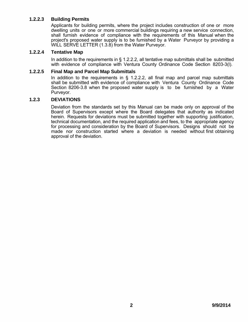
1.2.2.3 Building Permits Applicants for building permits, where the project includes construction of one or more dwelling units or one or more commercial buildings requiring a new service connection, shall furnish evidence of compliance with the requirements of this Manual when the project's proposed water supply is to be furnished by a Water Purveyor by providing a WILL SERVE LETTER (1.3.8) from the Water Purveyor.
1.2.2.4 Tentative Map
In addition to the requirements in § 1.2.2.2, all tentative map submittals shall be submitted with evidence of compliance with Ventura County Ordinance Code Section 8203-3(l).
1.2.2.5 Final Map and Parcel Map Submittals In addition to the requirements in § 1.2.2.2, all final map and parcel map submittals shall be submitted with evidence of compliance with Ventura County Ordinance Code Section 8206-3.8 when the proposed water supply is to be furnished by a Water Purveyor.
1.2.3 DEVIATIONS
Deviation from the standards set by this Manual can be made only on approval of the Board of Supervisors except where the Board delegates that authority as indicated herein. Requests for deviations must be submitted together with supporting justification, technical documentation, and the required application and fees, to the appropriate agency for processing and consideration by the Board of Supervisors. Designs should not be made nor construction started where a deviation is needed without first obtaining approval of the deviation.
2 9/9/2014
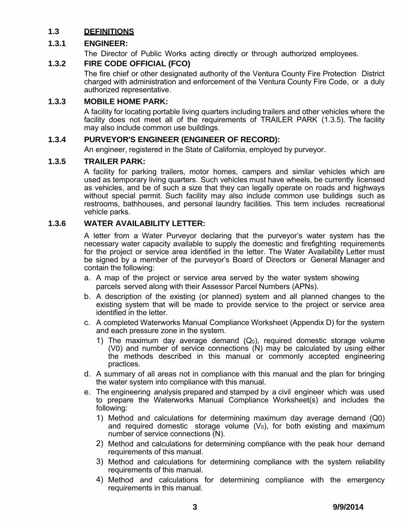
1.3 DEFINITIONS
1.3.1 ENGINEER: The Director of Public Works acting directly or through authorized employees.
1.3.2 FIRE CODE OFFICIAL (FCO) The fire chief or other designated authority of the Ventura County Fire Protection District charged with administration and enforcement of the Ventura County Fire Code, or a duly authorized representative.
1.3.3 MOBILE HOME PARK: A facility for locating portable living quarters including trailers and other vehicles where the facility does not meet all of the requirements of TRAILER PARK (1.3.5). The facility may also include common use buildings.
1.3.4 PURVEYOR'S ENGINEER (ENGINEER OF RECORD): An engineer, registered in the State of California, employed by purveyor.
1.3.5 TRAILER PARK: A facility for parking trailers, motor homes, campers and similar vehicles which are used as temporary living quarters. Such vehicles must have wheels, be currently licensed as vehicles, and be of such a size that they can legally operate on roads and highways without special permit. Such facility may also include common use buildings such as restrooms, bathhouses, and personal laundry facilities. This term includes recreational vehicle parks.
1.3.6 WATER AVAILABILITY LETTER:
A letter from a Water Purveyor declaring that the purveyor’s water system has the necessary water capacity available to supply the domestic and firefighting requirements for the project or service area identified in the letter. The Water Availability Letter must be signed by a member of the purveyor’s Board of Directors or General Manager and contain the following: a. A map of the project or service area served by the water system showing
parcels served along with their Assessor Parcel Numbers (APNs). b. A description of the existing (or planned) system and all planned changes to the
existing system that will be made to provide service to the project or service area identified in the letter.
c. A completed Waterworks Manual Compliance Worksheet (Appendix D) for the system and each pressure zone in the system. 1) The maximum day average demand (Q0), required domestic storage volume
(V0) and number of service connections (N) may be calculated by using either the methods described in this manual or commonly accepted engineering practices.
d. A summary of all areas not in compliance with this manual and the plan for bringing the water system into compliance with this manual.
e. The engineering analysis prepared and stamped by a civil engineer which was used to prepare the Waterworks Manual Compliance Worksheet(s) and includes the following: 1) Method and calculations for determining maximum day average demand (Q0)
and required domestic storage volume (V0), for both existing and maximum number of service connections (N).
2) Method and calculations for determining compliance with the peak hour demand requirements of this manual.
3) Method and calculations for determining compliance with the system reliability requirements of this manual.
4) Method and calculations for determining compliance with the emergency requirements in this manual.
3 9/9/2014

In the case of Water Purveyors classified as Urban Water Suppliers under the Urban Water Management Planning Act, the adoption of a current Urban Water Management Plan that has been accepted by the State Department of Water Resources will satisfy the requirement for submission to and acceptance by the County of a Water Availability Letter.
1.3.7 WATER PURVEYOR:
A public utility, a mutual water company, a governmental body, or other entity, owning and operating a water system and holding a valid permit to purvey water from the State Department of Public Health or Ventura County Environmental Health Division. In the case of a public utility, it must also hold a valid "certificate of convenience and necessity" from the California Public Utilities Commission.
1.3.8 WILL SERVE LETTER: A letter from a Water Purveyor declaring that the purveyor’s system will provide a water connection to the proposed project identified in the letter. A Water Purveyor must have a WATER AVAILABILITY LETTER (1.3.6) on file with the County before the County will accept a WILL SERVE LETTER from the Purveyor. The County will accept the WILL SERVE LETTER only if there is existing additional capacity shown in the WATER AVAILABILITY LETTER (1.3.6) that is not dependent on future improvements to the Water Purveyor’s system. The WILL SERVE LETTER must be signed by a member of the purveyor’s Board of Directors or General Manager and include a copy of the most recent WATER AVAILABILITY LETTER accepted by the County. The submission shall include an accounting of Will Serve Letters issued compared to number of unused services remaining in the Water Availability Letter.
4 9/22/2015
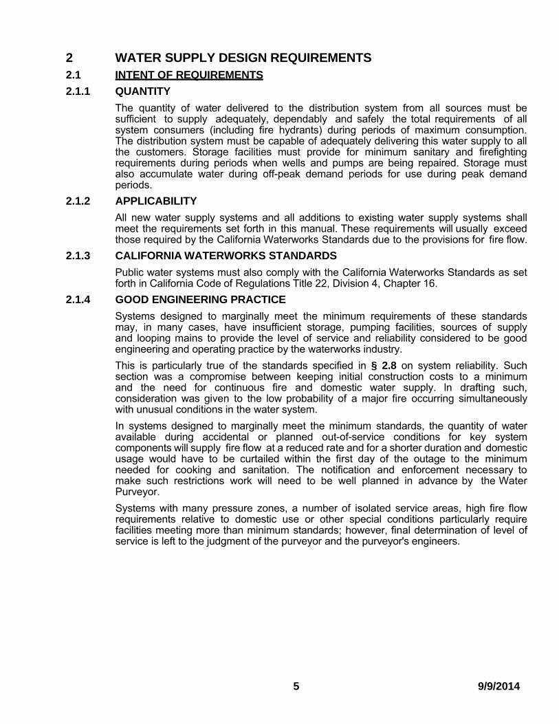
2 WATER SUPPLY DESIGN REQUIREMENTS 2.1 INTENT OF REQUIREMENTS
2.1.1 QUANTITY
The quantity of water delivered to the distribution system from all sources must be sufficient to supply adequately, dependably and safely the total requirements of all system consumers (including fire hydrants) during periods of maximum consumption. The distribution system must be capable of adequately delivering this water supply to all the customers. Storage facilities must provide for minimum sanitary and firefighting requirements during periods when wells and pumps are being repaired. Storage must also accumulate water during off-peak demand periods for use during peak demand periods.
2.1.2 APPLICABILITY
All new water supply systems and all additions to existing water supply systems shall meet the requirements set forth in this manual. These requirements will usually exceed those required by the California Waterworks Standards due to the provisions for fire flow.
2.1.3 CALIFORNIA WATERWORKS STANDARDS
Public water systems must also comply with the California Waterworks Standards as set forth in California Code of Regulations Title 22, Division 4, Chapter 16.
2.1.4 GOOD ENGINEERING PRACTICE
Systems designed to marginally meet the minimum requirements of these standards may, in many cases, have insufficient storage, pumping facilities, sources of supply and looping mains to provide the level of service and reliability considered to be good engineering and operating practice by the waterworks industry.
This is particularly true of the standards specified in § 2.8 on system reliability. Such section was a compromise between keeping initial construction costs to a minimum and the need for continuous fire and domestic water supply. ln drafting such, consideration was given to the low probability of a major fire occurring simultaneously with unusual conditions in the water system.
In systems designed to marginally meet the minimum standards, the quantity of water available during accidental or planned out-of-service conditions for key system components will supply fire flow at a reduced rate and for a shorter duration and domestic usage would have to be curtailed within the first day of the outage to the minimum needed for cooking and sanitation. The notification and enforcement necessary to make such restrictions work will need to be well planned in advance by the Water Purveyor.
Systems with many pressure zones, a number of isolated service areas, high fire flow requirements relative to domestic use or other special conditions particularly require facilities meeting more than minimum standards; however, final determination of level of service is left to the judgment of the purveyor and the purveyor's engineers.
5 9/9/2014
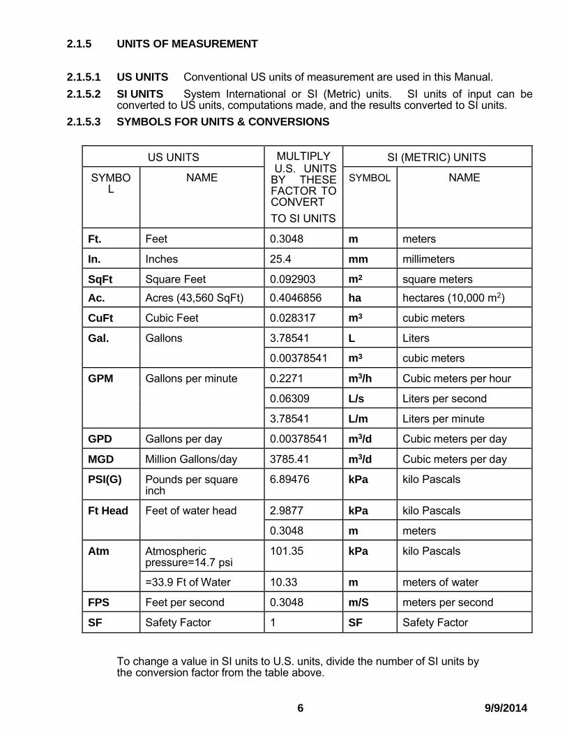
2.1.5 UNITS OF MEASUREMENT 2.1.5.1 US UNITS Conventional US units of measurement are used in this Manual.
2.1.5.2 SI UNITS System International or SI (Metric) units. SI units of input can be converted to US units, computations made, and the results converted to SI units.
2.1.5.3 SYMBOLS FOR UNITS & CONVERSIONS
US UNITS MULTIPLY U.S. UNITS
BY THESE FACTOR TO CONVERT
TO SI UNITS
SI (METRIC) UNITS
SYMBO L
NAME SYMBOL NAME
Ft. Feet 0.3048 m meters
In. Inches 25.4 mm millimeters
SqFt Square Feet 0.092903 m2 square meters
Ac. Acres (43,560 SqFt) 0.4046856 ha hectares (10,000 m2)
CuFt Cubic Feet 0.028317 m3 cubic meters
Gal. Gallons 3.78541 L Liters
0.00378541 m3 cubic meters
GPM Gallons per minute 0.2271 m3/h Cubic meters per hour
0.06309 L/s Liters per second
3.78541 L/m Liters per minute
GPD Gallons per day 0.00378541 m3/d Cubic meters per day
MGD Million Gallons/day 3785.41 m3/d Cubic meters per day
PSI(G) Pounds per square inch
6.89476 kPa kilo Pascals
Ft Head Feet of water head 2.9877 kPa kilo Pascals
0.3048 m meters
Atm Atmospheric pressure=14.7 psi
101.35 kPa kilo Pascals
=33.9 Ft of Water 10.33 m meters of water
FPS Feet per second 0.3048 m/S meters per second
SF Safety Factor 1 SF Safety Factor
To change a value in SI units to U.S. units, divide the number of SI units by the conversion factor from the table above.
6 9/9/2014

2.2 SYMBOLS
The following symbols are used repeatedly in the Manual.
DF Duration of required peak fire flow (minimum), in hours. See § 2.3.2.
F Fire flow rate, in GPM. See § 2.3.3.
M Multiplier for peak hour domestic flow rate. See § 2.3.1.
N Number of equivalent residential services in system or portion of system tributary to facility being designed. See § 2.3.4.
P Peak flow demand rate, in GPM. See § 2.5.2..
PE Peak flow demand rate during emergency conditions allowing reduced flow, in GPM. See § 2.8.2
PED Peak domestic flow demand rate during emergency conditions allowing reduced flow, in GPM. See § 2.8.2
PEF Peak fire flow demand rate during emergency conditions allowing reduced flow, in GPM. See § 2.8.2
QD Quantity of water supply for domestic use (minimum required) in GPD. See § 2.4.2
QF Quantity of water supply for fire (minimum required), in GPD. See § 2.4.2. QM Quantity of water supply (minimum required), in GPD. See § 2.4.2. Qo Quantity of water used on maximum day (average) from the table in § 2.3.5, in GPM.
Q1 Quantity of water supply actually available to system, in GPM. Where water supply is dependent on pumps without automatic control, Q1, shall be reduced by the capacity of the largest pump.
S Factor to give credit for storage in excess of minimum in determining required supply. See § 2.4.2.
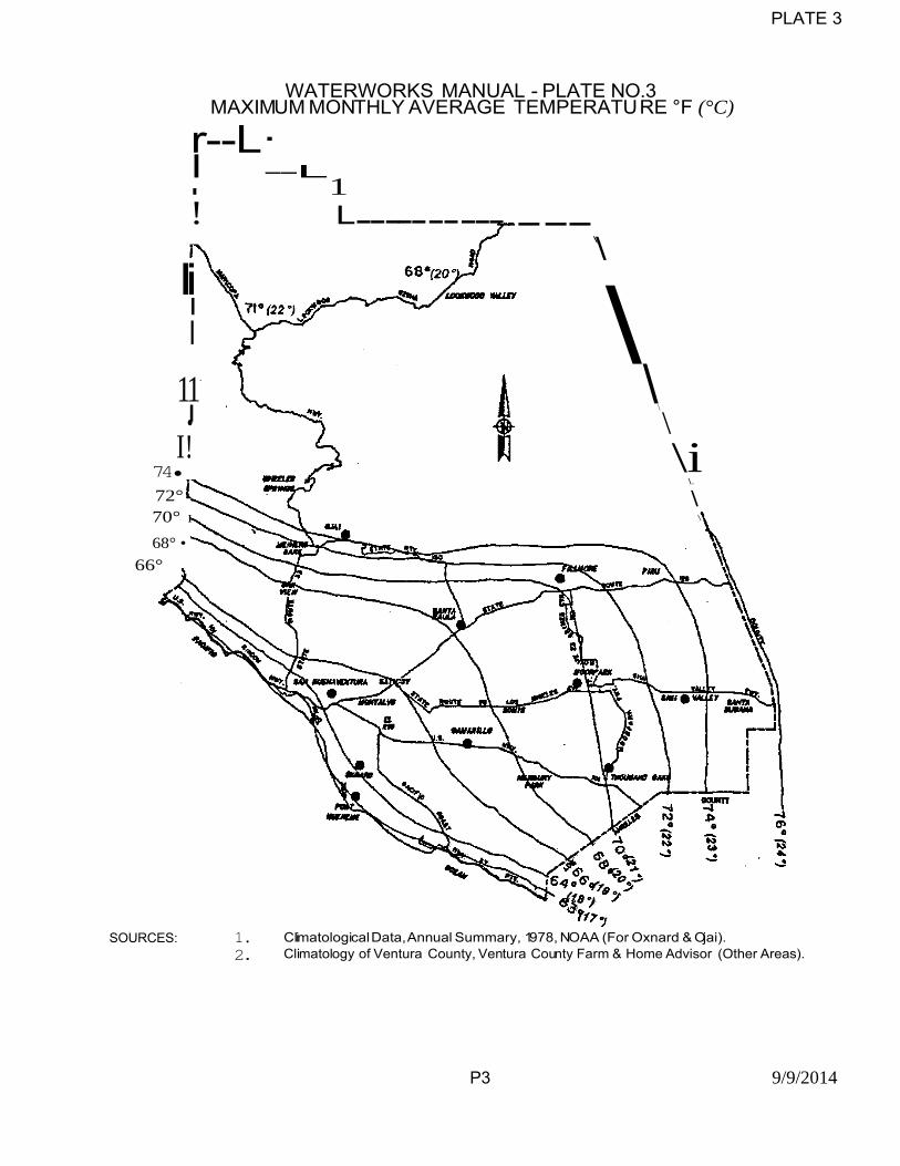
T Maximum average monthly air temperature in degrees Fahrenheit, 50º min., 80º max. See Plates 3 & 4.
VM Volume of storage (minimum required for minimum QM), in Gal. See § 2.7.2.
Vo Volume of storage quantity from the table in § 2.3.5, in Gal. V1 Volume of storage actually available in system, in gal. VE Volume of storage required as a minimum to provide for emergency conditions, in Gal.
See § 2.8.3.
VE1 VE2 Volume required during emergency periods. See § 2.8.
VF Storage capacity required for fire. See § 2.7.2.
2.3 NUMERICAL VALUES OF VARIABLES AND CONSTANTS
2.3.1 PEAK HOUR FLOW MULTIPLIER - "M"
M = 10.56 / N0.333, where "N" is less than 500
M = 1.33, where "N" is 500 or greater
N 1 2 3 4 5 10 25 50 100 200 300 400 500 M 10.6 8.4 7.3 6.7 6.2 4.9 3.6 2.9 2.3 1.8 1.6 1.4 1.3
7 9/9/2014

2.3.2 REQUIRED DURATION OF PEAK FIRE FLOW - "DF" for residential structures
see § 2.3.3.1 and “DF” for Commercial and Industrial structures see
Exhibit A in Appendix A on page A-1.
2.3.3 FIRE FLOW - "F"
2.3.3.1 RESIDENTIAL AREAS:
"F" shall be determined for each individual case by the Fire Code Official; however, in no case shall "F" be less than 1000 GPM. DF for residential areas shall be 2 hours. Exhibit A in Appendix A on page A-1 does not apply to residential areas.
Residential areas shall include one and two family residential lots, mobile home parks and lots with up to two acres of isolated commercial use when included in a predominantly residential area.
2.3.3.2 COMMERCIAL AREAS:
"F" shall be determined for each individual case by the Fire Code Official; however, in no case shall "F" be less than 1,250 GPM. See Exhibit A in Appendix A on page A-1 to determine “F” and “DF” for commercial areas.
Commercial areas shall include all commercial uses (except as noted under residential area), hotels, apartments, multiple residential buildings with three or more dwelling units, dormitories, all types of schools, and colleges.
2.3.3.3 INDUSTRIAL AREAS:
"F" shall be determined for each individual case by the Fire Code Official; however, in no case shall "F" be less than 1,500 GPM. See Exhibit A in Appendix A on page A-1 to determine “F” and “DF” for industrial areas.
2.3.3.4 TRAILER PARKS:
F = 500 GPM. DF = 2 hours.
"F" for recreation buildings in trailer parks shall be determined for each individual case by the Fire Code Official. Exhibit A in Appendix A on page A-1 does not apply.
2.3.3.5 ISOLATED RESIDENTIAL
F = 500 GPM at the building site.
The Fire Code Official may modify this requirement when, in his opinion, equivalent protection is provided by other means. Exhibit A in Appendix A on page A-1 does not apply.
Isolated residential shall mean a single, one-family dwelling on a parcel of land of 5 acres or more in size where no building is closer than 100 feet to the nearest building on any adjacent parcel.
8 9/9/2014

2.3.3.6 DEVIATIONS
The Fire Code Official is authorized to deviate from the requirements for individual proposed structures constructed to high standards of fire resistance which are contained in § 2.3.3.1 for any of the following reasons:
a. Existing residential lots that are within a portion of a Water Purveyor's current system's area and the full fire flow requirements cannot be met without excessive system modification and where equivalent protection is provided by installation of a residential fire sprinkler system in all new buildings.
b. New in-fill tract maps, with ten (10) or fewer parcels, within an existing Water
Purveyor service area, when the Water Purveyor certifies the system cannot provide the full fire flow, but can provide a minimum fire flow of 500 GPM with a residual pressure of at least 20 PSI, and where equivalent protection is provided by installation of a residential fire sprinkler system in each building on parcels within the tract map. Emergency power is required for all system components that require electrical power. This exception does not apply when the water system must be extended to the new proposed tract map or to new service areas
c. Parcel maps, with four or fewer parcels, when the Water Purveyor certifies the system cannot provide the full fire flow, but can provide a minimum fire flow of 500 GPM with a residual pressure of at least 20 PSI, and where equivalent protection is provided by installation of a residential fire sprinkler system in each building on parcels within the parcel map.
d. Parcel maps with four or fewer parcels, each 20 acres or more in size, where the Water Purveyor certifies that the system cannot provide the required fire flow or where there is no Water Purveyor, and where equivalent fire protection is provided by installation of automatic fire sprinklers in all buildings to be built within the parcel map area, and where adequate water to operate such sprinkler system is provided by any combination of on-site storage, well supplies or connections to a purveyor's system.
e. Upgrades to existing systems not in compliance with this manual serving primarily residential buildings and that have limited commercial areas within the service area may have the system supply and storage design based upon residential fire flow requirements when there is no new commercial development proposed in the area serviced by the system and additional supply capacity is provided based upon the commercial fire flow requirement. See § 2.3.3 Emergency power is required for all system components that require electrical power. For water systems constructed before October 1, 1980, the residential fire flow may be based upon 500 GPM. A request to use this deviation must be filed by the Water Purveyor and approved by the Fire Code Official.
f. The Fire Code Official is authorized to reduce the fire flow requirements for
isolated buildings or groups of buildings in rural areas or small communities where the development of full fire flow requirements is impractical. (Ref: VCFC Appendix B)
9 9/9/2014

2.3.4 NUMBER OF SERVICES "N" – Services for calculating water supply and/or demand. This is a separate term and distinctive from “service connections” or “meter.”
2.3.4.1 RESIDENTIAL AREAS:
Each single family dwelling or lot, each second dwelling unit, and each mobile home space of 3000 SqFt or more shall be counted as one service.
Each unit of an apartment, duplex or triplex building and each mobile home space under 3000 SqFt shall be counted as one-half service.
2.3.4.2 COMMERCIAL AND INDUSTRIAL AREAS:
Each acre (including storage and parking area) shall be counted as a minimum of five services.
2.3.4.3 AGRICULTURAL AREAS:
Each acre of land used exclusively for commercial agriculture shall be counted as two services. This may be modified by enforcing authority for storage and peak flow computation when system rules provide for scheduling irrigation on a rotational basis.
Residences, worker housing, dairies, processing facilities and similar uses shall be evaluated under the appropriate section of 2.3.4.
2.3.4.4 TRAILER PARKS:
Each trailer or trailer space shall be counted as one-third service.
2.3.5 MAXIMUM DAY AVERAGE DEMAND & REQUIRED STORAGE VOLUME - "Q0" & "V0"
All systems shall satisfy the requirements of the California Code of Regulations Title 22, Division 4, Chapter 16 for Maximum Day Demand (MDD) and Peak Hour Demand (PHD). In the absence of usage data, the following estimate may be used.
U.S UNITS = T in ºF, Q0 in GPM, V0 in Gal
N Q0 METERED Q0 UNMETERED
<20 (3.28+0.8N-1.09/N)(0.025T-0.45) (2.03+0.9N-0.76/N)(0.05T-1.5)
20-500 N(0.025T-0.45) N(0.05T-1.5)
>500 N(0.025T-0.45) N(0.05T-1.5)
N V0 METERED V0 UNMETERED
<20 1000(3.02+0.54N-1.58/N)(0.034T-0.7) 1000(3.82+0.67N-1.37/N)(0.05T-1.5)
20-500 1000(11+0.3N-50/N)(0.034T-0.7) 1000(20+0.33N-120/N)(0.05T-1.5)
>500 320N(0.034T-0.7) 1000(16+0.36N-100/N)(0.05T-1.5)
See Plate 3 or Plate 3A for Values of T.
Appendix E has plots of the U.S. units formulas for T = 65° & 75° for fast estimating.
10 9/9/2014
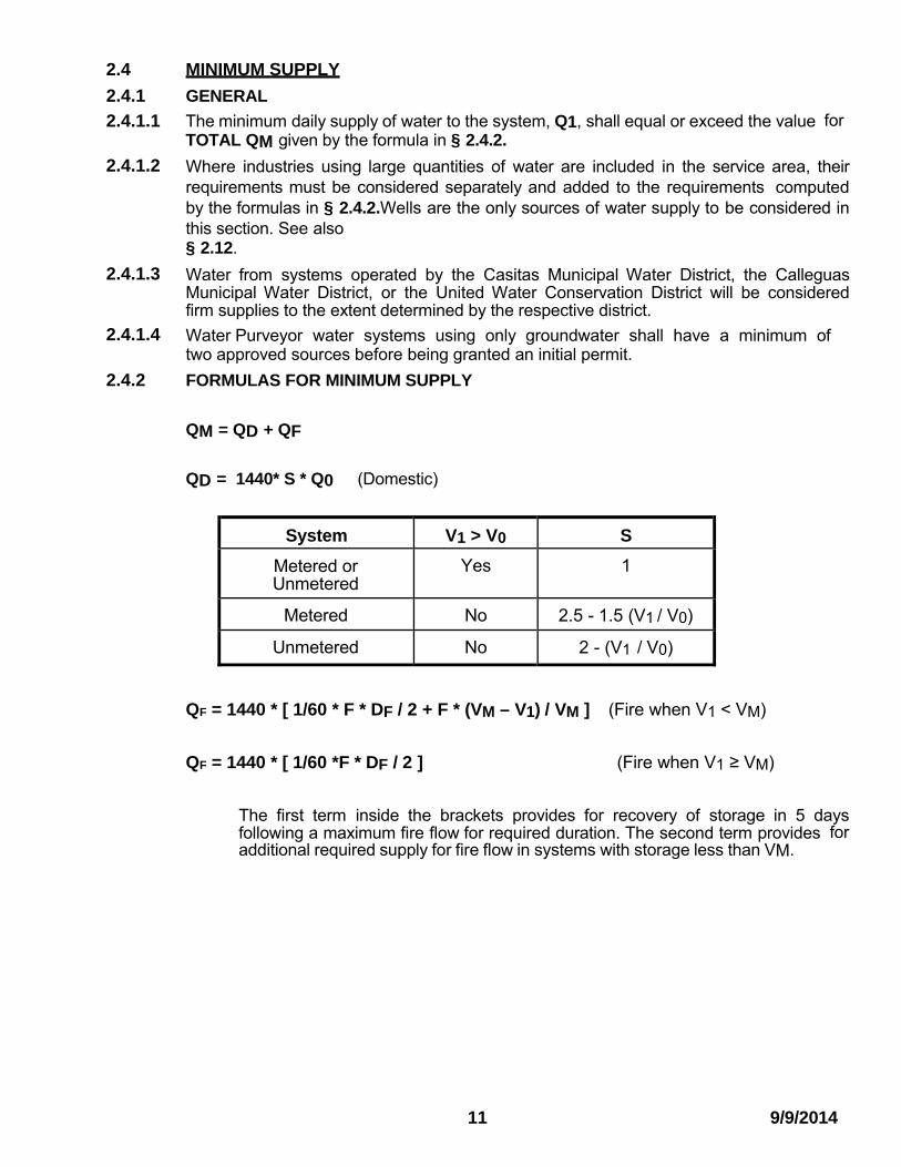
2.4 MINIMUM SUPPLY
2.4.1 GENERAL
2.4.1.1 The minimum daily supply of water to the system, Q1, shall equal or exceed the value for TOTAL QM given by the formula in § 2.4.2.
2.4.1.2 Where industries using large quantities of water are included in the service area, their requirements must be considered separately and added to the requirements computed by the formulas in § 2.4.2.Wells are the only sources of water supply to be considered in this section. See also § 2.12.
2.4.1.3 Water from systems operated by the Casitas Municipal Water District, the Calleguas Municipal Water District, or the United Water Conservation District will be considered firm supplies to the extent determined by the respective district.
2.4.1.4 Water Purveyor water systems using only groundwater shall have a minimum of two approved sources before being granted an initial permit.
2.4.2 FORMULAS FOR MINIMUM SUPPLY
QM = QD + QF
QD = 1440* S * Q0 (Domestic)
System V1 > V0 S
Metered or Unmetered
Yes 1
Metered No 2.5 - 1.5 (V1 / V0)
Unmetered No 2 - (V1 / V0)
QF = 1440 * [ 1/60 * F * DF / 2 + F * (VM – V1) / VM ] (Fire when V1 < VM)
QF = 1440 * [ 1/60 *F * DF / 2 ] (Fire when V1 ≥ VM)
The first term inside the brackets provides for recovery of storage in 5 days following a maximum fire flow for required duration. The second term provides for additional required supply for fire flow in systems with storage less than VM.
11 9/9/2014

2.5 PEAK DEMAND RATE
2.5.1 GENERAL
All systems shall satisfy the requirements of the California Code of Regulations Title 22, Division 4, Chapter 16 for Peak Hour Demand (PHD). That standard provides a methodology for determining PHD based on usage data. In the absence of usage data, the following estimate may be used.
2.5.1.1 The distribution system must be capable of delivering water at the rate determined by the formulas in § 2.5.2. Minimum sizes for individual pipelines shall be computed for flow given by the formulas using "N" for the portion of the system served by the pipeline.
2.5.1.2 In determining peak flow required by system, use highest value of "F" required in system.
2.5.1.3 Fire flows equal to or greater than the following quantities shall be capable of being obtained from any one fire hydrant in any area of that type.
TYPE AREA GPM
Residential 1000 (500 when approved by the FCO)
Commercial 1250
Industrial 1500
Trailer parks 500
Fire flows required in excess of the quantities shown above shall be capable of being obtained from any adjacent group of hydrants whose number shall be the minimum required to deliver the required fire flow at the rate per hydrant shown above. See Ventura County Fire Code for specific design requirements and limitations when using multiple hydrants to obtain required fire flow.
2.5.1.4 Mains and laterals serving a fire hydrant shall be at least 6" in diameter.
2.5.2 FORMULAS FOR PEAK HOUR FLOW RATES
P equals the larger of the values given by formula PA or PB below: PA = (M * Q0 / 2) + F
PB = M * Q0 2.6 PRESSURE
2.6.1 MINIMUM
A minimum of 20 PSI residual pressure shall be maintained in the mains at all locations in the distribution system during required periods of flow at peak demand rate.
Each new distribution system that expands the existing system service connections by more than 20 percent or that may otherwise adversely affect the distribution system pressure shall be designed to provide a minimum operating pressure throughout the new distribution system of not less than 40 pounds per square inch at all times excluding fire flow. The maximum static pressure shall not exceed 150 PSI.
2.6.2 NORMAL
Water distribution systems shall be designed to maintain normal operating pressures of not less than 25 PSI nor more than 125 PSI at the service connection. Variations in pressures under normal operations shall not exceed 50% of the average operating pressure. The average operating pressure shall be determined by computing the arithmetical average of at least 24 consecutive hourly pressure readings.
2.6.3 MATERIALS DESIGN
All pipe, valves, fittings and appurtenances shall be designed for a minimum working pressure of 150 PSI unless a higher working pressure is called for in this Manual or any referenced specification or actual conditions require a high working pressure.
12 9/9/2014

2.7 STORAGE
2.7.1 GENERAL
2.7.1.1 Storage units include surface reservoirs and tanks and elevated tanks.
2.7.1.2 Size of storage units shall be computed from the lowest withdrawal level to the overflow level.
2.7.1.3 Storage requirements may be satisfied by providing the entire required minimum storage volume capacity (VM) in storage units. All systems shall satisfy the storage requirements of the California Waterworks Standards, however, in no case shall the storage be less than VF.
2.7.2 FORMULA FOR STORAGE CAPACITY
VM = V0 + VF
VF = 60 * F * DF (Fire)
2.8 SYSTEM RELIABILITY
2.8.1 REQUIREMENTS
A water system, and each of its components, shall be designed to insure reliability of service. Systems, or portions thereof, which rely on pumps to provide flow to the system are vulnerable to utility interruptions, mechanical breakdown and maintenance downtime. To insure reasonable reliability of such systems, the system shall be designed to provide the peak flow rate "PE" specified in §2.8.2 and the total water volume of "VE1" or "VE2" specified in § 2.8.3 during the period when any one of the following is occurring.
2.8.1.1 Power Interruption. A one hour interruption of electric power to all system pumps. Provide for PE & VE1.
2.8.1.2 Pump Out of Service A four day "out of service" condition of any one pump in the system at one time. Provide for PE & VE2.
2.8.1.3 Source Interruption Where water source is one of those listed in § 2.4.1.3, temporary suspension of service as provided by the rules of the district supplying water. Provide for PE & VE2.
2.8.2 PEAK FLOW RATES DURING EMERGENCY PERIODS
PE equals the larger of PEF or PED in formulas below:
PEF = (M * Q0 / 4) + 0.75 F
PED = M * Q0 / 2
13 9/9/2014

2.8.3 TOTAL VOLUME REQUIREMENTS DURING EMERGENCY PERIODS
Formulas for emergency water volumes:
VE1 = 60 * PE
VE2 = V0 + 0.75 * 60 * F
2.8.4 REQUIRED DURATION DURING EMERGENCY PERIODS
Peak flow requirements of § 2.8.2 are rates of flow which must be sustained for a period of one hour during a power outage and the two to four hour period DF of § 2.3.2 during longer emergency situations.
Total volume requirements are the total amount of water to be served:
(1) during the one hour emergency and,
(2) during the one to four day type emergency periods.
The facilities provided for normal operations may provide for emergency situations but in most cases will require augmentation by extra facilities. To meet the emergency requirements, the total system facilities remaining in operation during emergency periods must include two or more of the following together with larger diameter pipe to reduce friction losses in some cases:
a. Water stored at an elevation which will provide service by gravity.
b. Duplex booster pump installations (for § 2.8.1.2).
c. Wells or low level storage utilizing pumps with two sources of power (gas fueled emergency generators + electric powered emergency generators, or electric powered emergency generators + hydrocarbon fueled emergency generators) and automatic power source transfer (for § 2.8.1.1).
d. Wells (with pumps and power supplies as in 2.8.4 c) not required to meet the basic supply requirements (for § 2.8.1.2 and § 2.8.1.3).
e. Water stored at an elevation that does not provide gravity service can be combined with above (for § 2.8.1.2 and §2.8.1.3).
f. Emergency standby connection to another water system (for § 2.8.1.2 and § 2.8.1.3).
2.9 SURGE CONTROL
Water systems shall be designed to avoid excessive surges (water hammer). Where there is the possibility of excessive surges, the design shall incorporate such devices as pump control valves, slow opening check valves or surge tanks to minimize surges.
2.10 BLOW-OFFS
Permanent blow-offs shall be installed at the end of each dead-end water main where stagnant conditions are likely to develop. They shall be designed to provide a minimum flushing velocity of 2 ½ feet per second in the main. Fire hydrants can be substituted for a blow-off.
14 9/9/2014

2.11 WATER MAIN VALVE LOCATIONS
Sufficient valves shall be provided on water systems to minimize inconvenience and sanitary hazards during repairs. In general, valves on water mains of 12 inches or less should be located such that water main lengths of not more than 1,000 feet can be isolated by valve closures.
2.12 CRITERIA FOR DEMONSTRATING A LONG TERM DOMESTIC
GROUNDWATER SUPPLY
2.12.1 GENERAL
Various County ordinances and regulations require a demonstration that the proposed domestic water supply for development is likely to be adequate for the expected useful life of structures (the “long term”). When the proposed domestic water supply for a development is to be provided by a water supply system having fewer than five service connections and is to be drawn from wells, the following criteria and procedures in 2.12.1 to 2.12.4 shall be used to demonstrate that the supply is “long term”. Although this method has traditionally been a reliable way to demonstrate a long-term domestic water supply, some wells evaluated under the method will go dry for reasons including drought, earthquake damage, poor well construction, mineralization of the well screen, etc. In connection with the issuance of a permit to operate a state small water system pursuant to Section 64211 of Title 22 of the California Code of Regulations, the following criteria and procedures shall be used in addition to all other applicable state and local regulations for the purposes of demonstrating the sufficiency of the system’s water supply when that supply is to be provided exclusively by wells. In any case, only potable groundwater shall be considered for the purpose of the demonstration.
2.12.2 CATEGORIES
A domestic groundwater supply is divided into two categories, Category 1 and Category 2 wells. These categories cover all potential wells in the County.
2.12.2.1 Category 1 wells are those wells located in areas of the County where the Public Works Agency determines that the sustained yield of water wells may not be adequate to meet minimum County standards, or where existing data is insufficient to assess groundwater availability, and therefore it is necessary to conduct site specific work to demonstrate availability of a long term domestic (potable) groundwater supply. Category 1 wells are often located in bedrock areas which may or may not be near the edge of groundwater basins. If data regarding groundwater availability is insufficient a well test is required.
15 9/9/2014

2.12.2.2 Category 2 wells are those wells located in the County where the presence of groundwater is documented by substantial data to meet the long term requirements of the project. Generally Category 2 wells are located within the groundwater basins listed in the County of Ventura’s Groundwater Section Annual Report. In order to determine if a well meets the Category 2 requirement, contact the staff of the Groundwater Section of the Ventura County Watershed Protection District. They will consider, and may request, the following information prior to determining if a well test is required:
a) location of the well in the groundwater basin (located centrally, or near the margin of a basin),
b) well construction information (casing size, depth, screen interval),
c) pump information (capacity, horsepower),
d) whether the proposed pumping is an increase or decrease of past pumping, and
e) whether or not the basin is in an overdraft condition and local groundwater level conditions.
If there is insufficient documentation that the groundwater resource can provide a long term water supply, the well is considered a Category 1 well and a well test is be required.
16 9/9/2014

2.12.3 CATEGORY 1 WELL TEST
To demonstrate that a Category 1 well is likely to be adequate for the long term, the applicant shall complete a well pump and recovery test (well test) of the proposed water supply well that meets the following requirements:
2.12.3.1 Well Test Procedures - The following procedures shall apply to the well test.
1) The well test shall be performed under the immediate supervision of a California Licensed Water Well or Pump Contractor, or a California Registered Civil Engineer or Geologist.
2) The County may inspect a well test in-progress at any time to observe testing methods and results. The County may also measure the water level in the test well prior to and / or within 15 days after the testing has been completed to verify the static water level.
3) The well test shall not be initiated until the well has been idle for a period of at least 72 hours and the water level has become static.
4) The Water Resources Division of the Public Works Agency shall be notified by the person who will supervise and certify the testing at least 48 hours prior to initiation of the well test. Call staff directly at (805) 654-2024 or (805) 654-2907. Prior notification is needed to insure that the testing is properly conducted so that retesting is not necessary, and so the County will have an opportunity to observe portions of the test.
5) Use of the current County test form to record test results is required. 6) If the pump breaks suction at any time during the pumping period, the test shall be
stopped and restarted after the well has again reached a static level. 7) The recovery portion of the well test shall begin immediately upon completion of the
pump test. Measurements of the water levels shall be recorded during the time they are returning to static level. The well test may be terminated prior to the required recovery period, if the groundwater level returns to the original static water level before the full recovery period has elapsed.
8) Test results shall be submitted to the County Water Resources Division of the Public Works Agency on the current Water Well Pump and Recovery Test recording form, along with any other pertinent information.
9) The depth of water in a well shall be determined by electrical sounder, airline or digitized sounding equipment. Tapes and acoustical sounding equipment are not acceptable.
10) The well test shall be conducted in accordance with Table 1, below. 11) Except as otherwise provided in § 2.12.3.1(12) and § 2.12.3.1(13), the level of use
listed in the first column of Table 1 that is applicable to any given well shall be determined by computing the total number of persons to be served by that well. The total number of persons to be served by a well shall be determined as follows:
a. Identify every separate structure having a water requirement that is to be served by the well. Structures are separate from each other if they do not share a common roof. A structure has a water requirement if it contains at least one water closet (commode) plus at least one faucet. The division of what would normally be a single structure into separate structures for the purposes of avoiding a water requirement (e.g., by placing the water closet in one structure and the faucet in the other) is not allowed.
b. Determine the number of bedrooms (as defined in Policy 6.2 of the County Environmental Health Division) for each of the identified structures.
c. Using Table 1, determine the number of persons associated with each of the identified structures.
d. Again using Table 1, determine the total number of persons to be served by the well. Examples are: a well serving two identified structures, one with three bedrooms and the other with two bedrooms, would serve seven persons; a well serving one identified structure with five bedrooms would serve six persons.
17 9/9/2014

2.12.3.1 Well Test Procedures - (Continued)
12) When the development is residential and the number of structures to be served by a well cannot be determined (e.g., when the development is a subdivision intended to create residential lots for sale as vacant land) the level of use shall be deemed to be two single family dwellings, each including three bedrooms (or four persons) for each lot served by the well.
13) When the development is industrial or commercial, the Public Works Agency shall determine on a case-by-case basis the appropriate level of use to be assumed for the well test. If that level of use is equivalent to one of the levels listed on Table 1, the well test specified for that level on Table 1 shall be conducted. If that level is higher than the highest level on Table 1, the Public Works Agency shall also determine on a case-by-case basis the maximum number of hours the well test is to be conducted and the minimum number of gallons that the well must produce during the test.
14) The output of two or more wells serving the same development may be combined for the purposes of the well test provided the following requirements are met:
a. A minimum flow of 5 GPM shall be maintained for each well for the entire time it is pumped; and
b. The wells are either all tested concurrently or they are each separated from any other well by at least 500 feet.
15) The minimum number of gallons specified in the last column of Table 1 is based upon the assumption that each person will require 100 gpd and each legal lot on which the structure or structures are located may require an additional 2,678 gpd for outside use. The gpd required for personal use is multiplied by a safety factor of 4.
i. For example (U. S. Units): the total required gpd for a two bedroom residence (3 persons) plus a one bedroom second dwelling unit (2 persons) located on a single lot would be 4678 gpd (5 persons x 100 gpd x 4(SF) + 2678 = 4678). In Table 1, the next to last column lists the total required gpd for various levels of use, and the last column lists that total rounded up to the nearest 100 gallons.
When a well to which Table 1 applies is to serve more than 8 persons, the last two columns of the table shall be adjusted in accordance with methodology specified in § 2.12.3.1(15), above.
18 9/9/2014

2.12.3.2 Well Test Pass-or-Fail Criteria. The following criteria shall be used to evaluate the well test.
(1) The well must produce the applicable minimum number of gallons specified in the last column of Table 1 within a maximum of 24 consecutive pumping hours. A minimum flow of 5 GPM shall be maintained for the entire time the well is pumped. A well that fails to meet the applicable minimum flow requirement at any time during the well test will not pass even if it produces the applicable minimum number of gallons within 24 hours.
(2) During the last hour of pumping, the water level in the well must remain static.
(3) A well, after 24 hours of rest, must fully recover to the before test water level. Instrumentation error will be considered in evaluating recovery.
Table 1 (U.S. Units)
Level of Use gpd
per
bdrm.
gpd
with
(SF)=4
gpd
for
Land
Total
gpd
Pump Test
min.
gallons
1 bedroom = 2 persons 200 800 2678 3478 3500
2 bedrooms = 3 persons 300 1200 2678 3878 3900
3 bedrooms = 4 persons 400 1600 2678 4278 4300
4 bedrooms = 5 persons 500 2000 2678 4678 4700
5 bedrooms = 6 persons 600 2400 2678 5078 5100
6 bedrooms = 7 persons 700 2800 2678 5478 5500
7 bedrooms = 8 persons 800 3200 2678 5878 5900
2.12.4 CATEGORY 2 WELL QUALIFICATIONS
A Category 2 well is documented to provide a domestic water supply that is adequate for the long term requirements of the project. To qualify a well as a Category 2 well, the applicant shall provide documentation that demonstrates that the well is located in a Category 2 area. If there is any uncertainty as to whether the well is located in a Category 2 area, the well shall be deemed a Category 1 well.
19 9/9/2014

3 MATERIALS 3.1 GENERAL REQUIREMENTS
Materials shall be chosen for their strength, durability and ease of repair and maintenance, with due consideration for dead and live loads, beam strength, resistance to corrosion and internal pressure.
3.2 STANDARD LAND DEVELOPMENT SPECIFICATIONS
All materials for which specifications are provided by the Ventura County SLDS shall meet those specifications. Where reference is made to SLDS and the SLDS does not contain the referenced number, refer to the same section number in the SSPWC as provided in § 0 of SLDS. Reference to a section number, such as 287-10, includes all sections with numbers containing 287-10 in their number.
3.3 ALTERNATE MATERIALS
The provisions of this Manual are not intended to prevent the use of any material or method of construction not specifically prescribed by this Manual if such alternate has been submitted to and has been approved by both the Engineer and Purveyor's Engineer.
The Engineer may approve such alternate if such alternate is found to be suitable for the purpose intended and at least the equivalent of that prescribed in this Manual in quality, strength, sanitation, durability, safety, and effectiveness.
The Engineer may require submission of a sample of such alternate material, together with a technical report which includes design data, report of physical and chemical analysis, and details of laboratory tests which have been performed by testing laboratories or standard groups (UL, AWWA, ASTM, ASA, etc.)
3.4 TRANSMISSION AND DISTRIBUTION WATER PIPE
The following types of pipe are approved for use for water mains and services three inches or more in nominal diameter.
3.4.1 ASBESTOS CEMENT Pipe shall comply with SLDS § 207-7.
3.4.2 CAST IRON AND DUCTILE IRON PIPE shall comply with SLDS § 207-9.
3.4.3 STEEL PRESSURE PIPE shall comply with SLDS § 207-10.
3.4.4 CONCRETE CYLINDER PIPE shall comply with SLDS § 207-4 and SLDS § 451.
3.4.5 REINFORCED CONCRETE PRESSURE PIPE shall comply with SLDS § 207-5.
3.4.6 POLYVINYL CHLORIDE (PVC) PIPE shall comply with SLDS § 207-17.
3.4.7 HIGH DENSITY POLYETHYLENE (HDPE) shall comply with AWWA Standard C906, NFS Standard 014 and ASTM Standard F714.
20 9/9/2014

FIRE FLOW REQUIRED §2.3.3 SLDS § 451-3 TYPE
Less than 1250 GPM A
1250 GPM to 3000 GPM B
Greater than 3000 GPM C
3.5 PIPE LINE APPURTENANCES
The following materials are approved for use as appurtenances on water systems.
3.5.1 WATER SERVICE CONNECTIONS shall comply with SLDS § 451-1.
3.5.2 VALVES AND APPURTENANCES shall comply with SLDS § 451-2.
3.5.3 FIRE HYDRANTS shall comply with SLDS § 451-3.
Fire hydrant types shall be selected as follows: 3.5.4 PIPE FITTINGS shall comply with SLDS §451-4.
3.5.5 PIPE FLANGES, COUPLINGS AND ADAPTERS shall comply with SLDS § 451-5.
4 INSTALLATION AND CONSTRUCTION
Installation and construction shall comply with SLDS § 306 and sections referenced therein and with any permit requirements of agencies in whose rights-of-ways installation is made.
5 STORAGE FACILITIES
5.1 DESIGN
Welded steel tanks, standpipes, reservoirs, and elevated tanks for water storage shall comply with "AWWA D100,” as applicable and with the foundation and seismic requirements of the building code.
5.2 REPAIRING
Inspection and repairing of steel tanks, standpipes, reservoirs, and elevated tanks for water storage shall comply with "AWWA D101".
5.3 PAINTING
Painting and repainting of steel tanks, standpipes, reservoirs, and elevated tanks for water storage shall comply with "AWWA D102" and the environmental requirements contained in State and Federal laws.
6 PUMPS
Deep-well vertical turbine and submersible pumps shall comply with "AWWA E101".
7 ELECTRIC MOTORS
Electric motors shall comply with "American Standard for Rotating Electrical Machinery, ASA C50", complete series.
21 9/9/2014

PLATE 1
WATERWORKS MANUAL PLATE NO. 1 FIRE HYDRANT INSTALLATION
12" Variable (See Improvement Plans)
Adjustable Valve Box
Cover Marked "WATER" Cl. Water Main
Pavement
Standard Bury
6" Pipe
P.C.Concrete Thrust Block For Bearing Surface Area, See Plate 2.
NOTES 1. All materials and installation shall conform to the applicable sections of the Ventura
County Waterworks Manual. 2. When installation is in roads without curbs, (Road Standards Plate B-7), fire hydrants
shall be located within the road right of way, three feet clear of the property line. An eight foot wide clear, level access to the fire hydrant across the roadside ditch shall be provided by the installation of a properly sized culvert and fill. A driveway adjacent to the fire hydrant may be used to provide the required access.
3. Fire hydrants shall not be closer than three feet from driveways, street trees, lighting standards, signs, or other obstructions.
4. See Road Standards Plate 0-10 for sidewalk widening where sidewalk is adjacent to curb.
5. No coupling is required where the distance between the valve and the bury is less than four feet.
P1 9/9/2014

THRUST BLOCK REQUIREMENTS
PLATE 2
TABLE II
SOIL TYPE SAFE BEARING LOAD IN Lbs/Ft2
Soft Clay 500
Sand 1000
Sand & Gravel 1500
Sand & Gravel Cemented with Clay 2000
Shale 5000
When soil analysis is available, use actual bearing capacity of soil.
EXAMPLE Given: Determine thrust block area for 90º bend for 8" Class 150 pipe in sand. Design: Pressure = 150 + 50 (test pressure) =200 PSI.
From Table I, thrust = 9300 LBS for 100 PSI. For 200 psi thrust = 18,600 LBS. From Table II, safe bearing pressure for sand is 1000 PSF. Area required = 18,600/1000 = 18.6 SF
P2 9/9/2014
TABLE I
THRUST AT FITTINGS IN POUNDS (N) AT 100 PSI WATER PRESSURE
PIPE SIZE INCHES
CLASS PSI
TEES LBS
90º BENDS LBS
45º BENDS LBS
22½BENDS LBS
4 100 1,720 2,440 1,320 660
150 1,850 2,610 1,420 720
200 1,850 2,610 1,420 720
6 100 3,560 5,030 2,720 1,380
150 3,800 5,370 2,910 1,470
200 3,800 5,370 2,910 1,470
8 100 6,140 8,680 4,700 2,380
150 6,580 9,300 5,040 2,550
200 6,580 9,300 5,040 2,550
10 100 9,380 13,270 7,190 3,640
150 10,750 15,200 8,240 4,170
200 10,750 15,200 8,240 4,170
12 100 13,330 18,860 10,240 5,170
150 15,310 21,640 11,720 5,940
200 15,310 21,640 11,720 5,940
14 100 17,930 25,360 13,740 6,960
150 20,770 29,360 15,910 8,060
200 20,770 29,360 17,880 8,060
16 100 32,210 32,820 17,880 9,000
150 26,880 38,010 20,590 10,430
200 26,880 38,010 20,590 10,430
\ I
\i
PLATE 3
WATERWORKS MANUAL - PLATE NO.3 MAXIMUM MONTHLY AVERAGE TEMPERATU RE °F (°C)
r--L· I --L I 1 ! L---------- ---
\ \ Ii I I
11 \\
• \ I!
74• \.
72° \ 70° I \
68° •
66°
SOURCES: 1. 2.
Climatological Data, Annual Summary, 1978, NOAA (For Oxnard & Ojai). Climatology of Ventura County, Ventura County Farm & Home Advisor (Other Areas).
P3 9/9/2014

PLATE 4
WATERWORKS MANUAL - PLATE 4
MAXIMUM AVERAGE MONTHLY AIR
TEMPERATURES
AT SELECTED VENTURA COUNTY LOCATIONS
Location Ref. Maximum Average Monthly Temperature ºF
Camarillo 2 67 Fillmore 2 70 Lockwood Valley 2 68 Moorpark 2 70 Newbury Park 2 68 Oak View 2 68 Ojai 1 74 Oxnard 1 65 Ozena 2 71 Piru 2 74 Point Mugu 2 63 Port Hueneme 2 64 Rincon 2 64 Santa Paula 2 68 Saticoy 2 66 Simi 2 73 Simi Hills 2 75 Somis 2 68 Thousand Oaks 2 71 Ventura 2 64
Not listed above - From Plate 3
References:
1. Climatological Data Annual Summary, 1978, National Oceanic and Atmospheric Administration. Data for departures from normal were algebraically subtracted from monthly data to get long-term mean and the month with the highest value used.
2. Climatology of Ventura County, Ventura County Farm and Home Advisor. Used where data did not appear in Reference 1. Maps showing isotherms for July Maximums and July Minimums were used and the data averaged & rounded up.
P4 9/9/2014

APPENDIX A
VENTURA COUNTY FIRE PROTECTION DISTRICT
2013 VCFC TABLE B105.1 The following Fire Flow and Duration table is reprinted from the Ventura County Fire Code and is subject to change with future fire code adoptions. Please contact the Fire District to confirm current requirements.
Table B105.1 applies to Commercial and Industrial buildings and lots. Table B105.1 does not apply to One and Two family dwelling units. EXHIBIT A Table B105.1 MINIMUM REQUIRED FIRE FLOW* AND FLOW DURATION FOR BUILDINGSa
a. Types of construction are based on the California Building Code.
b. Measured at 20 psi.
*A reduction in required fire-flow of up to 50 percent, as approved by the FIRE CODE OFFICIAL, is allowed when the building is provided with an approved automatic sprinkler system. The resulting fire-flow shall not be less than 1,250 gallons per minute for the prescribed duration as specified in Table B105.1. See the current Ventura County Fire Code for specific requirements and limitations.
GROUP U OCCUPANCIES: Fire flow for Group U Occupancies shall be as determined by the Fire Code Official. B105.1 TABLE does not apply. See current Ventura County Fire Code.
A1 9/9/2014

APPENDIX B
WATER-SEWER SEPARATION REQUIREMENTS CALIFORNIA CODE OF REGULATIONS § 64572. Water Main Separation.
(a) New water mains and new supply lines shall not be installed in the same trench as, and shall be at least 10 feet horizontally from and one foot vertically above, any parallel pipeline conveying:
(1) Untreated sewage,
(2) Primary or secondary treated sewage,
(3) Disinfected secondary-2.2 recycled water (defined in section 60301.220),
(4) Disinfected secondary-23 recycled water (defined in section 60301.225), and
(5) Hazardous fluids such as fuels, industrial wastes, and wastewater sludge.
(b) New water mains and new supply lines shall be installed at least 4 feet horizontally from, and one foot vertically above, any parallel pipeline conveying:
(1) Disinfected tertiary recycled water (defined in section 60301.230), and
(2) Storm drainage.
(c) New supply lines conveying raw water to be treated for drinking purposes shall be installed at least 4 feet horizontally from, and one foot vertically below, any water main. (d) If crossing a pipeline conveying a fluid listed in subsection (a) or (b), a new water main shall be constructed no less than 45-degrees to and at least one foot above that pipeline. No connection joints shall be made in the water main within eight horizontal feet of the fluid pipeline. (e) The vertical separation specified in subsections (a), (b), and (c) is required only when the horizontal distance between a water main and pipeline is less than ten feet. (f) New water mains shall not be installed within 100 horizontal feet of the nearest edge of any sanitary landfill, wastewater disposal pond, or hazardous waste disposal site, or within 25 horizontal feet of the nearest edge of any cesspool, septic tank, sewage leach field, seepage pit, underground hazardous material storage tank, or groundwater recharge project site. (g) The minimum separation distances set forth in this section shall be measured from the nearest outside edge of each pipe barrel. (h) With Department approval, newly installed water mains may be exempt from the separation distances in this section, except subsection (f), if the newly installed main is:
(1) less than 1320 linear feet,
(2) replacing an existing main, installed in the same location, and has a diameter no greater than six inches more than the diameter of the main it is replacing, and
(3) installed in a manner that minimizes the potential for contamination, including, but not limited to:
(A) sleeving the newly installed main, or
(B) utilizing upgraded piping material
Authority cited: Sections 116350, 116375 and 131200, Health and Safety Code. Reference: Sections 116275, 116375 and 131051, Health and Safety Code.
B1 9/9/2014

APPENDIX C
EXCERPTS FROM THE VENTURA COUNTY ORDINANCE CODE (2011)
- Documents to be submitted with tentative maps.
Each tentative map submitted to the Planning Division shall be accompanied by documents containing all of the following items, excepting only those items waived by the Planning Director:
(l) A description of the proposed method and plan for providing a permanent domestic water supply to each proposed lot together with the following:
(1) When the proposed water supply is to be provided by a public water system, as defined in Section 4010.1 of the Health and Safety Code, a letter ("Water availability letter") from the owner or operator of the proposed water system stating that water is currently available, or is expected to be available within the next three years, sufficient to provide a permanent domestic water supply to each such lot shall be submitted; and
(2) Regardless of whether the proposed water supply is to be provided by a public water system, when it is to be drawn exclusively from wells in areas where groundwater supplies have been determined by the Environmental Health Division or the Public Works Agency to be questionable or inadequate, a report that is prepared in accordance with procedures established by the Public Works Agency and the Environmental Health Division and that demonstrates the availability of a permanent domestic water supply to each lot for a period of at least 60 years shall be submitted;
8206-3.8 - Water supply certificate.
When the proposed water supply is to be provided by anything other than individual wells on each lot, there shall be submitted with the final map or parcel map a water supply certificate, on a form provided by the County and signed by the proposed water supplier, certifying that:
(a) Either of the following is true:
(1) A binding agreement has been entered into between the owner of the land and the water supplier, enforceable by the owner and the owner's successors in interest to the land, providing, on terms substantially the same as those given the water supplier's customers generally, for the connection to the water supplier's system of each lot proposed to be served by the water supplier; or
(2) Each lot proposed to be served by the water supplier will be served through an existing connection provided by the water supplier to the property; and
(b) A civil engineer, registered by the State of California, has determined that:
(1) The water supplier's system complies with the quality and quantity standards set forth in Title 22 of the California Code of Regulations and the connection of each proposed lot to such system will not cause any failure of such compliance; and
(2) The facilities of the water supplier's system, including the installation to be made in the proposed subdivision, meet or exceed the requirements set forth in the applicable Ventura County Improvement Standards and Specifications; and
(c) The portion of the improvement plans containing the design and specifications for subdivision sewer is satisfactory to the water supplier.
8206-3.9 - Approval of domestic water supply.
A statement from the Environmental Health Division of the Resource Management Agency approving the method of permanent domestic water supply and, if a water supply certificate is required by Section 8206-3.8, approving such certificate shall be submitted with the final map or parcel map.
C1 9/9/2014

a. Temperature in °F = degreesb. The System is metered. b. Maximum Day Average Demand (Q0) = GPM c. Required Storage Volume (V0) = Gal
a. Minimum Fire Flow (F) = GPMb. Minimum Fire Flow Duration (DF) = Hours
a. Domestic Storage Required (V0) = Gal b. Fire Storage Required (VF) = 60 * F * DF = Gal c. Total Storage Required (VM) = Vo + VF = Gal d. Actual Storage Available (V1) = Gal
County of Ventura Waterworks Manual Compliance Check Appendix D
Water Purveyor:
System or Zone:
1. Determine Number of Service Connections (N) Category Qty Value Total Section Comments a. Number of single residential homes or lots = 1.0b. Number of 2nd residential units ≤ 1,800 sf = 1.0 c. Number of 2nd residential units > 1,800 sf = 1.0 d. Number of mobile home spaces < 3,000 sf = 0.5 e. Number of mobile home spaces ≥ 3,000 sf = 1.0 f. Number of multifamily housing units = 0.5 g. Number of trailer or trailer park spaces = 0.3 h. Number of commercial and industrial acres = 5.0 i. Number of agricultural acres = 2.0
Maximum Service Connections (N) = Actual Service Connections Issued =
Connections Available =
2. Determine Maximum Day Demand (Q0) and Storage (V0) from N
3. Determine Minimum Required Fire Flow (F) and Duration (DF)
4. Determine Required Minimum Total Storage (VM)
5. Determine Minimum Required Total Supply (QM)
Section Comments
Section Comments
Section Comments
Section Comments
a. Actual Supply Available in the System (Q1) = GPD b. Storage Factor (S) = c. Domestic Supply Required (QD) = 1440 * S * Q0 = GPD d. Fire Supply Required (QF) = GPD e. Total Supply Required (QM) = QD + QF = GPD
6. Determine Minimum Required Peak Hour Demand (PHDM) Section Comments a. Peak Hour Demand Multiplier (M) =
b. PA = (M * Q0 / 2 ) + F = GPM c. PB = M * Q0 = GPM d. PHDM = greater of PA and PB = GPM e. Actual Peak Flow Rate (PHD1) = GPM
7. Determine Emergency Requirements (PE, VE1 and VE2) Section Comments a. PED = M * Q0 / 2 = b. PEF = (M * Q0 / 4) + 0.75 * F = GPM c. PE = the greater of PED and PEF = GPM d. VE1 = 60 * PE = Gal e. VE2 = V0 + 0.75 * 60 * F = Gal f. Power Interruption of 1 Hour
Peak Hour Demand (must be ≥ PE) = GPM Volume (must be ≥ VE1) = Gal
g. Pump Out of Service
Peak Hour Demand (must be ≥ PE) = GPM Volume (must be ≥ VE2) = Gal

WWM Compliance Check Sheet based on N-sheet 1 of 2 D1 9/9/2014
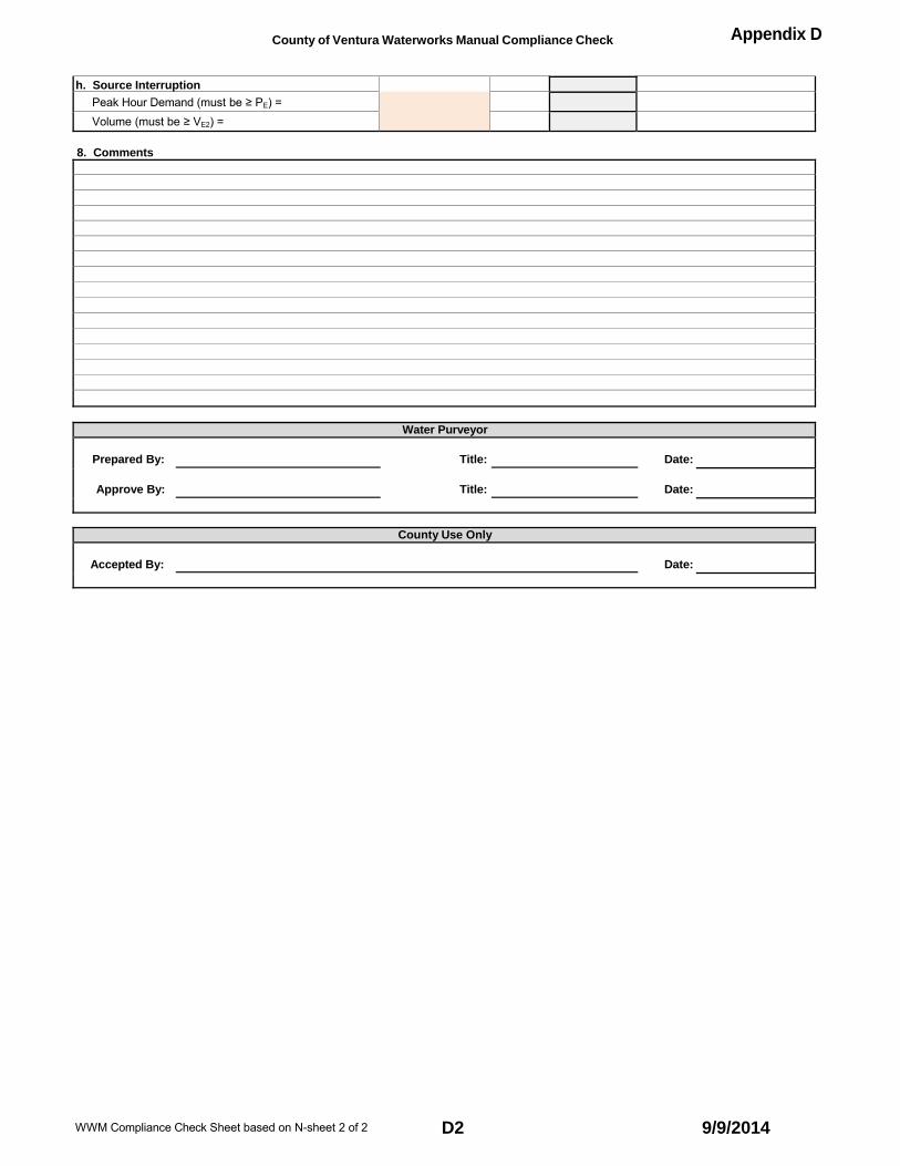
County of Ventura Waterworks Manual Compliance Check Appendix D
h. Source Interruption
Peak Hour Demand (must be ≥ PE) = Volume (must be ≥ VE2) =
8. Comments
Water Purveyor
Prepared By: Title: Date:
Approve By: Title: Date:
County Use Only
Accepted By: Date:
WWM Compliance Check Sheet based on N-sheet 2 of 2 D2 9/9/2014

a. Temperature in °F = degreesb. The System is metered. c. Maximum Day Average Demand (Q0) = GPM Use
d. Maximum Number of Service Connections (N) = Calculated N =e. Required Storage Volume (V0) in gallons = Calculated V0 =
a. Minimum Fire Flow (F) = GPMb. Minimum Fire Flow Duration (DF) = Hours
a. Domestic Storage Required (V0) = Gal
b. Fire Storage Required (VF) = 60 * F * DF = Gal c. Total Storage Required (VM) = Vo + VF = Gal d. Actual Storage Available (V1) = Gal
a. Actual Supply Available in the System (Q1) = GPD b. Storage Factor (S) = c. Domestic Supply Required (QD) = 1440 * S * Q0 = GPD d. Fire Supply Required (QF) = GPD e. Total Supply Required (QM) = QD + QF = GPD
County of Ventura Waterworks Manual Compliance Check Appendix D
Water Purveyor:
System or Zone:
1. Maximum Day Demand (Q0) from Analysis, Storage (V0) and N
2. Determine Minimum Required Fire Flow (F) and Duration (DF)
3. Determine Required Minimum Total Storage (VM)
4. Determine Minimum Required Total Supply (QM)
5. Determine Minimum Required Peak Hour Demand (PHDM)
Section Comments
Section Comments
Section Comments
Section Comments
Section Comments
a. Peak Hour Demand Multiplier (M) = b. PA = (M * Q0 / 2 ) + F = GPM c. PB = M * Q0 = GPM d. PHDM = greater of PA and PB = GPM e. Actual Peak Flow Rate (PHD1) = GPM
6. Determine Emergency Requirements (PE, VE1 and VE2) Section Comments a. PED = M * Q0 / 2 = b. PEF = (M * Q0 / 4) + 0.75 * F = GPM c. PE = the greater of PED and PEF = GPM d. VE1 = 60 * PE = Gal e. VE2 = V0 + 0.75 * 60 * F = Gal f. Power Interruption of 1 Hour
Peak Hour Demand (must be ≥ PE) = GPM Volume (must be ≥ VE1) = Gal
g. Pump Out of Service
Peak Hour Demand (must be ≥ PE) = GPM
Volume (must be ≥ VE2) = Gal h. Source Interruption
Peak Hour Demand (must be ≥ PE) = Volume (must be ≥ VE2) =
WWM Compliance Check Sheet based on Q-sheet 1 of 2 D3 9/9/2014

County of Ventura Waterworks Manual Compliance Check Appendix D
Water Purveyor:
System or Zone:
7. Comments
Water Purveyor Approval
Prepared By: Title: Date:
Approve By: Title: Date:
County Use Only
Accepted By: Date:
WWM Compliance Check Sheet based on Q-sheet 2 of 2 D4 9/9/2014

Qo
GP
M
Vo
Gal
lon
s
100,000
PLOTS OF FORMULAS IN §2.3.5 FOR METERED SERVICES
APPENDIX E
10,000
1,000 Qo MET ERED
Upper line is 75 F Lower line is 65 F
100
10
1
1 10 Number of Services ‐ N 100 1000 10000
10,000,000
1,000,000
100,000
Vo MET ERED Upper line is 75 F Lower line is 65 F
10,000
1,000 1 10 100 1000 10000
Number of Services - N

E1
9/9/2014

N
Vo
Gal
lon
s Q
o G
PM
APPENDIX E
PLOTS OF FORMULAS IN §2.3.5 FOR UNMETERED (FLAT RATE )SERVICES
100,000
10,000
1,000 Qo UNMET ERED Upper line is 75 F Lower line is 65 F
100
10
1
1 10 Number of Services -
100 1000 10000
10,000,000
1,000,000
Vo UNMET ERED Upper line is 75 F Lower line is 65 F
100,000
10,000
1,000 1 10Number of Services - N100 1000 10000
E2 9/9/2014