Embed Size (px)
Citation preview
Washington CountyOregon
WATER SYSTEM STANDARDS
February 2012Prepared by: Murray, Smith & Associates, Inc.
WATER SYSTEM STANDARDS
FOR
WEST SLOPE WATER DISTRICT
FEBRUARY 2012
Prepared By:
MURRAY, SMITH & ASSOCIATES, INC. 121 SW Salmon Street, Suite 900
Portland, OR 97204 (503) 225-9010


Page i
WATER SYSTEM STANDARDS
WEST SLOPE WATER DISTRICT
TABLE OF CONTENTS Section 1 - General Provisions Page 1.1 General Requirements ........................................................................................ 1 1.2 Definitions .......................................................................................................... 2 1.3 Guidelines for Design ......................................................................................... 2 1.4 Fire Flow Testing ................................................................................................ 4 1.5 Work in Public Rights-of-Way ........................................................................... 5 1.6 Operation of Valves in District’s Water System Prohibited ............................... 8 1.7 Acceptance of the Project ................................................................................... 8 Section 2 - Construction Specifications 050 General .............................................................................................................. 10 100 Trench Excavation and Backfill ....................................................................... 11 200 Surface Restoration ........................................................................................... 18 300 Ductile Iron Pipe and Fittings ........................................................................... 25 400 Hydrostatic Testing and Disinfection ............................................................... 37 500 Valves and Valve Boxes ................................................................................... 42 600 Fire Hydrants .................................................................................................... 45 700 Water Service Connections ............................................................................... 48 800 Air and Vacuum Release Valve Assembly ....................................................... 52 900 Precast Concrete Vaults .................................................................................... 55 Standard Details
No. 1 Typical Water Valve Location No. 3R Typical Valve Box Setting Detail No. 5R Valve Operator Extension No. 6 Hot Tap Detail No. 10 Typical Water Service Location No. 11 Typical Water Service Location for Multi-Unit Housing No. 12R 3/4” and 1” Water Service Installation No. 14R2 1-1/2” and 2” Service Installation No. 15 3” Meter Installation No. 16 4” Meter Installation No. 17 6” Meter Installation No. 20 Double Check Assembly Backflow Preventer No. 23 1” Reduced Pressure Backflow Preventer

Page ii
No. 25 1-1/2” and 2” Reduced Pressure Backflow Device No. 28 Double Check Detector Assembly No. 30 Trench Backfill Detail No. 40 Typical Thrust Block Detail No. 44 Gravity Thrust Block Detail No. 46 Collar Thrust Block on Ductile Iron Pipe No. 50 Typical Fire Hydrant Location No. 55R2 Standard Fire Hydrant Installation No. 60 Standard 2” Blow-off No. 64 6” Blow-off No. 66 Temporary Blow-off Assembly No. 70 Combination Air & Vacuum Valve Assembly No. 75 Standpipe Detail No. 80 Water Main Guard Post No. 90 Typical Pressure Gauge with Hose Bibb No. 95 Vault Ladder Installation Detail No. 96 Casing Detail
Appendix Receipt, Release and Waiver Washington County Utility Permit

SECTION 1 - GENERAL PROVISIONS

Page 1
SECTION 1 - GENERAL PROVISIONS 1.1 General Requirements
The following provisions, technical specifications and standard details set forth the requirements of the West Slope Water District for the construction of water system improvements. These design standards are intended to be used in conjunction with established District Policies as available through the District.
All plans for water system improvements must be prepared by an Engineer registered in the State of Oregon. Approval of the plans must be made by the District Engineer prior to construction. Any plans which have been approved by the District Engineer shall remain valid for a period of 1 year. If the project is not built within that time frame, the plan approval shall expire.
The District shall have the right to require any Contractor performing waterline related work within the District to have a minimum of three (3) years of continuous experience in waterline construction work and to have satisfactorily completed at least three (3) municipal waterline projects similar or greater, in size and scope, to the work specified.
Any permit required by state agencies shall be obtained by the person proposing the improvements. The applicant will apply for any permits required for work within the Washington County right-of-way (see the Washington County Permit Form in the appendix).
The District Representative shall have access to the project at all times and will make routine inspections. Should any of these inspections reveal that the construction of the water system improvements is not proceeding according to the approved plans or the specifications contained herein, the District Representative may order all work stopped and/or all defective work removed. If a revision is necessary, the District will receive revised plans of the project before allowing work to resume.
Upon completion of the project, the Engineer who prepared plans shall submit “As-Builts” of the work to the Water District and also certify that the work was constructed according to the plans and Specifications. If computer aided drafting systems are utilized in the design, submit electronic files in AUTOCAD .DWG or .DXF format saved to a version acceptable to the District. Also submit two (2) bond copies and one (1) mylar copy of the “As-Built” drawings. The plans should contain street names, centerlines, rights-of-way, public utility easements, lots and lot numbers, pipelines, fittings, meter locations, and contour lines with elevations.

Page 2
1.2 Definitions
The following terms used in these Design Standards have been identified and defined as indicated below:
A. “District” shall mean the West Slope Water District. B. “District Representative” shall mean any employee of the West Slope Water
District or consultant acting on behalf on the District.
C. “District Engineer” shall mean the registered engineer representing the West Slope Water District.
D. “Developer” shall mean any person, company, or corporation in the process of
developing property within the District.
E. “Contractor” shall mean any person, company, or corporation working with water related appurtenances within the District.
F. “Contract Documents” shall refer to the bound documents issued by the
Developer’s engineer for the bidding and/or construction of the project. G. “Drawings” shall refer to the full set of plan sheets from which the project is to
be constructed. H. “Work” shall refer to the furnishing of all materials, equipment, labor and
incidentals necessary to complete any individual pay item or the entire project as described herein and by the Contract Documents.
1.3 Guidelines for Design
The following are intended only as guidelines for the design of the water system improvements. The Developer’s engineer should meet with the District Representative prior to design to discuss the sizes of the mains and any other matters particular to the specific project. The District Engineer may require that modifications be made for each particular project. In general, the following guidelines shall be followed: A. All material shall be of new manufacture. No rebuilt, reconditioned, or used
material will be allowed. B. All pipe shall be Tyton push-on joint ductile iron pipe. C. Fittings shall be mechanical joint, unless otherwise specified.

Page 3
D. All rubber and gasket materials for underground service shall be Nitrile Butadiene Rubber (NBR or Buna-N).
E. Minimum main size will be 6 inches in diameter, except that 4-inch mains may
be permitted on runs less than 300 feet with no more than eight services at build-out, and when there is no possibility of future extensions.
F. Water mains shall normally be located 6 feet from face of curb on the south or
west side of the street. The Developer’s engineer is responsible for the design of the pipe to insure that 50% of the maximum pipe deflection is not exceeded.
G. Dead-end mains normally shall not be allowed, but when they are permitted, a
blow-off assembly shall be required. Dead-end mains shall extend just outside the edge of pavement to facilitate future extensions.
H. Water main extensions shall be required to continue to the boundaries of new
subdivisions. I. No fire hydrant shall be connected to a main less than 6 inches in diameter. J. Valves shall be located, whenever possible, at intersections. In general,
sufficient valves shall be provided to permit shutting down any section of the line, not exceeding 500 feet, with valve operations in not more than three locations.
K. Valves shall be installed in clusters at pipeline intersections. L. Valves 12 inches and smaller shall be gate valves. M. Valves 14 inches and greater shall be butterfly valves. N. Fire hydrants shall be located such that no part of any single-family residential
building is greater than 500 feet from a hydrant, and such that no part of any commercial, industrial, or multiple-family building is greater than 250 feet from a hydrant, both as measured along the most practicably accessible route. (These criteria are subject to change. Contact the Tualatin Valley Fire & Rescue Fire Marshall’s office for current information.)
O. Not used.
P. When it is not possible or practical to install the main within a dedicated public
street, an easement shall be provided. In general, a 15-foot wide easement will be adequate where vehicular access is not necessary, and a 20-foot wide easement will be required if vehicular access is necessary as determined by the

Page 4
District. The easement will so state that “any damage resulting from a mainline break in the easement will not result in liability to the District.”
Q. Any relocation work within existing right-of-way that is a requirement of the
development shall be performed by the Contractor at the Developer’s expense. R. Meters 2 inches and smaller shall be located in the street right-of-way at the
property line. Meters 3 inches and larger shall be located on the Developer’s property at the street right-of-way in a dedicated easement measuring 10 feet from each outside wall of the meter vault.
S. For design of public water system improvements, system hydraulics must be
analyzed using the worst case scenario envisioned in the District’s most current “Water System Master Plan”. The water system analysis shall be conducted using a simultaneous demand for the maximum (peak) day demand or peak hour non-fire demand, whichever is greater, and the fire demand. Parameters to be used to calculate non-fire demand shall be approved by the District. The fire demand shall be as specified by the Fire Marshall as applicable for the location, land use type, buildings contemplated and occupancy hazard.
All public water system improvements shall be designed to provide pressure within a range of no less than 40 pounds per square inch (psi) at peak demand (residual water system pressures at peak hour and peak day using network analysis modeling) excepting demand during fires and not greater than 100 psi. For practical application of the minimum 40 psi pressure requirement, a static pressure of 50 psi (theoretical pressure calculated from elevations or measured in the field) at non-peak times is required assuming a 10 psi drop during peak hour or peak day use. Exception may be granted or required by the District Representative from the 100 psi maximum pressure for extenuating circumstances, including topography, water demand requirements, system configuration, and system operation. Water system improvements shall also be designed to operate during a fire, to provide a system pressure of no less than 20 psi assuming a simultaneous peak day system demand. Required fire flow capacity of the public water system is to be designated by the Tualatin Valley Fire & Rescue Fire Marshall in conformance with the latest edition of the Uniform Fire Code.
1.4 Fire Flow Testing
The District shall be notified 48 hours in advance of anticipated fire flow tests to schedule such testing. Fire flow tests shall be conducted on all new water mains and fire lines installed within the District. Flushing hoses or nozzles used during the fire flow test shall not allow the flushing rate during the test to exceed 50% of the main line capacity unless otherwise approved by the District Representative.

Page 5
1.5 Work in Public Rights-Of-Way A. Agency Requirements
The Contractor shall have the water utility permit issued prior to construction of the water mains. Contractors shall comply with all rules and regulations of the City, State and County authorities regarding the closing of public streets or highways to the use of public traffic. No road shall be closed to the public, except by express permission of the affected regulating authority.
B. Protection of Existing Structures and Work
The Contractor shall take all precautions and measures necessary to protect all existing structures and Work. Tracked equipment will not be permitted on existing pavements. Adequate protective pads shall be used under outriggers of cranes or other equipment to prevent any marking, indentation or damage of any kind to existing pavements and work. Any damage to existing structures and Work shall be repaired by removing the damaged structure or work, replacing the structure and/or Work and restoring to original condition satisfactory to the District Representative.
C. Protection of Travelways
Contractors shall use every reasonable precaution to safeguard the persons and property of the traveling public. It shall be the sole responsibility of the Contractor to furnish, place, and maintain those barricades, barriers, lights, flares, danger signals, and flaggers as necessary to protect the persons and property of the traveling public. All barricades and obstructions shall be protected at night by signal lights, which shall be suitably distributed and operated from sunset to sunrise.
D. Work Hour Limitations
All work shall normally be conducted between the hours of 8:00 a.m. and 4:30 p.m. on non-national holiday weekdays only. No work on weekends or national holidays will be allowed. Requests for variations in work hours shall be made in writing and shall be approved by a District Representative.
E. Utility Interruption
In the event of interruption to domestic water, sewer, storm drain, or other utility services as a result of accidental breakage, or as the result of being exposed or unsupported, the Contractor shall promptly notify the proper authority. The Contractor shall also cooperate with said authority in restoration of the service as promptly as possible and bear all cost of repair. In

Page 6
no case shall interruption of any water or utility services be allowed to exist outside working hours, unless prior approval is received.
F. Site Clean-Up
The Contractor shall clean all spilled dirt, gravel, or other foreign material caused by construction operations from all streets and roads at the conclusion of each day’s operation. Within five days after completion of all paving and gravel shoulder resurfacing, remove all dirt, mud, rock, gravel, and other foreign material from the paved surface. Cleaning shall be by grader and front-end loader, supplemented by washing with water, power brushing, and hand labor.
G. Sanitation Facilities
Contractor shall provide and maintain sanitary facilities for their employees and their subcontractors’ employees that comply with the regulations of the local and state departments of health.
H. Land Monuments
The Contractor shall preserve or replace all existing federal, state, city, county, and private land monuments disturbed by their work. Replaced or reset monuments shall be of acceptable type and quality per appropriate jurisdictions’ requirements, placed in a manner consistent with recognized engineering and surveying practices.
I. Substitution of Materials
Whenever any material, article, device, product, fixture, form, type of construction, or process is indicated or specified by patent or proprietary name, by name of manufacturer, or by catalog number, such specifications shall be deemed to be used for the purpose of establishing a standard of quality and facilitating the description of the material or process desired. This procedure is not to be construed as eliminating from competition other products of equal or better quality by other manufacturers where fully suitable in design, and shall be deemed to be followed by the words “or as approved” or “or approved equal.” The Contractor may, in such cases, submit complete data to the District Representative for consideration of another material, type, or process which shall be substantially equal in every respect to the product so indicated or specified. Substitute materials shall not be used unless prior approved in writing.

Page 7
J. Water System Shutdown
Prior to scheduled shutdowns, the Contractor shall give one week advanced written notice to the District so the District may coordinate personnel and make preparations for the work. The written notice shall include the following information:
1. Location of shutdown. 2. Date scheduled for shutdown. 3. Number and location of existing valves required to be closed to isolate
work area. 4. Number and addresses of residents who will experience disruption to water
service by scheduled shutdown. 5. Contractor’s best estimate as to time required to complete work and resume
service to affected customers. The Contractor shall confirm shutdown operations (of the District’s system) with the District Representative 72 hours in advance. Water main shutdowns shall be limited to one shutdown per day. All shutdowns and changes of water supply shall be accomplished from 9:00 a.m. - 1:00 p.m., on Monday through Thursday. Shutdowns and changes of water supply shall be rescheduled if so directed by the District Representative. Shutdowns shall be limited to four hours in duration.
Contractor shall furnish all labor, materials, equipment and services necessary to accomplish the work in a manner satisfactory to the District Representative. All materials and equipment must be on site and inspected before shutdown. There is no guarantee that scheduled interruptions will not have to be rescheduled if the District Representative requires that the existing system be kept in operation. Any rescheduled interruptions shall be at no expense to the District. Tie-ins to the existing system shall not be permitted until the new systems have been constructed to the District Representative’s satisfaction, pressure tested, and disinfected with passing bacteriological test results.

Page 8
1.6 Operation of District Valves/Water System Prohibited
At no time shall the Contractor close off any lines, open any valves or take any other action which would affect the operation of the existing water system. Request approval at least one week in advance of the time that the interruption of the existing service is necessary.
1.7 Acceptance of the Project
The District will accept the water system improvements and provide water to the project upon completion of the following:
A. Compliance with the General Requirements specified herein. B. Installation of the materials and workmanship as described herein and per
District-approved Contract Documents. C. Successful hydrostatic pressure tests, as witnessed and approved by the District
Representative. D. Adequate flushing and chlorination of mains. E. Achieving satisfactory bacteriological test results from an Oregon Drinking
Water Program-approved laboratory. F. Testing and acceptance of all backflow preventers in accordance with Oregon
Health Authority and Agency Standards.
G. Dedication of any required easements or rights-of-way. H. Submittal of one set of red-lined plans (24 inches by 36 inches in size) with
referenced distances (i.e., swing-ties) between all permanent surface features of the water system. For example, reference the distance between the centerline of adjacent valve boxes. In addition, indicate reference distances to other permanent features such as sanitary manholes, storm drain manholes, power poles, etc.
I. Submittal of two (2) bond as-built sets and one (1) mylar as-built set of the
new system. If computer aided drafting systems are utilized in the design, submit electronic files in AUTOCAD .DWG or .DXF format in a version acceptable to the District.
J. Completion of final inspection of system and correction of any deficiencies
found during the final inspection. Contractor shall notify the District when all work and paving is complete to schedule final inspection.

Page 9
K. Approval and acceptance of all roadway related work by Washington County,
ODOT or other jurisdictional authority.
L. Submittal of a two-year warranty on the water system improvements for materials and workmanship beginning from the date of final acceptance of the project by the District. Contractor shall provide a maintenance bond in the amount of fifty percent (50%) of the final water system construction cost from a corporate surety approved by the District.

SECTION 2 - CONSTRUCTION SPECIFICATIONS

Page 10
SECTION 2 - CONSTRUCTION SPECIFICATIONS 050 GENERAL
A. The Contractor shall furnish all labor, materials and equipment required to complete all Work described herein and/or shown on Standard Details.
B. All materials supplied for Work described herein shall be of domestic
manufacture. C. All materials removed, unsuitable or in excess of those required for
construction shall become the property of the Contractor and shall be properly disposed of at Contractor’s own expense.
D. When references to the following abbreviations are made, they refer to
Specifications, Standards or Methods of the respective national association or governmental agency.
AASHTO American Association of State Highway Officials ACI American Concrete Institute AISC American Institute of Steel Construction AISI American Iron and Steel Institute ANSI American National Standards Institute ASTM American Society for Testing and Materials AWWA American Water Works Association DIPRA Ductile Iron Pipe Research Association ODOT Oregon Department of Transportation UBC Uniform Building Code UL Underwriter’s Laboratories
The following abbreviations contained in construction specifications will refer to these designated technical terms:
DI Ductile Iron (pipe) Flg Flange (fitting) fps Feet per second GI Galvanized Iron GV Gate Valve HMAC Hot Mixed Asphalt Concrete BFV Butterfly Valve MJ Mechanical Joint (fitting) PE Plain End (pipe) ppm Parts per million psi Pounds per square inch (pressure)

Page 11
100 TRENCH EXCAVATION AND BACKFILL PART 1 GENERAL 100.101 Scope of Work
This section covers the work necessary for the trench excavation and backfill, complete, except for pipe base and pipe zone backfill, which are included under the specification for the pipe.
100.102 Definitions
A. Bedding and Pipezone Backfill Bedding and pipezone backfill is defined as the furnishing, placing and compacting of material below, around and above the top of the pipe barrel to the dimensions shown on the Trench Backfill Detail, Standard Detail No. 30. The minimum depth for pipe bedding shall be 6 inches. The compaction requirement for the pipe bedding and pipe zone shall not be less than that required for the trench backfill above the pipe zone.
B. Trench Backfill
Trench backfill is defined as the furnishing, placing and compacting of material in the trench above the pipe zone, up to bottom of the pavement base rock, ground surface or surface material.
C. Bedding, Pipe Zone and Backfill Classification
Class A: Backfill with suitable native excavated material. Place the material in lifts with mechanical compaction sufficient to insure that no bridging occurs. Mound the excess material over the trench.
Class B: Backfill with suitable native excavated material. Place the material in lifts and mechanically compact to a relative density as shown on the plans or specified herein. Remove and dispose of excess material.
Class C: Backfill with suitable native excavated material. Place the material in the trench and water settle to a relative density as shown on the plans or specified herein. Remove and dispose of excess material.
Class D: Backfill with approved imported granular material. Place the material in lifts and mechanically compact to a relative density as shown on the plans or specified herein. Remove and dispose of excess material.

Page 12
PART 2 MATERIALS 100.201 Trench Backfill
A. Native Backfill Material
Native backfill material shall be select excavated native material free from roots or other organic material, trash, mud, muck, frozen material and large stones, processed as required, to be placed in the thicknesses prescribed and at the optimum moisture content to obtain the level of compaction required. When native excavated material is used for backfill around the pipe, it shall be free of rocks, cobbles, stones or other debris having a dimension greater than 1½ inches.
B. Granular Backfill Material
Granular backfill material shall be well-graded crushed rock with a maximum aggregate size of ¾-inch in the bedding and pipe zone, and a maximum aggregate size of 1 inch in the trench backfill zone. Crushed rock with ¾-inch minus and 1-inch minus gradation as shown on the plans shall meet the gradation and other requirements of the current Oregon Department of Transportation “Oregon Standard Specifications for Construction” for dense-graded Base Aggregate.
C. Sand
Sand shall be thoroughly washed and reasonably free of clay, loam, shale, alkali, vegetable matter, and other deleterious matter occurring either free or as a coating on the particles. The Contractor shall not mix sand from different geological sources.
D. Foundation Stabilization
Foundation stabilization material shall be 6-inch to 2-inch or 4-inch to 2-inch well-crushed gravel or crushed rock graded with less than 8 percent by weight passing the ¼-inch sieve, free from clay balls and organic debris as approved by the District Representative.
E. Water for Trench Backfill It will be the Contractor’s responsibility to make all arrangements for a source
of water and bear all costs for delivery of the water to the trench site.

Page 13
F. Compaction Equipment
Compaction equipment shall be of suitable type and adequate to obtain the densities specified. Compaction equipment shall be operated in strict accordance with the manufacturer’s instructions and recommendations and shall be maintained in such condition that it will deliver the manufacturer’s rated compactive effort.
PART 3 WORKMANSHIP 100.301 Pavement, Curb, and Sidewalk Removal A. Saw Cutting
Cut all bituminous and concrete pavements, regardless of the thickness, and all curbs and sidewalks, prior to excavation of the trenches, with an approved pavement saw, hydrohammer, or other approved pavement cutter. Width of the pavement cut shall be at least equal to the required width of the trench at ground surface or in conformance with Washington County and/or ODOT standards as applicable. Pavement and concrete materials removed shall be hauled from the site and not used for trench backfill.
B. Trench Width
The width of the trenches in which pipe is to be laid shall be 24 inches greater than the outside diameter of the pipe unless otherwise approved by the District Representative.
C. Grade
Carry the bottom of the trench to the lines and grades shown or established with proper allowances for pipe thickness and for gravel base or special bedding when required. Pipe will generally have a minimum 36 inches and a maximum 48 inches of cover. If the trench is excavated below the required grade, restore any part of the trench excavated below the grade with gravel of the type specified for pipe bedding. Place the gravel over the full width of the trench in compacted layers not exceeding 6 inches deep to the established grade, with allowance for the gravel base or special bedding.
100.302 Locating and Potholing Existing Utilities
The Contractor is solely responsible for potholing and/or hiring an independent locate company to locate all existing utilities and existing service lines to verify material types and locations. The Contractor shall be responsible for repairing all

Page 14
existing utilities and service lines damaged during the work. For work on private property, the Contractor shall provide all coordination with the property owner. Coordination with property owner shall include locating existing service lines and final locations of proposed service lines.
100.303 Shoring, Sheeting, and Bracing of Trenches
Whenever necessary to prevent caving during excavation in sand, gravel, sandy soil, or other unstable material or to protect adjacent structures, property, workmen, and the public, adequately sheet and brace the trench. Where sheeting and bracing are used, increase trench widths accordingly by the thickness of the sheeting. Keep trench sheeting in place until the pipe has been placed and backfilled through the pipe zone. Shoring and sheeting may be withdrawn and removed as the backfilling is done, but the Contractor shall be responsible for all damage to newly built Work and neighboring structures. Any construction sheeting and bracing which the Contractor has placed to facilitate his work may be ordered in writing by the District Representative to be left in place. All sheeting, shoring, and bracing of trenches shall conform to the safety requirements of the federal, state, or local public agency having jurisdiction over such matters. The most stringent of the requirements shall apply.
100.304 Location of Excavated Materials
During trench excavation, locate the excavated material within the construction easement, right-of-way or specified working area so that the excavated material will not obstruct any private or public traveled roadways or streets. Pile and maintain material from trenches so that the toe of the slope of the material excavated is at least 18 inches from the edge of the trench. It shall be the Contractor’s responsibility, however, to determine the safe loading of all trenches with excavated material.
100.305 Removal of Water
Provide and maintain ample means and devices with which to promptly remove and dispose of all water entering the trench excavation during the time the trench is being prepared for the pipe laying, during the laying of the pipe, and until the backfill through the pipe zone has been completed. These provisions shall apply during the noon hour as well as overnight.
Dispose of the water in an approved manner without damage to adjacent property. Drainage of trench water through the pipe under construction is prohibited. The pipe should be plugged so that no groundwater may enter at any time.

Page 15
100.306 Foundation Stabilization
When the existing material in the bottom of the trench is unsuitable for supporting the pipe, excavate below the flow line of the pipe, and backfill the trench to subgrade of the pipe base with “Foundation Stabilization” material previously specified herein.
100.307 Pipe Bedding
All pipe 4-inch nominal diameter and greater, all pipe under existing or future structures or roadways, and all pipe at a depth greater than 6 feet shall be laid in pipe bedding material. Unless otherwise noted on the plans, pipe or conduit of less than 4-inch diameter, outside structure lines and at a depth of less than 6 feet shall be bedded in native material properly shaped as specified below, all as detailed on the drawings. For service lines, bedding and pipe zone backfill material shall be sand.
Following the excavation of the trench, compacted pipe bedding material shall be placed the full width of the excavated trench to a depth as shown on the Trench Backfill Detail, Standard Detail No. 30. The bottom of the trench shall be accurately graded and rounded to fit the bottom quadrant of the pipe to provide uniform bearing and support for each section of pipe. Depressions for jointing shall be only of such length, depth and width necessary for the proper making of the joint.
100.308 Pipe Zone and Trench Backfill
A. All backfill shall be placed and compacted in 6- to 8-inch lifts. Backfill shall be carefully placed around the pipe and thoroughly compacted in 6- to 8-inch lifts or in a manner satisfactory to the District Representative so as to achieve the specified compaction requirements. Particular attention shall be given to the backfilling and tamping procedures to assure that no unfilled or uncompacted areas occur beneath the pipe. When placing pipe zone backfill, the Contractor shall prevent pipe from moving either horizontally or vertically during placement and compaction of pipe zone material.
B. Backfill Immediately: All trenches and excavations shall be backfilled
immediately after pipe is laid therein and necessary testing is complete, unless otherwise directed. Under no circumstances shall water be permitted to rise in unbackfilled trenches after pipe has been placed.
C. Where trenches are under existing or future structures, paved areas, road
shoulders, driveways or sidewalks, or where designated on the plans or specified elsewhere in these specifications, the trench backfill shall be Class D
Page 16
and pipe zone backfill shall be Class D. Class D backfill shall be compacted to 95 percent of maximum density at optimum moisture content as determined by AASHTO T-99, Method “D”.
D. Where trenches are outside existing or future structures, paved areas, road
shoulders, driveways or sidewalks, or where designated on plans or specified elsewhere, the trench backfill shall be Class B or Class D and pipe zone backfill in these areas shall be Class D. For these locations, compaction of Class B backfill shall be to not less than 90 percent of maximum density at optimum moisture content as determined by AASHTO T-99, Method “D”. Class D backfill shall be compacted to not less than 95 percent of maximum density at optimum moisture content as determined by AASHTO T-99, Method “D”.
100.309 Compaction Testing
A. Compaction tests will be required to show that specified densities of compacted backfill are being achieved by the Contractor’s compaction methods.
B. Tests of pipeline fill materials shall generally be made on each lift of fill for
every 100 feet of pipeline trench as measured along the pipe centerline, or as required by the appropriate jurisdiction’s road permit, whichever is more stringent. The Contractor shall provide the services of a licensed, independent agency to perform compaction testing.
100.310 Utility Crossings
A. Vertical clearance between the new pipe and existing utilities shall be 12 inches minimum unless otherwise noted on the plans or specified. Where existing utility lines are damaged or broken, the utility shall be repaired or replaced, care being taken to insure a smooth flow line and absolutely no leakage at the new joints. Unless otherwise specified herein, all expenses involved in the repair or replacement of leaking or broken utility lines that have occurred due to the Contractor’s operations shall be borne by the Contractor.
B. Water Lines Crossing Sewer Lines
Whenever water lines cross sewer lines, the Contractor shall comply with Oregon Administrative Rules (Chapter 333, Division 61) requirements for Public Water Systems. Wherever possible, the bottom of the water line shall be 1.5 feet or more above the top of sewer pipe and one full length of the water line pipe shall be centered at the crossing. For clearances less than 1.5 feet, the Contractor shall replace the existing sewer pipe with ductile iron or SDR 32.5
Page 17
PVC of equal size, or shall encase existing sewer pipe with concrete. New pipe or concrete shall extend a minimum of 10 feet on both sides of crossing.
C. Drainage Culverts
Replace drainage culverts which are removed. If the pipe is damaged during removal, dispose of it and furnish and install new pipe. Dispose of culvert pipe that is in too poor condition to replace because of age, physical condition, or other reasons beyond the Contractor’s control, and install new pipe at no cost to the District. Material for replacement shall be as specified in Section 200, “Surface Restoration,” included herein. Replace culvert pipe to the proper lines and grades. Do not replace culverts until the proposed water pipeline is installed and the proper backfilling of the trench has been completed to the subgrade of the culvert.
100.311 Settlement
A. Any settlement noted in backfill, fill, or in structures built over the backfill or fill within the two-year warranty period will be considered to be caused by improper compaction methods and shall be corrected at no additional cost to the District. Any structures damaged by excessive settlement shall be restored to their original condition by the Contractor.
B. Surplus excavated material shall be disposed of at designated spoil sites in a
legal manner, in full compliance with local jurisdictional requirements at no additional cost to the District.
100.312 Surface Restoration and Clean-Up
A. At the end of each work day, all open trenches shall be backfilled and all trenches within streets shall be temporarily paved or covered to the satisfaction of the District Representative. Temporary paving shall be replaced with permanent street paving, at completion of construction within street right-of-way or sooner if deemed necessary.
B. Contractor shall clean up and remove all excess materials, construction
materials, debris from construction, etc. Contractor shall replace or repair any fences, mailboxes, signs, landscaping, or other facilities removed or damaged during construction. Contractor shall replace all lawns, topsoil, shrubbery, flowers, and miscellaneous landscaping damaged or removed during construction. Contractor shall be responsible for seeing that lawns, shrubs, and miscellaneous landscaping remain alive and healthy for a period of 6-months and leave premises in condition equal to original condition before construction.
Page 18
200 SURFACE RESTORATION PART 1 GENERAL 200.101 Scope of Work
This section covers the work necessary for all required replacement of pavement, curbs, sidewalks, rock surfacing, and drainage facilities removed during construction. All provisions within this section are intended to be used in accordance with the appropriate standards of the governing roadway jurisdiction. In case of disagreement between codes or these specifications, the more restrictive shall prevail. In no case shall a lesser standard than those described below be employed without approval from the District Representative. The District Representative reserves the right to vary the classes of backfill and the type of resurfacing as best serves the interest of the District or County.
PART 2 MATERIALS 200.201 Aggregate Material
Base Course and Leveling Course: The aggregate material shall be a clean, well-graded crushed base aggregate conforming to the current edition of the Oregon Department of Transportation’s Oregon Standard Specifications for Construction. Base course shall be 1½-inch minus aggregate and leveling course shall be ¾-inch minus aggregate.
200.202 Asphalt Concrete Pavement
A. Hot Mix Asphalt Concrete
Use Level 3, ½-inch dense graded, PG 64-22 HMAC. Conform to the requirements as specified in Section 00744 of the Standard Specification.
B. Cold Mix Asphalt Concrete
Use cold mix asphalt concrete and ½-inch minus gradation with either MC 250 liquid asphalt, CMS-2, CMS-2S or CSS-1.

Page 19
C. Asphalt Prime Coat
Liquid asphalt for use as a prime coat under asphalt concrete shall be MC 250 liquid asphalt, CMS-2S or CSS-1.
D. Seal and Cover Coat
Asphalt material shall be CRS-2 cationic emulsified asphalt. Cover stone gradation shall conform to Type I – Parking Areas, Urban and Residential Streets, Airport Runways in the Oregon Department of Transportation’s Oregon Standard Specifications for Construction.
200.203 Concrete
Concrete for curbs, sidewalks, pavement, and miscellaneous construction shall conform to ASTM C 94, Alternate 3, and shall have a design mix proportioned for 3,000 pounds per square inch compressive strength at 28 days. Concrete mix shall contain no less than 5½ sacks of cement per cubic yard.
200.204 Concrete Forms
All forms for curbs and sidewalks shall be 2-inch dimensioned lumber, plywood, or metal forms. Forms on the face of the curb shall have no horizontal form joints within 7 inches of the top of the curb. All forms shall be approved by the District Representative.
200.205 Reinforcing Steel Conform to ASTM A 615, Grade 40. 200.206 Pipe for Storm Sewer and Culvert Replacement
Extra strength concrete pipe conforming to ASTM C 76, Class V for pipe 12 inches and under, and ASTM C 37, Class V for pipe greater than 12 inches, or as approved by the District Representative.
PART 3 WORKMANSHIP 200.301 Surface Restoration, General
A. All areas disturbed as a result of construction shall be restored to their original condition as nearly as possible or better. All excess material shall be removed from the site. Any damaged concrete walks or driveways shall be restored. All dirt and debris that accumulates from the Contractor’s operations shall be

Page 20
removed from inlets, catch basins, connecting pipelines and similar structures. Any material entering manholes or ditch culverts from street resurfacing and trenching work shall be removed. Daily clean-up of all visible mud and debris is required.
B. All open fields, unpaved public rights-of-way, or easements and other areas
not used as driveways, shall be restored by placement of 12 inches of topsoil, fine grading and hydroseeding to match existing conditions.
200.302 Pavement Material
Replace all pavement damaged from Work with asphalt concrete regardless of original type unless otherwise directed by the District Representative.
200.303 Removal of Pavement, Sidewalk, Curbs and Gutters
Removal of all pavement, sidewalks, curbs and gutters will conform to Section 100, “Trench Excavation and Backfill,” included herein.
200.304 Street Maintenance
Maintain all trenches as specified under Section 100, “Trench Excavation and Backfill,” included herein.
200.305 Aggregate Pavement Base
A. Pavement base shall be compacted to a minimum depth of 6 inches. Bring the top of the pavement base to a smooth, even grade at a distance below finished grade equivalent to the required pavement depth.
B. Compact the pavement base with mechanical vibratory or impact tampers to a
density of not less than 95 percent of the maximum density, as determined by AASHTO T-99, Method “D”.
200.306 Temporary Pavement
Where pavement is to be replaced, a temporary cold asphalt patch shall be applied within 24 hours of trench backfill. Before replacement of the permanent pavement, the Contractor shall continuously maintain the trenches in a condition acceptable to the responsible roadway agency.
200.307 Asphalt Concrete Pavement
A. Contractor shall conform to the requirements for prime coat and tack coat in the current edition of the Oregon Department of Transportation’s Oregon
Page 21
Standard Specifications for Construction. Tack coat all edges of existing pavement, manhole and clean out frames, inlet boxes and like items. When rate is not specified, asphalt will be applied at the rate of 0.1 gallon per square yard.
B. Asphalt Concrete Placement
1. Except as specifically modified herein, conform to the requirements for construction in the current edition of the Oregon Department of Transportation’s Oregon Standard Specifications for Construction. All trench cuts shall be kept in a smooth condition throughout the duration of the project.
2. The limits of the restoration shall include all damaged or undermined
surfacing. 3. Provide a smooth tee cut by sawcutting the existing pavement parallel to
the trench and beyond the sides of the trench excavation as shown on the plans. Remove any pavement which has been damaged or which is broken and unsound outside this area by making alternating traverse and parallel sawcuts. Parallel cuts must be a minimum of 25 feet long to minimize non-uniform pavement sections, unless otherwise directed by the District Representative. Provide a smooth, sound edge for joining the new pavement and sand seal edges.
4. Place the asphalt concrete to the specified depth on the prepared subgrade
over the trench. When depth is not specified, place asphalt concrete to the depth of the adjacent pavement, up to a maximum of 6 inches, at the direction of the District Representative. Minimum depth of pavement shall be 3 inches. When a prime coat is specified, place asphalt concrete after the prime coat has set. Maximum thickness for any one lift of pavement shall not exceed 2 inches. Spread and level the asphalt concrete with hand tools or by use of a mechanical spreader.
5. When the utility trench is placed closer than 3 feet inside the edge of
existing pavement, the remaining pavement must be removed and replaced with the trench repair. When the trench is under the existing edge of pavement, additional pavement shall be removed to allow a three foot minimum width of repair and to maintain the original street width. Contractor shall be aware that many roadway jurisdictions may require half street pavement overlays in lieu of, or in addition to, tee cuts. For construction contracts not issued by the District and if required by the roadway authority, this shall occur at no cost to the District.
Page 22
6. Settlement of ¼-inch or greater for asphalt concrete patches, occurring within two years of the completion of the projects acceptance by the District, shall require repair or replacement at the Contractor’s expense.
7. Surface Smoothness
The surface smoothness of the replaced pavement shall be such that when a straight-edge is laid across the patched area between the edges of the old surfacing and the surface of the new pavement, the new pavement shall not deviate from the straight-edge more than ¼-inch. For larger areas such as half-street paving, Contractor shall place a 12-foot straightedge parallel to and perpendicular to the roadway centerline as directed. The pavement surface shall not vary by more than ¼-inch.
8. Weather Conditions
Asphalt shall not be applied to wet material. Asphalt shall not be applied during rainfall, sand or dust storms, or any imminent storms that might adversely affect the construction. Asphalt concrete shall not be placed when the atmospheric temperature is lower than 40 degrees F., during heavy rainfall, or when the surface upon which it is to be placed is frozen or wet.
200.308 Concrete
A. Replace concrete driveways, sidewalks and curbs to the same section, width,
depth, line and grade as that removed or damaged. Saw broken or jagged ends of existing concrete on a straight line and to a vertical plane. Place new concrete only on approved, compacted base.
B. Replace concrete driveways and sidewalks between scored joints and make
replacement to prevent a patched appearance. Unless otherwise shown, provide a minimum 2-inch thick compacted leveling course of clean ¾-inch minus per Washington County Uniform Road Improvement Design Standards and the Oregon Department of Transportation’s Oregon Standard Specifications for Construction.
C. All replaced concrete driveways, sidewalks and curbs shall be constructed in
accordance with Washington County Uniform Road Improvement Design Standards and the Oregon Department of Transportation’s Oregon Standard Specifications for Construction.
Page 23
200.309 Rock Surfacing
Place rock surfacing only where directed by the District Representative on streets, driveways, parking areas, street shoulders, and other areas disturbed by the construction. Rock surfacing shall be 1-inch minus or ¾-inch minus crushed aggregate. Spread the rock surfacing to conform to adjacent existing grades and surfaces as directed. Compact with mechanical vibratory or impact tamper as directed.
200.310 Protection of Structures
Provide whatever protective coverings may be necessary to protect the exposed portions of the bridges, culverts, curbs, gutters, posts, guard fences, road signs, and any other structures from splashing oil and asphalt from the paving operations. Remove any oil, asphalt, dirt, or any other undesirable matter that may come upon these structures by reason of the paving operations.
Where water valve boxes, manholes, catch basins, or other underground utility appurtenances are within the area to be surfaced, the resurfacing shall be level with the top of the existing finished elevation of these facilities. If it is evident that these facilities are not in accordance with the proposed finished surface, notify the proper authority in order to have the facility altered before proceeding with the resurfacing around the obstruction, unless otherwise approved. Protect all covers during asphalt application.
200.311 Storm Sewers, Culverts, and Catch Basins
All storm sewers, catch basins, or culverts that are removed because of interference with new construction shall be removed in a manner allowing the least possible damage to the pipe or basin. Dispose of culvert pipe that is in too poor condition for reuse because of age, physical condition, or other reasons and install suitable pipe as specified in Section 200.206, “Pipe for Storm Sewer and Culvert Replacement,” included herein.
Replace all pipe on a 6-inch thick, ¾-inch minus crushed gravel base to the lines and grades established by the District Representative. Also replace culvert headwalls of all types to a condition at least equivalent to their original shape or form.
Reinstall catch basins in their original locations and reconnect to the drainage system in a manner equal to the original. If the existing catch basins are damaged beyond repair by the operations, construct new basins of similar size, cross section, and design as the original.

Page 24
200.312 Landscaping Restoration Restore all landscaped areas, yards and areas disturbed as a result of construction.
Replace all topsoil and removed landscaped material in-kind, and restore and replenish yard areas immediately upon completion of backfilling.
200.313 Dust Control
When the weather is dry and when, in the estimation of the District Representative, the dust becomes a nuisance, the Contractor shall sprinkle water on surface streets twice a day in order to keep the dust down and use a vacuum sweeper to remove dust producing material at no cost to the District. This sprinkling shall be maintained until the project is accepted. On paved streets when the backfilling has been completed, the streets shall be washed to remove all dirt and debris. If the dust becomes a nuisance before backfilling is completed the Contractor shall wash the streets to the satisfaction of the District Representative.

Page 25
300 DUCTILE IRON PIPE AND FITTINGS PART 1 GENERAL 300.101 SCOPE
This section covers the work necessary for furnishing and installing ductile iron pipe, fittings, and miscellaneous appurtenances.
PART 2 MATERIALS 300.201 General
A. Ductile iron piping materials and specials shall meet the specifications of this Section and of the appropriate AWWA Standard Specifications. In the case of conflict, the more stringent specifications shall apply.
B. Unless otherwise specified herein or shown on the plans, the minimum
pressure rating of all water works material specified herein shall be 1.5 times the operating pressure, or 150 psi minimum, whichever is greater.
C. All coatings and materials specified herein that come in contact with potable
water shall be National Sanitation Foundation (NSF) approved. 300.202 Ductile Iron Pipe
A. Ductile iron pipe shall conform to AWWA Standard C151 and shall be the standard push-on joint type or restrained joint. Push-on joints shall be “TYTON” type without exception. Ductile iron pipe shall be thickness Class 52. Polyethylene encasement, where required, shall conform to AWWA Standard C105.
B. Ductile iron pipe and cast iron fittings furnished shall be manufactured in the
United States of America. C. Ductile iron pipe shall be cement mortar lined, interior and exterior sealed in
accordance with ANSI/AWWA C104.A21.4. D. Push-on or mechanical type pipe joints shall conform to AWWA Standard
C111. Flanged ductile iron pipe shall conform to AWWA Standard C115.
Page 26
E. Restrained Joint Ductile Iron Pipe
1. Joint restraint for ductile iron pipe shall be accomplished with an integral lock mechanism except as may be otherwise specified.
2. Restraining components for pipe shall be ductile iron in accordance with
applicable requirements of ANSI/AWWA C110/A21.10 and/or C153/A21.53 with the exception of the manufacturer’s proprietary design dimensions. Push-on joints for such fittings shall be in accordance with ANSI/AWWA C111/A21.11.
The following is the approved list of restrained joint systems:
a. “Thrust-Lock”, Pacific States Cast Iron Pipe Company. b. “Fastite”, American Cast Iron Pipe Company. c. “TR Flex”, United States Pipe and Foundry Company. d. “Snap-Lok”, Griffin Pipe Products Company. e. “Megalug”, EBAA Iron, Inc. f. “Field-Lok”, United States Pipe and Foundry Company. g. “Super Lock”, Clow. h. “Restrained Joint”, McWane. i. “MJ-TJ” pipe with “Megalugs”, Pacific States Cast Iron Pipe Company. j. “Flex-Ring, American Cast Iron Pipe Company. j. “Lok-Ring”, American Cast Iron Pipe Company.
Where such a system may require “Megalugs” for restraint, “Megalugs”
shall be provided in quantities as may be required and shall be considered incidental to the joint restraint system.
3. Restrained joints for pipe shall be appropriately designed for the test water
pressure. F. No lengths of ductile iron pipe less than 3 feet in length will be allowed to be
installed in the District’s water system outside of valve and tee connections. 300.203 Fittings and Specials
A. Fittings
1. Fittings shall be mortar lined and seal coated. Mortar lining of fittings shall be factory installed only, unless otherwise approved by the District Representative. All fitting lining interior surfaces shall be smooth finished.

Page 27
2. Pipe fittings and specials used with ductile iron pipe shall be gray iron (cast iron) or ductile iron and shall conform to AWWA Standard C110. Ductile iron (compact) fittings conforming to AWWA Standard C153 may be substituted in lieu of AWWA C110 fittings for fitting sizes 3 inches through 24 inches in diameter. Fittings shall be mechanical joint, push-on type, flanged or plain-end as required and shown on the plans. Bolts shall be domestic Corten or ductile iron tee-head bolts.
3. When fitting joints are to be restrained, pipe joint restraint systems as
specified herein shall be used. 300.204 Flanges
Flanges shall conform to either ANSI/AWWA C207 Class D or ANSI B 16.5 150-lb class for 150 psi pressure rating and either ANSI/AWWA C207 Class E or ANSI B 16.5 150-lb class for pressure ratings between 150 and 275 psi. Flanges shall have flat faces and shall be attached with boltholes straddling the vertical axis of the pipe unless otherwise shown. Coordinate with pipe, valve and fitting suppliers to make certain that pipe, valve and fittings flanges match in bolt pattern.
Threaded flanges shall meet the requirements of AWWA Standard C115 and shall be installed only on pipe with a minimum Class 53 wall thickness. All flanged fittings shall be provided with bolts and gaskets as specified herein. The fittings shall be cement-mortar lined to the same thickness specified for pipe.
300.205 Gasket Materials A. All rubber gasket materials for underground service, including all valves,
fittings, and specials, shall be Nitrile Butadiene Rubber without exception. Standard Styrene Butadiene Rubber (SBR) gaskets are not acceptable for underground service, for any materials.
B. Gaskets for flanged joints shall be full faced. Ring gaskets shall not be
permitted. Gaskets shall conform to ANSI B16.21, suitable for the operating and test pressures of the pipe system. Gaskets shall be non-asbestos and non-phenolic compressed sheet packing with nitrile rubber binder. Gaskets shall be Garlock 3000, or equal.
300.206 Mechanical Couplings
Mechanical couplings, not a part of the pipe itself, shall be cast or ductile iron couplings in accordance with ASTM standard A-536 with Nitrile Butadiene Rubber rings and high strength alloy bolts and nuts conforming to ANSI/AWWA C111. Couplings shall be Dresser, Smith-Blair, or as approved.
Page 28
300.207 Tapping Sleeves
Tapping sleeves shall be stainless steel conforming to 18-8 Type 304 stainless steel with a CF 8 cast stainless steel flanged end with ANSI 150 lb drilling. Bolts and hardware to be Type 304 stainless steel and the branch outlet shall be heavy stainless steel pipe. The gasket shall be a full circumferential gasket. Tapping sleeve shall be JCM 432 or approved equal.
300.208 Casing Pipe, Carrier Pipe, Insulators, Sand and Seals A. Casing Pipe
1. Tunneled/bored/jacked casings shall be steel. Open trench installed casings shall be new class V, C76 reinforced concrete pipe with watertight joints conforming to ASTM C76 or steel.
2. Steel casing pipe shall be smooth steel in accordance with ASTM A283,
Grade C. The casing shall conform to ANSI/AWWA C200. The minimum wall thickness shall be as required by the jurisdiction governing the road, highway, railroad, or stream bed (for creek crossings) in question. In no case shall the casing wall thickness be less than ¼-inch. Casing section joints shall be field-welded full penetration butt weld joints. Each end of the casing for butt-welding shall be prepared by providing ¼-inch by 45 degrees chamfer on the outside edges.
B. Carrier Pipe
All pipe within casing shall be restrained joint ductile iron pipe as described in Section 300.202.
C. Casing Insulators The carrier pipe shall be installed with casing insulators banded to it for guides
and support. Insulators shall be a minimum of 12 inches wide. A minimum of two insulators shall be installed on each pipe length at a maximum spacing of 12 feet unless recommended otherwise by the manufacturer. The casing insulator shall be constructed of a heat-fused plastic epoxy coated steel band with built up PVC lining and multi-segmented to attach firmly around the pipeline. Insulator skids shall be sized to provide clearance of pipe bell coupling, or retainer gland and not more than 1½ inches of clearance from the top skids to the top of the casing. The casing insulators shall be Model M-12, as manufactured by Calpico, Inc. or approved equal. Insulators shall be sized to fit carrier pipe materials including any identified special coatings without damage.

Page 29
D. Sand
Sand filling of the annular space between the casing pipe and the carrier pipe is understood to be of fine dry clean sand of a single geologic source carefully air blown in the annular space of the casing.
E. Casing Seals
The casings shall be sealed using cement grout. The cement grout shall consist of one (1) part Portland Cement, three (3) parts clean, well graded sand and a minimum amount of water.
PART 3 WORKMANSHIP 300.301 Preparation of Trench
Before laying each section of the pipe, check the grade with a straight-edge and correct any irregularities found. The trench bottom shall form a continuous and uniform bearing area supporting the pipe on solid and undisturbed ground at every point between bell holes, except that the grade may be disturbed for removal of lifting tackle.
300.302 Bell (Joint) Holes
At the location of each joint, dig bell (joint) holes of ample dimensions in the bottom of the trench and at the sides where necessary to permit the joint to be made properly and to permit easy visual inspection of the entire joint.
300.303 Removal of Water
Provide and maintain ample means and devices at all times to remove and dispose of all water entering the trench excavation during the process of pipe laying.
300.304 Installation of Pipeline
A. Ductile iron pipe shall be installed in accordance with the most current version
of AWWA Standard C600. The methods employed by the Contractor in the storage, handling, and installation of pipe, fittings, valves, hydrants, equipment and appurtenances shall be such as to insure that the material, after it is placed, tested and permanently covered by backfilling is in as good a condition as when it was shipped from the manufacturer's plant. Should any damage occur to the material, repairs or replacement shall be made to the satisfaction of the District Representative.
Page 30
B. Sanitary Sewer Separation: See Section 100, Trench Excavation and Backfill, for discussion.
300.305 Distributing Pipe
Distribute material on the job from the cars, trucks, or storage yard no faster than can be used to good advantage. In general, distribute no more than one week’s supply of material in advance of the laying.
300.306 Handling Material
Provide and use proper implements, tools, and facilities for the safe and proper prosecution of the work. Lower all pipe, fittings and appurtenances into the trench, piece by piece, by means of a crane, slings, or other suitable tools or equipment, in such a manner as to prevent damage to the pipeline materials and protective coatings and linings. Do not drop or dump pipeline materials into the trench.
300.307 Cleaning Pipe and Fittings
Remove all lumps, blisters, and excess coal-tar coating from the bell and spigot ends of each pipe. Wire brush the outside of the spigot and the inside of the bell and wipe clean, dry, and free from oil and grease before the pipe is laid. Wipe the ends of mechanical joint pipe and fittings and of rubber gasket joint pipe and fittings clean of all dirt, grease, and foreign matter. Check interior of pipe for obstructions or debris and remove from pipe if found.
300.308 Placing of the Pipe in the Trench
Do not allow any foreign material to enter the pipe while it is being placed in the trench. If it is necessary to place pipe in such a manner that bedding material may enter pipe, due to trench configuration or shoring detail, 8-inch deep masonry plugs or tight woven canvas boots shall be placed on pipe ends and removed when placing pipe.
300.309 Push-On Joint Pipe
After the first length of push-on joint pipe is installed in the trench, secure pipe in place with approved backfill material tamped under and along sides to prevent movement. Keep ends clear of backfill. After each section is joined, place backfill as specified to prevent movement.
300.310 Mechanical Joint Pipe
Installation of mechanical joint pipe shall be as specified in AWWA C111 Appendix A, including bolt torque ranges.

Page 31
300.311 Cutting Pipe A. Cut pipe for inserting valves, fittings, or closure pieces in a neat and
workmanlike manner without damaging the pipe or lining and so as to leave a smooth end at right angles to the axis of the pipe. Cut pipe with milling type cutter or saw. Do not flame cut.
B. Dress cut ends of push-on joint pipe by beveling, as recommended by the
manufacturer. 300.312 Bell End to Face Direction of Laying
Unless otherwise directed, lay pipe with bell end facing in the direction of the laying. For lines on steep slopes, face bells upgrade only, as requested by the District Representative.
300.313 Permissible Deflection of Joints
Wherever it is necessary to deflect pipe from a straight line either in a vertical or horizontal plane, to avoid obstructions, or where long radius curves are permitted, the amount of deflection allowed shall not exceed the values in the following table:
ALLOWABLE INSTALLED DEFLECTION PERMITTED*
(18-Foot Length Pipe)
Allowable Mechanical Joint Deflection *
Allowable Push-On Joint Deflection**
Pipe Diameter (Inches)
Deflection Angle (Degrees & Minutes)
Deflection (Inches)
Deflection Angle (Degrees)
Deflection (Inches)
4 6º38´ 25 4 15 6 5º41´ 22 4 15 8 4º16´ 16 4 15
10 4º16´ 16 4 15 12 4º16´ 16 4 15
*The allowable deflection shall be whichever is less, the table values or those recommended by the pipe manufacturer. **Safe deflection for 150 pounds pressure. For higher pressure, reduce tabulated deflection 10% for each 150 pounds of added pressure.

Page 32
300.314 Alignment
Pipelines intended to be straight shall not deviate from the straight line at any joint in excess of 1 inch horizontally or vertically.
300.315 Unsuitable Conditions for Laying Pipe
Do not lay pipe in water or when, in the opinion of the District Representative, trench conditions are unsuitable.
300.316 Joining Push-on Joint Pipe and Mechanical Joint Fittings
Lay and join pipe with push-on joints in strict accordance with the manufacturer’s recommendations. Provide all special tools and devices, such as special jacks, chokers, and similar items required for the installation. Lubricant for pipe gaskets shall be furnished by the pipe manufacturer, and no substitutes will be permitted under any circumstances.
Mechanical joint fittings vary slightly with different manufacturers. Install the particular fittings furnished in accordance with the manufacturer’s recommendations. In general, the procedure shall be as hereinafter specified. Clean the ends of the fittings of all dirt, mud, and foreign matter by washing with water and scrubbing with a wire brush, after which, slip the gland and gasket on the plain end of the pipe. If necessary, lubricate the end of the pipe to facilitate sliding the gasket in place. Then guide the fitting onto the spigot of the pipe previously laid.
300.317 Thrust Restraint
A. All tees, plugs, caps, bends, offsets, as well as other appurtenances which are subject to unbalanced thrust, shall be properly braced with concrete thrust blocks. The concrete blocking shall bear against solid undisturbed earth at the side and bottom of the trench excavation and shall be shaped so as not to obstruct access to the joints of the pipe or fittings. Concrete thrust blocks shall be as shown in Standard Details No. 40, 44 and 46.
B. The Contractor shall provide internal or external joint restraint systems in lieu
of thrust blocks at the fittings and on all joints within appropriately designed restrained lengths for the test water pressure on each side of the fitting or joint. The Developer can design and submit calculations for thrust restraint according to the provisions of the Ductile Iron Pipe Research Association (DIPRA) current edition of the Thrust Restraint for Ductile Iron Pipe technical publication. If these calculations are not submitted to the District, then the

Page 33
restrained length values shown in the following tables shall be used based on the operating pressure in the line.
RESTRAINED LENGTHS FOR COMMONLY USED FITTINGS
Values for waterlines with operating pressure of 100 psi and less
Fitting
Pipe Diameter (in) 4 6 8 10 12
Bare (ft)
Poly (ft)
Bare (ft)
Poly (ft)
Bare (ft)
Poly (ft)
Bare (ft)
Poly (ft)
Bare (ft)
Poly (ft)
11¼° Vertical Bend, Down 4 6 6 9 8 11 9 13 11 16 11¼° Horizontal Bend 1 2 2 2 3 3 3 4 4 4 22½° Vertical Bend, Down 8 12 12 17 16 22 19 27 22 32 22½° Horizontal Bend 3 3 4 5 5 6 7 7 8 9 45° Vertical Bend, Down 18 25 25 36 33 46 40 57 47 67 45° Horizontal Bend 6 7 9 10 11 12 14 15 16 18 90° Vertical Bend, Down 42 61 60 86 79 112 96 137 112 161 90° Horizontal Bend 15 16 21 23 27 30 33 36 38 43 Dead End 28 40 40 57 52 74 63 90 75 107
RESTRAINED LENGTHS FOR VARIOUS USED FITTINGS
Values for waterlines with operating pressure between 100 and 150 psi
Fitting
Pipe Diameter (in) 4 6 8 10 12
Bare (ft)
Poly (ft)
Bare (ft)
Poly (ft)
Bare (ft)
Poly (ft)
Bare (ft)
Poly (ft)
Bare (ft)
Poly (ft)
11¼° Vertical Bend, Down 6 9 9 13 12 17 14 20 17 24 11¼° Horizontal Bend 2 2 3 3 4 4 5 5 6 6 22½° Vertical Bend, Down 13 18 18 26 23 23 29 41 34 48 22½° Horizontal Bend 4 5 6 7 8 9 10 11 12 13 45° Vertical Bend, Down 26 38 38 54 49 70 59 85 70 100 45° Horizontal Bend 9 10 13 14 17 19 20 23 24 27 90° Vertical Bend, Down 64 91 91 130 118 168 143 205 169 241 90° Horizontal Bend 22 25 31 35 40 45 49 55 48 64 Dead End 42 60 60 85 78 111 95 136 112 160
Notes:
1. Restrained lengths for fittings not shown shall be designed using assumptions similar to those listed below. 2. Vertical bends up have the same restrained length requirements as horizontal bends. 3. “Bare” refers to non-encased ductile iron pipe. 4. “Poly” refers to polyethylene encased pipe. 5. All restrained lengths for branch lines on tees shall correspond to the values for dead ends. 6. All restrained lengths are calculated using DIPRA’s Thrust Restraint for Ductile Iron Pipe, Version 3.2

Page 34
computer program in accordance with DIPRA’s Thrust Restraint Design for Ductile Iron Pipe, 4th Edition, 1997.
7. A design pressure of 1.5 times the operating pressured is assumed (150 psi first table and 225 psi second table).
8. A factor of safety of 1.5 is assumed. 9. 2.5 feet of cover is assumed. 10. Cohesive Granular Soils > 50% Coarse Particles is the assumed pipe zone fill material. 11. Laying condition type “4” (pipe bedded in sand, gravel, or crushed stone to depth of 1/8 pipe diameter, 4
inches minimum, with backfill compacted to top of pipe at 80% of maximum density) is assumed. 300.318 Downtime Protection
When stopping work for the day, the Contractor shall plug pipe ends to prevent rodents, other small animals, or debris from entering pipe. Plugs used shall be 8-inch deep masonry plugs or tight-woven canvas, securely tied around outside of pipe end.
300.319 Polyethylene Encasement
All piping and appurtenances within 10 feet of gas mains and in all hazardous material areas shall be encased in polyethylene. Where pipe is encased in polyethylene, buried appurtenances and valves shall also be encased in polyethylene in accordance with ANSI/AWWA C105.
300.320 Tapping Live Mains
Live taps of existing water mains shall only be made by a District-preapproved tapping specialist company using tools in good repair with proper adapters for the size of pipe being tapped. Live taps of existing cast iron pipe with a diameter of 3 inches and larger shall be made with a minimum four-foot clearance from the end of the pipe or other appurtenances. A thrust block shall be placed behind and under all tapping sleeves, encasing the sleeve 180 degrees from the top of pipe to bottom and extending beyond either end of the sleeve. Ground shall be level and firmly compacted below all tapping valves.
300.321 Installation of Casings
A. For tunneled/bored/jacked casings, subsurface utility investigations and geologic information for the boring sites shall be submitted to the District.
B. Open-trench installed casings require traffic control and work hour
considerations. C. The Contractor shall backfill all pits excavated for casings with compacted
material (select backfill, native or imported as required) once construction is completed. Compaction requirements shall be as described in Section

Page 35
100.308 or as otherwise approved. D. All shop and field welding procedures used to fabricate steel casings shall be
prequalified under the provisions of ANSI/AWS D1.1. Welding procedures shall be required for, but not necessarily limited to, longitudinal and girth or special welds for pipe cylinders, casing joint welds, reinforcing plates and grout coupling connections.
300.322 Installation of Carrier Pipe in Casings
A. Installation of carrier pipe shall be in accordance with ANSI/AWWA C600. All joints of the carrier pipe within the casing shall be restrained joints.
B. Installation of insulators onto carrier pipe and the subsequent installation of
carrier pipe shall not damage, rupture or tear any carrier pipe or coatings. In the event of such damage, the Contractor shall repair or replace pipe or coating systems.
C. Testing and disinfection of carrier pipe shall be performed in accordance with
provisions of Section 400, “Hydrostatic Testing and Disinfection.” 300.323 Installation of Sand Fill in Casings
Following the District Representative’s review of the pipe grade and alignment, the Contractor shall fill the annular space between the carrier pipe and casing pipe with dry sand. The fine sand shall be thoroughly washed and reasonably free of clay, loam, shale, alkali, vegetable matter, and other deleterious matter occurring either free or as a coating on the particles. The sand shall be air blown into the annular space in a manner which assures no voids around the carrier pipe. Prior to commencing this work, the Contractor shall submit to the District for approval, the proposed method of installing the fill sand and of verifying the absence of voids.
300.324 Application of Cement Grout in Casings
After installation and pressure testing of the carrier pipe in the casing, the ends of the casing shall be sealed to prevent moisture from entering the casing as shown on Standard Detail No. 96. The carrier pipe shall be wrapped with polyethylene encasement 12 inches beyond the grout casing seal on the interior and exterior of the casing.

Page 36
300.325 Grouting of Voids Around Casing Pipe
A. The Contractor shall immediately notify the District Representative during jacking and boring operations of any situation resulting in or expected to result in the creation of voids external to the casing pipe. Upon the District’s approval, voids outside the casing pipe shall be noted and recorded for subsequent filling with cement grout.
B. After the casing has been jacked into position, pressure grout to fill all noted
voids, as approved by the Engineer. Grout shall be applied outside the casing pipe through 1-inch grout holes drilled through the casing pipe at the spring line and crown. Hole spacing shall be as required for each noted void area. Grout filling shall proceed as follows:
1) Start grouting at the springline hole at one end. 2) Pump grout until grout appears in the grout hole at the crown. 3) Start grouting the opposite springline hole and proceed until grout appears
at the crown. 4) Grout through the crown hole until grout appears in one of the next set of
holes. 5) Plug the holes. 6) Move to the next set of holes and repeat grouting sequence until grout has
been applied in all the holes. 7) Finish grouting the last set of holes when grout can no longer be pumped
into the crown. Grouting commenced in any approved area shall be completed without stopping.
Page 37
400 HYDROSTATIC TESTING AND DISINFECTION PART 1 GENERAL 400.101 All new piping shall have a physical separation (air gap) from the District’s
distribution system, until new piping has passed hydrostatic testing, has been disinfected, and has passed all bacteriological testing.
PART 2 MATERIALS 400.201 All test equipment, chemicals for chlorination, temporary valves, blow-offs, air
reliefs, sampling stations, taps, temporary thrust restraint, bulkheads, or other water control equipment and materials shall be determined and furnished by the Contractor subject to the District Representative’s review. No materials shall be used which would be injurious to the construction or its future functions. Taps shall be plugged following satisfactory testing as approved by the District Representative.
400.202 At a minimum, furnish the following equipment and materials for the testing:
Amount Description 2 Graduated containers approved by the District Representative.
2 Pressure gauges measuring from 0-200 psi in 2 psi increments.
1 Hydraulic force pump approved by the District Representative.
Suitable hose and suction as required. PART 3 WORKMANSHIP 400.301 Hydrostatic Testing
A. The Contractor shall make pressure and leakage tests on all newly laid pipe and appurtenances, furnishing all necessary equipment and materials, making all taps in the pipe as required, and conducting the tests. The District Representative will monitor the tests.
B. The Contractor shall make all necessary provisions for conveying water to the
points of use and for the disposal of test water. If water from the District’s distribution system is used for testing purposes, an Oregon State Health Authority approved backflow prevention device (minimum of a double check

Page 38
assembly) must be installed to prevent backflow to the distribution system from the new piping system. A certified backflow tester shall test the device and furnish documentation to the District Representative after the device is installed on site.
C. Conduct the tests after the trench has been backfilled or partially backfilled
with the joints left exposed for inspection, or when completely backfilled, as permitted by the District Representative. Where any section of pipe is provided with concrete reaction blocking, the pressure tests shall not be made until all field-placed concrete or mortar has cured for 7 days or attained 90% of full strength. At the Contractor’s option, early strength concrete may be used when the full strength requirements conflict with schedule requirements, provided that the pressure test is not conducted until 90% of normal full strength is attained.
D. Pressure test shall be conducted in the following manner, unless otherwise
approved by the District Representative. After the trench has been backfilled or partially backfilled in accordance with the provisions as herein, fill the pipe with water, expelling all air during the filling.
1. Pressure: All piping shall be tested under a hydrostatic pressure equal to
1.5 times the working pressure, but not less than 150 psi, at the highest point along the test section.
2. Duration: The duration of each pressure test shall be 1 hour, unless
otherwise directed by the District Representative to allow for inspection of the system.
3. Procedure: Fill the pipe with water and apply the specified test pressure by
pumping, if necessary. Then valve off the pump and hold the pressure in the line for the test period. During the test, operate the pump to maintain the specified test pressure. The pump suction shall be in a barrel or similar device, or metered so that the amount of water required to restore the test pressure may be measured accurately.
4. Leakage: Leakage shall be defined as the quantity of water necessary to
restore the specified test pressure at the end of the test period. During the test, pipe, fittings, and valves with welded and/or flanged joints shall be completely tight.

Page 39
No pipe installation will be accepted if the leakage is greater than the number of gallons per hour determined by the following formula:
L = SD(P)1/2 148,000 In the above formula: L = Allowable leakage, in gallons per hour S = Length of pipe tested, in feet D = Nominal diameter of pipe, in inches P = Average test pressure during the leakage test, in pounds per square inch
Should any test of pipe laid disclose leakage greater than that allowed, locate and repair the defective joints or pipe until the leakage of a subsequent test is within the specified allowance.
400.302 Disinfection
A. The disinfection process will begin after hydrostatic testing and repairing. The
piping will be disinfected prior to bringing the system back in service (not more than five days after receiving successful disinfection results). All potable water systems shall be thoroughly flushed, cleaned and disinfected by the Contractor. The Contractor shall disinfect all new piping using the continuous feed method.
1. Before sterilizing, flush all foreign matter from the pipeline. Provide at no
additional cost to the District, water trucks, hoses, temporary pipes, ditches, and miscellaneous materials, as required to dispose of flushing water without damage to adjacent properties. Flushing velocities shall be at least 2.5 fps. For larger diameter pipe, where it is impractical or impossible to flush the pipe at 2.5 fps velocity, clean the pipe in place from the inside by brushing and sweeping, then flush the line at a lower velocity.
2. The potable water pipeline shall be disinfected with a solution containing a
minimum of 25 ppm chlorine to maximum 50 ppm chlorine. The disinfecting solution must remain in the pipeline for a period of 24 hours and not to exceed 30 hours. After the minimum 24-hour waiting period, the disinfecting solution in all portions of the piping must have a chlorine residual of no less than 10 ppm. If the chlorine residual is less than 10-ppm, the Contractor shall flush the line and repeat the disinfection process. If 10 ppm is found in all portions of the piping, the Contractor shall flush piping with potable water supply until residual in piping is the same as
Page 40
potable water used to flush piping. After flushing the piping, water shall remain in piping for 24 hours before samples are taken.
3. Disposal of chlorinated water and disinfecting solution shall be performed
in accordance with AWWA C651 and any other local requirements. 4. The point of application for the chlorine mixture into the pipeline shall be
at the beginning of the line through a corporation stop or suitable tap in the top of the pipeline. During the application of chlorine, water shall be controlled to flow slowly into the newly laid pipeline. The rate of chlorine mixture flow shall be in such proportion to the rate of water entering the pipe that the combined mixture shall contain 25 - 50 ppm of chlorine.
5. Temporary sampling stations, complete with corporation stops, shall be
suitably installed for collecting samples. The Contractor shall use an independent testing lab approved by the Oregon State Health Authority to collect samples and perform bacteriological tests in accordance with AWWA C651 at no additional cost to the District. The District Representative will choose the sampling sites.
6. Results of all bacteriological tests shall be satisfactory to the Oregon State
Health Authority. If any of the samples fail the bacteriological test, piping shall be flushed with potable water and the disinfecting process repeated at no expense to the District.
7. All new piping shall have a physical separation from the District’s
distribution system, until new piping has passed hydrostatic testing, has been disinfected, and has passed all bacteriological testing.
400.303 Hydrostatic Testing and Disinfection of End Connections
A. Piping used to make final connections to existing mains shall be disinfected using the spraying method outlined below if the total length of the connection piping, including fittings and valves, is equal to or less than one pipe length, or a maximum of 18 feet. Piping, fittings and valves with lengths of four feet or shorter will be allowed to be swabbed rather than sprayed. For connections greater than one pipe length, the connection piping must be set up aboveground, the ends sealed, piping disinfected, and bacteriological samples taken as specified above.

Page 41
The approved spraying and swabbing method to be used shall be as follows: 1. Sterilizing mixture used for spraying and swabbing shall be chlorine-
water solution having a free chlorine residual of 200 ppm.
2. Interior of pipe and fittings shall be cleaned with no debris visible prior to disinfection.
3. All surfaces are continuously sprayed for two coats with a spraying
device consisting of a test pump, clean hose and nozzle capable of spraying 360° dragged through piping from both ends while piping is rotated.
4. Contact time for chlorine solution shall be 30 minutes.
5. Connecting piping disinfection work shall be witnessed by the District
Representative.
B. After the disinfection procedures described above are completed, the new piping and appurtenances shall be connected to the existing water system and the water system started up. Pressure and leakage testing of the end connection shall commence once full system pressure is obtained. During this test period, the District Representative and Contractor shall visually inspect all new fittings, piping, valves and appurtenances for evidence of leakage. Any leakage observed during this period shall be promptly repaired by the Contractor as required by District Representative.
Page 42
500 VALVES AND VALVE BOXES PART 1 GENERAL 500.101 Scope of Work
A. This section covers the work necessary for furnishing and installing gate valves, butterfly valves, and valve boxes, complete.
B. See Standard Detail No. 1 for provisions related to valve spacing and
alignment. PART 2 MATERIALS 500.201 Gate Valves A. All valves 12 inches and smaller shall be gate valves. B Valves shall be cast iron, fully bronze mounted, non-rising stem, resilient seat
and shall open when the stem is rotated counterclockwise. Unless otherwise shown, valves shall have 2-inch square wrench nut. Valve ends and valve sizes shall be as shown. Valves shall conform to AWWA C509. Coatings and/or linings shall conform to AWWA standard C550 and shall be suitable for potable water services.
C. Gate valves shall be as manufactured by Clow Valve Co., M&H, Mueller or
approved equal. 500.202 Butterfly Valves A. All valves 14 inches and larger shall be butterfly valves.
B. Butterfly valves shall be the rubber-seated, tight-closing type, suitable for direct-burial service and suitable for 150 psi working pressure and 150 psi pressure differential across the valve. No metal-to-metal seating surfaces shall be permitted. Valve shall be equipped with iron body and either 304 stainless circular shaft or high-tensile steel hexagon shaft with 194 stainless steel journals. Shaft and disc seals shall be designed for a bottle-tight seal. Valve discs shall rotate 90 degrees from the full open position to the tight shut position. Valve disc shall be either cast iron alloy conforming to ASTM A 436, Type 1, or chrome-edged cast iron with Buna-N rubber seat bonded to the valve body, or shall be cast iron with rubber disc seat and 304 stainless steel

Page 43
body seat integrally cast into the valve body. Valve operator shall be as specified below. Butterfly valves shall conform to AWWA C504 for Class 150B.
C. All valves shall be Groundhog manufactured by the Henry Pratt Company or
approved equal. 500.203 Butterfly Valve Operators The butterfly valve shall be furnished with a totally enclosed, integral valve
operator designed to withstand a minimum of 300 foot-pound input torque without damage to the valve or operator. Operators shall be fully gasketed and grease packed and designed to withstand submersion in water to a pressure of 10 psi. Valves shall open with a counterclockwise rotation of an AWWA nut. A minimum of 30 turns of the operating nut shall be required to move the disk from a fully opened position to a fully closed position. Operators shall have a 2-inch square wrench nut.
500.204 Joint materials Joint materials for mechanical joint or push-on joint for ductile iron pipe shall
conform to AWWA C111. Joint materials for flanged joints shall consist of 1/8-inch thick, full faced, one piece, cloth inserted, Nitrile Butadiene Rubber gaskets conforming to AWWA C207. Bolts and nuts shall conform to AWWA C500.
500.205 Valve Boxes
Valve boxes shall be ductile iron Olympic Foundary Model 931 with recessed handle covers or as approved. The word “WATER” shall be cast into the top of the lid. Valve boxes shall be constructed of a section of 5-inch diameter white schedule 40 PVC pipe cut to length and fitted with the above specified lid. Extension pieces, if required, shall be the manufacturer’s standard type for use with the valve box.
500.206 Extension Stems for Valve Operators
Where the depth of the operating nut is more than three feet, operating extensions with rock guard(s) shall be provided to bring the operating nut to a point 18 inches below the surface of the ground or pavement. The extension shall be constructed of steel. See Standard Detail No. 5R for further details.
Page 44
PART 3 WORKMANSHIP 500.301 Valves A. Before installation, the valves shall be thoroughly cleaned of all foreign
material, and shall be inspected for proper operation, both opening and closing, and to verify that the valves seat properly. Valves shall be installed so that the stems are plumb, unless otherwise directed. Jointing shall conform to AWWA C600 or AWWA C603, whichever is applicable. All valves shall be adequately braced to prevent warpage and bending under the intended use. Valves shall be installed in accordance with Standard Details No. 3R and 5R. Joints shall be tested with adjacent pipeline. If joints leak under testing, valves shall be disconnected and reconnected, and the valve and/or the pipeline retested.
B. Faces of flanges shall be cleaned thoroughly before the flanged joint is
assembled. After cleaning, the gasket shall be inserted and the nuts tightened uniformly around the flange. If flanges leak under test, the nuts shall be loosened, the gasket reset or replaced, the nuts re-tightened, and the valve and/or pipeline retested.
500.302 Setting Valve Boxes A. Center the valve boxes and set plumb over the wrench nuts of the valves. Set
valve boxes so that they do not transmit shock or stress to the valves. Set the valve box covers flush with the surface of the finished pavement as shown, or such other level as may be ordered by the District Representative. Cut extensions to the proper length so that the valve box does not ride on the extension when set at grade. Valve boxes shall be installed in conformance with Standard Details No. 3R and 5R.
B. Backfill shall be the same as specified for the adjacent pipe. Place backfill
around the valve boxes and thoroughly compact to a density equal to that specified for the adjacent trench and in such a manner that will not damage or displace the valve box from proper alignment or grade. Mis-aligned valve boxes shall be excavated, plumbed, and backfilled at the Contractor’s expense.
C. Concrete pads shall be installed where the valve is located outside of the
roadway or beneath the asphalt surface of major roadways as shown in Standard Detail No. 3R.
Page 45
600 FIRE HYDRANTS PART 1 GENERAL 600.101 Scope of Work
A. This section covers the work necessary for the furnishing and installing of fire hydrants.
B. See Standard Detail No. 50 for provisions related to hydrant spacing and
alignment. PART 2 MATERIALS 600.201 Hydrants
Fire hydrants shall be nominal 5¼ inch main valve opening with 6-inch bottom connections, equipped with two 2½-inch hose nozzles and one 4½-inch pumper nozzle with threads conforming to NFPA 194 for National Standard Fire Hose Coupling Screw Threads. Operating nut shall be 1½-inch national standard pentagon nut. The main valve shall be equipped with o-ring seals and shall open when turned to the left or counterclockwise. Hydrants shall conform to AWWA C502, and this specification. The normal depth of bury shall be 4 feet. The inlet connection shall be mechanical joint. Hydrants shall be of the “break away” type to minimize breakage of hydrant parts in case of damage. Hydrants shall be painted using R-1317 safety yellow above the ground line and shall be Mueller Super Centurion, Model A-423, without exception.
600.202 Base Block
Solid precast concrete pier block having nominal dimensions of 8-inch thickness by 16-inch square base shall be provided by Contractor.
600.203 Gravel for Drainage
Washed ¾-inch crushed rock or graded river gravel free of organic matter, sand, loam, clay, and other small particles that will tend to restrict water flow through the gravel shall be provided around the base of the hydrant.

Page 46
600.204 Thrust Restraint
All thrust restraint systems for fire hydrant assemblies shall be restrained mechanical joint systems as specified under Section 300, “Ductile Iron Pipe and Fittings.”
PART 3 WORKMANSHIP 600.301 General
Construction and installation of hydrants shall conform to Standard Details No. 50 and 55R and to the provisions of Section 11 and 12 of AWWA C600, except as modified herein.
600.302 Location and Position
Locate as shown or directed so as to provide complete accessibility and minimize possibility of damage from vehicles or injury to pedestrians as shown in Standard Detail No. 50. Improperly located hydrants shall be disconnected and relocated at the Contractor’s expense.
When placed behind the curb or sidewalk, set hydrant barrel so that no portion of the pumper hose nozzle cap will be less than 18 inches from the gutter face of the curb or backside of the sidewalk. Set all hydrants plumb and nozzles parallel with, or at right angles to, the curb. With the pumper nozzle facing the curb, set hydrants so that safety flange is a minimum of 3 inches and a maximum of 6 inches above finished ground or sidewalk level to clear bolts and nuts, or as directed by District Representative.
600.303 Excavation
Excavation shall be per Section 100, “Trench Excavation and Backfill” included herein.
600.304 Base Block Place pre-cast concrete pier block on compacted, level ¾-inch minus sub-base to
assure uniform support. 600.305 Installation of Hydrants
Place hydrant carefully on base block to prevent the base block from breaking. When ductile iron pipe is used, jointing procedures shall conform to Section 3.4 of

Page 47
AWWA C600. After hydrant is in place and connected to the pipeline, place temporary blocks to maintain the hydrant in the plumb position during subsequent work.
600.306 Gravel for Drainage
Place gravel around base block and hydrant bottom after hydrant has been blocked in place. Top gravel shall be not less than 6 inches above hydrant drain opening. Do not connect drainage system to sewer.

Page 48
700 WATER SERVICE CONNECTIONS PART 1 GENERAL 700.101 Scope of Work
The work includes trench excavation and backfill, furnishing and installing service clamps, corporation or valves, meter vaults or boxes, meter yokes or connections, meters, service connection piping, fittings, and appurtenances within the designated limits, as shown on Standard Details No. 12R and 14R. All services shall be individual service lines having a minimum service line size of 1-inch (See Uniform Plumbing Code for service line sizing requirements).
PART 2 MATERIALS 700.201 Excavation
Excavation shall conform to the requirements of Section 100, “Trench Excavation and Backfill,” included herein.
700.202 Backfill
Pipe bedding and pipe zone backfill for services lines shall be sand (as defined in Section 100, “Trench Excavation and Backfill”). Material excavated from the trench shall be used for trenchbackfill, if suitable, above the pipe zone.
700.203 Corporation Stops
A. Corporation stops for ¾-inch and 1-inch single service installations shall be Mueller H-15008 with CC thread inlet and compression copper connection outlet, or as approved.
B. Corporation stops for 1½-inch and 2-inch copper services shall be Mueller H-
15023, without exception. 700.204 Service Saddles
Service saddles shall be Smith-Blair ductile iron, shop epoxy coated double strap service saddle with corporation stop, tap and nitrile butadiene gaskets. 1-inch service line corporation stops, where required, shall have AWWA taper threads. 1½-inch and 2-inch service line corporation stops shall have IPS threads. Service clamps shall be adequate for use with the size, type and class of the water pipe.
Page 49
700.205 Meter Boxes and Covers
Brooks meter boxes (or approved equal) with concrete cover and cast iron reading lids, shall be installed with all standard ¾-inch through 2-inch services. In areas subject to traffic loading, all meter boxes shall have aluminum covers installed.
700.206 Angle Valves All angle valves installed on service lines shall be as follows:
For ¾-inch Not Required For 1-inch Mueller H-14258 with compression by copper fitting For 1½-inch Mueller H-14277 For 2-inch Mueller H-14277 For ¾-inch U-branch Not Required
700.207 Galvanized Pipe Fittings A. Galvanized pipe and fittings shall not be used for buried service and shall not
be used if copper tubing or brass piping can be used for the application, except where shown in standard details.
B. Galvanized pipe shall be standard weight with screwed ends and couplings,
and shall conform to ASTM A120. Galvanized fittings for use with ferrous pipe having American Standard Pipe threads shall conform to Federal Specifications WW-P-406.
700.208 Copper Tubing
Copper tube used for ¾-inch through 2-inch service connections shall be Type K, soft, seamless, conforming to ASTM B88. Copper tubing must be of domestic manufacture.
PART 3 WORKMANSHIP 700.301 Trench Excavation and Backfill
Conform to the requirements of Section 100, “Trench Excavation and Backfill” included herein. Bedding and pipe zone backfill material shall be sand. Trench backfill material shall be placed within 12 inches of service connection pipe or line. For planter areas, trench backfill shall be native select backfill with the top 12
Page 50
inches native topsoil and landscaping cover to match existing conditions. Cover over pipe shall be as indicated on Standard Details No. 12R and No. 14R.
700.302 Water Main Tap
Direct tap ductile iron pipe Class 52 or thicker for 1-inch corporation stops according to the recommendations of DIPRA. Make all service connections to other water main pipe material, ductile iron pipe less than Class 52, and 1½-inch and 2-inch corporation stops using the specified saddles of the size and type suitable for use with the pipe being tapped. Install corporation stop at a 22½ degree angle from the cross section vertical axis of the water main being tapped, unless otherwise directed by the District Representative.
700.303 Preparation of Trench
Grade the bottom of the trench by hand to the line grade to which the pipe is to be laid, with proper allowance for special bedding. The trench bottom shall form a continuous and uniform bearing for the pipe. Provide and maintain ample means to remove water entering the trench during the laying operation to the extent required to properly grade the bottom of the trench and allow for proper compaction of the backfill around the pipe zone. Do not lay pipe in water. A final 6-inch layer of imported earth or other approved material will be required over pipe in areas where suitable trench-side material is not available. Trench excavation and backfill shall conform to Section 100, “Trench Excavation and Backfill” included herein.
700.304 Galvanized Pipe
Galvanized pipe shall be cut with proper tools. All pipe threads shall be neatly cut with sharp tools and joining procedure shall conform to the best accepted methods. After cutting, all pipe shall be reamed. Pipe and couplings shall be joined with an application of an approved non-toxic pipe compound. Minimum cover of pipe shall be 2 feet. All buried galvanized pipe must be polyethylene wrapped with 8-mil minimum thickness material.
700.305 Copper Tubing
Copper tubing shall be cut with square ends, reamed, cleaned and made up tightly. Care shall be taken to prevent the tube from kinking or buckling on short radius bends. No bends with radii smaller than 12 inches will be allowed. Kinked or buckled sections of copper tube will not be allowed. Such sections shall be replaced from fitting to fitting as shown on plans. Spliced repairs will not be allowed.

Page 51
700.306 Installation of Service Line
All service line shall be installed in a straight continuous line without joints or splices from the meter to the main. Service lines shall be installed perpendicular to the main, unless otherwise approved by the District Representative. All ¾- and 1-inch meter services shall have 1-inch single service lines installed.
700.307 Installation of Meter Boxes
Meters and meter boxes or vaults shall be installed as shown in Standard Details No. 10, 12R, and 14R or as directed by the District Representative. Finish grade of completed meter enclosure shall allow a minimum of 7 inches and a maximum of 9 inches of clearance from the top of the meter to the meter box. Meter boxes or vaults shall be set or constructed plumb, with the top set horizontally. Where permissible, meter boxes shall be set behind the sidewalk. The District will not accept double service installations.
700.308 Disinfection of Service Line
When directed by the District Representative, fill line with liquid laundry bleach such as Clorox, or Purex for 10 minutes minimum, then flush prior to hydrostatic testing.
700.309 Hydrostatic Test and Leakage
Test service connections and service connection pipe by either testing in conjunction with the main at the test pressure required for the main, or by testing at the normal hydrostatic main pressure after the main has been completely installed and tested. Inspect visually for leaks and repair any leaks before backfilling. Duration of the test shall be at least 1 hour or as directed by the District Representative.
700.310 Service Line Abandonment
Abandonment of service lines shall be performed by closing the service corporation stop, unfastening the threaded connection at the stop, removing the service copper, and placing a solid copper disc inside a copper flare nut to shut off the line. District Representative shall visually inspect that the line is drip-tight when the corporation stop is re-opened. Upon satisfactory inspection, Contractor shall re-close the corporation stop. Contractor shall remove a minimum of one foot of the service line. If the distribution main can be shut down, Contractor shall remove the corporation stop and plug the hole with an approved, disinfected brass pipe plug. District Representative shall visually inspect the plug once the distribution main is under test or working pressure.
Page 52
800 AIR AND VACUUM RELEASE VALVE ASSEMBLY PART 1 GENERAL 800.101 Scope of Work
This section covers the work necessary for furnishing and installing air and vacuum release valve assemblies.
PART 2 MATERIALS 800.201 Service Saddle Service saddles shall be as described in Section 700, “Water Service Connections.” 800.202 Air and Vacuum Release Valves A. Air and vacuum release valves are required when the pipe has a high point of
one diameter or more than the rest of the installation. Air and vacuum release valves shall be constructed to permit the escape of large volumes of air when the line is being filled with water, to permit smaller amounts of accumulated air to be released under normal operating conditions, and so that air may re-enter the line to break any vacuum caused by the water leaving the line rapidly.
B. The valves shall be designed to operate under working pressures of 150 psi and
shall have been factory tested at a pressure not less than 300 psi. C. Acceptable air and vacuum release valves shall be 1-inch APCO Model
No. 143C, and 2-inch APCO Model 145C as manufactured by the Valve and Primer Corp, Chicago, IL.
800.203 Protective Assembly In areas with potential traffic loading, the protective assembly around the valve
shall be 30-inch, C-76, Class III Concrete Pipe fitted to a standard American Public Works manhole frame and cover. In non-traffic areas, a Carson 1730-12L meter box with extension shall be installed. See Standard Detail No. 70.
800.204 Pipe and Malleable Iron Fittings
The pipe used for the air release valve assemblies shall be brass or copper tubing. See Standard Detail No. 70.

Page 53
800.205 Gravel
Place a minimum of 4 inches of gravel beneath the air release valve assembly. Gravel shall be ¾-inch minus gravel with reasonable, even gradation from coarse to fine and free from excessive dirt or other foreign material.
800.206 Miscellaneous Materials
Provide all miscellaneous materials not specified herein, but necessary to accomplish the construction as shown in Standard Detail No. 70. All such materials shall be of the best commercial quality and suitable for the intended use.
PART 3 WORKMANSHIP 800.301 Tapping Pipe
The pipe shall be tapped in accordance with Section 700, “Water Service Connections.”
800.302 Copper and Bronze Piping
Workmanship related to all copper and bronze piping shall be described under Section 700, “Water Service Connections.”
800.303 Protective Assembly
A. Concrete Protective Assembly
Compact thoroughly the gravel beneath the concrete protective assembly. Set the protective assembly so that the rim matches the elevation of the existing ground. Install manhole frame and cover to allow a minimum of 6 inches of clearance between air valve assembly piping and the manhole cover as shown on Standard Detail No. 70.
B. Meter Box Assembly
In non-traffic areas where the Carson meter box is installed, a minimum of 6 inches of clearance between the air valve assembly piping and the meter box shall be maintained. The meter box shall be set plumb, with the top set horizontally. Where permissible, the box shall be set behind the sidewalk.

Page 54
800.304 Testing Air valve assemblies shall be tested in conjunction with the pipeline. 800.305 Disinfection Air valve assemblies shall be disinfected in conjunction with the pipeline
disinfection.

Page 55
900 PRECAST CONCRETE VAULTS PART 1 GENERAL 900.101 Scope of Work This section covers the work necessary for furnishing and installing precast
concrete vaults. PART 2 MATERIALS 900.201 Base Rock
Base rock shall conform to granular backfill material specified in Section 100, “Trench Excavation and Backfill.”
900.202 Concrete Vault
A. Concrete shall be as described in Section 200, “Surface Restoration.” B. The precast concrete vault shall be furnished to the dimensions shown on the
Standard Details. The vault shall be manufactured by Utility Vault Co., Wilsonville, OR; Pipe, Inc., Portland, OR, or approved equal, with precast concrete top section, center section, extension section, and base section.
C. All vaults with any potential traffic loading shall be designed to handle H-20
traffic loading or greater. Lateral loadings shall be based on UBC Zone 3 requirements.
D. Vaults shall be equipped with an OSHA approved ladder, as applicable. All
vaults shall be equipped with a Utility Vault Company Model 1672, or equal, aluminum ladder extension as shown in Standard Detail No. 95. Ladder and non-aluminum accessories shall be hot-dipped galvanized after fabrication.
E. Provide a sump and sump pump for all vaults, unless otherwise approved by
the District Representative. Sump pump shall be as indicated on Standard Details No. 15, 16 and 17.
F. All vaults with electrical supply shall have a Ground Fault Current Interrupter
(GFI) located near the top of the vault and comply with all National Electric Code (NEC) requirements.
Page 56
G. The top section shall be furnished with a Bilco aluminum door, Type J or JD; or equal with size and location as required. The sidewalk door shall be furnished with: a channel frame with an anchor flange around the perimeter; a 1½-inch drain coupling; aluminum diamond plate cover to withstand required loadings; equipped with heavy duty stainless steel pneumatic springs to assist operation; automatic hold-open arm with release handle, and a snap lock with removable handle. Furnish with 316 stainless steel hardware and forged brass hinges with stainless steel pins. Aluminum in contact with concrete shall be coated with bituminous coating. The drain from the access door shall be stubbed-out to the exterior of the vault.
H. Seal all wall penetrations for pipes and conduits using nonshrink grout. Patch
wall areas with rock pockets showing, using nonshrink grout. Non-shrink grout shall be Preco-Patch, Sika 212, Euco N-S, Five-Star, or approved equal non-metallic cementitious commercial grout exhibiting zero shrinkage per ASTM C-827. Grout shall not be amended with cement or sand and shall not be reconditioned with water after initial mixing. Unused grout shall be discarded after 20 minutes and shall not be used.
I. Preformed mastic gaskets for vault joints shall meet Federal Specifications SS-
S-00210 (210-A) and AASHTO M-198B. PART 3 WORKMANSHIP 900.301 General
A. The Contractor shall design the method of placement for all precast items and shall add all reinforcing steel, embeds, bracing, and other items necessary for such placement. All portions of embeds which remain embedded in the concrete shall be made of stainless steel.
B. The Contractor shall safely install all precast items with no damage to the
precast item or any other structure, piece of equipment, or appurtenance.
C. Precast structures shall be installed in accordance with the manufacturer’s recommendations, unless otherwise required by the Contract Documents.
D. Subgrade Preparation: Subgrade shall be compacted to 95 percent of
maximum density and covered with a minimum of 6 inches of aggregate base which is also compacted to 95 percent of maximum density. The aggregate base shall be graded to a uniform, level surface to fully support the structure and to an elevation that will assure proper positioning of the top slab or lid.

Page 57
E. Joints: All joints for vaults shall be sealed watertight by the use of a preformed sealant. All joints for sanitary sewer and pollution control manholes shall be sealed watertight by the use of rubber gaskets. All joints shall be filled with non-shrink grout so as to produce a smooth interior surface.
F. Pipe penetrations: Pipe penetrations shall be located and sealed as shown on
the drawings. All pipe penetrations shall be preformed or core drilled to produce a smooth hole to allow for the installation of the specified sealing device. Where specified, pipe penetrations shall be sealed with a Link Seal as manufactured by Thunderline or approved equal. All such connections shall be watertight.

STANDARD DETAILS


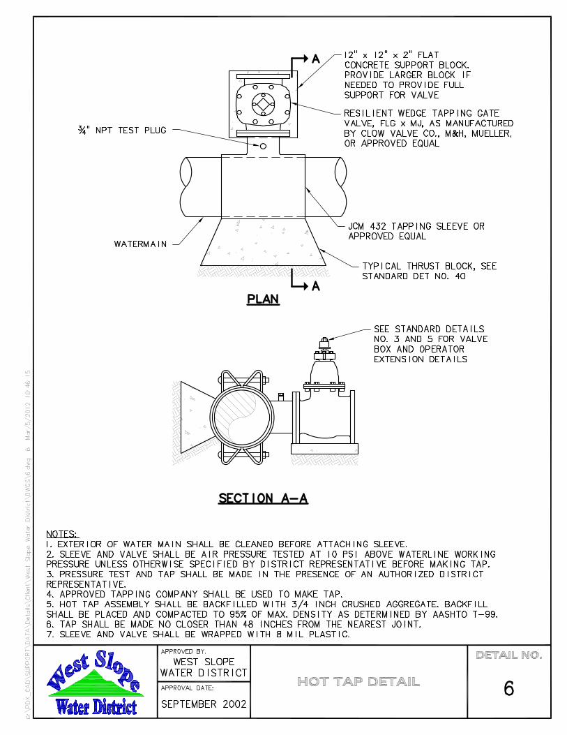


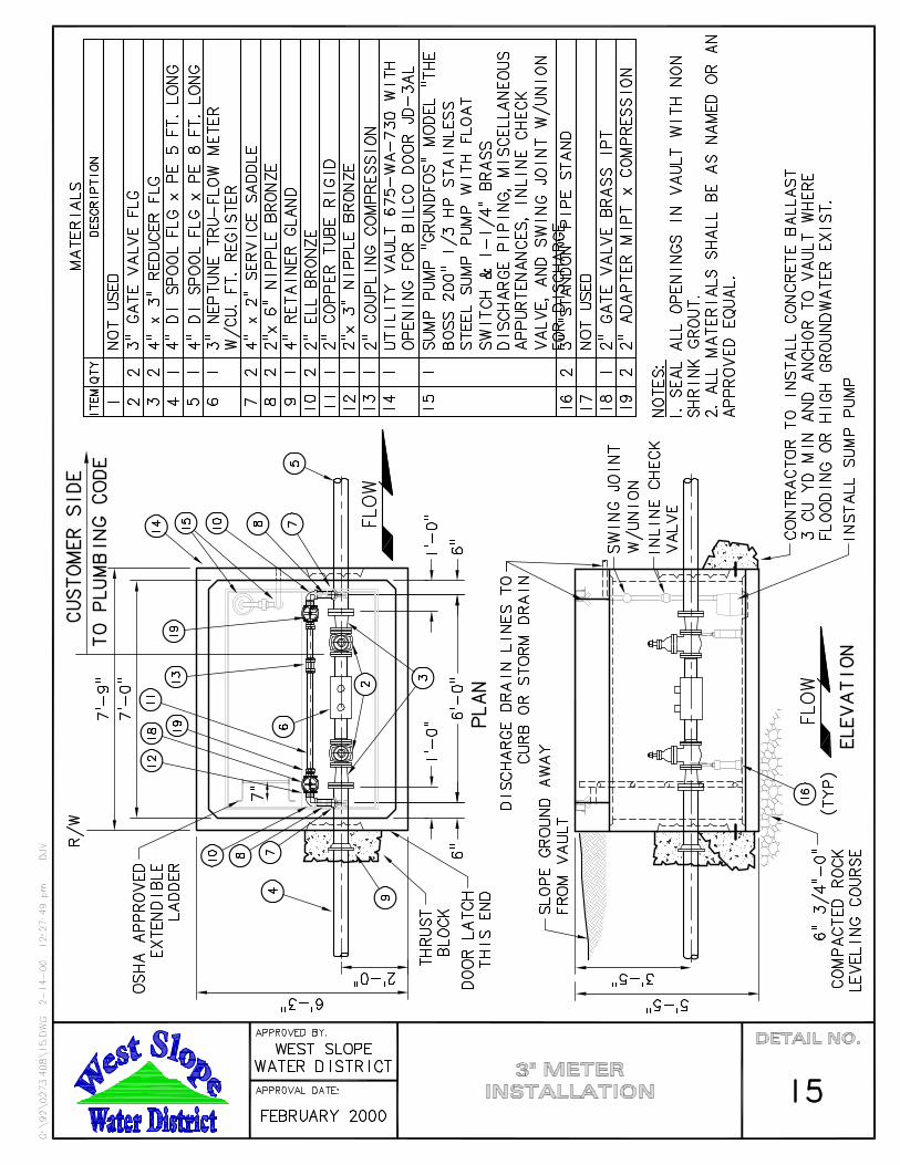

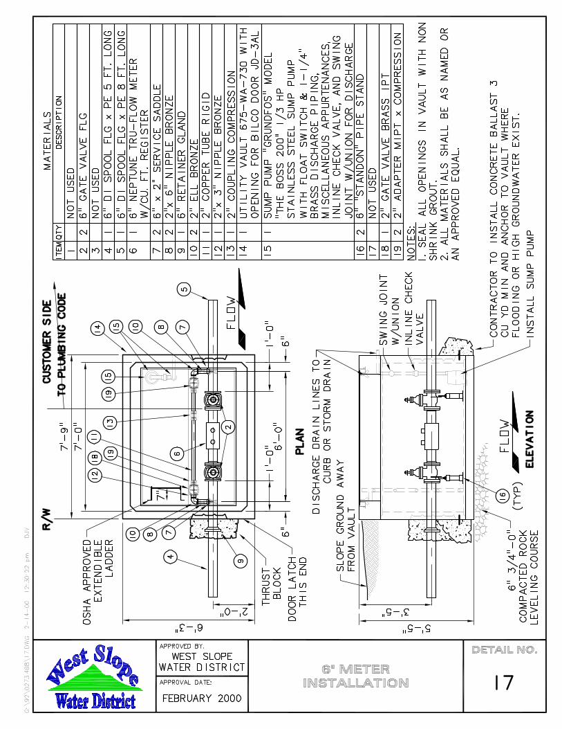


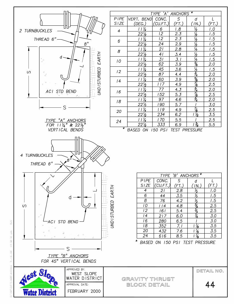


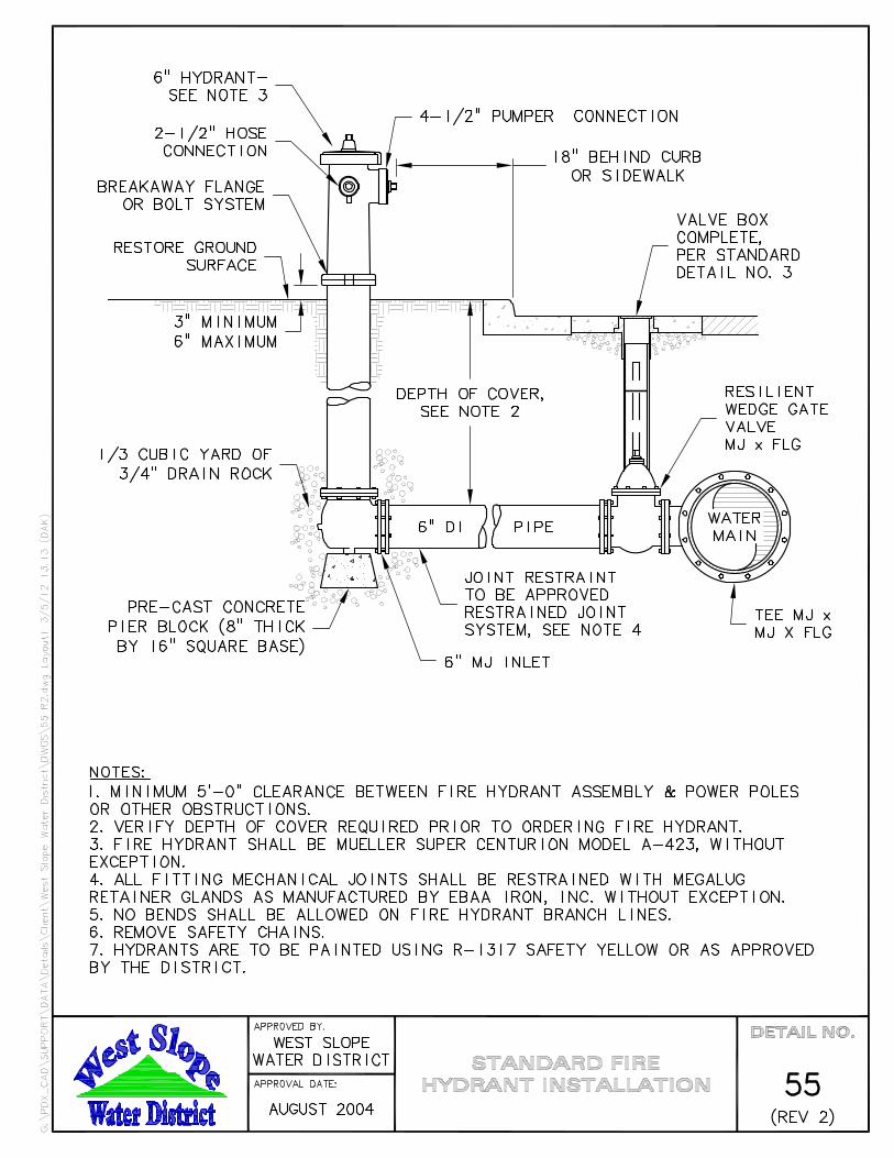
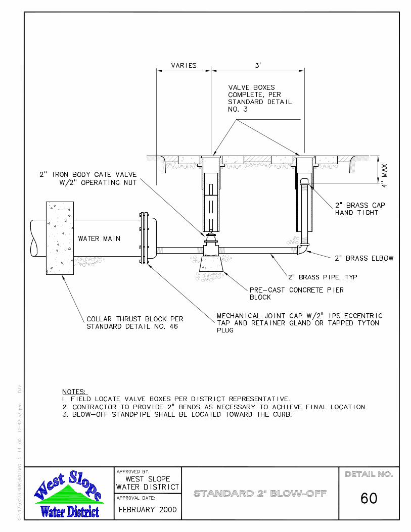
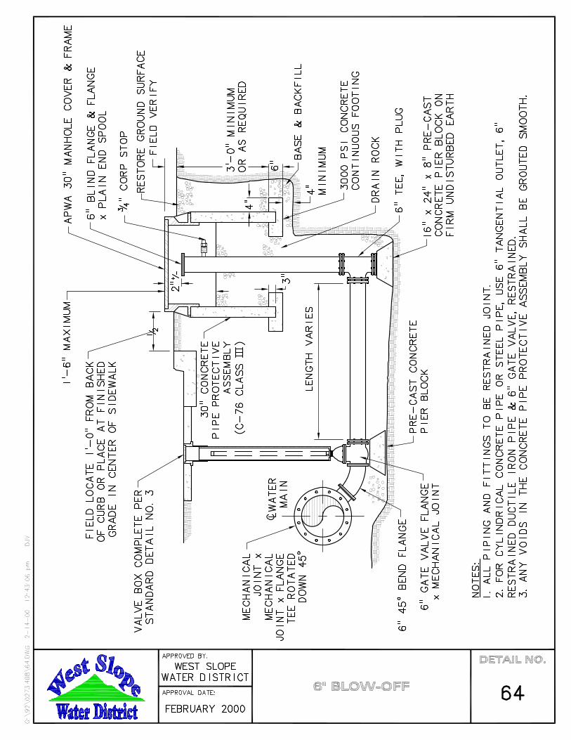

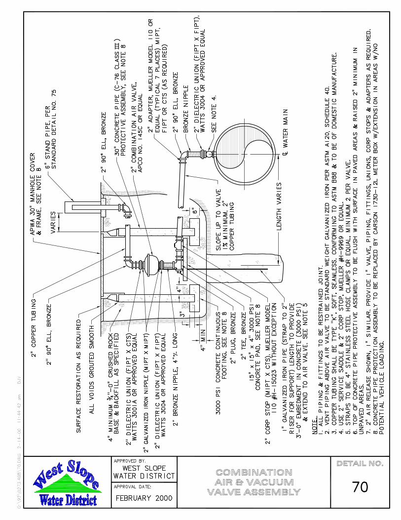

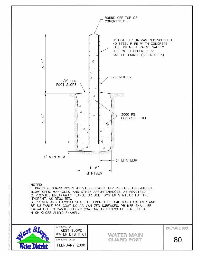


APPENDIX

RECEIPT, RELEASE AND WAIVER
To: WEST SLOPE WATER DISTRICT (WSWD) Contract: Owner’s Project No.: Contract Date:
KNOW ALL PERSONS BY THESE PRESENTS: The undersigned acknowledges that receipt of $ to be paid to the undersigned by WEST SLOPE WATER DISTRICT, will constitute final payment, plus retainage, pursuant to the terms and conditions of the Contract referenced above, between the undersigned and WEST SLOPE WATER DISTRICT for labor and materials. The undersigned acknowledges the total cost of said Contract was $ , and that the undersigned was previously paid $ . In consideration of the final payment as set forth above, the undersigned with full intent and knowledge of the facts and circumstances and as a free and voluntary act and deed hereby releases, holds harmless, and indemnifies WEST SLOPE WATER DISTRICT, its officers, agents, and employees from, and waives its right to all claims, demands, actions and suits, including all attorney fees and costs, of every nature, that it may now or ever have against WEST SLOPE WATER DISTRICT, its officers, agents, and employees arising out of the Contract referenced above. The undersigned hereby certifies that all work required by the Contract referenced above is complete; and, that all amounts due for labor, materials and all other obligations under said Contract were paid by the undersigned; and, that all actions for injuries or damage arising out of operations and work required by said Contract were fully and finally settled or are fully covered by insurance protecting the undersigned, WEST SLOPE WATER DISTRICT, its officers, agents and employees and all other governmental bodies, their officers, agents and employees.
[Corporation Seal] Signature
Title
State of ) ) County of )
This instrument was acknowledged before me on
by (name) as
(title) of (company).
Notary Public for (State) My commission expires:

Right-of-Way Permit Application �������������� ����������������� �������������� ����������������������������������
���������������������� ����������������������
Permit Type: UTILITY
���������� ����������������������������������������� �������� ����� ����������������������������� !""����� #����������$����% ������������������&�##���$��'��() *+,-���.��%"+��/!0�)0*+�1�,234.�%"+�/!0�)0*",5� �#.��� 6�������7�89 �������8�8��
Work Site InformationAddress (if work is associated with a parcel):
Road Name: Limits or cross-streets:
City: Tax Map & Lot #:
Applicant � Responsible for Project (permittee) � Primary Contact Utility: Contact Name:
Mailing Address: 24-Hour Phone:
City / State / ZIP:
Office Phone: Cell Phone: Fax:
E-mail:
Contractor � Same as above � Responsible for Project (permittee) � Primary Contact Business Name: Contact Name:
Mailing Address: E-mail:
City / State / ZIP:
Office Phone: Cell Phone: Fax:
24 Hour Emergency Phone: License or CCB Number(s):
Proposed Start Date: Estimated Completion Date:
County Case File No.: Subdivision Name:
Applicant’s Project No.:
Type of Wor�New Facility Repair / Replace Existing Facility Bore Open Trench Plow
Approx. Size of Proposed Excavation: Length (ft) Width (ft) Depth (ft)
Approx. Length of Bore Line: (ft)
Description of Work (including location in the right-of-way):
� Check Here to Request Consideration for Use of Steel Plates in the Right-of-Way
Steel Plates shall not be used in the Right-of-Way without express written permission from Washington County
Applicant agrees to perform operations in rights-of-way under jurisdiction of Washington County, Oregon in accordance with the appropriate General Provisions contained in "Washington County, Department of Land Use and Transportation, Rules and Regulations for Pole Line, Buried Cable, Pipe Line, and Miscellaneous Operations and/or Facility Permits" as supplemented and modified by the Standard in effect and any Special Provisions shall apply to this permit, and by this reference, are made a part thereof. It shall be the obligation of the applicant to obtain said Standards and Rules and Regulations from the Department of Land Use and Transportation and to determine which of the various provisions are applicable before commencement of work under this permit. It shall be the applicant's responsibility to ensure compliance with Oregon Revised Statutes 209.140 and 209.150 including all subsections, with respect to interference, removal, or destruction of survey monuments.
Applicant Printed Name: Title:
Applicant Signature: Date:
'���")1 �
����������� �����Bore & Open Trench
�������������������������������������
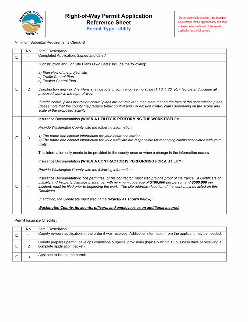
Minimum Submittal Requirements Checklist
No. Item / Description
� 1 Completed Application: ���������������
� 2
*Construction and / or Site Plans (Two Sets): Include the following:
�!�"����#� �� ��������$���������!�%�� ��&�������"�����!�'������&�������"�����&���������������(��������"��������������������� ������������������)*+*,-�*+.,-����!-������������������������������� ��/������������ � ������ ���� ����������������������������������������������������#���-������������������������ ����� �������������������������"����������������������������������������� ��������������(��������������������������������������������������������� �����������������#����
� 3
Insurance Documentation (WHEN A UTILITY IS PERFORMING THE WORK ITSELF):
"��#������������&������ ������� ���� ��� �������+��*!�%��������������������� �������� ������������������������.!�%��������������������� �������� ����������� � ������������������ ������������������������� ����������������This information only needs to be provided to the county once or when a change in the information occurs
� 4
Insurance Documentation (WHEN A CONTRACTOR IS PERFORMING FOR A UTILITY):
"��#������������&������ ������� ���� ��� �������+�
Insurance Documentation: %�����������-�����������������-��������������#������� �� ��������������&��� ������ �0����������"��������1��������������-� �����������#������ ��������������������������������������������-��������� ���������������������� ��/���%���������������(���������� ����� ��/����������������������&��� ����������������-�����&��� ������������������������ ������������ ���+���������������������������������������������� ����������������� ��������!�
Permit Issuance Checklist
No. Item / Description
� 1 County reviews application, in the order it was received. Additional information from the applicant may be needed.�
� 2County prepares permit, develops conditions & special provisions (typically within 10 business days of receiving a complete application packet).�
� 3 Applicant is issued the permit.
Right-of-Way Permit Application Reference Sheet Permit Type: Utility
����������������������:#���8��;����������6�6 ����<�������<������ ��#�� ����#�� �6�6��������6������� 6��� ���<������������ ��#�� ����������� #�� �:��8

121 S.W. Salmon, Suite 900 Portland, Oregon 97204-2919 www.msa-ep.com