Embed Size (px)
Citation preview

FELIX STORCH, INC.
Summit Appliance Division 770 Garrison Avenue
Bronx, New York 10474 www.summitappliance.com
WATER-LINE CONNECTION INSTRUCTIONS FOR INSTALLED (MODULAR) ICE MAKERS
Important Information
This manual gives you complete instructions on how to connect a water line to an ice maker already installed in your SUMMIT refrigerator. Please read the manual carefully and follow the instructions exactly as described. Make sure you observe all safety instructions.
A certain amount of mechanical ability is required to complete the water connection process.
You will have to purchase a copper tubing kit that contains a "Regular Valve and Clamp Assembly" (for refrigerators with an automatic ice maker, or self-filling trays). The kit contains all of the hardware necessary to connect your ice maker to the water supply. You can purchase one at most hardware or plumbing supply stores.
DO NOT USE PIERCING-TYPE OR 3/16" SHUT-OFF VALVES. They reduce the flow of water to the ice maker and are easily clogged.
DO NOT USE POLYETHYLENE TUBING to connect the ice maker to the water line. Use only 1/4" (O.D.) copper tubing.
CUSTOMER INSTALLATION IS NOT WARRANTED BY THE REFRIGERATOR OR ICE MAKER MANUFACTURER.

1
Installing the Water Line
Choosing a location 1. Open the copper tubing kit that you purchased previously, and lay the
contents neatly on a table where you can identify them easily. The parts from the kit that you will use are as follows:
1 Regular valve (not the steel-piercing type) 2 Compression sleeves 2 Compression nuts 2 Clamps 2 Screws 2 Nuts 1 Gasket seal * 1 Length of coiled copper tubing *- Not needed for 11FTA models (24ECKMF kit)
NOTE: When you work with the soft copper tubing, be careful not to kink it. If you accidentally kink the tubing, do not use it. IMPORTANT: Do not install water line tubing in a location where the temperature may fall below freezing; otherwise, property damage could occur. 2. Choose a suitable water pipe
location to install the water shut-off valve (see diagram at side for some suggested locations). We recommend installing the valve on a vertical length of cold (not hot) water pipe that is nearest your refrigerator. If a vertical length of pipe is not nearby, you can use a horizontal length of water pipe; however, you will have to drill the access hole for the valve into the top or side of the pipe (not the bottom). This will keep water in the pipe from flowing down onto the drill, and also keep sediment from collecting in the valve later. NOTE: Depending on the location of the horizontal pipe in relation to the floor and wall, drilling into it may not be possible.
3. Drill a ⅜" hole through the floor or wall to the water pipe.

2
Routing the copper tubing Refer to the diagram on the side for the following steps. 1. Uncoil the necessary length of
copper tubing and straighten it, then route the end of the tubing through the access hole you drilled to the location you have chosen to install the shut-off valve. Straighten only enough of the copper tubing to reach this location. Leave the rest coiled near the access hole.
2. At this time, make sure that you have been supplied with enough tubing so that when you are finished connecting the water line, you will have enough coiled behind the refrigerator to easily move it forward far enough to clean behind it. Also make sure that the coils are large enough so that when the unit is pulled forward, the winding will not stretch too far and kink.
5. Use a hammer and a center punch, and mark the location of the hole for the shut-off valve. If you are marking copper tubing, do not strike the punch hard enough to bend it.
6. Install a ¼" bit in the drill, and carefully drill an access hole through just the front side (not through both sides) of the cold water pipe.
3. Turn off the cold water supply going to the water pipe where you will be installing the shut-off valve.
7. Check the hole and make sure that you have drilled completely through one side of the pipe. The edges of the hole should be smooth and round. If necessary, use a small ¾-round file to remove any rough edges from inside the hole, and any burrs from around the top of the hole.
4. Open a cold water tap that is connected to the selected water pipe and bleed off the water pressure. Leave the tap open until after you complete the water line hook up.
3
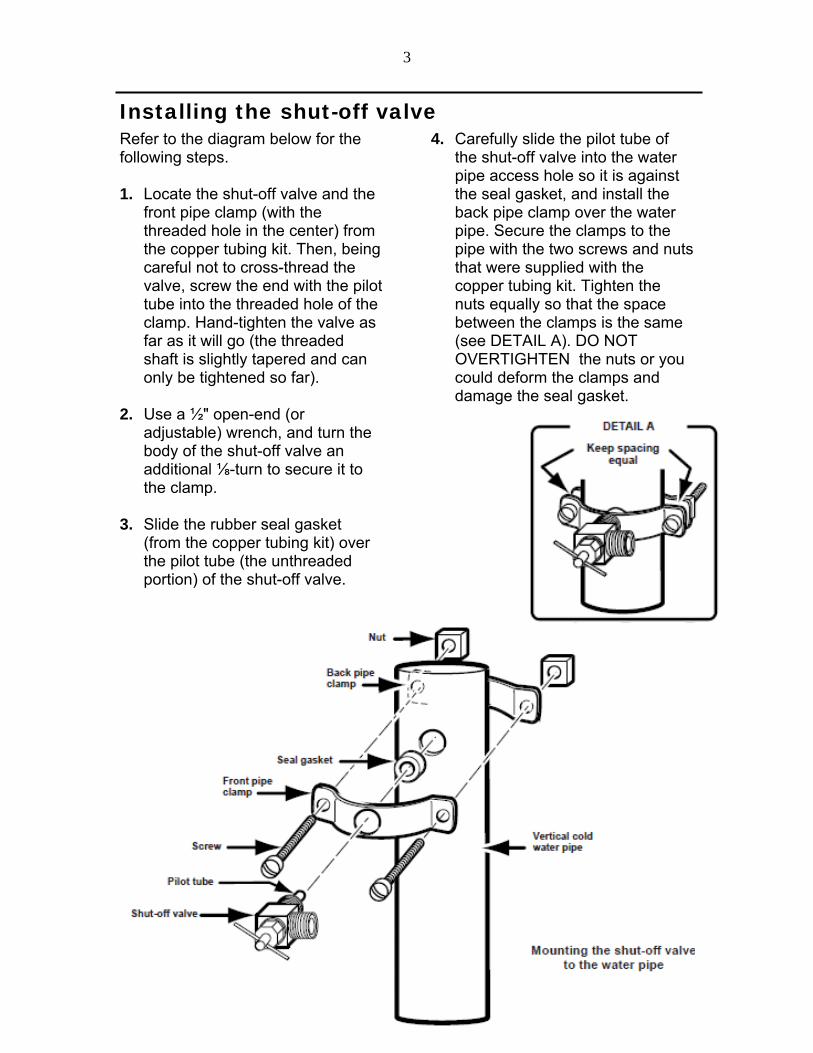
Installing the shut-off valve Refer to the diagram below for the following steps. 1. Locate the shut-off valve and the
front pipe clamp (with the threaded hole in the center) from the copper tubing kit. Then, being careful not to cross-thread the valve, screw the end with the pilot tube into the threaded hole of the clamp. Hand-tighten the valve as far as it will go (the threaded shaft is slightly tapered and can only be tightened so far).
2. Use a ½" open-end (or adjustable) wrench, and turn the body of the shut-off valve an additional ⅛-turn to secure it to the clamp.
3. Slide the rubber seal gasket (from the copper tubing kit) over the pilot tube (the unthreaded portion) of the shut-off valve.
4. Carefully slide the pilot tube of the shut-off valve into the water pipe access hole so it is against the seal gasket, and install the back pipe clamp over the water pipe. Secure the clamps to the pipe with the two screws and nuts that were supplied with the copper tubing kit. Tighten the nuts equally so that the space between the clamps is the same (see DETAIL A). DO NOT OVERTIGHTEN the nuts or you could deform the clamps and damage the seal gasket.

4
Connecting the copper tubing to the shut-off valve Refer to the diagram below for the following steps. 1. Straighten a 2" section of copper
tubing and make sure that the opening is round and cut evenly across the end. If necessary, use a tubing cutter (or a hacksaw) and cut the end off, then file it so it is even, and remove any burrs from around the inside and outside edges so it is smooth and round. When you are finished, clean the filings from inside the tubing as much as possible.
2. Position the compression nut as shown, and slide it over the end of the copper tubing.
3. Slide a compression sleeve over the copper tubing until it is approximately 1" from the end.
4. Insert the end of the copper tubing into the outlet connector of the shut-off valve as far as it will go, and then hand tighten the compression nut as much as possible.
5. Using a ½" open-end wrench, further tighten the compression nut on the shut-off valve one additional turn. If necessary, you will tighten the nut further after you turn on the water supply.
6. Turn the T-handle on the shut-off valve to its fully "open" (counterclockwise rotation) position.

5
Connecting the copper tubing to the water valve Refer to the diagram below for the following steps. 1. Check to make sure that the free
end of the tubing is round and cut even. If necessary, prepare the end in the same manner as you did earlier. Be sure to clean the filings from inside the tubing after you prepare the end.
When you perform the next step, be careful not to kink the copper tubing. 2. Starting at the free end,
straighten approximately 20" of the copper tubing.
3. Close the water tap you left open earlier to bleed the water lines.
4. Insert the end of the copper tubing into a pail, and have someone turn on the water supply. Allow enough water to flow through the lines to thoroughly flush them out. Once the water runs clear, turn off the supply and bleed the lines.
5. Remove the strain relief clamp from the rear of the cabinet and slide it over the end of the copper tubing. Make sure you position the flanges as shown.
6. Slide a compression nut over the free end of the copper tubing.
7. Slide a compression sleeve over the copper tubing and position it 1" from the end.
8. If one is installed, remove the plastic cap from the water inlet fitting on the water valve and discard the cap.
9. Insert the end of the tubing into the water inlet connector at the top of the water valve as far as it will go, and hand tighten the compression nut as much as possible.
10. Use a ½" open-end wrench, and further tighten the compression nut on the water inlet connector one additional turn. If necessary, you will tighten the nut further after you turn on the water supply.
11. Mount the strain relief clamp to the back of the cabinet with the hex-head screw you removed earlier.
6
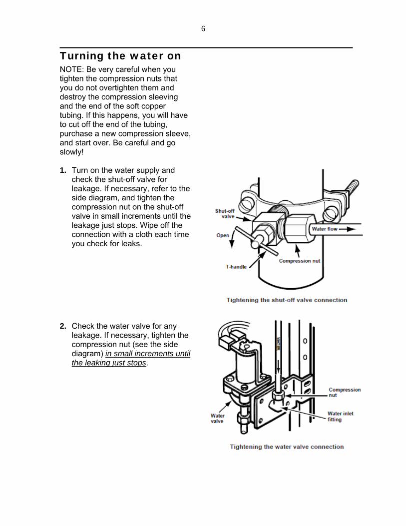
Turning the water on NOTE: Be very careful when you tighten the compression nuts that you do not overtighten them and destroy the compression sleeving and the end of the soft copper tubing. If this happens, you will have to cut off the end of the tubing, purchase a new compression sleeve, and start over. Be careful and go slowly! 1. Turn on the water supply and
check the shut-off valve for leakage. If necessary, refer to the side diagram, and tighten the compression nut on the shut-off valve in small increments until the leakage just stops. Wipe off the connection with a cloth each time you check for leaks.
2. Check the water valve for any leakage. If necessary, tighten the compression nut (see the side diagram) in small increments until the leaking just stops.

7
Final Installation
Forming the copper tubing Loop the copper tubing coming from the water valve as shown. Position the coiled copper tubing near the center of the unit so that it forms an "accordion-fold" (as shown in the diagram below) when it is moved to-and-from the wall.

8
Connecting the power/Leveling the unit 1. Plug the power cord into its AC
outlet, and carefully push the refrigerator back against the wall
2. Place a level on top of the cabinet. If you need to re-level the refrigerator, follow the procedure to adjust the front casters, as outlined in your refrigerator's Use and Care Guide.
3. Check the position of the ice maker. If it is crooked and needs to be adjusted, loosen the bottom bracket screws (see the side diagram) and position the unit as desired, then tighten the bracket screws.
9
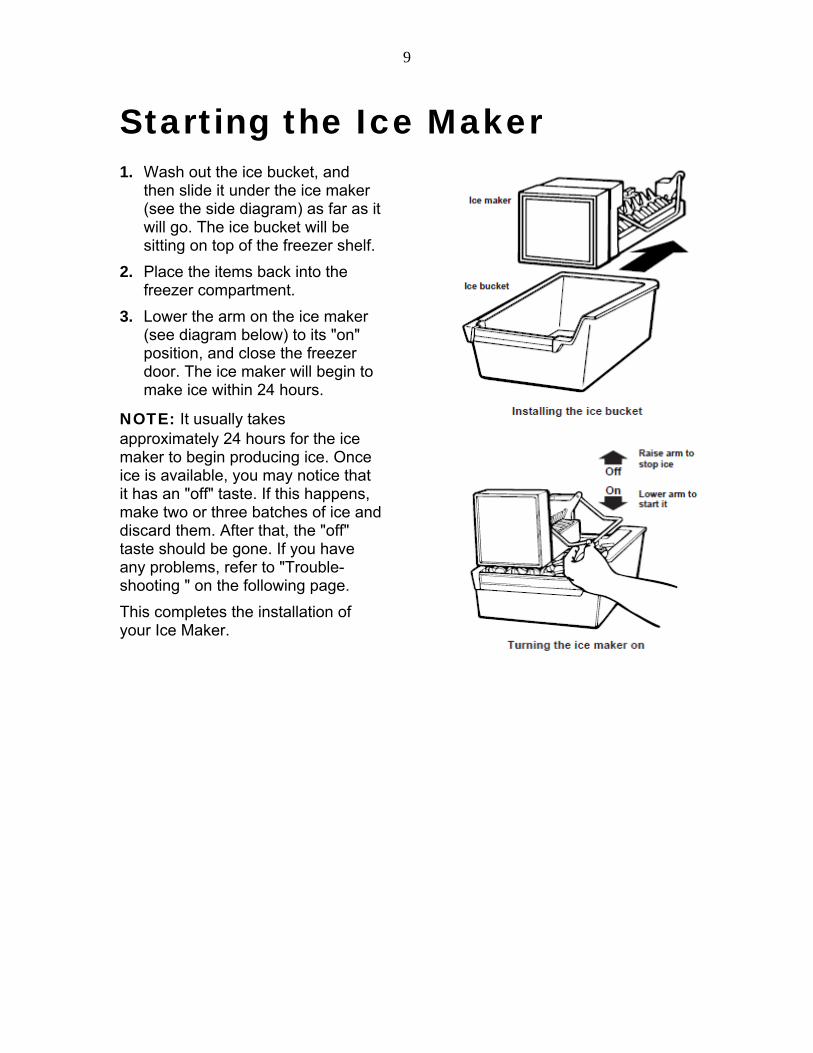
Starting the Ice Maker 1. Wash out the ice bucket, and
then slide it under the ice maker (see the side diagram) as far as it will go. The ice bucket will be sitting on top of the freezer shelf.
2. Place the items back into the freezer compartment.
3. Lower the arm on the ice maker (see diagram below) to its "on" position, and close the freezer door. The ice maker will begin to make ice within 24 hours.
NOTE: It usually takes approximately 24 hours for the ice maker to begin producing ice. Once ice is available, you may notice that it has an "off" taste. If this happens, make two or three batches of ice and discard them. After that, the "off" taste should be gone. If you have any problems, refer to "Trouble-shooting " on the following page.
This completes the installation of your Ice Maker.

10
Troubleshooting Operational notes 1. The Ice Maker water valve
contains a flow washer that acts like a pressure regulator to control the water flow. For the Ice maker to work properly, the water pressure in your home must be between 20 and 120 pounds-per-square-inch (psi). If you encounter problems with your Ice Maker's ability to product ice, call your water utility company and have the water pressure checked.
2. The Ice Maker's water valve is equipped with two strainers: a plastic basket type and a wire-mesh screen. Both of these can be cleaned by turning off the water and disassembling the water valve (your service center should be able to provide this service). If local water conditions require periodic cleaning, or if you use a well as a water source, you should consider installing a second water strainer in the water line. You can obtain a water strainer from your local appliance dealer.
Troubleshooting chart The following chart lists several common problems that could occur with your Ice Maker. PROBLEM CAUSE One or more of the following sounds is heard:
Buzzing Trickling water Thud (clatter of ice)
The water valve is operating. Water is entering the Ice Maker to fill cup. Ice is being dumped into the ice bin.
Ice tastes stale. The ice is old. Make a new batch. Water in Ice Maker overflows. Refrigerator or Ice Maker is not level. If the Ice
Maker still overflows after leveling, turn off the Ice Maker's water supply at the shut-off valve, and raise the Ice Maker's bail arm to the "off" position (see previous page); then contact your local service center.
Not enough ice. It will take 48 hours to fill the ice bucket. The ice maker will make ice every 2 to 3 hours. For more ice, adjust the freezer control to a colder setting.
Ice making has stopped. Be sure that the bail arm is lowered into the ice bucket (see previous page). Make sure that the water shut-off valve is open. The water shut-off valve or the water valve screen is clogged. (Contact your local service center.)
11
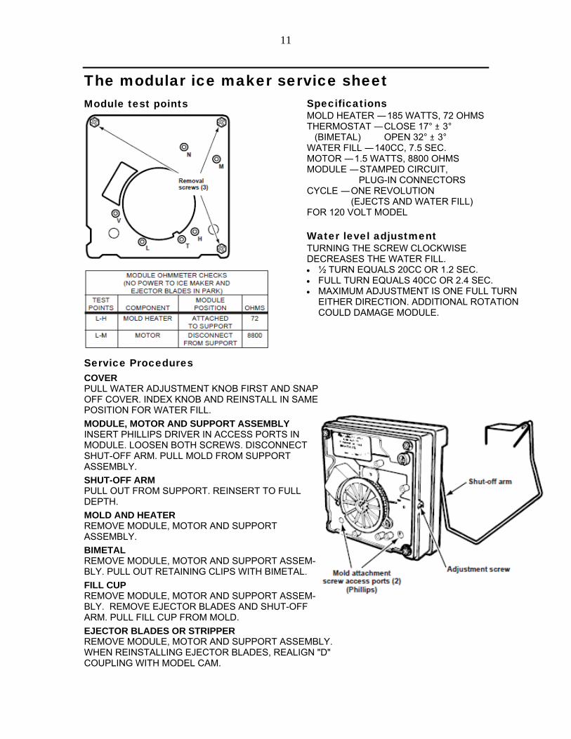
The modular ice maker service sheet Specifications MOLD HEATER — 185 WATTS, 72 OHMS THERMOSTAT — CLOSE 17° ± 3° (BIMETAL) OPEN 32° ± 3° WATER FILL — 140CC, 7.5 SEC. MOTOR — 1.5 WATTS, 8800 OHMS MODULE — STAMPED CIRCUIT, PLUG-IN CONNECTORS CYCLE — ONE REVOLUTION (EJECTS AND WATER FILL) FOR 120 VOLT MODEL
Water level adjustment TURNING THE SCREW CLOCKWISE DECREASES THE WATER FILL. ½ TURN EQUALS 20CC OR 1.2 SEC. FULL TURN EQUALS 40CC OR 2.4 SEC. MAXIMUM ADJUSTMENT IS ONE FULL TURN
EITHER DIRECTION. ADDITIONAL ROTATION COULD DAMAGE MODULE.
Module test points Service Procedures COVER PULL WATER ADJUSTMENT KNOB FIRST AND SNAP OFF COVER. INDEX KNOB AND REINSTALL IN SAME POSITION FOR WATER FILL.
MODULE, MOTOR AND SUPPORT ASSEMBLY INSERT PHILLIPS DRIVER IN ACCESS PORTS IN MODULE. LOOSEN BOTH SCREWS. DISCONNECT SHUT-OFF ARM. PULL MOLD FROM SUPPORT ASSEMBLY.
SHUT-OFF ARM PULL OUT FROM SUPPORT. REINSERT TO FULL DEPTH.
MOLD AND HEATER REMOVE MODULE, MOTOR AND SUPPORT ASSEMBLY.
BIMETAL REMOVE MODULE, MOTOR AND SUPPORT ASSEM- BLY. PULL OUT RETAINING CLIPS WITH BIMETAL.
FILL CUP REMOVE MODULE, MOTOR AND SUPPORT ASSEM- BLY. REMOVE EJECTOR BLADES AND SHUT-OFF ARM. PULL FILL CUP FROM MOLD.
EJECTOR BLADES OR STRIPPER REMOVE MODULE, MOTOR AND SUPPORT ASSEMBLY. WHEN REINSTALLING EJECTOR BLADES, REALIGN "D" COUPLING WITH MODEL CAM.

12

13
FELIX STORCH, INC. 770 Garrison Avenue Bronx, NY 10474 Phone: (718) 893-3900 Fax: (718) 842-3093 www.summitappliance.com
For parts and accessory ordering,
troubleshooting and helpful hints, visit:
www.summitappliance.com/support or call Customer Service toll-free
at (800)-932-4267