Embed Size (px)
Citation preview

1
1) Student of Universitas Maritim Raja Ali Haji
2) Lecture of Universitas Maritim Raja Ali Haji
WATER LEVEL CONTROL SYSTEM OF TILAPIA PONDS USING
ARDUINO-BASED ULTRASONIC DISTANCE SENSOR
Zul Asfiansyah1)
, Rozeff Pramana,S.T, M.T 2)
, Deny Nusyirwan, M.Sc 2)
-Abstract-
Rapid technological developments have an impact on all aspects of the field of work so a
lot of the application of science and technology that is designed to simplify the job. One is the
content fill process and drain the water in the pond tilapia farm that aims to keep the water level
to suit the needs of the fish. Water level control system of tilapia ponds designed to facilitate
farmers in maintaining high water on the pond tilapia with control using the Personal Computer.
The system is designed using the Arduino as a control center that will control the relay to turn on
the tap electric and water engines. Proximity sensor that is used to monitor the water level is an
ultrasonic distance sensor PING. PING will provide feedback on the value of Arduino that will
determine the output of the system to be run by either the process of filling or draining the pond
water. By using a water machine and 4 pieces of tap electric, drains can be designed that is able
to fill the water and drain the water mechanically. Interface to the system would make it easier to
use. There are two control modes that can be used, the AUTO mode to select the type of tilapia
pond that will be used and MANUAL mode by pressing the ISI or KURAS to run the system.
Key Word : Control, Arduino, Tilapia, PING
INTRODUCTION
Background
Rapid technological developments lately
impact on all aspects of the field of work,
almost all of the work done by human labor
has been done in order to research how the
job can be done better controlled by using
control techniques that apply the knowledge
of electrical and mechanical concepts.
One of the jobs in Indonesia today are
still using the traditional way, namely in the
field of fish farming in the filling and
draining water fish pond. We will make the
filling water into the pond, the farmer should
open the valve that connects into the pool
and headed to the water machine located far
apart and the engine usually located close to
the water source. Then when the pool fills
with water, the farmer should pay attention
to the height of the pool water in accordance
with the needs of the fish, so the farmers
have to go back to the pool and estimate
whether water-filled pond is enough or not,
even some that use a wooden stick to
determine the height of the pool water .
Having adequate water, the farmer should
back off the engine and back water valve
closes.
Tilapia is a freshwater fish consumption
by fish body shape is elongated and white-
black. In tilapia fish farming, the water level
must be considered in order to keep the
condition of the fish and the water quality is
good. Well when fish during spawning, fish
spawning or during growth.
Problem Formulation
Based on the above background, it can
be formulated-constraint problems exist:

2
Engineering Faculty
Universitas Maritim Raja Ali Haji
a. How to design a control system of filling
and draining pool water that is able to
work for 24 hours?
b. How to design a system that can fill and
drain the pool water without the use of
human labor?
c. By applying the concept of
electromechanical, a case of what the
water level can be used in a tilapia fish
farm ponds?
Limitations
a. This system does not impose limits on the
duration when filling or draining pool
water.
b. The system is applied to one type of pool
in a smaller scale (prototype).
c. Water used machine is the water machine
type MRC -100N 350W.
d. Valve used is electric valve 220V AC 1/2
inch
e. The microcontroller used in this system is
the Arduino MEGA 2560.
Destination
The purpose of the design of this system are:
a. The system can maintain water levels in
the pond certain conditions.
b. Draining and filling the pool water can be
controlled using a PC without using
manpower to manually turn on the water
machine, or also install pipes and unscrew
the valve the water flow into the pond.
LITERATURE REVIEW
Previous studies
There are several studies that have been
done previously associated with the design
of this system as research conducted by Eko
Syamsuddin, et al (2007) who designed a
water thermostat and automatic filling water
bath through a short message service-based
microcontroller. Water sensor used is a
resistive sensor that is placed at the lower
limit and upper limit of the water bath.
Output voltage of the sensor and a
microcontroller in if the resulting output
logic for the system.
Tegar Bakhti Prihantoro, et al (2010)
designed a water level detector
automatically on water reservoirs using
ultrasonic sensors based microcontroller.
Microcontroller used is ATMEGA8535
which controls automatic water machine
using relay. Ultrasonic sensors will provide
input to the microcontroller, and then turn
on the water until the machine is full of
water and the machine will stop
automatically.
I Made Budhi Dwipayana (2010) created
a simulation of the design water level PC-
based control system. Detection of water
level on the tool uses pulleys and float
construction has been designed with a sensor
optocoupler. The working principle is the
same sensor as the principle of the mouse
wheel work consisting of 2 and 1 infrared
phototransistor. 2 pieces of the
phototransistor will generate 2 pulses which
have a phase difference as an input into the
PC and processed using Delphi 7.0 software
to determine the output of the system is
started the water.
Harlinda. L (2010) designed a water
level control with visual basic programming,
which use water sensors utilize the
principles of transistor work as a switch that
will turn on the LED and received by the
microcontroller. The design of this sensor
utilizing the properties of water as a
conductor of electricity for the water sensor
driver. For a tank, water sensors installed 6
units with different height levels ranging
3
Engineering Faculty
Universitas Maritim Raja Ali Haji
from the lowest to the highest limit the water
tank.
Basis Theory
Closed Loop Control Systems
Closed-loop control system is a control
system in general which affect the work
output signal of the system itself. So the
closed-loop control system is composed of a
control section itself, and also plant
controlled sensors as feedback to be
received by the control section. (Katsuhiko
Ogata: 2002)
Image 2.1 Closed Loop Control System
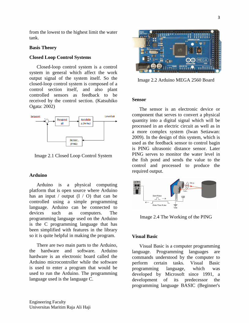
Arduino
Arduino is a physical computing
platform that is open source where Arduino
has an input / output (I / O) that can be
controlled using a simple programming
language. Arduino can be connected to
devices such as computers. The
programming language used on the Arduino
is the C programming language that has
been simplified with features in the library
so it is quite helpful in making the program.
There are two main parts to the Arduino,
the hardware and software. Arduino
hardware is an electronic board called the
Arduino microcontroller while the software
is used to enter a program that would be
used to run the Arduino. The programming
language used is the language C.
Image 2.2 Arduino MEGA 2560 Board
Sensor
The sensor is an electronic device or
component that serves to convert a physical
quantity into a digital signal which will be
processed in an electric circuit as well as in
a more complex system (Iwan Setiawan:
2009). In the design of this system, which is
used as the feedback sensor to control bagin
is PING ultrasonic distance sensor. Later
PING serves to monitor the water level in
the fish pond and sends the value to the
control and processed to produce the
required output.
Image 2.4 The Working of the PING
Visual Basic
Visual Basic is a computer programming
language. Programming languages are
commands understood by the computer to
perform certain tasks. Visual Basic
programming language, which was
developed by Microsoft since 1991, a
development of its predecessor the
programming language BASIC (Beginner's

4
Engineering Faculty
Universitas Maritim Raja Ali Haji
All-purpose Symbolic Instruction Code) was
developed in the 1950s. Visual Basic is one
of the Development Tool is a tool for
making a wide variety of computer
programs, especially those that use the
Windows operating system. Visual Basic is
a computer programming language that
supports object (Object Oriented
Programming = OOP). (Krishna D.
Octovhiana: 2003)
Tilapia
Based on research conducted by the
National Development Planning Agency
(2000), for raising tilapia we should pay
attention to the pool to be used, because
each fish has a way of life different. There
are 4 types of pools needed to raise tilapia,
which is an aircraft maintenance / spawning
pool, pool maintenance seed / nursery
ponds, and rearing ponds. Any use of the
pool, the pool must pass through stages of
preparation in which to prepare the pool, the
water level must be maintained within a few
days to get the pool water with a good
mineral content required by tilapia.
Table 2.1 Water height pool Tilapia
Level Air
Minimum Maksimum
Spawning
pool 40 cm 60 cm
Separating
pool 30 cm 50 cm
Growth pool 75 cm 100 cm
harvest 7 cm 12 cm
Preparation
growth pool 5 cm 10 cm
RESEARCH METHODOLOGY
System Overview
On water level control system of tilapia
pond is built using several components, such
as PING ultrasonic distance sensor is used to
determine the height of the water, which is
used to electrically tap unscrew the valve,
the relay is used to turn on and turn off the
water motors and an Arduino as a control
center this system.
Image 3.1 Altitude Control System Block
Diagram Water Pond
Part of the controller will receive input
from the sensor, the sensor values will be
compared with a set point that we created
earlier. The comparisons that determine
whether the output of the system will make
the filling water into the pond or whether the
system should do the drainage pond. Then
the two processes lead to changes in the
water level in the pond and the sensor will
send a signal to the controller values that
will make the process of returning.
The filling and draining system the pool
water
At the time of filling and draining the
pool water, this system will work drain the
water from the source to the pool and from
the pool to drain. In this system is designed
so that the process can be controlled via the
PC enough to unscrew the valves that
connect all pools. Valves used are
electrically tap that has been designed to be
5
Engineering Faculty
Universitas Maritim Raja Ali Haji
controlled by the Arduino using the relay as
a switch. Electric valve works for a 220Vac
supply, the valve will open if given voltage
220VAC and will be closed if there is no
voltage. Then the pipes are connected to a
water machine water machine which works
based on a series of relays which are also
controlled by the Arduino.
Image 3.2 Electric Valve
Power Supply
To run this system of power needed for
the system to work. Power needed to supply
include:
• Arduino : 12V DC
• Relays : 12V DC
• Water Machine : 220V AC
• Taps Electric : 220V AC
To supply Arduino and relay, use a
power supply that is available in the market
with the output voltage of 24V DC, then to
the power supply voltage of 12V DC
required LM7812 regulator circuit so that
the output of the power supply can be used.
Image 3.3 Regulator 12V DC Circuit
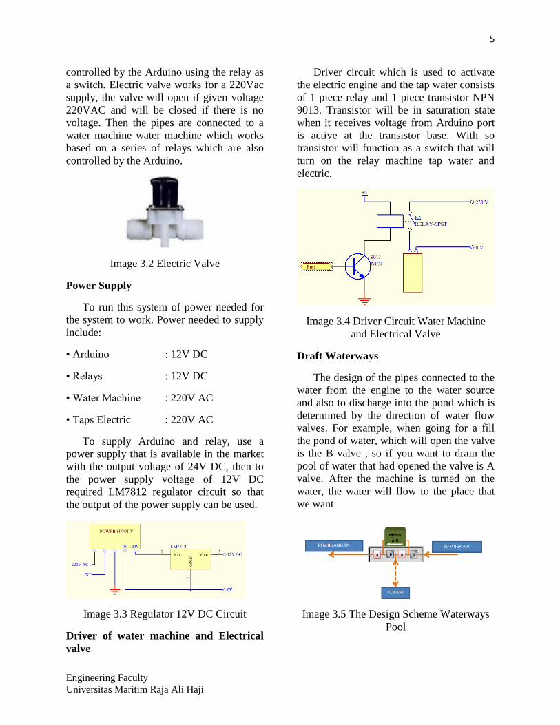
Driver of water machine and Electrical
valve
Driver circuit which is used to activate
the electric engine and the tap water consists
of 1 piece relay and 1 piece transistor NPN
9013. Transistor will be in saturation state
when it receives voltage from Arduino port
is active at the transistor base. With so
transistor will function as a switch that will
turn on the relay machine tap water and
electric.
Image 3.4 Driver Circuit Water Machine
and Electrical Valve
Draft Waterways
The design of the pipes connected to the
water from the engine to the water source
and also to discharge into the pond which is
determined by the direction of water flow
valves. For example, when going for a fill
the pond of water, which will open the valve
is the B valve , so if you want to drain the
pool of water that had opened the valve is A
valve. After the machine is turned on the
water, the water will flow to the place that
we want
Image 3.5 The Design Scheme Waterways
Pool

6
Engineering Faculty
Universitas Maritim Raja Ali Haji
Monitoring System of highest the pool
water
The system is designed to monitor the
condition of the pool water level. This
system serves to provide data on a set point
that will determine the output of the filling
system and drainage. In the design of this
system, which serves as a monitor is PING
proximity sensor which is designed with a
float as the object of observation. PING will
send the value of the distance through port 7
on the Arduino, then the value will be in the
process to determine the output of the
system.
Image 3.6 Water Elevation Monitoring
Scheme Design Pool
Interface Controller
In the design of this system, an interface
is needed to facilitate the running of the
system with a more attractive appearance on
the computer screen as a monitoring and
control system works. Manufacturing
interface for the water level control system
is an application using Visual Basic 6.
Controller interface is divided into two tabs,
the tab Auto and Manual.
Image 3.7 Interface Control System Altitude
Tilapia’s Pond
On the AUTO tab, the system will run as
a kind of pool we choose. Once the type of
pool is selected, the display will go out the
maximum and minimum bounds description
of the pool and the pool water level Actual
conditions. The system will start to work
after pressing the OK button. Pond water
level will adjust automatically according to
the type of pool you choose.
The system can also be used with
manual on MANUAL tab, given the
freedom to the user to either fill the water to
the pond without limitation, as well as for
the total depletion of the pool. The "ISI" to
start the filling process water pond, the
"KURAS" to the process of draining the
pool water and the "STOP" to stop the
ongoing process and display the water level
display indicates the actual condition of the
water level in the pond.
TESTING AND RESULTS
Testing The Circuit of Power Supply
Power supply used is a commercially
available power supply with output voltage
is 24V DC. while the required voltage is
12V DC, then use the circuit with 1 piece
LM7812 regulator to get the voltage to be
12V DC supply to the Arduino.

7
Engineering Faculty
Universitas Maritim Raja Ali Haji
Based on results of measurements that
have been performed on the output of the
regulator, the test results obtained as
follows.
Table 4.1 Regulator circuit Testing Results
Parameter Measurement Results
Input Voltage 24V DC
Output Voltage 12.2V DC
Arduino testing
Arduino that will be used should be
checked first on his pins, both the pin to be
used as input or output.
Testing Digital Output
In this research, the digital output pins
are used there are 3 pin. There are two
testing conditions on Arduino digital output,
which is the condition of LOW and HIGH.
Image 4.1 Arduino Digital Output Pin
Testing At LOW Conditions
Based on results of measurements that
have been performed on the third pin in the
LOW condition, the value obtained
following results
Table 4.2 Testing results of Pin Digital
Output LOW Conditions
Digital
Pin
Voltage
Measurement(VDC)
Condition
11 -0.01 LOW
12 -0.01 LOW
13 -0.01 LOW
Image 4.2 Arduino Digital Output Pin
Testing At HIGH Conditions
Based on results of measurements that
have been performed on the third pin in the
HIGH condition, the value obtained
following results
Table 4.3 Testing results of Pin Digital
Output HIGH Conditions
Digital
Pin
Voltage
Measurement (VDC)
Condition
11 4.77 HIGH
12 4.77 HIGH
13 4.77 HIGH

8
Engineering Faculty
Universitas Maritim Raja Ali Haji
Testing the Analog Input
To perform the test on the analog input,
the ADC can use already available on the
Arduino. Pin used is pin A0. On the A0 pin
and the voltage will be processed into the
Arduino as an analog signal, and then
converted into a digital signal using the
ADC and the results are displayed on the
monitor.
Based on the results of the testing that
has been done on the analog input pin, the
result of the display on the serial monitor as
follows.
Table 4.4 Analog Input Test Result
Tegangan Input Display On Monitor
5V 500
3.3V 343
0V 0
Serial Connection Testing with Visual
Basic
To perform the test using the program
input receiver in visual basic. Then the
readings are acceptable in the show at the
following layouts.
Image 4.3 Layout Testing Serial Monitor
Connection With Visual Basic
Based on the testing that has been done
with the Arduino to send data from Visual
Basic through a serial connection, obtained
the following results.
Table 4.5 Testing results for visual basic
serial connection
Input Voltage
(Volt)
Display On
Visual Basic
5 500
3.33 343
0 0
Relay Control circuit testing
Relay works when conditions transistor
9013 serves as a switch when in a state of
saturation with the receiving voltage from
Arduino pin. LOW when pin in conditions
where the transistor back in a normal state
so that the relay is inactive. But when
conditions changed to HIGH, the transistor
will be in saturation so that the relay will be
active.
Image 4.4 In the Active and Off Relay
testing circuit
Based on the tests performed on the
circuit using a relay with a multimeter,
showed the following results.

9
Engineering Faculty
Universitas Maritim Raja Ali Haji
Table 4.6 Relay Circuit Testing Results
Relay Digital
Pin
Condition Relay
Status
Relay of
Filling
valve
13 HIGH On
LOW Off
Relay of
Draining
valve
12 HIGH On
LOW Off
Relay of
Machine
11 HIGH On
LOW Off
Testing Electric Valve
In this research, electric valve is the
main device that determines the direction of
water flow. So that damage or problems that
occur in electrical tap will greatly affect the
overall system so that the system can’t fill or
drain the pond water. To ensure electrical
tap to work well, tested at the tap water that
has flowed to the supply voltage is 220V
AC.
Image 4.5 Testing the Electric Valve
Based on tests performed on an electric
valve with giving a supply voltages 188V
AC, Showed the following results
Table 4.7 Electric Valve Testing Results
Electric
Valve
Source
Voltage
Condition
Valve 1 188V AC Open Valve
0V Close Valve
Valve 2 188V AC Open Valve
0V Close Valve
Valve 3 188V AC Open Valve
0V Close Valve
Valve 4 188V AC Open Valve
0V Close Valve
PING testing Proximity Sensor
Proximity sensor PING testing done by
using tools such as a ruler and the object to
be detected.
Image 4.6 Distance Measurement Using
PING
Image 4.7 Results Rating Distance Decision
On Serial Monitor

10
Engineering Faculty
Universitas Maritim Raja Ali Haji
Based on tests performed by using PING
as distance sensors, measurement results
obtained distances displayed on the serial
monitor as follows.
Table 4.8 PING Distance Sensor Testing
Results
The Real
Distance (cm)
In the Serial Monitor
display distance
30 30
20 20
10 10
5 5
Through the Interface Control System
Testing
Control via the interface which has been
designed using Visual Basic form input
value fish pond water levels and also display
the actual water level was detected using the
proximity sensor PING
Image 4.8 Interface Controller System
At the interface consists of two tabs,
controlling tab which is lacking automatic
and manual control tab. At AUTO tab there
is a column type of an option to be used.
There are 5 types of pools to choose from
with different water levels vary, the
spawning pool, nursery, enlargement,
harvesting and pools that are currently in
preparation before use. When one type of
pools have been it will show the value of the
water level in the pond field maximum and
minimum limit on the interface. Then the
system will automatically direct to condition
the water level of the pond have been kind.
Display height of the water column is the
actual data of high-water pond using PING
taken every 1 sec.
In the manual control tab, users are
given the freedom to run the system.
Consists of three buttons, namely the "ISI",
"KURAS" and the "STOP". When the
button is pressed ISI, the system will
continue to fill water into the pool so if the
button is pressed KURAS system will drain
the pond. STOP button to stop the
functioning of the system that is running. To
find out how the height of the pool water,
the height of the column of water available
that show the actual height of tilapia pond
water. PING column is the distance between
the sensor with a float in the pool.
Image 4.9 Filling System Water Pool Is On
When Press the ISI Button

11
Engineering Faculty
Universitas Maritim Raja Ali Haji
Image 4.10 Draining System Water Pool Is
On When Press the KURAS Button
ANALYSIS AND DISCUSSION
Water level control system of tilapia
pond work using the PING ultrasonic
distance sensor measures the distance from
the PING function to float. Pond water
height values obtained by the distance to the
bottom of the pool by a PING minus PING
distance to the buoy. Values obtained water
level will be displayed on the Visual Basic
software via serial monitor. There are 5
types of pools, the spawning ponds with a
high range of 40 to 60 cm, with a range of
nursery ponds of 30 to 50 cm, an
enlargement of the range of 70 to 100 cm,
harvesting pond with a range of 7 to 12 cm
and the height of the water in the pool is in
preparations ranged from 5 to 10 cm.
Control system is done through the
interface that consists of two tabs control,
the tab control automatically which in this
tab users can simply select the type of pool
that will be used. PING determine the value
of the process to be run. If PING is greater
than the maximum limit of the pool, then the
system will perform as well if PING
depletion is smaller than the minimum
threshold, the system will make the filling
water into the pool. Control can also be done
manually. Interface available on the manual
tab consists of three buttons, the button
"ISI", "KURAS", and the "STOP". These
buttons function as the name implies.
CONCLUSIONS AND
RECOMMENDATIONS
Conclusion
Based on the obtained results, it can be
concluded that:
1. By utilizing Arduino as a controller
involving sensor to monitor the distance
the object and value feedback on the
giver as well as the controller using the
relay as a switch that will turn on the tap
electric and water engines. It can
produce a system that can work for 24
hours because the sensor will detect the
changes that occur at the level of the
pool water and the system will continue
to keep the pond water conditions
remain normal.
2. By using a water machine and 4 pieces of
tap electrical, plumbing systems can be
created that is able to make the filling and
draining of water is mechanically without
the need for human labor to change the
direction of water flow.
3. Control of tilapia pond water level can be
designed using Arduino, a proximity
sensor that is used is PING sensor with an
accurate distance readings as well as an
easy usage, so the pond water level
control system to function properly.
4. Reading of the value of fish pond water
level is displayed on the interface are
designed using Visual Basic software can
do the reading with a better and more
stable without any values that misses the
true value.

12
Engineering Faculty
Universitas Maritim Raja Ali Haji
5. Pond water level control can also be done
in two ways, namely automatic and
manual control. Such control can be done
with the involvement of two different
types of programs, namely programming
via Arduino that is connected to all the
devices used and visual programming that
will facilitate users to perform controlled
via the interface.
Suggestion
This study still has deficiencies that need
to be repaired again and developed better.
Therefore, suggestions for further research
are:
1. Expected water level control system of a
fish pond is not only able to control the
water ponds for tilapia. So the system has
a database of every kind of fish farm
ponds and this tool can be used by all the
existing fish farmers.
2. Use a serial cable in the future will be less
visible, given the rapid communication
technologies of our times. Thus control
via mobile will be more helpful to look
more attractive and more distance
control.
BIBLIOGRAPHY
(n.d.). Retrieved April 23, 2013, from
www.Alldatasheet.com.
(n.d.). Retrieved Januari 5, 2013, from
www.Paralax.Com.
Banzi, M. (2008). Getting Started with
Arduino. Sebastopol: Dale Dougherty.
Bappenas. (2000). Proyek Pengembangan
Ekonomi Masyarakat Pedesaan.
Jakarta: Bappenas.
Dwipayana, I. M. (2010). Perancangan dan
Pembuatan Simulasi Water Level
Control System Berbasis PC.
Singaraja: Universitas Pendidikan
Ganesha.
Hambley, A. R. (2008). Electrical
Engineering Principle and
Application (Fourth Edition ed.).
L, H. (2010). Rancang Bangun Water Level
Control Dengan Pemrograman
Visual Basic. ILKOM.
Octovhiana, K. D. (2003). Cepat mahir
Visual Basic 6.0.
Ogata, K. (1997). Modern Control
Engineering. United States America:
Prentice Hall.
Prihantoro, T. B., & Husni, R. C. (2010).
Alat Pendeteksi Tinggi Permukaan
Air Secara Otomatis Pada Bak
Penampungan Air Menggunakan
Sensor Ultrasonik Berbasis
Mikrokontroler. AMIK GI MDP.
Syamsudin, E., Wijono, F. S., & Lesmana, r.
(2007). Perancangan Alat Pengatur
Suhu Air dan Pengisian Bak Air
Secara Otomatis Melalui Short
Message Service Berbasis
Mikrokontroler. Universitas
Tarumanegara: TESLA.


![Laporan Pak Zul[1]](https://img.dokumen.tips/doc/110x75/55cf99b3550346d0339ebfe1/laporan-pak-zul1.jpg)