Embed Size (px)
Citation preview

WASPCritical Design Review
November 24th, 2020ASEN 4018-011 Team 9
Company Customer:Sierra Nevada Corporation (SNC)
Faculty Advisor:Dr. Francisco Lopez Jimenez
Presenters:Samuel Felice, Foster Greer, Aidan Kirby, Emma Markovich, Bailey Roker, Matthew Zola
Additional Team Members:Maddie Dube, Adam Elsayed, Ansh Jerath, Parker Simmons

Back-upVerification & ValidationProject RisksCPEsDesign Solution Overview Project PlanningRequirements Satisfaction
Presentation Outline
1. Project Overview - Samuel Felice
2. Design Solution - Matthew Zola, Bailey Roker
3. Critical Project Elements - Aidan Kirby
4. Design Requirements Satisfaction - Samuel Felice
5. Risk Analysis - Foster Greer
6. Verification & Validation - Aidan Kirby
7. Project Planning - Foster Greer, Aidan Kirby, Emma Markovich, Matthew Zola
2

Project Overview
3

Back-upVerification & ValidationProject RisksCPEsDesign Solution Overview Project PlanningRequirements Satisfaction 4
Project Overview
Background:
• Sierra Nevada Corporation’s ISR, Aviation,
and Security (SNC IAS) division needs a
better way of measuring the weight and CG
of their Intelligence, Surveillance, and
Reconnaissance (ISR) pods.
Motivation:
• Effective: Current method of finding weight
and CG is challenging.
• Safety: ISR Pods and Engineers are at risk
with current method.
SNC’s Current Method

Back-upVerification & ValidationProject RisksCPEsDesign Solution Overview Project PlanningRequirements Satisfaction 5
Primary Project Objectives
1. Measure the weight and CG location of SNC ISR Pods to an
accuracy of ±0.1% and ±0.1 inch, respectively.
2. Be able to use WASP for pods weighing up to 2000 lbs.
3. Be able to accomodate pods with 14-inch and 30-inch lug
spacing configurations.
4. Develop a measurement procedure for WASP that is feasible for
SNC test engineers (30-minute test duration, 2 engineers)

Back-upVerification & ValidationProject RisksCPEsDesign Solution Overview Project PlanningRequirements Satisfaction
Concept of Operations
6

Design Solution
7
Back-upVerification & ValidationProject RisksCPEsDesign Solution Overview Project PlanningRequirements Satisfaction
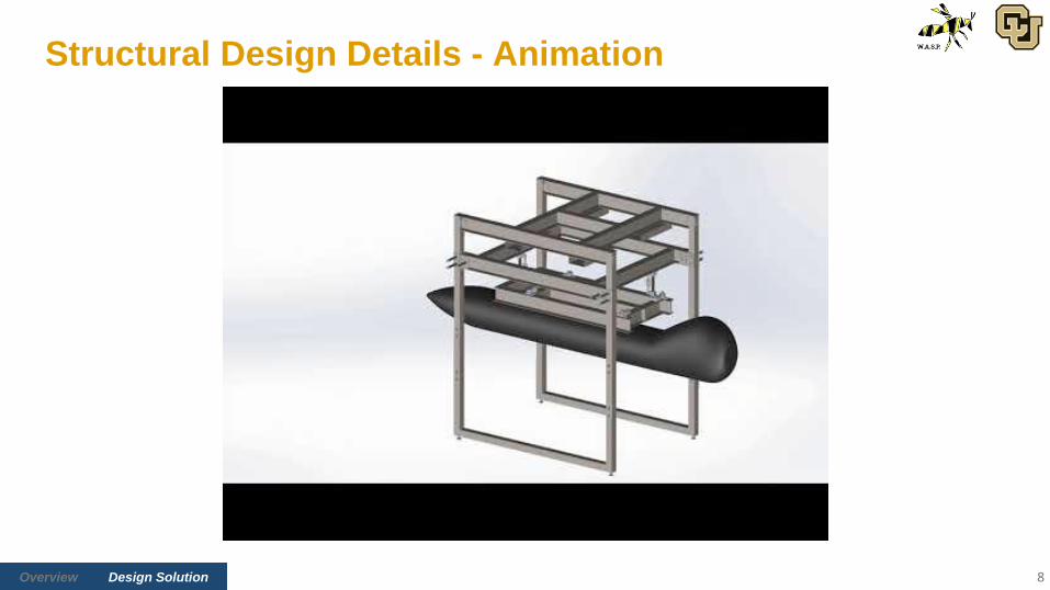
Structural Design Details - Animation
8

Back-upVerification & ValidationProject RisksCPEsDesign Solution Overview Project PlanningRequirements Satisfaction
Functional Block Diagram
9

Back-upVerification & ValidationProject RisksCPEsDesign Solution Overview Project PlanningRequirements Satisfaction
Structural Design - Key Detailed Components
10
Lifting Tilting Pod MountingForce
Measurement
ComponentChain Hoist,
TrolleyHard Stops Lug Mounts
Load Cells,
Socket Joints,
Attachment Blocks
Visual

Back-upVerification & ValidationProject RisksCPEsDesign Solution Overview Project PlanningRequirements Satisfaction
Electronics Functional Block Diagram
11

Back-upVerification & ValidationProject RisksCPEsDesign Solution Overview Project PlanningRequirements Satisfaction
Electronic Hardware Details
12
Hardware List Product Names Specification(s) Value
Load Cells Omega LC103B [8] Accuracy Class C3: ±0.023%
Inclinometer Wyler Clinotronic Plus [10] Limits of Error < 1.5 Arcmin (~ <0.025 deg)
Simultaneous Bridge
ModuleNI 9237 DAQ [14]
Sampling, Signal
Conditioning
50 kS/s (per channel), 8th
order filtering
CompactDAQ
ChassisNI cDAQ 9171 [15]
FIFO size,
Timing Accuracy,
Timing resolution
127 samples, 50 ppm of
sample rate, 12 ns
Omega LC103B Wyler Clinotronic Plus NI 9237 DAQ NI cDAQ 9171

Back-upVerification & ValidationProject RisksCPEsDesign Solution Overview Project PlanningRequirements Satisfaction
User Interface and Software Details
13
Autonomous Data
Collection
Manual Data Collection/
Troubleshooting

Critical Project Elements
14

Back-upVerification & ValidationProject RisksCPEsDesign Solution Overview Project PlanningRequirements Satisfaction
Critical Project Elements
15
CPE Icon Description FR
E1All static possible loading must be handled by the frame. It must be portable and support
at least 2000 lbs.FR3, FR4
E2 WASP should rigidly interface with lugs for all pod types. FR3
E3WASP must be capable of weight measurements with ±0.1% of true value;
CG measurements within ±0.1'' of true value.FR1, FR2
E4 Testing procedures for weight and CG calculations must be well-developed. FR5
E5Since heavy loads are involved, both the pods and WASP operators should be safe from
harm.FR5

Design Requirements Satisfaction
16

Back-upVerification & ValidationProject RisksCPEsDesign Solution Overview Project PlanningRequirements Satisfaction
Driving Requirements
17
Requirement
NumberRequirement Summary CPE Satisfied?
FR1, FR2 Weight and CG Measurement
FR3 Structural Integrity
FR4 Maneuverability
FR5 User Procedure

Back-upVerification & ValidationProject RisksCPEsDesign Solution Overview Project PlanningRequirements Satisfaction
Weight and CG Measurement Accuracy (FR1, FR2)
18
DR 1.1: WASP shall measure the pod weight within a tolerance of ±0.1% of the total pod weight
DR 2.1: WASP shall measure the pod X, Y, & Z CG of each pod with an accuracy of ±0.1 in.
Updates to model since PDR:
● Inclinometer accuracy = ±0.025°, Wyler Clinotronic Plus [10]
● Load Cells Error distribution model○ Mean = 0.0 % FSO○ Std. Dev. = (1/2.4)*(0.02% FSO) [1]
● Worst-case scenario - model evaluated at maximum expected error:
W: 0.18% → 6.7σ
XCG: 0.05 in → 3.0σ
YCG: 0.07 in → 10.4σ
ZCG: 0.14 in → 3.3σ
Load Cell Sensor Full-Span
Pod Weight [lbs] 500 lbs 1000 lbs
200 > 95% > 95%
300 > 95% > 95%
350 > 95% > 95%
400 X > 95%
500 X > 95%
600 X > 95%
700 X > 95%
800 X > 95%
850 X >95%
900 X > 95%
1000 X > 95%
Expected Success Rate for Satisfying Accuracy Requirements for Weight and CG vs. Pod Weight
(From Monte Carlo Simulations with N = 10000)

Back-upVerification & ValidationProject RisksCPEsDesign Solution Overview Project PlanningRequirements Satisfaction
Critical
Component
Min FOS
(FEA)
Min FOS
(BOTE)
Consequence of Failure Visuals
Frame
Cleats3.1 N/A
Mild
Welds attach legs to top
frame as well
Lug Mounts 3.0 3.1
Severe
Pod can fall to the ground
(up to 5 feet).
Structural Integrity (FR3)
19
DR 3.1: WASP shall support pods of 2000 lbs with a FOS of 2.0 to make safe and accurate measurements
Components with Safety Factors Less Than 4.0

Back-upVerification & ValidationProject RisksCPEsDesign Solution Overview Project PlanningRequirements Satisfaction
Leg Cleat - FEA
20
Min Factor of Safety: 3.1
*FEA done in Solidworks Simulation [3]

Back-upVerification & ValidationProject RisksCPEsDesign Solution Overview Project PlanningRequirements Satisfaction
Lug Mounts - FEA
21
Lug Mount Assembly
Min Factor of Safety: 3.0
Isolated Flange
Min Factor of Safety: 3.1
*Assumes one mount supports the entire pod weight

Back-upVerification & ValidationProject RisksCPEsDesign Solution Overview Project PlanningRequirements Satisfaction
x
z
Lug Mounts - BOTE
Flange Bending (Tilted, Cantilevered Beam)
• Part of the force (sin(15)) acts in the x-direction• Due to the 15 degree tilt
• Cantilevered beam problem [4]• Modeled with a point load on the end of the beam• Second area moment of inertia: 0.00383 in4
• Maximum moment: -214.82 lb-in• Maximum normal stress: 11.89 ksi• Safety factor: 3.05• This is a very conservative oversimplification
• The “beam” is not truly free on the bottom• The load is not concentrated at the very edge of the
“beam” as modeled here• Entire pod weight is on one of the two mounts
22
z
x
Design Requirement Minimum Safety Factor Requirement Satisfied
DR 3.1 (FOS > 2.0) 3.05 Yes

Back-upVerification & ValidationProject RisksCPEsDesign Solution Overview Project PlanningRequirements Satisfaction
Structural Integrity (FR3)
23
DR 3.2: The WASP mounting interface shall support all current SNC pod mounting types.
Lug Type 100 lb 1000 lb 2000 lb TP lug
Image
Requirement Satisfied Yes Yes Yes Yes
Lifting Solution Specs Requirement Satisfied
Chain Hoist 4000 lbs Loading Capability Yes
DR 3.3: WASP shall lift pods out of their cradles.

Back-upVerification & ValidationProject RisksCPEsDesign Solution Overview Project PlanningRequirements Satisfaction
Maneuverability (FR4)
24
DR 4.1: WASP shall have a transportation mechanism.
Current Transportation Solution:
Forklift Slots
Future Transportation Solution:
Leveling Caster Wheels

Back-upVerification & ValidationProject RisksCPEsDesign Solution Overview Project PlanningRequirements Satisfaction
User Procedure (FR5)
25
DR 5.1: WASP shall complete a single weight and balance test (defined as the moment after the pod is first loaded until the pod is back in its cradle) in no more than 30 minutes.
Procedure Time
Chain Hoist Lift/Lower 12 mins
Pin Insertion/Removal 10 mins
User Interface & Computation 2 mins
Pod Mount/Demount 6 mins
Total (3 measurement sets) 30 mins
Time-Reducing Design Features:
● Autonomous Software
○ Load Cell data read directly into software for
computation purposes
● Hard Stops
○ Additional tolerances built into pins/pin
houses for easier insertion
● Wyler Clinotronic Plus Inclinometer
○ Accurate within ±0.025° [6]
○ Allows for fewer measurement sets

Back-upVerification & ValidationProject RisksCPEsDesign Solution Overview Project PlanningRequirements Satisfaction
Driving Requirements Satisfaction
26
Requirement
NumberRequirement Summary CPE Satisfied?
FR1, FR2 Weight and CG Measurement Yes
FR3 Structural Integrity Yes
FR4 Maneuverability Yes
FR5 User Procedure Yes

Project Risks
27

Back-upVerification & ValidationProject RisksCPEsDesign Solution Overview Project PlanningRequirements Satisfaction
Risk Scoring Definitions
28
Scoring - Impact
Value Range Level Description
1 Low DRs Met
3 Mild 1 DR Failed
6 Medium More than 1 DR failed
8 High FR(s) Failed
Scoring - Likelihood
Value Range Level Description
1 Low Not Likely
3 Medium Somewhat Likely
8 High Very Likely

Back-upVerification & ValidationProject RisksCPEsDesign Solution Overview Project PlanningRequirements Satisfaction
Risk Table
29
Number Risk Description Effect
1Load Cell Placement
(Manufacturing)● Inaccurate measurements
2Budget Exceeds $5000
(Finance)
● Failure to complete project
● Functional failure
3Structural Component Failure
(Structures)
● Fail accuracy requirements
● Safety concerns
4Structural Interface with Pods via Lug Mounts
(Structures)● Functional failure
5Misalignment of Frame Members from Welding
(Manufacturing)
● Structural failure
● Inaccurate measurements
6Human-Induced Error due to Deviations from Intended Use
(Safety)
● Functional failure
● Safety concerns
7Manufacturing implications due to COVID-19
(Manufacturing)● Can’t manufacture WASP
Super
Critical
Critical

Back-upVerification & ValidationProject RisksCPEsDesign Solution Overview Project PlanningRequirements Satisfaction
Pre-Mitigation Risk Matrix
30
Impact Level
Likelihood
Level
Low Mild Medium High
High 5 1
Medium
2
3 4 6
7
Low
RISK KEY1. Load Cell Placement
2. Budget Exceeds $5000
3. Structural Component Failure
4. Structural Interface with Pods via
Lug Mounts
5. Misalignment of Frame Members
from Welding
6. Human-Induced Error due to
Deviations from Intended Use
7. Manufacturing implications due to
COVID-19

Back-upVerification & ValidationProject RisksCPEsDesign Solution Overview Project PlanningRequirements Satisfaction
Post-Mitigation Risk Matrix
31
Impact Level
Likelihood
Level
Low Mild Medium High
High
Medium
Low
5 1
5 2
1
3 4 6
2
3 4 6
RISK KEY1. Load Cell Placement
2. Budget Exceeds $5000
3. Structural Component Failure
4. Structural Interface with Pods via Lug
Mounts
5. Misalignment of Frame Members from
Welding
6. Human-Induced Error due to
Deviations from Intended Use
7. Manufacturing implications due to
COVID-19
MITIGATION1. Margin for tolerance, Slotted for
adjustability, Manufacturing procedures
2. Finalized master equipment, Management
reserves, Student discount/grad funding
3. Modelling, Testing, Manufacturing
procedures
4. Careful design, Testing/verification
5. Manufacturing procedures, measurements
6. User manual, tag equipment
7. Buffer time, At-home manufacturing,
77
MITIGATION1. Margin for tolerance, Slotted for
adjustability, Manufacturing procedures
2. Finalized master equipment, Management
reserves, Student discount/grad funding
MITIGATION1. Margin for tolerance, Slotted for
adjustability, Manufacturing procedures

Verification & Validation
32

Back-upVerification & ValidationProject RisksCPEsDesign Solution Overview Project PlanningRequirements Satisfaction
Component Validation - Load Cell Characterization
33
● Objective:○ Calibrate software to sensors
○ Confirm load cells perform within accuracy tolerance
● Plan:○ Apply tensile load in 100 lb increments using
Electromechanical MTS machine (Pilot Lab)
○ Record measured force in WASP UI
● Measurements:○ Applied load from MTS machine
○ Measured load from LC103B load cells
● Pass Criteria:○ Load cells measure force within error tolerances
○ Load cell measurements are linear within FSO
DR 1.1.3: Sensors shall be calibrated such that measured values are accurate within ±0.1% of the pod’s true total weight
DR 2.1.3: Sensors shall be calibrated such that measured values are accurate within ±0.1 in. of the pod’s true CG

Back-upVerification & ValidationProject RisksCPEsDesign Solution Overview Project PlanningRequirements Satisfaction
Subsystem Verification - Electronics & Software
34
● Objective:○ Prove functionality of software and compatibility of hardware
○ Verify data acquisition for multiple channels simultaneously
● Plan:○ Connect 3 load cells to WASP DAQ System
○ Extract data from load cell
○ Calibrate NI DAQ System
● Measurements:○ NI 9237 Signals
● Pass Criteria:○ All hardware connected correctly
○ Convert sensor response into data
■ Converts analog input into digital value
○ Filter/sample/amplify signal
DR 8.1: WASP shall have a computer based tool that interfaces with the sensors

Back-upVerification & ValidationProject RisksCPEsDesign Solution Overview Project PlanningRequirements Satisfaction
Subsystem Validation - Structural Integrity
● Objective:○ Verify structure can support pods up to 2000
lbs for all possible CG locations
● Plan:○ Incrementally load up to 1000 lbs
○ Validate/modify SolidWorks FEA model
○ Predict FOS for 2000 lb loads
● Measurements:○ 5 x CEA-06-250UW-350 strain gauges [11]
○ 1000 lb FSO tension load cell
● Pass Criteria:○ No yielding
35
DR 3.1: WASP shall support pods of 2000 lbs with a FOS of 2.0 to make safe and accurate measurements
DR 3.3: WASP shall lift pods out of their cradles

Back-upVerification & ValidationProject RisksCPEsDesign Solution Overview Project PlanningRequirements Satisfaction
System Verification - Measurement Accuracy
36
● Objective:○ Verify successful integration of subsystems
○ Compare Weight & CG measurements
with model
● Plan:○ Perform full test with SNC test article
○ Calibrate WASP
● Measurements:○ Weight & CG
● Pass Criteria: ○ Measured weight within ±0.1%
○ Measured CG within ±0.1 in.
DR 1.1: WASP shall measure the pod weight within a tolerance of ±0.1% of the total pod weight
DR 2.1: WASP shall measure the pod X, Y, & Z CG of each pod with an accuracy of ±0.1 in.

Back-upVerification & ValidationProject RisksCPEsDesign Solution Overview Project PlanningRequirements Satisfaction
System Verification - Operations Tests
37
● Objective: ○ Verify CONOPS
○ Determine test time, engineers required
● Plan:○ Perform full setup of WASP
○ Perform full tests with SNC test article
● Measurements:○ Weight & CG
● Pass Criteria: ○ Accurate test performed with 2 engineers
○ Accurate test performed in 30 minutes
○ Accurate test performed with non-WASP
engineers
DR 5.1: WASP shall complete a single weight and balance test in no more than 30 minutes
DR 5.2: WASP shall require no more than two engineers to complete one test

Project Planning
38

Back-upVerification & ValidationProject RisksCPEsDesign Solution Overview Project PlanningRequirements Satisfaction
WASP Organizational Chart - Fall 2020
39

Back-upVerification & ValidationProject RisksCPEsDesign Solution Overview Project PlanningRequirements Satisfaction
WASP Organizational Chart - Spring 2021
40

Back-upVerification & ValidationProject RisksCPEsDesign Solution Overview Project PlanningRequirements Satisfaction
Manufacturing Plan
41

Back-upVerification & ValidationProject RisksCPEsDesign Solution Overview Project PlanningRequirements Satisfaction
Test NameCPE
Addressed
Scheduling
Location Anticipated Date Hazards or Challenges
Sensor
CharacterizationPilot Lab January 2021
Heavy Loads
(1000 lbs)
E&S Functionality Pilot Lab December 2020 N/A
Structural Machine Shop March 2021Heavy Loads
(1000 lbs)
Accuracy Machine Shop April 2021 N/A
Operations Machine Shop April 2021 N/A
Test Plan
42

Back-upVerification & ValidationProject RisksCPEsDesign Solution Overview Project PlanningRequirements Satisfaction
Cost Plan
43
Subsystems Overview
Subsystem Expenses Percentage
Raw Materials $1,847.85 36.96%
Hardware $1,627.22 32.54%
Electronics $145.68 2.91%
Other Expenses $500.00 10.00%
Management Reserves $879.25 17.59%
Total $5,000.00
Management Reserves $ 879.25
S6x17.25 A36 I-Beam (10' length) $ 164.20 1 $ 164.20
3"x.120" A36 Square Tube (96" length) $ 45.86 1 $ 45.86
Shipping $ 100.00 1 $ 100.00
Extra Fasteners $ 50.00 1 $ 50.00
Manufacturing Consumables $ 200.00 1 $ 200.00
Electrical Connectors $ 50.00 1 $ 50.00
Unallocated Reserves $ 269.19 1 $ 269.19

Back-upVerification & ValidationProject RisksCPEsDesign Solution Overview Project PlanningRequirements Satisfaction
Work Breakdown Structure
44

Back-upVerification & ValidationProject RisksCPEsDesign Solution Overview Project PlanningRequirements Satisfaction 45
Timeline for Spring Semester

Back-upVerification & ValidationProject RisksCPEsDesign Solution Overview Project PlanningRequirements Satisfaction
Acknowledgements
SNC Team:
Becky Vander Hoeven, Gary Hutton, Stephen McLaughlin, Jon Matula, AJ Olson
Advisory Board Members and AES Faculty:
Dr. Allison Anderson, Lara Buri, Dr. Donna Gerren, Camilla Hallin,
Professor Bobby Hodgkinson, Dr. Jelliffe Jackson, Dr. Francisco Lopez Jimenez,
Professor Matt Rhode, Professor Trudy Schwartz,
Dr. Zachary Sunberg, Dr. Kathryn Wingate
CDR Reviewers:
Colin Claytor, Dr. Francisco Lopez Jimenez, Dr. Alireza Doostan, Dr. Aaron Johnson,
Dr. Kurt Maute, Team NanoSAM II, Team VORTEX
Thank you to everyone who supported the WASP Team!
46

Questions?
47

Back-upVerification & ValidationProject RisksCPEsDesign Solution Overview Project PlanningRequirements Satisfaction
References[1] ASTM E74-13a, Standard Practice of Calibration of Force-Measuring Instruments for Verifying the Force Indication of
Testing Machines, ASTM International, West Conshohocken, PA, 2013, www.astm.org
[2] Brown, Kevin H, et al. Sandia Corporation, 2008, pp. 28–30, Guideline for Bolted Joint Design and Analysis
[3] Dassault Systems, SolidWorks. 2020
[4] Hibbeler, R. C. Statics and Mechanics of Materials. 5th ed., Pearson Education South Asia, 2017.
[5] Markovich, Emma et. al. WASP Preliminary Design Review. Oct. 2020. PowerPoint Presentation.
[6] Maute, K. and Lopez Jimenez, F. “Chapter 10: Beam Deflections: Second Order Method.” ASEN 3112 - Structures Lecture
Notes.
[7] MMPDS-13: Metallic Materials Properties Development and Standardization (MMPDS). Federal Aviation Administration,
2018.
[8] Omega, “500 lbf, ±0.02%, Linearity, 3 mV/V Output, Cable,” LC103B-500. https://www.omega.com/en-us/force-strain-
measurement/load-cells/p/LC103B
[9] “Properties of ASTM A36 Steel Bars.” ASTM A36 Steel, Bar,
www.matweb.com/search/DataSheet.aspx?MatGUID=d1844977c5c8440cb9a3a967f8909c3a.
[10] WYLER AG, “Operator’s Manual Clinotronic Plus,” clino_e.doc, 26 April 2016.
48

Back-upVerification & ValidationProject RisksCPEsDesign Solution Overview Project PlanningRequirements Satisfaction
References
[11] Vishay Precision Group, “Precision Strain Gauges and Sensors Databook”, micro-measurements.com, 3, February 2016.
[12] Vishay Precision Group, “Optimizing Strain Gauge Excitation Levels”,micro-measurements.com, 1, November 2010.
[13] Columbus McKinnon, “Factors to Consider When Selecting a Hoist”, columbusmckinnon.com, 17, February 2020.
[14] National Instruments, “NI 9237,” NI 9237, November 2015. https://www.ni.com/pdf/manuals/374186a_02.pdf
[15] National Instruments, “NI cDAQ-9171,” July 2016. https://www.ni.com/pdf/manuals/374037b.pdf
[16] “66" x 50" Short Bed Truck Cargo Net with Cam Buckles & S-Hooks,” US Cargo Control, 22 November 2020. Short Bed
Truck Cargo Net - 66"x50" - Black Webbing (uscargocontrol.com)
49

Supporting Material
50

Back-upVerification & ValidationProject RisksCPEsDesign Solution Overview Project PlanningRequirements Satisfaction
Acronym List
51
Acronym Definition
ACC Accuracy
BC Boundary Conditions
BOTE Back of the Envelope (Hand-derived)
CAD Computer-Aided Design
CG Center of Gravity
COMPAT Compatibility
CONOPS Concept of Operations
COTS Consumer Off-The-Shelf
Acronym Definition
CPE Critical Project Element
DAQ Data Acquisition System
DR Design Requirement
E&S Electronics and Software
FEA Finite Element Analysis
FOS Factor of Safety
FSO Full Span of Operation
FR Functional Requirement

Back-upVerification & ValidationProject RisksCPEsDesign Solution Overview Project PlanningRequirements Satisfaction
Acronym List
52
Acronym Definition
GUI Graphical User Interface
IAS ISR, Aviation & Security
ISR Intelligence, Surveillance, &
Reconnaissance
NIST National Institute of Standards and
Technology
Acronym Definition
PDR Product Design Review
SNC Sierra Nevada Corporation
TP Third Party
UI User Interface
VBA Visual Basic for Applications
WASP Weight Analysis of Surveillance Pods

Back-upVerification & ValidationProject RisksCPEsDesign Solution Overview Project PlanningRequirements Satisfaction
Key Terms Definition
53
Term Definition
Frame The outer physical structure of WASP
ISR Pod/Pod The physical object being measured by WASP, given by SNC.
Measurement Set One recorded value for each sensor (load and inclination) in the flat and
tilted configurations.
Test The execution of a full procedure which starts after set-up and concludes
when weight and CG values are output.
Tool Equivalent to WASP.
User Procedure Instructions document that describes transportation, maneuvering, and
testing process for test engineers.
WASP All elements of the final product/deliverable.

Structural Design
54

Back-upVerification & ValidationProject RisksCPEsDesign Solution Overview Project PlanningRequirements Satisfaction
Structural Design - Isometric
55

Back-upVerification & ValidationProject RisksCPEsDesign Solution Overview Project PlanningRequirements Satisfaction
Structural Design - Basic Dimensions
56

Back-upVerification & ValidationProject RisksCPEsDesign Solution Overview Project PlanningRequirements Satisfaction
Structural Design - Outer Frame
57

Back-upVerification & ValidationProject RisksCPEsDesign Solution Overview Project PlanningRequirements Satisfaction
Structural Design - Sliding Interface
58

Back-upVerification & ValidationProject RisksCPEsDesign Solution Overview Project PlanningRequirements Satisfaction
Structural Design - Level Testbed
59

Back-upVerification & ValidationProject RisksCPEsDesign Solution Overview Project PlanningRequirements Satisfaction
Structural Design - Tilted Testbed
60

Back-upVerification & ValidationProject RisksCPEsDesign Solution Overview Project PlanningRequirements Satisfaction
Structural Design - Link to Mechanical Drawings
61
https://drive.google.com/drive/u/0/folders/1pGDeZoZGyrDvD-Qb2tOPaOz1nWZPimzU

Back-upVerification & ValidationProject RisksCPEsDesign Solution Overview Project PlanningRequirements Satisfaction
Structural Design - Sliding Interface Force Sensor Attachment Block
62
● Slots in bolt holes allow for some error in manufacturing to be tolerated

Back-upVerification & ValidationProject RisksCPEsDesign Solution Overview Project PlanningRequirements Satisfaction
Structural Design - Safety Concept
• Can be attached to the legs of the outer frame
• Preliminary research:• Custom dimension orders can be made• Web breaking strength of 10000 lbs [16]
• If any structural components break, this system can either catch the pod or significantly reduce the energy with which it will hit the floor
63

Structural Analysis
64

Back-upVerification & ValidationProject RisksCPEsDesign Solution Overview Project PlanningRequirements Satisfaction
Structural Analysis - Overall
Analyses
• BOTE• Beam bending• Weld strength
65

Back-upVerification & ValidationProject RisksCPEsDesign Solution Overview Project PlanningRequirements Satisfaction
Overall Analyses - BOTE
Beam Bending
• This analysis is practically the same as it was for PDR with some updates - see the WASP PDR [5] for more information
• Geometry and load cases have slightly changed• The beam numbering has been updated
66
Sliding InterfaceTestbed Top Frame and Legs

Back-upVerification & ValidationProject RisksCPEsDesign Solution Overview Project PlanningRequirements Satisfaction
Overall Analyses - BOTE
Weld Strength
• The same welds are used on the sliding interface and testbed
Assumptions:
• Weld length: Lw = 8.75” (actual 21”)• Weld yield strength: ƒw = 64000 psi• Max load: P = 2500 lbs• Weld area is a conservative: a = ¼”
Results:
• FOS: 40
67
Equations:
ƒv = P/(0.707*Lw*a)
FOS = ƒw/ƒv

Back-upVerification & ValidationProject RisksCPEsDesign Solution Overview Project PlanningRequirements Satisfaction
Overall - Results
68
Analysis Displacement (in) Maximum Stress (ksi) Safety Factor
Weld Bead N/A 1.60 40
Beam 1 0.0066 2.27 16
Beam 2 0.0011 1.91 19
Beam 3 0.0176 3.30 15
Beam 4 0.0099 2.59 14
Beam 5 0.0114 3.99 9.1
Beam 6 0.0050 0.698 52
Beam 7 0.0132 0.955 38
Beam 8 0.0008 0.981 37
Beam 9 0.0029 2.79 13
Beam 10 0.0004 0.908 40

Back-upVerification & ValidationProject RisksCPEsDesign Solution Overview Project PlanningRequirements Satisfaction
Structural Analysis - Top Frame + Legs
Analyses
• BOTE• Leg compression and buckling• Cleat bolt shear
• FEA (SolidWorks Simulation)• Beam-leg cleats• Leveling Feet Mounting Plates• Top frame FEA
69

Back-upVerification & ValidationProject RisksCPEsDesign Solution Overview Project PlanningRequirements Satisfaction
Top Frame + Legs - BOTE
Leg Compression and Buckling
• As with beam bending, this analysis is practically the same as it was for PDR with some updates - see the WASP PDR [4] for more information
70

Back-upVerification & ValidationProject RisksCPEsDesign Solution Overview Project PlanningRequirements Satisfaction
Top Frame + Legs - BOTE
Leg-Beam Cleat Bolt Shear
• Ignore the threads when calculating cross-sectional area: minor area (conservative)
• Ignores welds holding the legs to the upper beams
• A_c = 0.0269 in^2• Load: 333 lbs• Shear stress: 12.4 ksi• Safety Factor: 7.0
71

Back-upVerification & ValidationProject RisksCPEsDesign Solution Overview Project PlanningRequirements Satisfaction
Leg Cleat - FEA
72
Max Displacement: 0.0008in
Min Factor of Safety: 3.1
Max Stress: 11.6 ksi

Back-upVerification & ValidationProject RisksCPEsDesign Solution Overview Project PlanningRequirements Satisfaction
Leveling Feet Mounting Plates
73
Min Factor of Safety: 4.7

Back-upVerification & ValidationProject RisksCPEsDesign Solution Overview Project PlanningRequirements Satisfaction
Top Frame - FEA
74
Max Displacement: 0.0165in
Min Factor of Safety: 7.4
Max Stress: 4.93ksi
Back-upVerification & ValidationProject RisksCPEsDesign Solution Overview Project PlanningRequirements Satisfaction
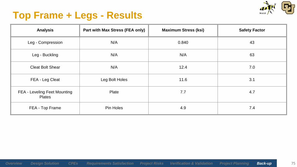
Top Frame + Legs - Results
75
Analysis Part with Max Stress (FEA only) Maximum Stress (ksi) Safety Factor
Leg - Compression N/A 0.840 43
Leg - Buckling N/A N/A 63
Cleat Bolt Shear N/A 12.4 7.0
FEA - Leg Cleat Leg Bolt Holes 11.6 3.1
FEA - Leveling Feet Mounting
Plates
Plate 7.7 4.7
FEA - Top Frame Pin Holes 4.9 7.4

Back-upVerification & ValidationProject RisksCPEsDesign Solution Overview Project PlanningRequirements Satisfaction
Structural Analysis - Sliding Interface
Analyses
• BOTE• Pin shear• Bending of pin plate
• FEA• Pin plate• Full sliding interface
76

Back-upVerification & ValidationProject RisksCPEsDesign Solution Overview Project PlanningRequirements Satisfaction
Sliding Interface - BOTE
Sliding interface pin shear
• Simple shear in pin due to load and plates• Symmetric; Simple beam analysis with point loads• 1144 Carbon Steel - 87000 psi yield strength• Load on Pin = Max total load/4
• Plates offer reaction forces (Reaction (each plate) = Load on Pin/2)• Maximum stress = 5793 psi (bending/Flexure Formula)• Maximum load = 700 lb• Safety Factor = 15.52• Diameter of Pin = 0.5 inches
77

Back-upVerification & ValidationProject RisksCPEsDesign Solution Overview Project PlanningRequirements Satisfaction
Sliding Interface - BOTE
Bending of pin plates
• Plates simplified to beam• Only looking at section of plate with applied and reaction
forces/moments• Maximum Load: 350 lb (½ of total load in pin)• Maximum Stress: 1659.3 psi (bending)• 1144 Carbon Steel - 87000 psi yield strength• Safety Factor: 52.4
78

Back-upVerification & ValidationProject RisksCPEsDesign Solution Overview Project PlanningRequirements Satisfaction
Sliding Interface Plate - FEA
79
Max Displacement: 0.00004in Max Stress: 2.32ksi
Min Factor of Safety: 21

Back-upVerification & ValidationProject RisksCPEsDesign Solution Overview Project PlanningRequirements Satisfaction
Sliding Interface - FEA
80
Max Displacement: 0.0091in Max Stress: 13.5ksi
(Pin Holes)
Min Factor of Safety: 12
(Stress Concentration Ignored)

Back-upVerification & ValidationProject RisksCPEsDesign Solution Overview Project PlanningRequirements Satisfaction
Sliding Interface - Results
81
Analysis Part with Max Stress (FEA only) Maximum Stress (ksi) Safety Factor
Sliding Interface Pin Shear N/A 5.79 15.5
Sliding Plate Bending N/A 1.70 52
FEA - Sliding Plate Middle Pinhole 2.3 21
FEA - Sliding Interface Pinholes* 13.5 12 (4.3 Ignored by inaccurate
stress concentration)
*This analysis did not model the welds on the sliding plate - it is very conservative

Back-upVerification & ValidationProject RisksCPEsDesign Solution Overview Project PlanningRequirements Satisfaction
Structural Analysis - Testbed
Analyses:
• BOTE• Level pin shear• Level pin bending• Hard stop rod axial loading
• FEA• Leveling pins and housings• Full testbed
82

Back-upVerification & ValidationProject RisksCPEsDesign Solution Overview Project PlanningRequirements Satisfaction
Testbed - BOTE
Level pin shear
• Simple shear• 1144 Carbon Steel
• Normal yield stress of 87000 psi
• ¾” diameter pins: A_c = 0.442 in^2• Maximum load: 735 lbs• Maximum stress: 1.66 ksi• Safety factor: 29.8
83

Back-upVerification & ValidationProject RisksCPEsDesign Solution Overview Project PlanningRequirements Satisfaction
Testbed - BOTE
Level pin bending
• The space between the pin houses raises bending concerns• Model as a cantilevered beam from the end of the outer pin
house to the beginning of the inner pin house• Force: 735 lbs• Maximum bending stress: 1.25 ksi• Safety Factor: 67
84

Back-upVerification & ValidationProject RisksCPEsDesign Solution Overview Project PlanningRequirements Satisfaction
Testbed - BOTE
Hard stop rod: axially loaded
• Maximum load: 710 lbs• Rod is Grade 8 Steel
• Yield stress of 150000 psi
• ½” diameter, A_c = 0.196 in^2• Maximum stress: 3.62 ksi• Safety factor: 41.5
85

Back-upVerification & ValidationProject RisksCPEsDesign Solution Overview Project PlanningRequirements Satisfaction
Testbed - FEA
Level pins and pin housing
86
Min Factor of Safety: 4.6

Back-upVerification & ValidationProject RisksCPEsDesign Solution Overview Project PlanningRequirements Satisfaction
Testbed - FEA
87
Min Factor of Safety: 8.5
Max Displacement: 0.005 in
Max Stress: 4.2 ksi

Back-upVerification & ValidationProject RisksCPEsDesign Solution Overview Project PlanningRequirements Satisfaction
Testbed - Results
88
Analysis Part with Max Stress (FEA only) Maximum Stress (ksi) Safety Factor
Level Pin Shear N/A 1.6 31
Level Pin Bending N/A 1.3 67
Hard Stop Rod Axial Loading N/A 3.6 41.5
FEA - Pin and Pin Housing Outer Testbed Pin House 11.6 4.6
FEA - Tilted Testbed (Pinned) Outer Testbed 4.2 8.5
FEA - Tilted Testbed (Lifting) Outer Testbed 5.5 5.0
FEA - Flat Testbed (Pinned) Pins 10 6.0
FEA - Flat Testbed (Lifting) Pins 0.86 10

Back-upVerification & ValidationProject RisksCPEsDesign Solution Overview Project PlanningRequirements Satisfaction
Structural Analysis - Lug Mounts
Analyses:
• BOTE• Bending of top plate • Bending of the lug pin (level)• Shear in the flange (level)• Axial load in flange sides (level)• Bending of the flange bottom (level)• Bending of the flange side (tilted)
• Fixed-fixed (Best case)• Cantilevered (Worst case)
• FEA (level and tilted configurations)• Lug mount (flange and top plate)• Lug mount flange• Lug pins
89

Back-upVerification & ValidationProject RisksCPEsDesign Solution Overview Project PlanningRequirements Satisfaction
Lug Mounts - BOTE
Lug Plate Bending
• ⅜” thick, 4” long, 3.5” wide• Second-order bending analysis [6]
• Assuming free ends and symmetry
• Maximum bending moment: -500 lb-in• Maximum bending stress: 5.3 ksi• Safety factor: 6.807
90

Back-upVerification & ValidationProject RisksCPEsDesign Solution Overview Project PlanningRequirements Satisfaction
Lug Mounts - BOTE
Lug Pin Bending (Level Case)
• Geometry depends on lug mount type (100lb, 1000lb, 2000lb class)
• F will be half the weight of the pod in the level case
• Second-order bending analysis, assuming pinned ends and symmetry
• Very low second area moments of inertia• I_x = 0.01063 in^4 for the 1000lb lug pin
• Maximum bending moment: -243.75lb-in• Maximum bending stress: 6.88ksi• Lowest safety factor: 5.28 (1000lb lug pins)
91

Back-upVerification & ValidationProject RisksCPEsDesign Solution Overview Project PlanningRequirements Satisfaction
Lug Mounts - BOTE
Flange Shear (Level)
• Directly related to bending problem (2 slides ahead of this one)
• Double shear• Cross Sectional Area is 0.249 in^2• Shear Stress = 0.58 Normal Stress (Steel)• Max shear force: 500lb• Max shear stress: 2.01 ksi• Safety factor: 10.48
92

Back-upVerification & ValidationProject RisksCPEsDesign Solution Overview Project PlanningRequirements Satisfaction
Lug Mounts - BOTE
Flange Axial Load (Level)
• Sides of flange are in tension• Cross Sectional Area on each side is 0.51 in^2• Maximum shear force per side: 500lb• Maximum normal stress: 1.20 ksi• Safety factor: 60.40
93

Back-upVerification & ValidationProject RisksCPEsDesign Solution Overview Project PlanningRequirements Satisfaction
Lug Mounts - BOTE
Flange Bending (Level)
• Reaction force and moment on each side• Second order bending problem: fixed-fixed• Modeled with the load distributed across the bottom
rather than being a single point at the center• Maximum moment: -75 lb-in• Maximum normal stress: 4.36 ksi• Safety factor: 8.33
94

Back-upVerification & ValidationProject RisksCPEsDesign Solution Overview Project PlanningRequirements Satisfaction
Lug Mounts - BOTE
Flange Bending (Tilted, Fixed-Fixed)
• Part of the force (sin(15)) acts in the y-direction• Second order bending problem: fixed-fixed• Modeled with the load distributed across the left
slide• Maximum moment: -18.59 lb-in• Maximum normal stress: 1.03 ksi• Safety factor: 35.19• This is a favorable over-simplification
• Stark contrast to the BOTE shown in the main slides
95
x
z
z
x

Back-upVerification & ValidationProject RisksCPEsDesign Solution Overview Project PlanningRequirements Satisfaction
Lug Mounts - FEA (Level Case)
96
Lug Mount Assembly
Min Factor of Safety: 6.3
Isolated Flange
Min Factor of Safety: 6.1
Lug Mount FEA assumes 50% of the pod weight rests on each mount when level

Back-upVerification & ValidationProject RisksCPEsDesign Solution Overview Project PlanningRequirements Satisfaction
Lug Mounts - FEA
97
Lug Pin (Level Loading)
Min Factor of Safety: 6.9
Lug Pin (Tilted Loading)
Min Factor of Safety: 4.4
1000 lb lug pins shown here because they are the limiting case. Analyses on the 100 lb and 2000 lb pins were completed as well.

Back-upVerification & ValidationProject RisksCPEsDesign Solution Overview Project PlanningRequirements Satisfaction
Lug Mounts - Results
98
Analysis Part with Max Stress (FEA only) Maximum Stress (ksi) Safety Factor
Bending of Top Plate N/A 5.3 6.8
Bending of Lug Pin* N/A 6.88 5.28
Shear in the Flange (Level) N/A 2.0 11
Axial Load in the Flange (Level) N/A 1.96 19
Bending in the Flange Bottom (Level) N/A 4.4 8.3
Bending in the Flange Side (Tilted) - Fixed-fixed N/A 1.03 35
Bending in the Flange Side (Tilted) - Cantilevered N/A 11.9 3.1
FEA - Level Lug Mount Assembly Flange (2000 lb) 5.76 6.3
FEA - Tilted Lug Mount Assembly Flange (2000 lb) 9.08 4.0
FEA - Level Lug Mount Isolated Flange Flange (2000 lb) 5.95 6.1
FEA - Tilted Lug Mount Isolated Flange Flange (2000 lb) 8.64 4.2
FEA - Lug Pin in Level Configuration Lug Pin (1000 lb) 5.26 6.9
FEA - Lug Pin in Tilted Configuration Lug Pin (1000 lb) 8.25 4.4
*For the lug pin, the 1000lb pin had the lowest safety factor. For all other analyses, the 2000lb mount had the worst safety factors. The analyses shown here are for the worst case (i.e. FEA of 2000 lb lug pin is not shown
because it was safer than the 1000 lb lug pin)

Back-upVerification & ValidationProject RisksCPEsDesign Solution Overview Project PlanningRequirements Satisfaction
Structural Integrity - Summary
99
DR 3.1: WASP shall support pods of 2000 lbs with a FOS of 2.0 to make safe and accurate measurements
Assembly Minimum
FOS
Part(s) Function
Frame 3.1 Beam-Leg Cleats Connect top frame beams to legs
Sliding Interface 4.3 I-Beam #6 Houses sliding interface pins and plates
Testbed 5.0 Outer Testbed Connects testbed to sliding interface via load
cells
Lug Mounts 3.0 2000 lb Lug Mount
Flange
Hold lug pins in place

Back-upVerification & ValidationProject RisksCPEsDesign Solution Overview Project PlanningRequirements Satisfaction
Structural Analysis - Bolt Engagement
Analyses:
• Axial loading safety factor• Minimum length required for bolt to break before threads tear (Ke)• Relevant equations shown here. See [2] for more details.
100
Back-upVerification & ValidationProject RisksCPEsDesign Solution Overview Project PlanningRequirements Satisfaction
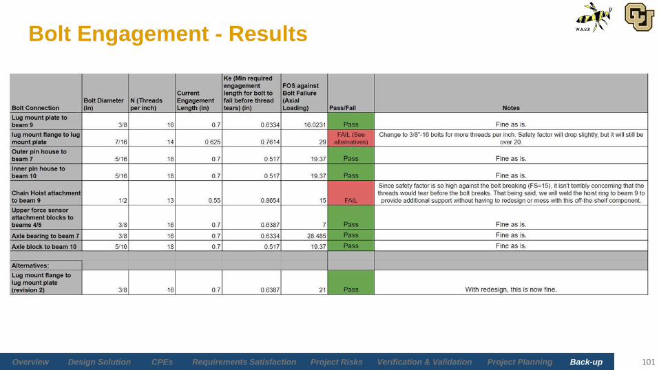
Bolt Engagement - Results
101

Electronics Hardware
102

Back-upVerification & ValidationProject RisksCPEsDesign Solution Overview Project PlanningRequirements Satisfaction
Omega LC103B Load Cells [8]
103

Back-upVerification & ValidationProject RisksCPEsDesign Solution Overview Project PlanningRequirements Satisfaction
Wyler AG Clinotronic Plus [10]
104

Back-upVerification & ValidationProject RisksCPEsDesign Solution Overview Project PlanningRequirements Satisfaction
NI 9237 Bridge Module [14]
105
http://www.ni.com/pdf/manuals/374186a_02.pdf

Back-upVerification & ValidationProject RisksCPEsDesign Solution Overview Project PlanningRequirements Satisfaction
NI 9237 Pinout/ Signal Descriptions [14]
106
Back-upVerification & ValidationProject RisksCPEsDesign Solution Overview Project PlanningRequirements Satisfaction
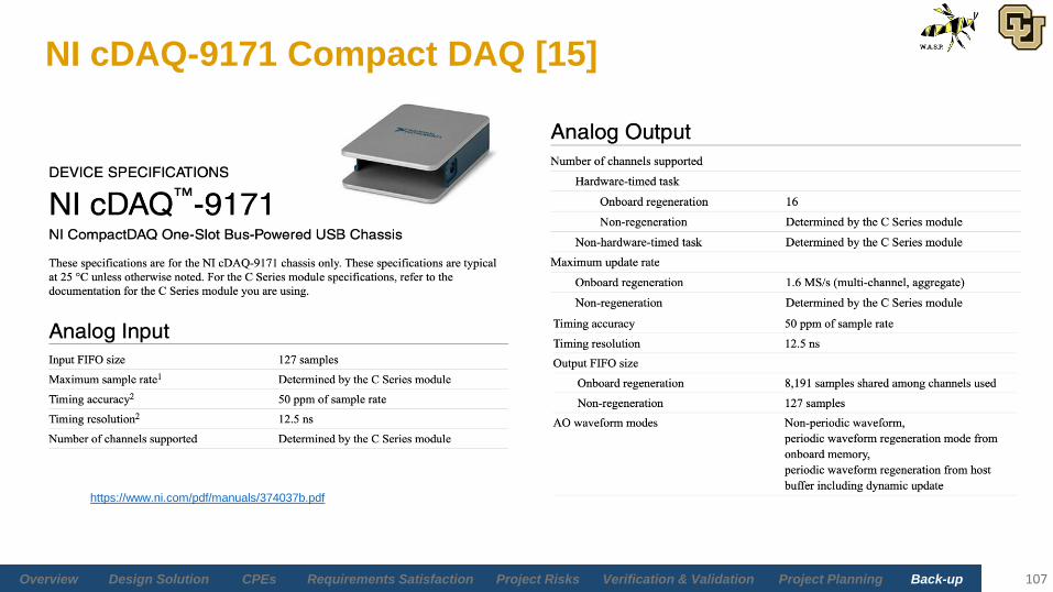
NI cDAQ-9171 Compact DAQ [15]
107
https://www.ni.com/pdf/manuals/374037b.pdf

Risk Analysis

Back-upVerification & ValidationProject RisksCPEsDesign Solution Overview Project PlanningRequirements Satisfaction
Risk Table
109
Risk Description Effect Mitigation
MAN-LCP: Load Cell Placement(Manufacturing)
If sensors are placed poorly, then undesired
non-axial forces may be applied to sensors
Load cell failure, inaccurate
measurements
Having precise manufacturing plans and
confirming load cell measurements with
various measurement techniques
MAN-W: Misalignment from Welding
(Manufacturing)
If welding leads to are misalignment of frame
and/or legs, then accuracy in CG location
may not be within desired threshold;
structure could fail
Structural failure, inaccurate
measurements
Careful manufacturing of the welds, following
detailed manufacturing procedures,
measurement techniques to improve CG
accuracy
STR-CF: Structural Component
Failure
(Structures)
Any failure to components to WASP
(alignment errors, deformation, etc.)
Can cause WASP to fail
requirements (accuracy) if failure
is severe; safety concerns
Careful modelling, testing components and
structural integrity as well as detailed
manufacturing instructions
POD-INT: Structural Interface with
Pods
(Structures)
Any inabilities that cause WASP to not attach
to the lug mounts
(misalignment, sizing errors, etc.)
If not attached property, it can
cause functional failure
Careful design of lug mounts,
testing/verification of lug connections
HUM-ERR: Human User Error
(Safety)
Any human-induced error which can cause
WASP to fail (incorrect attachment of lug
mounts, pins are not inserted properly, etc.)
Functional failure of WASP as
well as possible human injury
Implementation of detailed user manual,
safety indicators on parts of WASP
COST: Budget Exceeds $5000
(Finance)
The maximum expenditures for the project
cannot exceed the $5000
Failure to complete project;
functional requirements failed
Extra precautions will be taken during
manufacturing of structural components;
precise inventory will be done and
implementation of management reserves

Back-upVerification & ValidationProject RisksCPEsDesign Solution Overview Project PlanningRequirements Satisfaction
Risks - Electronics & Software
110
Risk Description Effect Mitigation
LC-Err: Load Cell Error
Greater than Reported on
Data Sheet
Combined error is reported; error
isn’t broken down (creep,
repeatability). This may
overestimate error values
WASP could fail
weight and CG
accuracy
requirements
Testing load cell(s) accuracy
to provide confidence in
error
Inc-Err: Inclinometer Error
Greater than Reported on
Data Sheet
Data sheet may overestimate error
values when measuring angle
between testbed and floor angle
WASP could fail CG
accuracy
requirements
Geometry method to
determine test bed angle
ES-COMMS: Electronics
and Software System
Communication Interruption
Communications within the E&S
system can be interrupted by many
sources
Data will not arrive to
post-processing tool
correctly
Detailed instructions for
hardware set-up as well as
E&S functionality tests
DMG-DAS: Damage to Data
Acquisition System
Any forms of damage to the DAS
(dropping, incorrect pin placement,
ect.)
Data processing will
not be possible
DAS is set-up in a safe
location and detailed
instructions for set-up and
transport is provided

Back-upVerification & ValidationProject RisksCPEsDesign Solution Overview Project PlanningRequirements Satisfaction
Risk Matrices - Electronics & Software
111
Pre-Mitigation
Post-Mitigation
Impact Level
Likelihood
Level
Low Mild Medium High
High
MediumInc-Err
LC-Err
ES-COMMS
DMG-DAS
Low
Impact Level
Likelihood
Level
Low Mild Medium High
High
Medium
LowInc-Err
LC-Err
ES-COMMS
DMG-DAS

Back-upVerification & ValidationProject RisksCPEsDesign Solution Overview Project PlanningRequirements Satisfaction
Risks - Structures
112
Risk Description Effect Mitigation
STR-CF: Structural
Component Failure
Any failure to components to
WASP (alignment errors,
deformation, ect.)
Can cause WASP to fail
requirements (accuracy) if
failure is severe; safety
concerns
Careful modelling, testing
components and structural
integrity as well as detailed
manufacturing instructions
POD-INT: Structural
Interface with Pods
Any inability for WASP to
rigidly attach to the lug
mount
(misalignment, sizing errors,
ect.)
If not attached property, it
can cause functional failure
Careful design of lug
mounts, testing/verification
of lug connections
STR-FAT: Structural Fatigue
Failure due to WASP
bearing loads up to 2000 lbs
for many cycles
Can cause structural
damage and pose safety
concerns; functional failure
Design so FOS is very high
and validate by testing; limit
amount of tests per year
Back-upVerification & ValidationProject RisksCPEsDesign Solution Overview Project PlanningRequirements Satisfaction
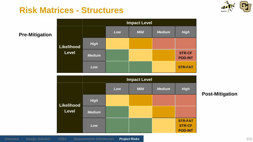
Risk Matrices - Structures
113
Pre-Mitigation
Post-Mitigation
Impact Level
Likelihood
Level
Low Mild Medium High
High
MediumSTR-CF
POD-INT
Low STR-FAT
Impact Level
Likelihood
Level
Low Mild Medium High
High
Medium
Low
STR-FAT
STR-CF
POD-INT

Back-upVerification & ValidationProject RisksCPEsDesign Solution Overview Project PlanningRequirements Satisfaction
Risks - SEIT/Miscellaneous
114
Risk Description Effect Mitigation
DMG-P: Damage to SNC Pod during
operation
Any internal or external damage to
SNC pods
Any damage is categorized
as functional failure
Operators must follow manual; make
sure pod in mounted correctly
COST: Budget exceeds 5000 dollarsThe maximum expenditures for the
project cannot exceed the $5000
Failure to complete project;
functional requirements
failed
Extra precautions will be taken during
manufacturing of structural
components; precise inventory will be
done; implementation of management
reserves
COST-B: I-beam manufacturing errorAny damage done to any I-beam
that prohibits use of them
If significant damage is
done, new beams must be
purchases
Extra precautions will be taken during
manufacturing of I-beams;
implementation of management
reserves

Back-upVerification & ValidationProject RisksCPEsDesign Solution Overview Project PlanningRequirements Satisfaction
Risk Matrices - SEIT/Miscellaneous
115
Pre-Mitigation
Post-Mitigation
Impact Level
Likelihood
Level
Low Mild Medium High
High
MediumCOST
COST-B
Low DMG-P
Impact Level
Likelihood
Level
Low Mild Medium High
High
MediumCOST
COST-B
Low DMG-P

Back-upVerification & ValidationProject RisksCPEsDesign Solution Overview Project PlanningRequirements Satisfaction
Risks - Safety
116
Risk Description Effect Mitigation
HUM-SAF: Human User SafetyInjury to the operators or engineers
using WASP.
Harm the user ranging from
minor injuries to catastrophic
injuries. Although larger
injuries are less likely as
minor injuries.
Safety aspects including an intensive
user safety manual, safety gear, and
safety measures are taken into
consideration.
HUM-ERR: Human User Error
The possibility of the user making a
mistake while dealing with WASP.
Human errors can occur while
completely tests as transporting
WASP.
Can render the structure of
WASP useless if the user
makes an error that breaks a
component. Human error
can also harm the user.
Mitigation includes implementing a
user manual that is easy to
understand and safety measures
aboard WASP like warning labels to
ensure the user knows to be careful.

Back-upVerification & ValidationProject RisksCPEsDesign Solution Overview Project PlanningRequirements Satisfaction
Risk Matrices - Safety
117
Pre-Mitigation
Post-Mitigation
Impact Level
Likelihood
Level
Low Mild Medium High
High
Medium HUM-SAF HUM-ERR
Low
Impact Level
Likelihood
Level
Low Mild Medium High
High
Medium
Low HUM-SAF HUM-ERR

Back-upVerification & ValidationProject RisksCPEsDesign Solution Overview Project PlanningRequirements Satisfaction
Risks - Manufacturing
118
Risk Description Effect Mitigation
MAN-LCP: Load Cell Placement
If sensors are placed poorly, then
undesired non-axial forces may be
applied to sensors
Load cell failure, inaccurate
measurements
Having precise manufacturing plans
and confirming load cell
measurements with various
measurement techniques
MAN-W: Misalignment from Welding
If welds are misaligned, then
accuracy in CG location may not
be within desired threshold;
structure could fail
Structural failure, inaccurate
measurements
Careful manufacturing of the welds;
following detailed manufacturing
procedures; measurement techniques
to improve CG accuracy
MAN-BB: Beam-Beam Connections
If beam-beam connections are
poorly welding, then connection
integrity can be decreased
Structural failure, inaccurate
measurements
Weld analysis; detailed manufacturing
plan;
MAN-SCH: Schedule
Manufacturing is expected to take
a long time which may cause the
construction of WASP to not be
completed on time
Incompletion of projectManufacturing plan with timeline and
planning with Prof. Rhode

Back-upVerification & ValidationProject RisksCPEsDesign Solution Overview Project PlanningRequirements Satisfaction
Risk Matrices - Manufacturing
119
Pre-
Mitigation
Post-
Mitigation
Impact Level
Likelihood
Level
Low Mild Medium High
High MAN-W MAN-LCP
Medium MAN-BB MAN-SCH
Low
Impact Level
Likelihood
Level
Low Mild Medium High
High
MediumMAN-SIP
MAN-W
LowMAN-BB
MAN-SCH

Back-upVerification & ValidationProject RisksCPEsDesign Solution Overview Project PlanningRequirements Satisfaction
Load Cell Placement Error Sensitivity
120

Verification & Validation

Back-upVerification & ValidationProject RisksCPEsDesign Solution Overview Project PlanningRequirements Satisfaction
Sensor Characterization Test Details
• Materials• E&S
• NI 9237 DAQ bridge module (on loan from AES) • NI 9171 cDAQ (on loan from AES) • 3 x 500 lbs FSO Omega LC103B tensile load cell (SNC Purchase)• 3 x 1000 lbs FSO Omega LC103B tensile load cell (SNC Purchase)• Computer to run GUI (internal)
• External Hardware• Instron MTS tensile testing machine (Pilot Lab)
• Safety Equipment• Eye protection
122

Back-upVerification & ValidationProject RisksCPEsDesign Solution Overview Project PlanningRequirements Satisfaction
Sensor Characterization Procedure
123
1 Connect one of the 500 lbs FSO sensors to the NI 9237 bridge module.
2 Connect NI 9237 bridge module to cDAQ, connect cDAQ to computer. Open WASP GUI
3 Insert load cell into Instron MTS machine using appropriate grips.
4 Zero load cell readings in WASP software. Verify GUI is reading load cell data.
5 Apply 100 lbs to the load cell using the MTS machine software.
6 Calibrate sampling in WASP software until measured output fits within 100 lbs ± 0.1 lbs
7 Unload the load cell using the MTS machine software.
8Incrementally load the load cell in 10 evenly spaced increments up to the FSO. At each load, wait 5 seconds and record the measured load
cell data in the WASP GUI. Also record the MTS machine data using the MTS machine software.
9Unload the load cell. Unclamp the load cell and remove from the MTS machine. Disconnect the load cell from the NI 9237 bridge module.
10 Repeat steps 1 through 3 and 8 with each of the other 500 lbs FSO load cells.
11 Repeat steps 1 through 9 with the 1000 lbs load cells.
12Save and upload all data to WASP drive in Analysis folder. Disconnect the NI 9237 and cDAQ from the computer. Store all WASP E&S
materials in WASP storage locker.

Back-upVerification & ValidationProject RisksCPEsDesign Solution Overview Project PlanningRequirements Satisfaction
E&S Functionality Test Details
• Materials• NI 9237 DAQ bridge module (on loan from AES) • NI 9171 cDAQ (on loan from AES) • 1 x 100 lbs FSO compression load cell (electronics shop)• Computer to run GUI (internal)• D-sub connecting wires (soldered) (electronics shop)
124

Back-upVerification & ValidationProject RisksCPEsDesign Solution Overview Project PlanningRequirements Satisfaction
E&S Functionality Test Procedure
125
1 Connect cDAQ to computer. Open UI.
2 Connect NI 9237 bridge module to DAQ.
3 Connect load cell to NI 9237 bridge module using the D-sub connectors.
4 Check load cell connection to the computer.
5 Extract signal data from the load cell.
6 Calibrate NI 9237 bridge module to load cell voltage outputs.
7Verify that the load cell measurements correspond to expected behavior as the load cell is loaded/unloaded with test articles using the
UI. Ensure the maximum load of the load cell (100 lbs.) is not met or exceeded.
8 Close UI. Safely eject the cDAQ from the OS on the computer. Disconnect load cell, DAQ/cDAQ, NI 9237 bridge module.
9 Return load cell to electronics shop.

Back-upVerification & ValidationProject RisksCPEsDesign Solution Overview Project PlanningRequirements Satisfaction
Structural Test Details
• Materials• Strain Gauges
• 2 Half-bridge, 1 quarter-bridge with CEA-06-250UW-350 linear gauges (purchase)
• 7 x 350 ohm resistors (electronics shop)• M-Bond 200 Installation kit (electronics shop)• Soldering materials (electronics shop)
• E&S• NI 9237 DAQ bridge module (on loan from AES) • NI 9171 cDAQ (on loan from AES) • 1 x 1000 lbs FSO tensile load cell (electronics shop)• Computer to run GUI and LabView (internal/on loan from AES)
• External Hardware• Forklift (machine shop)• 1000 lbs Pulleys (machine shop)
• Safety Equipment• Hardhats, eye protection
126

Back-upVerification & ValidationProject RisksCPEsDesign Solution Overview Project PlanningRequirements Satisfaction
Strain Gauge Power Dissipation [12]
127
• 350Ω Resistance
• Same as LC103B
• 10V Excitation
• Moderate Accuracy
• Static conditions
• 2 - 5 W/in^2
• Grid Area Range
• 0.015 - 0.035 in^2
• 5 x EA-06-250UW-350-L
• 2 half-bridges
• 1 quarter-bridge

Back-upVerification & ValidationProject RisksCPEsDesign Solution Overview Project PlanningRequirements Satisfaction 128
1 Place WASP on level ground with the forklift. Verify that the inclinometer measures an angle of ±0.025 deg. from the horizontal.
2 Verify that the attached load cells are rated for 1000 lbs.
3Verify that all strain gauges are correctly adhered to the critical points on WASP's frame. Verify that the strain gauges are correctly connected to
the NI 9237 and that the UI is receiving data from the sensors.
4Lower the sliding interface to the loading configuration using the chain hoist by standing at minimum 4 ft. from the WASP structure. Ensure
additional team member can see the entire structure and chain hoist operator (look for potential hazards).
5 Verify the lug connection point of interest is centered directly over the pulley/anchor (move forklift if necessary).
6 Attach load cell to the lug point of interest.
7 Attach forklift chain/strap to load cell while additional team member watches for hazards from 4 ft. away.
8 Run chain/strap through pulleys and connect to forklift.
9 Zero strain gauge and load cell readings in LabView/Matlab. Verify that the load cell reacts as expected to applied force (apply force by hand).
10
Increase load on system in 100 lbs. increments up to 1000 lbs., each time saving strain gauge and load cell data in LabView/Matlab. Wait 5
seconds until load cell reading stabilizes before saving data. After 1000 lbs. of applied load, export data to an Excel file. All team members must
be at minimum 4 ft. from the WASP structure during this part of the test.
11 Remove all applied load on the structure.
12 Disconnect the chain/strap/come-along from the load cell. Remove the load cell.
Structural Test Procedure

Back-upVerification & ValidationProject RisksCPEsDesign Solution Overview Project PlanningRequirements Satisfaction
Structural Test Procedure
129
13 Raise the sliding interface to the measurement configuration using the chain hoist from 4 ft. away.
14 Insert the sliding interface shear pins. Verify a rigid connection by slackening the chain hoist. Disconnect the chain hoist from the inner testbed.
15 Repeat steps 6 through 8.
16 Repeat steps 10 through 13.
17 Reattach the chain hoist to the inner testbed, and pull until there is no slack in the chain from 4 ft. away.
18 Remove the testbed shear pins. Lower the inner testbed to the desired angle using the chain hoist from 4 ft. away.
19 Pin the hard-stop members to the inner and outer testbeds to prevent the testbed from tilting further.
20 Once both hard-stops are in place, verify a solid connection by slackening the chain hoist. Then detach the chain hoist from the inner testbed.
21 Repeat steps 6 through 8.
22 Repeat steps 10 through 13.
23 Reattach the chain hoist to the inner testbed, and pull until there is no slack in the chain from 4 ft. away.
24 Remove the pins and the hard-stop members from WASP.
25 Use the chain hoist to pull the inner testbed back to level, and re-insert the testbed shear pins.
26 Remove the sliding interface shear pins. Lower the sliding interface to the loading configuration using the chain hoist from 4 ft. away.
27Save and export any last data. Cut power to load cell and strain gauges. Disconnect all wired connections. Remove strain gauges from WASP
(unless another test is to be conducted).

Back-upVerification & ValidationProject RisksCPEsDesign Solution Overview Project PlanningRequirements Satisfaction
Analysis Test Details
• Materials• WASP
• E&S• NI 9237 DAQ bridge module (on loan from AES) • NI 9171 cDAQ (on loan from AES) • 3 x 500 lbs FSO Omega LC103B tensile load cell (SNC Purchase)• Computer to run GUI (internal)
• Structure
• External Hardware• Forklift (machine shop)• Bertha (SNC test article)• Hand truck for Bertha (machine shop)
• Safety Equipment • Hardhats• Eye protection
130

Back-upVerification & ValidationProject RisksCPEsDesign Solution Overview Project PlanningRequirements Satisfaction
Analysis Test Procedure
131
1 Place WASP on level ground with the forklift. Verify that the inclinometer measures an angle of ±0.025 deg. from the horizontal.
2 Install appropriate set of load cells.
3Lower the sliding interface to the loading configuration using the chain hoist by standing at minimum 4 ft. from the WASP structure.
Ensure additional team member can see the entire structure and chain hoist operator (look for potential hazards).
4
Wheel the test article directly under the inner testbed using a hand flatbed truck. Mount test article to the inner testbed using provided
lugs (14" TP lug type), which requires a total of four pins (and the corresponding sub-pins) to be inserted between the lugs and the lug
mounts.
5Lift sliding interface to the measuring configuration using the chain hoist (standing at minimum 4 ft. from the WASP structure and and
having additional team member watching for hazards). insert sliding interface shear pins.
6Slacken the chain hoist (2 full arm-length tugs on chain) and detach the chain hoist from the inner testbed. Verify additional team
member is watching for hazards while detaching the chain hoist.
7 Use GUI to record measurements from WASP's three load cells.
8Reattach the chain hoist to the inner testbed, and pull until there is no slack in the chain from 4 ft. away. Verify additional team member
is watching for hazards while attaching the chain hoist.
9Remove the shear pins from the inner testbed, and lower the test article to the desired tilt angle using the chain hoist while standing 4 ft.
away and an additional team member is actively watching for hazards.
10 Pin both hard-stop members at both ends (4 pins total) to the inner and outer testbeds to prevent the testbed from tilting further.

Back-upVerification & ValidationProject RisksCPEsDesign Solution Overview Project PlanningRequirements Satisfaction
Analysis Test Procedure
132
11Once both hard-stops are in place, slacken the chain hoist with 2 full arm-length tugs on the chain and detach the chain hoist from the inner
testbed. Ensure additional team member is looking for hazards while detaching the chain hoist.
12 Use GUI to record measurements from WASP's three load cells.
13 Reattach the chain hoist to the inner testbed, and pull until there is no slack in the chain.
14Remove the pins and the hard-stop members from WASP. Ensure additional team member is watching for potential hazards while the hard
stops are being removed. Ensure the chain from the chain hoist cannot come in contact with the engineer working in WASP at this time.
15 Use the chain hoist to pull the inner testbed back to level from 4 ft. away, and re-insert the testbed shear pins.
16 Export computed weight and CG values to Excel file.
17 Repeat steps 6 through 16 four more times for a total of five measurement sets.
18Maneuver the hand truck directly under the testbed. Remove the sliding interface pins and lower the sliding interface until the test article rests
on the hand truck surface using chain hoist from 4 ft. away.
19Remove all four lug pins (including each associated sub-pin) attaching the test article to the inner testbed. Remove the test article by wheeling
the hand truck away from WASP.

Back-upVerification & ValidationProject RisksCPEsDesign Solution Overview Project PlanningRequirements Satisfaction
Timing Breakdown (FR5)
133
● Chain Hoist Lift/Lower Time:
○ Time it takes to raise/lower testbed; 3 ft distance
○ 3 ft/min raise/lower time [13]
○ Raise and lower twice per measurement set (4 min)
○ 3 measurement sets (12 total min)
● Pin Insertion and Removal Time:
○ Pins - Sliding Interface (12), Tilting (4) = 16 total
○ Number of measurement sets = 3
○ (3 measurement sets) x (16 total pins) = 48 insertions/removals
○ 10 seconds per insertion/removal → 48 x 10s = 480 seconds = 8 minutes
○ Insert/remove hard-stops = 2 minutes
○ 10 minutes total
● User Interface & Computation Time:
○ Includes all operator interaction with the User Interface
○ Estimated 1 minute for operator interaction + 1 minute run time (2 minutes total)
● Pod Mount/Demount Time:
○ This time will most likely be all allocated to pod mounting and unmounting (6 minutes total)
■ Mounting/Demounting time does not include first mount and last demount
30 min total for all
activities

Manufacturing

Back-upVerification & ValidationProject RisksCPEsDesign Solution Overview Project PlanningRequirements Satisfaction
Manufacturing Task List
135

Back-upVerification & ValidationProject RisksCPEsDesign Solution Overview Project PlanningRequirements Satisfaction
Manufacturing Precedence Diagram
136
Spreadsheet:
https://docs.google.com/spreadsheets/d/1
_1LU2Kbvd8fJu0D9IUKoPZsmd2-
yAU1oUSlS3HmpK20/edit#gid=0
Chart:
https://app.diagrams.net/#G1E9XY9hy1c
BD2RlLwPyNb0hSSSTYav7jF