Embed Size (px)
Citation preview
Warp Processors(a.k.a. Self-Improving Configurable IC Platforms)
Frank Vahid (Task Leader)Department of Computer Science and Engineering
University of California, RiversideFaculty member, Center for Embedded Computer Systems, UC Irvine
Task ID: 1046.001 (1-year grant, continuation from previous year)Ph.D. students: Roman Lysecky (grad. June 2004), Greg Stitt (grad.
June 2005)UCR collaborators: Prof. Walid Najjar, Prof. Sheldon Tan
Industrial Liaisons: Brian W. Einloth and Gordon Mc Gregor, Motorola
2
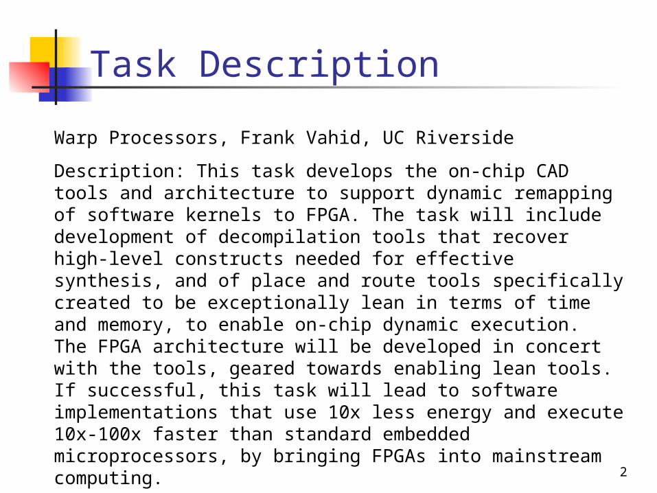
Task Description
Warp Processors, Frank Vahid, UC Riverside
Description: This task develops the on-chip CAD tools and architecture to support dynamic remapping of software kernels to FPGA. The task will include development of decompilation tools that recover high-level constructs needed for effective synthesis, and of place and route tools specifically created to be exceptionally lean in terms of time and memory, to enable on-chip dynamic execution. The FPGA architecture will be developed in concert with the tools, geared towards enabling lean tools. If successful, this task will lead to software implementations that use 10x less energy and execute 10x-100x faster than standard embedded microprocessors, by bringing FPGAs into mainstream computing.
3
µPI$
D$
Warp Config. Logic
Architecture
Profiler
Dynamic Part.
Module (DPM)
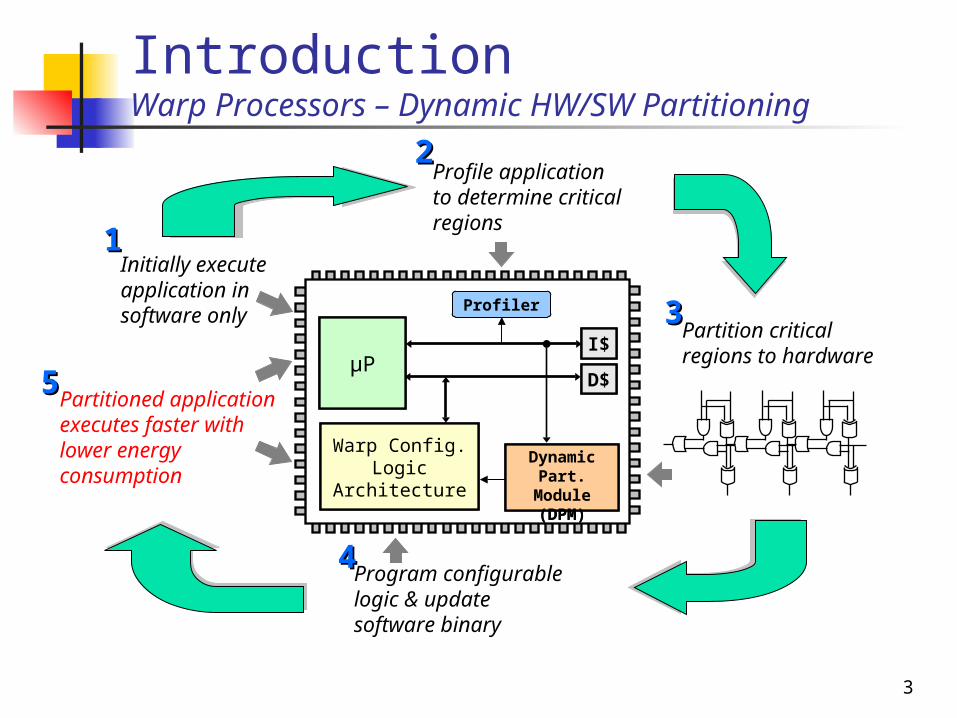
Partitioned application executes faster with lower energy consumption
55
IntroductionWarp Processors – Dynamic HW/SW Partitioning
Profile application to determine critical regions
22
Profiler
Initially execute application in software only
11
µPI$
D$
Partition critical regions to hardware
33
Dynamic Part.
Module (DPM)
Program configurable logic & update software binary
44
Warp Config. Logic
Architecture

6
IntroductionHardware/Software Partitioning
SW__________________
SW__________________
SW__________________
HW__________________
SW__________________
SW__________________
ProcessorProcessor ProcessorASIC/FPGA
Critical Regions
ProfilerProfiler Benefits Speedups of 2X to 10X
typical Speedups of 800X
possible Far more potential than
dynamic SW optimizations (1.3X)
Energy reductions of 25% to 95% typical
But can hw/sw partitioning be done dynamically?
Time Energy
SW OnlyHW/ SW
Time Energy
SW Only
ProcessorProcessor
Commonly one chip today

7
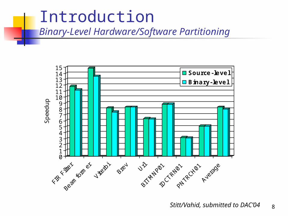
IntroductionBinary-Level Hardware/Software Partitioning
Can hw/sw partitioning be done dynamically?
Enabler – binary-level partitioning
[Stitt & Vahid, ICCAD’02] Partition starting from SW binary Can be desktop based
Advantages Any compiler, any language,
multiple sources, assembly/object support, legacy code support
Disadvantage Loses high-level information
Quality loss?
BinarySW
ProfilingStandard Compiler
BinaryBinary
BinaryPartitioner
NetlistNetlistModified Binary
ProcessorProcessor ProcessorASIC/FPGA
Traditionalpartitioningdone here
8
0123456789
101112131415
Spee
dup
Source-level
Binary-level
IntroductionBinary-Level Hardware/Software Partitioning
Stitt/Vahid, submitted to DAC’04

9
IntroductionBinary Partitioning Enables Dynamic Partitioning
Dynamic HW/SW Partitioning Embed partitioning CAD tools on-chip Feasible in era of billion-transistor chips
Advantages No special desktop tools Completely transparent Avoid complexities of supporting
different FPGA types Complements other approaches
Desktop CAD best from purely technical perspective
Dynamic opens additional market segments (i.e., all software developers) that otherwise might not use desktop CAD
BinarySW
ProfilingStandard Compiler
BinaryBinary
CAD
FPGAProc.
10
uPI$
D$
Config. Logic Arch.
Profiler
DPM
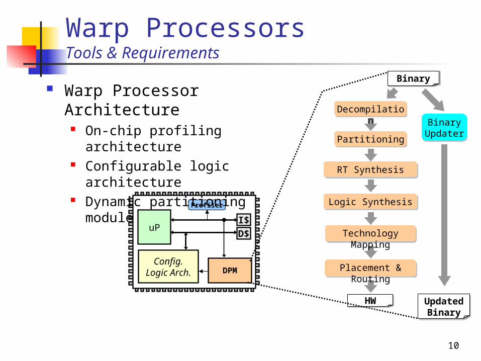
Warp ProcessorsTools & Requirements
Warp Processor Architecture
On-chip profiling architecture
Configurable logic architecture
Dynamic partitioning module
BinaryBinary
Partitioning
BinaryHW
RT Synthesis
Technology Mapping
Placement & Routing
Logic Synthesis
Decompilation
Binary Updater
BinaryUpdated Binary
11
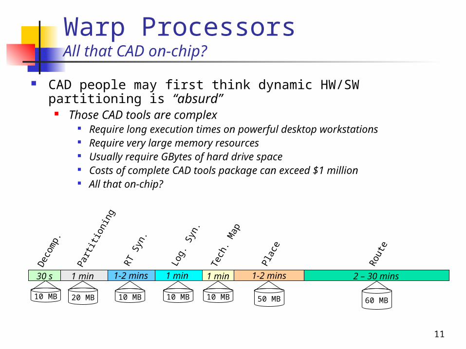
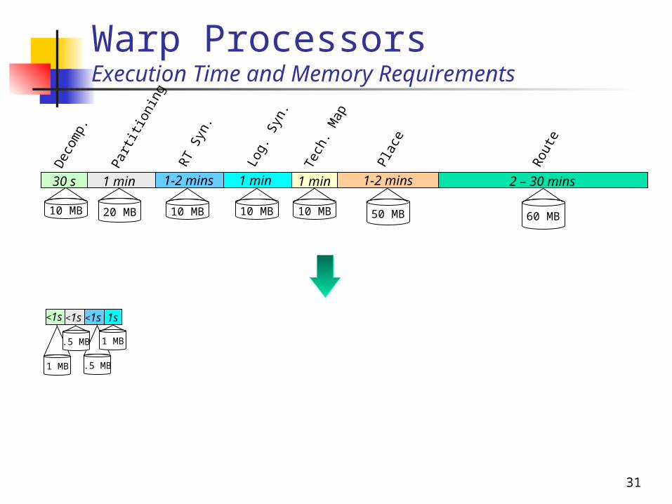
Warp ProcessorsAll that CAD on-chip?
CAD people may first think dynamic HW/SW partitioning is “absurd”
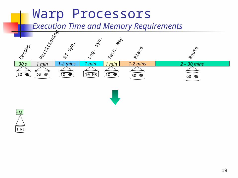
Those CAD tools are complex Require long execution times on powerful desktop workstations Require very large memory resources Usually require GBytes of hard drive space Costs of complete CAD tools package can exceed $1 million All that on-chip?
50 MB 60 MB10 MB
1 min
Log.
Syn
.
1 min
Tech
. Map
1-2 mins Pl
ace
2 – 30 mins
Rou
te
1-2 mins
RT
Syn.
10 MB
30 s
Dec
omp.
1 min
Part
itio
ning
20 MB 10 MB 10 MB
12
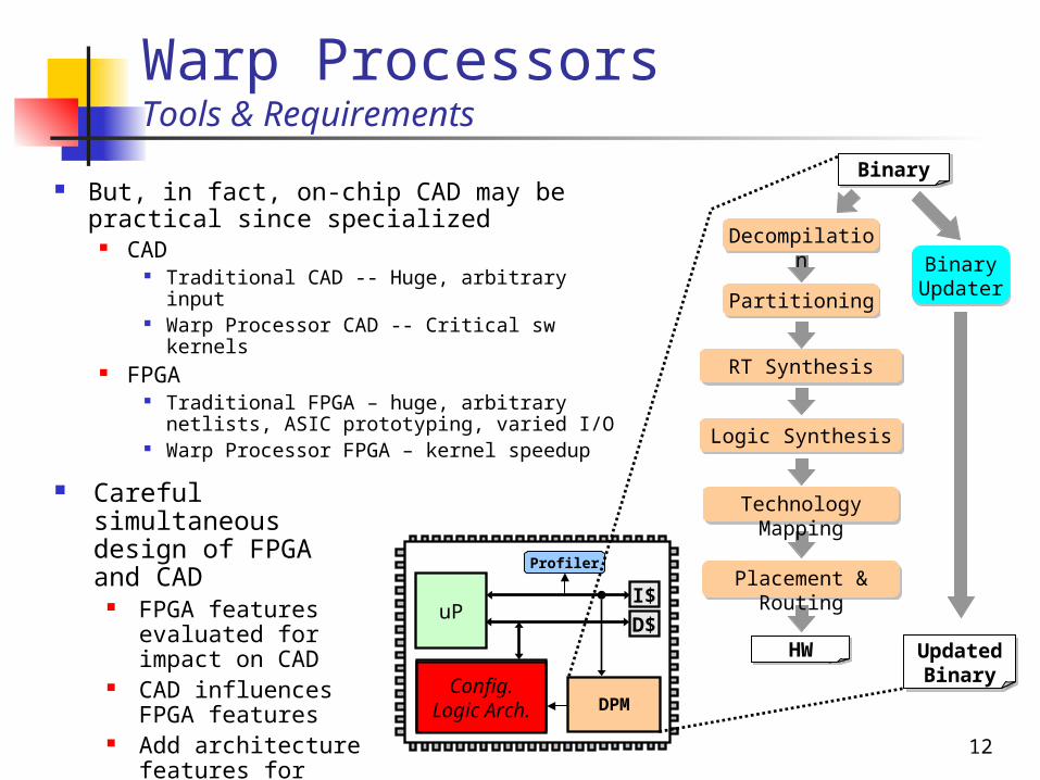
Warp ProcessorsTools & Requirements
But, in fact, on-chip CAD may be practical since specialized
CAD Traditional CAD -- Huge, arbitrary input Warp Processor CAD -- Critical sw
kernels FPGA
Traditional FPGA – huge, arbitrary netlists, ASIC prototyping, varied I/O
Warp Processor FPGA – kernel speedup
uPI$
D$
Config. Logic Arch.
Profiler
DPM
BinaryBinary
Partitioning
BinaryHW
RT Synthesis
Technology Mapping
Placement & Routing
Logic Synthesis
Decompilation
Binary Updater
BinaryUpdated Binary
Careful simultaneous design of FPGA and CAD
FPGA features evaluated for impact on CAD
CAD influences FPGA features
Add architecture features for kernels
Config. Logic Arch.

13
Warp ProcessorsConfigurable Logic Architecture
Loop support hardware Data address generators (DADG) and loop control
hardware (LCH), found in digital signal processors – fast loop execution
Supports memory accesses with regular access pattern Synthesis of FSM not required for many critical loops
32-bit fast Multiply-Accumulate (MAC) unitDADG &
LCH
Configurable Logic Fabric
Reg0
32-bit MAC
Reg1 Reg2
uPI$
D$
Config. Logic Arch.
Profiler
DPM
Lysecky/Vahid, DATE’04
14
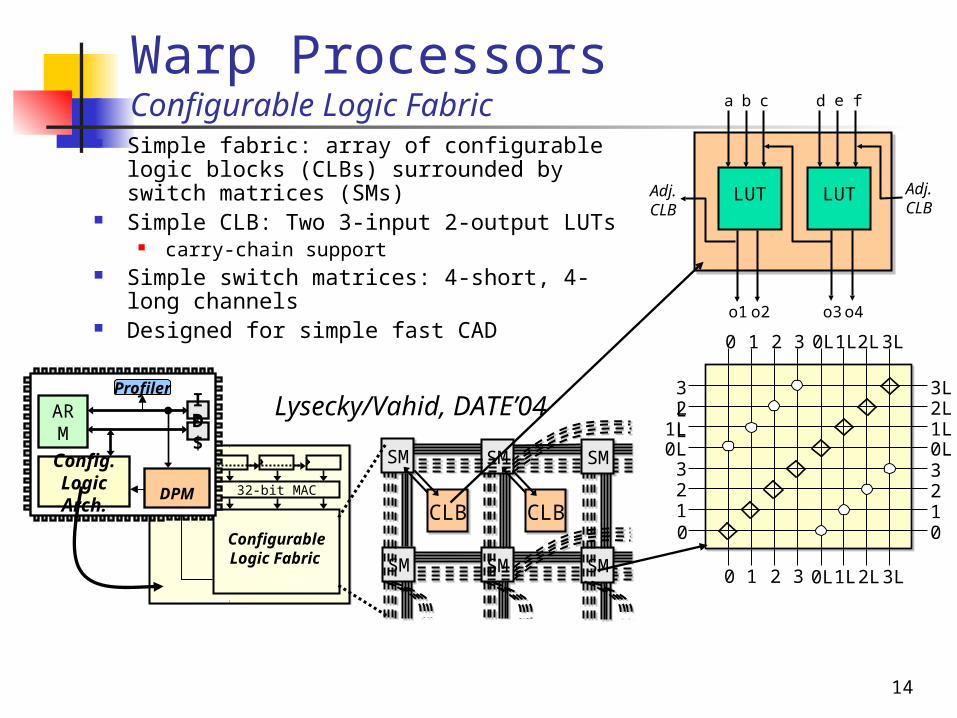
Warp ProcessorsConfigurable Logic Fabric
DADGLCH
Configurable Logic Fabric
32-bit MAC
SM
CLB
SM
SM
SM
SM
SM
CLB
SM
CLB
SM
SM
SM
SM
SM
CLB
Simple fabric: array of configurable logic blocks (CLBs) surrounded by switch matrices (SMs)
Simple CLB: Two 3-input 2-output LUTs carry-chain support
Simple switch matrices: 4-short, 4-long channels
Designed for simple fast CAD
Lysecky/Vahid, DATE’04ARM
I$D$
Config. Logic Arch.
Profiler
DPM
LUTLUT
a b c d e f
o1 o2 o3o4
Adj.CLB
Adj.CLB
0
0L
1
1L2L
2
3L
3
0123
0L1L2L
3L
0123
0L1L2L3L
0 1 2 3 0L1L2L3L

16
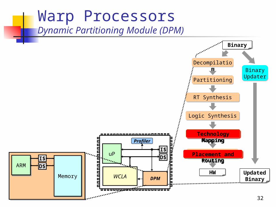
Warp ProcessorsDynamic Partitioning Module (DPM)
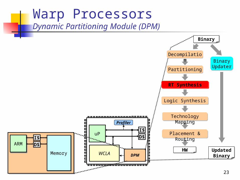
Dynamic Partitioning Module Executes on-chip partitioning tools Consists of small low-power
processor (ARM7) Current SoCs can have dozens
On-chip instruction & data caches Memory: a few megabytes
uPI$
D$
WCLA
Profiler
DPM
ARMARMI$
D$
MemoryMemory
BinaryBinary
Partitioning
BinaryHW
RT Synthesis
Technology Mapping
Placement & Routing
Logic Synthesis
Decompilation
Binary Updater
BinaryUpdated Binary
Decompilation
17
Annotated CDFG
Alias Analysis
Undoing Back-End Compiler Optimizations
Removing Instruction-Set Overhead
Control Structure Recovery
CDFG Creation
Binary Parsing
Software Binary
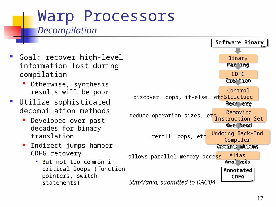
Warp ProcessorsDecompilation
Goal: recover high-level information lost during compilation
Otherwise, synthesis results will be poor
Utilize sophisticated decompilation methods
Developed over past decades for binary translation
Indirect jumps hamper CDFG recovery
But not too common in critical loops (function pointers, switch statements)
Binary Parsing
Software Binary
CDFG Creation
Control Structure Recovery
Undoing Back-End Compiler Optimizations
Alias Analysis
Annotated CDFG
Removing Instruction-Set Overhead
Stitt/Vahid, submitted to DAC’04
discover loops, if-else, etc.
reduce operation sizes, etc.
reroll loops, etc.
allows parallel memory access
18
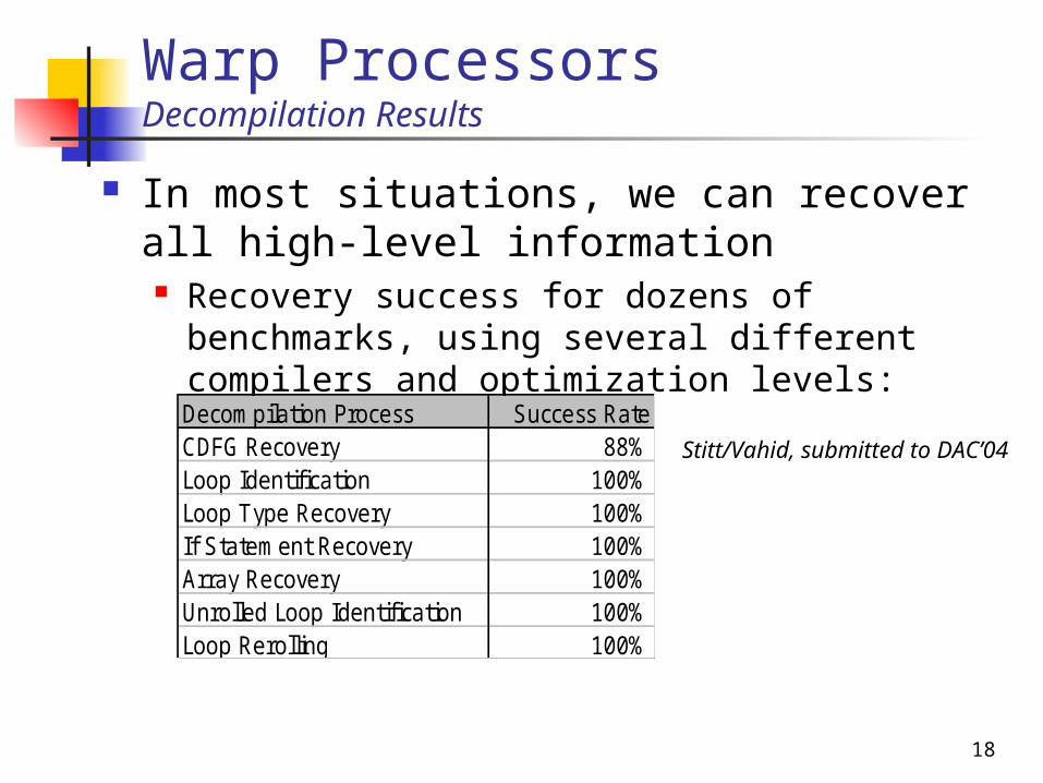
In most situations, we can recover all high-level information Recovery success for dozens of benchmarks,
using several different compilers and optimization levels: Decompilation Process Success RateCDFG Recovery 88%Loop Identification 100%Loop Type Recovery 100%If Statement Recovery 100%Array Recovery 100%Unrolled Loop Identification 100%Loop Rerolling 100%
Stitt/Vahid, submitted to DAC’04
Warp ProcessorsDecompilation Results
19
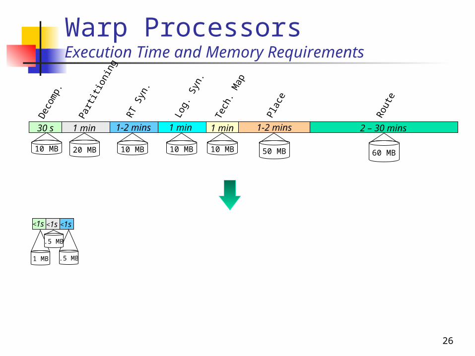
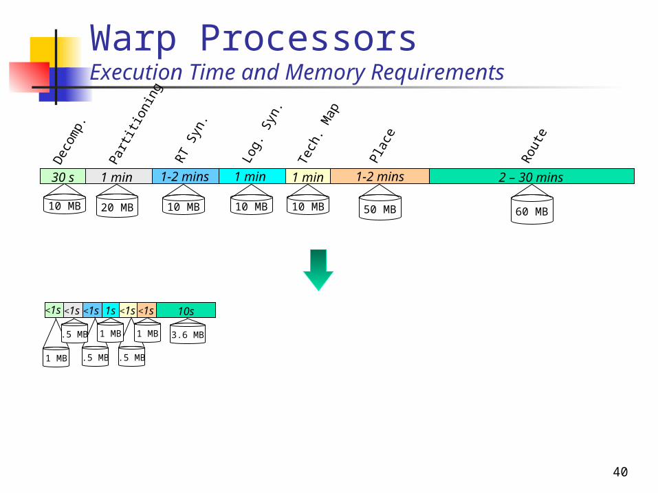
Warp ProcessorsExecution Time and Memory Requirements
<1s
1 MB
50 MB 60 MB10 MB
1 min
Log.
Syn
.
1 min
Tech
. Map
1-2 mins
Plac
e
2 – 30 mins
Rou
te
1-2 minsRT
Syn.
10 MB
30 s
Dec
omp.
1 min
Part
itio
ning
20 MB 10 MB 10 MB
23
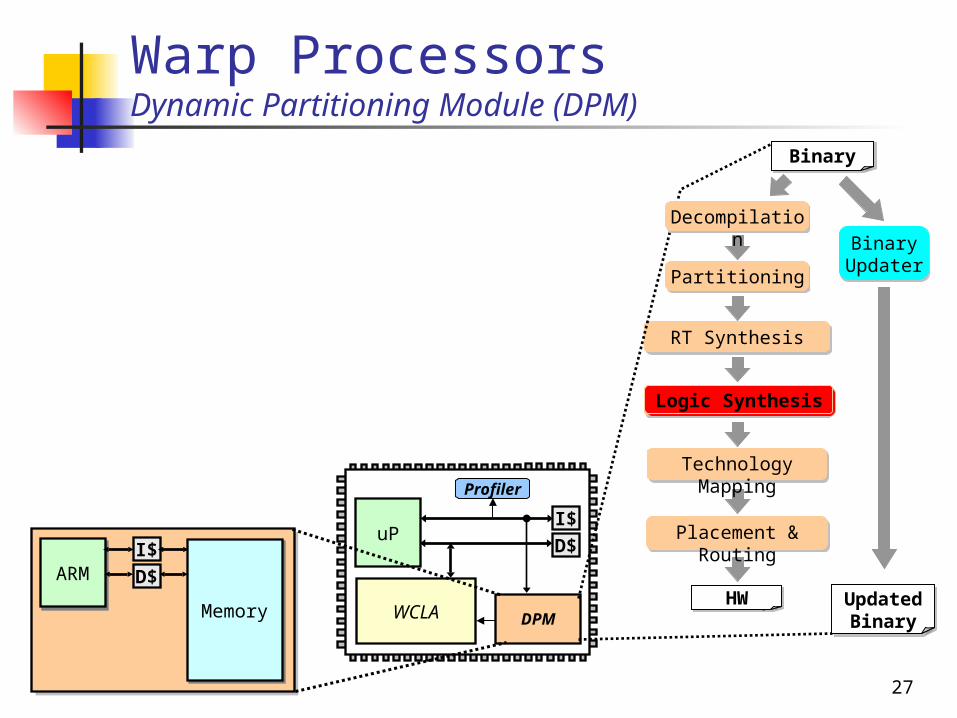
Warp ProcessorsDynamic Partitioning Module (DPM)
uPI$
D$
WCLA
Profiler
DPM
ARMARMI$
D$
MemoryMemory
BinaryBinary
Partitioning
BinaryHW
RT Synthesis
Technology Mapping
Placement & Routing
Logic Synthesis
Decompilation
Binary Updater
BinaryUpdated Binary
RT Synthesis
24
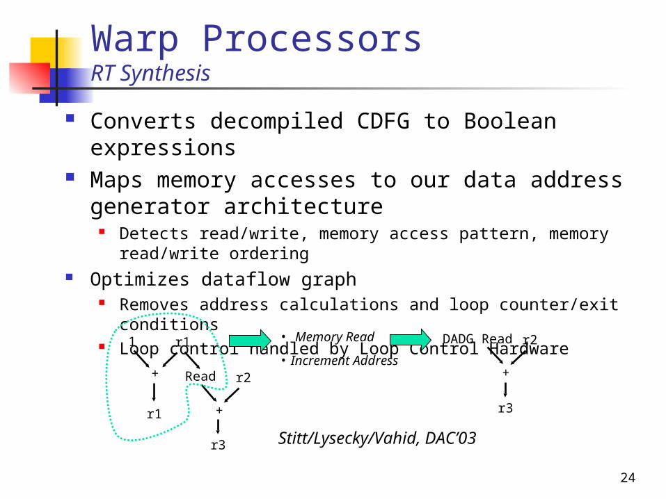
Warp ProcessorsRT Synthesis
Converts decompiled CDFG to Boolean expressions
Maps memory accesses to our data address generator architecture
Detects read/write, memory access pattern, memory read/write ordering
Optimizes dataflow graph Removes address calculations and loop counter/exit
conditions Loop control handled by Loop Control Hardware1 r1
+ Read
r1 +
r2
• Memory Read
• Increment Address
r3
DADG Read
+
r2
r3
Stitt/Lysecky/Vahid, DAC’03
25
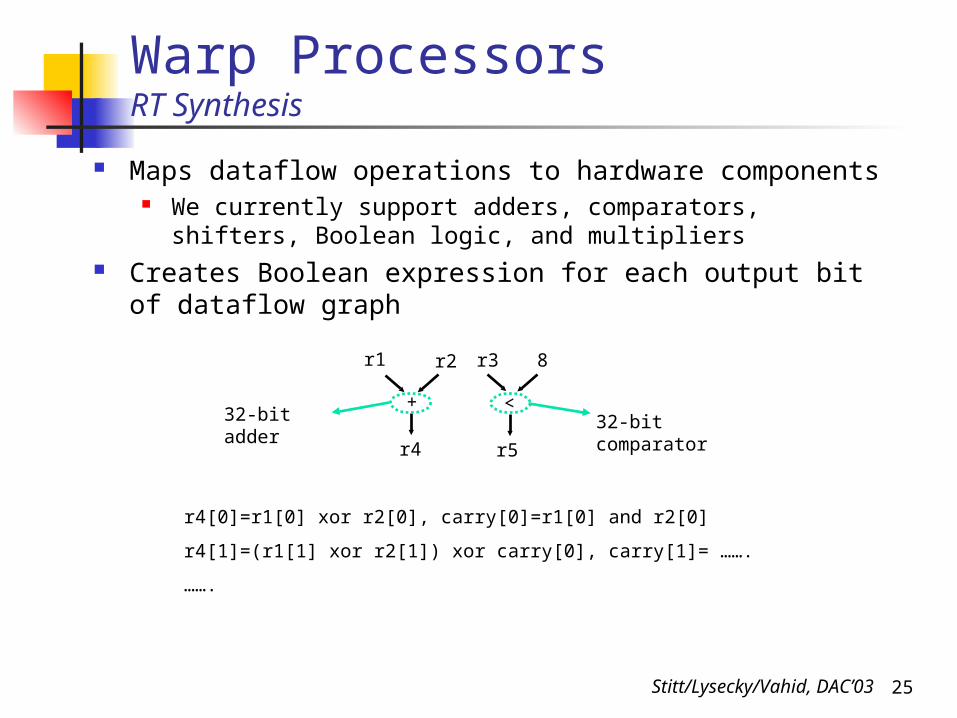
Warp ProcessorsRT Synthesis
Maps dataflow operations to hardware components We currently support adders, comparators, shifters, Boolean
logic, and multipliers Creates Boolean expression for each output bit of
dataflow graph
r4[0]=r1[0] xor r2[0], carry[0]=r1[0] and r2[0]
r4[1]=(r1[1] xor r2[1]) xor carry[0], carry[1]= …….
…….
r1 r2
+
r4
r3 8
<
r5
32-bit adder 32-bit comparator
Stitt/Lysecky/Vahid, DAC’03
26
<1s
.5 MB
Warp ProcessorsExecution Time and Memory Requirements
<1s
1 MB
<1s
.5 MB
50 MB 60 MB10 MB
1 min
Log.
Syn
.
1 min
Tech
. Map
1-2 mins
Plac
e
2 – 30 mins
Rou
te
1-2 minsRT
Syn.
10 MB
30 s
Dec
omp.
1 min
Part
itio
ning
20 MB 10 MB 10 MB
27
Warp ProcessorsDynamic Partitioning Module (DPM)
uPI$
D$
WCLA
Profiler
DPM
ARMARMI$
D$
MemoryMemory
BinaryBinary
Partitioning
BinaryHW
RT Synthesis
Technology Mapping
Placement & Routing
Logic Synthesis
Decompilation
Binary Updater
BinaryUpdated Binary
Logic Synthesis
28
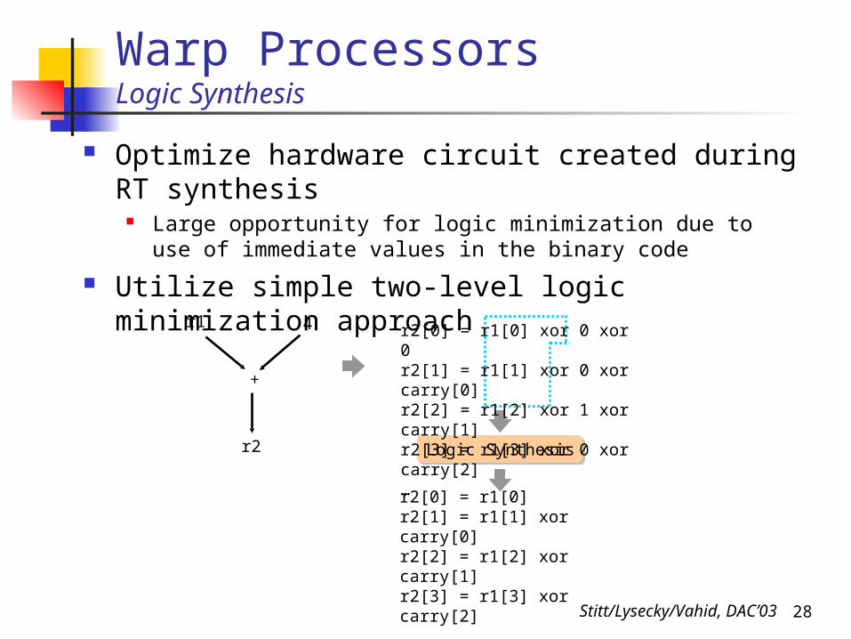
Warp ProcessorsLogic Synthesis
Optimize hardware circuit created during RT synthesis
Large opportunity for logic minimization due to use of immediate values in the binary code
Utilize simple two-level logic minimization approach r1 4
+
r2
r2[0] = r1[0]r2[1] = r1[1] xor carry[0]r2[2] = r1[2] xor carry[1]r2[3] = r1[3] xor carry[2]…
Logic Synthesis
r2[0] = r1[0] xor 0 xor 0r2[1] = r1[1] xor 0 xor carry[0]r2[2] = r1[2] xor 1 xor carry[1]r2[3] = r1[3] xor 0 xor carry[2]…
Stitt/Lysecky/Vahid, DAC’03
29
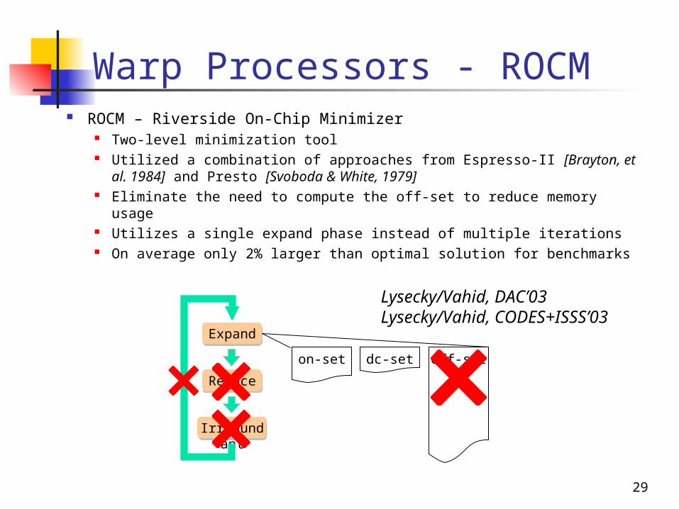
Warp Processors - ROCM ROCM – Riverside On-Chip Minimizer
Two-level minimization tool Utilized a combination of approaches from Espresso-II [Brayton, et
al. 1984] and Presto [Svoboda & White, 1979] Eliminate the need to compute the off-set to reduce memory usage Utilizes a single expand phase instead of multiple iterations On average only 2% larger than optimal solution for benchmarks
Expand
Reduce
Irredundant
dc-seton-set off-set
Lysecky/Vahid, DAC’03Lysecky/Vahid, CODES+ISSS’03

30
Warp Processors - ROCMResults
0
2
4
6
8
10
12
14
Exec. Time(seconds)
Espresso-ExactEspresso-IIROCMROCM (ARM7)
500 MHz Sun Ultra60
40 MHz ARM 7
(Triscend A7)
0
50
100
150
200
250
Code Mem(KB)
0
500
1000
1500
2000
2500
3000
3500
Data Mem (KB)
ROCM executing on 40MHz ARM7 requires less than 1 secondSmall code size of only 22 kilobytesAverage data memory usage of only 1 megabyte
Lysecky/Vahid, DAC’03Lysecky/Vahid, CODES+ISSS’03
31
<1s
.5 MB
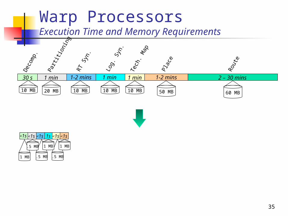
Warp ProcessorsExecution Time and Memory Requirements
1s
1 MB
<1s
1 MB
<1s
.5 MB
50 MB 60 MB10 MB
1 min
Log.
Syn
.
1 min
Tech
. Map
1-2 mins
Plac
e
2 – 30 mins
Rou
te
1-2 minsRT
Syn.
10 MB
30 s
Dec
omp.
1 min
Part
itio
ning
20 MB 10 MB 10 MB
32
Warp ProcessorsDynamic Partitioning Module (DPM)
uPI$
D$
WCLA
Profiler
DPM
ARMARMI$
D$
MemoryMemory
BinaryBinary
Partitioning
BinaryHW
RT Synthesis
Technology Mapping
Placement & Routing
Logic Synthesis
Decompilation
Binary Updater
BinaryUpdated Binary
Technology Mapping
Placement and Routing
33
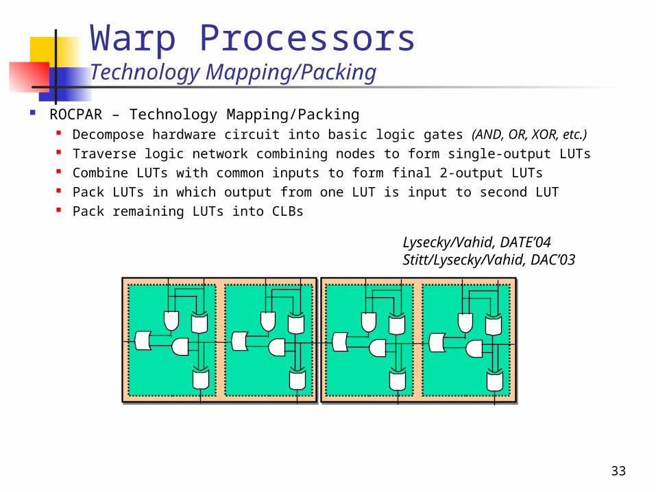
Warp ProcessorsTechnology Mapping/Packing
ROCPAR – Technology Mapping/Packing Decompose hardware circuit into basic logic gates (AND, OR, XOR,
etc.) Traverse logic network combining nodes to form single-output LUTs Combine LUTs with common inputs to form final 2-output LUTs Pack LUTs in which output from one LUT is input to second LUT Pack remaining LUTs into CLBs Lysecky/Vahid, DATE’04
Stitt/Lysecky/Vahid, DAC’03

34
Warp ProcessorsPlacement
ROCPAR – Placement Identify critical path, placing critical nodes in center of configurable
logic fabric Use dependencies between remaining CLBs to determine placement
Attempt to use adjacent cell routing whenever possible
CLB CLB CLB CLB
CLB CLB CLB CLB
CLB CLB CLB CLB
CLB CLB CLB CLB
CLB CLB
CLB
Lysecky/Vahid, DATE’04Stitt/Lysecky/Vahid, DAC’03
35
<1s
.5 MB
<1s
.5 MB
Warp ProcessorsExecution Time and Memory Requirements
1s
1 MB
<1s
1 MB
<1s
1 MB
<1s
.5 MB
50 MB 60 MB10 MB
1 min
Log.
Syn
.
1 min
Tech
. Map
1-2 mins
Plac
e
2 – 30 mins
Rou
te
1-2 minsRT
Syn.
10 MB
30 s
Dec
omp.
1 min
Part
itio
ning
20 MB 10 MB 10 MB
36
Warp ProcessorsRouting
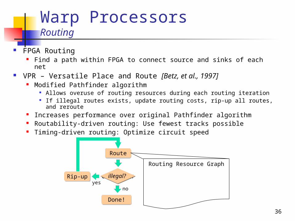
FPGA Routing Find a path within FPGA to connect source and sinks of each net
VPR – Versatile Place and Route [Betz, et al., 1997] Modified Pathfinder algorithm
Allows overuse of routing resources during each routing iteration If illegal routes exists, update routing costs, rip-up all routes, and
reroute Increases performance over original Pathfinder algorithm Routability-driven routing: Use fewest tracks possible Timing-driven routing: Optimize circuit speed
Route
Rip-up
Done!
congestion?illegal?
noyes
Routing Resource Graph
37
Warp Processors Routing
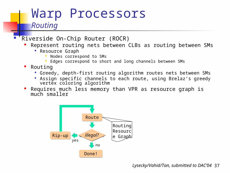
Riverside On-Chip Router (ROCR) Represent routing nets between CLBs as routing between SMs
Resource Graph Nodes correspond to SMs Edges correspond to short and long channels between SMs
Routing Greedy, depth-first routing algorithm routes nets between SMs Assign specific channels to each route, using Brelaz’s greedy
vertex coloring algorithm Requires much less memory than VPR as resource graph is
much smaller
Routing Resource GraphRouting Resource Graph
Route
Rip-up
Done!
congestion? illegal?
noyes
Lysecky/Vahid/Tan, submitted to DAC’04
38
Warp Processors Routing: Performance and Memory Usage Results
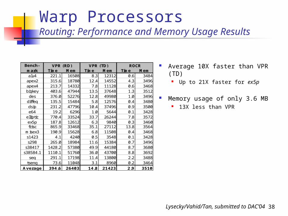
Time Mem Time Mem Time Memalu4 221.1 16508 8.3 12312 0.6 3484
apex2 315.6 18780 12.4 14552 4.3 3496apex4 213.7 14332 7.8 11128 0.6 3468bigkey 403.6 47944 13.5 37648 1.3 3512des 376.0 52276 12.8 49980 1.0 3496
diffeq 135.5 15484 5.8 12576 0.4 3480dsip 231.2 47796 10.4 37496 0.9 3500e64 19.2 6296 1.0 5644 0.1 3428
elliptic 770.4 33524 33.7 26244 7.8 3572ex5p 187.8 12612 6.3 9840 0.3 3460frisc 865.9 33468 35.1 27112 13.8 3564
misex3 190.9 15628 6.8 11508 0.4 3468s1423 4.1 4240 0.5 3548 0.1 3428s298 265.0 18984 11.6 15384 0.7 3496
s38417 1428.2 57380 49.9 44180 8.7 3680s38584.1 1110.1 51760 36.0 43700 8.8 3692
seq 291.1 17198 11.4 13800 2.2 3488tseng 73.6 11048 3.1 8960 0.2 3464
Average 394.6 26403 14.8 21423 2.9 3510
VPR (TD) ROCRBench-mark
VPR (RD) Average 10X faster than VPR (TD) Up to 21X faster for ex5p
Memory usage of only 3.6 MB 13X less than VPR
Lysecky/Vahid/Tan, submitted to DAC’04
39
Warp ProcessorsRouting: Critical Path Results
0
25
50
75
100
125
150
Benchmark
Crt
ica
l pa
th (
ns
)
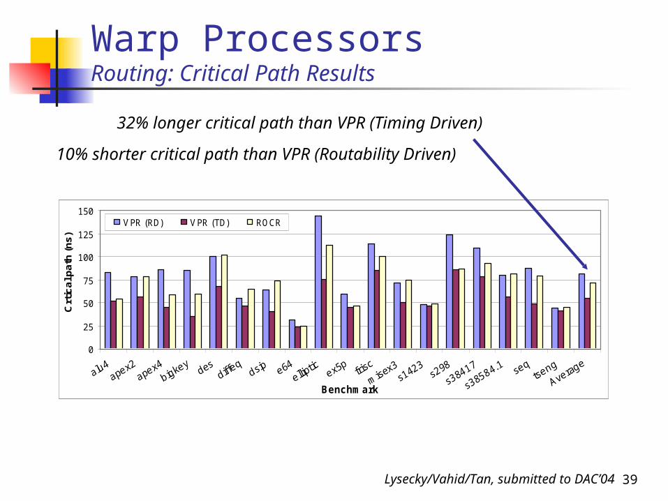
VPR (RD) VPR (TD) ROCR
10% shorter critical path than VPR (Routability Driven)
32% longer critical path than VPR (Timing Driven)
Lysecky/Vahid/Tan, submitted to DAC’04
40
<1s
.5 MB
<1s
.5 MB
Warp ProcessorsExecution Time and Memory Requirements
1s
1 MB
<1s
1 MB
10s
3.6 MB
<1s
1 MB
<1s
.5 MB
50 MB 60 MB10 MB
1 min
Log.
Syn
.
1 min
Tech
. Map
1-2 mins
Plac
e
2 – 30 mins
Rou
te
1-2 minsRT
Syn.
10 MB
30 s
Dec
omp.
1 min
Part
itio
ning
20 MB 10 MB 10 MB

43
Initial Overall Results Experimental Setup
Considered 12 embedded benchmarks from NetBench, MediaBench, EEMBC, and Powerstone
Average of 53% of total software execution time was spent executing single critical loop (more speedup possible if more loops considered)
On average, critical loops comprised only 1% of total program size
brev 992 104 70.0% 10.5% 3.3g3fax1 1094 6 31.4% 0.5% 1.5g3fax2 1094 6 31.2% 0.5% 1.5
url 13526 17 79.9% 0.1% 5logmin 8968 38 63.8% 0.4% 2.8pktflow 15582 5 35.5% 0.0% 1.6canrdr 15640 5 35.0% 0.0% 1.5bitmnp 17400 165 53.7% 0.9% 2.2tblook 15668 11 76.0% 0.1% 4.2ttsprk 16558 11 59.3% 0.1% 2.5
matrix01 16694 22 40.6% 0.1% 1.7idctrn01 17106 13 62.2% 0.1% 2.6
Average: 53.2% 1.1% 3.0
Speedup BoundLoop
InstructionsBenchmark
Total Instructions
Loop Execution Time
Loop Size%
44
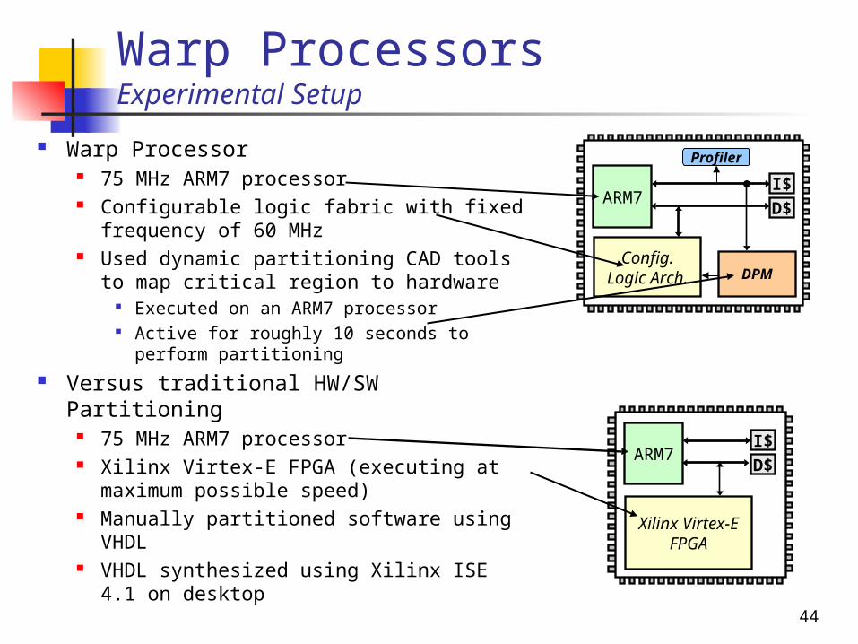
Warp ProcessorsExperimental Setup
Warp Processor 75 MHz ARM7 processor Configurable logic fabric with fixed
frequency of 60 MHz Used dynamic partitioning CAD tools to
map critical region to hardware Executed on an ARM7 processor Active for roughly 10 seconds to
perform partitioning Versus traditional HW/SW Partitioning
75 MHz ARM7 processor Xilinx Virtex-E FPGA (executing at
maximum possible speed) Manually partitioned software using
VHDL VHDL synthesized using Xilinx ISE 4.1
on desktop
ARM7I$
D$
Config. Logic Arch.
Profiler
DPM
ARM7I$
D$
Xilinx Virtex-E FPGA

45
0
1
2
3
4
5
Spee
dup
Warp Proc.
Xilinx Virtex-E
Warp Processors: Initial ResultsPerformance Speedup
Average speedup of 2.1vs. 2.2 for Virtex-E
4.1
46
0%
20%
40%
60%
80%
100%
Ener
gy
Red
uct
ion
Warp Proc.
Xilinx Virtex-E
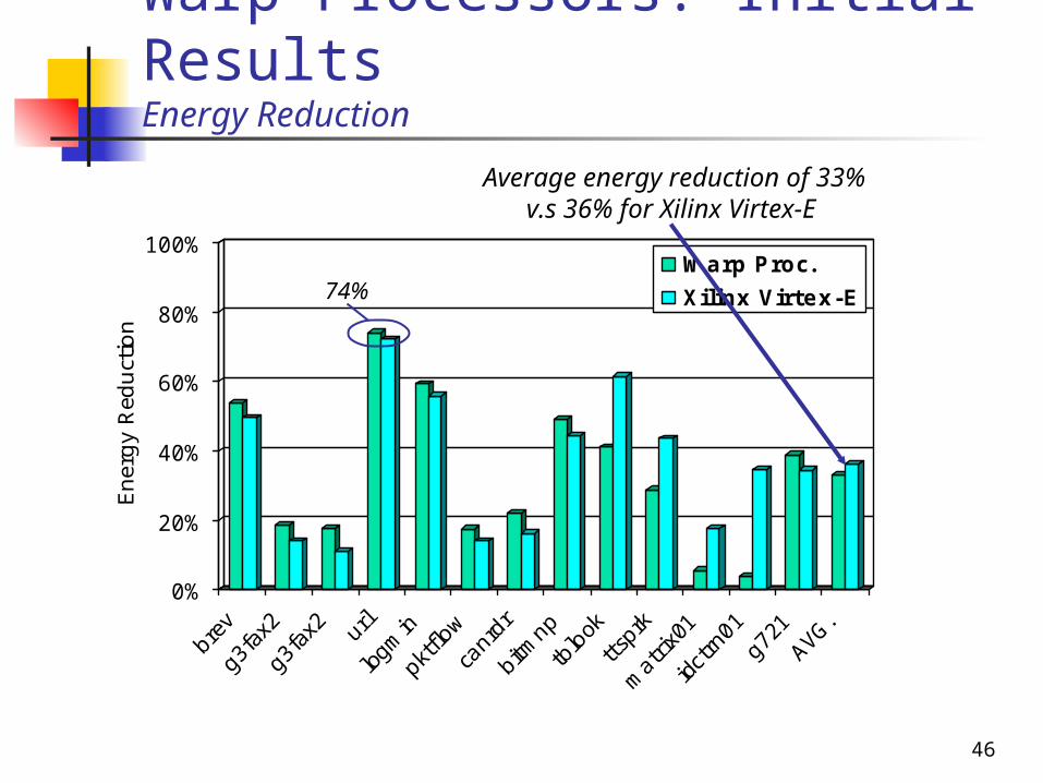
Warp Processors: Initial ResultsEnergy Reduction
Average energy reduction of 33%v.s 36% for Xilinx Virtex-E
74%
47
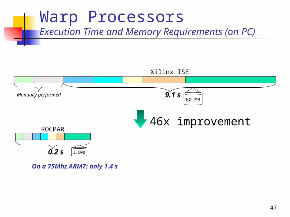
Warp Processors Execution Time and Memory Requirements (on PC)
3.6MB
60 MB9.1 s
Xilinx ISE
0.2 s
ROCPAR
On a 75Mhz ARM7: only 1.4 s
Manually performed
46x improvement
48
Current/Future Work Extending Warp Processors
Multiple software loops to hardware Handling custom sequential logic Better synthesis, placement, routing
JIT FPGA Compilation Idea: standard binary for FPGA
Similar benefits as standard binary for microprocessor
e.g., portability, transparency, standard tools
49
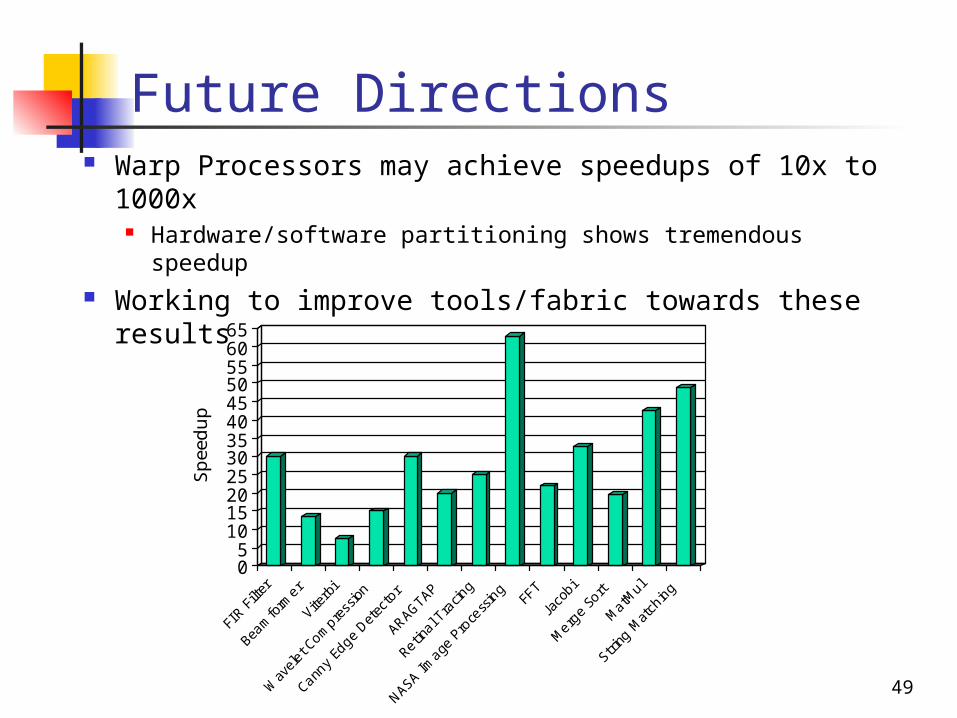
Future Directions Warp Processors may achieve speedups of 10x to
1000x Hardware/software partitioning shows tremendous speedup
Working to improve tools/fabric towards these results
05
101520253035404550556065
Spee
dup
50
Publications A Configurable Logic Architecture for Dynamic Hardware/Software
Partitioning, R. Lysecky and F. Vahid, Design Automation and Test in Europe Conference (DATE), February 2004.
Frequent Loop Detection Using Efficient Non-Intrusive On-Chip Hardware, A. Gordon-Ross and F. Vahid, ACM/IEEE Conf. on Compilers, Architecture and Synthesis for Embedded Systems (CASES), 2003; to appear in special issue “Best of CASES/MICRO” of IEEE Trans. on Comp.
A Codesigned On-Chip Logic Minimizer, R. Lysecky and F. Vahid, ACM/IEEE ISSS/CODES conference, 2003.
Dynamic Hardware/Software Partitioning: A First Approach. G. Stitt, R. Lysecky and F. Vahid, Design Automation Conference, 2003.
On-Chip Logic Minimization, R. Lysecky and F. Vahid, Design Automation Conference, 2003.
The Energy Advantages of Microprocessor Platforms with On-Chip Configurable Logic, G. Stitt and F. Vahid, IEEE Design and Test of Computers, November/December 2002.
Hardware/Software Partitioning of Software Binaries, G. Stitt and F. Vahid, IEEE/ACM International Conference on Computer Aided Design, November
2002.


![[IJCT-V1I2P2] Author :Vahid Ghoreish](https://img.dokumen.tips/doc/110x75/577cc1761a28aba7119326b7/ijct-v1i2p2-author-vahid-ghoreish.jpg)