Embed Size (px)
Citation preview

1086 1430September 1995
WarningThis equipment must be installed andused in accordance with themanufacturer's recommendations.Installation must be performed byproperly trained and authorisedpersonnel.
Failure to follow these instructions mayinvalidate your warranty and/or impairthe safe functioning of your equipment.
Please contact your local Wallacrepresentative for installation.
WALLAC


1414-932-02March 1996
INSTRUMENT MANUAL
1414 WinSpectralTM
Digital Spectrum Analysis (DSA) based liquidscintillation counter
For instruments with software version 1.3including WinSpectral aJfi and Guardian
WAIIACAN ^EGzG COMPANY
Wallac Oy, P.O. Box 10, FIN-20101 Turku, Finland. Tel: +358-21-2678111 Telex 62333 wac fin, Telefax: +358- 21-2678 357


Contents
Contents1 IntroductionIntroduction l-lHardware features and benefits I-2Software features and benefits I-7
2 User manual
3 Calculation methods
4 Quality control informationWarning regarding installation and warrantyQC contents
5 Installation informationInstallation 5-1MultiCalc installation 5-7Installation report for Wallac 1414 WinSpectralInstallation report appendix
6 Specifications, Safety and Routine maintenance6.1 Specifications 6-16.2 Safety and radioactive materials 6-36.3 Routine maintenance 6-5
7 Spare parts information
8 Index


TrademarksWinSpectral, FlexiRack, DOT-DPM, Poslden, ChemiStrip and MultiCalc are trademarks of Wallac Oy
Lotus 123 and Symphony are registered trademarks of Lotus Development Corporation
MS-DOS, Microsoft, Windows and Excel are registered trademarks of Microsoft Corporation
Pentium is a registered trademark of Intel Corporation


1 Introduction


Introduction
IntroductionA new LS counterThe Wallac 1414 range of DSA liquid scintillationcounters, WinSpectral, WinSpectral oc/f$ and Guardian,is created to bring the very latest in LSC and PC tech-nology to your laboratory. The combination of DigitalSpectrum Analysis (DSA) with the Microsoft Win-dows graphical user interface as well a/p separation(WinSpectral a/|3 and Guardian) and sophisticatedshielding (Guardian) makes an unbeatable combina-tion.
In this manual you will find a description of what youcan do with your counter (whichever model you have),including the various options available, an explanationof how to use the instrument, as well as backgroundinformation about how it works and how to install it.
Note: in this manual the name WinSpectral is normallyused and no distinction is made between the three dif-ferent models except where they differ.
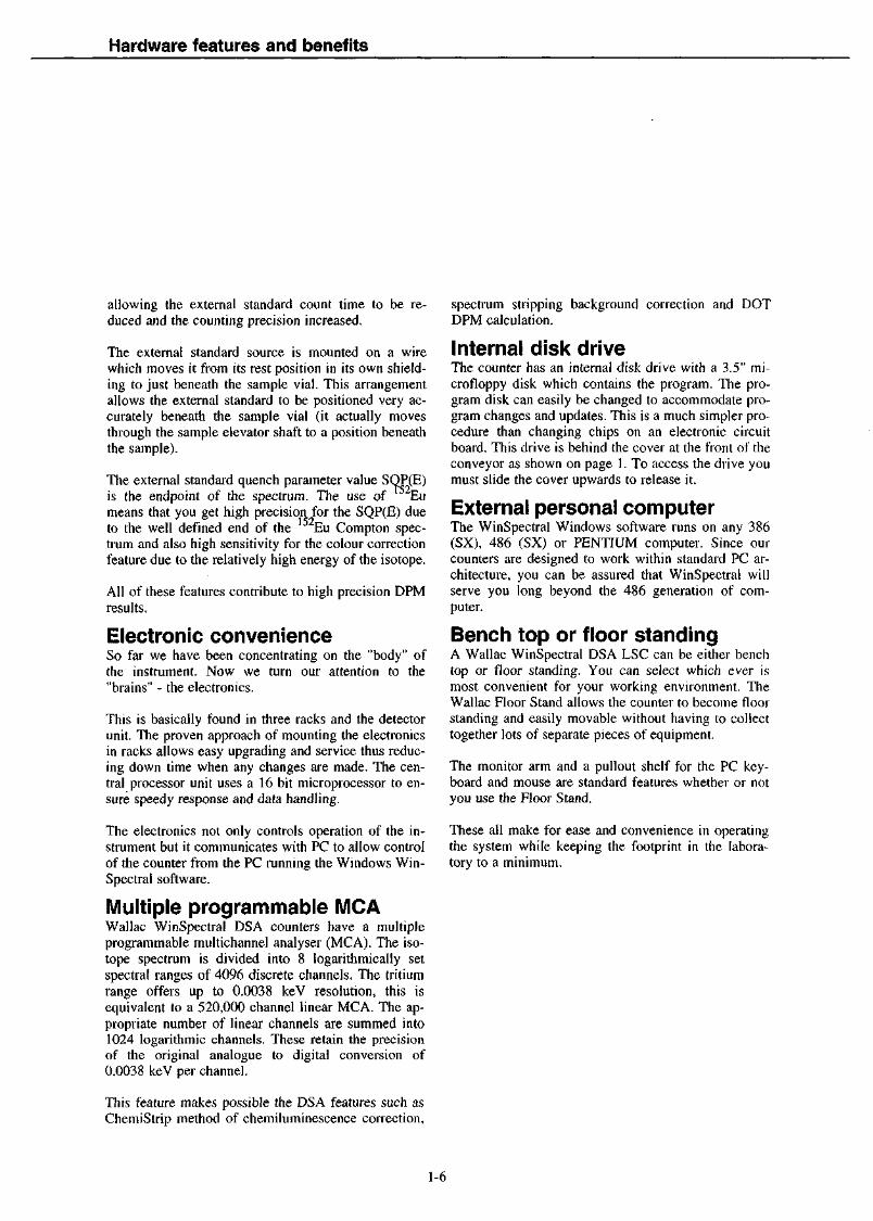
The figure below shows the instrument and identifiesthe different parts of the system.
PC display forI WinSpectralsoftware andlive results
Instrument on/offswitch and socketsfor cables to PC andraw data printer
Instrument cover.(Keep closedwhen counting)
Outputprinter
PCkeyboard
Disk drive for programdisk (behind cover)
Wallac 1414 WinSpectral and peripherals

Hardware features and benefits
Hardware features andbenefitsEleganceThe first things that comes to your attention when youlook at a Wallac 1414 WinSpectral DSA liquid scintil-lation counter are the elegant lines of the conveyorcover and the conveniently placed PC screen, key-board and mouse. These impressions of elegance andconvenience are not just superficial features of thecounter, they run through every aspect of the Win-Spectral hardware and software. These features andthe benefits they bring you are described in the follow-ing chapters.
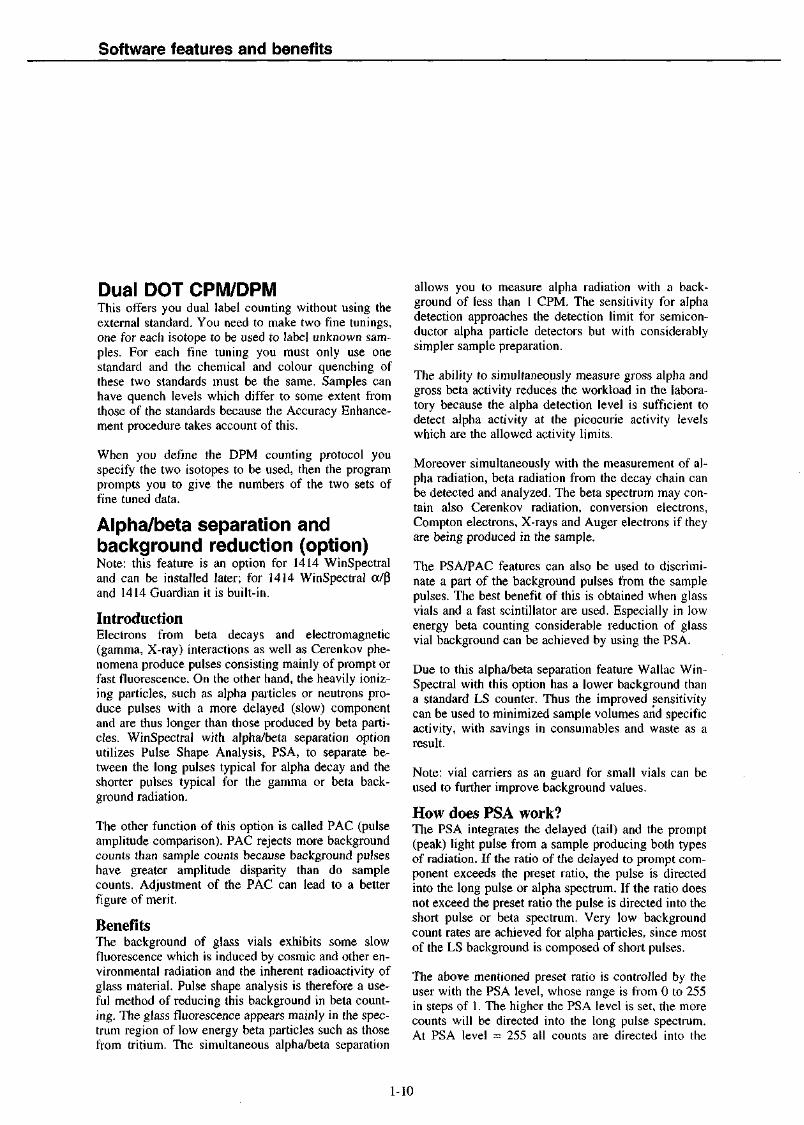
FlexiRack™ sample changerThe conveyor is designed to give the maximum visi-bility to the user. You can easily see the sample rackswherever they happen to be on the conveyor. Thecover of the conveyor is made of a plastic which bothallows a clear view of the conveyor yet shields thesamples from ultra-violet light and thus reduces theproblem of chemiluminescence. The cover is sup-ported by a spring-loaded lever so that it opens andcloses smoothly.
The sample conveyor has two lanes for sample racks,an in-stream (on the right) and an out-stream, as wellas two transfer lanes, one of which is the countinglane. Sample racks glide along the in-stream and out-stream of the conveyor, moved by friction contact withtwo rubber belts. Movement along the transfer lanes isby precision made toothed belts. The conveyor iscoated by an electrically conductive teflon layer to re-duce friction to a minimum and to prevent the genera-tion of static electricity on the sample racks. The con-veyor motors run very quietly to avoid disturbance tousers and others in the laboratory.
All movement is controlled by stepper motors and di-rectly triggered optical sensors. This removes the dan-ger of sensors jamming and increases the reliability ofthe whole conveyor system. Sample change time isabout 9 sees.
Conveyor movement is fully bi-directional. With theOneRack function counting is interrupted, the rack inthe counting position is driven backwards so that youcan load a single rack for stat counting. After this rackhas been counted, counting of the other racks resumesautomatically. You do not have to remember to put theinterrupted rack back at the head of the in-stream later
Disk drivecover
Coloureddot
Emptystoprack
Loading racks on Wallac WinSpectral
1-2

Hardware features and benefits
on because it is already in the right position to resumecounting.
Multi-size racks and vialsYou are no longer limited to using only one size ofrack on the conveyor if you have the appropriate op-tions:
With FlexiRack I you can load racks of twelve 20 mlsamples along with racks of eighteen 6 ml samples.
With FlexiRack II you can not only load racks of theabove two types but also racks of twenty-four 4 mlsamples.
These can be in any order.
A 20 ml sample rack can hold twelve samples with amaximum vial diameter of 28.4 mm. The conveyorwill accept 28 racks making a full load of 336 sam-ples.
The corresponding figures for 6 ml vials are 18.4 mmdiameter, 18 samples per rack and 40 racks on theconveyor making 720 samples in all.
For 4 ml vials the figures are 13.4 mm diameter, 24samples per rack, 52 racks per conveyor load, i.e. 1248samples.
6 ml sample rack
20 ml sample rack
Racks for different vial sizes accepted by the FlexiRack system
The maximum height allowed for the top of a vialabove the conveyor is 78 mm. This means that for a
vial of the maximum diameter in any of the categoriesits length can be up to 68 mm. Smaller vials in anycategory can be a few millimetres longer.
Not only flat bottomed vials can be accepted but alsoround bottomed and conical vials. For example adapt-ers allow Eppendorf tubes and Microfuge tubes to becounted directly without the need for carrier vials.
Users with different vial sizes can load their ownbatches of samples on the same conveyor at the sametime.
Poslden™ ID readerThe purpose of the ID system is to allow 'hands offperformance of the instrument and to enable total re-sults identification. 'Hands off means that countingprocedures such as changes of protocol, quench finetuning or stat counting, can be initiated automatically.Good laboratory practice requires that the results areidentified in data files or on printouts with ID num-bers. The Wallac WinSpectral Poslden ID reader en-ables all this.
PROTOCOL NO.
Rack number orstandardization orINTERRUPT RACK
Poslden system
Poslden uses a barcode reader and ID labels. These areself-adhesive and attach to a strip of plastic, the IDClip which is then attached to the end of the samplerack. The position of the clip is such that the codingcan be easily read without moving the rack, whereverthe rack is on the conveyor. The combination of IDlabels and clips allow each laboratory to prepare the

Hardware features and benefits
needed combination of coded ID Clips to meet its indi-vidual requirements.
The ready-to-use ID Clip can have labels on it as fol-lows:
The clip for the first rack in the assay has up to twolabels- a label with the protocol number.- an optional label with the rack number for the firstrack.
The clips for other racks in the assay need only to havethe rack No. label fixed them
If the rack contains quenched standards the ID Clip iscoded with a label showing the quench protocol num-ber (1-99) and instead of rack No. a special labelwhich identifies the samples in the rack as samples forspectrum library fine tuning.
For automatic interrupt counting the rack is coded witha clip with the protocol number and a special labelindicating the interrupt function.
The ID labels are supplied in a binder with 20 sheetsof labels. The ID Clips are supplied in a package of100. The box on the PC keyboard shelf can be used toshare the ID binder and clips.
Elevator reliabilityThe elevator system is designed to handle a whole va-riety of sample vials without the danger of the vialsfalling over or getting jammed. The key to this is thesmall sized elevator head combined with the centraliz-ing counterweight. The counterweight meets samplesbefore they are raised from the rack thus ensuring thatthey remain vertical all the time they are on the eleva-tor.
Static eliminationPlastic vials are widely used in liquid scintillationcounting and manufacturers tend to use plastic also asa rack material. Conditions are often optimum for thebuild-up of static charge, especially when relative hu-midity is low (central heating) and lab technicianshave to use plastic gloves during sample preparation(as when using conventional toluene, xylene and cu-mene based cocktails).
Static build-up on the sample vials is minimized bothby the presence of ionizers around the sample elevator
and by the fact that at no point does the vial come intocontact with any material which might tend to depositcharge on it since a vial in the FlexiRack™ system israised directly into the measuring chamber withoutmaking further contact with other materials. The rackdesign also reduces static charge build-up, because thesamples are located in round holes in the rack withoutany sharp edges which tend to collect static chargesmore easily. The light shutter is in the form of twoplates which close around the stem of the elevator af-ter the vial is in position.
There is also a Statistic Monitor which flags any sam-ples which show signs of static electricity discharges.
Automatic continuous spectrumstabilization (ACSS)
LEDA
PMT w PMT
Calibration pulse
Sample spectrum
ACSS system
You need to be sure that your instrument is stable.You do not want changes in high voltage, temperature,detectors or aging to affect the accuracy of your re-sults. The patented built-in "automatic continuousspectrum stabilization" system ACSS offers gain sta-bility for your Wallac WinSpectral counter without theneed to measure reference samples. This system iscompletely automatic and requires no user interven-tion.
The principle is to detect when a change that wouldaffect the gain of the instrument occurs and by meansof a feedback loop to correct for the change so that thegain remains stable. Each photomultiplier has a tem-perature compensated reference light emitting diode(LED) which is fixed close to each detector and isused to check the gain of the PMT, see the figureabove. A reference pulse is produced in the photomul-tiplier 10 times a second. The ratio of the pulse pro-
1-4

Hardware features and benefits
duced at the first dynode to that produced at the anodeis measured. This ratio should be constant even if theLED output changes. If the ratio changes then the gainhas changed. To compensate, the high voltage is ad-justed until the reference pulse ratio is back to what itwas. This takes care of changes to the high voltage anddetectors. A second feedback loop monitors the signalat the first dynode to ensure that the whole system istemperature stabilized.
ACSS also acts as a protection against any damage todetectors through light leaks. If a leak occurs, the volt-age to the detectors is automatically reduced thus pro-tecting them from overloading.
Multi-section passive shieldingThe massive lead shielding combined with the coinci-dence electronics for the pairs of detectors reduces thebackground to a low level. However this shieldingdoes not make for an instrument too heavy to be con-veniently handled because you can easily remove thelead shielding and then reassemble it when the instru-ment has been moved to its new position. The figurebelow shows the pieces and the order in which theyshould be removed from WinSpectral. Assembly isperformed in the opposite order. See the installationchapter for more information about shielding.
Order for removing shielding
Guardian guard detectorThe Wallac 1414 Guardian low level counter isequipped with an external guard detector around thesample chamber and phototubes. The guard has itsown phototubes and is optically isolated from the sam-ple chamber and thus offers true background event de-tection. It does not cause observable counting effi-ciency losses in low level counting. A sample eventthat is simultaneous with the guard event is rejected bythe electronics since the event is then most probably
caused by a particle or photon from the environment.No limitation in sample fluor selection is introducedby this background subtraction method.
The guard is switched on automatically, and remainson except when the external standard is being used.Usage of Wallac Guardian is thus identical to that ofWallac 1414 WinSpectral oc/p\ but the performance isimproved due to the lower background rate.
Temperature control for samplehomogeneityWhen dealing with the maximum sample holding ca-pacity of scintillators it becomes very essential that thetemperature remains practically constant through thewhole sample batch. Proper temperature control guar-antees that all samples are counted at the same tem-perature in spite of variation of ambient conditions (iffor instance the air conditioning is turned off duringthe night time). Thus the risk of phase separation insamples due to, for example, a temperature drop dur-ing overnight counting, is eliminated.
The conveyor can be temperature stabilized. This isachieved by installing the optional Temperature Con-trol unit which can be set to maintain the temperatureat a selected value in the range 5°C below ambient to10°C above. The temperature control system is basedon two thermoelectric (Peltier) modules, which en-ables users to adjust and control the temperature viasoftware.
A more powerful external cooling system (10° C be-low room temperature) can be added later if needed.
A parameter called TEMP in the programmable outputallows you to output the temperature at which samplemeasurements were made.
External standard for higherprecision DPMThe wide range of vial types accepted by Wallac Win-Spectral counters puts greater demands on the externalstandard parameters than ever before. If the count rateof the external standard depends on the sample vol-ume, the few microlitres in a Microfuge tube will givea iow count rate. To avoid this the isotope of the exter-nal standard is '' Eu, which belongs to a lower toxic-ity class than previously used external standard iso-topes, which means a higher activity can be used thus
Hardware features and benefits
allowing the external standard count time to be re-duced and the counting precision increased.
The external standard source is mounted on a wirewhich moves it from its rest position in its own shield-ing to just beneath the sample vial. This arrangementallows the external standard to be positioned very ac-curately beneath the sample vial (it actually movesthrough the sample elevator shaft to a position beneaththe sample).
The external standard quench parameter value SQP(E)is the endpoint of the spectrum. The use of " Eumeans that you get high precision for the SQP(E) dueto the well defined end of the ' Eu Compton spec-trum and also high sensitivity for the colour correctionfeature due to the relatively high energy of the isotope.
All of these features contribute to high precision DPMresults.
Electronic convenienceSo far we have been concentrating on the "body" ofthe instrument. Now we turn our attention to the"brains" - the electronics.
This is basically found in three racks and the detectorunit. The proven approach of mounting the electronicsin racks allows easy upgrading and service thus reduc-ing down time when any changes are made. The cen-tral processor unit uses a 16 bit microprocessor to en-sure speedy response and data handling.
The electronics not only controls operation of the in-strument but it communicates with PC to allow controlof the counter from the PC running the Windows Win-Spectral software.
Multiple programmable MCAWallac WinSpectral DSA counters have a multipleprogrammable multichannel analyser (MCA). The iso-tope spectrum is divided into 8 logarithmically setspectral ranges of 4096 discrete channels. The tritiumrange offers up to 0.0038 keV resolution, this isequivalent to a 520,000 channel linear MCA. The ap-propriate number of linear channels are summed into1024 logarithmic channels. These retain the precisionof the original analogue to digital conversion of0.0038 keV per channel.
This feature makes possible the DSA features such asChemiStrip method of chemiluminescence correction,
spectrum stripping background correction and DOTDPM calculation.
Internal disk driveThe counter has an internal disk drive with a 3.5" mi-crofloppy disk which contains the program. The pro-gram disk can easily be changed to accommodate pro-gram changes and updates. This is a much simpler pro-cedure than changing chips on an electronic circuitboard. This drive is behind the cover at the front of theconveyor as shown on page 1. To access the drive youmust slide the cover upwards to release it.
External personal computerThe WinSpectral Windows software runs on any 386(SX), 486 (SX) or PENTIUM computer. Since ourcounters are designed to work within standard PC ar-chitecture, you can be assured that WinSpectral willserve you long beyond the 486 generation of com-puter.
Bench top or floor standingA Wallac WinSpectral DSA LSC can be either benchtop or floor standing. You can select which ever ismost convenient for your working environment. TheWallac Floor Stand allows the counter to become floorstanding and easily movable without having to collecttogether lots of separate pieces of equipment.
The monitor arm and a pullout shelf for the PC key-board and mouse are standard features whether or notyou use the Floor Stand.
These all make for ease and convenience in operatingthe system while keeping the footprint in the labora-tory to a minimum.
1-6

Software features and benefits
Software features andbenefitsWindows graphical userinterfaceOlder types of LSC software still run under MS-DOSa character based operating system. Since MS-DOSdoes not allow the possibility of multitasking, any ap-plication program or commercial software must be runafter the counting protocols. This kind of sequentialoperation inhibits the effectivity of a busy researchteam.
The new generation WinSpectral software running un-der Microsoft Windows offers dozens of features. Nolonger are you limited to 640 kB of memory or charac-ter based software packages. You can exchange databetween WinSpectral and any Windows compatiblesoftware.
The graphical user interface itself is intuitive and easyto use. Operation involves clicking buttons or iconswith a mouse pointer or selecting items from menus onthe PC screen.
Hypertext helpAll steps of operation are guided by comprehensivecontext sensitive help screens conforming to the styleyou are used to with other Windows software pack-ages. Simply press the Fl key to get help for just thepoint of operation you are at. You can use the help tosearch for information on any feature you like. Thehypertext links enable you to instantly jump in thehelp to other related pieces of information. The hy-pertext help is truly a manual at your fingertips
Easy CountIf you do not want to set parameters then you can usethe Easy Count feature. You simply load the samplesand click the Easy Count button. The DSA feature al-lows the counter to determine automatically which iso-tope you are using from a selection of three (~ H or Care the defaults) and then counts the samples. An EasyCount protocol can also be initiated by using a specialID label on the racks. Easy Count is described in detailin the User manual.
Easy GLPCompulsory daily calibration, the so-called GLP(Good Laboratory Practice) feature has proved inade-
quate in older generation counters since minor tem-perature fluctuations or voltage changes can affect theresponse at any time.
The basis for Wallac WinSpectral's superior perform-ance is Wallac's patented ACSS feature (see the pre-vious chapter on Hardware features).
The GLP protocol allows you to quickly set parame-ters for the monitoring of up to 8 performance parame-ters for GLP and get a ready formatted report after therun.
CPM countingIntroductionCPM counting is used when sample preparation is ex-pected to yield samples with close to constant countingefficiency. This means that the results of the samplesin an assay can be compared with each other and usedin further data analysis. A typical CPM application isfilter counting.
Wallac WinSpectral allows you to select from sixcommon isotopes plus an additional 69 others.
One error source in CPM counting is that of unex-pected counting efficiency variations, e.g. partial elu-tion of the sample from the filter disk. Your Wallaccounter includes features to detect and inform the userof counting efficiency variations as described below.
CPM monitorThe CPM Monitor is another feature of your counter.It allows you to be confident of the consistency of thequench level of your samples.
The CPM Monitor checks the SQP(I) value of eachsample. If this is within 10% of SQP(I) the first sam-ple then there is no flag. If the difference is larger itthen calculates and outputs the percentage ratio of thesample SQP(I) to the first sample SQP(I). The accep-tance limit (default 10%) is a system parameter andcan be changed there, see the User manual.
Spectrum stripping background correctionThe traditional methods for background correction are:a typed in background CPM value or a CPM valuemeasured from a background sample in a countingwindow. However the intensity of the background ra-diation is different at different energy levels so thesemethods do not give the best result. The new calcula-tion methods in Wallac WinSpectral DSA counters do
1-7

Software features and benefits
not utilize counting windows, but use digital spectrumanalysis (DSA) to calculate the CPM/DPM values overthe MCA area covered by the sample spectrum.
The background counting time is selected to be eitherthe the same as or five times the length of the samplecounting time.
Background correction proceeds as follows. Firstly,one or more background samples are measured and abackground spectrum accumulated. Then using thespectrum stripping technique the background spectrumis subtracted channel by channel from the samplespectrum. This gives you a reliable background correc-tion.
Note: If you use both background samples and refer-ence samples then the positions of the backgroundsamples must be immediately before those of the refer-ence samples and start from position 1. If there areonly reference samples they must begin from position1. No empty positions are allowed.
DPM counting - DOT DPMWhy the need for DPM correction?A fact which makes LS counting unique among ana-lytical methods is that each sample is also a uniquedetector. Usually analytical methods are based on theprinciple that the sample emits radiation or some formwhich is measured in an external detector, e.g. gammacounter or an external, source sends radiation which isabsorbed by the sample, e.g. spectrophotometric meth-ods.
In LS counting, each sample consists of the actualsample mixed with the detector, the scintillation cock-tail. Thus counting efficiency is dependent on sampletype, sample to cocktail ratio, volume, colour of thesample, cocktail type etc. The counting efficiency vari-ation from sample to sample must be corrected for toallow comparisons and analysis of the samples in abatch. To do this several methods have been devel-oped during the lifetime of LS counting.
Other methodsSeveral methods are offered for DPM calculations inLSCs e.g. methods based on counting windows, meth-ods based on isotope spectrum quench parameters,methods based on external standard quench parame-ters, methods based on extrapolation (Efficiency Trac-
ing), methods based on factory installed quench curvesetc.
Common to these methods is that they are not univer-sal, this means they are good for some applications butgive bad results for others. This requires a goodknowledge to select the right method for any specificapplication.
Usually the methods require special calibrations,quench curves, to be measured which are dedicated toa specific experimental situation, isotope pair, cocktail,colour or chemical quench etc. Preparation ofquenched standards, checking of quench curves etc. istime consuming. In dual label counting, counting win-dow settings are critical and different isotope ratiosdemand different window settings. Separate stand-ardizations must be done for different isotope combi-nations. Possible occurrence of colour quench willcause systematic errors.
The Wallac solution, one universal methodDPM counting in Wallac WinSpectral uses the DSAfeatures, the Digital Overlay Technique, DOT, and theuse of spectrum libraries. DOT is the most generalmethod available today for quench correction in LScounting.
Digital Overlay Technique - DOTDOT is used to reconstruct a standard spectrum at thesame quench level and intensity as the unknown sam-ple. When the standard spectrum has been fitted, theDPMs are calculated.
The procedure is the same for dual or triple labelcounting except that when the standard spectrum foreach isotope has been reconstructed these spectra arecombined and fitted to the composite spectrum of theunknown sample. After a successful fit the isotope ra-tios and intensities are established and the DPM valuescalculated.
Spectrum libraryA Wallac WinSpectral with DOT DPM has a libraryof spectrum data comprising information about iso-tope/cocktail/vial type combinations for about 100quench levels (10 chemical x 10 colour). This libraryis built-in to the counter during its production. Alongwith each combination the SQP(E) and colour indexare determined and saved. WinSpectral then works notwith quench curves, but with quench surfaces whichrepresent both chemical and colour quenching.
1-8

Software features and benefits
In sample counting, the SQP(E) and colour index aremeasured and the corresponding point on the quenchsurface is determined. This is then combined with thethe counting mode, isotope and vial type specified inparameter setting to get a specification for the spec-trum data to be selected from the library.
Advantages of DOT DPM- the Wallac library provides Easy Count DPM resultswithout quench curve measurements.
- no quench curve measurements are needed for spe-cific isotope combinations in dual or triple label count-ing.- no window settings are needed- result quality is not dependant on isotope ratios- a successful fit gives assurance of sample quality- no systematic errors caused by colour quench- no plastic vial effect- no volume dependence
DOT allows for analysis of the fine structure in theisotope spectrum which can be used to warn the userof phase separation, contaminations or other phenom-ena which will give erroneous values.
Accuracy Enhancement for even better re-sultsA typical DPM measurement includes determinationof quench level with the help of the external standard,calculation of the counting efficiency corresponding tothe quench level with the help of a quench curve,counting of the sample to obtain sample CPM and thenthe final DPM calculation.
The critical factor which determine the quality of theDPM results is how correctly the counting efficiencywas determined. The accuracy of the counting effi-ciency value is totally depending on how accurate theExternal Standard Quench parameter is and how ex-actly the quench curve used represented the unknownsamples.
The external standard values suffer from counting er-ror due to the counting statistics. The modern externalstandard quench parameters are usually calculatedfrom the endpoint of the external standard spectrumand depend on the shape of the spectrum. With higherquench levels and smaller sample volumes the shapebecomes more and more undefined and the countingerror greater. Consequently there will be bigger errors
in the external standard quench parameter and biggerDPM errors.
In the DOT method the SQP(E) value is only the start-ing point for an iterative procedure which searches thespectrum library for the spectrum which gives the bestpossible fit to the measured unknown spectrum. TheAccuracy Enhancement gives the following features:
Accuracy Enhancement minimizes the DPM errorscaused by erroneous external standard quench parame-ter values.
Savings in time, only a few seconds counting time isneeded for the external standard even for samples withsmall volumes.
Normally the counting efficiency - quench parameterrelation is also dependent on the quenching agent andthe cocktail used. Thus if the samples are quenched byanother quencher than the one used for the quenchcurve systematic errors will occur. With Accuracy En-hancement systematic errors due to 'Quenchingagents' or different cocktails are minimized, thus theapplicability of the Wallac libraries is increased.
When using Easy Count it is not necessary to specifyspectrum library or vial type, Accuracy Enhancementwill search through all variations to find the best fit.
SQP(I) DOT, Single Label DPMThe SQP(I) DOT option offers you single label DPMresults without the use of the external standard. Themethod is based on the Digital Overlay Technique.This means that no counting window is required.
To use the SQP(I) DOT you need to make a quenchstandardization or fine tuning of one of the HiSafe orXylene quench data sets in the Wallac library. Thestandard spectra and the counting efficiency are storedas a function of the SQP(I) instead of the externalstandard quench parameter.
The fine tuned spectrum library can then be combinedwith counting protocols to obtain DPM results of un-known samples.
Depending on the number of protocols (15 or 100) theSQP(I) DOT option allows you to make 14 or 99quench standardizations.
1-9
Software features and benefits
Dual DOT CPM/DPMThis offers you dual label counting without using theexternal standard. You need to make two fine tunings,one for each isotope to be used to label unknown sam-ples. For each fine tuning you must only use onestandard and the chemical and colour quenching ofthese two standards must be the same. Samples canhave quench levels which differ to some extent fromthose of the standards because the Accuracy Enhance-ment procedure takes account of this.
When you define the DPM counting protocol youspecify the two isotopes to be used, then the programprompts you to give the numbers of the two sets offine tuned data.
Alpha/beta separation andbackground reduction (option)Note: this feature is an option for 1414 WinSpectraland can be installed later; for 1414 WinSpectral oc/pand 1414 Guardian it is built-in.
IntroductionElectrons from beta decays and electromagnetic(gamma, X-ray) interactions as well as Cerenkov phe-nomena produce pulses consisting mainly of prompt orfast fluorescence. On the other hand, the heavily ioniz-ing particles, such as alpha particles or neutrons pro-duce pulses with a more delayed (slow) componentand are thus longer than those produced by beta parti-cles. WinSpectral with alpha/beta separation optionutilizes Pulse Shape Analysis, PSA, to separate be-tween the long pulses typical for alpha decay and theshorter pulses typical for the gamma or beta back-ground radiation.
The other function of this option is called PAC (pulseamplitude comparison). PAC rejects more backgroundcounts than sample counts because background pulseshave greater amplitude disparity than do samplecounts. Adjustment of the PAC can lead to a betterfigure of merit.
BenefitsThe background of glass vials exhibits some slowfluorescence which is induced by cosmic and other en-vironmental radiation and the inherent radioactivity ofglass material. Pulse shape analysis is therefore a use-ful method of reducing this background in beta count-ing. The glass fluorescence appears mainly in the spec-trum region of low energy beta particles such as thosefrom tritium. The simultaneous alpha/beta separation
allows you to measure alpha radiation with a back-ground of less than 1 CPM. The sensitivity for alphadetection approaches the detection limit for semicon-ductor alpha particle detectors but with considerablysimpler sample preparation.
The ability to simultaneously measure gross alpha andgross beta activity reduces the workload in the labora-tory because the alpha detection level is sufficient todetect alpha activity at the picocurie activity levelswhich are the allowed activity limits.
Moreover simultaneously with the measurement of al-pha radiation, beta radiation from the decay chain canbe detected and analyzed. The beta spectrum may con-tain also Cerenkov radiation, conversion electrons,Compton electrons, X-rays and Auger electrons if theyare being produced in the sample.
The PSA/PAC features can also be used to discrimi-nate a part of the background pulses from the samplepulses. The best benefit of this is obtained when glassvials and a fast scintillator are used. Especially in lowenergy beta counting considerable reduction of glassvial background can be achieved by using the PSA.
Due to this alpha/beta separation feature Wallac Win-Spectral with this option has a lower background thana standard LS counter. Thus the improved sensitivitycan be used to minimized sample volumes and specificactivity, with savings in consumables and waste as aresult.
Note: vial carriers as an guard for small vials can beused to further improve background values.
How does PSA work?The PSA integrates the delayed (tail) and the prompt(peak) light pulse from a sample producing both typesof radiation. If the ratio of the delayed to prompt com-ponent exceeds the preset ratio, the pulse is directedinto the long pulse or alpha spectrum. If the ratio doesnot exceed the preset ratio the pulse is directed into theshort pulse or beta spectrum. Very low backgroundcount rates are achieved for alpha particles, since mostof the LS background is composed of short pulses.
The above mentioned preset ratio is controlled by theuser with the PSA level, whose range is from 0 to 255in steps of 1. The higher the PSA level is set, the morecounts will be directed into the long pulse spectrum.At PSA level = 255 all counts are directed into the
1-10

Software features and benefits
long pulse spectrum, and at 0 all counts go into theshort pulse spectrum. An optimum value for the bestalpha/beta separation can be found somewhere be-tween these two extremes as explained in the nextparagraph. PSA levels higher than the optimum reducebeta counting efficiency and and background leadingoften to better figures merit. Lower PSA levels thanoptimum do same for alpha counts.
Determining the PSA levelCocktails produce different pulse lengths; HiSafecocktails show relatively slow pulses while xylene andtoluene based cocktails are fast. The PSA option al-lows the optimum PSA level to be found to match thecocktail speed. This is done by stepping over a rangeof PSA values.
Ascertaining the correct PSA level is ideally done withtwo reference samples: one that emits alphas (e.g. Am-241) and the other that emits betas in the alpha spec-trum range (e.g. Cl-36, Sr-9O, P-32). Count ratesshould be kept below a reasonable limit by dilution ifnecessary (less than 10 000 CPM is recommended).The reference samples must be made in the same typeof vial, same cocktail and same mixing ratio as theactual unknown samples to be measured.
A protocol can be created which steps PSA levels overa range which is appropriate for the cocktail. See theUser manual for details. There are two extra windowsthat can be set which in range are typical for the alpharegion but the first one is for measuring the beta spec-trum (short pulses) while the second one is for thealpha spectrum (long pulses). The results are printed,each line contains the CPM value for both windows,the PSA level used and a calculated field, 'RATIO'which is the CPM value in the alpha window dividedby the total CPM value. For example, you can selectthe final PSA level to allow from 0.5 to 5 % loss ofalpha counting efficiency (alphas spilling into the betachannel). In this way an almost pure alpha spectrum isacquired with the minimum loss of counting effi-ciency. In the same way, when you are only interestedin beta counting in the presence of alphas (or glassoriginated background) you may allow some percent-age loss of beta counting efficiency, (betas spillinginto the alpha channel).
Note that the slower the cocktail the lower will be theoptimum PSA level. One may use a more limited win-dow to include the main alpha emission range, e.g. for
Ra-226 and Rn-222 Ch 600-800 is good with watermiscible HiSafe cocktails.
A printout and a plot of 'RATIO' vs. repeat number isgenerated in the run and the spectra are saved.
The optimum PSA level for glass vial background re-duction in beta counting is found in a similar way.You prepare two samples, one "hot" and one back-ground sample. You then step over the desired PSAlevels and select the final level with e.g. 10 % of "hot"counts spilling into the alpha category.
For rapid use without stepping you can select LOW asthe default PSA level for slow cocktails and HIGH forfast cocktails.
How does PAC work?The Pulse Amplitude Comparator (PAC), can be usedfor background reduction in uncoloured samples. Thesample pulse amplitudes from the left and right photo-tubes differ less from each other than do the back-ground pulse amplitudes since quite many of the latterones are generated in the phototubes themselves byenvironmental and internal radiation.
Determining the PAC levelTo find the suitable PAC level for optimum back-ground reduction an active beta sample and a blanksample are made, matching the samples to be meas-ured in the type of cocktail, mixing ratio and vial.
A protocol can be created which scans the PAC levelsover a range which is appropriate for the cocktail, seethe User manual for more details. Both the active sam-ple and the background are measured. The count ratesin the windows of the beta emitter are printed.
There are two extra windows, both wider than thewhole spectrum but the first one is for the beta spec-trum while the second one is for the PAC rejected betaspectrum. The results are printed, each line containsthe CPM value in each window, the PAC level usedand a calculated field, 'RATIO' which is the CPMvalue in the beta window (the pulses with less ampli-tude disparity than defined by the PAC level) dividedby the total CPM value. The higher the PAC level thecloser to each other must the amplitudes be for thepulse pair to be accepted. A greater number of pulseswill be rejected at high PAC values than at low ones.
3-11

Software features and benefits
A printout and a plot of 'RATIO' vs. repeat number isgenerated in the run and spectra saved.
The optimum PAC level is the one at which E*E/B,beta counting efficiency squared over background orfigure of merit in the beta window, is at a maximum.
PAC does not reject alpha pulses as much as betapulses since the number of photons from an alpha de-cay is very much greater than that from a beta decay.The variation of the left and right pulse amplitudes isthus less for an alpha decay event than for a beta de-cay.
Chemiluminescence
Why is chemiluminescence a problem?About two thirds of all samples in LSC are of biologi-cal origin which means that they comprise long macro-molecules. In order to get them soluble in organicscintillator solution these macromolecules have to behydrolysed to smaller fragments. This process oftenresults in the release of chemiluminescence in sam-ples.
How is it solved?There are two levels of solution to the chemilumines-cence problem, the first of which is common to mostbeta counters and the other is specific for Wallac Win-Spectral DSA counters.
Chemiluminescence events are "single photon" ones.Each time chemiluminescence occurs a single photonis emitted in one direction. In contrast, a normal radio-active decay releases a burst of several photons in dif-ferent directions (a "multiple photon" event). A betacounter has two detectors viewing the sample vialfrom opposite sides. A chemiluminescence event (orany other single photon background event or randomnoise event in a detector) will trigger only one of thedetectors whereas a radioactive decay will trigger bothdetectors almost simultaneously. By requiring that asignal be received from both detectors within a fewnanoseconds and by rejecting signals that only comefrom one detector or the other, most of the chemilumi-nescence and random background can be cut out.
However there are limits. The period of a fewnanoseconds referred to above is called the coinci-dence resolving time of the detectors. If two chemilu-minescence or other random events occur within thecoincidence resolving and so that each triggers one of
the detectors then the result will look like a true multi-ple photon event and will be counted. If there is a highrate of chemiluminescence events many of these "ran-dom coincidences" will occur resulting in false countresults. The DSA feature ChemiStrip™, a unique pat-ented spectrum stripping chemiluminescence correc-tion method, solves this problem.
The counter has five 1024 channel MCAs. ChemiStripuses one MCA to store the combined sample andchemiluminescence spectrum and another the chemilu-minescence alone. This second spectrum is obtainedby making use of the difference between the chemilu-minescence and sample spectra. The latter comes fromdiscrete bursts of photons which occur within the coin-cidence resolving time of the detectors. If the signalfrom one detector is delayed relative to the other thenno coincidence will occur and no count will be re-corded in the "delayed spectrum" MCA. In the case ofchemiluminescence the spectrum is formed by an al-most continuous flood of photons. This means thatthere is just as much chance of a random coincidencebetween two single photon events occurring at thesame time as there is between one event and the de-layed signal of a previous event. The chemilumines-cence events will thus contribute to the delayed spec-trum whereas the sample events will not.
Channel by channel stripping (subtraction) of chemilu-minescence from the sample + chemiluminescencespectrum is then done. This maintains the exact shapeof the sample spectrum by removing the exact chemi-luminescence spectrum from the combined one. Thecorrected CPMs are then used in further calculations.The result is that you can cease to worry about chemi-luminescence. Just select chemiluminescence correc-tion "on" and and your Wallac WinSpectral will lookafter the rest.
Isotope decay
The problem of decayIf you are counting samples labelled with an isotopesuch as phosphorus 32 with a half life of 14.2 daysyou are likely to face the situation where the count ratefor samples drops over the course of an assay. In thiscase there will be about a 1% change from the first tothe last samples in three hours. With longer countingruns or repeat runs over several days this could intro-duce significant errors in your results.
1-12
Software features and benefits
The solutionWhen you are setting your LSC or measurement pa-rameters protocol you select half-life correction as partof the advanced mode parameter. Since you will havealready specified the isotope(s) used the counter willknow exactly what correction to make. In addition,you can specify if you want the initial time for thecorrection to be the start of the counting of the assayor a date which you set. See the User manual for de-tails of parameter setting.
Sample quality monitorSample inhomogeneityOne problem in liquid scintillation counting is inho-mogeneity of the mixture composed of the sample be-ing analysed and the liquid scintillation cocktail. Ifsample and cocktail are not adequately mixed some ofthe beta particles will be absorbed in the sample phaseand thus not reach the scintillation liquid phase. Thiswill appear as a reduced counting efficiency for thesample.
This happens because the external standard spectrumwhich is produced by the Compton electrons resultingfrom the gamma radiation from the external standard,is not affected by the inhomogeneity of the sample andcocktail mixture. This is because the Compton elec-trons are generated throughout the whole volume andthus will produce scintillations effectively. The count-ing efficiency might even be improved for the externalstandard as the quenching agents are in the samplephase.
Thus the counting efficiency obtained from the meas-urement of the external standard is not correct if thesample and cocktail mixture is two phased.
The sample and liquid scintillator mixture can be ho-mogeneous when the counting starts, but as time goesthe last samples can be inhomogeneous if the samplesare close to the sample holding capacity of the cock-tail. When using an emulsifying cocktail, the sample issuspended in "drops", micelles, in the cocktail. Themicelles are small compared to the range of the betaparticle energy so that absorption in the micelles isminimized. However if the sample amount is big closeto the sample holding capacity the micelle start togrow which will affect the counting efficiency.
Sample Quality MonitorWallac WinSpectral DSA counters include a SampleQuality Monitor which can be chosen in output selec-tion (see Output items in the User manual).
In the DPM case this monitor evaluates the amount thespectrum of the external standard and the unknownsamples deviate from the library values you are using.If the deviation is not significant then the monitorgives the output "100".
If there is a significant deviation but one that might beaccounted for by some fine tuning of the library thenthe sample quality monitor is below 95. You shouldcheck your sample and if it seems all right you shouldconsider fine tuning the library you are using.
The Sample Quality Monitor warns you of problemswith your sample as well as indicating when fine tun-ing is necessary.
Sample count rate variationmonitor (Statistics Monitor)The problemPlastic vials are widely used in liquid scintillationcounting and manufacturers tend to use plastic also asa rack material. Conditions are often conducive for thebuild-up of static charge, especially when relative hu-midity is low (central heating) and lab technicianshave to use plastic gloves during sample preparation(as when using conventional toluene, xylene and cu-mene based cocktails).
The solutionWallac WinSpectral has a built-in ionizer unit whichremoves static charges by sending positive and nega-tive ions towards the vial. Since the vials in the Flexi-Rack™ system are raised directly into the measuringchamber without making further contact with othermaterials, the ionizer is very effective. The rack designalso reduces static charge build-up, because the sam-ples are located in round holes in the rack without anysharp edges which tend to collect static charges moreeasily.
In addition to the ionizer there is the Statistics Moni-tor. The purpose of this monitor is to warn of unac-ceptable count rate variation in a sample. The samplecount rate in different periods of the sample countingtime is measured to determine the sample count ratevariation. A % test is used to see if the count rate
1-13

Software features and benefits
variation for each sample lies within the range ex-pected from the statistical nature of radioactive decay.Sometimes it may not lie within this range due to, forexample, chemiluminescence, radio frequency signals,static or extreme cases of normal statistical variation.In such cases of unexpectedly high sample count ratevariation the sample is recounted.
The test is applied to both the sample alone and thesample with the external standard in position. A maxi-mum of two recounts are made for each of these cases.The various flags that can appear are given in Outputitems in the User manual.
After a second recount (if there is one) the result of thesecond recount will be appear as output then countingof the next sample or repeat will begin.
The chemiluminescence monitor and correction fea-ture as well as the special static eliminator, allow thecorrection of chemiluminescence if it persists, andstatic is eliminated anyway. However, the StatisticsMonitor gives you an independent check on samplecount rate variation and avoids results based on unex-pectedly high sample count rate variation being ac-cepted undetected.
Advanced statistical resultevaluationIf you want to do statistical analysis on your results, asmany do, especially in a research environment thenyour Wallac WinSpectral provides you the tools youneed. You can get quench monitoring errors, DPM er-rors, theoretical errors, observed errors, chi-squares, tomention but a few. In addition you can select trendplots and frequency distributions. You do not need togo to an external statistics program to do the analysis.
The Spectrum Plot option allows the printout of thesample spectrum after the numerical results. The Spec-trum Plot option also allows the sample spectra to besent and stored on the datalogger, PC or Mainframe, ifcorresponding options are installed.
The Statistical Plot option allows a graphical presenta-tion of the result to be added to the printout extras, e.g.sample CPM as a function of sample number. The Sta-tistical Plot also include Levy-Jennings type plot ofrepeat or replicate measurements.
Alternatively you can output results to MultiCalc orExcel for further evaluation.
Other computer interfacesWallac WinSpectral can also save data in ASCII for-mat files or binary WKS type files. The WKS typefiles can be read directly into spread sheet programssuch as LOTUS 123, Symphony or EXCEL.
Spectrum analysis (option)Note: this feature is an option for 1414 WinSpectraland can be installed later; for 1414 WinSpectral a/pand 1414 Guardian it is built-in.
Alpha counting and low level beta counting applica-tions include spectrum analysis as a final step.
The counter saves the measured sample spectra in theconnected PC. The spectra can then be analyzed offline using the Wallac Spectrum Analysis program.
The Spectrum analysis program can be installed in thePC connected to the counter but also in a PC in theresearcher's office. The program offers:
- off line optimization of counting windows,- display of up to three spectra simultaneously onscreen- smoothing and zoom function for analysis of details,- colour graphics- calculations of Figure of Merit, Counting Efficiency,during on screen optimization- calculation of radio-carbon age- calculation of tritium units/litre for ' H in water- statistical calculation and Levy-Jennings plots of re-peats, replicates or cycles- high resolution printout of measured spectra.
For the laboratory with recurring routines the WallacSpectrum Analysis Macro Program allows macro pro-gramming of often repeated analysis routines and sum-ming/subtraction of spectrum files.
Password protectionYou can set a password to protect any protocol - LSC,fine tuning or Easy GLP. This will mean that the pro-tocol can be used by those not knowing the passwordbut it cannot be changed. To unlock a protocol so thatyou can change it you must give the password first. Ifthe password is forgotten your local service repre-sentative can get access to the protocol.
1-14

Software features and benefits
How to proceedPart 2 is for the User manual which you will find inthe package with the program disks. This gives you allthe information you need to operate Wallac WinSpec-tral. You can keep this manual in this Instrument man-ual or use it separately with the instrument.
Part 3 describes the methods used for calculating re-sults.
Part 4 contains the Quality control information thatcomes with the counter.
Part 5 gives you information on how to install and startthe instrument.
Part 6 presents the instrument specifications, givessafety information and describes routine maintenancethat can be performed by the user.
Part 7 contains spare parts information.
Part 8 is the alphabetical index for the Instrumentmanual excluding the User manual, which has its ownindex.
We at Wallac trust that you will find your WallacWinSpectral counter to be a powerful and reliable aidto enable you to achieve the results you want in yourwork.
1-15


2 User manual
The User manual from the program package can be inserted in this section of the Instrument manual if desired.


3 Calculation methods


Calculation methods
Calculation methodsIntroductionThis chapter describes the path by which the Wallac1414 WinSpectral DSA counter arrives at the final iso-tope activity values using the Digital Spectrum Analy-sis (DSA) features such as Digital Overlay Technique(DOT). Measured count values are combined withbuilt-in reference spectrum information which takesaccount of both chemical and colour quench, as wellas cocktail type in order to arrive at the final activityvalues. Corrections such as those for chemilumines-cence and half-lfe etc. are also included if required.
ActivityThe DPM (or activity a) is defined as
a = x/e = y/t/e
in which x is the count rate (CPM), e is the countingefficiency and y is the number of counts collected dur-ing counting time t. The error in a, da, can be writtenas
Count rateFor a multi-label sample with m isotopes, the meas-ured spectrum is the sum of m individual pure isotopespectra. Hence, for'each channel j (1< j < n) in themeasured composite spectrum, the total count rate CJ isequal to the sum of the individual count rates xij where/ (1< i < m) designates each of the m pure isotopespectra. In mathematical terms this can be expressed asa set of linear equations:
isotope i —>1 2
X\,\ ~C\
+ Xm,n —
channel 1channel 2
channel n
For each isotope /, the individual count rate XQ is aproduct of the (unknown) activity of the isotope au thecounting efficiency ei and a scaling factor SJJ tellingwhich proportion of the spectrum is in each channel j .While the activity and the efficiency are the same for
all channels, each channel has its own scaling factor.The array of scaling factors sij is in fact equal to thereference spectrum of the isotope /, normalized so thatthe sum of all scaling factors equals 1.0. Thus,
xij = sij • ai • ei = Sij • xi
where xt denotes the unknown count rate of isotope i.Using this relationship, the above set of n linear equa-tions can be written as:s\,\-x\ +S2,YX2+ ... + Sm,\-xm = C\s\,2-x\ + S2,2-X2 + ... + Smy2-xm - C2
S\,n-xi + S2,irX2 + ... + Sm,irXm = Cn
Introducing matrix notation, this set of n linear equa-tions can be written as
S*X= C
where S denotes an m-by-n matrix containing the inreference spectra SJ. C is an array (or column vector)comprising the n measured count rates cj and X is anarray (or row vector) comprising the m unknown countrates xi to be determined. In the case of single labelcounting, the matrix S is reduced to a column vector oflength n.
As the number of equations n is much larger than thenumber of unknowns m, this set must be solved byusing the method of least squares. In practice, themethod of weighted least squares is preferred in whichthe statistical accuracy of each count rate in C is takeninto account. The solution can be written as
X = (ST*W~1*S)'i * (ST*W'I*C) = G * (ST*W~'*C)
where 5 represents the transpose of the model matrixS and W ' represents the inverse of the weight matrixW. The matrix W is an n-by-n matrix in which thediagonal elements are equal to the weight of eachchannel j and all other elements are equal to zero. Asuitable weight value wj is the inverse of the numberof counts in channel j .
The errors in the vector X, dxi, due to the referencespectrum fitting, are given by the equation
3-1
Calculation methods
dxi = ' 1< i < m)
in which gij denotes a diagonal element in the matrixG defined above.
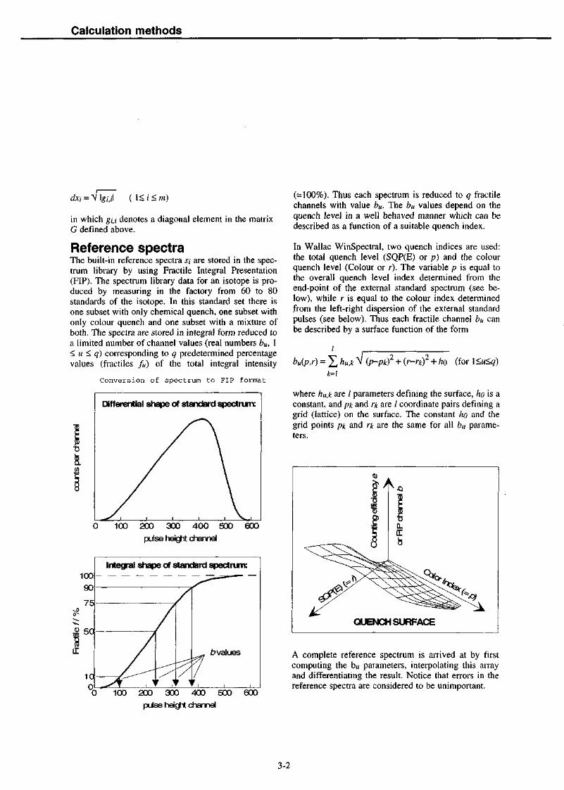
Reference spectraThe built-in reference spectra si are stored in the spec-trum library by using Fractile Integral Presentation(FIP). The spectrum library data for an isotope is pro-duced by measuring in the factory from 60 to 80standards of the isotope. In this standard set there isone subset with only chemical quench, one subset withonly colour quench and one subset with a mixture ofboth. The spectra are stored in integral form reduced toa limited number of channel values (real numbers bu, 1< u < q) corresponding to q predetermined percentagevalues (fractiles /«) of the total integral intensity
Conversion of spectrum to FIP format
Differential shape of standard spectrum:
0 100 200 300 400 500 600
pulse height channel
10090
75
50
10n
Intecyal shape of standard spectrum:
/
/
/
r J
/
f i
_ lvalues
Ir,0 100 200 300 400 500 600
pulse heicjit channel
(=100%). Thus each spectrum is reduced to q fractilechannels with value bu. The bu values depend on thequench level in a well behaved manner which can bedescribed as a function of a suitable quench index.
In Wallac WinSpectral, two quench indices are used:the total quench level (SQP(E) or p) and the colourquench level (Colour or r). The variable p is equal tothe overall quench level index determined from theend-point of the external standard spectrum (see be-low), while r is equal to the colour index determinedfrom the left-right dispersion of the external standardpulses (see below). Thus each fractile channel bu canbe described by a surface function of the form
bu(p,r) = + (r-rk)2 + h0 (for 1 <u<q)
k=\
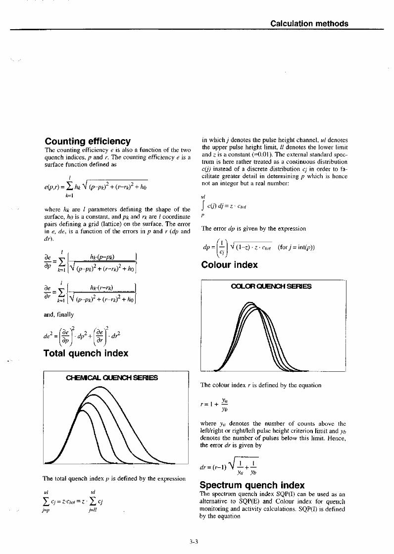
where hu,k are / parameters defining the surface, ho is aconstant, and pk and rk are / coordinate pairs defining agrid (lattice) on the surface. The constant ho and thegrid points pk and rk are the same for all bu parame-ters.
A complete reference spectrum is arrived at by firstcomputing the b« parameters, interpolating this arrayand differentiating the result. Notice that errors in thereference spectra are considered to be unimportant.
3-2
Calculation methods
Counting efficiencyThe counting efficiency e is also a function of the twoquench indices, p and r. The counting efficiency e is asurface function defined as
e(p,r) = (p-pkf + (r-rkf + hok=\
where hk are / parameters defining the shape of thesurface, ho is a constant, and pic and rk are / coordinatepairs defining a grid (lattice) on the surface. The errorin e, de, is a function of the errors in p and r (dp anddr).
I
k=[
I
k=\
ht(p-pk)
Vip-pkf + {r-rkf + ho
V (p-pkf + {r-rkf + ho
and, finally
Total quench index
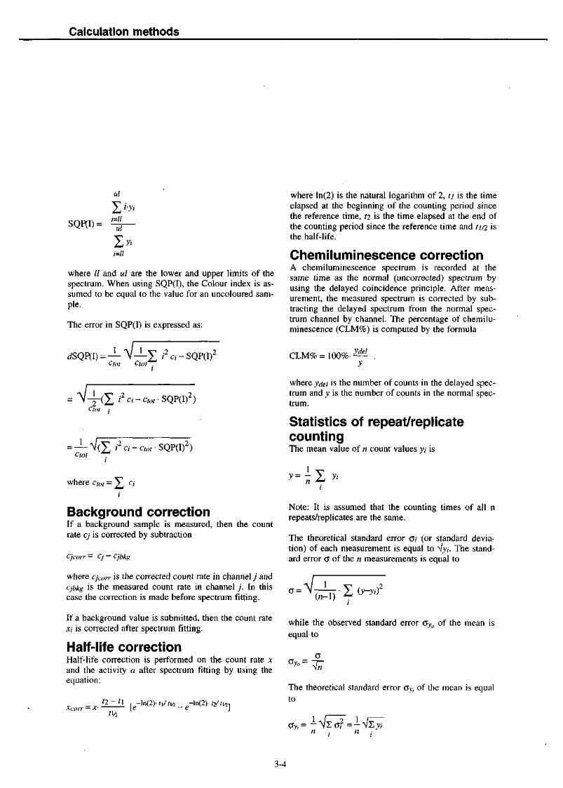
CHEMCAL QUENCH SERIES
The total quench index p is defined by the expression
ul id
, CJ = z-H>
in which j denotes the pulse height channel, ul denotesthe upper pulse height limit, II denotes the lower limitand z is a constant (=0.01). The external standard spec-trum is here rather treated as a continuous distributionc(j) instead of a discrete distribution CJ in order to fa-cilitate greater detail in determining p which is hencenot an integer but a real number:
ul
J
The error dp is given by the expression
dp = \-\ ^1 (l-z) • z • cot (for) = int(p))
Colour index
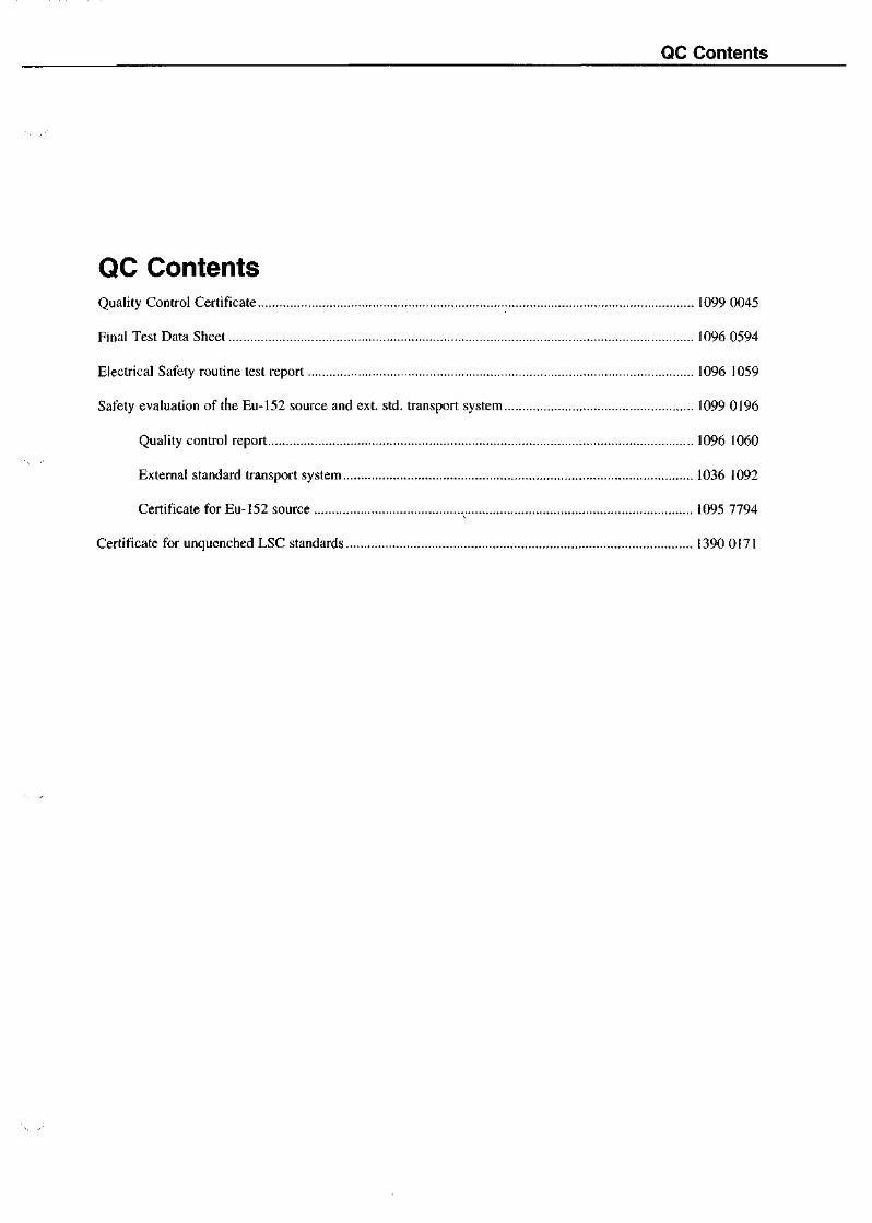
COLOR QUENCH SERIES
The colour index r is defined by the equation
r = l H — -
where ya denotes the number of counts above theleft/right or right/left pulse height criterion limit and ybdenotes the number of pulses below this limit. Hence,the error dr is given by
yb
Spectrum quench indexThe spectrum quench index SQP(I) can be used as analternative to SQP(E) and Colour index for quenchmonitoring and activity calculations. SQP(I) is definedby the equation
3-3
Calculation methods
SQP(I)=
id
where // and ul are the lower and upper limits of thespectrum. When using SQP(I), the Colour index is as-sumed to be equal to the value for an uncoloured sam-pie.
The error in SQP(I) is expressed as:
ctot
-j-(£ i2 a - ctot • SQP(I)2)Ctot :
1CtOt
SQP(I)2)
where ln(2) is the natural logarithm of 2, ti is the timeelapsed at the beginning of the counting period sincethe reference time, t2 is the time elapsed at the end ofthe counting period since the reference time and ti/2 isthe half-life.
Chemiluminescence correctionA chemiluminescence spectrum is recorded at thesame time as the normal (uncorrected) spectrum byusing the delayed coincidence principle. After meas-urement, the measured spectrum is corrected by sub-tracting the delayed spectrum from the normal spec-trum channel by channel. The percentage of chemilu-minescence (CLM%) is computed by the formula
CLM% = 100%-ydel
where ydel is the number of counts in the delayed spec-trum and y is the number of counts in the normal spec-trum.
Statistics of repeat/replicatecountingThe mean value of n count values yi is
where c,ot = £ c;yi
Background correctionIf a background sample is measured, then the countrate cj is corrected by subtraction
Cjcorr — Cj — Cjbkg
where cja>ir is the corrected count rate in channel j andcjblcg is the measured count rate in channel j . In thiscase the correction is made before spectrum fitting.
If a background value is submitted, then the count ratexi is corrected after spectrum fitting.
Half-life correctionHalf-life correction is performed on the count rate xand the activity a after spectrum fitting by using theequation:
U/2\e — e
Note: It is assumed that the counting times of all nrepeats/replicates are the same.
The theoretical standard error o; (or standard devia-tion) of each measurement is equal to Vy/. The stand-ard error a of the n measurements is equal to
(n-1) ^
while the observed standard error oy<l of the mean isequal to
Ov,,=0
The theoretical standard error ay, of the mean is equalto
3-4

Calculation methods
The theoretical standard error ay, can be _ compared tothe observed standard error Oyo by using the reduced
%r ("Chi-square") value:
2 °y<>
The degree to which %r deviates from unity is a directmeasure of the extent to which the observed error de-viates from the theoretical. %r multiplied by the 'de-grees of freedom' (=n-l) can be used to determine aprobability that a random sample from a normal distri-bution would have a larger (or smaller) value of %than the observed value.
List of symbols useda - activity (DPM)b = FIP channelc = measured total count rate (CPM)cj ~ measured channel count rate (CPM)C = an array (or column vector) comprising the meas-ured count rates cjd = error in function or parametere = counting efficiency/ = tractile valuegi,i = diagonal element of matrix GG = the matrix (ST*W1*S)'1
h = surface function parameteri = index to isotopej = index to channelk = index to surface function parameter/ = number of parameters defining the surfacem = maximum number of isotopesn = maximum number of channels or number of re-peats/replicatesp = total quench index (SQP(E))q - number of fractiles/r = colour quench index (Colour)si — reference spectrum, a column in Ssjj = channel value in reference spectrum, an elementin the matrix SS = a matrix containing the reference spectra .?;.t - counting time or elapsed timeti/2 = half-lifeit = index to fractile/and FIP channel bWJ - weight value for channel j , a diagonal element inthe matrix WW = the weight matrixx\ = unknown total count rate for isotope i, an elementin the array X
xij = unknown channel count rate for isotope iX = an array (or row vector) comprising the countrates x;y = number of countsz - fractile for total quench index pO = standard error at 68.3% confidence limit ( = stand-ard deviation)
Xr = reduced chi square


4 Quality control information

QC Contents
QC ContentsQuality Control Certificate 1099 0045
Final Test Data Sheet 1096 0594
Electrical Safety routine test report 1096 1059
Safety evaluation of the Eu-152 source and ext. std. transport system 1099 0196
Quality control report 1096 1060
External standard transport system 1036 1092
Certificate for Eu-152 source „ 1095 7794
Certificate for unquenched LSC standards 1390 0171

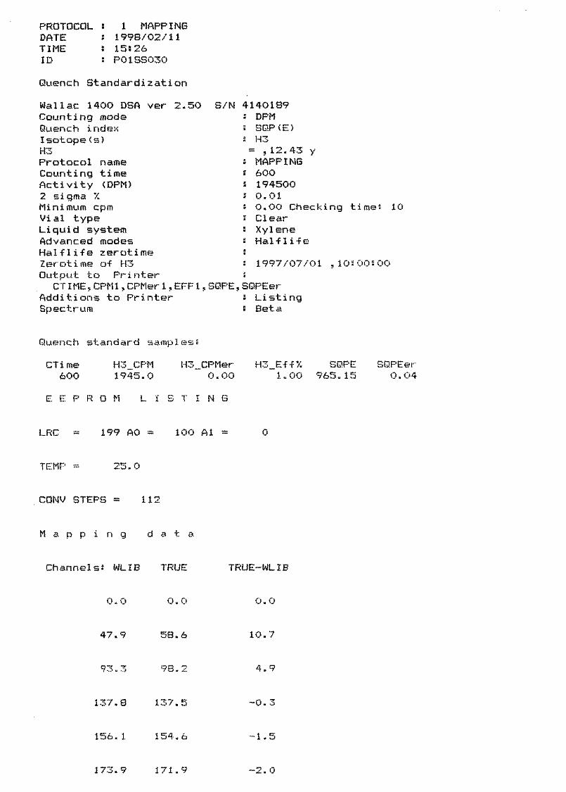
PROTOCOL 5DATE !TIME 5ID 5
1 MAPPING1998/02/1115526P01SS030
Quench Standardization
Wai lac 1400 DSA ver 2.50 S/N 4140189Counting modeQuench indexIsotope(s)H3Protocol nameCounting timeActivity (DPM)2 sigma XMinimum cpmVial typeLiquid systemAdvanced modesHalflife zerotimeZerotime of H3Output to Printer
CTIME 5 CPM1,CPMer1,EFF1,SQPE,SQPEerAdditions to PrinterSpectrum
DPMSQP(E)H3
= ,12.43 yMAPPING6001945000.010.00 Checking time: 10ClearXyleneHal-f li-fe
1997/07/01 , 105005 00
Li stingBeta
Quench standard samples?
CTime600
H3_CPM1945.0
H3__CPMer0. 00
H31 „ 00
SQPE965-15
SQPEer0.04
E E P R 0 M L I T I N G
LRC 199 AO = 100 Al =
TEMP =••• 25.0
CONV STEPS 112
M a p p i n g d a t a
Channels! WLIB TRUE TRUE-WLIB
0. 0 o. o 0.0
47.9 58.6 10.7
93.3 98,2 4.9
137.8 137. -0.
156. 1 154. & •1.5
173.9 171. 9 --2. 0


191.7 189. & ..... *"."= "!
210.6 208.6 • 1 . 9
(3 / / . £ 692= 4 15,2
740.9 765.3 24-4
793,3 831.5 3 8 ,
880.6 965.1 84™ 6
889.2 979, 90.3
915.3 1023.0 107, S
a p p j .ng C u r • v >-•
:i. 6 . 8@ .„
7. 58 __
CO
uLU
r5.ee _
2=58
i r r r
500
WLIE ch
+
• + • _ . . . - - - • "
+.-••"
r i i' 5 9
Total activity; H3 194500.0 DPM 3.242 kBq


PROTOCOL :DATE :TIME sID 3
9 3H, 14C,1998/02/1316^33P09AS018
BG Wai lac std
Wai lac 1414 WinSpectral vlCounting modeIsotope(s)H3C14Protocol nameCounting timeRepeatsCyclesReplicates2 sigma 7.Minimum cpmOutput to Printer
POS,CTIME,CPM1,CPM2,SQPIAdditions to PrinterOutput to DisplayPOS,RACKPOS,CPM,RPT,SQPI
Additions to Display"Spectrum
30 S/N 41401895 CPM5 H3,C14
5- 350,12.43 y5- 660,5730.00 y
3H, 14C, BG Wailac std.12004110.300.00 Checking times 10
, SQPE
WindowWindowWi ndowWindowWi ndowWindowFNCT1 =FNCT2 =FNCT3 =FNCT4 ~
173456FNCT1FNCT2FNCT3FNCT4
Listi ng
,CPM1,CPM2Listing,SpectrumBeta
1-1024 /Beta1-1024 /Beta1-1024 /Beta1-1024 /Beta1-1024 /Beta1-1024 /Beta
Unknown samp 1 es'•
Pos1111
•
Pos222*?
Pos3
-— -
Total.
CTime'*?'?'?
223223223
2220
CTi me274275275276
2750
CTi me1200120012001200
12000
count
H3_CPM127295,2127472.4127405.0127462.2
127408.781.3
H3_CPM26908.027007.727140.126906.3
26990.5110.4
H3_CPM16.817. 115.916.7
16.60. 5
rates
C14_CPM127402.2127566.7127507. .1127563.1
127509.876.7
C14_CPM102616.2102489.5102521,8102098.8
102431.6228.3
C14_CPM23.823.223.224. 1
23.60.5
H3C14
SQP I176.41175.94176.00176.01
176.090. 22
SQP I419.89419.50419.29419.38
419.520. 26
SQP I388.55389.95412.37407.87
399.6912.20
1544
SQPE966.42966.12965.14965.16
965.710.66
SQPE963.68961.01961.53963.36
962.401.32
SQPE965.66967.15966.59968.22
966.911 .07
15.9 CPM229964.9 CPM
REPEATS= Mean= St.Dev
REPEATS~ Mean= St.Dev
REPEATS~ Mean= St.Dev


PROTOCOL 5 8 SPECTRUMDATE ! 1998/02/16TIME 2 09-: 35TD s P08AS016
Unknown samples"
Pos CTime1 120
H3_CPM127526.4
C14_CPM127612.9
SQPI175.77
SQPE966.40
Spectrum Plot
758 _
598
a.o
259
Ch anne1 numb er
Total count rates H3 127526.4 CPMC14 127612.9 CPM


PROTOCOL 2iTE s
TIME :ID 2
S SPECTRUM1998/02/16095 40P0SAS017
Unknown sampless
Pas CTime H3_CPM C14_CPM SQPI SQPE2 120 27225.9 102986.0 4IB.90 963.06
Sp ec t r urn P1 ot
400 —
388 _
aj 208
189 __
758 i 888
Channel n u. m b e r
Total count rate' H3 27225=9 CPMC14 102986.0 CPM


PROTOCOL "• 15 14C Benz. protocolDATE s 1998/02/17TIME ! 16803FILE s AsS4140189SP15AS016.TXTID 5 P15AS016
Wai lac 1414 WinSpectralCounting modeIsotope(s)C14Protocol nameCounting timeRepeatsCycles"̂ epl icates2 sigma 7.Minimum cpmAdvanced modesPSA levelPAC levelOutput to Printer
POS,CTIME,SQPI,CPMwl,Additions to PrinterOutput to DisplayPOS,RACKPOS,CPM,SQPI,
Additions to DisplayPath of FileOutput to FilePOS,CTIME,SQPI,CPM1,
Additions to FileSpectrum
vl.30 S/N 4140189CPMC14
5- 660,5730.00 y14C Benz. protocol144001110.50O.OO Checking time* 10PSA,PAC85163
CPMw2,CPMw3,FNCTlListing
CPM1
WindowWindowWindowWindowWi ndowWindowFNCT1 =FNCT2 =FNCT3 =FIMCT4 =
12
C-4
456FNCT1FNCT2FNCT3FNCT4
Li sti ng,SpectrumasS4140189
,FNCT1Spectrum,ListingBeta200- 500 /Beta200- 500 /PACRejfl200- 500 /Alpha
1-1024 /Beta1-1024 /Beta1-1024 /Beta
(1OO*CPMW1/103600)
Unknown sampless
Pos CTime SQPI CPMwl CPMw21 115 339.50 78617.2 2381.92 14400 478.95 1.2 0.4
CPMw3 FNCT11225.1 75.9
0.1 0.0
Total count rates C14 88774.1 CPM

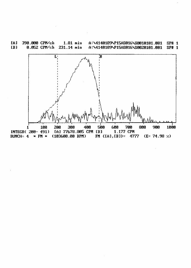
[A] 390.000 CPM/ch0.052 CPM/ch
1.81 win231.14
A:\4140189SP15AS016SS0010101.001 SPtt 1A:S4140189SP15AS016NS0020101.001 SPtt 1
1 100INTEGRC 288- 491)BUNCH^ 4 * FM *
T *-*—1 • r200 300 400 500 600 700[A] 77678.805 CPM [B] 1.177 CPM
(103608.00 DPM) FM ttA],[B]}= 4777
800 980 1000
(E= 74.98


PROTOCOL : 16 3h qs 8+12 PROTOCOLDATE : 1998/02/17TIME ! 20!07FILE i AiQ4140189QP16AS017.TXTID J P16AS017
S/N 4140189CPMH3
53h qs144001
350,12.43 y8+12 PROTOCOL
Wallac 1414 WinSpectral vl.30Counting modeIsotope(s)H3Protocol nameCounting timeRepeatsCycles s 1Replicates s 1? sigma % s 0.30.linimum cpm s 0.00Advanced modesHalflife zerotimeZerotime of H3 s 1993/04/01 ,00500:00PSA levelPAC levelOutput to Printer
POS,CTIME,SQPI,CPMw1,CPMw2,CPMw3,FNCT1Additions to PrinterOutput to Display
POS,CTIME,SQPI,CPMwl,CPMw25 CPMw3,FNCT1,RACKPOS,CPM,CPM1,RPT,DPMISpectrum,Listinga:Q4140189
Additions to DisplayPath of FileOutput to File
POS,CTIME,SQPI,CPM1,CPM2,CPM3,FNCT1Additions to FileSpectrumWindow"lindowWindowWindowWindowWindowFNCT1FNCT2FNCT3FNCT4
123456
= FNCT1= FNCT2= FNCT3- FNCT4
Checking times 10Half life,PSA,PAC
1993/04/01205120
Listing
Spectrum,Listi ngAlpha,Beta,PACRejft
20-'200 /Beta20- 200 /PACRejtf20- 200 /Alpha1-1024 /Beta1-1024 /Beta1-1024 /Beta
<1OO*CPM1/(207500))
Unknown samples:
Pos12
Total
CTime742
14400
count
SQP I112.01376.98
rates
CPMwl37358.6
4. 1
H3
CPMw21012.3
0.2
49359.
CPMw32229.9
1.5
1 CPM
FNCT123.80.0


[A] 550.000 CPH/ch 11.82 m i nEB] 8.160 CFM/ch 231.06 min
AA4140189SP16AS017SS0010101.001 SPtt 1A:S4140189SP16AS017SS0020101.001 SPtt 1
1 100INTEGRC 50- 143)BUNCH= 4 * FM *
200 300 400 500[A] 31700.805 CPM CB](158020.97 DPMco) FM
600 700 800 900 10082.021 CPM
199 (E= 20.06 '/J
Isotope; H-3 Half L i f e =STANDARD preparation date
measurement datedecay r a t i o (A/Ao)
12.43 Y= 01.04.93 12:00= 17.02.98 12:00= 0.7615
207500.00 DPM158020.97 DPM (decay corr . )

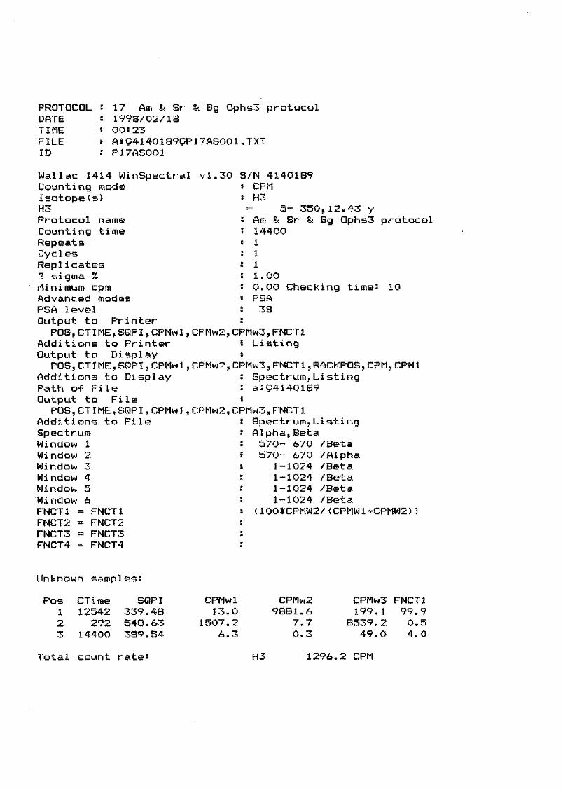
PROTOCOL 5 17 Am & Sr & Bg 0phs3 protocolDATE '• 1993/02/ ISTIME i 005 23FILE : A5S4140189gP17AS001.TXTID s P17AS001
Wallac 1414 WinSpectralCounting modeIsotope<s>H3Protocol nameCounting timeRepeatsCyclesReplicates1 sigma 7.flinimum cpmAdvanced modesPSA levelOutput to Printer
POS,CTIME,SQPI,CPMw1,Additions to PrinterOutput to Display
POS,CTIME,SQPI,CPMw1,Additions to DisplayPath o-f FileOutput to File
POS,CTIME,SQPI,CPMw1,Additions to FileSpectrum
vl.30 S/N 4140189i CPM8 H3
5- 350,12.43Am ?! Sr144001111.000.00 Checking timePSA38
Bg 0phs3 protocol
10
WindowWindowWindowWindowWindowWindowFIMCT1FNCT2FNCT3FNCT4
123456
= FNCT1= FNCT2= FNCT3= FNCT4
CFMw2,CPMw3,FNCTlListing
CPMw2,CPMw3,FNCT1,RACKPOS, CPM, CPM1Spectrum,Li st i ngas^4140189
CPMw2,CPMw3s FNCT1s Spectrum,ListingAlpha,Beta570- 670 /Beta570- 670 /Alpha
1-1024 /Beta1-1024 /Beta1-1024 /Beta1-1024 /Beta
(1OO*CPMW2/(CPMW1+CPMW2))
Unknown sampless
Pos CTime SQPI CPMwl CPMw21 12542 339.48 13.0 9881.62 292 548.63 1507.2 7.73 14400 389.54 6.3 0.3
CPMw3 FNCT1199.1 99.9
8539.2 0.549.0 4.0
Total count rates H3 1296.2 CPM


[A] 240.000 CPM/ch 200.91 min0.060 CPM/ch 231.09 min
A:S4140189SP17AS001SS0010101.001 SPtt 4A:S4140189SP17AS001SS0030181.001 SPtt 4
1 100 200 300 400 500INTEGRC 584- 657) [A] 9404.063 CPM CB]BUNCH= 4 * FM * ( 9894.68 DPM) FM
600 700 800 900 10000.195 CPM
^ 46385 CE= 95.04 yJ

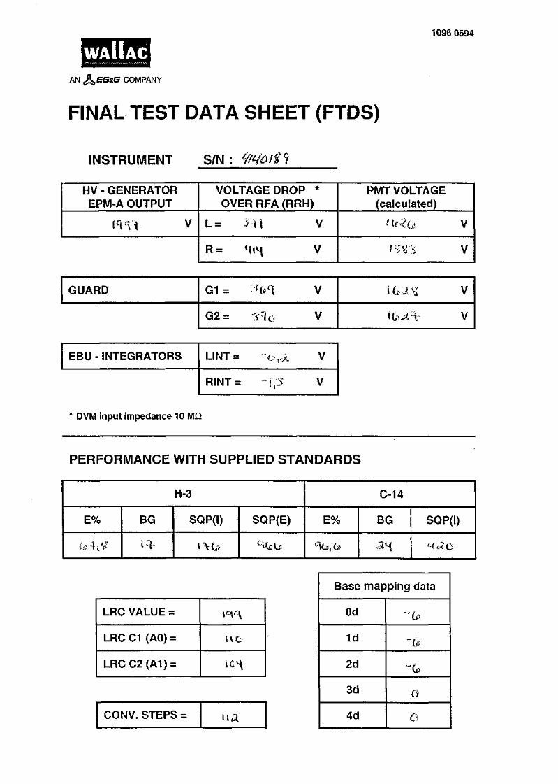
WAIIAC1096 0594
AN COMPANY
FINAL TEST DATA SHEET (FTDS)
INSTRUMENT S/N:
HV - GENERATOREPM-A OUTPUT
i<m v
VOLTAGE DROP *OVER RFA (RRH)
L= H i V
R = Hi<{ V
PMT VOLTAGE(calculated)
n^a v
'sirs v
GUARD G1 =
G2 =
EBU - INTEGRATORS LINT =
RINT =
* DVM input impedance 10 MD.
V
V
V
PERFORMANCE WITH SUPPLIED STANDARDS
H-3
E% BG
l-q-
SQP(I) SQP(E)
C-14
E% BG
an
SQP(I)
LRC VALUE =
LRC C1 (AO) =
LRCC2(A1) =
CONV. STEPS = ha
Base mapping data
Od
1d
2d
3d
4d
"6
0
o


WAIIAC
UNQUENCHED LSC STANDARDfor
Liquid Scintillation CounterProduct No.: 1215-111
CERTIFICATE
Radioactive isotopes: tritium, carbon-14 and blank
The absolute activities of standards and the referencedates for all standards are as follows:
3H : 194500 dpm 1. Jul 1997 Ref. Date
1 4 C: 106000 dpm Nov1997 Ref. Date
Blank: Feb 1997 Ref. Date
The 1215-111 is from the production Lot No.: 9702 A ;
Product Description: The 1215-111 Liquid ScintillationStandards set consists of two activity standards and oneblank standard. The activity standards are preciselycalibrated, sealed unquenched samples of carbon-14labelled [1-14C] stearic acid and tritium labelled [7(n)-3H]-cholesterol in 10 ml of xylene based scintillationsolution. The labelled compounds are produced byDuPont NEN, Belgium and Amersham International, UK.The unquenched blank standard is a sample of 10 ml ofxylene based scintillation solution. The standards aresupplied in 20 ml capacity low potassium contentWheaton vials. These are flame-sealed and securedwith white silicon mastic and an aluminum cap.Str>ndards are deoxygenated with pure nitrogen beforet Jing.
Activity Calibration : The tritium standards arecalibrated against reference standards of tritium labelledtoluene by the National Institute of Standards andTechnology (NIST), Standard Reference Material(SRM) No. 4947C, the estimated accuracy of which was+ 1.2%. The Carbon-14 standards are calibrated againstreference standards of n-hexadecane-1-14C supplied bythe National Institute of Standards and Technology,Standard Reference Material (SRM) No. 4222C, theestimated accuracy of which was + 0.81%. The absoluteactivity of the standards is within + 0.5% of the referencestandards of NIST SRM's.
Definition of Use: The 1215-111 unquenched standardsset is intended for use with LS-counter Serial No: ¥N0^j
On behalf of the Quality Control Department
V JacOyP.O. Box 10SF-20101 TurkuFinland
to calibrate the instrument and measure day-to-day 3H and14C counting efficiencies and background for comparisonwith original factory specifications and for verifying stablesystem performances. For specific instructions on the use ofthese standards with an LS-counter, the Instrument manualshould be consulted.
Precautions on Storage and Use : Fluors are susceptibleto photo-chemical degradation. The standard set should bestored in a dark place at room temperature. Recommendedshelf-life is not more than 5 years.
1390 0171


WAIIACAN J^EGsJS COMPANY
M. Ala-UotilaDoc. no 10961059
Electrical safety routine test report
Product nameProduct numberSerial number
Test description
Protective Earth ContinuityMeasured between the
ground terminal of the mainsconnector and accessiblemetal parts.
Dielectric Strength1500 V AC is applied
between the mains input andthe ground terminal for 1minute.
Earth Leakage CurrentThe current through the
ground lead is measuredduring normal operation.
The test is repeated withmains polarity reversed.
1400 DSA1414- 00-34140*^1
Limits
max. 0.10 ohm
The leagake currentrejection limit is 12.5mA, including thecurrent through EMIsuppression capacitors.(Defined in the UL-Client's TestData Program)
max. current 0.50 mA
max. current 0.50 mA
Test results |
c.c^ ohm
Result of the test
Signature 'H
oau m A
mA
The tests have been performed with the measuring equipment which belong to the regularWallac calibration program.
Tests performed by: Date:


1390 3693
WAIIACAN Ji^BBia COMPANY
DECLARATION OF CONFORMITY FOR CE-MARKING
We
Supplier's name
WALLAC OY
Address
PL 10, 20101 TURKU, FINLAND
declare under our sole responsibility that the product
Name, type or model, lot, batch or serial number, possibly sources and numbers of items
1414 Liquid Scintillation Counter Valid from serial number 4140044
to which this declaration relates is in conformity with the following standard(s) or other normative document(s)
Title and/or number and
EN
EN
50082-1
61010-1
:1992
:1993
date of issue of
; EN 50081-1
the standard(s)
:1992
or other normative document(s)
(if applicable) following the provisions of the following directives
Electromagnetic compatibility (EMC), 89/336/EEC
Low voltage (LV), 73/23/EEC
Place and date of issue
12 Nov. 1997 Turku, Finland
Name and signature or equivalent marking of authorized person
Heikki Kouru, Quality Assurance Manager _


WAIIACAN COMPANY 1096 1060
Quality Control Report
Name of Product:Manufacturer:Function Tested:
Activity of the capsule:
1400-Series Liquid Scintillation CountersWaIIac Oy, Turku, FinlandClassification of External Standard Capsule Eu-152 accordingto ISO 2919.440 kBq
CERTIFICATION
Eu-152 External standard source has been tested according to ISO 2919 - 'Sealed RadioactiveSources - Classification'.
The tests are:Test
Temperature
Ext. pressureImpactVibration
Puncture
Leakage tests according to ISO TE
Class Short definition
4 - 40 °C (20 min)+ 400 °C (1 h) and thermal shock to 20 °C
3 25 kPa abs. to 2 MPa abs.4 2000 g from 1 m3 2 times 10 min, two axes
25 Hz to 50 Hz/5G,50 Hz to 90 Hz/0.635 mm amplitude,90 Hz to 400 Hz/lOG
4 50 g from 1 m
.. 4826 have been performed after the classification tests.The tests show no significant leakage.
The source fulfils ISO 2919 requirements and is therefore classified as C43434.
Date: 25 Nov. 1994
Signature of controllerRaimo Kananen, M.Sc.PhysicistQuality Assurance Department, Instruments


1099 0196November 1995
Evaluation of the safety of the Eu-152 external standard source inWallac 1400 series LS counters
IsotopeEuropium 152.
Maximum activity12 microcuries (half-life 13.5 years).
Origin of radioactive materialThe Eu-152 radioactive material is made by the Radiochemical Centre, Amersham, England.
Manufacturer of the standard capsulesThe Eu-152 standard capsules are manufactured by Wallac Oy, Finland.
Manufacturing processThe manufacturing process by which the radioactive standards are produced involves two steps: the preparation ofthe radioactive material and the encapsulation of this material with a metal cover.
In the manufacturing process the active Eu-152 solution (1 mCi/ml) is absorbed homogeneously into crystallinesynthetic zeolites in such a way that the activity of each active source is 12 (iCi.
The active source is enclosed in a stainless steel shield of thickness 0.35 mm. The source is sealed first withsilicon rubber and then the shield is closed by using a stainless steel pin, which is held in place by pinching theshield with a special tool. The wire that moves the capsule is then inserted into the shield and fixed in place byagain pinching the shield.
ISO-testThe capsule has been tested by the Quality Assurance department of Wallac Oy according to the ISO 2919standard. The rating C43434 has been achieved.
External standard transport systemThe transport system is illustrated in document 1036 1092.
The standard is mounted on a metal wire which is moved by two friction wheels controlled by a stepper motor andtwo sensors.
The capsule has two stable positions in the transport system; one in the storage shielding and the other in themeasuring chamber inside the lead shielding. The storage shield is made of lead (thickness 50 mm) and isequipped with a radiation hazard warning label. This includes a definition of the isotope and its activity.
The capsule is transported to the measuring chamber along a PA (polyamide) tube and a stainless steel elevatortube. The transport time is less than 3 seconds.
Disposal of the capsuleWhen the instrument is no longer in use, the Eu-152 standard capsule must be removed and sent to the appropriateradiation safety authorities or to Wallac for safe disposal. This procedure must be performed only by a qualifiedWallac service engineer.

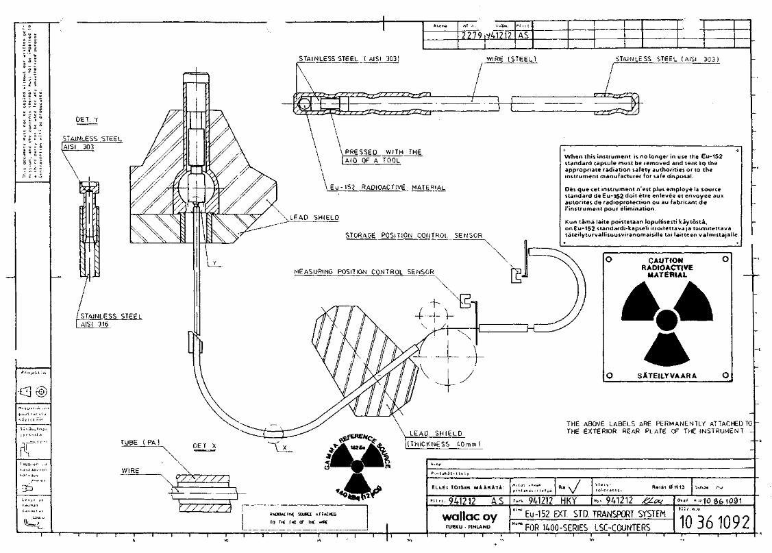
STAINLESS STEEL I AISI 303! WIRE (STEEL)
•C3®
j » r s , . . l j
—r
PET Y
STAINLESS STEEL
PRESSED WITH THEAID OF A TOOL
Eu-152 RADIOACTIVE MATERIAL
STORAGE POSITION CONTROL SENSOR
MEASURING POSITION CONTROL SENSOR
STAINLESS STEEL
LEAO SHIELD
(THICKNESS 40mm
ELLEI TOISIN MAARATA.
| 10 I K EX) OF TK wBt
1 1 1 1 1 1 1 1
STAINLESS STEEL (AISI 303)
When this instrument is no longer in use the Eu-152standard capsule must be removed and sent to theappropriate radiation safety authorities or to theinstrument manufacturer for safe disposal.
Oes que cet instrument n'est plus employe la sourcestandard de Eu-152 doit etre enlevee et envoyee auxautorites de radioprotection ou au fabricant deI'instrument pour elimination.
Kun tama laite poistetaan lopullisesti kaytdsta.on Eu-152 standardi-kapseli irroitettava|a taimitettavasateilyturvallisuusviranomaisille tai laitteen valmistajalle
CAUTIONRADIOACTIVE
MATERIAL
O SATEILYVAARA O
THE ABOVE LABELS ARE PERMANENTLY ATTACHED TOTHE EXTERIOR REAR PLATE OF THE INSTRUMENT -
Rent 0H13 Sunje ^j
941212 HKY " . -941212"'"' Eu-152 EXT. STD. TRANSPORT SYSTEM
-l 1 r r _ — r
FOR 1400-SERIES LSC-COUNTERS 10 361092-i r


WAIIAC1095 7794
CERTIFICATEfor
SEALED RADIOACTIVE SOURCE
Manufacturer: WaIIac OyP.O.Box 1020101 TURKU 10FINLAND
Batch No: 7C
Serial No:
Description of theRadionuclide:
Max. activity:
ISO classification:
Leakage test:
EU-152 gamma source in stainless steel shield of thickness0.35 mm.
Active length 1.3 mm.
440 kBq (12u€i)
ISO 2919 C43434
The sealed source is immersed in distilled water. The water isheated to 323 ± 5 K and held at this temperature for 4 h. Thesealed source is then removed and the activity of the water ismeasured with a liquid scintillation counter. Activity levelsexceeding 185 Bq will be cause for rejection.
Result of test:
Date of test:
Passed
15/09/97
Signature:


5 Installation information

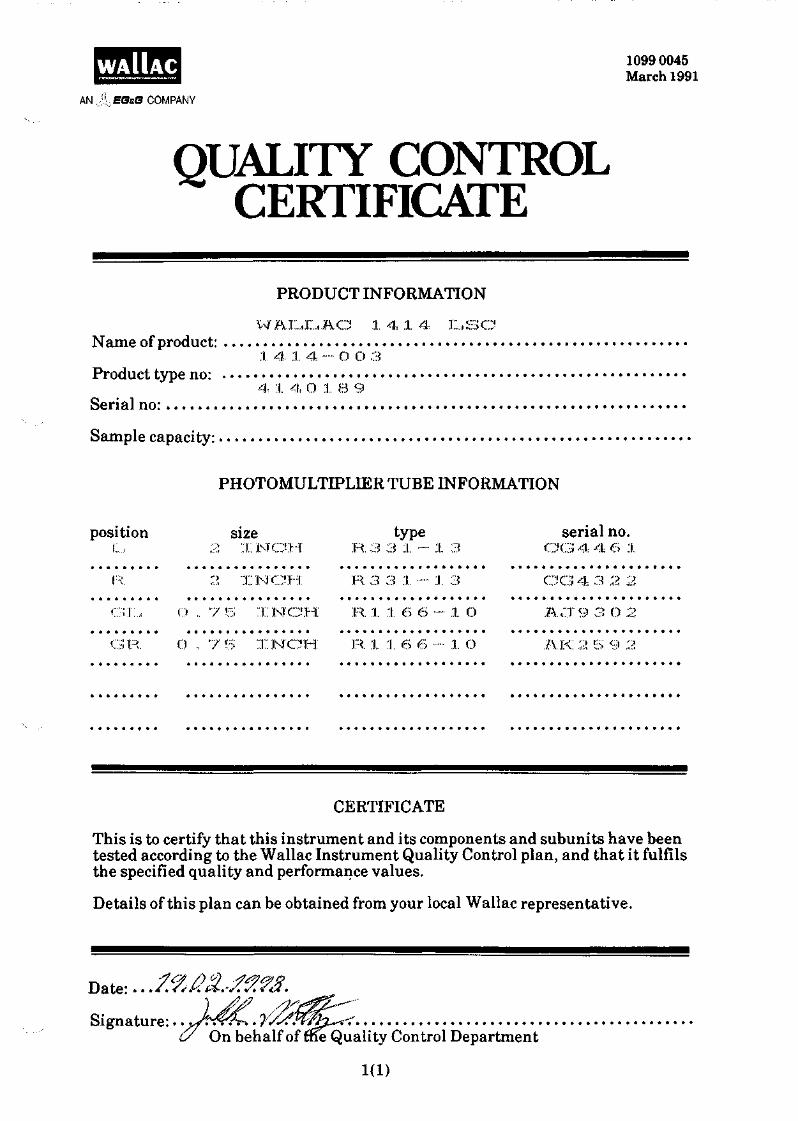
WAIIACAN EGsG COMPANY
1099 0045March 1991
QUALITY CONTROLCERTIFICATE
PRODUCT INFORMATION
WALLAC 1 4 1 4 LSCName of product:
1 4, l 4 — O O 3Product type no:
4 1 4 O 1 8 9Serial no:Sample capacity:
PHOTOMULTIPLDER TUBE INFORMATION
position size type serial no.
"IL., 2 INCH R.3 3 1 — 1 3 C G 4 4 6 1
R. 2 INCH R. 3 3 1 ••- 1 3 CG 4 3 2 2
GL., O .. '7 5 INCH R. 1 1 €> 6 — 1 O ACT9 3 O 2
GR O -, V 5 INCH R .1.. 16 6 1 O !1K 2 5 9 2
CERTIFICATE
This is to certify that this instrument and its components and subunits have beentested according to the Wallac Instrument Quality Control plan, and that it fulfilsthe specified quality and performance values.
Details of this plan can be obtained from your local Wallac representative.
Date: . . . / .
Signature:. .yftOn behalf of me Quality Control Department
1(1)


1086 1430September 1995
WarningThis equipment must be installed andused in accordance with themanufacturer's recommendations.Installation must be performed byproperly trained and authorisedpersonnel.
Failure to follow these instructions mayinvalidate your warranty and/or impairthe safe functioning of your equipment.
Please contact your local Wallacrepresentative for installation.
WALLAC


Installation information
InstallationEnvironmentNormal clean laboratory conditions usually provide asatisfactory operational environment, but the followingpoints should be taken into consideration.
Ideally a separate room should be provided for yourWallac 1414 WinSpectral counter as this allows thebest control over the immediate environment. Ventila-tion should be adequate for all conditions of use, thetemperature should be reasonably constant at about22°C, relative humidity should not be excessive, anddirect sunlight should not be able to reach the instru-ment. It is also important that the various isotopes arestored well away from the instrument in another room.Only those radioactive samples that are actually beingmeasured should be in the laboratory at any time inorder to keep the background at a low level.
Electric powerThree electrical outlets should be available, with, ifpossible, a separate power line for the instrument itselfhaving an isolation switch and a fuse box. If excessivefluctuations in the mains voltage are anticipated, amains stabilizer may be necessary.
UnpackingTo unpack the instrument proceed as follows (see fig.5.1).
Cut off and remove the binding bands. Open theclinching nails and lift off the cover. Unpack the sepa-rate packages. Then open the lower clinching nails andremove the box. Unscrew the fixing screws. Lift theinstrument up from the shipping package base and un-screw the suspension bushes from the frame.
Check all units and accessories against the packinglist. Note any possible transport damage.
Move the instrument to its place of operation.
Installing the lead shieldingRemove the screws holding the back panel (fig. 5.2).
Fig. 5.1 Unpacking the instrument and accessories
Fig. 5.2 Removing the screws
5-1

Installation information
Remove the back panel (fig. 5.3)
Fig. 5.3 Remove the back panel
Unscrew and remove the PC board (fig. 5.4).Fig. 5.6 Releasing the inner cover
Pull the top cover forward and remove it (fig. 5.7).
Fig. 5.4 Remove the PC board
Unscrew the top cover screws (fig. 5.5).
Fig. 5.7 Pull the top cover forward
Install the lead shielding for 1414-001 WinSpectral asshown (fig. 5.8) the lead sections are numbered.
1 2 1 3
Fig. 5.5 Releasing the top cover
Remove the additional screws securing the inner cover(fig. 5.6).
Fig. 5.8 Installing the shielding for WinSpectral
In the case of1414-002 Win-Spectral a/p, firstplace the two iden-tical pieces of lead F'9- 5-9
shielding with aSSKSformetal supports on WinSpectraltop of the PMTs a/paround the tube forthe counterweight,see fig. 5.9.
5-2
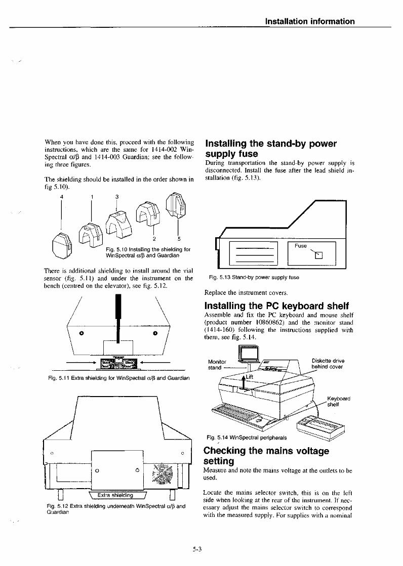
Installation information
When you have done this, proceed with the followinginstructions, which are the same for 1414-002 Win-Spectral a/p and 1414-003 Guardian; see the follow-ing three figures.
The shielding should be installed in the order shown infig 5.10).
4 1 3
Fig. 5.10 Installing the shielding forWinSpectral cx/p and Guardian
There is additional shielding to install around the vialsensor (fig. 5.11) and under the instrument on thebench (centred on the elevator), see fig. 5.12.
Fig. 5.11 Extra shielding for WinSpectral a/p and Guardian
IT \ Extra shielding /
Fig. 5.12 Extra shielding underneath WinSpectral a/p andGuardian
Installing the stand-by powersupply fuseDuring transportation the stand-by power supply isdisconnected. Install the fuse after the lead shield in-stallation (fig. 5.13).
t\/
Fuse
Fig. 5.13 Stand-by power supply fuse
Replace the instrument covers.
Installing the PC keyboard shelfAssemble and fix the PC keyboard and mouse shelf(product number 10860862) and the monitor stand(1414-160) following the instructions supplied withthem, see fig. 5.14.
Monitorstand
Diskette drivebehind cover
Keyboardshelf
Fig. 5.14 WinSpectral peripherals
Checking the mains voltagesettingMeasure and note the mains voltage at the outlets to beused.
Locate the mains selector switch, this is on the leftside when looking at the rear of the instrument. If nec-essary adjust the mains selector switch to correspondwith the measured supply. For supplies with a nominal
5-3

Installation information
WinSpectral
Cables (Options]1221-470 (9 pin)1221-503 (9 pin with shielding]1221-459 (25 pin)
Fig. 5.15a Cables when raw printer connected to PC
1 PC
LPT1Any LPT ornerworK primer
Cable 1224-122
Windowsprinter
Raw data printerAny Epson Fx compatible
Printerport 1(serialline)
WinSpectral
PC port 2
PC
Cable 1221-456
Raw data printerAny Epson Fx compatible
Fig. 5.15b Cables when raw printer connected to WinSpectral
Windowsprinter
Note: The factory settings of the printer maynot correspond to those used in WinSpectral.If printing does not function properly, checkthe settings according to the informationgiven in Serial port settings
voltage of 230 V it is recommended that the selectorbe set to 240 V.
Check that the fuses fitted in the fuse carriers on theback panel are of the correct rating for the local sup-ply, and according to the label.
Connecting the counter andperipheralsConnect the counter to the PC and the printer(s) usingthe cables shown in fig. 5.15 above. As well as thenormal PC Windows printer e.g. a network laserprinter, you can also have a raw data printer. Normallythis will be connected to the PC (fig. 5.15a), but you
can have it connected to WinSpectral directly in port 1(fig. 5.15b).
The PC is connected to port 2 of the counter.
The third port is not used and should have a blankingconnector (1086 0713).
Further details of the settings for the printer are givenin its own installation sheet which follows these instal-lation instructions.
Plug in the power cables for each device.
5-4

Installation information
Installing the PC softwareInstall the WinSpectral following the instructions inthe User manual.
After installation, start the program by double clickingthe 1414 WinSpectral icon in the WinSpectral win-dow.
When the WinSpectral main window appears, you willsee at the bottom the status bar; this is divided intofour sections. In the third and fourth there are the dateand time respectively. In the second there is a messageabout the communication status. If the counter is notswitched on then there will be a message "No responsefrom counter".
Starting the counterLift the instrument cover and then the diskette drivecover. This latter should be lifted straight up first torelease it. Then insert the instrument program disketteinto the diskette drive in the counter and replace thecover. Do not remove the program diskette.
Switch on the counter. The message on the status barwill change to "Counter online". During the loadingprocess the status bar will show the following mes-sages: "Loading DOT", "Loading texts" and "Loading1400 program". When the program is completelyloaded, the message "Counter idle" will appear. Load-ing takes some 2 minutes.
Note: The program diskette labelled BACKUP mayalso be used but be sure to always have a programdiskette in addition to the one in the instrument. Whenneeded make a backup copy using the "Backup instru-ment disk" function in the System menu. It is also rec-ommended that from time to time you make a backupcopy of your program diskette to save your own proto-cols and spectrum libraries.
Note: You should also make backup copies of theWinSpectral program diskettes before use. Use e.g. theCopy disk function in your Windows File manager.
Carrying out a functional checkof the instrumentFor checking the instrument mechanically and forchecking the function of the ID reader proceed as fol-lows:
Load some racks with ID labels, then start countingand check that the instrument will change the protocolas required by the labels.
Performance test with Easy GLPTo define the proper values for GLP you have to makean initial measurement of the local background. Makesure that all stationary and moving gamma sources areremoved from the neighbourhood of the instrument.Use at least 300 s measurement time.
Start the editing of the Easy GLP protocol (see page52 in the User manual). Type the values of the sup-plied standards into the text box marked Referencesamples. The isotope windows are 5-350 for H and5-650 for C. The measurement time should be 300 sor longer and the precision 0.5%.
Test values are as follows (where FTDS means theFinal Test Data Sheet included with the Instrumentmanual):
' H background
H efficiency3H SQPXI)
C background
C efficiency14C SQP(I)
Min
-3%-5ch
-2%-5ch
Max
+ 1%+3ch
+ 1%+3ch
CommentUse the localbackground*from FTDS valuefrom FTDS valueUse the localbackground*from FTDS valuefrom FTDS value
*The minimum and maximum background warninglimits for GLP are calculated from "the value meas-ured during installation +/- 3o". Some example back-grounds and 3a limits are:
Observed background46-5041 -4536-4031 -3526-3021 -2516-2011 - 156 - 100 - 5
3a9.59.08.57.97.36.76.05.24.23.0
5-5

Installation information
E.g. if your background is 21 then 3a is 6.7 whichmeans the minimum and manximum limits are 14.3and 27.7 respectively. You can calculate the 3a fromthe expression 3a = 3 * SQRT (BGD/t) where BGD isthe measured mean background rate in the windowand t is the counting time in minutes.
Note: a typical change in efficiency of 2% for H overa period of a year may be expected.
Serial port settingsThe factory settings of the printer serial port on Win-Spectral are as follows:Baudrate: 4800 PCParity: NoData bits: 8Stop bits: 2Handshake: DTR i.e. ESNThese settings may be changed by selecting Systemparameters in the System menu. See the User manualon page 71.
5-6
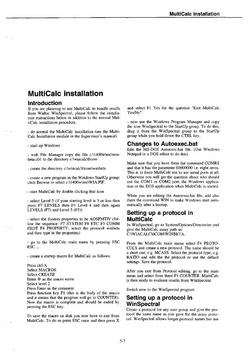
MultiCalc installation
MultiCalc installationIntroductionIf you are planning to use MultiCalc to handle resultsfrom Wallac WinSpectral, please follow the installa-tion instructions below in addition to the normal Mul-tiCalc installation procedure.
- do normal the MultiCalc installation (see the Multi-Calc Installation module in the Supervisor's manual)
- start up Windows
- with File Manager copy the file c:\1400w\mc\win-beta.cOl to the directory c:\wiacalc\Ocom
- create the directory c:\wiacalc\Ocom\winbeta
- create a new program in the Windows StartUp group:click Browse to select c:\1400w\mc\WIA.PIF.
- start MultiCalc by double clicking that icon
- select Level 5 (if your starting level is 3 or less thenpress F7 LEVELS then F4 Level 4 and then againLEVELS (F7) and Level 5 (F5))
- select the System properties to be AOSPMTIV (fol-low the sequence: F7 SYSTEM F8 ETC F3 COMMPROT F4 PROPERTY, select the protocol winbetaand then type in the properties)
- go to the MultiCalc main menu by pressing ESCESC ...
- create a startup macro for MultiCalc as follows:
Press Ctrl ASelect MACROSSelect CREATEEnter @ as the macro nameSelect level 2Press Enter as the commentPress function key Fl (this is the body of the macroand it means that the program will go to COUNTER).Now the macro is complete and should be ended bypressing the ESC key.
To save the macro on disk you now have to exit fromMultiCalc. To do so press ESC once and then press X
and select Fl Yes for the question "Exit MultiCalcYes/No".
- now use the Windows Program Manager and copythe icon WinSpectral to the StartUp group. To do this,drag it from the WinSpectral group to the StartUpgroup while you hold down the CTRL key.
Changes to Autoexec.batEdit the MS-DOS Autoexec.bat file. (Use WindowsNotepad or a DOS editor to do this).
Make sure that you have there the command COMRSand that it has the parameter 00000000 i.e. eight zeros.This is to force MultiCalc not to use serial ports at all.Otherwise you will get the question about who shoulduse the C0M1 or COM2 port, the Windows applica-tion or the DOS application when MultiCalc is started.
While you are editing the Autoexec.bat file, add alsothere the command WIN to make Windows start auto-matically after a bootup.
Setting up a protocol inMultiCalcIn WinSpectral, go to System/Options/Directories andgive the MultiCalc assay path as:C:\WIACALC\0COM\WINBETA.
From the MultiCalc main menu select F4 PROTO-COLS and create a new protocol. The name should bea short one, e.g. MCASS. Select the protocol type, e.g.RATIO and edit the the protocol or use the defaultsettings. Save the protocol.
After you exit from Protocol editing, go to the mainmenu and select from there Fl COUNTER. MultiCalcis then ready to evaluate results from WinSpectral.
Switch now to the WinSpectral program.
Setting up a protocol inWinSpectralCreate a protocol for any user group and give the pro-tocol the same name as you gave for the assay proto-col. WinSpectral allows longer protocol names but use
5-7

MultiCalc installation
exactly the same name as for the assay protcol, e.g.MCASS.
Set the counting time and the isotopes used. Then goto Output devices and select Filing data. Click theMore button and select MultiCalc export. Save thesesettings.
You are then ready to run the protocol.
WinSpectral will receive data and save it on the harddisk of the PC. As the samples in the assay are beingcounted, WinSpectral will create a file in the Multi-Calc communication protocol directory. MultiCalc willfind the file and start evaluating it in about 30 secondsdepending on the speed of your PC and the amount oftime you have given for DOS applications.
5-8

INSTALLATION REPORT APPENDIX
Please fill in the following information about the type of work the instrument is to beused for. We would also be pleased to get some brief feedback about your opinionsconcerning Wallac as a company.
Service specialist fills in:
Instrument type: Serial no:_ Country:.
Customer fills in:
Name & Profession:
Fax no:
This instrument is used as described below (x):
Main segment:Clinical DiagnosticsAcademic ResearchIndustrial ResearchEnviron. Research
Data management:Software:
NoneRia/MultiCalcWorkstationOther
Connections:PCLocal networkMainfame
Rate the importance of the items below on a scale of 1 to 5 (1= not important,5= very important). In the column Wallac put a (+) mark if you think the companydoes well for that item and a (-) mark if you think it should do better.
Ratingnot very
imp. imp.
1 2 3 4 5
Wallac
PRODUCT PRICEQUALITY&RELIABILiTYTECHNOLOGYFEATURESPERFORMANCEEASE OF USEDATA MANAGEMENTSUPPORT&SERVICESYSTEM SUPPLIERCOMPANY IMAGE
Other comments:


6 Specifications, Safety and Routinemaintenance


6.1 Specifications
6.1 SpecificationsDescriptionWallac 1414-001 WinSpectral, 1414-002 WinSpectraloc/p and 1414-003 Guardian are general purpose liquidscintillation counters for counting sample vials fromracks.
Physical dimensionsWidthHeightDepthWeight
900 mm700 mm600 mm218 kg (WinSpectral), 250kg(WinSpectral a/B), 244 kg (Guardian)
PowerMains voltage selectable 100, 115, 120, 220 and 240V, +/-10%, 50/60 Hz. Power consumption is 200 VAwithout the temperature control unit and 300 VA withit.
Standby power supplyPower failure recovery and protection by back-upstandby power supply provided with NiCd accumula-tors. In the case of power failure the status of thecounting process will be stored on diskette, thus pro-viding effectively an unlimited standby time for recov-ery from power failure.
Input/output connectionsSerial ASCII interface RS-232C. Two output termi-nals: port 1 for printer, port 2 for laboratory PC.
Radiation shieldLow specific activity lead around detector assemblyand external standard rest position. Weight 103 kg(WinSpectral), 135 kg (WinSpectral oc/B), 128 kg(Guardian), thickness at least 48 mm around the meas-uring chamber.
Operating conditionsTemperature +15 to +35 °CHumidity max. 75 %.
FlexiRack™ sample changerand conveyorSample capacity varies from 336 to 1248 vials, de-pending on the used rack combination. When usingonly standard vial racks, 336 samples in 28 racks of 12samples each. With minivial racks, 720 samples in 40
racks of 18 samples each. With small mini/microvialracks, 1248 samples in 52 racks of 24 samples each.
Rack transport by friction belt drive system, transversemovement by toothed chain driven by electric motors.Sample lifted up to measuring chamber by elevatordriven by electric motor, single "dual plate" light shut-ter system, sample change time 5 s. Rack and sampleposition movements controlled by electro-optical sen-sors.
Optional external standardEu-152 450 kBq (12 ^Ci) enclosed in a stainless steelcapsule.
Optional temperature controlunitControls sample and instrument +/- 5 °C of ambient.
Detector assemblyTwo PM tubes in coincidence. Assembly includes alsolight emitting diodes for the automatic spectrum stabi-lizer. Coincidence resolution time is 15 ns.
Racks and modification kitsSample racks1410-401 for 20 ml vials, max. vial diameter 28.4 mm,12 sample positions per rack.
1410-402 for 6 ml vials, max. vial diameter 18.4 mm,18 sample positions per rack.
1410-403 for 4 ml vials, Skatron or Biovial, max. vialdiameter 13.4 mm, 24 sample positions per rack.
Max. acceptable vial height is 68 mm.
Rack modification kits1410-408 for Eppendorf tubes to be used in 1410-402racks.
1410-409 for microfuge tubes to be used in 1410-403racks.
Poslden™ sample identificationsystemEach rack can be provided with a 1410-407 ID clip for1450-452 ID labels. The ID clip has two marked areas,
6-1
6.1 Specifications
the upper for the protocol number and the lower forrack number or special code. This provides the infor-mation needed for Good Laboratory Practice.
Electronic hardwareA 16-bit microprocessor controls counting and data re-duction. Memory configuration is 64 kbyte ROM and1 Mbyte RAM.
Logarithmic A/D converter, energy range 1 - 2000keV. Dual 1024-channel multichannel analyzer. Built-in dead time correction.
PerformanceEfficiencyCounting efficiency, typical:3H : 68 % (min. 64 %)14C : 96 % (min. 94 %)
StabilityCount variation less than 0.2 % / 24 h (not includingrandom statistics).
6-2

6.2 Safety information
6.2 Safety andradioactive materialsThe following comments about precautions and safetymeasures in handling radioactive materials are in-cluded as a guide and are not intended to be fully com-prehensive. More complete details may be found else-where, for example in the booklet SAFE HANDLINGOF RADIONUCLIDES, published by the InternationalAtomic Energy Agency, Vienna; this may be recom-mended as a useful code of practice appropriate to ra-dio-chemical laboratories.
Unless a specially designed radioisotope laboratory isused, limitations should be placed on the amount ofactive material in the laboratory area depending ontoxicity and type of chemical operation. For high tox-icity material and wet chemical operations involvingthe risk of spillage, the IAEA recommend a maximumactivity of about 10 |uCi.
Personnel should be properly trained in the safe han-dling of these materials, maximum levels of stored ac-tivities should be set, proper records should be kept,and a definite monitoring schedule maintained.
The areas where samples are handled should be keptclean and free of dust. This is most easily accom-plished if all surfaces are as smooth as possible and ifthe minimum number of extra surfaces is introducedinto the room. Lastly it is extremely important to storeall radioactive materials in a separate room to whichaccess is restricted.
6-3

6.2 Safety information
6-4

6.3 Routine maintenance
6.3 Routine maintenanceKeeping the instrument cleanThe conveyor cover should always be closed to pre-vent dust from getting onto the conveyor and into theelectronics below the conveyor. If there is still dustand other dirt on the conveyor then remove the dirt bya dry clothing.
ID labelsCheck the labels on the ID clip. Those in bad condi-tion should be replaced by new ones to guarantee cor-rect reading of the labels. When fixing ID labels on theclip, ensure that the area where the label is to be fixedis clean, e.g. there is no perspiration from your fingerson it.
Power supply fanCheck that the cooling fan in the power supply unit isworking by listening for its sound.
CablesCheck that the power cable and the cables to the pe-ripherals are tightly connected and that the cables andconnectors are not damaged. Any damaged cableshould immediately be replaced!
Response mapping - MCAcalibration
What is response mapping?The quench correction system and DOT DPM tech-nique make use of built-in libraries of information de-rived from a reference counter. Response mapping isthe procedure by which a connection is established be-tween the MCA channel values in your actual counterand the reference counter. This allows the libraries inyour counter to be customized to fit your counter inthe case that there are small differences between it andthe reference counter.
This is done in the factory before you receive yourcounter but mapping must be done again when themeasurement electronics is adjusted or repaired or thePM tubes are replaced or the external standard capsuleis changed. Mapping can also be done at any time andit is recommended that it should be performed at leastonce a year as part of routine maintenance.
How to do response mappingBoot the instrument with the 1414 WinSpectral instru-ment program disk.
Create or edit a fine tuning protocol, e.g. Finetuning01. Set the protocol name to "MAPPING". Use thesealed ~H standard sample. Set the DPM value accord-ing to the value printed on top of the standard. Sethalf-life correction on and set the half-life zero timeaccording to the date printed on top of the standard.Set the counting time to 300 s. Save the protocol.
Load a rack with the sealed "H standard sample ontothe conveyor instream. Other positions in the rackshould be left empty.
Start counting the protocol.
To stop the instrument after measurement of the map-ping sample put an empty rack on the conveyor afterthe mapping sample rack.
Results are printed out shown in the example on thenext page. The plot has the reference counter channelnumber on the x-axis and the measured real channelnumber on the y-axis. Two lines are drawn, one is asolid line and the other is dashed (on the raw dataprinter it is marked with crosses (+)). The solid linerepresents the reference counter MCA channels andthe dashed (crossed) line the measured channels. Onthe display the reference line is in blue and the actualin red. This line may reside slightly above and belowthe ideal line. There should be no straight horizontal orvertical section which would indicate missing MCAchannels.
The mapping information is also saved in numericalform in the printer and instrument history file.
When the Ready message is displayed on the Statusbar after mapping has been done, it shows that themapping information has been saved in the EEPROMmemory. Then switch the instrument off and on againto reboot it.
6-5
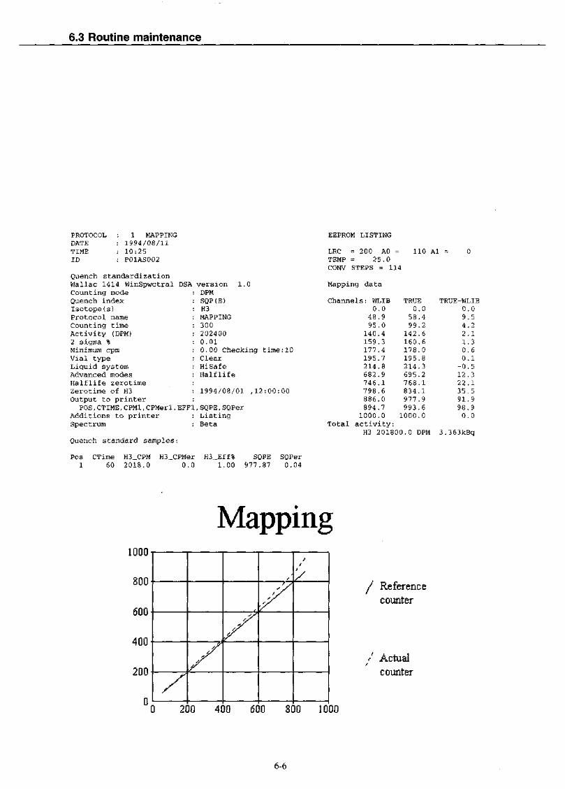
6.3 Routine maintenance
PROTOCOL : 1 MAPPINGDATE : 1994/08/11TIME : 10:25ID : P01AS002
Quench standardizationWallac 1414 WinSpwctral DSACounting modeQuench indexIsotope(s)Protocol nameCounting timeActivity (DPM)2 sigma %Minimum cpmVial typeLiquid systemAdvanced modesHalflife zerotimeZerotime of H3Output to printer
POS,CTIME,CPM1,CPMer1,EFF]Additions to printerSpectrum
Quench standard samples:
version 1.0DPMSQP(E)H3MAPPING3002024000.010.00 Checking time:10ClearHiSafeHalflife
1994/08/01 ,12:00:00
L, SQPE, SQPerListingBeta
Pos CTime H3_CPM H3_CPMer H3_Eff% SQPE SQPer1 60 2018.0 0.C) 1.00 977.87 0.04
EEPROM LISTING
LRC = 2 00 AO =TEMP = 2 5.0CONV STEPS = 114
Mapping data
Channels: WLIB0.0
48.995.0
140.4159.3177.4195.7214.8682.9746.1798.6886.0894.7
110 Al
TRUE0.0
58.499.2
142.6160.6178.0195.8214.3695.2768.1834.1977.9993.6
1000.0 1000.0Total activity:
H3 201800 .0 DPM
0
TRUE-WLIB0.09.54.22.11.30.60.1-0.512.322.135.591.998.90.0
3.363kBq
Mapping1000
800
600
400
200
0/
y
y
ffyr
/ Referencecounter
0 200 400 600 800 1000
/ Actualcounter
6-6

7 Spare parts information


1410-951-05November 1998
1409,1410,1411,1414,1415Spare Parts Catalogue
WAIIACAN COMPANY
WaIIac Oy, P.O.Box 10, FIN-20101 Turku, Finland, Tel.+358-2-2678 111, Telex 62 333wac fin,Telefax +358-2-2678357

Ordering Information
If parts are being ordered fromWallac Oy give the followinginformation on the order:
Purchase order number
Type and serial number of theinstrument for which the spare part isintended
Quantity of each item ordered
Ordering number and description(obtained from parts list)
Where the parts are to be sent
When the order is to be dispatched
Preferred mode of transport
Note: Subassemblies with an ordernumber beginning 10 84xxxx,1085xxxx or 1086xxxx are kept asstock items. It should be noted thatthese subassemblies consist ofseveral smaller parts which can beordered as separate items ifnecessary using the correspondingorder numbers.
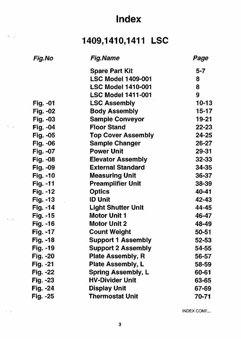
Index
1409,1410,1411 LSC
Fig. No Fig. Name Page
Fig. -01Fig. -02Fig.-03Fig.-04Fig.-05Fig.-06Fig. -07Fig.-08Fig.-09Fig.-10Fig.-11Fig.-12Fig.-13Fig.-14Fig.-15Fig.-16Fig.-17Fig.-18Fig.-19Fig.-20Fig. -21Fig.-22Fig.-23Fig. -24Fig.-25
Spare Part KitLSC Model 1409-001LSC Model 1410-001LSC ModeM 411-001LSC AssemblyBody AssemblySample ConveyorFloor StandTop Cover AssemblySample ChangerPower UnitElevator AssemblyExternal StandardMeasuring UnitPreamplifier UnitOpticsID UnitLight Shutter UnitMotor Unit 1Motor Unit 2Count WeightSupport 1 AssemblySupport 2 AssemblyPlate Assembly, RPlate Assembly, LSpring Assembly, LHV-Divider UnitDisplay UnitThermostat Unit
5-788910-1315-1719-2122-2324-2526-2729-3132-3334-3536-3738-3940-4142-4344-4546-4748-4950-5152-5354-5556-5758-5960-6163-6567-6970-71
INDEX CONT...

1415 Supplement
Fig.No Fig.Name Page
Fig. -26Fig.-27Fig. -28Fig. -29Fig. -30Fig. -31Fig. -32Fig. -33
LSC AssemblyMeasuring UnitOpticsLight Shutter UnitTop Cover AssemblyGuardHV-Divider UnitDisplay Unit
73-7980-8182-8384-8586-8788-8990-9192-93
1414 Supplement
Fig.No Fig.Name Page
Win Spectral 1414-001 95-99Alpha/Beta 1414-002 99-101Guardian 1414-003 102-104
Fig. -34 LSC Assembly 105Fig. -35 Body Assembly 107-109Fig. -36 Top Cover Assembly 110-111Fig. -37 Keybank Assembly 112-113

,1410,1411 Spare part kit 1410-20196-10-10
FOR PART
ITEM.NO
NUMBER
QTY
1410-201
ORDER NO
SPARE PART KIT
NAME
1410
TYPE
1410-201
MANUF. INF
960731
LINE
11122
222
1212
12121212
1
0.2222
22222
22222212
0 6 0
1155014110853316108564661085673010854884
1085331410854606108540211085465210857670
1085476710857671108601051085264210853857
1085902810858037108546791084979911690042
1169004411690050108552331085523510855231
1085669210853686108553131085566810855385
1176004010855243108551861085476010853794
1085768110860160108567991161102911611024
1161103211611033116110261160116911601173
1160117711601178116011791160118011550051
1155015911810160118101311181104811811047
1181105011811051118130241181303811813033
1181302511813037118110321181403711814039118130191181402811801012
SERVICE KITP.C.ASSEMBLYP.C.ASSEMBLYDCD EXPANSION KITP.C.ASSEMBLY
P.C.ASSEMPLYP.C.ASSEMBLYP.C.ASSEMBLYP. C. ASSEMBLYP.O.ASSEMBLY
P.C.ASSEMBLYP.C.ASSEMBLYP.C.ASSEMBLYP.C.ASSEMBLYP.C.ASSEMBLY
P.C.ASSEMBLYP.C.ASSEMBLYP.C.ASSEMBLYP.C.ASSEMBLYSTEPPING MOTOR
STEPPING MOTORSTEPPING MOTORP.C.ASSEMBLYP.C.ASSEMBLYP.C.ASSEMBLY
1410 OPTICS MODKITID-UNITWIRING ASS.P.C.ASSEMBLYP.C.ASSEMBLY
PHOTOMULTIPLIERP.C.ASSEMBLYP.C.ASSEMBLYP.C.ASSEMBLYP.C.ASSEMBLY
PREAMPLIFIER UNITPREAMPLIFIER UNITP.C.ASSEMBLYTRIMPOTENTIOMETERTRIMPOTENTIOMETER
TRIMPOTENTIOMETERTRIMPOTENTIOMETERTRIMPOTENTIOMETERRESISTORRESISTOR
RESISTORRESISTORRESISTORRESISTORSHIELDING BAG
INSULATIONMICROCIRCUIT TTLMICROCIRCUIT TTLMICROCIRCUIT C-MOSMICROCIRCUIT C-MOS
MICROCIRCUIT C-MOSMICROCIRCUIT C-MOSMICROCIRCUIT LINMICROCIRCUIT LINMICROCIRCUIT LIN
MICROCIRCUIT LINMICROCIRCUIT LINMICROCIRCUIT C-MOSMICROCIRCUIT CMOSMICROCIRCUIT HMOSMICROCIRCUIT LINMICROCIRCUIT CMOSTRANSISTOR NPN
590*400*260POWER SUPPLYMICRO COMPUTER
I/O BOARD
MCAMCAMOTOR CONTROL BOARDHV SUPPLYCOINCIDENCE BOARD
MCA INTERFACE 1CHSAMPLE k HOLD 1CHGAIN STABILIZERPOS. HV SUPPLYPREAMP.AND COINS.BOARD
A/D CONVERTERSAMPLE AND HOLDEXTENSION BOARDPOWER EXTENSION BOARD5V 1A 1, 8AST 0 , 4NM
12V 0,4A 1,8AST 0,26NM1,5IN 0.7A STEP ANG1.8SENSOR BOARDSENSOR BOARDSENSOR BOARD
14101205
RAMCODE READERRXA HOME SENSOR BOARD
D19MM 10DYN 12PINPOSITION SENSORCONNECTION BOARDDISPLAY (CPU)PREAMPLIFIER BOARD
1409/11 10-DYNODE1409/11/15 12-DYNODEPREAMPLIFIER BOARDIK +-10% 0,5W CERMET2K +-10% 0.5W CERMET
10K +-10% 0,5W CERMET100K +-10% 0,5W CERMET500K +-10% 0,5W CERMET470K 2% 0.5W1M 2% 0.5W
1,5M 2% 0,5W2.2M 2% 0.5W3.3M 2% 0.5W4.7M 2% 0,5W125*200
MS-PU-JKQUAD BUS/LINE DRIVERQUAD 2-INP MUXOCTAL BUS TRANSCEIVEROCTAL D-TYPE LATCH
OCTAL D-TYPE FLIP-FLOPHEX INV SCHMITT TRIGGQUAD OPER AMPL.QUAD JFET-INP OP AMPLOPERATIONAL AMPL
QUAD COMPAR.PWM CONTROL8-INP ANALOG MUX1X262144-BIT DYN RAMSERIAL COMM CONTROLLERQUAD LINE DRIVERS8X8192-BIT RAM40V 10MA0.31W
EIRIDPA 10353503DCD 10356465DCD 10356465DIC 10354883
DIA 10353517DIE 10354603HPS 10354022EPM-A 10354653LAC-A 10357727
102 0304050
60708090
100
LBR 10354766 110LAD-A 10357728 120EBU-A 10360197 130EPK 10652641 140LAB-A 150
EBZ 10359027 160EBC-A 10358036 170LPA 180
10649798 190PH265-04 200
6500-15-4-13.5 R455 2106500 R568 211RXC 10455232 220RSV 10455234 230RSZ 10455230 240
RSJ 10354300CA18RAM 10355667RXA 10455384
2 5 02 6 02 7 02 8 02 9 0
R1166-10 300RSU-A 10355242 310RSP 10455185 320HCB 10354759 330RAE 10353795 340
1045539410455394RAP 1035379567WR1K67WR2K
67XR10K67XR100K67WR500KB 1/2 BEYSCHLAGB 1/2 BEYSCHLAG
B 1/2 BEYSCHLAGB 1/2 BEYSCHLAGB 1/2 BEYSCHLAGB 1/2 BEYSCHLAGMAPOSTAT
40110N74F244NSN74LS157NPC74HCT245PPC74HCT373P
PC74HCT374PMC74HCT14ANCA 324 ETL084CNLF3 5 6N
LM 339 NTL4 94CNHCF4051BEHY51C256S-12P82530-6MC1488HM6264P-122N3904
350355360370380
390400410420430
440450460470480
490500510520530
540550560570580
590600610620630640650660

2 11800007 TRANSISTOR PNP2 11802007 TRANSISTOR FET2 11802009 TRANSISTOR FET2 11802010 TRANSISTOR FET2 11801014 TRANSISTOR NPN
2 11800009 TRANSISTOR PNP10 11830006 FUSE10 11830017 FUSE10 11830009 FUSE1 11845027 VOLTAGE SELECTOR
2 11813018 MICROCIRCUIT LIN4 11814011 OPTICAL SENSOR2 11784015 DIODE LIGHT EMITT1 10442965 SERIAL NUMBER PLAT5 11863069 P.C.CONNECTOR
4 11782023 ZENER DIODE2 11780016 DIODE2 11781006 DIODE BRIDGE2 10553597 P.C.BOARD1 11350044 COGGED BELT
1 10451435 COGGED BELT1 11350065 COGGED BELT1 11350076 COGGED BELT2 11350077 COGGED BELT1 11350048 COGGED BELT
1 11350087 COGGED BELT2 11350083 COGGED BELT2 11350097 COGGED BELT1 11350078 COGGED BELT2 10354388 GOGGED BELT WHEEL
1 11862143 CONNECTOR3 11862144 COVER3 11862132 CONNECTOR3 11862133 CONNECTOR6 11862137 COVER
3 11862130 CONNECTOR3 11862135 COVER1 11862131 CONNECTOR1 10855315 WIRING ASS.1 10555603 LABEL SET
1 11550078 DISK STORAGE BOX1 1221-244 PROGRAM PACKAGE1 10857062 SERVICE PROGRAM1 10856281 PROGRAM PACKAGE1 10856289 PROGRAM PACKAGE
1 10857813 PROGRAM PACKAGE1 10857820 PROGRAM PACKAGE1 10856296 PROGRAM PACKAGE1 10855628 PROGRAM PACKAGE1 10854502 SERVICE CONNECTOR
1 10855262 PC BOARD EXTRACTOR1 11510021 HEXAGON KEY1 11510022 HEXAGON KEY1 11550108 PLASTIC PEEL1 1410-921 JUMPER SETTINGS1 10857679 RAM EXTENSION KIT1 10457685 LOCKRING KEY
40V 10MA 0.31W40V 50MA 0.37WP-CH MOS50V 12A 75W N-CH MOS100V 18A 75W N-CH MOS60V 5A 65W DARLINGTON
60V 5A 65W DARLINGTON2.0A 2 50V SLOW 6,3*324,0A 250V SLOW 6,3*326.3A 250V SLOW 5*201X6 . 10A 250V
VOLTAGE REG 5V 1A
D3X5 585NM <100NS
2-PIN JUMPER 2A
15V 5% 17MA 1W30V 12A DUAL SCHOTTKY200V 25A1,6MM 2-P EP LKSYNCHROFLEX
BRECOFLEXBRECOFLEXSYNCHROFLEXSYNCHROFLEXSYNCHROFLEX
SYNCHROFLEXSYNCHROFLEXSYNCHROFLEXSYNCHROFLEXGRILON W 5239
5-N 24AWG5-N6-P FEMALE 24AWG6-N FEMALE 18AWGFOR 3-P CONNECTOR
8-N 24AWG8-N16-N 24AWG
3,5"ULTROTERM1205 BETAPLATE1410 SERVICE PROGRAM1410 SERVICE PROGRAM
1409 SERVICE PROGRAM1409 FIXED PROTOCOLS1410 DO MAPPING PRGDISPLAY PRG. HCB-BOARD1205
3MM4MMA4 CLEAR
DIE RAMSPRINGSTEEL T=0.7
2N39063N163BUZ 10BUZ21TIP120
TIP125193431934319195SWPO33 .1109
MC 7 805 CPOPB804MV5374C
59001
1N4744AVSK13BYV25-200RRA 1205 14706T 2,5/285
1205
6 T2,5/12010 T2,5/1606 T2.5/200
6 T2,5/3806 T2,5/50010 T2,5/65010 T2,5/13001297
CT100F24-5BTC100F-5CT156F24-6BCT156F18-6BTC156F-6
CT100F24-8BTC100F-8CT100F24-16BCA20CA20
MICROBOX 5TERMINAL EMULATOR
WITH FIXED PROTOCOLFOR HARDWARE
VI.4, VI.8, V2.0SERVICE PROGRAM
10454503
10455261NO 368NO 3 68T126/A4 0,081410-921103546031410
670680690700710
72073074 0750760
770780790800810
820830840850860
870880890900910
920930940950960
970980990
10001010
10201030104010501060
10801090111011201130
11351136114011601170
1180119012001210122012301250

PART HISTORY FROM: 91-09-25 TO: 96-10-10
FOR PART NUMBER 1410-201 SPARE PART KIT 1410 1410-201 960731
ITEM.NO QTY ORDER NO NAME TYPE MANUF. INF LINE DATE
1085473510855551108533131169004910855393
1410-9211410-92110854784108542421221-243
1155006310857820
P.C.ASSEMBLYP.C.ASSEMBLYP.C.ASSEMBLYSTEPPING MOTORPREAMPLIFIER UNIT
JUMPER SETTINGSJUMPER SETTINGSP.C.ASSEMBLYP. C. ASSEMBLYPROGRAM PACKAGE
DISK CARD BOXPROGRAM PACKAGE
COINCIDENCE BOARD LAC 10354734 100 920120SAMPLE & HOLD 1CH LAD 10354773 120 920120SAMPLE AND HOLD EBC 10353702 170 92011712V 0,4A 1,8AST 0,26NM 6500-15-4-13.5 211 9203271410 10455394 350 920120
1410 SERVICE BAG1410 SERVICE BAGGAIN STABILIZERA/D CONVERTERGEN TERM
5 1/4"1409 FIXED PROTOCOLS
1410-921 1220 9305271410-921 1220 940425EBU 10354783 130 931020EBP 10353905 160 9310111221-243 1100 931129
02177 1070 9607311136 960730

LSC Model 1409-001 1085764796-10-10
FOR PART
ITEM.NO
NUMBER
QTY
10857647
ORDER NO
LSC
NAME
1409-001
TYPE MANUF. INF
930316
LINE
10155600-3410255462-2310255462-2310255462-37
PART HISTORY
11111
111111
1085764610856730108576531085523310857618
1411-9321099004510557601104579571035761211570061
LSC ASS.DCD EXPANSION KITP.C.ASSEMBLYP.C.ASSEMBLYPROGRAM PACKAGE
INSTRUMENT MANUALQC CERTIFICATELABELSUPPORTCOVER PLATELABEL
1409/1410/1411
SW KEY MODULE BOARDSENSOR BOARDMAIN PR. 1 4 0 9 / 1 1 LSC
FOR 1 4 0 9 , 1 4 1 1
1409- AL S=0 .5ST D=16POLYCARB.0.375WALLAC 52X22,16 STICKER
10155600DCD 10356465RJG 10457652RXC 10455232WALLAC 1400 DSA
1411-93210990045
14091409
FROM: 91-09-25 TO:
405090
100110
120130
30102035
96-10-10
FOR PART
ITEM.NO
NUMBER
QTY
10857647
ORDER NO
LSC
NAME
1409-001
TYPE MANUF. INF
930813
LINE DATE
10155600-75 11570061108553931085473510855551
LABELPREAMPLIFIER UNITP.C.ASSEMBLYP.C.ASSEMBLY
WALLAC 52X22,16 STICKER 35 9303151410 10455394 60 911030COINCIDENCE BOARD LAC 10354734 70 911030SAMPLE & HOLD 1CH LAD 10354773 80 911030
LbU Mioaei
FOR PART NUMBER
ITEM.NO
10155600-3410155600-7510255462-23
PART HISTORY
QTY
11111
11118
111
FOR PART NUMBER
ITEM.NO QTY
211
1 141U-U
10857648
ORDER NO
1044654510857679108576461085527210855268
108556201410-931105556721049451211252019
105556651157006110355660
10857648
ORDER NO
108553931085473510855551
IU1
LSC
NAME
FOOTRAM EXTENSION KITLSC ASS.EXTERNAL STANDARDSTD. CAPSULE
PROGRAM PACKAGEINSTRUMENT MANUALLABELWARNING PLATERIVET
LABELLABELCOVER PLATE
LSC
NAME
PREAMPLIFIER UNITP.C.ASSEMBLYP.C.ASSEMBLY
1410-001
TYPE
PAG, BLACK, 30% GLASDIE RAM1 4 0 9 / 1 4 1 0 / 1 4 1 1
1410 LSCFOR 1410AL 9 9 . 5 S=lAL-PLATE2 . 4 * 5 . 1 AL
AL S = 0 . 5WALLAC 52X22,16STICKERPOLYCARB 0 , 3 7 5
1410-001
TYPE
1410COINCIDENCE BOARDSAMPLE & HOLD 1CH
MANUF. INF
108576489 6 - 1 0 - 1 0
920602
LINE
1215,1470 1010354603 4010155600 5010255273 6010455269 (NTL5) 70
INSTRUMENT PROGRAM 1101410-931 120NTL5 130
140TAP/D/BS 33 150
NTL5 303520
FROM: 91-09-25 TO: 96-10-10
MANUF. INF
10455394LAC 10354734LAD 10354773
920602
LINE DATE
80 91103090 911030
100 911030
8

LSG Model 1411- 1085764996-10-10
FOR PART
ITEM.NO
NUMBER
QTY
10857649
ORDER NO
LSC
NAME
1411-001
TYPE MANUF. INF
931203
LINE
10155600-3410255462-2310255462-37
1044654510857646108610911085527210856730
1085765310857618108578101411-93210990045
105556721049451211252019105576021035761611570061
FOOTLSC ASS.STD. CAPSULEEXTERNAL STANDARDDCD EXPANSION KIT
P.C.ASSEMBLYPROGRAM PACKAGEPROGRAM PACKAGEINSTRUMENT MANUALQC CERTIFICATE
LABELWARNING PLATERIVETLABELCOVER PLATELABEL
PAG, BLACK, 3 0% GLAS1409/1410/1411
SW KEY MODULE BOARDMAIN PR. 1409/11 LSCCOMM.PROTOCOLS 1409/11FOR 1409,1411
AL 99.5 S=lAL-PLATE2.4*5.1 ALAL S=0.5POLYCARB.0.375WALLAC 52*22,16 STICKER
1215,1470101556001036110110255273DCD 10356465
RJG 10457652WALLAC 140 0 DSA1409/11/151411-93210990045
NTL5
TAP/D/BS 33NTL51411
1040506070
11012 C13 0140145
150160170302035
PART HISTORY FROM: 91-09-25 TO: 96-10-10
FOR PART
ITEM.NO
NUMBER
QTY
10857649
ORDER NO
LSC
NAME
1411-001
TYPE MANUF. INF
931203
LINE DATE
10155600-75
z1111
1085768110857670108576711157006110855268
PREAMPLIFIER UNITP.C.ASSEMBLYP.C.ASSEMBLYLABELSTD.CAPSULE
1411 10455394 80 911030COINCIDENCE BOARD LAC-A 10357727 90 911030SAMPLE & HOLD 1CH LAD-A 10357728 100 911030WALLAC 52X22,16 STICKER 35 931202
10455269 50 950216
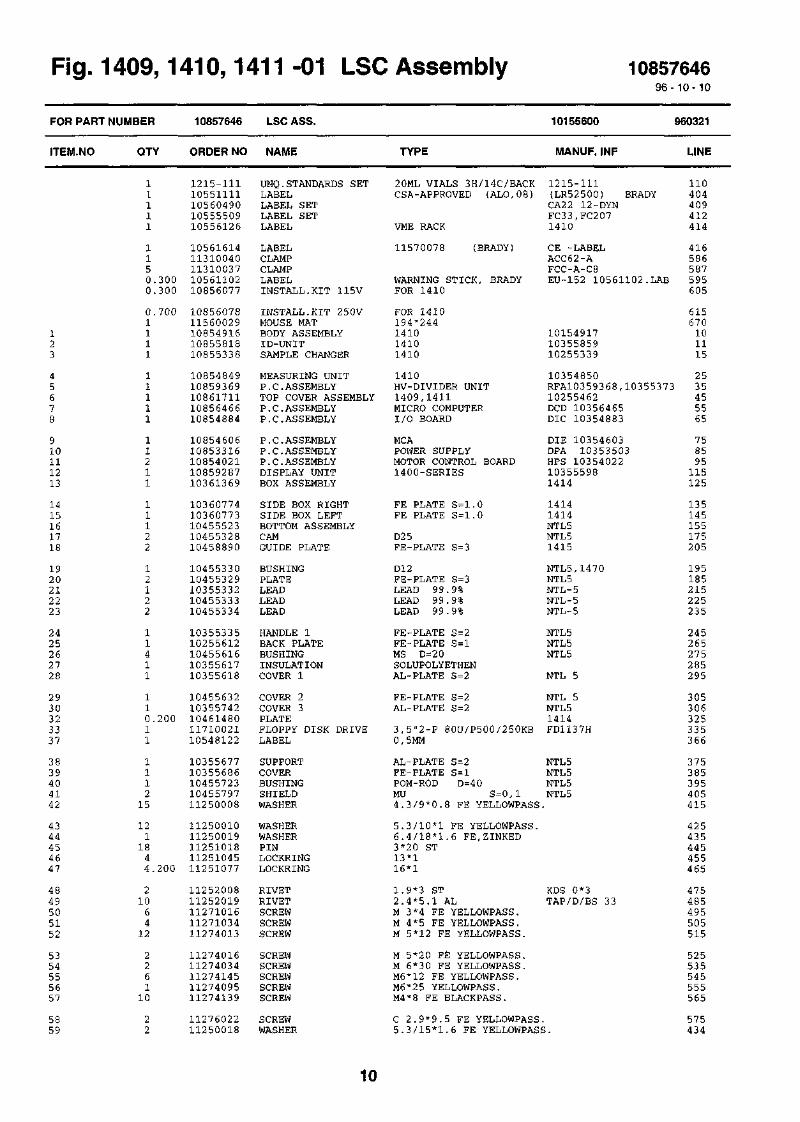
rig. i
FOR PART
ITEM.NO
123
45678
910111213
1415161718
1920212223
2425262728
2930323337
3839404142
4344454647
4849505152
5354555657
5859
i4uy, i-
NUMBER
QTY
11111
1150.3000.300
0.7001111
11111
11211
11122
12122
11411
110.20011
111215
1211844.200
21064
12
226110
22
10857646
ORDER NO
1215-11110551111105604901055550910556126
1056161411310040113100371056110210856077
1085607811560029108549161085581810855338
1085484910859369108617111085646610854884
1085460610853316108540211085928710361369
1036077410360773104555231045532810458890
1045533010455329103553321045533310455334
1035533510255612104556161035561710355618
1045563210355742104614801171002110548122
1035567710355686104557231045579711250008
1125001011250019112510181125104511251077
1125200811252019112710161127103411274013
1127401611274034112741451127409511274139
1127602211250018
m -in Lbt
LSC ASS.
NAME
UNQ.STANDARDS SETLABELLABEL SETLABEL SETLABEL
LABELCLAMPCLAMPLABELINSTALL.KIT 115V
INSTALL.KIT 2 50VMOUSE MATBODY ASSEMBLYID-UNITSAMPLE CHANGER
MEASURING UNITP.C.ASSEMBLYTOP COVER ASSEMBLYP.C.ASSEMBLYP. C. ASSEMBLY
P. C. ASSEMBLYP. C. ASSEMBLYP.C.ASSEMBLYDISPLAY UNITBOX ASSEMBLY
SIDE BOX RIGHTSIDE BOX LEFTBOTTOM ASSEMBLYCAMGUIDE PLATE
BUSHINGPLATELEADLEADLEAD
HANDLE 1BACK PLATEBUSHINGINSULATIONCOVER 1
COVER 2COVER 3PLATEFLOPPY DISK DRIVELABEL
SUPPORTCOVERBUSHINGSHIELDWASHER
WASHERWASHERPINLOCKRINGLOCKRING
RIVETRIVETSCREWSCREWSCREW
SCREWSCREWSCREWSCREWSCREW
SCREWWASHER
; Assemmy
TYPE
20ML VIALS 3H/14C/BACKCSA-APPROVED (ALO,08)
VME RACK
11570078 (BRADY)
WARNING STICK, BRADYFOR 1410
FOR 1410194*244141014101410
1410HV-DIVIDER UNIT1409,1411MICRO COMPUTERI/O BOARD
MCAPOWER SUPPLYMOTOR CONTROL BOARD1400-SERIES
FE PLATE S=l.0FE PLATE S=1.0
D25FE-PLATE S=3
D12FE-PLATE S=3LEAD 99.9%LEAD 99.9%LEAD 99.9%
FE-PLATE S=2FE-PLATE S=lMS D=20SOLUPOLYETHENAL-PLATE S=2
FE-PLATE S=2AL-PLATE S=2
3,5"2-P 80U/P500/250KB0,5MM
AL-PLATE S=2FE-PLATE S=lPOM-ROD D=40MU S=0,l4.3/9*0.8 FE YELLOWPASS.
5.3/10*1 FE YELLOWPASS.6.4/18*1.6 FE.ZINKED3*20 ST13*116*1
1.9*3 ST2.4*5.1 ALM 3*4 FE YELLOWPASS.M 4*5 FE YELLOWPASS.M 5*12 FE YELLOWPASS.
M 5*20 FE YELLOWPASS.M 6*30 FE YELLOWPASS.M6*12 FE YELLOWPASS.M6*25 YELLOWPASS.M4*8 FE BLACKPASS.
C 2.9*9.5 FE YELLOWPASS.5.3/15*1.6 FE YELLOWPASS
1085764696-
10155600
MANUF. INF
1215-111(LR52500) BRADYCA22 12-DYNFC33,FC2071410
CE -LABELACC62-AFCC-A-C8EU-152 10561102.LAB
101549171035585910255339
10354850RFA10359368,1035537310255462DCD 10356465DIC 10354883
DIE 10354603DPA 10353503HPS 10354022103555981414
14141414NTL5NTL51415
NTL5,1470NTL5NTL-5NTL-5NTL-5
NTL5NTL5NTL5
NTL 5
NTL 5NTL 51414FD1137H
NTL5NTL 5NTL 5NTL5
KDS 0*3TAP/D/BS 33
10-10
960321
LINE
110404409412414
416586587595605
615670101115
2535455565
758595115125
135145155175205
195185215225235
245265275285295
305306325335366
375385395405415
425435445455465
475485495505515
525535545555565
575434
10
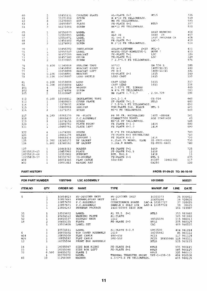
6061626364
6566676869
707 1
727 374
7 576777 879
8182101102105
112113114115116
117118119120121
122123124125126
12710355819-4310355819-4410355819-17W24W3 2
o&8812
11112
1
2X2
0,110.0.
0.0.44
0.1212
0.1211
4212.1.
111111
400
100100
100100
100
100
700800
10455131112710361127 80031045589711271095
1055607010556095105560711045618211274003
1045638210556607104572991045730011276015
1114001810458898104588991045889110458887
1035888910358888112500391127400411310047
1155011210460803112760321046096411271053
1036127010861410112741561046076210460761
1127400210461276104614141124017311240162
104616131045790310357902103557621086134610861411
COOLING PLATESCREWNUTPLATESCREW
LABELLABELLABELPLATESCREW
INSULATIONLABELBRACKETGUIDESCREW
SEALING TAPEBRACKET RIGHTBRACKET LEFTBRACKETLEAD SHIELD
LEADLEADWASHERSCREWNUT
INSULATING TAPECOVER PLATESCREWSHELTERSCREW
PB -PLATEP.C.ASSEMBLYSCREWPLATE RIGHTPLATE LEFT
SCREWHOLDERSUPPORT 1RF GASKETRF GASKET
HOLDERPLATESUPPORTID-SHIELDFLAT CABLEWIRING ASS
AL-PLATE S=3M 4"10 FE YELLOWPASS.M4 FE YELLOWPASS.FE-PLATE S=lM6*12 FE YELLOWPASS.
HVAL0,08AL S-0,8FE-PLATE T=lM 3"10 FE YELLOWPASS.
SOLUPOLYETHEN S=20WHITE-SELF-ADHESIVE-LFE-PLATE T=lFE-PLATE T=lC 2.9*6.5 FE YELLOWPASS
10*12FE S = lFE S = lFE-PLATE S=lLEAD CAST
CAST LEADCAST LEAD4.3/12*1 FE, ZINKEDM 4*6 FE YELLOWPASS.M4 PLATE 1,7-2,7
S=l,2-1,6ST-PLATE T=1.5C 3.5*6.5 FE YELLOWPASSPOM-PLATE S=8, BLACKM4*8 FE YELLOWPASS.
PB 99.6%, NICKELIZEDCONNECTION BOARDM6*16 ST YELLOWPASS.FE PLATE S=2.0FE PLATE S=2.0
M 3*6 FE YELLOWPASS.FE-PLATE S=l NICKELIZEDFE PLATE S=1.06,35x6,3 5 MONEL, GLUE3,2X4,8 MONEL
FE-PLATE T=lST-PLATE T=l,5RST. T=0,8FE-PLATE S=l40S-40S
NTL 5
NTL5
1410 WARNING1410 CR1410 PROGRAM CRLSC-5
NTL-5NOTE !LSCLSC
SM 53 0 K1409/11/151409/11/1514151415
14151415
2.54.329
CE-016NTL5
NTL 5
1400 -SERIERGE 10461408
14141414
141401-0901-660301-0901-6601
140914101410NTL 5FC207 10461300CA210
32 6510585327511
406407408410514
41141332832957 6
588400401240239
237238440513590
660640650645648
24140
546680690
700710720730740
7251213635117120
PART HISTORY FROM: 91-09-25 TO: 96-10-10
FOR PART
ITEM.NO
5
35361218
6W24W2 613
141532
42
NUMBER
QTY
12111
11121
1
1111
110.5001
10
10857646
ORDER NO
1085402310857681108576701085767110856263
1055567210494512108555971045533110555408
1055111110855461108555081085559210355564
1035556710355568104555721157007811250008
LSC ASSEMBLY
NAME
HV-DIVIDER UNITPREAMPLIFIER UNITP. C. ASSEMBLYP.C.ASSEMBLYPROGRAM PACKAGE
LABELWARNING PLATEDISPLAY UNITPLATELABEL SET
LABELTOP COVER ASSEMBLYFLAT CABLEFLAT CABLEFRONT BOX ASSEMBLY
SIDE BOX RIGHTSIDE BOX LEFTPLATE 2LABELWASHER
TYPE
HV-DIVIDER UNIT1.411COINCIDENCE BOARDSAMPLE & HOLD 1CH
10155600
MANUF. INF
1035537310455394
LAC-A 10357727LAD-A 10357728
1410/80186 BIOS ROM
AL 99.5 S=lAL-PLATE1410FE-PLATE S=3
AL-PLATE S=0.8141040S-40S50S-50S
FE-PLATE S=lFE-PLATE S=l
NTL 5
10355598NTL5CA2
LR5250010255462FC33
LINE
353 63738
106
355365115205409
40445117
FC35 10455666 118NTL5
NTL 5NTL 5NTL5
THERMAL TRANSFER PRINT THT-5-438-104.3/9*0.8 FE YELLOWPASS.
125
135145325404415
960321
DATE
93081292062592062520625
911007
911002911002940313940325940525
941214960122951128960321960115
960115960115960313950508960115
11

4347505255
11657
112114
84488
250.30020.100
1125001011251077112710161127401311274145
1127415611274139105562011127603211550112
WASHERLOCKRINGSCREWSCREWSCREW
SCREWSCREWLABELSCREWINSULATING TAPE
5.3/10*1 PE YELLOWPASS. 425 96011516*1 465 950324M 3*4 FE YELLOWPASS. 495 960115M 5*12 FE YELLOWPASS. 515 960115M6*12 FE YELLOWPASS. 545 950324
M6*16 ST YELLOWPASS. 546 960115M4*8 FE BLACKPASS. 565 960115WARNING STICK PVC ALUM EUROPIUM 152 595 950216C 3.5*6.5 FE YELLOWPASS. 650 960311S=l,2-1,6 CE-016 660 960311
12

Fig. 1409,1410,1411 -01 LSC Assembly 10155600
^

14

* » i 2 If OVObOS
TWS
'ftfcioB 3iO5ll *A
* * - L E A D OPTION
10 15 5600-B
LSC U10Piirt. 881220 QiSTark.881220 hla.Hyv. 881220 fc


1409,1410? 1411 -02 Body Assembly 1085491696-10-10
FOR PART
ITEM.NO
NUMBER
QTY
10854916
ORDER NO
BODY ASSEMBLY
NAME TYPE
10154917
W1ANUF. INF
960503
LINE
345
678910
11121314
1617181920
2122232425
2627282930
31323 33435
36373 83940
4142434445
4647484950
5154555 657
585960TR
127811
1
1111
144
1
11442
44141422
204842
21944
84111
4443
11111
124444
21112
4211
1131003711310038113100401055560110555430
1025491810160788103549211035492210354923
1035492410454925104549281035493110454932
1035493510354940104549411127502410454943
1044654511250010112500181125201211252002
1126001011274004112740121127401311274016
1127403111274136112780111127802610455004
1125000411274076108549871085550610355320
1035511311251018112500151127412611271016
1085511510855188108551871169004511690040
1127401511250001112710251127800210455327
1045593811274030114800471148004811480049
11480050114800521046205911650053
CLAMPCLAMPCLAMPLABEL SETLABEL SET
BODYBOTTOM PLATE ASS.COVER PLATE RIGHTCOVER PLATE LEFTBOX
LIDGUIDE ASSEMBLYTUBE ASSEMBLYSUPPORTBOX ASSEMBLY-
SUPPORT RIGHTSUPPORT LEFTADJUSTER NUTSCREWBRACKET ASSEMBLY
FOOTWASHERWASHERRIVETRIVET
RIVETED NUTSCREWSCREWSCREWSCREW
SCREWSCREWNUTNUTBUSHING
WASHERSCREWINSULATION SETP.C.ASSEMBLYSUPPORT
LEADPINWASHERSCREWSCREW
POWER UNITPOWER-RACKVME-RACKFANFINGER GUARD
SCREWWASHERSCREWNUTBUSHING
BRACKETSCREWFERRITE CLAMPFERRITE CLAMPFERRITE CLAMP
CLAMPFERRITE CLAMPINSULATORTRANSFORMER
AL-PLATE S=2,5AL-PLATE S=2,5AL-PLATE S=l,5
FE-PLATE S=l,5
6K14M8*60
PAG, BLACK, 3 0% GLAS5,3/10*1 FE YELLOWPASS.
FCC-A-C8ACC3 8-AACC62-AFC31CA24
NTL51414NTL5NTL5NTL5
NTL5NTL5,1470,1460NTL5,1470,1460NTL5NTL5
NTL5NTL5NTL5,1470
NTL5
1215,1470
5.3/15*1.6 FE YELLOWPASS.3.2*7.4 MONELL3.2*8.9 MONELL
M 5 2.0-3.0 MSM 4*6 FE YELLOWPASS.M 5*10 FE YELLOWPASS.M 5*12 FE YELLOWPASS.M 5*20 FE YELLOWPASS.
M 5*12 FE YELLOWPASS.M8*40 YELLOWPASS.M 8 FE YELLOWPASS.M5 NYLOCPOM BLACK D=16
A6,4 ZNM6*16 FE YELLOWPASS.11 CODES = 13 PARTSIONIZER
LEAD 99.9%3*2 0 ST
TLP/D/BS 429TLP/D/BS435
338592RIV-TI
NTL5
NTL5RRINTL5
NTL-5
8.4/17*1.6 FE YELLOWPASS.M8*35 FE YELLOWPASS.M 3*4 FE YELLOWPASS.
2 4VDC 5W 2 800RPM
M 5*16 FE YELLOWPASS.A3, 2M 3*16 FE YELLOWPASS.M3 FE YELLOWPASS.POM D3 0 BLACK
FE-PLATE S=lM 4*8 FE YELLOWPASS.D 6,6 MMD 13 MM26-WIRE FLAT CABLE
FOR 26-W. FLAT C. CLAPM40-WIRE FLAT CABLETEFLON PLATE T=l27V/4,5KV 0,45VA
10255116
43149.601-43
NTL5
NTL-5
28B2025-OAO28B2024-OAO28B2022-000
M-CLIP28B2001-000
320330340370380
1920304050
60708090
100
110120130140150
160170180190200
210220230240250
260270280290155
1652751811
161
162201171271219
121314
350360
241166218279156
151255400410420
430440157300
15

W l l -W 2 0 ,W2 3W27W30
19W 2 1 , W2
13111
1085805710855441108554421085559310856412
1410 FRAME WIREINGFLAT CABLEFLAT CABLEWIRING ASSWIRING ASS
CA 2 3 - 3 0 , SYT.26S-2*26S34S-2*34S-40S
FC31FC32CA3 6CA51
2509101716
PART HISTORY FROM: 91-09-25 TO: 96-10-10
FOR
ITEM
W272525556
PART NUMBER
.NO QTY
110.100
110.105
10854916
ORDER NO
1085559310354920115501121125200711240174
BODY ASSEMBLY
NAME
WIRING ASSBOTTOM PLATEINSULATING TAPERIVETRF GASKET SPRING
TYPE
FE-PLATE S = l , 5S = l , 2 - 1 , 6 FOR3 . 2 * 6 . 1 MONELLBeCu 2 8MM*6MM
CA3 6
PLATE
10154917
MANUF
CE-016TLP/D/BS42497-438-02
LINE
1520
310195196
960503
DATE
930512941026941027951121951121
16

Fig. 1409,1410,1411 -02 Body Assembly 10154917
17

18

\ lta sums *
10 15 4917-D
Piirt. 881201Tark. 881201Hyv 881201

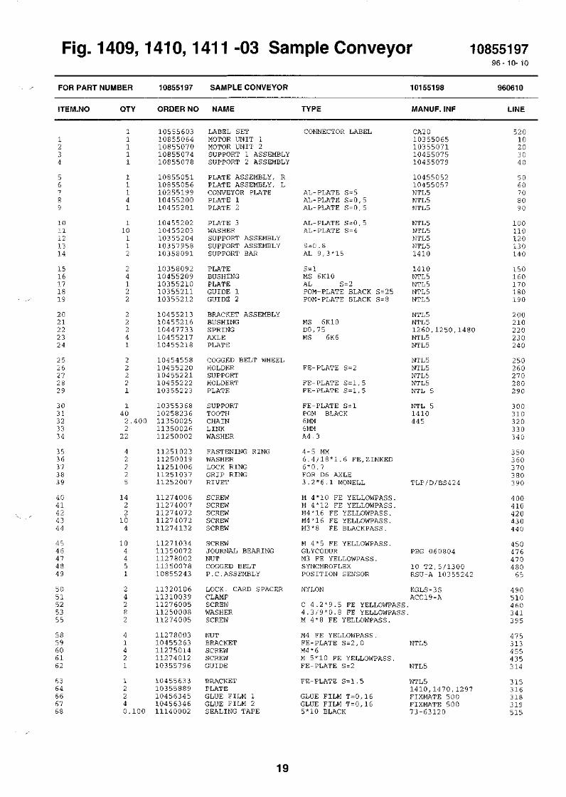
Fig. 1410, Sample Conveyor 1085519796- 10- 10
FOR PART
ITEM.NO
NUMBER
QTY
10855197
ORDER NO
SAMPLE CONVEYOR
NAME TYPE
10155198
MANUF. INF
960610
LINE
1011121314
1516'\ 11819
2021222324
2526272829
30313 23334
3536373839
4041424344
4546474849
5051525355
5859606162
6364666768
11111
11141
110112
24122
22241
22221
1402.4002
22
42225
1422104
104451
24282
41421
12240.100
1055560310855064108550701085507410855078
1085505110855056102551991045520010455201
1045520210455203103552041035795810358091
1035809210455209103552101035521110355212
1045521310455216104477331045521710455218
1045455810455220104552211045522210355223
1035536810258236113500251135002611250002
1125102311250019112510061125103711252007
1127400611274007112740721127407211274132
1127103411350072112780021135007810855243
1132010611310039112760051125000811274005
1127800310455263112750141127401210355796
1045563310355889104563451045634611140002
LABEL SETMOTOR UNIT 1MOTOR UNIT 2SUPPORT 1 ASSEMBLYSUPPORT 2 ASSEMBLY
PLATE ASSEMBLY, RPLATE ASSEMBLY, LCONVEYOR PLATEPLATE 1PLATE 2
PLATE 3WASHERSUPPORT ASSEMBLYSUPPORT ASSEMBLYSUPPORT BAR
PLATEBUSHINGPLATEGUIDE 1GUIDE 2
BRACKET ASSEMBLYBUSHINGSPRINGAXLEPLATE
COGGED BELT WHEELHOLDERSUPPORTHOLDERTPLATE
SUPPORTTOOTHCHAINLINKWASHER
FASTENING RINGWASHERLOCK RINGGRIP RINGRIVET
SCREWSCREWSCREWSCREWSCREW
SCREWJOURNAL BEARINGNUTCOGGED BELTP.C.ASSEMBLY
LOCK. CARD SPACERCLAMPSCREWWASHERSCREW
NUTBRACKETSCREWSCREWGUIDE
BRACKETPLATEGLUE FILM 1GLUE FILM 2SEALING TAPE
CONNECTOR LABEL
AL-PLATE S=5AL-PLATE S = 0, 5AL-PLATE S=0,5
AL-PLATE S = 0, 5AL-PLATE S=4
S-C.8AL 9,3*15
S-lMS 6K10AL S = 2POM-PLATE BLACK S=2 5POM-PLATE BLACK S=8
MS 6K10DO, 7 5MS 6K6
FE-PLATE S=2
FE-PLATE S = l, 5FE-PLATE S = l, 5
FE-PLATE S=lPOM BLACK6MM6MMA4,3
4-5 MM6.4/18*1.6 FE,ZINKED6*0.7FOR D6 AXLE3.2*6.1 MONELL
M 4*10 FE YELLOWPASS.M 4*12 FE YELLOWPASS.M4*16 FE YELLOWPASS.M4*16 FE YELLOWPASS.M3*8 FE BLACKPASS.
M 4*5 FE YELLOWPASS.GLYCODURM3 FE YELLOWPASS.SYNCHROFLEXPOSITION SENSOR
NYLON
C 4.2*9.5 FE YELLOWPASS4.3/9*0.8 FE YELLOWPASSM 4*8 FE YELLOWPASS.
M4 FE YELLOWPASS.FE-PLATE S=2,0M4*6M 5*10 FE YELLOWPASS.FE-PLATE S=2
FE-PLATE S=l,5
GLUE FILM T=0,16GLUE FILM T=0,165*10 BLACK
CA2 010355065103550711045507510455079
1045505210455057NTL5NTL 5NTL 5
NTL 5NTL5NTL 5NTL 51410
1410NTL 5NTL 5NTL 5NTL 5
NTL5NTL 51260,1250,1480NTL 5NTL 5
NTL 5NTL5NTL5NTL 5NTL 5
NTL 51410445
TLP/D/BS424
PBG 060804
10 T2,5/1300RSU-A 10355242
KGLS-3SACC19-A
NTL5
NTL5
NTL 51410,1470,1297FIXMATE 500FIXMATE 50073-63120
52010203040
506070809 0
10011012 0130140
150160170180190
200210220230240
250260270280290
30031032033 03 40
350360370380390
40041042043044 0
45047647048065
490510460341395
475313455435314
315316318319515
19

69WlW2W3W6, W7
11112
1129001310855299108553001085531310855315
FOOTWIRING ASS.WIRING ASS.WIRING ASS.WIRING ASS.
D12*3 ROBBER 3M SJ 5012CA16CA17CA18CA20
53061626769
PART HISTORY FROM: 91-09-25 TO: 96-10-10
FOR PART NUMBER 10855197 SAMPLE CONVEYOR 10155198 940203
ITEM.NO QTY ORDER NO NAME TYPE MANUF. INF LINE DATE
141531
2 10355207 SUPPORT BAR2 10355208 PLATE
40 10353703 TOOTH
9,3*15S = lPOM BLACK
1470,1297 140 9110181470,1297 150 9110181470,1297 310 920519
20
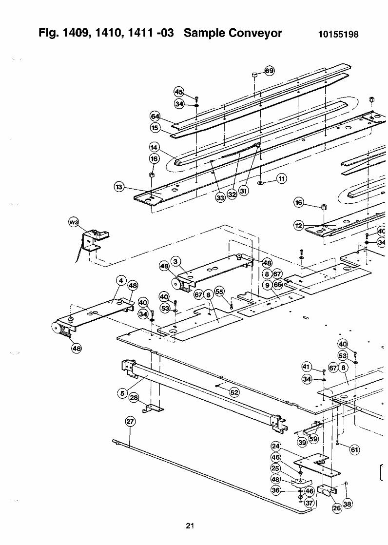
Fig. 1409,1410,1411 -03 Sample Conveyor 10155198
21

Fig. 1410,1411 -04 Floor Stand 1085602096-10- 10
FOR PART
ITEM.NO
NUMBER
QTY
10856020
ORDER NO
FLOOR STAND
NAME TYPE
10256021
MANUF. INF
890828
LINE
1
23456
7891011
1213141516
1718192021
2223242526
2728293031
323334353637
15111
14112
11444
41111
11112
11334
2122
124
43
56846
1155014311550069115500431054948410256022
1025602510356027103560301035603110456032
1045603310456034104560351045603610456037
1045603810356039103560401035604110456042
1045604310356044103560451045604710456048
1045604910356052104560531045605411350085
1131004311271093112740341127403811274023
112740241127701011276031112780031127801111260017
PACKING BOXL-LISTPACKING LISTBAGLABELBOTTOM FRAME
TOP FRAMEVERTICAL TUBESHELF 1SHELF 2SHELF 3
HANDLE 1HANDLE 2BRACKETSUPPORTING RAILSUPPORT PLATE
PINEND PLATE, RIGHTEND PLATE, LEFTSEPARATION WALLDECK
BOTTOM PLATECHEST OF DRAWERSVERTICAL RODSWINGING ARMBUSHING
PLATE ASSEMBLYBOTTOM PLATEPLATENUTWHEEL
SLIDESCREWSCREWSCREWSCREW
SCREWSCREWSCREWNUTNUTRIVETED NUT
1050*780*86090*90*25*1000MERCAPOCKET 180X140
FE-PLATE S=0.5FE-PLATE S=0.5FE-PLATE S=2,5
FE-PLATE S=0.5FE-PLATE S=0.5FE-PLATE S=2FE-PLATE S=2STAINLES PLATE S=0.8
STAINLES ROUND BAR D512MM12MM12MM18MM
15MM
FE-AUTOM.STEEL D22
AL-PLATE S=3FE-PLATE S=36K19
M4*6 FE YELLOWPASS.M6*30 FE YELLOWPASS.M8*16 FE YELLOWPASS.M8*30 FE YELLOWPASS.
M8*40 FE YELLOWPASS.M8*3 5 FE YELLOWPASS.3,5*13 YELLOWPASS.M4 FE YELLOWPASS.M8 FE YELLOWPASS.M5 1.0-2.0 MS
VIKEX6311-01C6WALLACNTL5
NTL5NTL5BLACK NTL5BLACK NTL5NTL5
NTL5NTL5NTL5NTL5NTL5
NTL5NTL5NTL5NTL5NTL5
NTL5NTL5NTL5NTL5NTL5
NTL5NTL5NTL5NTL5ESL-J-75ND/K
BS 230E6500
SFS 2458HECO-FIX
338591RIV-TI
40041042043010
2030405060
708090
100110
120130140150160
170180190200210
220230240250260
270280290300310
320330340350360361
22

HZ 191? 910627 *4HE 2122 9^0511 A!IE 2.151 9M0S11 t&HE 1199 9fOHt «
10 15 5198-A
Piirt. 881124Tark.881124Hyv 881124


toCO
10 25 6021
Piirt.881213 TusTark.881213 IVa.Hyv 881213 £•/
Tj
oCO
o
OO
eg3Q.
orotnenoN5
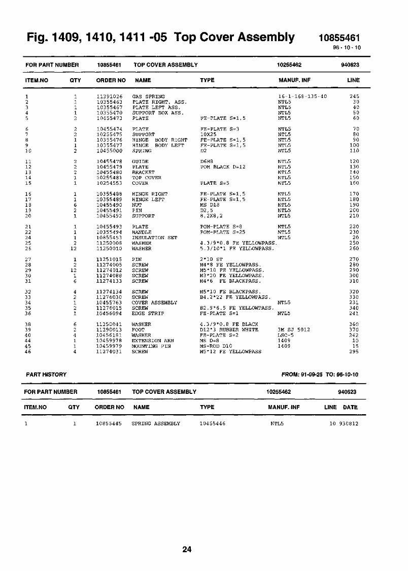
Fig. 1410, -05 Top Cover Assembly 108554619 6 - 1 0 - 10
FOR
ITEM
12345
678910
1112131415
1617181920
2122242526
2728293031
3233343536
383940444546
PART NUMBER
I.NO QTY
11112
22112
22211
11621
111212
121216
42121
624114
PART HISTORY
FOR
ITEM
PART NUMBER
.NO QTY
10855461
ORDER NO
1139102610355463103554671035547010455473
1045547410255475103554761035547710455000
1045547810455479104554801025548110254553
1035548810355489104554901045549110455492
1045549310355494108554531125000811250010
1125101511274005112740121127408811274133
1127413411276030104557631127601510456094
112500411129001310456181104599781045997911274031
10855461
ORDER NO
TOP COVER ASSEMBLY
NAME
GAS SPRINGPLATE RIGHT, ASS.PLATE LEFT ASS.SUPPORT BOX ASS.PLATE
PLATESUPPORTHINGE BODY RIGHTHINGE BODY LEFTSPRING
GUIDEPLATEBRACKETTOP COVERCOVER
HINGE RIGHTHINGE LEFTNUTPINSUPPORT
PLATEHANDLEINSULATION SETWASHERWASHER
PINSCREWSCREWSCREWSCREW
SCREWSCREWCOVER ASSEMBLYSCREWEDGE STRIP
WASHERFOOTWASHEREXTENSION ARMMOUNTING PINSCREW
TOP COVER ASSEMBLY
NAME
TYPE
FE-PLATE S=l,5
FE-PLATE S=310X2 5FE-PLATE S=l,5FE-PLATE S=l,5D2
D6H8POM BLACK D=12
PLATE S=5
FE-PLATE S = l, 5FE-PLATE S = l, 5MS D18D2,58,2X8,2
POM-PLATE S=8POM-PLATE S=2 5
4.3/9*0.8 FE YELLOWPASS5.3/10*1 FE YELLOWPASS.
2*10 STM4*8 FE YELLOWPASS.M5*10 FE YELLOWPASS.M3*20 FE YELLOWPASS.M4*6 FE BLACKPASS.
M5*10 FE BLACKPASS.B4.2*22 FE YELLOWPASS.
B2.9*6.5 FE YELLOWPASS.FE-PLATE S=l
4.3/9*0.8 FE BLACKD12*3 RUBBER WHITEFE-PLATE S=2MS D=8MS-ROD D10M5*12 FE YELLOWPASS
10255462
MANUF. INF
16-1-168-135NTL5NTL5NTL5NTL5
NTL5NTL5NTL5NTL5NTL5
NTL5NTL5NTL5NTL5NTL5
NTL5NTL5NTL5NTL5NTL5
NTL5NTL5NTL5
NTL5
NTL5
3M SJ 5012LSC-514091409
940623
LINE
-40 24530405060
708090100110
120130140150160
170180190200210
22023020
250260
270280290300310
320330231340241
3603702421015
295
FROM: 91-09-25 TO: 96-10-10
10255462
TYPE MANUF. INF
940623
LINE DATE
10855445 SPRING ASSEMBLY 10455446 NTL5 10 930812
24
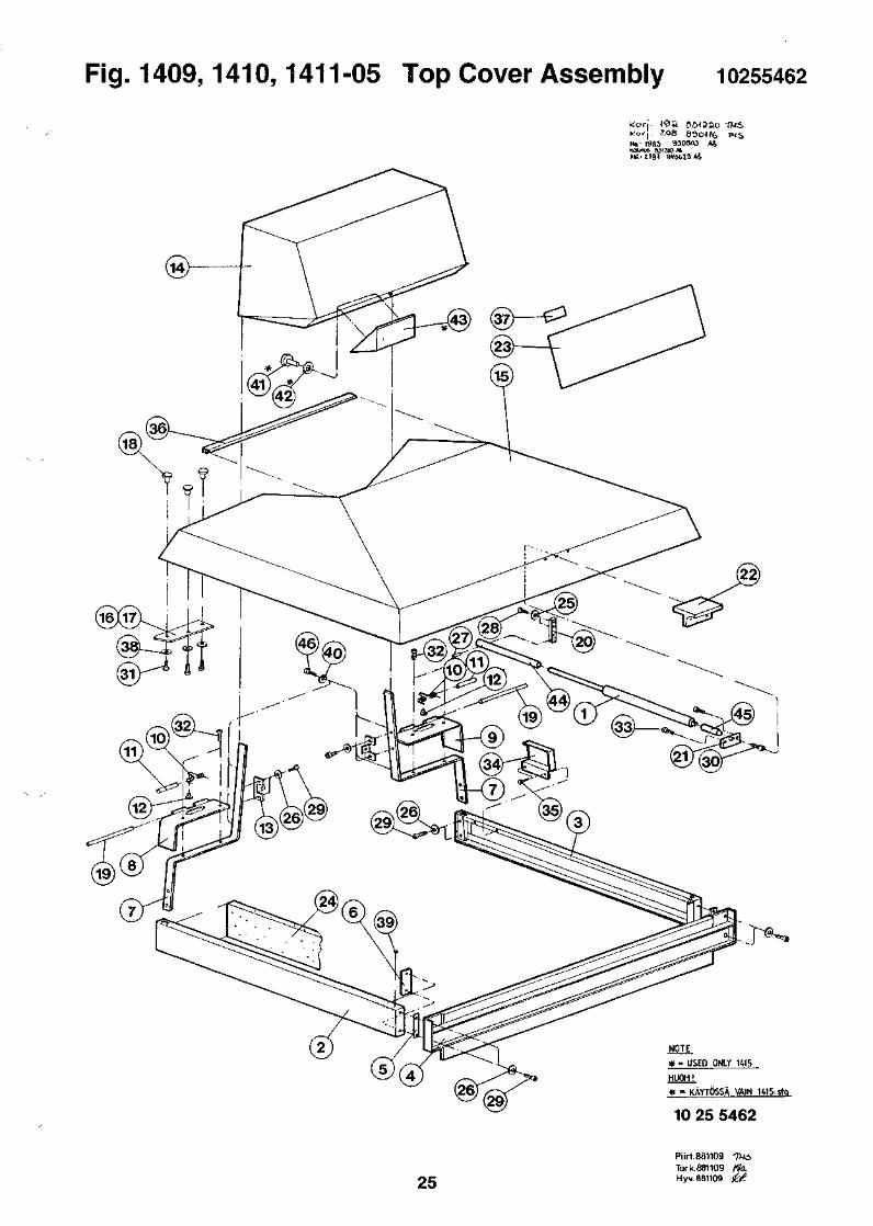
Fig. 1409,1410,1411-05 Top Cover Assembly 10255462
kori. <<aa seiaaoKorj. 208 690<(feHE:1983 9305O3 A4KOUAS S21Z3M
USED ONLY 1«5
HUOM!
* - KAYTOSSA VAIN U15.stg
10 25 5462
25
Piirt.861109 TUi,Tark.881109 / to.Hyv. 881109 &£

Fig. 1409,1410,1411 -06 Sample Changer 108553389 6 - 1 0 - 10
FOR PART NUMBER 10855338 SAMPLE CHANGER 10255339 910603
ITEM.NO QTY ORDER NO NAME TYPE MANUF. INF LINE
124
112
108551971085485711274031
SAMPLE CONVEYORELEVATOR ASSEMBLYSCREW
14101410M5*12 FE YELLOWPASS.
1015519810254858
102040
26

Fig. 1409,1410,1411 -06 Sample Changer 10255339
H
27

28

ng.
FOR PART
ITEM.NO
1
23456
7891011
1213141516
1718192021
2223242526
2728293031
3233343536
3738394041
4243444546
4748495051
52ClC2,3DlFl,2
F3Kl, K2LIRlSI
S2TR1
I4uy,i
NUMBER
QTY
1620.2502
11111
11111
41133
11442
44416
2
624
22224
28392
21141
71010.260
10
0.0961212
12111
11
I41U, 1
10855115
ORDER NO
1055570911310013118621371145001710850578
1085057710853848102551171035511810355119
1045512010455121103551221035512310455124
1045483611730016118700481188002511880027
1055500210548240112500011125000211250004
1125000611250010112500211125001211260016
1126001011270001118621271127102111271025
1127104811271054112740091127401511274072
1127601011278002112780031127800411278006
1186103611861028113100401186100311250008
1146000911274012104614241124017311252007
1124017411626007116300361178100611830006
1183002011862133116500631160117311845021
1184502711650066
411 -U/ HO1
POWER UNIT
NAME
LABEL SETWIRE TIECOVERWRAPPING SPIRALCONNECTION BOARD
CONNECTION BOARDP.C.BOARDBODY PLATECOVER PLATEBOX
SEALSEALPLATECOVERSLIDE
NUTACCU PACKCONNECTOR STRIPFUSE HOLDERFUSE CAP
LABELLABELWASHERWASHERWASHER
WASHERWASHERSERRAT LOCK WASHERWASHERRIVETED NUT
RIVETED NUTSCREWLOCKING NUT ASSYSCREWSCREW
SCREWSCREWSCREWSCREWSCREW
SCREWNUTNUTNUTNUT
CABLE LUGCABLE LUGCLAMPFLAT CONNECTORWASHER
SOLDERING TAGSCREWSLIDERF GASKETRIVET
RF GASKET SPRINGCAPACITOR H.V.CAPACITOR ELECTRDIODE BRIDGEFUSE
FUSECONNECTORMAINS FILTER-CONNRESISTORROCKER SWITCH
VOLTAGE SELECTORTRANSFORMER
wer unit
TYPE
2.4*102 NYLON 66FOR 3-P CONNECTOR12 MM1230
1230CONNECTION BOARDAL-PLATE S=3AL-PLATE S=2FE-PLATE S=l
PRESPAN S=0,5PZ-940AL S = 3FE-PLATE S=lPVC S=8
MS 6K612V 4AH NICD3-P 2,5MM216A 250VFUSE , 6,3X32MM
POLYETHEN1215/16A3, 2A4, 3A6 ,4 ZN
3.2/7*0.5 FE YELLOWPASS5.3/10*1 FE YELLOWPASS.3.0 ANNEALED ZINKEDM6 CUM 4 1.0-2.0 MS
M 5 2.0-3.0 MSM 6*25 CUD-CONN. L7,l 4-40NC-2BM 3*10 FE YELLOWPASS.M 3*16 FE YELLOWPASS.
M 3*10 FE YELLOWPASS.M 4*10 FE YELLOWPASS.M 4*2 0 FE YESLLOWPASS.M 5*16 FE YELLOWPASS.M4*16 FE YELLOWPASS.
C 2.9*13 FE YELLOWPASS.M3 FE YELLOWPASS.M4 FE YELLOWPASS.M5 FE YELLOWPASS.M 6 CU
M4 0,75-l,5MM2M6 0.75-1.5MM2
6,3X0,8MM 0.75-1.5MM24.3/9*0.8 FE YELLOWPASS
D10/6*10M 5*10 FE YELLOWPASS.AL 8X3 06,3 5x6,3 5 MONEL, GLUE3.2*6.1 MONELL
BeCu 2 8MM*6MM47NF 20% 2 50VAC 1KVDC10000UF -10i-30% 40V200V 25A2.0A 250V SLOW 6,3*32
15A 32V FAST 6,3X326-N FEMALE 18AWG250V 6A 3-N1M 2% 0.5W2X2 10A 250V
1X6 5-TENSION 10A 250V288VA
1085511596-
10255116
MANUF. INF
SST1MPANDUITTC156F-6PLIOSPIRE 12MMRPC 10650579
RPD 10650580'RPZNTL5NTL5NTL5
NTL5
NTL5NTL5NTL5
NTL510X NC10VR4321/BDS/03FEU 031.1673FEK 031.1661
1205 ACCUWALLAC
3 .2*5.5*0.45
336493RIV-TI
338592RIV-TI
17D20418-2
A 1543 RA1565RACC62-AA 1507 FL
A2004 ME
1400 -SERIE POWER U01-0901-6603TLP/D/BS424
97-438-02PME275ME5470M RIFAPEH179KD5100QB2BYV25-20019343
AGC-15CT156F18-6BFN321-6/01B 1/2 BEYSCHLAGA14 50VA
SWPO3 3 .1109
10- 10
960112
LINE
12156058059010
2030405060
708090100110
120220230240250
260270280290300
310320330340350
360370380390400
410420430440450
46047 0480490500
510520550530311
540441610600630
62013 0140160200
210570190150170
18012 5
29

PART HISTORY FROM: 93-09-22 TO: 96-10-10
FOR
ITEM
1148405251
PART NUMBER
.NO QTY
2870.105
11
10855115
ORDER NO
1045512411274012112780041124017411252007
POWER UNIT
NAME
SLIDESCREWNUTRF GASKET SPRINGRIVET
TYPE
PVC-PLATE S=8M 5*10 FE YELLOWPASS.M5 FE YELLOWPASS.BeCu 2 8MM*6MM3 . 2 * 6 . 1 MONELL
10255116
MANUF. INF
NTL5
97-438-02TLP/D/BS424
LINE
110441490620630
960112
DATE
950920950920950920960111960111
30
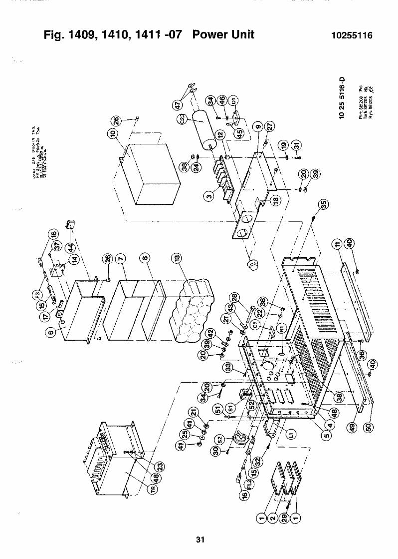
Fig. 1409,1410,1411 -07 Power Unit 10255116
o
CM
31

Fig. 1409,1410,1411 -08 Elevator Assembly 1085485796-10-10
FOR PART
ITEM.NO
12467
89101112
1415161718
1920212324
2526272930
3132333435
3637383940
4142434445
45KM
NUMBER
QTY
13111
11111
11421
22214
44642
0.6001442
11111
12212
111
PART HISTORY
FOR PART
ITEM.NO
NUMBER
QTY
10854857
ORDER NO
1025485910454860104548621045486410454865
1045486610454867103574821035438810454873
1045487510454876113500981045487810454879
1045488010454881112500081125200711274004
1127400511274007112740121127502111276015
1135002511350044113500721135007310454882
1055359710855186104561621045616410456163
1045616111251055112710351139101210461476
112510421186308911690042
10854857
ORDER NO
ELEVATOR ASSEMBLY
NAME
BODYGUIDE PIECEGUIDEBRACKETSPRING
BRACKETPLATECOGGED BELT WHEELGOGGED BELT WHEELLIFT ARM
PLATEAXLECOG WHEELPLATEBUSHING
PINBUSHINGWASHERRIVETSCREW
SCREWSCREWSCREWSCREWSCREW
CHAINCOGGED BELTJOURNAL BEARINGJOURNAL BEARINGAXLE
P.C.BOARDP.C.ASSEMBLYBUSHINGAXELPLATE
BUSHINGPINSCREWBREAK SPRINGJOURNAL BEARING
PINP.C.CONNECTORSTEPPING MOTOR
ELEVATOR ASSEMBLY
TYPE
AL S = 3AL 10X25POM BLACK S=20FE S=l,5SPRINGBRONZE S=0,5
FE S=2,5FE S=2Z 28GRILON W 523 9
FE S=l,5D6H8Z10ROSTPROOF PLATE S=0.8MS D8/6
SPRINGBRONZE 1,7X16POM BLACK D=84.3/9*0.8 FE YELLOWPASS3.2*6.1 MONELLM 4*6 FE YELLOWPASS.
M 4*8 FE YELLOWPASS.M 4*12 FE YELLOWPASS.M 5*10 FE YELLOWPASS.M4*4 AISI316C 2.9*6.5 FE YELLOWPASS
6MMSYNCHROFLEXGLYCODURGLYCODURDD6H8
1,6MM 2-P EP LKCONNECTION BOARDBRASS ROUND BAR D30STAINLES BAR D6FE-PLATE S=l
BRASS ROUND BAR D82*10 ROSTPROOFM 4*8 FE YELLOWPASS.0.5*5*3 0 ROSTPROOF6/9x10
2*85-P STRAIGHT LOCKABLE5V 1A 1,8AST 0,4NM
10254858
MANUF. INF
NTL5NTL5NTL5NTL5NTL5
NTL51409,1235,1297NTL-51297NTL5
NTL5NTL5S6-10NTL5NTL5
NTL5NTL5
TLP/D/BS424
4456T 2,5/285PBG 060804 FPG 060810 F
951025
LINE
1020406070
809010011012 0
140155160170180
190200210230240
250260270290300
310320330340150
RRA 1205 1470 201RSP 10455185 202NTL5NTL5NTL5
NTL5
MLSS100-5BPH265-04
FROM: 91-09-25 TO:
10254858
NAME TYPE MANUF. INF LINE
203204205
206238239341208
235350360
96-10-10
951025
DATE
511161334
11418
1045486310357481104548771045487411350073
PLATECOGGED BELT WHEELCOGWHEELLIFT ARM HEADJOURNAL BEARING
FE-PLATE S=l,5 NTL5Z 28 NTL5S6-10 NTL5STAINLESS STEEL D6h8 NTL5GLYCODUR PG 060810 F
50 920406110 920403160 911212130 950608340 951024
32

Fig. 1409,1410,1411 -08 Elevator Assembly 10254858
COU)00*tmCM
o
*
ait
tooz
!^ JH jP
Piir
t 8J
Tar
k.8{
Hvv
8!
33

Fig. ,1410, -09 External Standard 1085527296 -10 -10
FOR PART NUMBER
ITEM.NO
23457
89101 112
1314151617
1819202122
2324262728
293 1323334
3 536373839
404 1424344
4 546474849
50KM
QTY
21111
22111
12211
11121
21211
0 .9504323
4224
16
64142
22121
111
PART HISTORY
FOR PART NUMBER
ITEM.NO QTY
10855272
ORDER NO
1085523310355274104548661045486710455276
1045527710455278104550621045527910455280
1045506310455281104552821045528310455284
1045528510452652104552861045528710455288
1045528910355290104552921046109910553597
1118303111250006112500081125001911250039
1125103111252008112600211127101611274004
1127400711274015112740721127500811274095
1135002711350080105561581125000410457125
104605711186308911690042
10855272
ORDER NO
EXTERNAL STANDARD
NAME
P . C. ASSEMBLYBODYBRACKETPLATELOCKING RING
PLATE 1PLATE 2WHEEL 1BUSHINGAXLE 1
WHEEL 2AXLE 2BEARINGGUIDE 1GUIDE 2
LATHSPRINGTUBEBUSHINGSPRING
BRACKETLEAD SHIELDPLATELABELP.C.BOARD
TUBEWASHERWASHERWASHERWASHER
FASTENING RINGRIVETPLUG NUTSCREWSCREW
SCREWSCREWSCREWSCREWSCREW
BEARINGJOURNAL BEARINGLABELWASHERBUSHING
SPRINGP.C.CONNECTORSTEPPING MOTOR
EXTERNAL STANDARD
NAME
TYPE
SENSOR BOARDAL-PLATE S=5FE-PLATE S = 2 , 5FE-PLATE S=2MS D20
FE-PLATE S = 2 , 5FE-PLATE S = 2 , 5URETHANMS-ROD D18D8H7
URETHAND6H8POMAL 10X2 5AL 10X25
FE S = lD = l , 5ACID-PROOF TUBE D6/4MS-ROD D20SPRINGBRONZE S = 0 , 5
FE S = l , 5LEAD 99,9%AL 10X20AL S = l1,6MM 2-P EP LK
D=6/4 POLYAMID3 . 2 / 7 * 0 . 5 FE YELLOWPASS4 . 3 / 9 * 0 . 8 FE YELLOWPASS6 . 4 / 1 8 * 1 . 6 FE,ZINKED4 . 3 / 1 2 * 1 FE, ZINKED
FOR 5-7 MM AXLE1.9*3 STM6*l l ST SINK.M 3*4 FE YELLOWPASS.M 4*6 FE YELLOWPASS.
M 4*12 FE YELLOWPASS.M 5*16 FE YELLOWPASS.M4*16 FE YELLOWPASS.M4*6 AISI316M6*25 YELLOWPASS.
D 6 / 1 0 - 9GLYCODURWHITE SELF-FASTENINGA 6 , 4 ZNPOM
SPRINGBRONZE S = 0 , 35 - P STRAIGHT LOCKABLE5V 1A 1,8AST 0.4NM
TYPE
10255273
MANUF. INF
RXC 10455232NTL-5NTL51409 ,1235 ,1297NTL-5
NTL-5NTL-587 SHORE ANTL-5NTL-5
87 SHORE A
NTL-5NTL-5NTL-5
NTL-51220
NTL-5NTL 5
NTL-5NTL-5NTL-51400-SERIESRRA 1205
6*1 PA 11
KDS 0*3LA6
HK0609PBG 081005.5F1410
1410
NTL 5MLSS100-5BPH265-04
FROM: 91-09-25
10255273
MANUF. INF
941216
LINE
2030405070
8090
1 0 01101 2 0
1301 4 01 5 0160170
1 8 01 9 02 0 02 1 02 2 0
2 3 02 4 02 6 02 7 0
1470 280
2 9 03103 2 03 3 03 4 0
3 5 03 6 03 7 03 8 03 9 0
4 0 04 1 04 2 04 3 04 4 0
4 5 04 6 02 7 1309201
225490480
TO: 96-10-10
941216
LINE DATE
62227
111
104552751045528810455310
PLATESPRINGLABEL
FE-PLATE S=2 ,0SPRING PRONZE S=0AL-PLATE S=l
. 5NTL5NTL 5NTL 5
602202 7 0
930115940510941215
34

Fig. 1409,1410,1411 -09 External Standard 10255273
CO
CMIOU)CM
OT"
in "2 £
"C -^
35
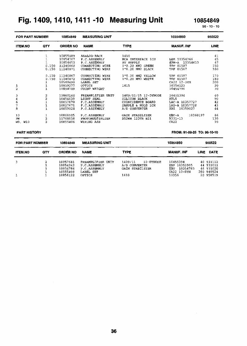
i-ig. 14uy, i
FOR PART NUMBER
ITEM.NO
12
34678
10PMW9, W10
PART HISTORY
QTY
1110.1500.150
0.1500.150111
22111
122
FOR PART NUMBER
ITEM.NO
3
1
QTY
21111
41U, 1
10854849
ORDER NO
1085518910854767108546521124006811240071
1124006711240072105604901085927710854789
1086016010454039108576701085767110859028
108601051176003810855406
10854849
ORDER NO
1085768110854242108547841055540810856122
411 -1U M(
MEASURING UNIT
NAME
ANALOG-RACKP.C.ASSEMBLYP.C.ASSEMBLYCONNECTING WIRECONNECTING WIRE
CONNECTING WIRECONNECTING WIRELABEL SETOPTICSCOUNT WEIGHT
PREAMPLIFIER UNITLIGHT SEALP.C.ASSEMBLYP.C.ASSEMBLYP.C.ASSEMBLY
P. C. ASSEMBLYPHOTOMULTIPLIERWIRING ASS
MEASURING UNIT
NAME
PREAMPLIFIER UNITP.C.ASSEMBLYP.C.ASSEMBLYLABEL SETOPTICS
;asurmg unit
TYPE
1410MCA INTERFACE 1CHHV SUPPLY1*0.2 0 MM2 GREEN1*0.20 MM2 BLACK
1*0.20 MM2 YELLOW1*0.20 MM2 WHITE
1415
1 4 0 9 / 1 1 / 1 5 12-DYNODESILICON BLACKCOINCIDENCE BOARDSAMPLE & HOLD 1CHA/D CONVERTER
GAIN STABILIZERD52MM 12DYN B21
TYPE
1409 /11 10-DYNODEA/D CONVERTERGAIN STABILIZER
1410
10354850
MANUF. INF
1085484996-10- 10
950522
LINE
41LBR 10354766 45EPM-A 10354653 47TPF 01507 150TPF 01507 160
TPF 01507TPF 01507CA22 12-DYN1035612310454790
170180200
2030
10455394 40NTL5 90LAC-A 10357727 42LAD-A 10357728 43EBZ 10359027 44
EBU-A 10360197 46R331-13 130CA22 10
FROM: 91-09-:
10354850
MANUF. INF
25 TO: 96-10-10
950522
LINE DATE
10455394 40 931112EBP 10353905 44 931011EBU 10354783 46 931020CA22 10-DYN 200 94052410356 20 950519
36
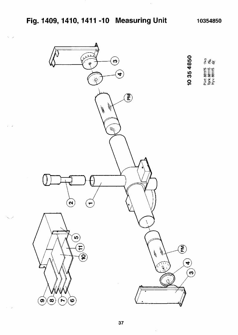
Fig. 1409,1410,1411 -10 Measuring Unit 10354850
oiooo
CO
ooo co coCO CO CO
37

i-ig. 141U-
FOR PART NUMBER
ITEM.NO
12345
678910
1112131415
16C37R77-83
QTY
11141
21145
23120.400
217
1 1 KT
10857681
ORDER NO
1085766910355395103553971045539810455399
1045540010455401105445761127104411271045
1127102111278002113100061125101411241001
112500011162002711603501
eampimer i
PREAMPLIFIER UNIT
NAME
P.C.ASSEMBLYBOX ASSEMBLYCOVERNUTINSULATION
SPRINGTIONBASELABELSCREWSCREW
SCREWNUTCLAMPPINGROUNDING BRAID
WASHERCAPACITOR ELECTRRESISTOR MF
jmt
10-DYNODE
TYPE
PREAMPLIFIER BOARD
FE-PLATE S=l6K6PRESPAN-PLATE S=0 ,5
GERMAN SILVER S=0,15BASE HAMAMATSUWARNING LABELM3*4 FE YELLOWPASS.M3*5 FE YELLOWPASS.
M3*10 FE YELLOWPASS.M3 FE YELLOWPASS.MS 1.25 MKL1*5 STD2,4 MONEL
A3,2 YELLOWPASS.INF -20+50% 500V1M 1% 0.25W 50PPM
10455394
MANUF. INF
108576819 6 - 1 0 - 10
940831
LINE
RAG-A 10357726 10NTL5 30NTL5 40NTL5 50NTL5 60
NTL 5 70E678-21A NTL5 80DANGER H.V. SERIVA 9 0
100110
A 3024 ASA
MR111
120130140150160
170221265703102 27411-2 VITROHM 23
pig.
FOR PART
ITEM.NO
2345
678910
1112131415
161718C37,41R77-86
1409, 1
NUMBER
QTY
11141
21145
21220.400
4222
10
PART HISTORY
FOR PART
ITEM.NO
11121316
NUMBER
QTY
2312
1411 -1
10860160
ORDER NO
1086015910355395103553971045539810455399
1045540010455401105445761127104411271045
1127101911278002113100061125101411241001
1125000111271017112600351162002711603501
10860160
ORDER NO
11271021112780021131000611250001
l Hreampi
PREAMPLIFIER UNIT
NAME
P.C.ASSEMBLYBOX ASSEMBLYCOVERNUTINSULATION
SPRINGTIONBASELABELSCREWSCREW
SCREWNUTCLAMPPINGROUNDING BRAID
WASHERSCREWRISE PINCAPACITOR ELECTRRESISTOR MF
PREAMPLIFIER UNIT
NAME
SCREWNUTCLAMPWASHER
iner unit
12-DYNODE
TYPE
PREAMPLIFIER BOARD
FE-PLATE S=lMS 6K6PRESPAN S=0,5
S=0,15
M 3*4 FE YELLOWPASS.M 3*5 FE YELLOWPASS.
M 3*8 FE YELLOWPASS.M3 FE YELLOWPASS.MS 1.25 MKL1*5 STD2,4 MONEL
A3, 2M 3*5 MSM3*10 MSINF -20+50% 500V1M 1% 0.25W 50PPM
12-DYNODE
TYPE
M 3*10 FE YELLOWPASS.M3 FE YELLOWPASS.MS 1.25 MKLA3, 2
1086016096
10455394
MANUF. INF
RAS 10360158NTL 5NTL 5NTL 5NTL-5
NTL 5E678-21A NTL5DANGER H.V. SERIVA
A 3024 ASA
MR111
KTS.112710795 . 0 3 . 1 0 3221265703102411-2 VITROHM
- 1 0 - 1 0
960103
LINE
1030405060
708090
100110
120130140150160
170180190
2723
FROM: 91-09-25 TO: 96-10-10
10455394
MANUF. INF LINE
120130
A 3024 ASA 140170
960103
DATE
960102960102960102960102
38

Fig. 1409,1410,1411 -11 Preamplifier Unit 10455394
39

Fig. 1409,1410,1411 -12 Optics
91011
121314D1,D2
1 10854822 LIGHT SHUTTER UNIT1 10354851 BODY2 10256157 REFLECTOR2 10457768 RING2 10454853 TUBE
1 10454854 BOX 11 10454855 BOX 26 11271045 SCREW2 10556418 P.C.BOARD2 11271107 SCREW
2 11278017 NUT2 11460001 SOLDERING TAG4 11250042 WASHER2 11784015 DIODE LIGHT EMITT
1085612296-10- 10
FOR PART
ITEM.NO
NUMBER
QTY
10856122
ORDER NO
OPTICS
NAME TYPE
10356123
MANUF. INF
930916
LINE
ULTEM 1000POM, BLACKCU-TUBE D=57/52
AL-PLATE S=lAL-PLATE S=lM3*5 FE YELLOWPASS.1,6MM 1-P EPM2.5*6 MS NICKEL
M2.5 FE YELLOWPASS.D 5.5/3.5*82.7/5*0.5 ACID-PROOF.D3X5 YELLOW 585NM <100NS
10354823NTL5NTL51410NTL5
NTL5NTL5
RXI
A2021 ME
MV5374C
1020305060
708090
1 1 0120
1 3 01 4 0150100
40
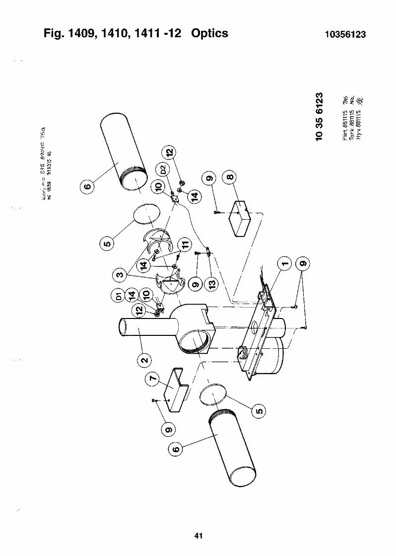
Fig. 1409,1410,1411 -12 Optics 10356123
I
fV)it- °
COCM
CDinCO
41

i-ig.
FOR PART
ITEM.NO
1234
56789
1011121314
1516181920
2122232425
2627282930
3132333435
3638394041
42KM
i4uy, i
NUMBER
QTY
11111
11424
11112
130.01511
31131
12421
17121
23211
111
I41U, 1
10855818
ORDER NO
1055537510855668103557341045573210455733
1045572510455724112900241045573111252033
1045572610455728104557501035438810455727
1055359711290019111860061135004811250006
1125000810455899112710161127101811271023
1127102611271034112710361127107511274001
1127401511275003113100311139003410456132
1125001911278002112780041127502510457147
104494281186308911690044
411 -13 ID
ID UNIT
NAME
LABEL SETP. C. ASSEMBLYID-BODYPIECESUPPORT PIECE
LOWERPIECEUPPERPIECEBUSHINGGUIDERIVET
SLEDGEPLATE1FILL PIECEGOGGED BELT WHEELAXLE
P.C.BOARDBUSHINGSHRINKABLE TUBINGCOGGED BELTWASHER
WASHERBASEPIECESCREWSCREWSCREW
SCREWSCREWSCREWSCREWSCREW
SCREWSCREWCLAMPO-RINGADJUST PART
WASHERNUTNUTSCREWPIN
SPRINGP.C.CONNECTORSTEPPING MOTOR
unit
TYPE
CONNECTOR LABEL PAPERRAMCODE READERFE-PLATE S=l,5AL-PLATE S=5AL 15*20
ALALD3,4/6*7AL3*12 A2
POM ,BLACKAL6T 2,5/950GRILON W 5239D3
1,6MM 2-P EP LKD3,4/6*51/4" CLEARSYNCHROFLEX3.2/7*0.5 FE YELLOWPASS
4.3/9*0.8 FE YELLOWPASSFE-PLATE S=3M 3*4 FE YELLOWPASS.M 3*6 FE YELLOWPASS.M 3*14 FE YELLOWPASS.
M 3*18 FE YELLOWPASS.M 4*5 FE YELLOWPASS.M 4*10 FE YELLOWPASS.M 3*6 MSM 3*5 FE YELLOWPASS.
M 5*16 FE YELLOWPASS.M3*4 AISI316
OR 3.10-1.60
6.4/18*1.6 FE,ZINKEDM3 FE YELLOWPASS.M5 FE YELLOWPASS.M3*16 AISI316POM BLACK D=8
D=0,55-P STRAIGHT LOCKABLE12V 0,4A 1,8AST 0,2 6NM
10355819
MANUF. INF
CA17RAM 10355667NTL 5NTL 5NTL 5
NTL 5NTL 55.83.070NTL 5
NTL 5NTL 5NTL 51297NTL 5
1085581896-10- 10
950110
LINE
17710203040
5060708090
100110120130140
RRA 1205 1470 1505.83.050FP-3016 T2.5/200
NTL5
TES 196-38
A3 031ASA00044/84NTL-5
1410
1291,1235MLSS100-5B6500-15-4-13
160180190200
210175230240250
260270280290300
310320330360176
211312313314178
179350
.5 R455 340
PART HISTORY FROM: 91-09-25 TO: 96-10-10
FOR PART NUMBER 10855818 ID-UNIT 10355819 950110
ITEM.NO QTY ORDER NO NAME TYPE MANUF. INF LINE DATE
2023242932
4 11250006 WASHER3 11271016 SCREW2 11271018 SCREW6 11271075 SCREW6 11275003 SCREW
3.2/7*0.5 FE YELLOWPASS. 200 950109M 3*4 FE YELLOWPASS. 230 950109M 3*6 FE YELLOWPASS. 240 950109M 3*6 MS TES 196-38 290 950109M3*4 320 950109
42
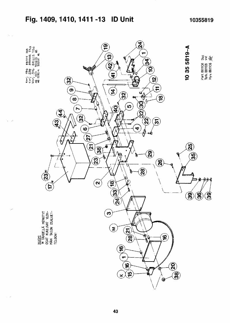
Fig. 1409,1410,1411-13 ID Unit 10355819
«»o- ( rSS
Ccc r r0 O ^ UJ
0)T-00in
COo
43
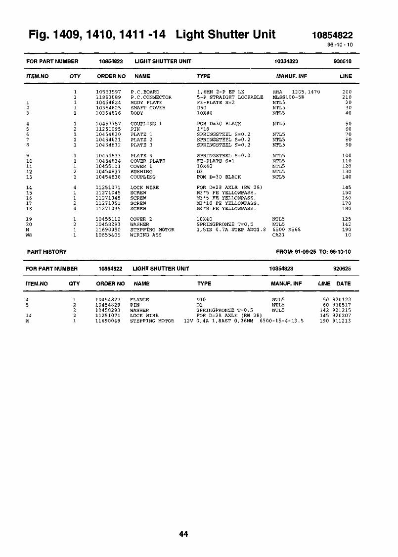
Fig. 1409,1410,1411 -14 Light Shutter Unit 1085482296-10- 10
FOR PART NUMBER
ITEM.NO
123
45678
910111213
1415161718
1920MW8
QTY
11111
12111
11121
41124
1211
PART HISTORY
FOR PART NUMBER
ITEM.NO QTY
10854822
ORDER NO
1055359711863089104548241035482510354826
1045775711251095104548301045483110454832
1045483310454834104551111045483710454838
1125107111271045112710451127105111271035
10455112104582931169005010855405
10854822
ORDER NO
LIGHT SHUTTER UNIT
NAME
P.C.BOARDP.C.CONNECTORBODY PLATESHAFT COVERBODY
COUPLING 1PINPLATE 1PLATE 2PLATE 3
PLATE 4COVER PLATECOVER 1BUSHINGCOUPLING
LOCK WIRESCREWSCREWSCREWSCREW
COVER 2WASHERSTEPPING MOTORWIRING ASS
LIGHT SHUTTER UNIT
NAME
TYPE
1,6MM 2-P EP LK5-P STRAIGHT LOCKABLEFE-PLATE S=2D5010X40
POM D=30 BLACK1*18SPRINGSTEEL S=0.2SPRINGSTEEL S=0.2SPRINGSTEEL S=0.2
SPRINGSTEEL S=0.2FE-PLATE S=l10X40D3POM D=3 0 BLACK
FOR D=28 AXLE (RW 28)M3*5 FE YELLOWPASS.M3*5 FE YELLOWPASS.M3*16 FE YELLOWPASS.M4*8 FE YELLOWPASS.
10X40SPRINGPRONZE T=0,51,5IN 0.7A STEP ANG1.8
TYPE
10354823
MANUF. INF
930518
LINE
RRA 1205,1470 200MLSS100-5BNTL5NTL5NTL5
NTL5
NTL5NTL5NTL5
NTL5NTL5NTL5NTL5NTL5
NTL5NTL56500 R568CA21
FROM: 91-09-25
10354823
MANUF. INF
210203040
5060708090
100110120130140
145150160170180
12514219010
TO: 96-10-10
920625
LINE DATE
45
14M
12221
1045482710454829104582931125107111690049
FLANGEPINWASHERLOCK WIRESTEPPING MOTOR
D3 0DlSPRINGPRONZE T=0,5FOR D=2 8 AXLE (RW
12V 0,4A 1.8AST 0.26NM
NTL5NTL5NTL5
28)6500-15-4-13.5
5060
142145190
920122930517921215920207911213
44
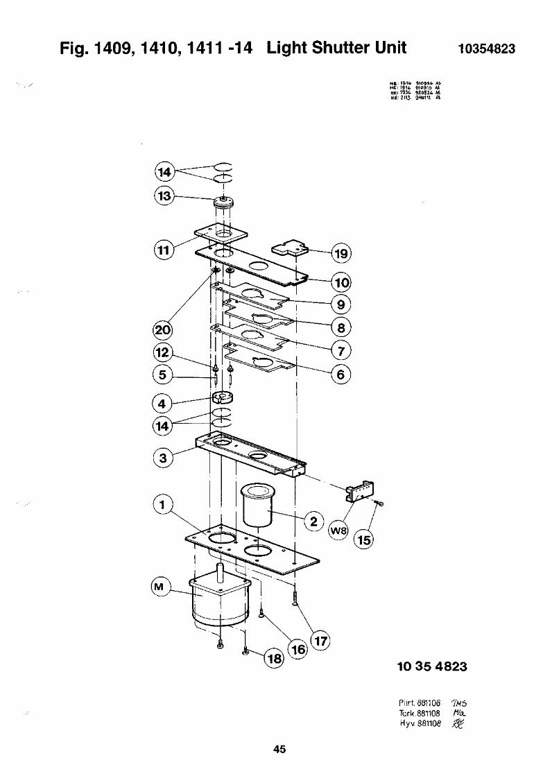
Fig. 1409,1410,1411 -14 Light Shutter Unit 10354823
ME: 1B1<> SkO&Lb ASME' 191fc 910910 ASHE; 1931. 92052.C A4HE. 2113 910111 *1
10 35 4823
45
Pi irt. 561108 TW5Tark.881108 fVa.Hyv. 881108 &

Fig.1409,1410,1411 -15 Motor Unit 1 108550649 6 - 1 0 - 1 0
FOR PART NUMBER
ITEM.NO
12345
678910
1112131415
1617181920
2122KM1.M2
QTY
11121
22111
13881
11241
1222
PART HISTORY
FOR PART 1
ITEM.NO
MUMBER
QTY
10855064
ORDER NO
1025506610455067103537991035376110357482
1035438810454867113500981045506810455069
1135007311350072112500081127400711275008
1127500711278015105535971132010611350076
11350077112510371186308911690042
10855064
ORDER NO
MOTOR UNIT 1
NAME
MOUNTING BRACKETAXLECOGGED BELT WHEELCOGGED BELT WHEELCOGGED BELT WHEEL
GOGGED BELT WHEELPLATECOG WHEELAXLEBEARING HOUSE
JOURNAL BEARINGJOURNAL BEARINGWASHERSCREWSCREW
SCREWNUTP.C.BOARDLOCK. CARD SPACERCOGGED BELT
COGGED BELTGRIP RINGP.C.CONNECTORSTEPPING MOTOR
MOTOR UNIT 1
NAME
TYPE
FE-PLATE S=2,5D6H8PA6+30% MINERALPA6+3 0% MINERALZ 28
GRILON W 5239FE-PLATE S=2Z10D6H86K14
10355065
MANUF. INF
NTL5NTL512971297NTL5
12971409,1235,1297S6-10NTL5NTL5
GLYCODUR PG 060810 FGLYCODUR PBG 060804 F4 . 3 / 9 * 0 . 8 FE YELLOWPASS.M4*12 FE YELLOWPASS.M4*6 AISI316
M4*4Ml2 FE YELLOWPASS.1,6MM 2-P EP LKNYLONSYNCHROFLEX
RRA 1205KGLS-3S6 T2,5/120
SYNCHROFLEX 10 T 2 , 5 / 1 6 0FOR D6 AXLE G65-P STRAIGHT LOCKABLE MLSS100-5B5V 1A 1.8AST 0,4NM 6 5 0 0 - 2 0 - 4 - 4 . 8
TYPE
FROM: 91-09-25
10355065
MANUF. INF
941026
LINE
1020304050
60708090
100
110120150160170
180190
,1470 220230130
14045
240R416 215
TO: 96-10-10
941026
LINE DATE
M lM2
11690043 STEPPING MOTOR11690042 STEPPING MOTOR
5V 1,5A 1,8AST 0,835NM PH268-215V 1A 1.8AST 0,4NM PH265-04
210 920212215 920211
46
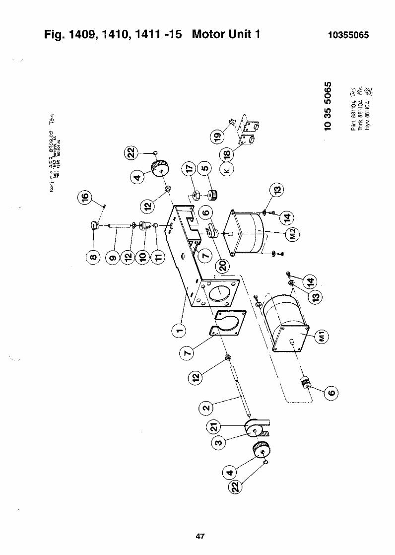
Fig. 1409,1410,1411-15 Motor Unit 1 10355065
Sss
mCOoin8
£2 oCO COCO QD
47
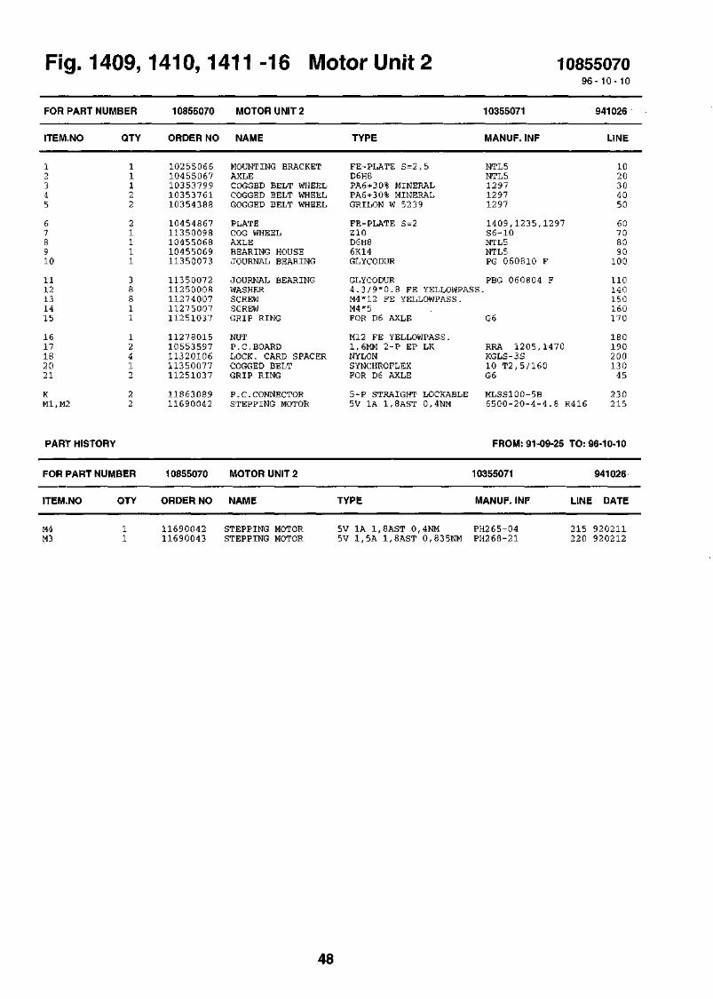
Fig. 1409,1410,1411-16 Motor Unit 2 1085507096-10-10
FOR PART
ITEM.NO
12345
678910
1112131415
1617182021
KM1,M2
NUMBER
QTY
11122
21111
38811
12412
22
PART HISTORY
FOR PART
ITEM.NO
NUMBER
QTY
10855070
ORDER NO
1025506610455067103537991035376110354388
1045486711350098104550681045506911350073
1135007211250008112740071127500711251037
1127801510553597113201061135007711251037
1186308911690042
10855070
ORDER NO
MOTOR UNIT 2
NAME
MOUNTING BRACKETAXLECOGGED BELT WHEELCOGGED BELT WHEELGOGGED BELT WHEEL
PLATECOG WHEELAXLEBEARING HOUSEJOURNAL BEARING
JOURNAL BEARINGWASHERSCREWSCREWGRIP RING
NUTP.C.BOARDLOCK. CARD SPACERCOGGED BELTGRIP RING
P.C.CONNECTORSTEPPING MOTOR
MOTOR UNIT 2
NAME
TYPE
FE-PLATE S=2,5D6H8PA6+3 0% MINERALPA6+3 0% MINERALGRILON W 523 9
FE-PLATE S=2Z10D6H86K14GLYCODUR
10355071
MANUF. INF
NTL5NTL5129712971297
1409 ,1235 ,1297S6-10NTL5NTL5PG 060810 F
GLYCODUR PBG 060804 F4 . 3 / 9 * 0 . 8 FE YELLOWPASS.M4*12 FE YELLOWPASS.M4*5FOR D6 AXLE G6
Ml2 FE YELLOWPASS.1,6MM 2-P EP LKNYLONSYNCHROFLEXFOR D6 AXLE
RRA 1205,1470KGLS-3S10 T2,5/160G6
5-P STRAIGHT LOCKABLE MLSS100-5B5V 1A 1,8AST 0,4NM 6 5 0 0 - 2 0 - 4 - 4 . 8
TYPE
FROM: 91-09-25
10355071
MANUF. INF
941026
LINE
1020304050
60708090
100
110140150160170
180190200130
45
230R416 215
TO: 96-10-10
941026
LINE DATE
M4M3
11690042 STEPPING MOTOR11690043 STEPPING MOTOR
5V 1A 1,8AST 0,4NM PH265-045V 1,5A 1,8AST 0,835NM PH268-21
215 920211220 920212
48

Fig. 1409,1410,1411 -16 Motor Unit 2 10355071
oo CO
o
oo
£
49

Fig. 1409,1410,1411 -17 Count Weight 1085478996-10-10
FOR PART NUMBER 10854789 COUNT WEIGHT 10454790 960620
ITEM.NO QTY ORDER NO NAME TYPE MANUF. INF LINE
1 10454794 BUSHING1 10454795 TUBE1 10454796 BUSHING3 11350073 JOURNAL BEARING3 11350075 JOURNAL BEARING
1 11251070 LOCK WIRE1 11251069 LOCK WIRE1 10454793 AXLE1 11251055 PIN
MS-ROD D30D10H8MS-ROD D3 6GLYCODURGLYCODUR
FOR D=10 AXLE (RW 10)FOR D=6 AXLE (RW 6)D6H82*10 RUSTPROOF
NTL5NTL5NTL5PG 060810 FPG 101210 F
NTL5
1520304050
60701080
PART HISTORY FROM: 91-09-25 TO: 96-10-10
FOR PART NUMBER 10854789 COUNT WEIGHT 10454790 960620
ITEM.NO QTY ORDER NO NAME TYPE MANUF. INF LINE DATE
11113
3111
1045479310454794104547951045479611350073
11350075112510701125106911251055
AXLEBUSHINGTUBEBUSHINGJOURNAL BEARING
JOURNAL BEARINGLOCK WIRELOCK WIREPIN
D6H8MS-ROD D3 0D10H8MS-ROD D3 6GLYCODUR
GLYCODURFOR D=10 AXLE (RW 10)FOR D=6 AXLE (RW 6)2*10 RUSTPROOF
NTL5NTL5NTL5NTL5PG 060810 F
PG 101210 F
1015203040
50607080
931115931115931115931115931115
931115931115931115931115
50
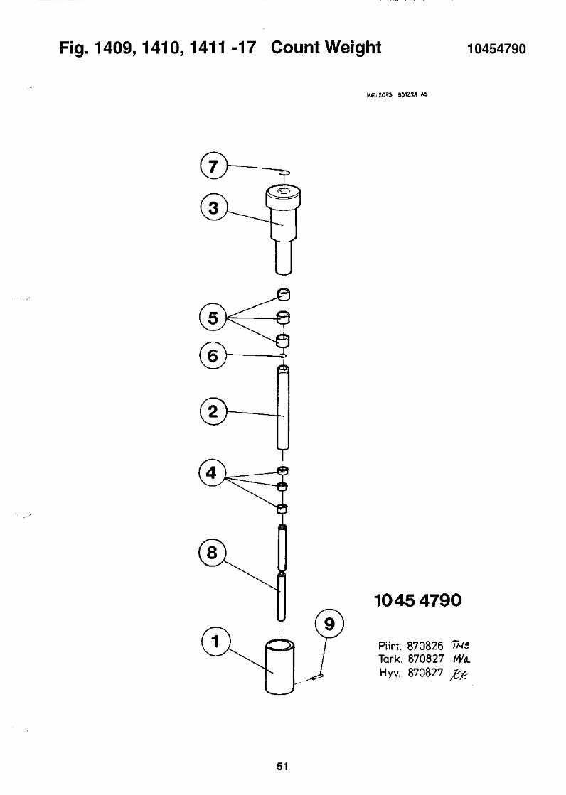
Fig. 1409,1410,1411 -17 Count Weight 10454790
ME. 1013 9J1Z11
1045 4790
Piirt. 870826 TN5Tark. 870827Hyv. 870827
51
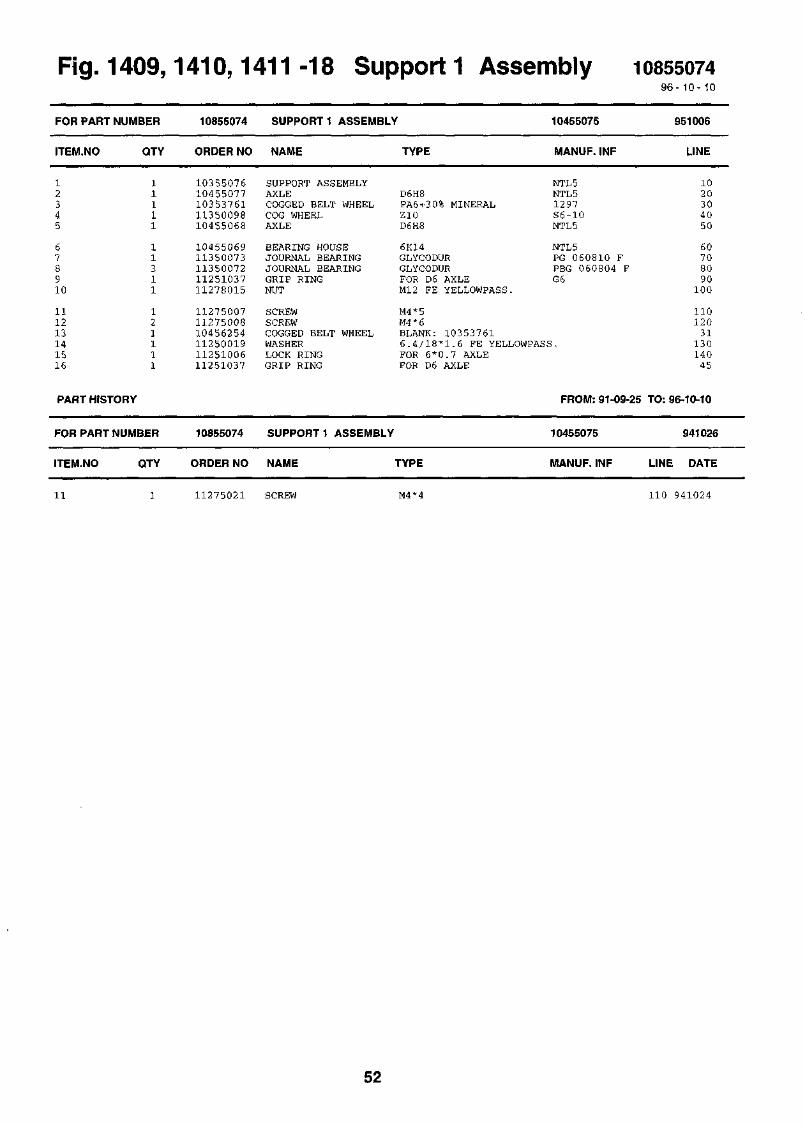
Fig. 1409,1410,1411 -18 Support 1 Assembly 108550749 6 - 1 0 - 1 0
FOR PART NUMBER
ITEM.NO
12345
678910
111213141516
QTY
11111
11311
121111
PART HISTORY
FOR PART NUMBER
ITEM.NO QTY
10855074
ORDER NO
1035507610455077103537611135009810455068
1045506911350073113500721125103711278015
112750071127500810456254112500191125100611251037
10855074
ORDER NO
SUPPORT 1 ASSEMBLY
NAME
SUPPORT ASSEMBLYAXLECOGGED BELT WHEELCOG WHEELAXLE
BEARING HOUSEJOURNAL BEARINGJOURNAL BEARINGGRIP RINGNUT
SCREWSCREWCOGGED BELT WHEELWASHERLOCK RINGGRIP RING
TYPE
D6H8PA6+3 0% MINERALZ10D6H8
6K14GLYCODURGLYCODURFOR D6 AXLEMl2 FE YELLOWPASS.
10455075
MANUF. INF
NTL5NTL51297S6-10NTL5
NTL5PG 060810 FPBG 060804 FG6
M4*5M4*6BLANK: 1 0 3 5 3 7 6 16 . 4 / 1 8 * 1 . 6 FE YELLOWPASS.FOR 6 * 0 . 7 AXLEFOR D6 AXLE
SUPPORT 1 ASSEMBLY
NAME TYPE
FROM: 91-09-25
10455075
MANUF. INF
951006
LINE
1020304050
60708090
100
110120
31130140
45
TO: 96-10-10
941026
LINE DATE
11 11275021 SCREW M4*4 110 941024
52

Fig. 1409,1410,1411 -18 Support 1 Assembly 10455075
io
o
o
£2 en £2o o o00 co co00 co 00
53

Fig. 1410, -19 Support 2 Assembly 108550789 6 - 1 0 - 10
FOR
ITEM
12345
678910
111213141516
PART NUMBER
I.NO QTY
11111
11131
121111
PART HISTORY
FOR
ITEM
PART NUMBER
.NO QTY
10855078
ORDER NO
1035507610455077103537611035748211350098
1045506810455069113500731135007211278015
112750071127500810456254112500191125100611251037
10855078
ORDER NO
SUPPORT 2 ASSEMBLY
NAME
SUPPORT ASSEMBLYAXLECOGGED BELT WHEELCOGGED BELT WHEELCOG WHEEL
AXLEBEARING HOUSEJOURNAL BEARINGJOURNAL BEARINGNUT
SCREWSCREWCOGGED BELT WHEELWASHERLOCK RINGGRIP RING
TYPE
D6H8PA6 + 30% MINERALZ2 8Z10
D6H86K14GLYCODURGLYCODURM12 FE YELLOWPASS.
10455079
MANUF. INF
NTL5NTL51297NTL5S6-10
NTL5NTL5PG 060810 FPBG 060804 F
M4*5M4*6BLANK: 1 0 3 5 3 7 6 16 . 4 / 1 8 * 1 . 6 FE YELLOWPASS.FOR 6 * 0 . 7 AXLEFOR D6 AXLE G6
SUPPORT 2 ASSEMBLY
NAME TYPE
FROM: 91-09-25
10455079
MANUF. INF
951006
LINE
1020304050
60708090
100
110120
31130140
45
TO: 96-10-10
951006
LINE DATE
11 11275021 SCREW M4*4 110 941024
54

Fig. 1409,1410,1411 -19 Support 2 Assembly 10455079
0>
oin
in
o
00 00 gof < c~v C*-o 0000 00 OO00 00 00
55

Fig. 1409,1410,1411 -20 Plate Assembly, R 1085505196 -10 - 10
FOR PART NUMBER 10855051 PLATE ASSEMBLY, R 10455052 940929
ITEM.NO QTY ORDER NO NAME TYPE MANUF. INF LINE
2 10855235 P.C.ASSEMBLY1 10355053 GUIDE PLATE RIGHT2 10455054 COVER PLATE3 10455055 PLATE3 11250002 WASHER
4 11274002 SCREW3 11274006 SCREW
SENSOR BOARDAL-PLATE S=2FE-PLATE S=2FE-PLATE S=l,5A4,3 YELLOWPASS.
M3*6 FE YELLOWPASS.M4*10 FE YELLOWPASS.
RSV 10455234NTL5NTL5NTL5
1020304050
6070
56

Fig. 1409,1410,1411 -20 Plate Assembly, R 10455052
" ' in u)CD 0) CDO CO ^-^
ooco°°OO 00 OO
57

Fig. 1410,1411 -21 Plate Assembly,
1085523510355058104550541045505511250002
P.C.ASSEMBLYGUIDE PLATE LEFTCOVER PLATEPLATEWASHER
1085505696-10-10
FOR PART
ITEM.NO
NUMBER
QTY
10855056
ORDER NO
PLATE ASSEMBLY, L
NAME TYPE
10455057
MANUF. INF
940929
LINE
11274002 SCREW11274006 SCREW10455888 HOLDER
SENSOR BOARDAL-PLATE S=2FE-PLATE S=2FE-PLATE S=l,5A4 , 3 YELLOWPASS.
M3*6 FE YELLOWPASS.M4*10 FE YELLOWPASS.FE-PLATE S=2
RSV 10455234NTL5NTL5NTL5
NTL5
102 03 04050
607031
58
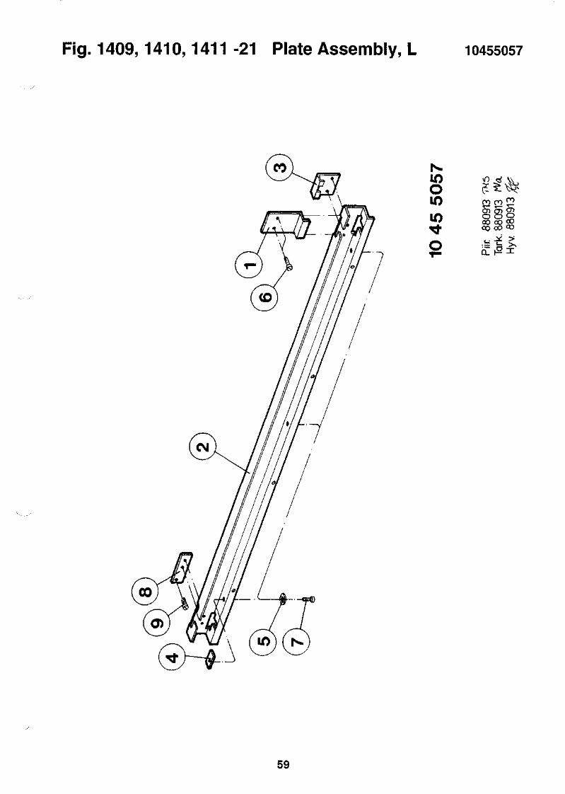
Fig. 1409,1410,1411 -21 Plate Assembly, L 10455057
Om
o o o° 0 OO CO
oo oo °o
a.
59
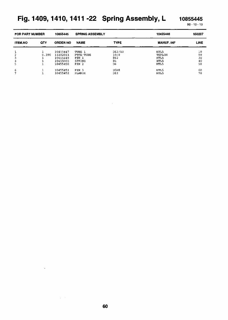
Fig. 1409,1410,1411 -22 Spring Assembly, L 108554459 6 - 1 0 - 10
FOR PART
ITEM.NO
NUMBER
QTY
10855445
ORDER NO
SPRING ASSEMBLY
NAME TYPE
10455446
MANUF. INF
950207
LINE
1 10455447 TUBE 10.390 11182011 PTFE-TUBE1 10455449 PIN 11 10455003 SPRING1 10455450 PIN 2
1 104554511 10455452
PIN 3FLANGE
D12/1010/8D12DlD8
D5H8D12
NTL5TEFLONNTL5NTL5NTL5
NTL5NTL5
1080304050
6070
60

Fig. 1409,1410,1411 -22 Spring Assembly, L 10455446
61

62

Fig. 1409,1410,1411 -23 HV-Divider Unit 108540239 6 - 1 0 - 10
FOR PART
ITEM.NO
NUMBER
QTY
10854023
ORDER NO
HV-DIVIDER UNIT
NAME TYPE
10355373, 10355106
MANUF. INF
920515
LINE
34567
89101 112
C lC 2 , 3R lR2R 8 , 1 5
0 . 1 0 00 . 4 0 01
11860001114600011125002111250001
1.100 11240035
1124000811240101105540241035537210454836
1126003510454401105445761131000611320106
1127101811271019112710231127800210556568
1162600211626008116011491160404911604209
R17-21,24-28 10 11604241R22,29 2 11604225Sl-4 0.560 11863070
COAXIAL CONNECTORSOLDERING TAGSERRAT LOCK WASHERWASHERCOAXIAL CABLE
HV WIRECOPPER WIREP.C.BOARDPLATENUT
RISE PINBOXLABELCLAMPLOCK. CARD SPACER
SCREWSCREWSCREWNUTLABEL
CAPACITOR H.V.CAPACITOR H.V.RESISTORRESISTOR MF SMRESISTOR MF SM
RESISTOR MF SMRESISTOR MF SMP.C.CONNECTOR
D 5.5/3.5*83.0 ANNEALED YELLOWPASA3,2 YELLOWPASS.
1000V PVCD 0,81,6MM 2-P EP LKFE-PLATE S=l6K6
M3*10ABS-PLATE S=2WARNING LABELMS 1.25 MKLNYLON
M3*6 FE YELLOWPASS.M3*8 FE YELLOWPASS.M3*14 FE YELLOWPASS.M3 FE YELLOWPASS.WHITE-SELF-ADHESIVE-L
2.5NF 3 KV150PF 3.0KV 20/50%10K 2% 0.5W100 1% 0,125W 100PPM215K 1% 0,125W 100PPM
l,00M 1% 0,125W 100PPM464K 1% 0,125W 100PPM40-PIN STRAIGHT
11H4-50-3 -1A2 021 ME3 . 2 * 5 . 5 * 0 . 4 5
RG-58 C/U BLACK
RRH 1410NTL5NTL5
5 . 0 3 . 1 0 31205DANGER H.V. SERIVAA 3024 ASAKGLS-3S
HV-OUTPUT-INPUT
DD30 2529 / 0 1 3 0 . 9 D FERROPB 1/2 BEYSCHLAG
SL1/25/36G
8090
1401 3 5100
105110
70150160
1701 8 01902 0 02 1 0
2 2 02 3 02 4 01301 8 1
1020304050
454360
63

Fig. 1409,1410, -23 HV-Divider Unit 1085936996-10-10
FOR PART NUMBER 10859369 HV-DIVIDER UNIT RFA 10359368, 10355373 960607
ITEM.NO QTY ORDER NO NAME TYPE
D 5.5/3.5*83.0 ANNEALED ZINKEDA3, 2
1,6MM 2-P EP LKFE- PLATE S=lMS 6K6M3*10 MSABS S=2
MS 1.25 MKLNYLONM 3*6 FE YELLOWPASS.M 3*8 FE YELLOWPASS.
M 3*14 FE YELLOWPASS.M3 FE YELLOWPASS.WHITE-SELF-ADHESIVE-LD 6, 6 MMM2.5*4 FE BLACK
PRESPAN S=0,52.5NF 3KV150PF 3.0KV 20/50%10K 2% 0.5W100 1% 0,125W 100PPM
1.00M 1% 0,125W 100PPM
464K 1% 0,125W 100PPM22Mohm 5% 0.5W 3.5kVDC215K 1% 0,125W 100PPM40-PIN STRAIGHT
MANUF. INF
11H4-50-3-1A2 021 ME3.2*5.5*0.45
RG-58 C/U
RRH 14101415NTL55.03.1031205
DANGER H.V. SERIVAA 3024 ASAKGLS-3S
HV-OUTPUT-INPUT28B2025-OAO
DD30 2529/0130.9 D FERROPB 1/2 BEYSCHLAGCRCW1206
CRCW1206
CRCW1206232224213226CRCW1206SL1/25/36G
LINE
30110190200210
230260240180250
270130120170160
150140220115135
280504010090
60
70958020
1234
56789
1011121314
15ClC2-5RlR2
R3-7 ,10-14 ,1 7 - 2 1 , 2 4 - 2 8 .R8 ,15 ,22 ,29R9,16 ,23 ,30R31-34S l -8
11541.090
11321
11236
38124
11411
20
4441.111
11860001 COAXIAL CONNECTOR11460001 SOLDERING TAG11250021 SERRAT LOCK WASHER11250001 WASHER11240035 COAXIAL CABLE
10554024 P.C.BOARD10358910 PLATE10454836 NUT11260035 RISE PIN10454401 BOX
10544576 LABEL11310006 CLAMP11320106 LOCK. CARD SPACER11271018 SCREW11271019 SCREW
11271023 SCREW11278002 NUT10556568 LABEL11480047 FERRITE CLAMP11273013 SCREW
10461951 INSULATOR PLATE11626002 CAPACITOR H.V.11626008 CAPACITOR H.V.11601149 RESISTOR11604049 RESISTOR MF SM
11604241 RESISTOR MF SM
11604225116038681160420911863070
RESISTOR MF SMHV RESISTORRESISTOR MF SMP.C.CONNECTOR
64

j 8<?O(b6SHE 2158 940W} ASME: 1132.-A J5112.O ASME: 2^14-5 91,01.10 AS
CD
OCO
en
o
•N>CO
q<"E
10 35 5373-B
Piirt. 881107Tark. 881107Hyv. 881107
OCOO l
enCO-siCO

66
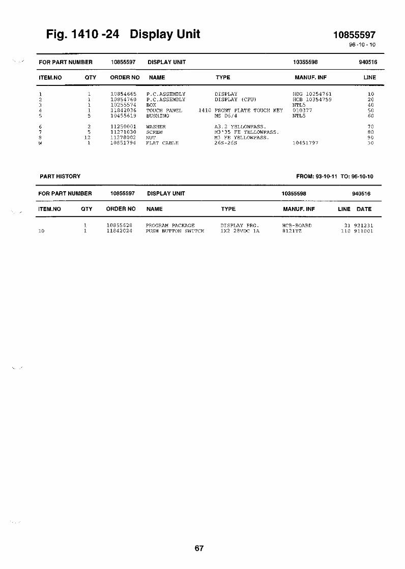
Fig. 1410-24 Display Unit 1085559796-10-10
FOR PART
ITEM.NO
NUMBER
QTY
10855597
ORDER NO
DISPLAY UNIT
NAME TYPE
10355598
MANUF. INF
940516
LINE
11115
25
121
1085466510854760102555741184203610455619
11250001112710301127800210851794
P.C-ASSEMBLYP.C.ASSEMBLYBOXTOUCH PANELBUSHING
WASHERSCREWNUTFLAT CABLE
DISPLAYDISPLAY (CPU)
1410 FRONT PLATE TOUCH KEYMS D6/4
A3,2 YELLOWPASS.M3*3 5 FE YELLOWPASS.M3 FE YELLOWPASS.26S-26S
HDG 10254761HCB 10354759NTL5010377NTL5
10451797
1020405060
70809030
PART HISTORY FROM: 93-10-11 TO: 96-10-10
FOR
ITEM
10
PART
.NO
NUMBER
QTY
11
10855597
ORDER NO
1085562811842024
DISPLAY UNIT
NAME
PROGRAM PACKAGEPUSH BUTTON SWITCH
TYPE
DISPLAY PRG.1X2 2 8VDC 1A
10355598
MANUF. INF
HCB-BOARD8121YZ
LINE
21110
940516
DATE
921231911001
67

Fig. 1409,1411 -24 Display Unit 108592879 6 - 10-10
FOR PART
ITEM.NO
NUMBER
QTY
10859287
ORDER NO
DISPLAY UNIT
NAME
1400-SERIES
TYPE
10355598
MANUF. INF
960612
LINE
12346
89121314
1516171819
202 1222324
25262728
W25W2 6W33
PART HISTORY
11112
41221
11296
28121
10.05010 .850
111
1085466510854760102592831184203611250001
1127800210557386114800491148005011240162
1036169110361690104616891127601511271021
1127102611250044112710181125000610861635
10861638111800171045369711220014
108517941085559210861704
P.C.ASSEMBLYP.C.ASSEMBLYBOXTOUCH PANELWASHER
NUTLABELFERRITE CLAMPCLAMPRF GASKET
LID ASSEMBLYBOX ASSEMBLYBUSHINGSCREWSCREW
SCREWWASHERSCREWWASHERP.C.ASSEMBLY
P.C.ASSEMBLYPE-STRINGINSULATOR PLATETAPE
FLAT CABLEFLAT CABLEFLAT CABLE
DISPLAYDISPLAY (CPU)ASSEMBLY
A 3 , 2
M3 FE YELLOWPASS.PVC FASKAL-400 T = 0 , l26-WIRE FLAT CABLEFOR 26-W.FLAT C. CLAPM3 , 2 X 4 , 8 MONEL
TIN COVEREDTIN COVEREDMSC 2 . 9 * 6 . 5 FE YELLOWPASSM 3 * 1 0 FE YELLOWPASS.
M 3*18 FE YELLOWPASS.3 . 2 / 9 * 0 . 8 FE YELLOWPASSM 3*6 FE YELLOWPASS.3 . 2 / 7 * 0 . 5 FE YELLOWPASSFILTER BOARD
FILTER BOARD5 * 5 , BLACKPRESPAN S = 0 , 512MM CLEAR
26S-26S50S-50S34S-34S
HDG 10254761HCB 103547591415010377
1410 RESET28B2022-000M-CLIP01-0901-6601
NTL-5NTL-5NTL-5
RYP 10461634
RYQ 10461637PZ-940 SJH1205TESA4971
10451797FC35 10455666FC220 10461703
5 1 05205405505 7 0
5 9 06 0 06106206 3 0
6406506606706 8 0
6907 0 07 1 07 2 05 2 5
5 3 57 3 07 4 07 5 0
530533537
FROM: 93-11-11 TO: 96-10-10
FOR PART
ITEM.NO
NUMBER
QTY
10859287
ORDER NO
DISPLAY UNIT
NAME
1400-SERIES
TYPE
10355598
MANUF. INF
960612
LINE DATE
7W57
11
15154
112
1085562811271030108517941045561911271030
1127102911278002
PROGRAM PACKAGESCREWFLAT CABLEBUSHINGSCREW
SCREWNUT
DISPLAY PRG. HCB-BOARDM3*35 FE YELLOWPASS26S-26S 10451797MS D6/4 NTL5M 3*35 FE YELLOWPASS.
M 3*30 FE YELLOWPASS.M3 FE YELLOWPASS.
521 930825580 940405530 960213560 960115580 960115
585 960115590 960112
68

Fig.1409,1410,1411 -24 Display Unit 10355598
69

Fig. 1410, Thermostat Unit 108563219 6 - 1 0 - 10
FOR PART NUMBER 10856321 THERMOSTAT UNIT 10156322 930909
ITEM.NO QTY ORDER NO NAME TYPE MANUF. INF LINE
12345
678910
1112131415
1617181920
2122232425
2627282930
3132333435
36373839W29
20.0800.65010.150
11112
24444
41222
21422
22111
263342
1428410
142211
1131002611183019111830271131003811141024
1085634210256323102563241035632510456326
1035632710456328104563291045633010456331
1045633210256333104563341045633510456336
1045633710356338104519611169100011802009
1173100711450027116900451169004011690046
1125000811250021112710191127105311271057
1127400611274072112740091127414211276015
1127800311814502116050341131003110856411
WIRE TIEPVC-INSULAITINGPVC-INSULAITINGCLAMPSILICONE TUBING
P.C.ASSEMBLYCOOLING PROFILINSULATION BOXINSULATIONFASTENING PIECE
COOLING PLATE 1COOLING PLATE 2COOLING PLATE 3COOLING PLATE 4COOLING PLATE 5
INSULATION BUSHINGCOVERBUSHINGINSULATION PLATESCREW
BRACKETBOX ASSEMBLYBUSHINGCOLD ELEMENTTRANSISTOR FET
INSULATORINSULATING BUSHFANFINGER GUARDFAN
WASHERSERRAT LOCK WASHERSCREWSCREWSCREW
SCREWSCREWSCREWSCREWSCREW
NUTPTC-SENSORRESISTOR WWCLAMPWIRING ASS
2.4*140 NYLON 66D1.5 BLACKD4,0 BLACK
2.5-0.4
COOLING UNITALUM.PROFIL 95,5*120
PE-PLATE PZ940CU 10X100
CU-PLATE S=lCU-PLATE S=lCU-PLATE S=lCU-PLATE S=lCU-PLATE S=l
POM D10FE-PLATE S=lPOMPOM
FE-PLATE
6/412V50V 12A 75W N-CH MOS
TO-220 MICATO-220,TO-3 CONNECTION24VDC 5W 2800RPM105X105MM24VDC 2,2W 3300RPM
4.3/9*0.8 FE YELLOWPASS3.0 ANNEALED YELLOWPASSM3*8 FE YELLOWPASS.M4*8 FE YELLOWPASS.M4*16 FE YELLOWPASS.
M4*10 FE YELLOWPASS.M4*16 FE YELLOWPASS.M4*20 FE YELLOWPASS.
ACC3 8-A
RRM 10456341NTL5NTL5NTL5NTL5
NTL5NTL5NTL5NTL5NTL5
NTL5NTL5NTL5NTL5NTL5
NTL5NTL51219CP1.4-127-06LBUZ 10
MI61083-37-1143149.601-438314
. 3.2*5.5*0.45
M4*40 AISI 316 ACID-PROOFB2.9*6.5 FE YELLOWPASS.
M4 FE YELLOWPASS.1000R/25AST.C 2%10R 5% 50W
KTY81-120HSA50A3031ASACA50
370390400410420
1020304050
60708090
100
110120130140150
160170180190200
210220230240250
260270280290300
310320330340350
36019119238006
70
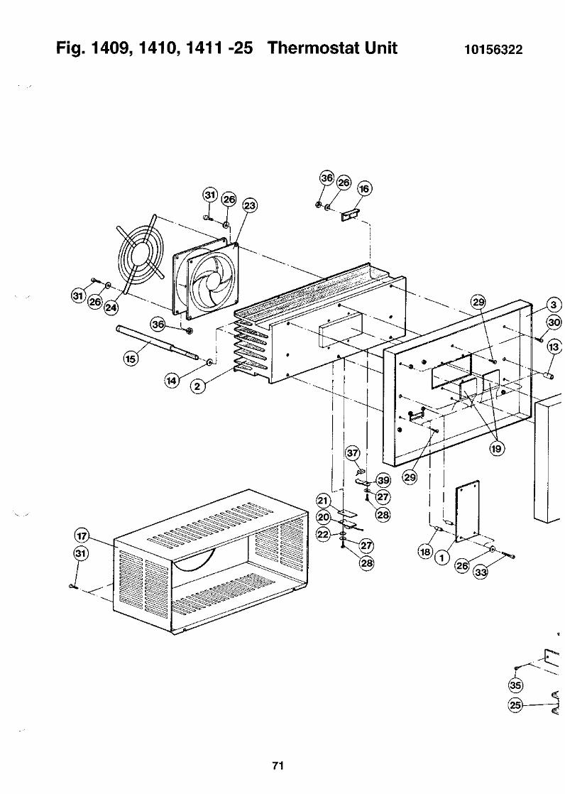
Fig. 1409,1410,1411 -25 Thermostat Unit 10156322
(35
71

72
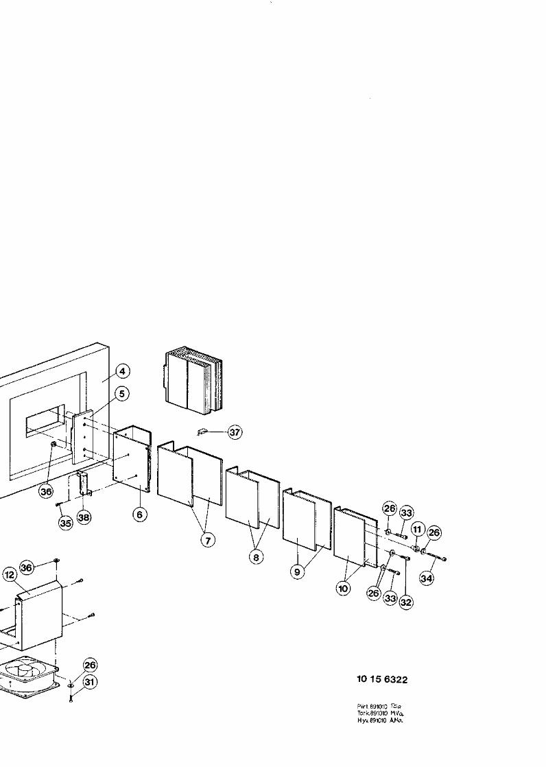
10 15 6322
Piirt. 891010Tark.891010Hyv 891010


1415 Supplement
73

74

1415 LSC 1415-00196-10- 10
FOR PART
fTEM.NO
NUMBER
QTY
1415-001
ORDER NO
LSC
NAME
1415-001
TYPE MANUF. INF
951004
LINE
1 10858924 LSC1 1410-405 SAMPLE TRAY1 1409-411 ID KIT0.500 1200-437 OPTIPHASE" HISAFE\31 1224-313 MULTICALC EDITOR
1 1224-512 PC-PROGRAM1 10859610 PACKAGE
1415-001FOR SAMPLE RACKS1409-4112X5 L
1400 DSA WIW1415
101556001410-405
1200-4371224-313
1224-51210459611
1020304050
60100
Fig. 1415 - 26 LSC Assembly 1085892496 -10 -10
FOR PART NUMBER 10858924 LSC 1415-001 10155600 960314
ITEM.NO QTY ORDER NO NAME TYPE MANUF. INF LINE
910111213
1415161718
1920212223
108552721086109110857653108567301215-111
1044654510551111105604901055550910556126
1056134810561614113100401131003710561102
EXTERNAL STANDARDSTD. CAPSULEP.C.ASSEMBLYDCD EXPANSION KITUNQ.STANDARDS SET
FOOTLABELLABEL SETLABEL SETLABEL
LABELLABELCLAMPCLAMPLABEL
11111
11111
11150 .300
0.300 108560771 108576181 108578100.700 108560781 1411-932
11111
11111
11211
11122
12122
INSTALL.KIT 115VPROGRAM PACKAGEPROGRAM PACKAGEINSTALL.KIT 2 50VINSTRUMENT MANUAL
SW KEY MODULE BOARD
20ML VIALS 3H/14C/BACK
PAG, BLACK, 30% GLASCSA-APPROVED (ALO,08)
VME RACK
PATENTS, BRADY -LABEL11570078 (BRADY)
WARNING STICK, BRADY
FOR 1410MAIN PR. 1409/11 LSCCOMM.PROTOCOLS 1409/11FOR 1.410FOR 1409,1411
10255273 1510361101 1400-SERIES 20RJG 10457652 90DCD 10356465 1001215-111 120
1215,1470(LR52500) BRADYCA22 12-DYNFC33,FC2071410
STD B/PLATECE -LABELACC62-AFCC-A-C8EU-152 10561102.LAB
WALLAC 1400 DSA1409/11/15
1411-932
1099004511560029108549161085581810855338
1085927810859369108617121085646610854884
1085460610853316108540211085928710361369
1036077410360773104555231045532810458890
1045533010455329103588841035888510358886
QC CERTIFICATEMOUSE MATBODY ASSEMBLYID-UNITSAMPLE CHANGER
MEASURING UNITP.C.ASSEMBLYTOP COVER ASSEMBLYP.C.ASSEMBLYP.C.ASSEMBLY
P.C.ASSEMBLYP.C.ASSEMBLYP.C.ASSEMBLYDISPLAY UNITBOX ASSEMBLY
SIDE BOX RIGHTSIDE BOX LEFTBOTTOM ASSEMBLYCAMGUIDE PLATE
BUSHINGPLATELEADLEADLEAD
194*244141014101410
1415HV-DIVIDER UNIT1415MICRO COMPUTERI/O BOARD
MCAPOWER SUPPLYMOTOR CONTROL BOARD1400-SERIES
FE PLATE S=1.0FE PLATE S=1.0
D25FE-PLATE S=3
D12FE-PLATE S=3CAST LEADCAST LEADCAST LEAD
10990045
101549171035585910255339
10354850RFA10359368, 110255462DCD 10356465DIC 10354883
DIE 10354603DPA 10353503HPS 10354022103555981414
14141414NTL5NTL51415
NTL5,1470NTL5141514151415
410414419422424
428429596597605
615620622625650
660670102125
3545556575
8595
105125135
145155165185215
205195225235245
75
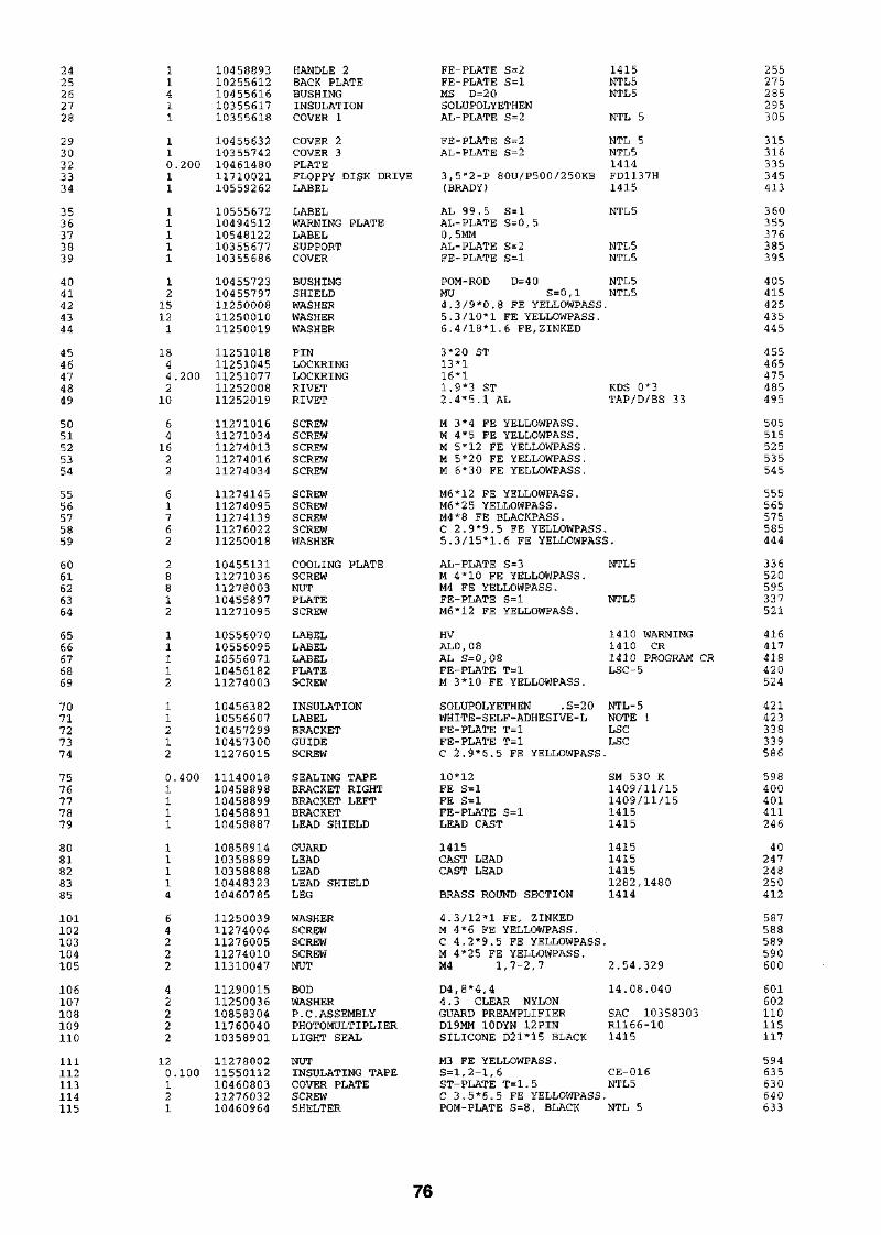
2425262728
2930323334
3536373839
4041424344
4546474849
5051525354
5556575859
6061626364
6566676869
7071727374
7576777879
8081828385
101102103104105
106107108109110
111112113114115
11411
110.20011
11111
12
15121
1844.2002
10
641622
61762
28812
11112
11212
0.4001111
11114
64222
42222
120.100121
1045889310255612104556161035561710355618
1045563210355742104614801171002110559262
1055567210494512105481221035567710355686
1045572310455797112500081125001011250019
1125101811251045112510771125200811252019
1127101611271034112740131127401611274034
1127414511274095112741391127602211250018
1045513111271036112780031045589711271095
1055607010556095105560711045618211274003
1045638210556607104572991045730011276015
1114001810458898104588991045889110458887
1085891410358889103588881044832310460785
1125003911274004112760051127401011310047
1129001511250036108583041176004010358901
1127800211550112104608031127603210460964
HANDLE 2BACK PLATEBUSHINGINSULATIONCOVER 1
COVER 2COVER 3PLATEFLOPPY DISK DRIVELABEL
LABELWARNING PLATELABELSUPPORTCOVER
BUSHINGSHIELDWASHERWASHERWASHER
PINLOCKRINGLOCKRINGRIVETRIVET
SCREWSCREWSCREWSCREWSCREW
SCREWSCREWSCREWSCREWWASHER
COOLING PLATESCREWNUTPLATESCREW
LABELLABELLABELPLATESCREW
INSULATIONLABELBRACKETGUIDESCREW
SEALING TAPEBRACKET RIGHTBRACKET LEFTBRACKETLEAD SHIELD
GUARDLEADLEADLEAD SHIELDLEG
WASHERSCREWSCREWSCREWNUT
BODWASHERP.C.ASSEMBLYPHOTOMULTIPLIERLIGHT SEAL
NUTINSULATING TAPECOVER PLATESCREWSHELTER
FE-PLATE S=2FE-PLATE S=lMS D=20SOLUPOLYETHENAL-PLATE S=2
FE-PLATE S=2AL-PLATE S=2
3,5"2-P 80U/P500/250KB(BRADY)
AL 99.5 S=lAL-PLATE S=0,50, 5MMAL-PLATE S=2FE-PLATE S=l
POM-ROD D=40MU S=0,l4.3/9*0.8 FE YELLOWPASS5.3/10*1 FE YELLOWPASS.6.4/18*1.6 FE,ZINKED
3*20 ST13*116*11.9*3 ST2.4*5.1 AL
M 3*4 FE YELLOWPASS.M 4*5 FE YELLOWPASS.M 5*12 FE YELLOWPASS.M 5*20 FE YELLOWPASS.M 6*30 FE YELLOWPASS.
M6*12 FE YELLOWPASS.M6*25 YELLOWPASS.M4*8 FE BLACKPASS.C 2.9*9.5 FE YELLOWPASS
1415NTL5NTL5
NTL 5
NTL 5NTL 51414FD1137H1415
NTL 5
NTL 5NTL5
NTL5NTL5
KDS 0*3TAP/D/BS 33
5.3/15*1.6 FE YELLOWPASS.
AL-PLATE S=3M 4*10 FE YELLOWPASS.M4 FE YELLOWPASS.FE-PLATE S=lM6*12 FE YELLOWPASS.
HVAL0,08AL S=0,08FE-PLATE T=lM 3*10 FE YELLOWPASS.
SOLUPOLYETHEN . S = 2 0WHITE-SELF-ADHESIVE-LFE-PLATE T=lFE-PLATE T=lC 2.9*6.5 FE YELLOWPASS
10*12FE S = lFE S = lFE-PLATE S=lLEAD CAST
1415CAST LEADCAST LEAD
BRASS ROUND SECTION
4.3/12*1 FE, ZINKEDM 4*6 FE YELLOWPASS.C 4.2*9.5 FE YELLOWPASSM 4*2 5 FE YELLOWPASS.M4 1,7-2,7
D4,8*4,44.3 CLEAR NYLONGUARD PREAMPLIFIERD19MM 10DYN 12PINSILICONE D21*15 BLACK
M3 FE YELLOWPASS.S=l,2-1,6ST-PLATE T=1.5C 3.5*6.5 FE YELLOWPASSPOM-PLATE S=8, BLACK
NTL 5
NTL5
1410 WARNING1410 CR1410 PROGRAM CRLSC-5
NTL-5NOTE !LSCLSC
SM 530 K1409/11/151409/11/1514151415
1415141514151282,14801414
2.54.329
14.08.040
SAC 10358303R1166-101415
CE-016NTL5
NTL 5
255275285295305
315316335345413
360355376385395
405415425435445
455465475485495
505515525535545
555565575585444
336520595337521
416417418420524
421423338339586
598400401411246
40247248250412
587588589590600
601602110115117
594635630640633
76

116117118119120
121122123124125
12612710255462-3710255462-2310355819-43
10355819-4410355819-17
W24W2 6W32
20.100121
14212.700
1.8001111
11
11
1127105310361270108614101127415610460762
1046076111274002104612761046141411240173
1124016210461613115700611035860010457903
1035790210355762
108613461085559210861411
SCREWPB -PLATEP.C.ASSEMBLYSCREWPLATE RIGHT
PLATE LEFTSCREWHOLDERSUPPORT 1RF GASKET
RF GASKETHOLDERLABELCOVER PLATEPLATE
SUPPORTID-SHIELD
FLAT CABLEFLAT CABLEWIRING ASS
M4*8 FE YELLOWPASS.PB 99.6%, NICKELIZEDCONNECTION BOARDM6*16 ST YELLOWPASS.FE PLATE S=2.0
FE PLATE S=2.0M 3*6 FE YELLOWPASS.FE-PLATE S=l NICKELIZEDFE PLATE S=1.06,3 5x6,3 5 MONEL, GLUE
3,2X4,8 MONELFE-PLATE T=lWALLAC 52X22,16STICKERPOLYCARBON S=0.375ST-PLATE T=l,5
RST. T=0,8FE-PLATE S=l
40S-40S50S-50S
1400 -SERIERGE 10461408
1414
1414
141401-0901-6603
01-0901-66011409
14151410
1410NTL 5
FC207 10461300FC35 10455666CA210
638252112556680
690700710720730
74072535035222
23645
127128130
PART HISTORY FROM: 91-09-25 TO: 96-10-10
FOR PART NUMBER 10858924 LSC 1415-001 10155600 960314
ITEM.NO QTY ORDER NO NAME TYPE MANUF. INF LINE DATE
87
W24
1415
3285
4243
47505255116
111
0. 50041
108
44
1282
1157006110358600105554081055111110855268
1085927910855508103555641035556710355568
1045557210458900115700781125000811250010
1125107711271016112740131127414511274156
0.300 10556201
LABELCOVER PLATELABEL SETLABELSTD. CAPSULE
TOP COVER ASSEMBLYFLAT CABLEFRONT BOX ASSEMBLYSIDE BOX RIGHTSIDE BOX LEFT
PLATE 2FOOTLABELWASHERWASHER
LOCKRINGSCREWSCREWSCREWSCREWLABEL
WALLAC 52X22,16 STICKERPOLYCARBON S=0.375
AL-PLATE S=0.8
141540S-40S
FE-PLATE S=lFE-PLATE S=l
FE S = lTHERMAL TRANSFER PRINT4.3/9*0.8 FE YELLOWPASS.5.3/10*1 FE YELLOWPASS.
16*1M 3*4 FE YELLOWPASS.M 5*12 FE YELLOWPASS.M6*12 FE YELLOWPASS.M6*16 ST YELLOWPASS.WARNING STICK PVC ALUM
1415CA22LR52500
3503 52419404
10455269 (NTL-5)20
10255462FC3 3NTL 5NTL5NTL 5
NTL 51415THT-5-438-10
EUROPIUM 152
55127135145155
335412414425435
475505525555556605
930315930315940202941214950216
960122951128960116960116960116
960313950612950508960116960116
950324960116960116950324960116950216
77

78
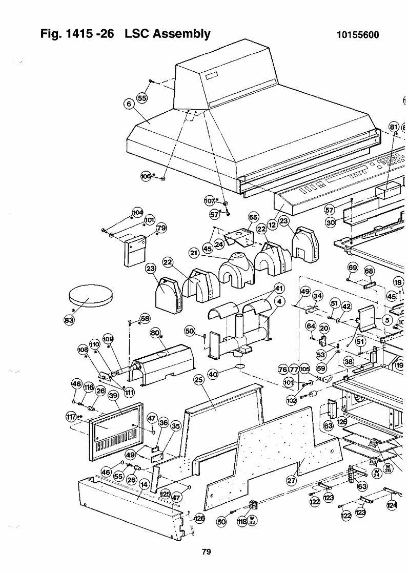
Fig. 1415 -26 LSC Assembly 10155600
' %
79
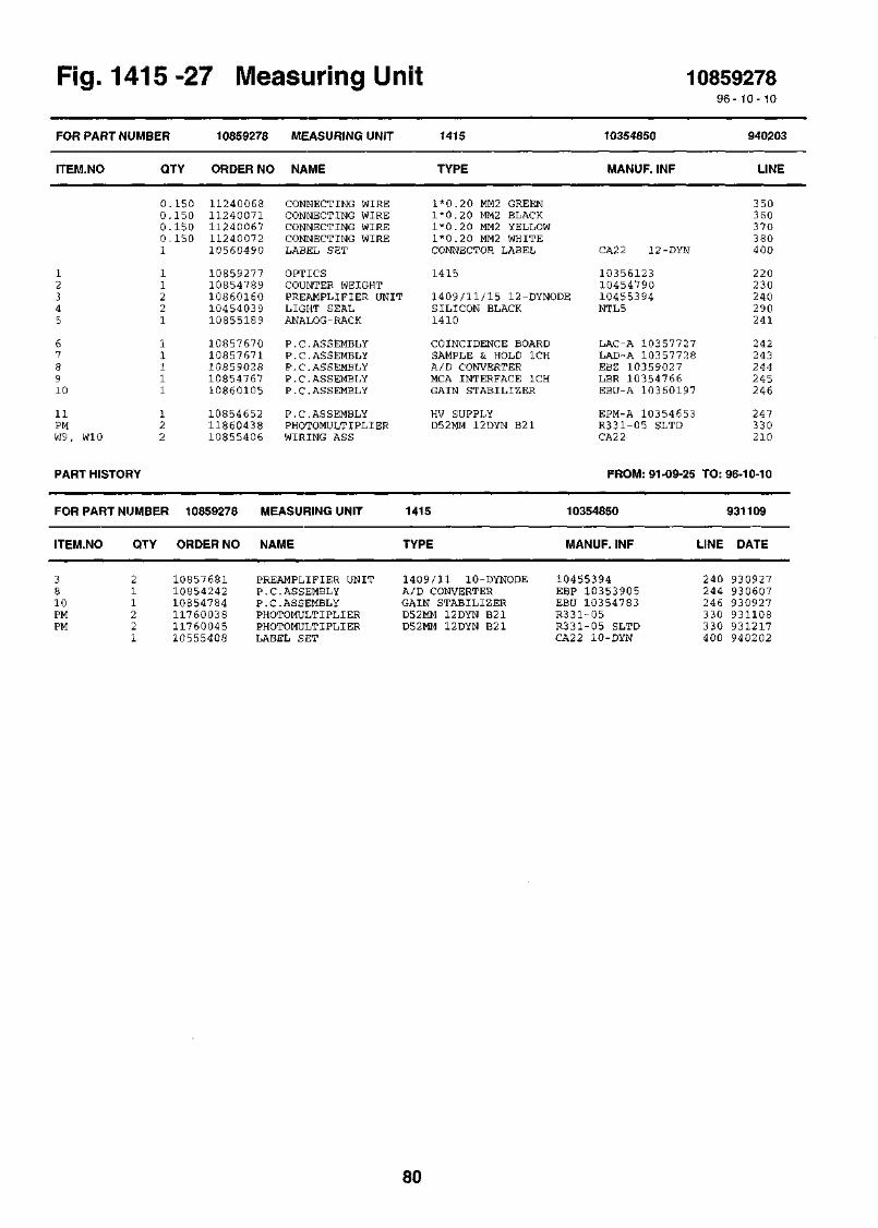
1415 -27 Measuring Unit 1085927896-10- 10
FOR
ITEM
12345
678910
11PMW9,
PART NUMBER 10859278
I.NO QTY ORDER NO
0.0.0.0.1
11221
11111
12
W10 2
PART HISTORY
FOR
ITEM
PART NUMBER
.NO QTY
150 11240068150 11240071150 11240067150 11240072
10560490
1085927710854789108601601045403910855189
1085767010857671108590281085476710860105
108546521186043810855406
MEASURING UNIT
NAME
CONNECTING WIRECONNECTING WIRECONNECTING WIRECONNECTING WIRELABEL SET
OPTICSCOUNTER WEIGHTPREAMPLIFIER UNITLIGHT SEALANALOG-RACK
P.C.ASSEMBLYP.C.ASSEMBLYP.C.ASSEMBLYP.C.ASSEMBLYP.C.ASSEMBLY
P.C.ASSEMBLYPHOTOMULTIPLIERWIRING ASS
10859278 MEASURING UNIT
ORDER NO NAME
1415
TYPE
1*0.20 MM2 GREEN1*0.20 MM2 BLACK1*0.20 MM2 YELLOW1*0.20 MM2 WHITECONNECTOR LABEL
10354850
MANUF. INF
CA22 12-DYN
1415 1035612310454790
1409/11/15 12-DYNODE 10455394SILICON BLACK NTL51410
COINCIDENCE BOARDSAMPLE & HOLD 1CHA/D CONVERTERMCA INTERFACE 1CHGAIN STABILIZER
HV SUPPLYD52MM 12DYN B21
1415
TYPE
LAC-A 10357727LAD-A 10357728EBZ 10359027LBR 10354766EBU-A 10360197
EPM-A 10354653R331-05 SLTDCA22
FROM: 91-09-25 TO:
10354850
MANUF. INF LINE
940203
LINE
350360370380400
220230240290241
242243244245246
247330210
96-10-10
931109
DATE
3810PMPM
211221
108576811085424210854784117600381176004510555408
PREAMPLIFIER UNITP.C.ASSEMBLYP.C.ASSEMBLYPHOTOMULTIPLIERPHOTOMULTIPLIERLABEL SET
1409/11 10-DYNODEA/D CONVERTERGAIN STABILIZERD52MM 12DYN B21D52MM 12DYN B21
10455394EBP 10353905EBU 10354783R331-05R331-05 SLTDCA22 10-DYN
240 930927244 930607246 930927330 931108330 931217400 940202
80

^ooaia. TSQ.
950504 AS
KDfti. 940211MKOU. 9SM1I «H£> 2.104 541IH *HE 22t?
IOTE
= USED ONLY UI5HUOM!
*=KAYTOSSA VAIN U15;stg
* * -LEAD OPTION
10 15 5600-B
LSC U10Piirt.881220 9/5Tark.881220 WaHyw 881220 ^


Fig. 1415 -27 Measuring Unit 10354850
omoo
inCO
o
00OO
81
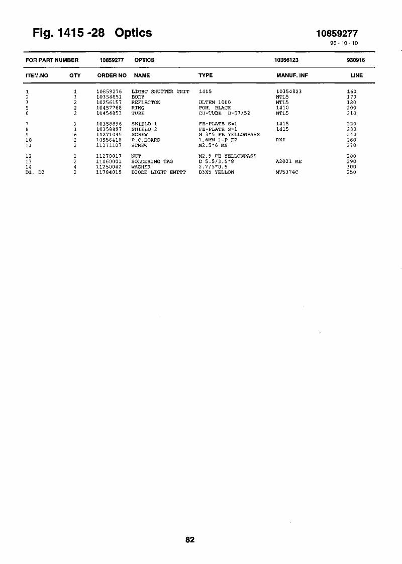
FOR
ITEM
12356
7891011
121314Dl,
ig. 141&
PART NUMBER
.NO QTY
11222
11622
224
D2 2
-28 Uf
10859277
ORDER NO
1085927610354851102561571045776810454853
1035889610358897112710451055641811271107
11278017114600011125004211784015
)tlCS
OPTICS
NAME
LIGHT SHUTTER UNITBODYREFLECTONRINGTUBE
SHIELD 1SHIELD 2SCREWP.C.BOARDSCREW
NUTSOLDERING TAGWASHERDIODE LIGHT EMITT
TYPE
1415
ULTEM 1000POM, BLACKCU-TUBE D=57/52
FE-PLATE S=lFE-PLATE S=lM 3*5 FE YELLOWPASS1,6MM 1-P EPM2.5*6 MS
M2.5 FE YELLOWPASSD 5 . 5 / 3 . 5 * 82 . 7 / 5 * 0 . 5D3X5 YELLOW
10356123
MANUF. INF
10354823NTL5NTL51410NTL5
14151415
RXI
A2021 ME
MV5374C
108592779 6 - 1 0 - 1 0
930916
LINE
160170180200210
220230240260270
280290300250
82

Fig. 1415-28 Optics 10356123
l ainrt-
COCM
CO
o
IT! LT> IT)
83
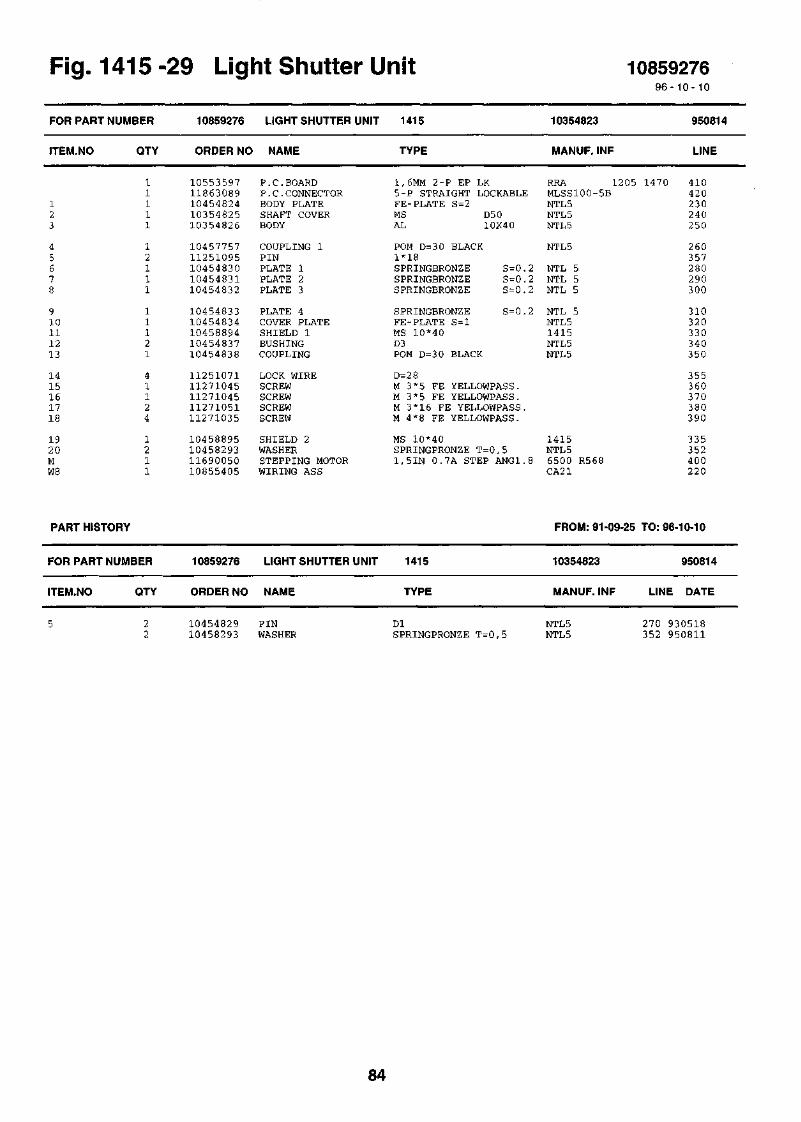
Fig. 1415 -29 Light Shutter Unit 108592769 6 - 1 0 - 10
FOR PART NUMBER 10859276 LIGHT SHUTTER UNIT 1415 10354823 950814
ITEM.NO QTY ORDER NO NAME TYPE MANUF. INF LINE
910111213
1415161718
1920MW8
1055359711863089104548241035482510354826
1045775711251095104548301045483110454832
1045483310454834104588941045483710454838
1125107111271045112710451127105111271035
10458895104582931169005010855405
P.C.BOARDP.C.CONNECTORBODY PLATESHAFT COVERBODY
COUPLING 1PINPLATE 1PLATE 2PLATE 3
PLATE 4COVER PLATESHIELD 1BUSHINGCOUPLING
LOCK WIRESCREWSCREWSCREWSCREW
SHIELD 2WASHERSTEPPING MOTORWIRING ASS
1,6MM 2-P EP LK5-P STRAIGHT LOCKABLEFE-PLATE S=2MS D50AL 10X40
POM D=3 0 BLACK1*18SPRINGBRONZE S=0.2SPRINGBRONZE S = 0.2SPRINGBRONZE S = 0.2
SPRINGBRONZE S=0.2FE-PLATE S=lMS 10*40D3POM D=30 BLACK
D=28M 3*5 FE YELLOWPASS.M 3*5 FE YELLOWPASS.M 3*16 FE YELLOWPASS.M 4*8 FE YELLOWPASS.
MS 10*40SPRINGPRONZE T=0,51,5IN 0.7A STEP ANG1.8
RRA 1205 1470MLSS100-5BNTL5NTL5NTL5
NTL5
NTL 5NTL 5NTL 5
NTL 5NTL 51415NTL 5NTL5
1415NTL 56500 R568CA21
410420230240250
260357280290300
310320330340350
355360370380390
335352400220
PART HISTORY FROM: 91-09-25 TO: 96-10-10
FOR PART NUMBER 10859276 LIGHT SHUTTER UNIT 1415 10354823 950814
ITEM.NO QTY ORDER NO NAME TYPE MANUF. INF LINE DATE
10454829 PIN10458293 WASHER
DlSPRINGPRONZE T=0,5
NTL5NTL5
270 930518352 950811
84

Fig. 1415 -29 Light Shutter Unit 10354823
ME: t e w e i o e u ASME: 1914. 910910 «HE: 193C 9*052.1 nME. 2113 916111 If.
10 35 4823
85
Pi irt. 881108Tark. 881108 tVa.Hyv. 881108 &

Fig. -30 Top Cover Assembly 1085927996 -10 -10
FOR
ITEM
12345
678910
1112131415
1617181921
2224262729
3031323334
3536383940
414243444546
PART NUMBER
I.NO QTY
11112
22112
22211
11621
11
121
12
16421
21624
421112
PART HISTORY
FOR
ITEM,
PART NUMBER
NO QTY
10859279
ORDER NO
1139102610355463103554671035547010455473
1045547410255475103554761035547710455000
1045547810455479104554801025548110254553
1035548810355489104554901045549110455493
1035549410855453112500101125101511274012
1127408811274133112741341127603010455763
1127601510456094112500411129001310456181
112740311125003910358879104599781045997911274004
TOP COVER ASSEMBLY 1415
NAME
GAS SPRINGPLATE RIGHT, ASS.PLATE LEFT ASS.SUPPORT BOX ASS.PLATE
PLATESUPPORTHINGE BODY RIGHTHINGE BODY LEFTSPRING
GUIDEPLATEBRACKETTOP COVERCOVER
HINGE RIGHTHINGE LEFTNUTPINPLATE
HANDLEINSULATION SETWASHERPINSCREW
SCREWSCREWSCREWSCREWCOVER ASSEMBLY
SCREWEDGE STRIPWASHERFOOTWASHER
SCREWWASHERSHIELD ASSEMBLYEXTENSION ARMMOUNTING PINSCREW
10859279 TOP COVER ASSEMBLY
ORDER NO NAME
TYPE
FJ-DER
FE-PLATE S=l,5
FE-PLATE S=3AL-PLATE 10X2 5FE-PLATE S=l,5FE-PLATE S=l,5D2
D6H8POM BLACK D=12
PLATE S=5
FE-PLATE S=l,5FE-PLATE S=l,5MS D18D2,5POM-PLATE S=8
POM-PLATE S=25
5.3/10*1 FE YELLOWPASS.2*10 STM5*10 FE YELLOWPASS.
M3*20 FE YELLOWPASS.M4*6 FE BLACKPASS.M5*10 FE BLACKPASS.B4.2*22 FE YELLOWPASS.
B 2.9*6.5 FE YELLOWPASSFE-PLATE T=l4.3/9*0.8 FE BLACKD12*3 RUBBER WHITEFE-PLATE T=2
M5*12 FE YELLOWPASS.4.3/12*1 FE YELLOWPASS.FE-PLATE/LEAD CASTMS D=8MS-ROD D10M4*6 FE YELLOWPASS.
10255462
MANUF. INF
16-1-168-135-60NTL5NTL5NTL5NTL5
NTL5NTL5NTL5NTL5NTL5
NTL5NTL5NTL5NTL5NTL5
NTL5NTL5NTL5NTL5NTL5
NTL5NTL5
NTL5
NTL5
3M SJ 5012LSC5
141514091409
FROM: 91-09-25 TO:
1415 10255462
TYPE MANUF. INF LINE
940623
LINE
745530540550560
570580590600610
620630640650660
670680690700720
730520760770790
800810820830731
840741860870742
850750655510515805
96-10-10
940623
DATE
17402941
112
142
1085544510255475104561811127401211274004
SPRING ASSEMBLYSUPPORTWASHERSCREWSCREW
10455446 NTL5AL-PLATE 10X25 NTL5FE-PLATE T=2 LSC5M5*10 FE YELLOWPASS.M4*6 FE YELLOWPASS.
510 930812580 940607742 940607790 940607805 940622
86

Fig. 1415 -30 Top Cover Assembly 10255462
n. raa e&iaao TUS
Me;1983 9305O3 A4KM)«0!. 931Z05HIME 119? 9V0fcl3*4
* - KAYTOSSA VAIN H15.stg
10 25 5462
87Piirt. 881109 -THsTork.881109 rtla.Hyv. 881109 £<£

Fig. 1415-31 Guard 108589149 6 - 1 0 - 10
FOR PART
ITEM.NO
NUMBER
QTY
10858914
ORDER NO
GUARD
NAME
1415
TYPE
10458913
MANUF. INF
930915
LINE
110 .5500 . 1 2 500 .0071
10358909102589021109001111091022111200191112001810460181
LIDGUARD TANKSOLVENTSILICONE RUBBERSECONDARY SCINTILLPRIMARY SCINTILLATSEAL
CU S=0.5ASSEMBLYDOBANE 1032-KOMP., CLEARQUALITYQUALITYD50*3 POM
14151415DOBANE 103RTV 615BIS-MSBPPO1415
1020708090
1 0 0110
PART HISTORY FROM: 91-09-25 TO: 96-10-10
FOR PART NUMBER 10858914 GUARD 1415 10458913 950424
ITEM.NO QTY ORDER NO NAME TYPE MANUF. INF LINE DATE
0.500 11091022 SILICONE RUBBER 2-KOMP., CLEAR RTV 615 80 950421
88

Fig. 1415-31 Guard 10458913
Korj.rra 11 080993 MVa
10458913
Piirt 29/01 1993 MVnTurk 29/01 1993 MVaHyv 29/01 1993 KLo
89

Fig. HV-Divider Unit 1085936996-10- 10
FOR PART
ITEM.NO
NUMBER
QTY
10859369
ORDER NO
HV-DIVIDER UNIT
NAME
RFA
TYPE
10359368, 10355373
MANUF. INF
960607
LINE
1234
56789
1011121314
15ClC2-5RlR2
R3-7,10-14,1R8,15,22,29R9,16,23,30R31-34Sl-8
11541.090
11321
11236
38124
11411
204441.111
1186000111460001112500211125000111240035
1055402410358910104548361126003510454401
1054457611310006113201061127101811271019
1127102311278002105565681148004711273013
1046195111626002116260081160114911604049
1160424111604225116038681160420911863070
COAXIAL CONNECTORSOLDERING TAGSERRAT LOCK WASHERWASHERCOAXIAL CABLE
P.C.BOARDPLATENUTRISE PINBOX
LABELCLAMPLOCK. CARD SPACERSCREWSCREW
SCREWNUTLABELFERRITE CLAMPSCREW
INSULATOR PLATECAPACITOR H.V.CAPACITOR H.V.RESISTORRESISTOR MF SM
RESISTOR MF SMRESISTOR MF SMHV RESISTORRESISTOR MF SMP.C.CONNECTOR
D 5.5/3.5*83.0 ANNEALED ZINKEDA3, 2
1,6MM 2-P EP LKFE- PLATE S=lMS 6K6M3*10 MSABS S=2
MS 1.25 MKLNYLONM 3*6 FE YELLOWPASS.M 3*8 FE YELLOWPASS.
M 3*14 FE YELLOWPASS.M3 FE YELLOWPASS.WHITE-SELF-ADHESIVE-LD 6,6 MMM2 .5*4 FE BLACK
PRESPAN S=0,52.5NF 3KV150PF 3.0KV 20/50%10K 2% 0.5W100 1% 0,125W 100PPM
l,0OM 1% 0,125W 100PPM464K 1% 0,125W 100PPM22Mohm 5% 0.5W 3.5kVDC215K 1% 0,125W 100PPM40-PIN STRAIGHT
11H4-50-3-1A2021 ME3.2*5.5*0.45
RG-58 C/U
RRH 14101415NTL55.03.1031205
DANGER H.V. SERIVAA 3 024 ASAKGLS-3S
HV-OUTPUT-INPUT28B2025-OAO
DD3 0 2529/0130.9 D FERROPB 1/2 BEYSCHLAGCRCW1206
CRCW1206CRCW1206232224213226CRCW1206SL1/25/36G
30110190200210
230260240180250
270130120170160
150140220115135
280504010090
6070958020
90
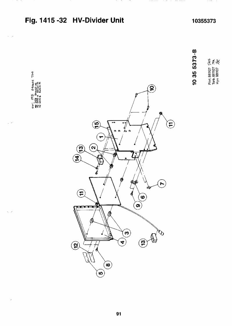
Fig. 1415 -32 HV-Divider Unit 10355373
ai -
OQi
CONiCOLOLOCO
COCO
c
91

i-ig. T41t> -
FOR PART NUMBER
ITEM.NO
12346
89121314
1516171819
2021222324
25262728W25
W2 6W33
PART HISTORY
QTY
11112
41221
11296
28121
10.05010.8501
11
FOR PART NUMBER
ITEM.NO
7W57
118
QTY
15154
112
33 UIJ
10859287
ORDER NO
1085466510854760102592831184203611250001
1127800210557386114800491148005011240162
1036169110361690104616891127601511271021
1127102611250044112710181125000610861635
1086163811180017104536971122001410851794
1085559210861704
10859287
ORDER NO
1085562811271030108517941045561911271030
1127102911278002
spiay unit
DISPLAY UNIT
NAME
P.C.ASSEMBLYP.C.ASSEMBLYBOXTOUCH PANELWASHER
NUTLABELFERRITE CLAMPCLAMPRF GASKET
LID ASSEMBLYBOX ASSEMBLYBUSHINGSCREWSCREW
SCREWWASHERSCREWWASHERP.C.ASSEMBLY
P.C.ASSEMBLYPE-STRINGINSULATOR PLATETAPEFLAT CABLE
FLAT CABLEFLAT CABLE
DISPLAY UNIT
NAME
PROGRAM PACKAGESCREWFLAT CABLEBUSHINGSCREW
SCREWNUT
1415
TYPE
DISPLAYDISPLAY (CPU)ASSEMBLY
A3, 2
M3 FE YELLOWPASS.PVC FASKAL-400 T=0,l2 6-WIRE FLAT CABLEFOR 26-W.FLAT C. CLAPM3,2X4,8 MONEL
TIN COVEREDTIN COVEREDMSC 2.9*6.5 FE YELLOWPASSM 3*10 FE YELLOWPASS.
M 3*18 FE YELLOWPASS.3.2/9*0.8 FE YELLOWPASSM 3*6 FE YELLOWPASS.3.2/7*0.5 FE YELLOWPASSFILTER BOARD
FILTER BOARD5*5, BLACKPRESPAN S=0,512MM CLEAR26S-26S
50S-50S34S-34S
1415
TYPE
10355598
MANUF. INF
HDG 10254761HCB 103547591415010377
1410 RESET28B2022-000M-CLIP01-0901-6601
NTL-5NTL-5NTL-5
RYP
RYQPZ-940 SJH1205TESA4 97110451797
1085928796- 10-10
960612
LINE
510520540550570
590600610620630
640650660670680
690700710720
10461634 525
10461637 535730740750530
FC35 10455666 533FC220 10461703 537
FROM: 91-09-25 TO: 96-10-10
10355598
MANUF. INF
DISPLAY PRG. HCB-BOARDM3*3 5 FE YELLOWPASS26S-26S 10451797MS D6/4 NTL5M 3*35 FE YELLOWPASS.
M 3*30 FE YELLOWPASS.M3 FE YELLOWPASS.
960612
LINE DATE
521 930825580 940405530 960213560 960115580 960115
585 960115590 960112
92

Fig. 1415-33 Display Unit 10355598
!i±J|^h
93

94

1414 Supplement
95

96

1414 Wint:
FOR PART NUMBER
ITEM.NO QTY
11110.500
11
10160809-120 1
>pecm
1414-001
ORDER NO
108606781410-4051410-4011409-4111200-437
1414-1601085588410860862
11
WIN SPECTRAL
NAME
WINSPECTRALSAMPLE TRAYRACKS, 20 MLID KITOPTIPHASE'HISAFE"3
MONITOR STANDPACKAGEKEYBANK ASSEMBLY
1414-001
TYPE
1414-001FOR SAMPLE RACKSPACKAGE OF 10 RACKS1409-4112X5 L
600 MM / 230 MM104558851414
MANUF. INF
101608091410-4051410-401
1200-437
141010260855
1414-0019 6 - 1 0 - 1 0
960805
LINE
10110120130140
150170160
»-ig. i
FOR PART
ITEM.NO
12345
678910
1112131415
1617181920
1414 -3
NUMBER
QTY
11110 . 3 0 0
0 . 7 0 01111
10 . 3 0 0111
51111
11111
11111
21111
12212
4 wir
10860678
ORDER NO
1085765310856730108552721086109110856077
1085607810446545105555091055612610551111
1056049010561102105613481056161411310040
113100371215-1111224-5131414-93110990045
1086080410855818108553381085484910859369
1086080610856466108548841085460610853316
1085402110360749103613691036077410360773
1036075210455328104588901045533010455329
\ ^peciras
WIN SPECTRAL
NAME
P.C.ASSEMBLYDCD EXPANSION KITEXTERNAL STANDARDSTD. CAPSULEINSTALL. KIT 115V
INSTALL.KIT 250VFOOTLABEL SETLABELLABEL
LABEL SETLABELLABELLABELCLAMP
CLAMPUNQ.STANDARDS SETSOFTWARE PACKAGEINSTRUMENT MANUALQC CERTIFICATE
BODY ASSEMBLYID-UNITSAMPLE CHANGERMEASURING UNITP.C.ASSEMBLY
TOP COVER ASSEMBLYP.C.ASSEMBLYP.C.ASSEMBLYP . C. ASSEMBLYP . C. ASSEMBLY
P . C. ASSEMBLYFRONT PANEL RIGHTBOX ASSEMBLYSIDE BOX RIGHTSIDE BOX LEFT
FRONT PLATE LEFTCAMGUIDE PLATEBUSHINGPLATE
1414-001
TYPE
SW KEY MODULE BOARD
FOR 1410
FOR 1410PAG, BLACK, 3 0% GLAS
VME RACKCSA-APPROVED (ALO,08)
WARNING STICK, BRADYPATENTS, BRADY -LABEL11570078 (BRADY)
20ML VIALS 3H/14C/BACK1414 WINSPECTRALFOR 1 4 1 4 - 0 0 1
1414141014101410HV-DIVIDER UNIT
1414MICRO COMPUTERI / O BOARDMCAPOWER SUPPLY
MOTOR CONTROL BOARD
FE PLATE S = 1 . 0FE PLATE S = 1 . 0
D2 5FE-PLATE S=3D12FE-PLATE S=3
1086067896- 10- 10
10160809 960404
MANUF. INF
RJG 10457652DCD 103564651025527310361101 1400-SERIES
1215,1470FC33,FC2071410(LR52500) BRADY
CA22 12-DYNEU-152 10561102.LABSTD B/PLATECE -LABELACC62-A
FCC-A-C81215-1111224-5131414-93110990045
10160805103558591025533910354850RFA103 593 68,10355373
10260807DCD 10356465DIC 10354883DIE 10354603DPA 10353503
HPS 103540221414141414141414
1414NTL51415NTL5,1470NTL5
LINE
110121122123124
125408412414416
420422427429586
5871000101010201030
1011152535
4555657 585
95146130135145
147175205195185
97

2122232425
2627282930
3233343536
3738394041
4243444546
4748495051
5253545556
5759606162
6364656667
6869707172
7374757677
101102105106115
116117118119122
123124126141142
143144145146147
148149
12211
41111
11111
11112
15101
184
42864
102261
103288
12111
12112
12111
212241
11261
22212
122.30026
11
1035533210455333104553341035533510255612
1045561610355617103556181045563210355742
1036074411710021104607431055567210494512
1054812210355677103556861045572310455797
1125000811250010112500191125101811251045
1125107711252008112520191127101611271034
1127401311274016112740341127414511274095
1127413911250018104551311127103611278003
1045589711271095105560701055609510556071
1045618211274003104563821055660710457299
1045730011276015108607101045889810458899
1125003911274004113100471129001510860713
1046076210460761112500061127400210460964
1127105311274156105606561086141010461276
1046141411240173112401621046148011276022
1055738610461613
LEADLEADLEADHANDLE 1BACK PLATE
BUSHINGINSULATIONCOVER 1COVER 2COVER 3
LID ASSEMBLYFLOPPY DISK DRIVEHANDLELABELWARNING PLATE
LABELSUPPORTCOVERBUSHINGSHIELD
WASHERWASHERWASHERPINLOCKRING
LOCKRINGRIVETRIVETSCREWSCREW
SCREWSCREWSCREWSCREWSCREW
SCREWWASHERCOOLING PLATESCREWNUT
PLATESCREWLABELLABELLABEL
PLATESCREWINSULATIONLABELBRACKET
GUIDESCREWRESET UNITBRACKET RIGHTBRACKET LEFT
WASHERSCREWNUTBODDUMMY PLUG
PLATE RIGHTPLATE LEFTWASHERSCREWSHELTER
SCREWSCREWLABELP.C.ASSEMBLYHOLDER
SUPPORT 1RF GASKETRF GASKETPLATESCREW
LABELHOLDER
LEAD 99.9%LEAD 99.9%LEAD 99.9%FE-PLATE S=2FE-PLATE S=l
MS D=20SOLUPOLYETHENAL-PLATE S=2FE-PLATE S=2AL-PLATE S=2
3,5"2-P 80U/P500/250KBAL SQUARE BAR 8.2x8.2AL 99.5 S=lAL-PLATE S = 0, 5
0, 5MMAL-PLATE S=2FE-PLATE S=lPOM-ROD D=40MU S=0,l
4.3/9*0.8 FE YELLOWPASS.5.3/10*1 FE YELLOWPASS.6.4/18*1.6 FE,ZINKED3*20 ST13*1
16*11.9*3 ST2.4*5.1 ALM 3*4 FE YELLOWPASS.M 4*5 FE YELLOWPASS.
M 5*12 FE YELLOWPASS.M 5*2 0 FE YELLOWPASS.M 6*3 0 FE YELLOWPASS.M6*12 FE YELLOWPASS.M6*25 YELLOWPASS.
M4*8 FE BLACKPASS.5.3/15*1.6 FE YELLOWPASSAL-PLATE S=3M 4*10 FE YELLOWPASS.M4 FE YELLOWPASS.
FE-PLATE S=lM6*12 FE YELLOWPASS.HVAL0,08AL S=0,08
FE-PLATE T=lM 3*10 FE YELLOWPASS.SOLUPOLYETHEN S=20WHITE-SELF-ADHESIVE-LFE-PLATE T=l
FE-PLATE T=lC 2.9*6.5 FE YELLOWPASS.
FE S = lFE S = l
4.3/12*1 FE, ZINKEDM 4*6 FE YELLOWPASS.M4 1,7-2,7D4,8*4,41414
FE PLATE S=2.0FE PLATE S=2.03.2/7*0.5 FE YELLOWPASS.M 3*6 FE YELLOWPASS.POM-PLATE S=8, BLACK
M4*8 FE YELLOWPASS.M6*16 ST YELLOWPASS.ST.POLYESTER 11570076CONNECTION BOARDFE S=l NICKELIZED
FE PLATE S = 1.06,35x6,35 MONEL, GLUE3,2X4,8 MONEL
C 2.9*9.5 FE YELLOWPASS.
PVC FASKAL-400 T=0,lFE-PLATE T=l
NTL-5NTL-5NTL-5NTL5NTL5
NTL5
NTL 5NTL 5NTL5
1414FD1137H1414NTL5
NTL5NTL5NTL 5NTL 5
KDS 0*3TAP/D/BS 33
NTL5
NTL5
1410 WARNING1410 CR1410 PROGRAM CR
LSC-5
NTL-5NOTE !LSC
LSC
102556791409/11/151409/11/15
14.08.0401414 10460712
14141414
NTL 5
MACH.LABEL 1414-001RGE 10461408
141401-0901-660301-0901-66011414
1410 'RESET'1409
210230240250265
275285295305306
148425149415423
421375385395403
430431435445455
465475485495505
515525535545555
565434326510585
327511417418419
404514409413328
329576119400401
440513590426120
150151432566402
490530411114350
340600610360570
428355
98

10260807-2310260807-3710355819-17
10355819-4310355819-44W24W3 2
PART HISTORY
111
1111
FOR PART NUMBER
ITEM.NO QTY
103606571157006110355762
10457903103579021086134610861411
10860678
ORDER NO
COVER PLATELABELID-SHIELD
PLATESUPPORTFLAT CABLEWIRING ASS
WINSPECTRAL
NAME
POLYCARB.0.375WALLAC 52X22,16STICKERFE-PLATE S=l
ST-PLATE T = l , 5RST. T=0 ,840S-40S
1414-001
TYPE
1414
NTL 5
410424405
1410 4061410 407FC207 10461300 117CA210 115
FROM: 91-09-25
10160809
MANUF. INF
TO: 96-10-10
960404
LINE DATE
147 11276022 SCREW C 2.9*9.5 FE YELLOWPASS. 570 960403
1414 Alpha/Beta 1414-00296-10- 10
FOR PART
ITEM.NO
NUMBER
QTY
1414-002
ORDER NO
ALPHA/BETA
NAME
1414-002
TYPE MANUF. INF
960620
LINE
10160809-120
1 10861383 ALFABETA1 1410-405 SAMPLE TRAY1 1410-401 RACKS, 20 ML1 1409-411 ID KIT0.500 1200-437 OPTIPHASE"HISAFE"3
1 1414-160 MONITOR STAND1 10859610 PACKAGE1 1411-302 PC-PROGRAM PACKAGE1 1224-533 PC-PROGRAM1 10860862 KEYBANK ASSEMBLY
1414-002 10160809FOR SAMPLE RACKS 1410-405PACKAGE OF 10 RACKS 1410-4011409-4112X5 L 1200-437
600 MM / 230 MM1415 10459611SPECTRUM ANALYSIS PRG.EASY SCAN 1224-5331414 10260855
10110120130140
150170180190160
m
FOR
ITEM
12345
g .1414 -a
PART NUMBER
.NO QTY
11110 . 3 0 0
0 . 7 0 01111
10 . 3 0 0111
51111
11111
4 Alp
10861383
ORDER NO
1085765310856730108552721086109110856077
1085607810446545105555091055612610551111
1056049010561102105613481056161411310040
113100371215-1111224-5131414-93210990045
1086080410855818108553381085927810859369
na/aeia
ALPHA/BETA
NAME
P.C.ASSEMBLYDCD EXPANSION KITEXTERNAL STANDARDSTD. CAPSULEINSTALL. KIT 115V
INSTALL.KIT 250VFOOTLABEL SETLABELLABEL
LABEL SETLABELLABELLABELCLAMP
CLAMPUNQ.STANDARDS SETSOFTWARE PACKAGEINSTRUMENT MANUALQC CERTIFICATE
BODY ASSEMBLYID-UNITSAMPLE CHANGERMEASURING UNITP.C.ASSEMBLY
1414-002
TYPE
SW KEY MODULE BOARD
FOR 1410
FOR 1410PAG, BLACK, 3 0% GLAS
VME RACKCSA-APPROVED (ALO,08)
WARNING STICK, BRADYPATENTS, BRADY -LABEL11570078 (BRADY)
20ML VIALS 3H/14C/BACK1414 WINSPECTRALFOR 1 4 1 4 - 0 0 2 / 1 4 1 4 - 0 0 3
1414141014101415HV-DIVIDER UNIT
1086138396- 10- 10
10160809 960404
MANUF. INF
RJG 10457652DCD 103564651025527310361101 1400-SERIES
1215,1470FC33,FC2071410(LR52500) BRADY
CA22 12-DYNEU-152 10561102.LABSTD B/PLATECE -LABELACC62-A
FCC-A-C81215-1111224-5131414-93210990045
10160805103558591025533910354850RFA10359368,10355373
LINE
110121122123124
125408412414416
420422427429586
5871000101010201030
1011152535
99
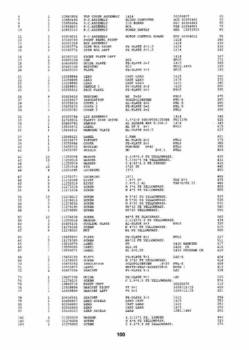
678910
1112131415
1617181920
2122232425
2627282930
3233343536
3738394041
4243444546
4748495051
5253545556
5759606162
6364656667
6869707172
7374757677
7879818283
101102103
11111
21111
12212
12211
41111
11111
11112
15101
264
42864
102261
103288
12111
12112
12111
11111
4122
1086080610856466108548841085460610853316
1085402110360749103613691036077410360773
1036075210455328104588901045533010455329
1035888410358885103588861045889310255612
1045561610355617103556181045563210355742
1036074411710021104607431055567210494512
1054812210355677103556861045572310455797
1125000811250010112500191125101811251045
1125107711252008112520191127101611271034
1127401311274016112740341127414511274095
1127413911250018104551311127103611278003
1045589711271095105560701055609510556071
1045618211274003104563821055660710457299
1045730011276015108607101045889810458899
1045889110458887103588891035888810448323
112500391127400411276005
TOP COVER ASSEMBLYP. C. ASSEMBLYP.C.ASSEMBLYP.C.ASSEMBLYP. C. ASSEMBLY
P.C.ASSEMBLYFRONT PANEL RIGHTBOX ASSEMBLYSIDE BOX RIGHTSIDE BOX LEFT
FRONT PLATE LEFTCAMGUIDE PLATEBUSHINGPLATE
LEADLEADLEADHANDLE 2BACK PLATE
BUSHINGINSULATIONCOVER 1COVER 2COVER 3
LID ASSEMBLYFLOPPY DISK DRIVEHANDLELABELWARNING PLATE
LABELSUPPORTCOVERBUSHINGSHIELD
WASHERWASHERWASHERPINLOCKRING
LOCKRINGRIVETRIVETSCREWSCREW
SCREWSCREWSCREWSCREWSCREW
SCREWWASHERCOOLING PLATESCREWNUT
PLATESCREWLABELLABELLABEL
PLATESCREWINSULATIONLABELBRACKET
GUIDESCREWRESET UNITBRACKET RIGHTBRACKET LEFT
BRACKETLEAD SHIELDLEADLEADLEAD SHIELD
WASHERSCREWSCREW
1414MICRO COMPUTERI/O BOARDMCAPOWER SUPPLY
MOTOR CONTROL BOARD
FE PLATE S=l.0FE PLATE S=1.0
D25FE-PLATE S=3D12FE-PLATE S=3
CAST LEADCAST LEADCAST LEADFE-PLATE S=2FE-PLATE S=l
MS D=2 0SOLUPOLYETHENAL-PLATE S=2FE-PLATE D=2AL-PLATE S=2
3,5"2-P 80U/P500/250KBAL SQUARE BAR 8.2x8.2AL 99.5 S=lAL-PLATE S=0,5
0, 5MMAL-PLATE S=2FE-PLATE S=lPOM-ROD D=40MU S=0,l
4.3/9*0.8 FE YELLOWPASS.5.3/10*1 FE YELLOWPASS.6.4/18*1.6 FE,ZINKED3*20 ST13*1
16*11.9*3 ST2.4*5.1 ALM 3*4 FE YELLOWPASS.M 4*5 FE YELLOWPASS.
M 5*12 FE YELLOWPASS.M 5*2 0 FE YELLOWPASS.M 6*3 0 FE YELLOWPASS.M6*12 FE YELLOWPASS.M6*25 YELLOWPASS.
M4*8 FE BLACKPASS.5.3/15*1.6 FE YELLOWPASSAL-PLATE S=3M 4*10 FE YELLOWPASS.M4 FE YELLOWPASS.
FE-PLATE S=lM6*12 FE YELLOWPASS.HVAL0,08AL S=0,08
FE-PLATE T=lM 3*10 FE YELLOWPASS.SOLUPOLYETHEN .S=20WHITE-SELF-ADHESIVE-LFE-PLATE T=l
FE-PLATE T=lC 2.9*6.5 FE YELLOWPASS.
FE S = lFE S = l
FE-PLATE S=lLEAD CASTCAST LEADCAST LEADLEAD
4.3/12*1 FE, ZINKEDM 4*6 FE YELLOWPASS.C 4.2*9.5 FE YELLOWPASS.
10260807DCD 10356465DIC 10354883DIE 10354603DPA 10353503
HPS 103540221414141414141414
1414NTL51415NTL5,1470NTL5
1415141514151415NTL5
NTL5NTL-5NTL 5NTL 5NTL5
1414FD1137H1414NTL5
NTL5NTL5NTL5NTL 5
KDS 0*3TAP/D/BS 33
NTL5
NTL5
1410 WARNING1410 CR1410 PROGRAM CR
LSC-5
NTL-5NOTE !LSC
LSC
102556791409/11/151409/11/15
14151415141514151282,1480
4555657585
95146130135145
147175205195185
210230240250265
275285295305306
148425149415423
421375385395403
430431435445455
465475485495505
515525535545555
565434326510585
327511417418419
404514409413328
329576119400401
254253251252255
440513570
100

104105106115116
117118119122123
124126127128141
142143144145146
14714814910260807-4310260807-23
10260807-3710260807-4210260807-4110260807-4810355819-17
10355819-4310355819-44W24W32
22411
12612
22221
2122.3002
61111
14221
1111
1127401011310047112900151086071310460762
1046076111250006112740021046096411271053
1127415610561339104613781036137910861410
1046127610461414112401731124016210461480
1127602210557386104616131035887910361030
1157006111250039112740061127602610355762
10457903103579021086134610861411
SCREWNUTBODDUMMY PLUGPLATE RIGHT
PLATE LEFTWASHERSCREWSHELTERSCREW
SCREWLABELLEAD SHIELDSUPPORTP.C.ASSEMBLY
HOLDERSUPPORT 1RF GASKETRF GASKETPLATE
SCREWLABELHOLDERSHIELD ASSEMBLYCOVER PLATE 2
LABELWASHERSCREWSCREWID-SHIELD
PLATESUPPORTFLAT CABLEWIRING ASS
M 4*2 5 FE YELLOWPASS.M4 1,7-2,7D4,8*4,41414FE PLATE S=2.0
FE PLATE S=2.03.2/7*0.5 FE YELLOWPASSM 3*6 FE YELLOWPASS.POM-PLATE S=8, BLACKM4*8 FE YELLOWPASS.
M6*16 ST YELLOWPASS.ST.POLYESTER 11570076LEAD 99.9 %FE-PLATE=2CONNECTION BOARD
FE-PLATE S=l NICKELIZEDFE PLATE S=1.06,3 5x6,3 5 MONEL, GLUE3,2X4,8 MONEL
C 2.9*9.5 FE YELLOWPASSPVC FASKAL-400 T=0,lFE-PLATE T=lFE-PLATE/LEAD CASTPOLYCARB.0.375
WALLAC 52X22,16STICKER4.3/12*1 FE, ZINKEDM 4*10 FE YELLOWPASS.C 3.9*9.5 FEFE-PLATE S=l
ST-PLATE T=l,5RST. T=0,840S-40S
14.08.0401414 104607121414
1414
NTL 5
MACH.LABEL 1414-0021414-0021414-002RGE 10461408
141401-0901-660301-0901-66011414
1410 'RESET'140914151414
NTL 5
14101410FC207 10461300CA210
512590426120150
151432566402490
530411256257114
350340600610360
580428355270410
424441486567405
406407117115
PART HISTORY FROM: 91-09-25 TO: 96-10-10
FOR PART NUMBER 10861383 ALPHA/BETA 1414-001 10160809 960404
ITEM.NO QTY ORDER NO NAME TYPE MANUF. INF LINE DATE
W2 6147
1 10855592 FLAT CABLE4 11276022 SCREW1 1414-102 PC-PROGRAM PACKAGE1 1414-931 INSTRUMENT MANUAL
50S-50S FC35 10455666 118 951128C 2.9*9.5 FE YELLOWPASS. 580 960403PSA+SPECT.ANALYS.PRG. 1414-102 1015 960402FOR 1414-001 1414-931 1020 951201
101
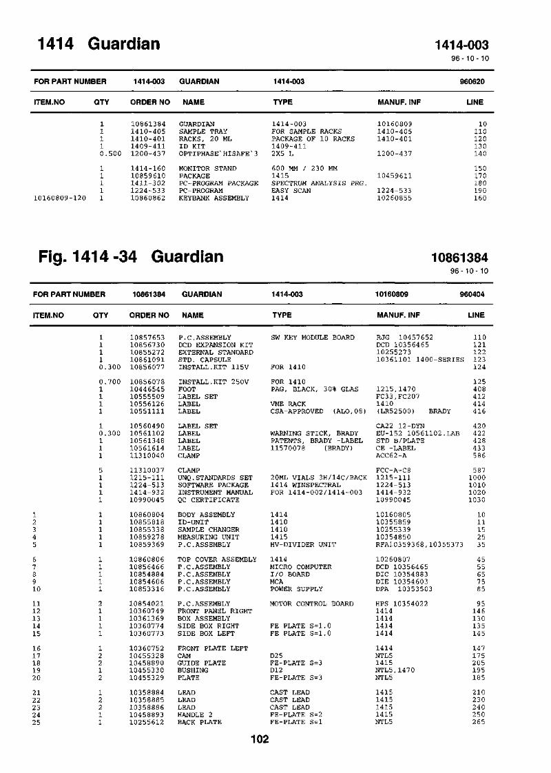
1414 Guardian 1414-0039 6 - 1 0 - 10
FOR PART
ITEM.NO
NUMBER
QTY
1414-003
ORDER NO
GUARDIAN
NAME
1414-003
TYPE MANUF. INF
960620
LINE
10160809-120
1 10861384 GUARDIAN1 1410-405 SAMPLE TRAY1 1410-401 RACKS, 20 ML1 1409-411 ID KIT0.500 1200-437 OPTIPHASE'HISAFE*3
1 1414-160 MONITOR STAND1 10859610 PACKAGE1 1411-302 PC-PROGRAM PACKAGE1 1224-533 PC-PROGRAM1 10860862 KEYBANK ASSEMBLY
1414-003 10160809FOR SAMPLE RACKS 1410-405PACKAGE OF 10 RACKS 1410-4011409-4112X5 L 1200-437
600 MM / 230 MM1415 10459611SPECTRUM ANALYSIS PRG.EASY SCAN 1224-5331414 10260855
10110120130140
150170180190160
Fig. 1414-34 Guardian 1086138496-10-10
FOR PART NUMBER 10861384 GUARDIAN 1414-003 10160809 960404
ITEM.NO QTY ORDER NO NAME TYPE MANUF. INF LINE
12345
678910
1112131415
1617181920
2122232425
11110.300
0.7001111
10.300111
51111
11111
11111
21111
12212
12211
1085765310856730108552721086109110856077
1085607810446545105555091055612610551111
1056049010561102105613481056161411310040
113100371215-1111224-5131414-93210990045
1086080410855818108553381085927810859369
1086080610856466108548841085460610853316
1085402110360749103613691036077410360773
1036075210455328104588901045533010455329
1035888410358885103588861045889310255612
P.C.ASSEMBLYDCD EXPANSION KITEXTERNAL STANDARDSTD. CAPSULEINSTALL.KIT 115V
INSTALL.KIT 250VFOOTLABEL SETLABELLABEL
LABEL SETLABELLABELLABELCLAMP
CLAMPUNQ.STANDARDS SETSOFTWARE PACKAGEINSTRUMENT MANUALQC CERTIFICATE
BODY ASSEMBLYID-UNITSAMPLE CHANGERMEASURING UNITP. C. ASSEMBLY
TOP COVER ASSEMBLYP.C.ASSEMBLYP.C.ASSEMBLYP. C. ASSEMBLYP.C.ASSEMBLY
P.C.ASSEMBLYFRONT PANEL RIGHTBOX ASSEMBLYSIDE BOX RIGHTSIDE BOX LEFT
FRONT PLATE LEFTCAMGUIDE PLATEBUSHINGPLATE
LEADLEADLEADHANDLE 2BACK PLATE
SW KEY MODULE BOARD
FOR 1410
FOR 1410PAG, BLACK, 30% GLAS
VME RACKCSA-APPROVED (ALO,08)
WARNING STICK, BRADYPATENTS, BRADY -LABEL11570078 (BRADY)
20ML VIALS 3H/14C/BACK1414 WINSPECTRALFOR 1414-002/1414-003
1414141014101415HV-DIVIDER UNIT
1414MICRO COMPUTERI/O BOARDMCAPOWER SUPPLY
MOTOR CONTROL BOARD
FE PLATE S=1.0FE PLATE S=1.0
D25FE-PLATE S=3D12FE-PLATE S=3
CAST LEADCAST LEADCAST LEADFE-PLATE S=2FE-PLATE S=l
RJG 10457652DCD 103564651025527310361101 1400-SERIES
1215,1470FC33,FC2071410(LR52500) BRADY
CA22 12-DYNEU-152 10561102.LABSTD B/PLATECE -LABELACC62-A
FCC-A-C81215-1111224-5131414-93210990045
10160805103558591025533910354850RFA10359368,10355373
10260807DCD 10356465DIC 10354883DIE 10354603DPA 10353503
HPS 103540221414141414141414
1414NTL51415NTL5,1470NTL5
1415141514151415NTL5
110121122123124
125408412414416
420422428433586
5871000101010201030
1011152535
4555657585
95146130135145
147175205195185
210230240250265
102

2627282930
3233343536
3738394041
4243444546
4748495051
5253545556
5759606162
6364656667
6869707172
737 47 57677
7 879808182
83101102103104
105106108109110
111115116117118
119122123124126
41111
11111
11112
15101
184
42864
102261
103288
12111
12112
1111
141222
222
121112
61222
1045561610355617103556181045563210355742
1036074411710021104607431055567210494512
1054812210355677103556861045572310455797
1125000811250010112500191125101811251045
1125107711252008112520191127101611271034
1127401311274016112740341127414511274095
1127413911250018104551311127103611278003
1045589711271095105560701055609510556071
1045618211274003104563821055660710457299
1045730011276015108607101045889810458899
1045889110458887108589141035888910358888
1044832311250039112740041127600511274010
1131004711290015108583041176004010358901
1127800210860713104607621046076111250006
1127400210460964112710531127415610561340
BUSHINGINSULATIONCOVER 1COVER 2COVER 3
LID ASSEMBLYFLOPPY DISK DRIVEHANDLELABELWARNING PLATE
LABELSUPPORTCOVERBUSHINGSHIELD
WASHERWASHERWASHERPINLOCKRING
LOCKRINGRIVETRIVETSCREWSCREW
SCREWSCREWSCREWSCREWSCREW
SCREWWASHERCOOLING PLATESCREWNUT
PLATESCREWLABELLABELLABEL
PLATESCREWINSULATIONLABELBRACKET
GUIDESCREWRESET UNITBRACKET RIGHTBRACKET LEFT
BRACKETLEAD SHIELDGUARDLEADLEAD
LEAD SHIELDWASHERSCREWSCREWSCREW
NUTBODP.C.ASSEMBLYPHOTOMULTIPLIERLIGHT SEAL
NUTDUMMY PLUGPLATE RIGHTPLATE LEFTWASHER
SCREWSHELTERSCREWSCREWLABEL
MS D=2 0SOLUPOLYETHENAL-PLATE S=2FE-PLATE S=2AL-PLATE S=2
3,5"2-P 80U/P500/250KBAL SQUARE BAR 8.2x8.2AL 9 9.5 S=lAL-PLATE S=0,5
0 , 5MMAL-PLATE S=2FE-PLATE S=lPOM-ROD D=40MU S=0,l
4.3/9*0.8 FE YELLOWPASS5.3/10*1 FE YELLOWPASS.6.4/18*1.6 FE,ZINKED3*20 ST13*1
16*11.9*3 ST2.4*5.1 ALM 3*4 FE YELLOWPASS.M 4*5 FE YELLOWPASS.
M 5*12 FE YELLOWPASS.M 5*2 0 FE YELLOWPASS.M 6*3 0 FE YELLOWPASS.M6*12 FE YELLOWPASS.M6*2 5 YELLOWPASS.
M4*8 FE BLACKPASS.
NTL5NTL5NTL 5NTL 5NTL5
1414FD1137H1414NTL5
NTL5NTL 5NTL 5NTL5
KDS 0*3TAP/D/BS 33
5.3/15*1.6 FE YELLOWPASS ..AL-PLATE S=3M 4*10 FE YELLOWPASS.M4 FE YELLOWPASS.
FE-PLATE S=lM6*12 FE YELLOWPASS.HVAL0,08AL S=0,08
FE-PLATE T=lM 3*10 FE YELLOWPASS.SOLUPOLYETHEN . S = 2 0WHITE-SELF-ADHESIVE-LFE-PLATE T=l
FE-PLATE T=lC 2.9*6.5 FE YELLOWPASS
FE S = lFE S = l
FE-PLATE S=lLEAD CAST1415CAST LEADCAST LEAD
LEAD4.3/12*1 FE, ZINKEDM 4*6 FE YELLOWPASS.C 4.2*9.5 FE YELLOWPASS.M 4*25 FE YELLOWPASS.
M4 1,7-2,7D4,8*4,4GUARD PREAMPLIFIERD19MM 10DYN 12PINSILICONE D21*15 BLACK
M3 FE YELLOWPASS.1414FE PLATE S=2.0FE PLATE S=2.03.2/7*0.5 FE YELLOWPASS.
M 3*6 FE YELLOWPASS.POM-PLATE S=8, BLACKM4*8 FE YELLOWPASS.M6*16 ST YELLOWPASS.ST.POLYESTER 11570076
NTL5
NTL 5
1410 WARNING1410 CR1410 PROGRAM CR
LSC-5
NTL-5NOTE !LSC
LSC
102556791409/11/151409/11/15
14151415141514151415
1282,1480
2.54.32914.08.040SAC 10358303R1166-101415
1414 1046071214141414
NTL 5
MACH.LABEL 1414-003
2752852953 053 06
148425149415423
421375385395403
430431435445455
465475485495505
515525535545555
565434326510585
327511417418419
404514409413328
329576119400401
25425350
251252
255440513570512
59042651
427330
580120150151432
566402490530411
103

141142143144145
14614714910260807-4310260807-23
10260807-3710260807-4210260807-4110260807-4810355819-17
10355819-4310355819-44W24W32
12122.300
26111
14221
1111
1086141010461276104614141124017311240162
1046148011276022104616131035887910361031
1157006111250039112740061127602610355762
10457903103579021086134610861411
P.C.ASSEMBLYHOLDERSUPPORT 1RF GASKETRF GASKET
PLATESCREWHOLDERSHIELD ASSEMBLYCOVER PLATE 3
LABELWASHERSCREWSCREWID-SHIELD
PLATESUPPORTFLAT CABLEWIRING ASS
CONNECTION BOARDFE-PLATE S=l NICKELIZEDFE PLATE S=1.06,35x6,3 5 MONEL, GLUE3,2X4,8 MONEL
C 2.9*9.5 FE YELLOWPASSFE-PLATE T=lFE-PLATE/LEAD CASTPOLYCARB.0.375
WALLAC 52X22,16STICKER4.3/12*1 FE, ZINKEDM 4*10 FE YELLOWPASS.C 3.9*9.5 FEFE-PLATE S=l
ST-PLATE T=l,5RST. T=0,840S-40S
RGE 10461408
141401-0901-660301-0901-6601
1414
140914151414
NTL 5
14101410FC207 10461300CA210
114350340600610
360577355270410
424441486567405
406407117115
PART HISTORY FROM: 91-09-25 TO: 96-10-10
FOR PART NUMBER 10861384 GUARDIAN 1414-003 10160809 960404
ITEM.NO QTY ORDER NO NAME TYPE MANUF. INF LINE DATE
W2 6147
1411
10855592112760221414-1021414-931
FLAT CABLESCREWPC-PROGRAMINSTRUMENT
PACKAGEMANUAL
50S-50S FC35 10455666 118 951128C 2.9*9.5 FE YELLOWPASS. 577 960403PSA+SPECT.ANALYS.PRG. 1414-102 1015 960402FOR 1414-001 1414-931 1020 951201
104

Fig. 1414 -34 LSC Assembly 10160809
105

106
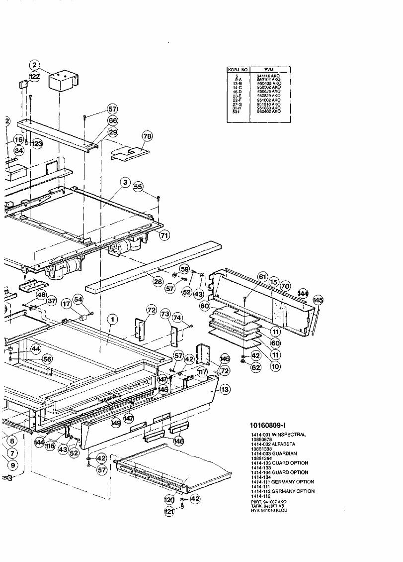
KOFU. NO.
59-A
13-B14-C16-D20-E22-F27-G31-H531
PVM
941116AKO950104 AKO950405 AKO950502 AKO950626 AKO950829 AKO951002 AKO951010AKO951030 AKO960402 AKO
1414-001 WINSPECTRAL108606781414-002 ALFABETA108613831414-003 GUARDIAN108613841414-103 GUARD OPTION1414-1031414-104 GUARD OPTION1414-1041414-111 GERMANY OPTION1414-1111414-112 GERMANY OPTION1414-112PIIRT. 941007 AKOTARK. 941007 VSHYV. 941010 KLOU


Fig. 1414 -35 Body Assembly 1086080496- 10- 10
FOR PART NUMBER 10860804 BODY ASSEMBLY 1414 10160805 960509
ITEM.NO QTY ORDER NO NAME TYPE MANUF. INF LINE
12345
678910
1112131415
1617181920
2122232425
2627282930
3132333435
3637383940
4142434445
4647484950
5154565758
596061TRWll-19
W2 0, W21,W23W27W30
W2
127811
11111
14421
11442
44141422
204842
21944
84111
14443
11111
124444
21112
24111
3111
1131003711310038113100401055560110555430
1025491810160788103549211035492210354923
1035492410454925104549281035493110454932
1035493510354940104549411127502410454943
1046078511250010112500181125201211252002
1126001011274004112740121127401311274016
1127403111274136.112780111127802610455004
1125000411274076108549871085550610355320
1035511311251018112500151127412611271016
1085511510855188108551871169004511690040
1127401511250001112710251127800210455327
1045593811274030114800471148004811480052
1148004911480050104620591165005310858057
10855441108532501086134710856412
CLAMPCLAMPCLAMPLABEL SETLABEL SET
BODYBOTTOM PLATE ASS.COVER PLATE RIGHTCOVER PLATE LEFTBOX
LIDGUIDE ASSEMBLYTUBE ASSEMBLYSUPPORTBOX ASSEMBLY
SUPPORT RIGHTSUPPORT LEFTADJUSTER NUTSCREWBRACKET ASSEMBLY
LEGWASHERWASHERRIVETRIVET
RIVETED NUTSCREWSCREWSCREWSCREW
SCREWSCREWNUTNUTBUSHING
WASHERSCREWINSULATION SETP.C.ASSEMBLYSUPPORT
LEADPINWASHERSCREWSCREW
POWER UNITPOWER-RACKVME-RACKFANFINGER GUARD
SCREWWASHERSCREWNUTBUSHING
BRACKETSCREWFERRITE CLAMPFERRITE CLAMPFERRITE CLAMP
FERRITE CLAMPCLAMPINSULATORTRANSFORMER1410 FRAME WIREING
FLAT CABLEFLATCABLEWIRING ASSWIRING ASS
AL-PLATE S=2,5AL-PLATE S=2,5AL-PLATE S=l,5
FE-PLATE S=l,5
6K14M8*60 RST.
BRASS ROUND SECTION5.3/10*1 FE YELLOWPASS
FCC-A-C8ACC3 8-AACC62-AFC31CA24
NTL51414NTL5NTL5NTL5
NTL5NTL5,1470, 1460NTL5,1470, 1460NTL5NTL5
NTL5NTL5NTL5,147 0
NTL5
1414
5.3/15*1.6 FE YELLOWPASS.3.2*7.4 MONELL3.2*8.9 MONELL
M 5 2.0-3.0 MSM 4*6 FE YELLOWPASS.M 5*10 FE YELLOWPASS.M 5*12 FE YELLOWPASS.M 5*2 0 FE YELLOWPASS.
M 5*12 FE YELLOWPASS.M8*40 YELLOWPASS.M 8 FE YELLOWPASS.M5 NYLOCPOM BLACK D=16
A6,4 ZNM6*16 FE YELLOWPASS.11 CODES = 13 PARTSIONIZER
LEAD 99.9%3*20 ST
TLP/D/BS 429TLP/D/BS435
338592RIV-TI
NTL5
NTL5RRINTL5
NTL-5
8.4/17*1.6 FE YELLOWPASS.M8*3 5 FE YELLOWPASS.M 3*4 FE YELLOWPASS.
24VDC 5W 2800RPM105X105MM
M 5*16 FE YELLOWPASS.A3, 2M 3*16 FE YELLOWPASS.M3 FE YELLOWPASS.POM-ROD D3 0 BLACK
FE-PLATE S=lM 4*8 FE YELLOWPASS.D 6, 6 MMD 13 MM40-WIRE FLAT CABLE
2 6-WIRE FLAT CABLEFOR 2 6-W.FLAT C. CLAPMTEFLON PLATE T=l27V/4,5KV 0,45VACA 23-30, SYT.
26S-2*26S40S-2X34S
10255116
43149.601-43
NTL5
NTL-5
28B2025-OAO28B2024-OAO28B2001-000
28B2022-000M-CLIP
FC3110453252CA2 08CA51
330340350380390
2930405060
7 08090
100110
12013 0140150160
170180190200210
220230240250260
270280290300165
1752852821171
172211181281229
222324360370
251176228289166
161286410420400
40543017331035
19201526
107

PART HISTORY FROM: 91-09-25 TO: 96-10-10
FOR PART
ITEM.NO
NUMBER
QTY
10860804
ORDER NO
BODY ASSEMBLY
NAME
1414
TYPE
10160805
MANUF. INF
960509
LINE DATE
Wll-19,5955
W27 11 11 1
10861450 1414 FRAME WIREING11252007 RIVET11240174 RF GASKET SPRING
3.2*6.1 MONELLBeCu 2 8MM*6MM
35 960126TLP/D/BS424 195 95112897-438-02 320 951128
108

Fig. 1414 -35 Body Assembly 10160805
109

i-ig. i
FOR PART
ITEM.NO
12346
7891011
1213141516
1718192021
2224252627
2829303132
3334353638
394044454647
1414-;
NUMBER
QTY
11112
21122
22111
16211
112
121
212
164
41216
241144
5b lop
10860806
ORDER NO
1139102610360767103607631026075410455474
1025547510355476103554771045500010455478
1045547910455480102554811025455310355488
1035548910455490104554911045549210460827
1036074210861714112500081125001011251015
1127400511274012112740881127413311274134
1127800210455763112760151045609411250041
112900131045618110459978104599791127403111250006
> uover ASS
TOP COVER ASS.
NAME
GAS SPRINGPLATE RIGHT A S S .PLATE LEFT A S S .SUPPORT PLATE ASS .PLATE
SUPPORTHINGE BODY RIGHTHINGE BODY LEFTSPRINGGUIDE
PINBRACKETTOP COVERCOVERHINGE RIGHT
HINGE LEFTNUTP I NSUPPORTPLATE
HANDLEINSULATION SETWASHERWASHERP I N
SCREWSCREWSCREWSCREWSCREW
NUTCOVER ASSEMBLYSCREWEDGE STRIPWASHER
FOOTWASHEREXTENSION ARMMOUNTING PINSCREWWASHER
temoiy
1414
TYPE
FE S = 3
AL 10X25FE-PLATE S = l , 5FE-PLATE S = l , 5D2D6H8
POM BLACK D=12
S = 5FE-PLATE S = l , 5
FE-PLrw a = l , 5MS D18d 2 , 5AL 8,2X8,2POM BLACK (10455493)
FE PLATE S=1.07 CODES = 9 PARTS4 . 3 / 9 * 0 . 8 FE YELLOWPASS5 . 3 / 1 0 * 1 FE YELLOWPASS.2*10 ST
M 4*8 FE YELLOWPASS.M 5*10 FE YELLOWPASS.M3*20 FE YELLOWPASS.M4*6 FE BLACKPASS.M5*10 FE BLACKPASS.
M3 FE YELLOWPASS.
C 2 . 9 * 6 . 5 FE YELLOWPASSFE-PLATE T=l4 . 3 / 9 * 0 . 8 FE BLACK
D12*3 RUBBERFE-PLATE T=2MS D=8MS-ROD D10M 5*12 FE YELLOWPASS.3 . 2 / 7 * 0 . 5 FE YELLOWPASS
10260807
MANUF. INF
108608069 6 - 1 0 - 1 0
960321
LINE
16-1-168-135-60 245141414141414NTL-5
NTL-5NTL-5NTL-5NTL-5NTL-5
NTL-5NTL-5NTL-5NTL-5NTL-5
NTL-5NTL-5NTL-5NTL-51414
14141400
NTL5
NTL-5
3M SJ 5012LSC-514091409
30405070
8090
100110120
1301401 5 0160170
180190200210220
23020
250260270
280290300310320
330231340241360
370242
1015
295365
PART HISTORY FROM: 91-09-25 TO: 96-10-10
FOR
ITEM
PART
.NO
NUMBER
QTY
10860806
ORDER NO
TOP COVER ASS.
NAME
1414
TYPE
10260807
MANUF. INF
960321
LINE DATE
246
10855453 INSULATION SET10460760 PLATE
7FE
CODESPLATE
= 9S=3
PARTS. 0
NTL-51414
2070
960307960320
110

KORJ. NO6
25-A27-B28-C32-D38-E52-F55-G
PVM941216AKO950922 AKO951010 AKO951020 AKO951026 AKO951121 AKO960402 AKO960508 AKO
10160805-G10860804
PIIRT. 940919 AKOTARK. 940919 VSHYV. 941010 KLOU


Fig. 1414 -36 Top Cover Assembly 10260807
KORJ. NO
29-A
PVM
951025 AKO
10260807-A10860806
PIIRT. 940921 AKOTARK. 940921 VSHYV. S9/O/Q KLOc/
111

Fig. 1414 -37 Keybank Assembly 1086086296-10- 10
FOR PART NUMBER
ITEM.NO
123
45678
91010160809-12110160809-42
PART HISTORY
QTY
11111
12221
210
88
FOR PART NUMBER
ITEM.NO QTY
10860862
ORDER NO
1156002910961123101607961026079010360786
1036078710460794104607951131005711450008
11290033112710931127400411250008
10860862
ORDER NO
KEYBANK ASS.
NAME
MOUSE MAT1414 KEYBANK ASS.KEYBOARD BOX ASS.COVER ASSEMBLYFASTENING PLATE 1
FASTENING PLATE 2LATHFASTENING LATHSLIDEINLET INSULATOR
FOOTSCREWSCREWWASHER
KEYBANK ASS.
NAME
1414
TYPE
194*244
FE PLATE S = 1 . 5
FE PLATE S = 1 . 5FE PLATE S = 3 . 0FE PLATE S = 3 . 0FOR BOX, WHITE27*21*14.5*8*1
D12*3 GREYM4*6 FE YELLOWPASS.M 4*6 FE YELLOWPASS.4 . 3 / 9 * 0 . 8 FE YELLOWPASS.
1414
TYPE
10260855
MANUF. INF
141414141414
141414141414BS 220M 45070-30017
3M SJ 5012
FROM: 95-01-10
10260855
MANUF. INF
960205
LINE
120130
102030
4050607080
90100110115
TO: 96-10-10
960205
LINE
11310057 SLIDE FOR BOX, WHITE BS 220M 450 70 950907
112

Fig. 1414 -37 Keybank Assembly 10260855PV
MK
QR
J.
NO
.
941103
AK
O950103
AK
D
<U3
113


8 Index


8 Index
IndexI
Va0
See Sample quality
AAccuracy enhancement 1-9ACSS+ 1-4Activity 3-1
Error 3-1Alpha/beta separation 1-10Automatic continuous spectrum stabilization
See ACSS+
BBackground
Calculation 3-4Correction 1-7Counting time 1-8Reduction 1-10Sample positions 1-8
Backup 5-4Barcode
See Poslden ID readerBench top model 1-6Bi-directional conveyor 1-2
cCables 6-5
Printer to PC 5-4Types 5-3
Calculation methods 3-1Chemiluminescence
Calculation 3-4ChemiStrip 1-12Problem of chemiluminescence 1-12Random coincidences 1-12Single photon event 1-12Solution to chemiluminescence 1-12
ChemiStrip 1-12Chi-square for repeat/replicates 3-5Cleaning 6-5Coincidence resolution time 6-1Colour index 3-3
Error 3-3Colour quench index 3-2Connections 6-1Count rate 3-1
Error 3-1
CounterweightSee Elevator
Counting efficiency 3-3Counting time
See BackgroundCPM
Counting 1-7Monitor 1-7
DDead time correction 6-2Decay
See Radioactive decayDetector stabilization
ACSS+ 1-4Digital Overlay Technique
See DOT DPMDimensions 6-1Disk drives
Internal 1-6Program disk drive 1-6
DOT DPM 1-8
EEfficiency 6-2Electronics 1-6Elevator 1-4Endpoint of spectrum
See External standardEnhancement - accuracy 1-9Error in
Activity 3-1Colour index 3-3Count rate 3-1Spectrum quench index 3-4Total quench index 3-3
Eu-152See External standard
EuropiumSee External standard
External standard 1-5
FFine tuning
Lock 1-14FIP
See Fractile Integral PresenFloor Stand 1-6Plnnr stanHina mnHpi 1 -f\
Fractile Integral presentation 3-2
8-1

8 Index
Frequency distributionSee Statistical analysis
GGuard detector
HHalf-life
Correction 1-12Half-life correction 3-4Hardware 6-2Humidity 6-1
IID clip
See Poslden ID readerID labels
See Poslden ID readerInitial time
See Radioactive decayInstallation instructions 5-1Ionizer 1-4
See Static electricity
Lead shielding installation 5-1Locking fine tuning 1-14
MMapping - response 6-5MCA - dual programmable 1-6MCA calibration
See Response mappingMicroprocessor 6-2Monitor
See CPM monitorSee Sample count rate variationSee Sample quality
PPAC 1-11PC
Connection to counter 5-3Plastic vial effect 1-9Port serial parameters 5-5Poslden ID reader 1-3, 6-1Printer 5-3PSA 1-10Pulse amplitude comparator 1-11Pulse shape analysis 1-10
QQuality
See Sample qualityQuench index 3-2
RRacks 6-1
Sizes 1-3Radioactive decay
Half-life correction 1-12Problem of decay 1-12
RAM 6-2RATIO 1-11Reference samples
Positions 1-8Reference spectra 3-2Repeat counting statistics 3-4Replicate counting statistics 3-4Response mapping 6-5ROM 6-2Routine maintenance 6-5
sSafety 6-3Sample count rate variation
Problem of 1-13Sample quality
See MonitorSerial port parameters 5-5Shielding 6-1
Multi-section passive shielding 1-5Shielding installation 5-1Specifications 6-1Spectrum
Library use in DPM counting 1-8Spectrum analysis program 1-14Spectrum quench index 3-3
Error 3-4Spectrum stripping
See Background correctionSQP(E)
See Total quench indexSQP(I)
See Spectrum quench indexSQP(I) DOT 1-9Stability 6-2Static electricity 1-4
Ionizer 1-13Problem of static 1-13
Statistical analysisHow to do it 1-14
8-2
8 Index
Statistics monitorSee Sample count rate variation
Surface function 3-3
TTemperature
Control 1-5, 6-1Environmental 6-1
Total quench index 3-3Error 3-3
Trend plotsSee Statistical analysis
VVolume dependence
See DPM counting
8-2