Embed Size (px)
Citation preview

Read and understand all instructions and warnings prior to installation of product and operation of vehicle.Zone Offroad Products recommends this system be installed by a professional technician. In addition to these instructions, profes-sional knowledge of disassembly/ reassembly procedures and post installation checks must be known. Minimum tool requirements include the following: Assorted metric and standard wrenches, hammer, hydraulic floor jack and a set of jack stands. See the "Special Tools Required" section for additional tools needed to complete this installation properly and safely.
»Product Safety WarningCertain Zone Suspension Products are intended to improve off-road performance. Modifying your vehicle for off-road use may result in the vehicle handling differently than a factory equipped vehicle. Extreme care must be used to prevent loss of control or vehicle rollover. Failure to drive your modified vehicle safely may result in serious injury or death. Zone Offroad Products does not recom-mend the combined use of suspension lifts, body lifts, or other lifting devices.
You should never operate your modified vehicle under the influence of alcohol or drugs. Always drive your modified vehicle at reduced speeds to ensure your ability to control your vehicle under all driving conditions. Always wear your seat belt.
»Technical SupportLive Chat provides instant communication with Zone tech support. Anyone can access live chat through a link on www.zoneoffroad.com .
www.zoneoffroad.com may have additional information about this product including the lat-est instructions, videos, photos, etc.
Send an e-mail to [email protected] detailing your issue for a quick response.
888.998.ZONE Call to speak directly with Zone tech support.
»Pre-Installation Notes1. Special literature required: OE Service Manual for model/year of vehicle. Refer to
manual for proper disassembly/reassembly procedures of OE and related components.
2. Adhere to recommendations when replacement fasteners, retainers and keepers are called out in the OE manual.
3. Larger rim and tire combinations may increase leverage on suspension, steering, and related components. When selecting combinations larger than OE, consider the additional stress you could be inducing on the OE and related components.
4. Post suspension system vehicles may experience drive line vibrations. Angles may require tuning, slider on shaft may require replacement, shafts may need to be lengthened or trued, and U-joints may need to be replaced.
5. Secure and properly block vehicle prior to installation of Zone Offroad Products. Always wear safety glasses when using power tools.
6. If installation is to be performed without a hoist, Zone Offroad Products recommends rear alterations first.
7. Due to payload options and initial ride height variances, the amount of lift is a base figure. Final ride height dimensions may vary in accordance to original vehicle attitude. Always measure the attitude prior to beginning installation.
Difficulty Leveleasy 1 2 3 4 5 difficult
Estimated installation: 6-8 hours
Special Tools RequiredCutoff Tools, Optional Welding, 36mm socket, T30 Torx bit, general hand tools
Tire/Wheel Fitment305/55/20 w/ 5-1/4" Backspacing
295/70/17 or 18 w/ 4-1/2" Back-spacing
»Zone Offroad Products • 491 W. Garfield Ave., Coldwater, MI 49036 • 888.998.ZONE • www.zoneoffroad.com
rev072616
#C2552 2015 Chevy Colorado/GMC Canyon5.5" Lift System

pg. 2 - Installation -
*Important* Verify you have all of the kit components before beginning installation.
C2552 Kit Contents
ZONC2550 1 Steering Knuckle - DRV 1 Tie Rod End 1 9/16" SAE washer 1 Steering Stop ZONC2551 1 Steering Knuckle - PASS 1 Tie Rod End 1 9/16" SAE washer 1 Steering Stop ZONC2552 1 Front Crossmember 1 Rear Crossmember 1 DRV Diff Drop 1 Pass Diff Drop 1 Bolt Pack - Main Crossmember 1 Bolt Pack - Diff Drop Hardware ZONC2553 1 Diff Skid Plate 1 Bolt Pack - Skid Plate / Bump Stop / Misc. 1 Bump Stop - DRV
1 Bump Stop - PASS 2 3/8" Serrated Edge Flanged Nut 2 Urethane Bump Stop 2 Sway Bar Link Stem 8 Sway Bar Link Bushing 1 Bolt Pack - Sway Bar Links 3 1/2" Rivet Nut 1 Bolt Pack - Rivet Nut Installation 1 Front Drive Shaft Spacer 1 Bolt Pack - Drive Shaft Spacer 3 9/16" USS Washer 4 Zip Tie 1 Loc-tite bottle ZONC2554 2 5.5" Strut Spacer 1 Bolt Pack - Strut Spacers ZONC2409 2 4" Rear Block 4 9/16" x 2-9/16" x 11-3/8" U-Bolt 8 9/16" SAE Washer 8 9/16" High Nut 5 Zip Ties
STRUT SPACER
REAR BLOCK
DRV BUMP STOP
PASS BUMP STOP
STRUT SPACER
SWAY BARLINK
SWAY BARLINK
DIFF SKID PLATE
CV SPACER
REAR CROSS-MEMBER
FRONT CROSS-MEMBER
PASS DIFF DROP
DRV DIFF DROP
ZONE COLORADO PARTS

Installation - pg. 3
Installation Instructions1. Park vehicle on clean, flat, and level surface. Block the rear wheels for safety.
2. Raise the front of the vehicle and support the frame rails with jackstands.
3. If a plasma cutter is to be used for frame bracket modification (later in installation), it is recommended to disconnect the battery at this time.
»Disassembly instructions
4. Remove the front wheels
5. Remove the clip from the brake line to allow the brake line to detach from the bolt on brake line bracket.
6. Remove the brake bracket from the side of the upper strut mount, discard flanged bolt and bracket. (Fig 1).
Figure 1
7. Disconnect the brake caliper from the steering knuckle, retain mounting bolts. Hang the caliper out of the way; do NOT allow the caliper to hang from the brake line. (Fig 2)
Figure 2
Important—measure before starting!Measure from the center of the wheel up to the bottom edge of the wheel opening
LF__________ RF__________
LR__________ RR__________
» Note:These trucks are extremely sensi-tive to out of balance or tires with large lugs. A set of well balanced all terrain tires is recommended to keep the steering wheel from hav-ing a shimmy when driving.

pg. 4 - Installation -
8. Remove the torx head bolt (T30) that attaches the rotor to the hub. Keep bolt for reinstallation. (Fig 3)
Figure 3
9. Disconnect the ABS wire from the backside of the steering knuckle, remove the clip and retain the bolt. (Fig 4)
Figure 4
10. Remove the ABS sensor from the side of the knuckle (T30), retain mounting bolt. (Fig 5)

Installation - pg. 5
Figure 5
11. Remove the CV nut, CV’s have a tight fit to the hubs, it may be necessary to use an air hammer to separate them. Reinstall the nut a few turns to keep from damaging the CV shaft if this method is used. (Fig 6)
Figure 6
12. Remove the factory sway bar links, they will not be reused. (Fig 7)
Figure 7

pg. 6 - Installation -
13. Break the jam nuts loose on the tie rod ends at this time. The factory tie rod ends will be replaced later in the installation. (Fig 8)
Figure 8
14. Remove the ball joint nuts and tie rod end nuts. Use an appropriate tool to unseat the tapers from the factory knuckle. It is NOT recommended to use a hammer to separate the joints. (Fig 9)
Figure 9
15. Remove the knuckle and hub assembly from the vehicle.
16. Remove the factory struts. Remove the lower bolt that attaches to the control arm and the 3 nuts that attach the strut to the upper strut mount. Do NOT remove the center nut that holds the strut assembly together. (Fig 11)

Installation - pg. 7
Figure 11
17. Remove the lower control arms. Retain the cam bolts / washers. (Fig 12, 13)
Figure 12
Figure 13

pg. 8 - Installation -
»Differential removal
18. Disconnect the differential breather hose from the differential and the central axle disconnect wiring harness (Fig 14, 15)
Figure 14
Figure 15
19. Disconnect the front drive shaft from the differential. Discard front mounting hardware, it will not be reused) (Fig 16). Disconnect the front driveshaft from the transfer case, SAVE hardware, it will be reused. Remove the front driveshaft from the vehicle.
Figure 15 NoteThe differential breather is difficult to access. It is easier to disconnect when the differential is lowered slightly..

Installation - pg. 9
Figure 16
20. Remove the rear differential mounting bolt (Fig 17). Remove the rear factory cross member (Fig 18), Discard hardware, it will not be reused.
Figure 17
Figure 18

pg. 10 - Installation -
21. Support the differential with a hydraulic jack (transmission jack preferred). Re-move the remaining two front mounting bolts and lower the differential from the vehicle. (Fig 19)
Figure 19
»frame moDification
22. The front factory lower control arm pocket will need to be modified to allow the new crossmember to be installed.
Front Pocket Modification23. Measure down 1-1/8” from the BOTTOM of the factory slot on both the front and
back sides and make a horizontal mark. Connect these two lines by measuring ‘in’ towards the center of the vehicle 1-1/8” and making a line that goes from front to back. Remove this section of material from the vehicle. Use a grinder to make the faces flush and remove any sharp edges so that the cross member can be installed easily. Coat with paint. (Fig 20a, 20b)

Installation - pg. 11
Figure 20a
Figure 20b

pg. 12 - Installation -
Passenger’s Rear Pocket Modification24. Draw a line that connects the top of the outside slot and bottom of the inside slot
and remove the material from vehicle. Use a grinder to remove sharp edges, coat with paint when completed. (Fig 21a, 21b)
REMOVE THIS SECTIONPASSENGER'S SIDE FRONTOF THE POCKET
CUT LINE WITH TOP OF SLOT
Figure 21a
Figure 21b

Installation - pg. 13
Driver’s Rear Pocket Modification25. Draw a horizontal line from the top of the outside slot.
26. Draw a vertical line from the center of the outside slot
27. Draw a line that would go through the center of the stock alignment pin that is perpendicular (about 45 degrees from horizontal) to the inside face.
28. Remove this section of material from the vehicle, remove any sharp edge with a grinder, and coat with paint. (Fig 22a, 22b)
.500" ABOVETHE ALIGNMENTPINT
CUT TANGENTWITH TOP OF SLOT
CUT JUST TO THE INSIDE OF THESTOCK ALIGNMENT PIN /ON CENTER OF LOWER SLOT
REMOVE THIS SECTIONOF MATERIAL DRIVER'S
SIDE ONLY
Figure 22a
Figure 22b

pg. 14 - Installation -
»crossmember / Differential installation
29. Install the new front crossmember with new 5/8” hardware. Run the bolts from front to rear, Do NOT put the nuts on the bolts at this time. Crossmember are a tight fit if not enough material was removed during the frame pocket modification. (Fig 23)
Figure 23
30. Install the new differential drop brackets with new 14mm hardware to the frame. Brackets will attach to the front cross member hardware, attach with 5/8” nuts and washers. Leave all hardware loose. (Fig 24)
Figure 24
31. Install differential to the new drop brackets with 9/16” hardware. (Fig 25)
Step # 29 Note:5/8" x 4-1/2" Crossmember Hard-ware is in Bolt Pack # 680
Step # 30 Note:Differential hardware is in Bolt Pack # 681. Use 14mm x 30mm to attach the bracket to the frame.

Installation - pg. 15
Figure 25
32. Raise the rear differential mount. Install rear cross member with new 5/8” hard-ware. Attach differential to rear crossmember with new 9/16” hardware. (Fig 26)
Figure 26
33. Clearance the exhaust connection flange joint to create clearance for the front drive shaft. Grind the material away until the edge is flush with the edge of the flanged nut. (Fig 27)
Step # 31 Note:Differential hardware is in Bolt Pack # 681. Use 9/16" x 3-1/2" Hardware..
Step # 32 Note:After test driving, if a vibration is present in the front driveshaft, use the provided 9/16” USS washers to space up the rear mount between the differential mount and the rear cross member. Gas model recommended to not use any spacer washers, Diesel model recommended to use two 9/16” spacer washers. Driving the vehicle and adding and removing spacer washers is the best way to reduce diveline vibrations.

pg. 16 - Installation -
Figure 27
34. Attach the front driveshaft to the differential with the driveshaft spacer and new 10mm hardware with loc-tite. Tighten to 40 ft-lbs. (Fig 28)
Figure 28
Step # 34 Note:Driveshaft hardware is in Bolt Pack # 828. Use 10mm x 75mm Hard-ware..Use loc-tite

Installation - pg. 17
»bump stop installation
35. Remove the factory bump stops (Fig 29)
Figure 29
36. Clearance the hole inside the bump stop cup to 11/16”. Insert and seat ½” rivet nut. Follow rivet nut installation at the end of the instruction sheet. (Fig 30)
Figure 30
37. Attach the new bump stop extension to the rivet nut and rear crossmember with ½” hardware. Attach the bump stops to the bracket with 3/8” serrated edge flanged nut. (Fig 31a, 31b)

pg. 18 - Installation -
Figure 31a
Figure 31b
38. Install lower control arms with factory cam bolts and nuts. Snug, but do not tighten at this time.
39. Go back and tighten 5/8” differential hardware to 120 ft-lbs., 9/16” and 14mm dif-ferential hardware to 90 ft-lbs. Tighten ½” bump stop hardware to 65 ft-lbs.
Step # 37 Note:Bump Stop hardware is located in #684. Use 1/2" x 2" into the rivet nut, 1/2" x 1-1/4" to the rear cross-member, and 3/8" serrated edge flanged nut - included with the bump stop bag kit B1137 to secure the bumpstop to the bracket

Installation - pg. 19
»strut moDification
40. Locate the upper strut spacers. Attach the strut spacers to the stock struts with fac-tory hardware. Tighten to 40 ft-lbs. (Fig 32)
Figure 32
41. Install the strut and spacer into the vehicle. Attach the strut to the upper mount with new 3/8” nylock nuts and washers. Attach lower mount to the lower control arm with factory bolts. Tighten the 3/8” hardware to 35 ft-lbs; do NOT tighten the lower mount at this time. It will be done at the end of the installation with the vehicle weight on the ground. (Fig 33)
Figure 33
»KnucKle assembly
42. Remove the factory hub and dust shield from the stock knuckles. Transfer them over to the new steering knuckle. Note: You MUST install the dust shield, failure to do so will cause ABS problems. (Fig 34)
Step # 40 Note:Use stock hardware. Tighten to 40 ft-lbs.
Step # 41 Note:Strut Hardware is located in Bolt Pack #943. Use the 3/8" nuts with washers to attach the strut to the frame. Use the factory lower hard-ware at lower mount.
pg. 20 - Installation -
Figure 34
43. Apply loc-tite to the factory hub bolts, and tighten hub hardware to 95 ft-lbs.
44. Install grease zerk into new tie rod ends. Install the new tie rod ends onto the fac-tory inner tie rods. Grease the tie rod ends before driving the vehicle. (Fig 35)
Figure 35
45. Install new steering knuckle assembly to the lower control arm and run the CV shaft through the hub. Attach upper ball joint and new tie rod end to knuckle assembly, use the included washer under the nut for the tie rod end. Use stock hardware tighten lower ball joint to 92 ft-lbs, upper ball joint to 70 ft-lbs, tie rod end to 44 ft-lbs, and CV nut to 177 ft-lbs. (Fig 36)

Installation - pg. 21
Figure 36
46. Reinstall the brake rotors with the torx bit holding the rotor to the hub assembly.
47. Reinstall the brake calipers with factory hardware. Tighten to 148 ft-lbs.
48. Clean any debris from the ABS sensors. Install the ABS sensors into the steering knuckle with factory hardware. Tighten to 11 ft-lbs. (Fig 37a)
Figure 37a
49. Attach the ABS sensor wire to the back of the steering knuckle with a new cable clamp and factory hardware. The grommet on the ABS wire can be slid by spray-ing it with silicone spray. Ensure there is adequate slack through wheel travel and full steering range of motion. (Fig 37b)
Step # 48 Note:Any metallic debris on the ABS sensor can cause ABS errors, make sure the ABS sensor is clean before installing into the new steering knuckle.

pg. 22 - Installation -
Figure 37b
50. Install new sway bar links with washers and bushings as shown. Attach with 7/16” nylock nuts. Tighten until the bushings begin to swell – do NOT over tighten. Fig 38
Figure 38
Step # 50 Note:Sway bar hardware is in B1136 Bag Kit. Use the 7/16" nuts with washers located in Bolt Pack #682

Installation - pg. 23
»braKe line moDification
51. Carefully form the brake line to allow the mounting end to attach to the side of the bump stop cup. Reinstall the factory retaining clip to hold the brake line in place.
52. Reform the hard line slightly to create clearance from any sharp edges. Attach brake line to the side of the frame rail and the factory bump stop bracket by drilling 7/32” holes and using 3/16” cable clamps with ¼” self threading bolts. Fig 39
Figure 39
53. Recheck differential hardware for proper torque. Install skid plate with 3/8” hard-ware. Fig 40
Figure 40
Step # 52 Note:Brakeline clips and hardware are in bolt pack # 684.
Step # 53 Note:Differential skid plate hardware is in Bolt Pack # 684

pg. 24 - Installation -
»Final Front Steps54. Reinstall wheels. Tighten to factory specifications.
55. Lower vehicle to the ground. Adjust Cams as shown Fig 42a - front, Fig 42b - rear, Tighten Cam hardware to 170 ft-lbs. Tighten lower strut hardware to 95 ft-lbs.
Figure 42a
Figure 42b
Rear Installation56. Block the front wheels for safety. Raise the rear of the vehicle and support frame
rails with jackstands.
57. Remove the stock wheels and tires.
58. Disconnect the ABS wire from the clip on the side of the frame rail, this will al-low extra slack in the ABS line. Figure 43
CAM PlacementThis is not the final alignment, but a good start for driving to an alignment shop. Adjust the toe-in to approximately 1/8” in, and straighten the steering wheel. Do NOT drive the vehicle with the steering wheel off-center.42A - FRONT CROSSMEMBER SHOWN42B - REAR CROSSMEMBER SHOWN

Installation - pg. 25
Figure 43
59. Remove the e-brake cable guide bracket from the side of the frame rail on the driver’s side. It will not be reinstalled.
60. Form the stock brake line upper bracket ‘down’ to gain adequate slack. Use an adjustable wrench to form the stock brake line bracket down. Figures 44a, 44b
Figure 44a
Figure 44b

pg. 26 - Installation -
61. Working on one side of the vehicle at a time. Support the axle with a hydraulic jack, remove the factory u-bolts. Remove the stock shocks, retain hardware.
62. Diesel Models Only (Step #62-66): To remove the driver side upper shock bolt the DEF tank may be needed to be slid over to provide clearance. If the bolt can-
not be removed, follow these instructions to provide clearance to the DEF tank.
Figure 45
63. Lower the spare tire and remove the spare tire from the vehicle. Follow the factory manual for removal of the spare tire. Remove the heat shield protecting the spare tire from the exhaust. There are 3 plastic push pins supporting the heat shield.
Figure 46
64. Support the DEF tank with a jack. Remove the two bolts supporting the front of the DEF tank. Remove the bolt on the passenger side of the DEF tank

Installation - pg. 27
Figure 47
Figure 48
65. Remove the two nuts on the back side of the DEF tank. The support brackets on the back side of the DEF may also need to be loosened in order to slide the DEF tank over.

pg. 28 - Installation -
Figure 49
Figure 50
66. Slide the DEF tank towards the passenger side of the vehicle until there is enough clearance to remove the driver side upper shock bolt. Install the new shock with the OEM shock bolt. After the new shock in installed, reinstall the DEF tank, spare tire heat shield, and spare tire in the reverse sequence.
67. Lower the axle and install new lift block. Install new u-bolts with nuts and wash-ers. Snug but do not tighten at this time. Figures 51a, 51b

Installation - pg. 29
Figure 51a
Figure 51b
68. Repeat block installation on opposite side of vehicle.
69. Grease and install new bushings and sleeves into shocks. Install the shocks with factory hardware. Install the shocks with the body down towards the axle. Tighten to 55 ft-lbs.
Step # 69 Note:Install new shocks with the body down at the axle with factory hardware.

pg. 30 - Installation -
70. Lower the axle and check for adequate slack in the brake lines and abs wire, adjust as necessary.
71. Slide the grommet on the ABS wire on the passenger’s side by the exhaust up (use silicone spray to allow the grommet to slide easily). Slide the ABS wire heat shield tubing up and secure with a zip tie. Figure 52a
72. Attach the ABS wire to the u-bolt with included zip tie Figure 52b, repeat on opposite side.
Figure 52a
Figure 52b

Installation - pg. 31
73. Use two zip ties, secure the e-brake cables together in front of where the old e-brake cable guide bracket contacted the cables. Figure 53
Figure 53
74. Install wheels, tighten lug nuts to factory specifications.
75. Lower the vehicle to the ground and torque u-bolts to 110 ft-lbs.
76. Reconnect the battery.
77. Recheck all hardware for proper torque. Check again after 500 miles.
78. A front end alignment is now required. Ensure the lower cam bolts are torqued to 170 ft-lbs after alignment.
»Optional Weld On Steering Stops:79. Included are optional weld on steering stops. These can be welded to the lower
control arm to reduce rubbing or eliminate any interference issues that my be present at full steering lock. Disconnect the battery, prep lower control arm for welding, weld steering stop onto the lower control arm as shown. Coat with paint when completed. Figures 54a, 54b
Figure 54a

pg. 32 - Installation -
Figure 54b
»Optional Front Fenderwell Modification for Tire Clearance:80. Remove the 4 lower T-15 Torx head bolts that hold the fenderwell to the plastic
support piece. Figures 55a, 55b
Figure 55a

Installation - pg. 33
Figure 55b
81. Trim back to the first full support rib. Remove this section from the support piece. Figures 56a, 56b
Figure 56a
Step # 81 Note:A sawzall works well for trimming the factory plastic. A box cutter style knife with the blade heated by a MAP gas / propane torch cuts the factory plastic bumper cover nicely and leaves a good smooth finish.

pg. 34 - Installation -
Figure 56b
82. Remove the nut clips from the trimmed piece. Hold the inner fenderwell up to the front support piece and drill new holes for the mounting hardware at a convenient location. Attach the inner fender to the plastic support piece with factory torx bit hardware. Trim a slight amount on the plastic bumper cover for additional clearance if required. Figures 57a, 57b
Figure 57a
Installation - pg. 35
Figure 57b
Rivet Nut Installation Instructions
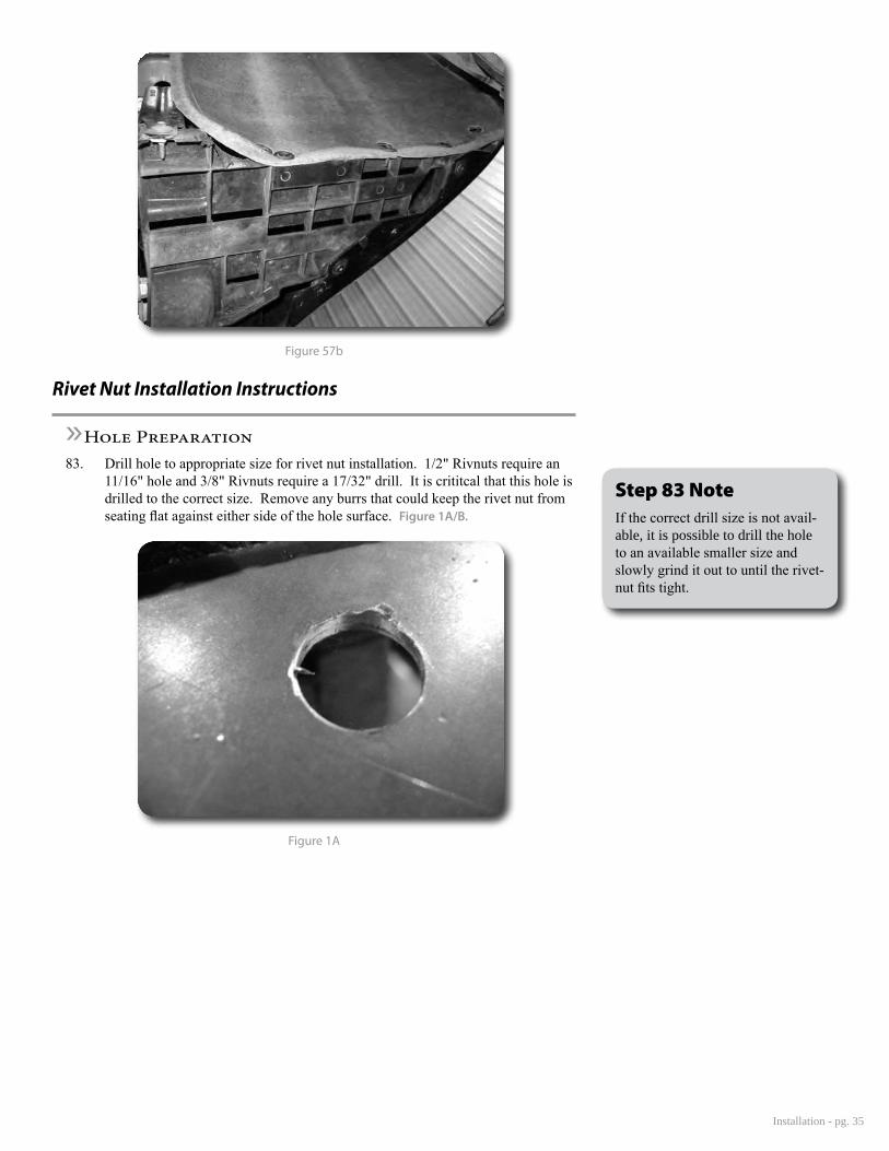
»Hole Preparation83. Drill hole to appropriate size for rivet nut installation. 1/2" Rivnuts require an
11/16" hole and 3/8" Rivnuts require a 17/32" drill. It is crititcal that this hole is drilled to the correct size. Remove any burrs that could keep the rivet nut from seating flat against either side of the hole surface. Figure 1A/B.
Figure 1A
Step 83 NoteIf the correct drill size is not avail-able, it is possible to drill the hole to an available smaller size and slowly grind it out to until the rivet-nut fits tight.

pg. 36 - Installation -
Figure 1B
»Rivet Nut Installation Tool Assembly84. For a 3/8" rivet nut, place the provided 3/8" SAE flat washer on the 3/8" x 1-1/2"
bolt, followed by 7/16" hex nut and then a 3/8" serrated washer. Figure 2 Thread this tool assembly into the rivet nut.
Figure 2
85. For a 1/2" rivet nut, place the provided 1/2" SAE washer on a 1/2" x 2” bolt fol-lowed by a 9/16” high nut and 1/2" serrated edge lock washer. Thread this tool assembly into the rivet nut as shown. Figure 3.

Installation - pg. 37
Figure 3 - 1/2" Rivet Nut Shown
»Rivet Nut Installation86. Verify the correct size rivet nut for the application based on the thickness of
material where the rivet nut is to be installed using the following chart.
Part Number
ThreadSize
Body Length (in)
Material Thickness(in)
Drill Size (in)
Min. Max.95105A159 3/8-16 .690 .027 .150 17/3295105A168 3/8-16 .805 .150 .312 17/3295105A169 1/2-13 1.150 .063 .200 11/1695105A170 1/2-13 1.300 .200 .350 11/16
87. Place the installation tool with the rivet nut threaded on the end into the appro-priately sized hole.
88. For a 3/8" rivet nut, hold the nut closest to the rivet nut still with an 5/8" wrench and tighten the 3/8" bolt with a 9/16 wrench to set the rivet nut. Be sure to hold the rivet nut flush to the surface and square to the hole as it is tightened. Figure 4
89. For a 1/2" rivet nut, hold the nut closest to the rivet nut still with an 7/8" wrench and tighten the 1/2" bolt with a 3/4" wrench to set the rivet nut. Be sure to hold the rivet nut flush to the surface and square to the hole as it is tightened. Figure 4
Step 88 & 89 NoteIf available, an impact gun is recommended for tightening the bolt to ensure the rivet nut remains sqaure to the hole and to ease hold-ing the nut from spinning.

pg. 38 - Installation -
Figure 4 - 1/2" Rivet Nut shown
»Torque Specifications90. 3/8" rivet nuts will approach 40 ft. lbs for maximum grip strength. Do not
exceed 45 ft-lbs when setting the rivet nut.
91. 1/2" rivet nuts will approach 90 ft lbs for maximum grip strength. Do not ex-ceed 100 ft-lbs when setting the rivet nut.
»Rivet Nut Tool Removal92. Once the center bolt is tightened, remain holding the nut from spinning with the
wrench and loosen the center bolt to remove the installation tool.
93. Verify proper installation by checking for consistent rivet nut deformation to see the threads are sqaure and centered to the rivet nut. Figure 5.
Figure 5
Step 90 & 91 NoteIf using the recommended inpact gun, use caution to not exceed the recommended torque specificatons.
Step 92 *IMPORTANT*It is very important to hold the nut as the bolt is loosened because the grip of the star washer will try to spin the rivet nut and ruin the installation.

Installation - pg. 39