Embed Size (px)
Citation preview

Director, Operational Test and Evaluation
Warfighter Information Network – Tactical (WIN-T) Increment 2
Second Follow-on Operational Test and Evaluation
May 2015
This report on the Warfighter Information Network – Tactical (WIN-T) fulfills the provisions of Title 10, United States Code, Section 2399. It assesses the adequacy of testing and the operational effectiveness, operational suitability, and survivability of the WIN-T.
J. Michael Gilmore Director

Report Documentation Page Form ApprovedOMB No. 0704-0188
Public reporting burden for the collection of information is estimated to average 1 hour per response, including the time for reviewing instructions, searching existing data sources, gathering andmaintaining the data needed, and completing and reviewing the collection of information. Send comments regarding this burden estimate or any other aspect of this collection of information,including suggestions for reducing this burden, to Washington Headquarters Services, Directorate for Information Operations and Reports, 1215 Jefferson Davis Highway, Suite 1204, ArlingtonVA 22202-4302. Respondents should be aware that notwithstanding any other provision of law, no person shall be subject to a penalty for failing to comply with a collection of information if itdoes not display a currently valid OMB control number.
1. REPORT DATE 08 MAY 2015
2. REPORT TYPE N/A
3. DATES COVERED
4. TITLE AND SUBTITLE Warfighter Information Network - Tactical (WIN-T) Increment 2Follow-on Operational Test and Evaluation 2 (FOT&E 2) Report
5a. CONTRACT NUMBER
5b. GRANT NUMBER
5c. PROGRAM ELEMENT NUMBER
6. AUTHOR(S) 5d. PROJECT NUMBER
5e. TASK NUMBER
5f. WORK UNIT NUMBER
7. PERFORMING ORGANIZATION NAME(S) AND ADDRESS(ES) Director, Operational Test and Evaluation (DOT&E)
8. PERFORMING ORGANIZATIONREPORT NUMBER
9. SPONSORING/MONITORING AGENCY NAME(S) AND ADDRESS(ES) 10. SPONSOR/MONITOR’S ACRONYM(S)
11. SPONSOR/MONITOR’S REPORT NUMBER(S)
12. DISTRIBUTION/AVAILABILITY STATEMENT Approved for public release, distribution unlimited.
13. SUPPLEMENTARY NOTES The original document contains color images.
14. ABSTRACT
15. SUBJECT TERMS
16. SECURITY CLASSIFICATION OF: 17. LIMITATION OF ABSTRACT
SAR
18. NUMBEROF PAGES
69
19a. NAME OFRESPONSIBLE PERSON
a. REPORT unclassified
b. ABSTRACT unclassified
c. THIS PAGE unclassified
Standard Form 298 (Rev. 8-98) Prescribed by ANSI Std Z39-18

This page intentionally left blank.

i
Executive Summary This report assesses the test adequacy, operational effectiveness, operational suitability,
and survivability of the Warfighter Information Network – Tactical (WIN-T) Increment 2 to support a Full-Rate Production decision scheduled for May 11, 2015. This report is the second follow-on assessment to the Director, Operational Test and Evaluation (DOT&E) WIN-T Increment 2 Initial Operational Test and Evaluation (IOT&E) Report dated September 2012. The IOT&E report supported the September 18, 2012, Full-Rate Production decision and the WIN-T Increment 2 Follow-On Test and Evaluation (FOT&E 1) Report dated September 2013, supported the September 19, 2013, Full-Rate Production decision.
The Defense Acquisition Executive issued an Acquisition Decision Memorandum (ADM) on September 27, 2013, which directed the Army to conduct a second FOT&E (FOT&E 2) to demonstrate: (1) the Point of Presence (PoP) meets threshold reliability requirements; (2) significant reduction in the complexity of the start-up, reboot, troubleshooting, and shutdown procedures for the Soldier Network Extension (SNE) and PoP; (3) significant reduction in the complexity of the SNE Combat Net Radio (CNR) Gateway operations. The ADM directed that FOT&E 2 assess other deficiencies noted during FOT&E 1, including the Highband Networking Waveform (HNW) network and cybersecurity.
This assessment is based on the WIN-T Increment 2 FOT&E 2 conducted October 15 through November 2, 2015, by the Army Test and Evaluation Command at Fort Bliss, Texas, and White Sands Missile Range, New Mexico. It was conducted in conjunction with the Army’s Network Integration Exercise 15.1. The test location provided a dispersed environment in desert and limited urban terrain. Testing of WIN-T Increment 2 was adequate and was conducted in accordance with the DOT&E-approved test plan. DOT&E’s evaluation focused on the issues listed in the 2013 ADM and the first demonstration of PoP and SNE configuration item integration on Stryker vehicles during an operational test.
The test unit, 2nd Brigade, 1st Armored Division, at Fort Bliss/White Sands Missile Range is a heavy brigade combat team that provided a brigade headquarters and six battalions equipped with WIN-T Increment 2. The FOT&E 2 test unit conducted mission operations, which included offensive, defensive, and stability missions with WIN-T Increment 2 employed at-the-halt and on-the-move.
The Army intends WIN-T to provide the information transport backbone to brigade and battalions. WIN-T Increment 2 builds upon the WIN-T Increment 1 at-the-halt network to support on-the-move operations through two waveforms, the Net-Centric Waveform (NCW) for ground-to-satellite communications and the HNW for ground-to-ground, line-of sight communications when the unit command centers are at-the-halt or on-the-move. The WIN-T communications backbone enables exchange of voice, video, and data throughout theater, corps, division, brigade combat team, battalion, and company level elements. The new capabilities Increment 2 provides include enhanced on-the-move Voice over Internet Protocol (VoIP) telephone and mission command applications.
ii
Operational Effectiveness
During IOT&E and FOT&E 1, all items not assessed during FOT&E 2 were found operationally effective. During FOT&E 2, the following configuration items were operationally effective:
• SNE with CNR Gateway
• NCW, reassessed due to FOT&E network outages
• PoP and SNE integrated into Stryker vehicles
The following configuration items were not operationally effective:
• HNW line-of-sight network and network management tools
• Tactical Relay – Tower (TR-T)
The SNE was operationally effective. The CNR Gateway interface was improved and Soldiers were able to bridge their dispersed unit networks with the CNR Gateway. By using the CNR Gateway, brigade and battalion commanders can obtain situational awareness from the forward areas of combat. Soldiers made great use of the WIN-T Chat application during unit operations. Mine-Resistant Ambush Protected (MRAP) All-Terrain Vehicle (MATV) SNE users found the back seat display useful and applications such as Tactical Ground Reporting System (TIGR) to be effective. During the 2013 FOT&E 1, the SNE was useful for conducting VoIP phone calls; however, long call set up times limited the utility of VOIP. During FOT&E 2, VOIP phone calls supported the unit’s mission and call set up times were improved with less than 1.5 percent of calls demonstrating 30 second or longer call setup times.
The NCW network was operationally effective. There were two NCW network outages on May 18, 2013, during FOT&E 1 (Network Integration Evaluation 13.2), that degraded the network’s satellite support for 1 hour or more due to disadvantaged users placing a drain on satellite power. Between FOT&E 1 and 2, the Army applied fixes to NCW network to support a more resilient network. During FOT&E 2, the NCW network did not demonstrate the extended outages seen during FOT&E 1.
The Stryker PoP and SNE were operationally effective and similar to the effectiveness demonstrated by the MATV PoP and SNE. Stryker SNEs exhibited a higher rate of satellite :acquire” and “align” states than MATV SNEs. This may have been due to the limited number of Stryker SNE and Stryker PoPs and the differences in mission, location, and usage.
The HNW network, TR-T, and HNW network management tools were not operationally effective. Between IOT&E and FOT&E 1, the HNW/NCW decision algorithm was modified to prefer NCW over marginal HNW links to reduce waveform cycling behavior (as described in the IOT&E report). Tactics, techniques, and procedures were also modified to encourage network operations to restrict the number of immediate HNW neighbors and to conduct more monitoring of the HNW network. Between FOT&E 1 and 2, the Army made no substantial changes to the HNW network.

iii
When evaluated in an operational environment, using the same metrics as those used in Army developmental testing, HNW with TR-T did not demonstrate the Capabilities Production Document transmission range with data rate for on-the-move and at-the-halt HNW, or the potential link quality to meet the required data rates in an operational environment.
HNW demonstrated limited transmission range for on-the-move nodes, especially in forested areas. Ranges for mobile PoP to TCNs using the HNW network were similar to FOT&E 1. HNW connects on-the-move PoPs to TCNs, at distances greater than 5 kilometers, 50 percent of the time providing intermittent links at low data rates. Based on IOT&E results measured at Fort Campbell, Kentucky, for the most part, HNW mobile transmission range is limited to distances of 1 kilometer or less in forested terrain.
HNW demonstrated low quality at-the-halt links that provided limited range for transmitting data. When supporting command posts, the HNW network for the most part supported collocated Tactical Operations Centers (TOCs) and at further distances, the NCW satellite network carried the majority of network traffic. HNW carried 63 percent of the brigade’s inter-TOC traffic, but 72 percent of this traffic was between collocated TOCs within a distance of 1 kilometer or less. As distance increased to 10 kilometers, the HNW network required the TR-T to support more user traffic. At distances of 10 kilometers or more, the NCW satellite network supported 81 percent of user traffic while the majority of remaining HNW traffic was supported by HNW using the TR-T.
In the absence of the NCW satellite, HNW did not maintain the brigade network. The availability of satellite communications cannot be guaranteed under all possible combat scenarios, particularly when conducting operations against an enemy with the capability to jam such communications or execute successful computer network attack. Also, terrain, vegetation and frequency spectrum limitations based on the unit’s location in the world can further limit satellite support. During FOT&E 1 NCW outages, HNW did not maintain the WIN-T network in the absence of NCW satellite with three to five battalion command posts separated from the brigade network.
Poor use of the TR-T and the Range Throughput Extension Kit (RTEK) antenna did not provide range extension to the HNW network. At the beginning of FOT&E 2, the TR-T was placed at an advantageous location, on a hill, providing line-of-sight. Even in the advantageous location, the TR-T provided intermittent support to keep stationary command posts, located at operational distances of 10 kilometers or more, in a single HNW network. TR-T HNW links were of low quality and unstable throughout the day, providing asymmetrical use of HNW and NCW. Although each TCN and the TR-T is equipped with a RTEK flat-paneled antenna, which improves the link quality of long-distance links, the brigade made little use of this capability.
HNW is not stable at distances. During FOT&E 2, longer distance HNW links were intermittent and the connectivity was not symmetric. In these cases, data traveling between WIN-T Increment 2 command posts would use an HNW link in one direction, while the reverse connection would use an NCW satellite link for extended periods of time. This lack of symmetry could affect the Soldier’s use of applications that are latency sensitive, such as VoIP, and increase network congestion due to queuing problems.

iv
HNW network management tools did not support the Soldiers’ employment of the HNW network. Soldiers commented that the HNW tools provided inconsistent and inaccurate results for TR-T placement. The TR-T was relocated halfway through FOT&E 2 to a location that did not provide additional connectivity. Further analysis showed significant line-of-sight terrain blockage that would interfere with HNW transmission. In this position, when brigade units moved north, the TR-T did not provide connectivity from the brigade command post to nearby maneuver battalions and other dispersed elements.
Operational Suitability
The suitability ratings for FOT&E by configuration item are shown in Table 1.
Table 1-1. WIN-T Increment 2 Operational Suitability Configuration Item Suitable Maintainable Reliable
VWP Yes Not Assessed1 Yes
M-ATV PoP Yes No Yes
Styker PoP No No Yes
M-ATV SNE Yes No Yes
Stryker SNE No Yes No 1With one 3-minute maintenance action, not able to assess VWP Mean Time To Repair (MTTR).
During FOT&E 2, the Vehicle Wireless Package (VWP), the M-ATV PoP, and M-ATV SNE were operationally suitable. The Stryker PoP and Stryker SNE were not operationally suitable. The WIN-T PoP met reliability requirements for both the M-ATV and Stryker variants. The M-ATV SNE met reliability requirements, but the Stryker SNE did not meet reliability requirements. The majority of WIN-T Increment 2 Essential Function Failures are due to software failures.
The Stryker SNE met the 30-minute maintainability requirement. Neither the M-ATV or Stryker PoP nor the M-ATV SNE met the maintainability requirement. The maintainability of the VWP could not be assessed (no failures were observed in the test). The unit success rate was similar to FOT&E 1 and the Army remains dependent upon contractor field service representatives for maintenance when deployed to combat operations.
The Stryker PoP and SNE presented Soldiers with significant human factors engineering and integration issues that interfered with the unit’s performance of mission operations. These Stryker WIN-T deficiencies include:
• Position of WIN-T PoP and SNE displays in front of gunner position
• WIN-T Increment 2 antennas prevent 360-degree gun coverage
• WIN-T Increment 2 operations with the engine turned off can drain batteries to a level that requires replacement

v
• Operating WIN-T Increment 2 on vehicle power does not allow “Silent Watch” operations.
Stryker commanders reported that WIN-T Strykers required more battery replacements than Stryker without WIN-T. The WIN-T Program Manager states that WIN-T has high-power requirements that can drain the batteries of a Stryker vehicle below their charge threshold when the engine is not running.
Survivability
WIN-T Increment 2 has improved its survivability, but there are areas that are not survivable, which require improvement. The classified annex to this report details those deficiencies.
Recommendations
The Army should take the following actions to improve the WIN-T Increment 2 system:
• Improve employment of HNW with TR-T and RTEK. Provide tactics, techniques, and procedures with improved training to employ the HNW network to take full advantage of range extension capabilities provided by the operation of the TR-T and RTEK.
• Improve NCW. Determine the cause of momentary NCW link outages and provide a fix for this problem.
• Reassess the TR-T. The Army should assess the fielding quantities of TR-Ts to support brigade operations.
• Improve Network Operations Tools. The Army should improve network operations tools to better support the Soldiers’ ability to install, operate, and maintain HNW. Tools should support planning and execution of HNW networks optimizing employment of the TR-T, RTEK, and use of terrain.
• Improve Stryker WIN-T Integration. The Army should improve the integration of WIN-T into Stryker vehicles.
- Integrate WIN-T to afford better use of interior and exterior space to allow more user access, less mission interference, and improve Soldiers’ field-of-view during operations.
- Improve Stryker WIN-T operations to allow support of all mission environments including Silent Watch.
• Improve Suitability with an Alternative Power Source. Develop an alternative at-the-halt power source for WIN-T Increment 2 and its required air conditioning to eliminate the need to run PoP, SNE, and VWP vehicles 24 hours a day. This capability is required for both MRAP MATV and Stryker variants.

vi
• Improve survivability. The Army should address the deficiencies and recommendations listed in the classified annex to this report and the Army Research Laboratory, Survivability/Lethality Analysis Directorate report.
J. Michael Gilmore Director

vii
Contents System Overview ............................................................................................................................ 1
Test Adequacy .............................................................................................................................. 11
Operational Effectiveness ............................................................................................................. 17
Operational Suitability .................................................................................................................. 45
Recommendations ......................................................................................................................... 59
Classified Annex: Survivability ................................................................................ Separate Cover

This page intentionally left blank.

1
Section One System Overview
System Description
The Army intends the Warfighter Information Network – Tactical (WIN-T) to transport information to the right place at the right time, including when the communications nodes and the unit command centers are moving. The WIN-T communications backbone enables exchange of information (voice, video, and data) throughout theater, corps, division, brigade combat team, battalion, and company-level elements. WIN-T Increment 2 builds upon the WIN-T Increment 1 at-the-halt network to support on-the-move operations. The fundamental new capabilities for Increment 2 are enhanced on-the-move Voice over Internet Protocol (VoIP) telephone and battle command applications. The new technologies that provide these capabilities are:
• Net-Centric Waveform (NCW) for ground-to-satellite communications. Tactical Communications Node (TCN), Point of Presence (PoP), and Soldier Network Extension (SNE) vehicles all use the NCW. Each maneuver brigade has a distinct NCW network to provide connectivity when the command centers are at-the-halt and to connect the Increment 2 mobile configuration items when the brigade is on-the-move.
• Highband Networking Waveform (HNW) for ground-to-ground, line-of-sight communications. The HNW provides additional connectivity to TCN and PoP vehicles within the formation to provide an additional communications path and off-load traffic from the satellites when line-of-sight exists. SNE vehicles are not HNW-capable. There are HNW networks at the division level and at each maneuver brigade.
• Colorless Core Security Architecture. The Colorless Core supports multiple security levels by leveraging a common internet protocol (IP) backbone to simplify network management and optimize bandwidth allocation. The Colorless Core transmits everything over IP and encrypts all traffic, whether classified or not, with a Type I High Assurance IP Encryptor-compliant device. The traffic from each classification enclave then flows through a Colorless Core private network router through the transmission system.
WIN-T Increment 2 Configuration Items
The WIN-T Increment 2 capabilities described above are provided by nine configuration items listed below:
• Tactical Communications Node (TCN)
• Point of Presence (PoP)
• Soldier Network Extension (SNE)
• Satellite Tactical Terminal+ (STT+)

2
• Tactical Relay – Tower (TR-T)
• Network Operations and Security Center (NOSC)
• Vehicle Wireless Package (VWP)
• Modular Communications Node – Basic (MCN-B)
• Regional Hub Node (RHN)
Tactical Communications Node (TCN)
The TCN (Figure 1-1) is best described as a “mobile cell phone tower.” The TCN provides communication and networking services at-the-halt and on-the-move and is capable of connecting to other WIN-T configuration items using both HNW line-of-sight and NCW satellite communications. The TCN provides an array of communications services, including secure and non-secure local area networks and VoIP phones, computer, Combat Network Radio (CNR)–Gateway capability, and video networking. The CNR-Gateway allows the TCN to integrate the Army’s push-to-talk single channel radios with the WIN-T VoIP capability. A TCN is employed at the division, brigade, and battalion levels.
The TCN platform is hosted on an armored Family of Medium Tactical Vehicles (FMTV) vehicle. The circular antenna for the HNW line-of-sight network is mounted on a 10-meter telescoping mast located just aft of the TCN’s cab. The flat plate Range Throughput Extension Kit antenna extends the range of a single HNW link and is also on the mast. The mast must be stowed in the down position for travel and can be extended at-the-halt. A 15-kilowatt generator for on-the-move operations is in the center of the vehicle over the forward dual or second axle. A 30-kilowatt towed generator is used at-the-halt. In the rear of the vehicle atop the electronics bay is the dome that houses the NCW 20-inch 3-axis stabilized satellite communications antenna. During the Initial Operating Test and Evaluation (IOT&E) both Follow-on Test and Evaluations (FOT&E), the TCN was production representative.
Figure 1-1. WIN-T Increment 2 TCN

3
Point of Presence (PoP)
As with the TCN, the PoP (Figure 1-2) provides connectivity to the HNW and NCW networks. As fielded, the PoP is employed at the division headquarters (three vehicles), the brigade headquarters (two vehicles), and maneuver battalion headquarters (one vehicle per headquarters) and consists of a communications package installed into a unit owned tactical vehicle. PoP capabilities include VoIP telephone and a suite of mission command applications.
During IOT&E and FOT&E, the Army installed the PoP on Mine Resistant Ambush Protected (MRAP) All-Terrain Vehicles (M-ATVs). During FOT&E 2, the PoP was installed on both MRAPs and Strykers. The three Stryker PoPs were located with the commander and S3 at 4-17 Infantry, and the Brigade Special Troops Battalion (BSTB) commander. The other 6 PoPs were integrated into MRAPs. The Army employed Stryker PoPs at the BSTB and the 4-17 Infantry S3 to increase the statistical significance of the Stryker PoP data.
On the M-ATV, the HNW line-of-sight antenna is mounted on the roof just forward of the rear axle. The 20-inch 3-axis stabilized NCW satellite communications antenna is mounted on the roof at the rear of the vehicle. On the Stryker, the NCW and HNW antennas are also located near the rear of the vehicle. The Stryker WIN-T integration differs from the MRAP in its configuration of internal components. The Stryker WIN-T Multi-Domain Atlas (MDA) is accessible from the gunner position, and the JBC-P is hosted on a separate display. The MRAP and Stryker vehicles integrate WIN-T using different versions of vehicle internal communications systems. The Stryker PoPs employed during FOTE 2 is production representative.
NCW SATCOM – Net-Centric Waveform Satellite Communications; HNW – Highband Networking Waveform
Figure 1-2. WIN-T Increment 2 PoP, Installed in an MRAP All-Terrain Vehicle (M-ATV). Left: Integrated onto the MRAP. Right: Integrated onto the Stryker
Soldier Network Extension (SNE)
The SNE (Figure 1-3) provides at-the-halt and on-the-move connection to the network via NCW satellite communications. SNE nodes are employed by company commanders throughout a brigade combat team. SNEs can be employed as retransmission vehicles to connect
4
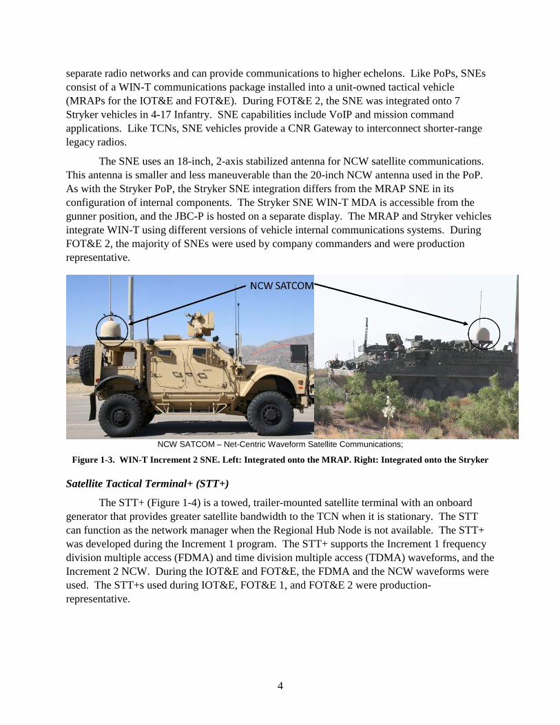
separate radio networks and can provide communications to higher echelons. Like PoPs, SNEs consist of a WIN-T communications package installed into a unit-owned tactical vehicle (MRAPs for the IOT&E and FOT&E). During FOT&E 2, the SNE was integrated onto 7 Stryker vehicles in 4-17 Infantry. SNE capabilities include VoIP and mission command applications. Like TCNs, SNE vehicles provide a CNR Gateway to interconnect shorter-range legacy radios.
The SNE uses an 18-inch, 2-axis stabilized antenna for NCW satellite communications. This antenna is smaller and less maneuverable than the 20-inch NCW antenna used in the PoP. As with the Stryker PoP, the Stryker SNE integration differs from the MRAP SNE in its configuration of internal components. The Stryker SNE WIN-T MDA is accessible from the gunner position, and the JBC-P is hosted on a separate display. The MRAP and Stryker vehicles integrate WIN-T using different versions of vehicle internal communications systems. During FOT&E 2, the majority of SNEs were used by company commanders and were production representative.
NCW SATCOM – Net-Centric Waveform Satellite Communications; Figure 1-3. WIN-T Increment 2 SNE. Left: Integrated onto the MRAP. Right: Integrated onto the Stryker
Satellite Tactical Terminal+ (STT+)
The STT+ (Figure 1-4) is a towed, trailer-mounted satellite terminal with an onboard generator that provides greater satellite bandwidth to the TCN when it is stationary. The STT can function as the network manager when the Regional Hub Node is not available. The STT+ was developed during the Increment 1 program. The STT+ supports the Increment 1 frequency division multiple access (FDMA) and time division multiple access (TDMA) waveforms, and the Increment 2 NCW. During the IOT&E and FOT&E, the FDMA and the NCW waveforms were used. The STT+s used during IOT&E, FOT&E 1, and FOT&E 2 were production-representative.

5
Figure 1-4. WIN-T STT+
Tactical Relay – Tower (TR-T)
The TR-T (Figure 1-5) is a 30-meter mast providing a relay capability to extend the range of the HNW line-of-sight communications network. One TR-T is fielded to each brigade. During the IOT&E, one TR-T was at Fort Campbell, Kentucky, and one was at Fort Bliss/White Sands Missile Range (WSMR). During the FOT&E 1 and FOT&E 2, a single TR-T at WSMR was used. The TR-T used was production-representative.
Figure 1-5. WIN-T TR-T
Network Operations and Security Center (NOSC)
The Increment 2 NOSC (Figure 1-6) provides the hardware and software infrastructure to support Soldier network management of the WIN-T Increment 2 network. The Increment 2 NOSC has two designs, one to support the brigade (NOSC-B) and another to support the division (NOSC-D). The NOSC supports communications planning, monitoring, network configuration and management, and Information Assurance.
The NOSC is transported on an FMTV and network management components are permanently housed and operated in the vehicle shelter on the FMTV. The set of network

6
management laptops in the command posts are connected to the equipment in the NOSC via tactical fiber-optic cable. The NOSC acquires transmission services from a co-located TCN and includes a trailer with an environmental control unit and generator. The NOSCs used for the IOT&E and both FOT&Es were production-representative.
Figure 1-6. WIN-T NOSC
Vehicle Wireless Package (VWP)
The VWP is a communications package designed to connect subscribers over the air to TCNs. The parent TCN provides a wireless “hot spot” for VWP-equipped vehicles. There are two VWP-equipped vehicles per TCN. The Army intends the VWP to provide wireless connectivity to Secret IP Router Network (SIPRNET) or Non-secure IP Router Network (NIPRNET) through the Local Access Waveform out to a required range of 4 kilometers. For the IOT&E and both FOT&Es, the VWPs were integrated on MRAPs. This was production representative.
Modular Communications Node – Basic (MCN-B)
The MCN-B (Figure 1-7) is a tactical fiber link that provides NIPRNET and SIPRNET access to buildings and tents up to 1 kilometer away from the parent TCN. The MCN-B transit cases are transported as loose cargo on the back of the TCN. During IOT&E and FOT&E, the MCN-B were production representative.

7
Figure 1-7. WIN-T MCN-B
Regional Hub Node (RHN)
An RHN (Figure 1-8) is a satellite ground station that operates outside of theater or “in sanctuary.” There are five RHNs in operation around the world. The RHN is designed to provide long haul tactical communications and network management services to users, such as those using WIN-T. Each RHN will be supplied with a Regional Hub Upgrade Kit, which will allow the RHN to support the NCW, as well as, Ka/Ku FDMA Satellite Communications (SATCOM) frequencies. WIN-T Increment 2 provides eight NCW modems per division to the existing regional hubs. The Army intends each RHN to have sufficient numbers of modems and transmission bandwidth to support three divisions and a corps headquarters. During WIN-T Increment 2 operational testing, the Network Service Center – Training at Fort Gordon, Georgia, replicated the support provided by an RHN.
Figure 1-8. Regional Hub Node

8
Mission Control Applications
WIN-T supports the transport of voice and data via mission control applications. During the IOT&E and both FOT&Es, the mission control applications provided by WIN-T Increment 2 on the PoP and the SNE were:
• Tactical Ground Reporting – a multimedia patrol preparation and debriefing tool.
• Advanced Field Artillery Tactical Data System Forward Observer System – allows Soldiers to plan, control, and execute fire support operations at maneuver brigade and below.
• Jabber Chat – chat service.
• Command Post of the Future (CPOF) – command and control software system for battlefield visualization, available only on the PoP for FOT&E.
• Ventrilo – a telephone service that is traditionally bundled with CPOF.
The WIN-T MDA tablet in the PoP and SNE provides users access to these applications. MRAP PoPs and SNEs are equipped with a fully functional MDA in the back and a Smart Display Unit, supplied by the JBC-P program in the front. A switch that resides between the front and back seats connects the two displays. The front display can access JBC-P directly and allow participation in-progress WIN-T phone calls. The WIN-T operator in the rear seat in an MRAP must use the WIN-T MDA in order to initiate or answer phone calls or access most WIN-T applications. Stryker PoPs and SNEs maintain separate displays for WIN-T and JBC-P.
The MDAs host two other non-WIN-T applications in addition to the applications described above. These are:
• Force XXI Battle Command Brigade and Below Joint Capability Release (JCR) and Joint Battle Command – Platform (JBC-P) to track friendly and hostile forces on the battlefield. JCR and JBC-P also provide chat capabilities.
• The Combat Net Radio (CNR) Gateway provides access to multiple, shorter-range legacy combat net radios, such as the Single Channel Ground and Airborne Radio System. The CNR Gateway is provided on SNEs and available at the TOC through the TCN.
Concept of Employment
Figure 1-9 portrays the notional concept of employment of WIN-T Increment 2 waveforms at the division and below. Each maneuver brigade has a separate NCW satellite network. A division has four maneuver brigade NCW networks plus a division-level network. The HNW line-of-sight network supports all division nodes.

9
Figure 1-9. WIN-T Increment 2 Division-Level Communications Network (Notional)
HNW – Highband Networking Waveform LOS – Line-of-Sight FDMA – Frequency Division Multiple Access SATCOM – Satellite Communications NCW – Net-Centric Waveform VWP – Vehicle Wireless Package WGS – Wideband Global SATCOM TCN – Tactical Communications Node EPLRS – Enhanced Position Location & Reporting System SINCGARS – Single Channel Ground and Airborne Radio System SRW – Soldier Radio Waveform STT+ – Satellite Tactical Terminal+ MVR BN – Maneuver Battalion CP – Command Post MVR BDE – Maneuver Brigade TOC – Tactical Operations Center BDE CDR – Brigade Commander TAC – Tactical Command Post ATH – At-the-Halt PoP – Point of Presence SNE – Soldier Network Extension NOSC – Network Operations & Security Center NOSC-D – Division / NOSC-B – Battalion

10
This page intentionally left blank.

11
Section Two Test Adequacy
Operational Testing
The Follow-on Test and Evaluation (FOT&E) 2 of the Warfighter Information Network – Tactical (WIN-T) Increment 2 was adequate to support an assessment of operational effectiveness, operational suitability, and survivability. The test was conducted in accordance with a DOT&E-approved test plan and is intended to support a Full-Rate Production Decision review scheduled for May 2015. The test focused on whether issues discovered during IOT&E and FOT&E 1 have been corrected.
The WIN-T Increment 2 program completed its Initial Operational Test and Evaluation (IOT&E) in May 2012. DOT&E issued its assessment of IOT&E in September 2012 to fulfill the provisions of Title 10, United States Code, Section 2399. That assessment found the Tactical Communications Node, Point of Presence (PoP), Net-Centric Waveform satellite communication, Colorless Core Security Architecture, Satellite Tactical Terminal+, Network Operations and Security Center, Vehicle Wireless Package, Modular Communications Node – Basic, and Joint Gateway Node operationally effective. The Soldier Network Extension (SNE), Highband Networking Waveform (HNW), and the Tactical Relay – Tower (TR-T) were not operationally effective. The WIN-T Increment 2 system overall was not operationally suitable and not survivable. The Defense Acquisition Executive issued an Acquisition Decision Memorandum on September 26, 2012, which directed the Army to conduct an FOT&E to demonstrate improved reliability for the system and improved SNE and HNW line-of-sight performance prior to a Full-Rate Production Decision.
The Army Test and Evaluation Command conducted the FOT&E during May 7-24, 2013, as part of the Network Integration Evaluation (NIE) 13.2 at Fort Bliss, Texas; White Sands Missile Range, New Mexico; and Fort Gordon, Georgia. DOT&E issued its assessment of FOT&E 1 in September 2013. The assessment found that the SNE was not operationally effective. The HNW and TR-T were not operationally effective and could not maintain an HNW network in support of brigade operations over a tactically representative area of operations. The Tactical Communications Node, the Vehicle Wireless Package, the TR-T and the Network Operations and Security Center were operationally suitable. The PoP and the SNE were not operationally suitable. WIN-T Increment 2 improved on survivability; however, there were areas that were not survivable and required further improvement. The Defense Acquisition Executive issued an Acquisition Decision Memorandum (ADM) on September 27, 2013, which directed the Army to conduct a second FOT&E (FOT&E 2) to demonstrate: (1) the PoP meets threshold reliability requirements; (2) significant reduction in the complexity of the start-up, reboot, troubleshooting, and shutdown procedures for the SNE and PoP; (3) significant reduction in the complexity of the SNE Combat Net Radio Gateway operations. The ADM directed that FOT&E 2 assess other deficiencies noted during FOT&E 1.
This evaluation is based upon the October 2014 FOT&E 2, the May 2013 FOT&E 1, the 2012 IOT&E, and developmental testing directed by the Program Manager and conducted by

12
General Dynamics at their Taunton, Massachusetts, facility. This includes two product verification tests (PVT1 and PVT2) performed during fiscal year 2014 (FY14) to verify changes aimed at addressing issues from the September 2013 ADM.
The operational test dates and the events that led up to the FOT&E 2 appear in Table 2-1.
Table 2-1. Test Schedule Activity Date
WIN-T Increment 2 New Equipment Training (NET) Courses July 14 – August 25, 2014
Operational Test Readiness Review (OTRR) 2 August 15, 2014
Validation Exercise (VALEX) August 25 – September 19, 2014
Instrumentation Data Validation August 25 – September 19, 2014
Garrison Communications Exercise (COMMEX) 22-26 September 2014
Data End to End September 22 – October 4, 2014
Baseline Inventory 24 September 2014
Unit Preparation Week September 29 – October 2, 2014
Field COMMEX October 3-6, 2014
Pilot Test October 7-11, 2014
OTRR 3 October 15, 2014
Record Test October 15 – November 2, 2014
Authenticated Database Delivery November 2014
The test unit, 2nd Brigade, 1st Armored Division, at Fort Bliss/White Sands Missile
Range, is a heavy brigade combat team that provided a brigade headquarters and six battalions equipped with WIN-T Increment 2. The Network Service Center – Training at Fort Gordon replicated the support provided by a Regional Hub Node.
Test Scenario
The test units executed decisive action operations that included offensive, defensive, and stability missions employed at-the-halt and on-the-move. The Brigade Modernization Command issued warning orders, fragmentary orders, and operations orders to transition the test through scenario phases. Each phase was designed in accordance with the requirements of the 72-hour Operational Mode Summary/Mission Profile. The 19-day operational test included the following mission and scenarios.
• Mission: 2nd Brigade, 1st Armored Division initially executed Combined Arms Maneuver and Wide Area Security operations in accordance with a six phased operational plan.
• Scenario Concept:
− Phase 1 (Pilot). The Armored Brigade Combat Team (ABCT) conducted reception, staging, onward-movement and integration; prepared for combat; and

13
conducted Wide Area of Security (WAS) to secure villages. This phase consisted of brigade and battalion command post exercise, platoon situational training exercises, interaction with the Attican National Army (ANA) representing the host nation military and host nation civilians, and attacks against Attican Liberation Army (ALA) (representing the opposing force) strongholds.
− Phase 2a (October 15 – 18, 2014). The ABCT conducted WAS to defeat the ALA forces and reestablished the Attican government in the Area of Operation. This phase consisted of WAS, company level raids, and cordon and searches. The threat was the ALA in villages.
− Phase 2b (October 19 – 22, 2014). The ABCT conducted Combined Arms Maneuver and WAS in AO Bliss to disrupt the ALA and rogue Attican forces. The ALA massed and seized key terrain. Rogue ANA forces occupied and defended Condron Airfield, while rogue Attican forces attacked from Las Cruces through the Adobe Village (A–V) Gap. ABCT conducted operations to isolate ALA by conducting CO raids and cordon and searches.
− Phase 3a (October 23 – 26, 2014). The ABCT conducted Combined Arms Maneuver and WAS to disrupt ALA and rogue Attican forces. The ABCT attacked to defeat rogue ANA and ALA strongholds in AO Bliss. A mechanized battalion attacked to destroy Attican forces in the west. A Stryker battalion attacked to destroy ALA and Attican remnants in the east. A cavalry squadron isolated and eroded ALA combat power.
− Phase 3b (October 27–30, 2014). The ABCT defended against Ellisian attack and secured villages. The ABCT (–) defended against Ellisian attack from west and attacked ALA strongholds. A Stryker battalion attacked to secure Zamania. A mechanized CO team defended against Ellisian attack through the A–V Gap. A Cavalry squadron (–) conducted force-oriented zone reconnaissance in support of the brigade.
− Phase 3c (October 29 –November 2, 2014). The ABCT secured borders and prepared for future operations. The ABCT consolidated position on Bliss. A mechanized battalion secured brigade western boundary. A Stryker battalion conducted security operations in vicinity of Zamania. A cavalry squadron conducted screens along the brigade’s northern boundary preventing rogue ANA and ALA elements from entering the brigade Area of Operation.
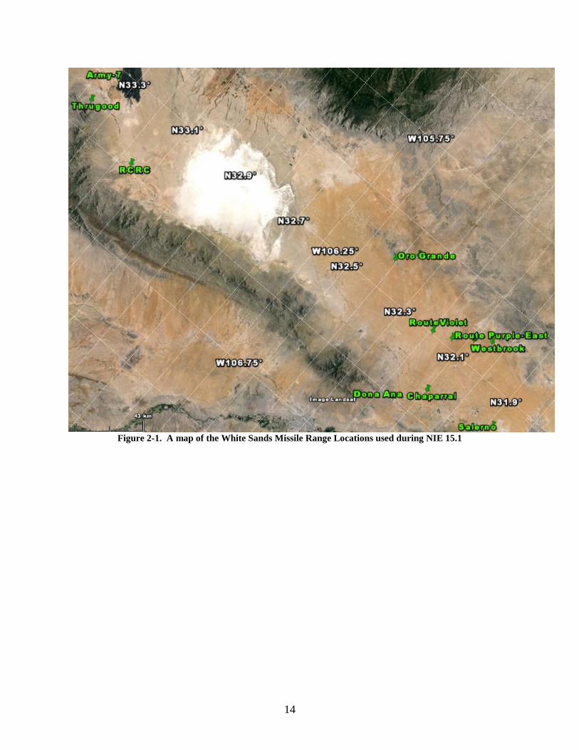
The brigade’s movement of Tactical Operations Centers (TOCs) and units allowed the FOT&E 2 to test the on-the-move capability of WIN-T Increment 2. Figure 2-1 shows a map of the primary TOC locations used during NIE 15.1. Table 2-2 provides a summary of executed unit movements during the WIN-T Increment 2 FOT&E 2.
14
Figure 2-1. A map of the White Sands Missile Range Locations used during NIE 15.1

15
Table 2-2. WIN-T Increment 2 FOT&E 2 Executed Unit Movements UNIT Location 1 Move 1 Location 2 Move 2 Location 3 Move 3 Location 4
Brigade Main TAA Salerno
Oct 28
Route Purple-
East
Brigade Tactical
Operations Center
TAA Salerno
Oct 27
Route Purple-
East
Oct 29
RCRC-S
Oct 31
Route Purple-
East
Brigade Special Troops
Battalion TAA Salerno
Oct 28
Route Purple-
East
1-1 Cavalry Squadron Oro Grande Oct 22
Route Red
Oct 29
RCRC
Oct 31 Route Red
(Range 100)
1-6 Infantry Battalion Dona Ana Oct 22
Route Violet
4-17 Infantry Battalion Westbrook Oct 22
Oro Grande- East
Oct 29
Thurgood Canyon
4-27 Field Artillery Battalion
Dona Ana Oct 26
McGregor Range-South
Oct 28
Pad 25 McGregor
Range
47 Brigade Support Battalion
McGregor Range
Complex
Oct 30
Route Purple-
East
TAA – Tactical Assembly Area; RCRC – Rhodes Canyon Range Complex; RCRC-S-Rhodes Canyon Range Complex-South
Information Assurance
During the FOT&E 2, the Army Research Laboratory Survivability/Lethality Analysis Directorate (ARL/SLAD) conducted a Cooperative Vulnerability and Penetration Assessment on WIN-T Increment 2. The Army Threat Systems Management Office with support from ARL/SLAD executed an Adversarial Assessment. These tests were performed in accordance with the DOT&E memorandum “Procedures for Operational Test and Evaluation of Information Assurance in Acquisition Programs,” dated August 1, 2014.
Electronic Warfare
During the FOT&E 2, Electronic Warfare testing consisted of open-air jamming and direction finding operations. The Threat Systems Management Office provided and operated the jamming, direction finding, and GPS-imitating equipment to support the multiple 72-hour scenarios in an Electronic Warfare environment. All threats portrayed were in accordance with the accredited threat training support package for WIN-T Increment 2.

16
System Support
During the WIN-T Increment 2 FOT&E 2, the Program Office provided three Field Service Representatives (FSRs) for the WIN-T configuration items and one additional FSR for the Satellite Tactical Terminal+ satellite trailers.
Test Limitations
The Army conducted the WIN-T Increment 2 FOT&E 2 in accordance with the DOT&E-approved test plan. The test included the following limitations.
• The Army used three Stryker PoPs and seven Stryker SNEs during the test. Although deemed an appropriate sample, a fully equipped Stryker BCT would employ 10 PoPs and 44 SNEs.
• Due to Federal Aviation Agency and Federal Communication Commission restrictions, the Army was not able to jam the Net-Centric Waveform satellite uplink. The Army was not able to develop a method for simulating the loss of satellite capability in a threat representative way.

17
Section Three Operational Effectiveness
During the May 2013 FOT&E 1, DOT&E assessed whether changes made to WIN-T Increment 2 following IOT&E improved the operational effectiveness of the Soldier Network Extension (SNE), Highband Networking Waveform (HNW), and Tactical Relay – Tower (TR-T), while maintaining the operational effectiveness of the remainder of the system. During FOT&E 1, the following configuration items were operationally effective:
• Net-Centric Waveform (NCW)
• Tactical Control Node (TCN)
• Point of Presence (PoP)
• Vehicle Wireless Package (VWP)
• Network Operations and Security Center (NOSC)
• Satellite Tactical Terminal+ (STT+)
• Colorless Core Security Architecture
During the May 2013 FOT&E 1, the following configuration items were not operationally effective:
• SNE
• HNW line-of-sight waveform
• TR-T
During FOT&E 2, DOT&E assessed performance outlined in the September 27, 2013, Defense Acquisition Executive Acquisition Decision Memorandum to include deficiencies noted in the DOT&E FOT&E 1 report, and the integration of PoP and SNE into Stryker. During FOT&E 2, the following configuration items were operationally effective:
• SNE with Combat Net Radio (CNR) Gateway
• NCW, reassessed due to FOT&E network outages
• PoP and SNE integrated into Stryker
The following configuration items were not operationally effective:
• HNW line-of-sight waveform and network management tools
• TR-T

18
Network Usage
The HNW and NCW traffic (percentages) for IOT&E, FOT&E 1, and FOT&E 2 are shown in Figure 3-1.
Figure 3-1. Amount of NCW and HNW Traffic at IOT&E, FOT&E 1, and FOT&E 2
The FOT&E 2 “other” traffic includes multi-waveform combinations of HNW/NCW traffic. FOT&E 2 provided a higher median HNW traffic load at 1.0 Megabits per second (Mbps) than FOT&E 1 (516 Kilobits per second (Kbps)). During FOT&E 2, HNW carried a higher portion of user traffic compared to FOT&E 1, although the majority of this HNW traffic originated within a transmission range of 1 kilometer or less. The percent of user traffic using HNW and NCW networks is dependent on the operations being performed, the location of the Tactical Operations Centers (TOCs), and the network configuration determined by the Brigade S6.
WIN-T Increment 2 uses a large amount of data throughput to support the functions of the colorless core network. As captured with FOT&E 2 data instrumentation, the unit transmitted 846 Gigabytes (Gbytes) of data over the WIN-T colorless core network between PoPs, TCNs, and SNEs. The colorless core network supports both Secret Internet Protocol Router (SIPR) and Non-secure Internet Protocol Router (NIPR) network traffic. Within the colorless core, WIN-T supported 396 Gbytes of SIPR user traffic between PoPs, TCNs, and SNEs.1 NIPR network traffic provided a small percentage of overall network load. SIPR traffic provides the voice, video, and data throughput used to support the unit’s mission. When SIPR traffic is transmitted on the colorless core, it expands by a factor of approximately two because of network overhead, encryption, and tunneling when passed over the colorless core.
1 Due to instrumentation and unknowns in the network architecture, this does not capture all traffic. Although direct
comparison is impossible, the majority of the difference is due to the expansion necessary to take data from the SIPR to colorless side. The intention is to express the expansion of SIPR traffic on the colorless core and the perceived data throughput by the user.

19
During FOT&E 2, NCW and HNW demonstrated connectivity similar to IOT&E and FOT&E 1. Figure 3-2 shows the number of WIN-T Increment 2 platforms connected to the Brigade Commander’s PoP during IOT&E, FOT&E 1 and FOT&E 2.
Figure 3-2. Brigade Commander’s PoP Network Links during IOT&E, FOT&E 1, and FOT&E 2
Temporary network drops are depicted as straight vertical lines, which represent reduced connections within the WIN-T network. When the brigade commander’s vehicle was turned off, the connectivity plot (red line) forms a V-shaped notch in the FOT&E 2 line graph. The stability of the number of connections maintained by the brigade commander’s PoP tends to be similar to IOT&E with momentary drops in the number of NCW routes. The brigade commander’s experience (as representative of a PoP mobile user) remains similar to IOT&E and FOT&E 1.

20
Along with supporting Soldier’s mission command applications, WIN-T Increment 2 uses a large amount of data throughput to maintain the network and network services. Figure 3-3 shows the percentage of SIPR traffic used to support various applications for the SNE (left) and PoP (right).
Figure 3-3. SIPR Traffic Observed during FOT&E 2
The distribution of application traffic provides the Soldier’s experience and use of the network. The applications with the highest demands on WIN-T include the CNR Gateway, Information Assurance, Active Directory, Command Post of the Future, Tactical Ground Reporting (TIGR) System, and Network Management services. WIN-T Increment 2 uses a significant portion of SIPR traffic (50 to 64 percent) maintaining the network with Information Assurance, Network Management, and Active Directory applications. Considering the discussion of SIPR to colorless core expansion, 25 to 30 percent of the total load supported by the colorless core is mission traffic.
During FOT&E 2, the usage of NCW was similar to that observed during IOT&E and FOT&E 1. The total (offered plus received) load for the mobile configuration items (TCN, PoP, and SNE) is listed in Tables 3-2 and Table 3-3, depicted by the median throughput values at-the-halt and on-the-move. During FOT&E 2, the similarity of WIN-T usage to past operational tests was due to the increased usage of NCW following IOT&E. This was due to the adjusted HNW routing algorithm (to combat “cycling” outlined in the IOT&E report), which reduced HNW use during FOT&E 1, as well as the closer density of units during FOT&E 2, which increased short-range at-the-halt HNW. As shown in Table 3-3, on-the-move HNW provided little support for TCNs and PoPs compared to NCW.

21
Table 3-2. Median NCW Network Loads (Kbps) during IOT&E, FOT&E 1, and FOT&E 2
IOT&E FOT&E 1 FOT&E 2
At-The-Halt
SNE 17 37 33
POP 12 29 30
TCN 45 275 230
On-the-Move
SNE 16 36 34
POP 21 33 38
TCN 63 112 110
Table 3-3. Median HNW Network Loads (Kbps) during IOT&E, FOT&E 1, and FOT&E 2
IOT&E FOT&E 1 FOT&E 2
At-The-Halt POP 23 3 8
TCN 137 18 121
On-the-Move POP 6 17 2
TCN 25 8 3
Network-Centric Waveform (NCW)
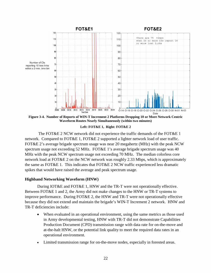
During FOT&E 2, the NCW satellite network was operationally effective and provided consistent connectivity to NCW-equipped WIN-T Increment 2 configuration items. During IOT&E, FOT&E 1, and FOT&E 2, the NCW network experienced momentary outages (30 seconds or less) where users lost 10 or more NCW connections; however, these disruptions did not affect the Soldier’s mission. During FOT&E 1, the NCW experienced two severe network outages, which disrupted WIN-T Increment 2 satellite communications for a period of 1 hour each. The Army determined the problem was due to disadvantaged users requiring increased NCW power and fixed this deficiency. Figure 3-4 shows the number of nodes with dropped routes, which is defined as losing 10 or more routes within a 2-minute time period (FOT&E 1 on left, FOT&E 2 on right). During FOT&E 2, the NCW network was more stable with the number of nodes reporting more than 10 dropped routes in a 2-minute period being less than 30 per incident throughout FOT&E 2. Compared to the outage periods during FOT&E 1 (where nodes reported 10 or more dropped routes 120 times or more within a 2-minute period), NCW demonstrated an improvement in stability during FOT&E 2.
22
Figure 3-4. Number of Reports of WIN-T Increment 2 Platforms Dropping 10 or More Network Centric
Waveform Routes Nearly Simultaneously (within two minutes)
Left: FOT&E 1, Right: FOT&E 2
The FOT&E 2 NCW network did not experience the traffic demands of the FOT&E 1 network. Compared to FOT&E 1, FOT&E 2 supported a lighter network load of user traffic. FOT&E 2’s average brigade spectrum usage was near 20 megahertz (MHz) with the peak NCW spectrum usage not exceeding 52 MHz. FOT&E 1’s average brigade spectrum usage was 40 MHz with the peak NCW spectrum usage not exceeding 70 MHz. The median colorless core network load at FOT&E 2 on the NCW network was roughly 2.33 Mbps, which is approximately the same as FOT&E 1. This indicates that FOT&E 2 NCW traffic experienced less dramatic spikes that would have raised the average and peak spectrum usage.
Highband Networking Waveform (HNW)
During IOT&E and FOT&E 1, HNW and the TR-T were not operationally effective. Between FOT&E 1 and 2, the Army did not make changes to the HNW or TR-T systems to improve performance. During FOT&E 2, the HNW and TR-T were not operationally effective because they did not extend and maintain the brigade’s WIN-T Increment 2 network. HNW and TR-T deficiencies include:
• When evaluated in an operational environment, using the same metrics as those used in Army developmental testing, HNW with TR-T did not demonstrate Capabilities Production Document (CPD) transmission range with data rate for on-the-move and at-the-halt HNW, or the potential link quality to meet the required data rates in an operational environment.
• Limited transmission range for on-the-move nodes, especially in forested areas.

23
• Low quality (measured by link burst rate) of at-the-halt links provided limited range for transmitting data.
• In the absence of the NCW satellite, HNW did not maintain the network.
• Poor use of TR-T and Range Throughput Extension Kit (RTEK) antennas to support network extension.
• Lack of stability for longer distance links can interfere with latency and jitter intolerant applications, and add to network congestion.
• Network Management tools did not support effective use of TR-T and RTEK.
HNW is a Time Division Multiple Access (TDMA) terrestrial line-of-sight waveform. TDMA is a channel access method that allows multiple users to share a single frequency channel by dividing the signal into different timeslots. HNW communications are divided into 10 millisecond intervals termed “epochs.” Each epoch is divided into 160 time frames, and 150 of those time frames can be allocated to neighboring nodes on an on-demand basis to support the transfer of data traffic. The more time frames a node is assigned, the more traffic it can send over an HNW radio link. The remaining 10 time frames are reserved for network overhead traffic necessary to manage the waveform. The expected data rate is the burst rate (R) , multiplied by the fraction of time allocated to sending user traffic, M(Tf- X), where M is the number of time frames, Tf, is the length of the time frame, and X is the amount of time allocated to preamble and overhead bytes and propagation delay. The burst rate is defined internally by the radio and depends on the physical layer link quality.
For HNW, the “burst rate” is a measure of link quality (not data throughput) and can have eight values: 6 Mbps, 9 Mbps, 12 Mbps, 18 Mbps, 24 Mbps, 36 Mbps, 48 Mbps, and 54 Mbps. A 54 Mbps link is the highest quality link and is capable of sending the most traffic. As the lower burst rates provide poor quality link, WIN-T Increment 2 selects the NCW satellite network for routing data when the HNW burst rates measure 6 Mbps or 9 Mbps. This allows the NCW satellite to provide a higher data rate and avoid the HNW/NCW cycling problem observed during IOT&E.

24
Figure 3-5. Estimated Data Rate by Number of Time Slots for a Given Burst Rate (in Mbps)
HNW link data rates are determined by combining the link’s burst rate (link quality) with allotted time slots. The relationship between a burst rate and time slots presents a linear function to determine estimated data rates as shown in Figure 3-5. Based on FOT&E 2 data, each colored line represents a link burst rate, listed in the legend from 0 to 54 Mbps. The colored points represent the data samples from FOT&E 2 used to determine the link burst rate to the data rate graph. To draw examples from Figure 3-5, if the network allots 50 time slots to a 6 Mbps burst rate link (shown in green), the resulting data rate is 900 Kbps. If the same 50 time slots are allotted to a 54 Mbps burst rate link (shown in purple), the resulting data rate is 12 Mbps (over 12 times the data rate of the 6 Mbps burst rate link).
The WIN-T CPD, approved October 17, 2014, states that WIN-T Increment 2 should provide high-capacity, line-of-sight, ground-to-ground networking radio communication for maneuver battalion, brigade combat team command posts, and division headquarters stationary with the auxiliary flat-plate antenna 27 Mbps at 12 kilometers (10 meter mast) and mobile 18 Mbps at 2 kilometers (threshold). The CPD refers to the throughput rates as the shared transmit/receive data rate available at the input/output of the radio or transmission device, and states ranges are dependent on line-of-sight and do not include blockages. HNW CPD data rate performance provides a means to characterize expectations for an HNW network to discuss deficiencies noted during FOT&E 2.
HNW is a shared data rate by design, which means the network allocates more time slots to links needing to transfer more data. Therefore, during FOT&E 2, DOT&E assessed HNW to determine demonstrated data rates, and potential data rates based upon demonstrated link quality (burst rates) and possible time slot allocations. DOT&E evaluated demonstrated and potential performance during operational test in a manner similar to the Army’s HNW developmental tests (i.e., assessing the CPD requirement for data rate at the stated distance). During the 2012 Production Qualification Testing – Government (PQT-G), Army developmental testing assessed

25
WIN-T Increment 2 as meeting the data rate at distance requirements by testing two nodes in isolation, not part of a larger network, under optimum conditions, which included measured distance, no terrain or vegetation blockage, and unlimited time slots to support higher data rates. Although the use of both stationary and mobile communications would be expected in an operational network, PQT-G did not test both on-the-move and at-the-halt CPD data rate requirements at the same time because there were not enough time slots in test setup to support both links.
Figure 3-6. Estimated Data Rate by Number of Time Slots for a Given Burst Rate
(Dashed lines represent the requirements.)
Table 3-4. Number of Time Slots Needed to Meet CPD Requirements of 27 Mbps and 18 Mbps for the TCN and PoP
Although WIN-T Increment 2 demonstrated the CPD data rate requirements during the two-node, point-to-point PQT-G developmental testing in 2012, due to the limited number of time slots available across a brigade network, the WIN-T Increment 2 HNW network shows little potential to meet its CPD data rate requirements in an operationally realistic network. As discussed above, for a link to pass data, the network allocates its limited time slots, on demand,
6 9 12 18 24 36 48 54 Notes
27 983 656 492 328 246 164 123 110Command Post (TCN) Requirement (27Mbps)
18 656 437 328 219 164 110 82 73Mobile (PoP) Requirement (18Mbps)
13.5 492 328 246 164 123 82 62 55CP Requirement as bidirectional, single link
9 328 219 164 110 82 55 41 37OTM Requirement as bidirectional, single link
Burst Rate (Mbps)
Des
ired
Dat
a R
ate
(Mbp
s)
Required Time Slots for a single link

26
to enable the HNW link to pass data. To examine HNW’s ability to support data rates, DOT&E has to examine link quality (measured in link burst rates) and allocated time slots. Figure 3-6 shows WIN-T Increment 2 effective HNW link data rates by time slots for given burst rate values compared to the CPD requirements. Viewing these data, only the best quality HNW links (measured by link burst rate) can support CPD data rates. Given the network limitation of 150 time slots, Table 3-4 shows the number of times slots needed to meet the 27 Mbps and 18 Mbps CPD requirements for potential HNW link burst rate values. DOT&E also examined bidirectional values (half the CPD requirement) to determine time slots required for paired transmit and receive nodes attempting to use the CPD data rates. The grayed-out values indicate those combinations that are not allowed by the waveform because the number of time slots is greater than the number available. Red values indicate time slot allocations that could support a single link data rate but exceed the observed best practice limit of 50 time slots per node (as used by network managers during FOT&E 2). Using more than 50 time slots may support a single HNW link’s desired data rate, but this use increases the risk of not supporting time slot demand across the rest of a brigade HNW network. (Using this value is not operationally realistic as it may not leave sufficient time slots to support the remaining HNW network with reasonable data throughput). Table 3-4 shows that the CPD at-the-halt TCN, command post data rate requirement of 27 Mbps and the mobile PoP data rate requirement cannot be met without exceeding the best practice number of time slots of 50. When this number is exceeded, the HNW network is at risk of not supporting brigade data, regardless of distance. In the case of bidirectional links, these restrictions still remain since the time slot allocation is doubled to support each HNW node on the link.
The maximum number of time slots that can be allocated to any HNW node is set by the unit network operations to ensure available bandwidth across the brigade. During FOT&E 2, the typical number of time slots was 50 for TCNs, and 25 to 50 for PoPs. At times, the Network Management Soldiers would change these values depending on unit activity—DOT&E views this typical time slot limitation as their best practice—necessary and operationally realistic. As shown in Table 3-4, the number of slots required to meet the CPD requirements for a single unidirectional link (full CPD requirement) in all instances is greater than 50. This indicates that the number of time slots allocated to a single link necessary to meet CPD requirements is excessive. In the case of unidirectional links, the doubling of timeslots to support full link data rate results in the same excessive allocation. The CPD requirements can be met, but under conditions that are not operationally realistic. These unrealistic conditions are compounded when recognizing the brigade would require stationary command post TCN and mobile PoP data rates at the same time to support combat operations.

27
Figure 3-6(a). TCN-to-PoP, Mobile: Percentage of Links at a Burst Rate with Distance
Figure 3-6(b). TCN-to-TCN, Command Post: Percentage of Links at a Burst Rate with Distance
During FOT&E 2, WIN-T Increment 2 did not demonstrate its CPD HNW data rate requirements or demonstrate the potential HNW link burst rates required to support its CPD requirements. The FOT&E 2 HNW network supported data rates well below the CPD requirements. The maximum TCN to PoP mobile data rate was 12 Mbps and was established for 10 seconds, which served as the single example of a PoP achieving data rates in excess of 9 Mbps. The TCN to TCN command post links did not demonstrate an effective data rate of 12 Mbps, much less the 27 Mbps CPD data rate requirement at any range. Since HNW is a demand assigned waveform, DOT&E will examine HNW link burst rates and their potential to meet HNW CPD requirements, data rates at distances, considering various time slot allocations. Figure 3-6 (a) and (b) shows FOT&E 2 HNW links with their recorded percentage of burst rates (link quality) at distance ranging from 0 to 20 kilometers. The PoP to TCN mobile values are shown in 3-6(a) and the TCN to TCN command post values are shown in 3-6(b). Each figure includes a dashed line to indicate the CPD requirement distance, 2 kilometers for PoP and 18 kilometers for the TCN. The FOT&E 2 HNW link burst rates of 54 Mbps and 48 Mbps, which provide the potential to meet the CPD data rate requirements of 18 Mbps (mobile) and 27 Mbps (command post), are colored red and dark red. As shown in Figure 3-6(a), TCN to PoP mobile links demonstrated the potential link burst rates 15 percent of the time at 2 kilometers. As shown in Figure 3-6(b), TCN to TCN command post links demonstrated the potential HNW link burst

28
rate of 48 Mbps or 54 Mbps 15 percent of the time at 4.5 kilometers, dropped to no potential, and then showed a brief 5 percent potential at 12 kilometers. During FOT&E 2, WIN-T Increment 2 demonstrated neither its CPD requirements nor a significant potential (using excessive time slots) to meet its requirements for HNW data rates at distance.
Figure 3-7(a). Network Connectivity of Moving PoPs during IOT&E at White Sands Missile Range (WSMR)
Figure 3-7(b). Network Connectivity of Moving PoPs during FOT&E at WSMR
Figure 3-7(c). Network Connectivity of Moving PoPs during FOT&E 2 at WSMR

29
Figure 3-8. HNW Link Burst Rates (Single Hop) of Moving PoPs during FOT&E 2 at WSMR
HNW does not provide transmission range to support mobile subscribers. Figure 3-7(a-c) illustrate the connectivity of the HNW line-of-sight network to support PoPs while they are on-the-move (at speeds greater than 5 miles per hour (mph)). Data in the figures were accumulated over the duration of WIN-T Increment 2 IOT&E, FOT&E 1, and FOT&E 2 in the desert terrain of Fort Bliss, Texas, and White Sands Missile Range (WSMR), New Mexico. All figures show that Soldiers rely upon NCW satellite for the majority of the mobile user data traffic. At distances greater than 10 kilometers, TCNs and PoPs are connected for the most part by the NCW satellite. At close ranges of 1 kilometer or less, HNW is used almost 80 percent of the time, of which single-hop HNW was used 60 percent of the time. Figure 3-8 shows the single-hop HNW link burst rates (link quality) of the HNW portion of mobile data traffic at distance during FOT&E 2. While the percentage of HNW usage decreases at distance, the links decrease in data rate potential, produce links that cannot transfer data, and become intermittent in nature. In particular, even at shorter ranges less than 5 kilometers when HNW use is greatest, link burst rates decrease rapidly and do not provide substantial data rates. At IOT&E and FOT&E 2, the network’s use of multi-hop HNW was more frequent. During FOT&E 1, network operations placed more restrictions on the waveform to avoid the “cycling” witnessed during IOT&E. Multi-hop HNW performance by link segment is similar to single-hop, but overall data throughput is reduced as the data traverses two or more HNW links.

30
Figure 3-9. Network Connectivity of Moving PoPs during IOT&E at Fort Campbell
HNW does not provide support for mobile users when transmitting in vegetation. During IOT&E, HNW was used in the forested environment at Fort Campbell, Kentucky. Figure 3-9 illustrates the effective HNW transmission range at Fort Campbell. Soldiers using HNW in Fort Campbell’s forested terrain experienced the loss of HNW at less than 2.5 kilometers, with most use occurring at less than 1 kilometer. As no improvements were made to the HNW radio, no additional testing in forested areas was conducted during either FOT&E 1 or FOT&E 2. The poor transmission range performance of HNW demonstrated during IOT&E at Fort Campbell is representative of the system in forested terrain.
Figure 3-10. Offered Load per day between TCNs
Figure 3-10 shows the FOT&E 2 user traffic load per day between TCNs (command posts). The black line shows the total traffic load per day. Most of the traffic over HNW during FOT&E 2 was between stationary TCNs. The bar chart is divided in color by the HNW link distance between the TCNs. The three distance categories, “Collocated”, “Near”, and “Far” are

31
defined as less than 1 kilometer, 10 kilometers, and over 10 kilometers respectively.2 An inset bar chart shows just the traffic that was supported by the TR-T. The legend provides the total data supported by category during the test.
Table 3-4. Gbytes of Traffic on HNW and NCW at Collocated, Near, and Far Distances and Percentage of Traffic over NCW and Percentage of HNW Traffic over the TR-T
When supporting command posts, the HNW network for the most part supported
collocated TOCs and at further distances, the NCW satellite network carried the majority of network traffic. HNW carried 63 percent of the inter-TOC traffic, but 72 percent (245 Gbytes out of 344 Gbytes) of the HNW TOC traffic was between collocated TOCs within a distance of one kilometer or less. At distances of 1 kilometer or less, there are other communication methods that might be more appropriate due to size and manning requirements. At “near” distances (between 1 and 10 kilometers), 27 out of the 44 GBytes of colorless traffic supported by HNW used the TR-T. Table 3-4 shows the amount of NCW and HNW traffic observed at these three distances along with the percentage of traffic over NCW, and the percentage of HNW traffic that transmitted single hop, went over another TCN, or was supported by the TR-T. At shorter distances, almost all of the traffic is supported by HNW without use of the TR-T. By 10 kilometers and the threshold of “near”, HNW is still supporting most of the unit traffic, but the TR-T is used to relay more of the traffic. At “far” distances (greater than 10 kilometers), almost all of the unit traffic (81 percent) is supported by the NCW satellite with 61 percent of the remaining HNW traffic (19 percent of total) supported by the TR-T. Although HNW does not have the physical design to provide reliable support at “far” distances (greater than 10 kilometers), the brigade’s use of the TR-T is necessary to maintain its line-of-sight HNW network.
In the absence of satellite communications, HNW will, of necessity, be the primary means the WIN-T system will attempt to use to transmit data. The availability of satellite communications is not assured under all possible combat scenarios. Satellite communications is limited in certain terrain and vegetation, and can be removed or disrupted by an enemy with the capability to jam satellite communications or conduct successful computer network attack. Available frequency spectrum to support satellite communications is limited based on a unit’s location in the world; this limitation is compounded with the increased demand of larger formations (e.g., brigade, division, and corps). WIN-T Increment 2 is designed to use HNW line-of-sight terrestrial communications to provide network support for unit missions in combination with the NCW satellite network.
2 These distances are rounded down to the nearest kilometer. The collocated distances also include some data where distances
could not be determined with instrumented data but should be less than 1 kilometers, due to knowledge of TOC locations at the time.
NCW Single Hop TCN TR-T Percent NCW Percent TR-TColocated 4 207 38 0 1.58% 0.13%
Near 1 32 6 6 2.37% 13.25%Far 180 4 12 27 80.71% 61.86%

32
When NCW satellite is not available, HNW is not able to maintain the brigade’s network. The two NCW outages experienced during FOT&E 1 resulted in a disconnected network with limited HNW connectivity among the widely dispersed elements of a brigade. Per the FOT&E 1 report, during the two observed outages, three to four of the brigade’s eight HNW-dependent TCN command posts were separated from the brigade’s network.
The brigade’s use of a single TR-T was not effective to extend the HNW network. During IOT&E, FOT&E 1 and FOT&E 2, Soldiers routinely attempted to use HNW to connect command posts at distances greater than the 12-kilometer range required by the CPD. In addition, the HNW radio demonstrated poor transmission range. The Army did not increase the number of TR-Ts assigned to the WIN-T Increment 2 brigades (see recommendation in both the IOT&E and FOT&E 1 report). A single TR-T was used during IOT&E, FOT&E 1, and FOT&E 2, consistent with the Army’s basis of issue plan. With only one TR-T, the brigade is not able to maintain long-range HNW connectivity within its area of operations.
Figure 3-11. The Line-Of-Sight (blue) and first Fresnel Zone Paths for Two TCNs at 12 Kilometers
Distance
The CPD range of 12 kilometers for two, 10-meter mast TCN antennas is challenged by physical limitations of HNW frequency spectrum. As shown in Figure 3-11, the radio transmission (represented by the first Fresnel zone) of a 12-kilometer link between two TCNs receives significant blockage from the curvature of the earth on flat terrain.3 To achieve such distances, the HNW waveform must avoid terrain and vegetation that can interfere with its transmission or employ a TR-T (for higher antenna height). HNW is not a reliable means of communication at these distances.
3 The frequency used is 4.9 gigahertz (GHz). The altitude of 1,200 meters is approximately the altitude of the Salerno site on
WSMR. The full height used for the antennas was 12.8 meters. The additional 2+ meters allow for the approximate height of the transport vehicle on which the TCN mast is mounted.

33
Figure 3-12. Amount of Data Sent by Stationary TOCs over the TR-T during the Test versus Burst Rate
During FOT&E 2, the TR-T provided links that were of low quality, and the brigade made little use of the range-extending RTEK antenna. Each TCN maintains one RTEK which can improve one HNW link of the supported command post. The use of the RTEK needs to be prioritized by the network operations to optimize the HNW network. During FOT&E, the brigade made minimal use the RTEK, and this usage does not allow conclusions as to RTEK improvements to the overall HNW network. Figure 3-12 shows the amount of data that was sent over the TR-T at different HNW link burst rates. The data is further divided into whether that link used the RTEK flat panel antenna or not. The Brigade Main TOC used an RTEK-to-RTEK link to transmit data to the TR-T, and this use of the RTEK supported a total of 16 Gbytes of user traffic. Traffic sent over the TR-T using a HRFU link totaled another 17 Gbytes of traffic. With the use of the TR-T and RTEK, the HNW link burst rates appear improved, but did not demonstrate maximum burst rates. The Army should increase the usage of RTEK antennas to improve HNW performance and emphasize RTEK use within network management tools.
Figure 3-13 shows contributions of the TR-T at FOT&E 1 during the Network Integration Evaluation 13.2. In order for two platforms to be connected by HNW through the TR-T, the links from the TR-T to each platform required link burst rates above 12 Mbps. The median single-hop burst rates between TCNs and the TR-T are shown at the beginning of the test (left) and near the end of the test (right). Dotted lines indicate nodes with no HNW connections. The brigade’s command posts are labeled.
At the beginning of FOT&E 1 (Figure 3-13, left side), the TR-T did not provide increased connectivity of the HNW network. All the nodes connected to the TR-T maintain stronger single-hop (direct) links between other HNW TCNs. The TR-T is not able to connect the Tactical Command Post or TOC to the Brigade Support Battalion (BSB) TCN (to the south) or the maneuver battalion TCNs (to the north). Dashed lines indicate no HNW links, only the
0
2
4
6
8
10
12
14
Sent
Tra
ffic
(Gby
tes)
Burst Rate
TR-T Data sent
TR-T (RTEK)TR-T (HRFU)

34
NCW satellite. During the end of FOT&E 1 (Figure 3-13, right side), the TR-T did provide connectivity to distant nodes such as Tactical Command Post and 1/1, but the link burst rates were too low for the HNW to be used. In both cases, there are isolated battalion TCN nodes that could not rely on HNW for connection to either the brigade command post or other battalion TCNs.
During FOT&E 2, the TR-T did not provide significant additional HNW connectivity. Figure 3-14 shows the HNW links on October 18, 2014, following the first deployment of the TR-T. The colors of the lines represent the median burst rate between those TCNs. The right-hand plot is an inset zoom of the region near the brigade command post. The brigade TAC, TOC and the Brigade Special Troop Battalion (BSTB) are located at Salerno, within 217 meters of each other, and maintain the highest link burst rate of 54 Mbps. The distance from Salerno to Dona Ana, where 1-6 and 4-27 are located, is 33 kilometers. Line-of-sight to 1-6 and 4-27 from the brigade is blocked by terrain. The distance from Salerno to Westbrook, where 4-17 is located, and McGregor-South, where the BSB is located, is 29 and 27 kilometers, respectively. The TR-T is located at Chaparral, the highest elevation located in the middle of the three TOC locations. The 1-1 was beyond line-of-sight connectivity at Oro Grande. The TCNs did not move during the day, which provided a stable environment for link establishment during the day.
Despite this advantageous setup, the TR-T was not able to provide reliable connectivity. 4-27 and 1-6 communicated through the TR-T because of terrain blockage, yet only 50 percent of the user traffic from brigade command post to 4-27 and 1-6 used HNW over the TR-T. With a poor link burst rate of 9 Mbps, the brigade is on occasion able to communicate directly with 4-17 and the BSB. HNW, extended with the TR-T, supported 15 percent of the traffic from brigade to the BSB and 25 percent of the traffic from the brigade to 4-17. The NCW satellite network supported the remaining unit traffic.
HNW is not stable at distances. Figure 3-14 shows the intermittent nature of HNW by displaying which waveform (HNW or NCW) was used during the day of October 18th to communicate between the brigade command post and 1-6. The HNW connection (shown in red) was intermittent throughout the day, and the connectivity was not symmetric. To illustrate lack of symmetry, the data traveling from brigade to 1-6 would use the HNW link, while the reverse connection, 1-6 to brigade, would use NCW satellite for extended periods of time. This lack of symmetry could affect the Soldier’s use of applications that are latency sensitive, such as Voice Over Internet Protocol (VoIP), and increase network congestion due to queuing problems. Satellite-based NCW has longer latency than line-of-sight HNW.

35
Figure 3-13. Median HNW Burst rates and Distances between TCN and TR-T Configuration Items
Left: Beginning of FOT&E (May 8, 2013), Right: End of FOT&E (May 19, 2013)

36
Figure 3-14. Median HNW Burst Rates and Distances between TCNs and TRT Configuration Items on October 18, 2014
Figure 3-15. Offered Load between BDE Main and 1-6 on October 18, 2014
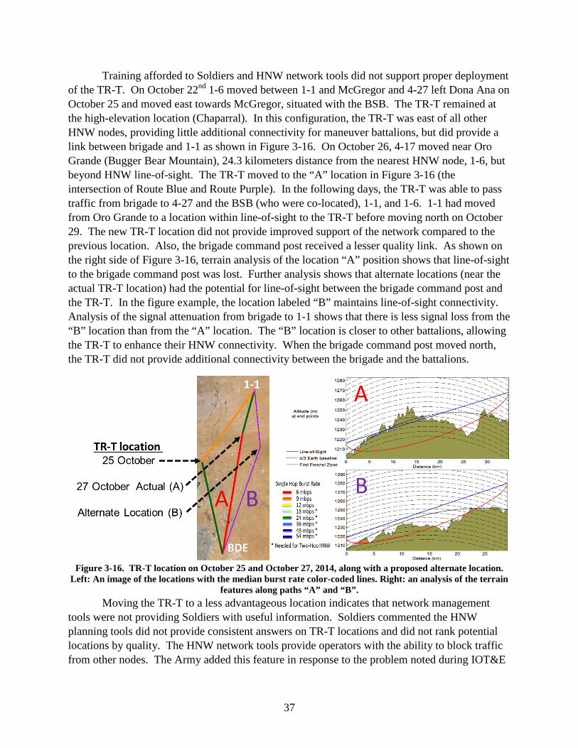
37
Training afforded to Soldiers and HNW network tools did not support proper deployment of the TR-T. On October 22nd 1-6 moved between 1-1 and McGregor and 4-27 left Dona Ana on October 25 and moved east towards McGregor, situated with the BSB. The TR-T remained at the high-elevation location (Chaparral). In this configuration, the TR-T was east of all other HNW nodes, providing little additional connectivity for maneuver battalions, but did provide a link between brigade and 1-1 as shown in Figure 3-16. On October 26, 4-17 moved near Oro Grande (Bugger Bear Mountain), 24.3 kilometers distance from the nearest HNW node, 1-6, but beyond HNW line-of-sight. The TR-T moved to the “A” location in Figure 3-16 (the intersection of Route Blue and Route Purple). In the following days, the TR-T was able to pass traffic from brigade to 4-27 and the BSB (who were co-located), 1-1, and 1-6. 1-1 had moved from Oro Grande to a location within line-of-sight to the TR-T before moving north on October 29. The new TR-T location did not provide improved support of the network compared to the previous location. Also, the brigade command post received a lesser quality link. As shown on the right side of Figure 3-16, terrain analysis of the location “A” position shows that line-of-sight to the brigade command post was lost. Further analysis shows that alternate locations (near the actual TR-T location) had the potential for line-of-sight between the brigade command post and the TR-T. In the figure example, the location labeled “B” maintains line-of-sight connectivity. Analysis of the signal attenuation from brigade to 1-1 shows that there is less signal loss from the “B” location than from the “A” location. The “B” location is closer to other battalions, allowing the TR-T to enhance their HNW connectivity. When the brigade command post moved north, the TR-T did not provide additional connectivity between the brigade and the battalions.
Figure 3-16. TR-T location on October 25 and October 27, 2014, along with a proposed alternate location.
Left: An image of the locations with the median burst rate color-coded lines. Right: an analysis of the terrain features along paths “A” and “B”.
Moving the TR-T to a less advantageous location indicates that network management tools were not providing Soldiers with useful information. Soldiers commented the HNW planning tools did not provide consistent answers on TR-T locations and did not rank potential locations by quality. The HNW network tools provide operators with the ability to block traffic from other nodes. The Army added this feature in response to the problem noted during IOT&E

38
that moving PoPs could disrupt the HNW network. Soldiers using these features in an improper manner can reduce the effectiveness of HNW. As an example, on October 26 and October 27 4-27 blocked the HNW link from the BSB (4-27 was a preferred neighbor of the BSB) even though they were stationary and separated by less than 1.2 kilometers.
During FOT&E 2, the TR-T could connect four to five command posts. Although nearest neighbor restrictions were lifted on the October 20, the number of TR-T-supported nodes does not increase, as seen in Figure 3-17, which shows how many HNW neighbors the TR-T maintained by hour (based on 10-second samples). Adjusting nearest neighbor parameters did not improve HNW connectivity.
Figure 3-17. Number of TR-T Neighbors (HNW Connections) during FOT&E 2
On October 24, a TCN to TCN link of 26 kilometers was observed consistently over a period of 10 hours (from 10:00 to 20:00 UTC time) from 4-27 to 1-1. While the Army stated this is an example of HNW effectiveness, this link provided little support to the unit’s mission. This 26-kilometer link supported a marginal 9 Mbps link burst rate and did not support significant user traffic for the majority of time. The upper portion of Figure 3-18 shows the link’s burst rates over time and the lower half shows the corresponding data rate. The region of HNW connectivity is highlighted. Over the entire day of HNW connectivity, the links supported 70 kbps of traffic in each direction between 4-27 and 1-1. This traffic is mostly network overhead and not associated with mission data.

39
Figure 3-18. HNW Connectivity between 4-27 and 1-1 on October 24 from approximately 10:00 to
20:00 UTC
Soldier Network Extension (SNE)
During FOT&E 2, the SNE with CNR Gateway was operationally effective and supported the unit’s mission with extended CNR coverage, VOIP phone calls, chat, and mission command applications.
During IOT&E, the SNE demonstrated poor data throughput, which did not allow Soldiers to use mission command applications or conduct successful on-the-move VoIP calls. After IOT&E, the Army adjusted the SNE’s data transfer configuration (buffering), removed the Command Post of the Future mission command application, and ensured the use of the more efficient WIN-T VoIP application.

40
DOT&E reported after the FOT&E 1 conducted at the Network Integration Evaluation 13.2 in May 2013 that the SNE was useful for VoIP, but not for most other functions. SNE reliability, combined with complex start-up and reboot procedures, provided a negative user experience for overall SNE effectiveness. At FOT&E 1, the SNE CNR Gateway was not effective as 10 out of 16 attempts at establishing the CNR Gateway were unsuccessful.
Capacity and VoIP
Figure 3-19 shows the distribution of the SNE total load for IOT&E, FOT&E 1, and FOT&E 2. During FOT&E, the SNE supported sufficient traffic load to support the intended functions of the SNE’s mission command applications.
Figure 3-19. SNE Total Load at IOT&E, FOT&E, and FOT&E 2
The SNE’s ability to support VoIP phone was operationally effective. During FOT&E 1, the SNE supported data throughput to conduct VoIP calls, but the utility of VoIP was limited by long call setup times with 12 percent of phone calls experiencing a wait time of 30 seconds or more. During FOT&E 2, the long call set-up times were reduced to 1.5 percent. Figure 3-20 shows FOT&E 2 Mine-Resistant Ambush Protected All-Terrain Vehicle (MATV) SNE user responses to the capability provided by the VoIP softphone. The majority of Soldiers found the VoIP softphone useful to support the unit’s mission.

41
Figure 3-19. MATV SNE Users’ Responses to the Capability Provided by VoIP
Mission Command Application
The SNE and PoP mission applications were operationally effective. Soldiers made great use of the WIN-T Chat application during unit operations. MATV SNE users found the back seat display useful and applications, such as Tactical Ground Reporting (TIGR) system, to be effective. SNE users noted in the focus groups that “lite” versions of the software, such as TIGR “lite,” did not provide the full suite of needed capabilities.
During FOT&E 1, Soldiers using the SNE experienced a high rate of system reboots, which reduced the effectiveness of mission command applications. Figure 3-21 shows the MATV SNE user ratings of the improved graphical user interface used in FOT&E 2. MATV SNE Soldiers found that the new user interface assisted them with operating mission command applications and assisted with accomplishing their mission.
Figure 3-21. MATV SNE Responses to the Ability of the WIN-T Multi Domain Atlas (MDA) to Provide Ease
in Completing the Mission

42
Combat Network Radio Gateway
During FOT&E 2, the CNR Gateway was operationally effective. As shown in Figure 3-22, the Army simplified the user interface for the CNR gateway. The left image provides the old interface, and the right provides the new interface.
Figure 3-22. Old (left) and New (right) CNR Gateway Display
During FOT&E 2, the CNR Gateway provided a useful capability to commanders to monitor distant CNR networks. By using the CNR Gateway, brigade and battalion commanders can obtain situational awareness from the forward areas of combat. The CNR Gateway was not as useful for company commanders who were located near their company/platoon operational areas.
Figure 3-23 shows the mixed opinions on the capability provided by CNR Gateway in rating the comment, “I was able to bridge my unit network with external units with the CNR gateway.” Although some Soldiers were positive, there were negative comments and some “N/A” comments, indicating that some respondents never used the CNR Gateway during FOT&E 2. Figure 3-24 shows the Soldiers’ assessment of CNR Gateway phone calls, which were positive.
Figure 3-23. Responses to the Survey Question on the Capability of CNR Gateway to Bridge Networks

43
Figure 3-24. Percentage of Calls Rated Bad to Excellent by Unit
Stryker Integration
The Stryker PoP and SNE were operationally effective and similar to the effectiveness demonstrated by the MATV PoP and SNE. Stryker SNEs exhibited a higher rate of satellite “acquire” and “align” states than MATV SNEs. This may have been due to the limited number of Stryker SNE and Stryker PoPs, and the differences in mission, location, and usage. Suitability problems (described in Section Four) interfere with the unit’s employment of the Stryker PoP and SNE.

44
This page intentionally left blank.

45
Section Four Operational Suitability
The WIN-T Increment 2 suitability evaluation for FOT&E 2 focused on those items that were not operationally suitable during IOT&E and FOT&E 1. During IOT&E, the WIN-T Increment 2 system was not operationally suitable. During FOT&E 1, the Tactical Communications Node, Tactical Relay – Tower, and Network Operations and Security Center were operationally suitable. The Vehicle Wireless Package (VWP) was operationally suitable as it was reliable, but not maintainable. The Point of Presence (PoP) and Soldier Network Extension (SNE) on-the-move platforms were not operationally suitable because they were not reliable, not maintainable, required frequent reboots, and startup/shutdown procedures were far too complex.
During FOT&E 2, the Army measured the reliability and maintainability characteristics of the following five WIN-T Increment 2 configuration items.
• VWP
• Mine-Resistant Ambush Protected All-Terrain Vehicle (M-ATV) PoP
• Stryker PoP
• M-ATV SNE
• Stryker SNE
During FOT&E 2, the VWP, the M-ATV PoP, and M-ATV SNE were operationally suitable. The Stryker PoP and Stryker SNE were not operationally suitable. As shown in Table 4-1, the WIN-T PoP met reliability requirements for both the M-ATV and Stryker variants. The M-ATV SNE met reliability requirements, but the Stryker SNE did not meet reliability requirements. The Stryker SNE met the 30-minute maintainability requirement. Neither the M-ATV PoP, Stryker PoP, nor M-ATV SNE met the maintainability requirement, and the maintainability of the VWP could not be assessed (no failures were observed in the test). The Army reduced the complexity of PoP and SNE operations and troubleshooting, and reduced the time required for startup and shutdown of these configuration items. The Stryker PoP and SNE presented Soldiers with significant human factors engineering and integration issues that interfered with the unit’s performance of mission operations. These Stryker WIN-T deficiencies include:
• Position of WIN-T displays in front of gunner position
• WIN-T antennas prevent 360 degree gun coverage
• WIN-T operations with engine off can drain batteries to level that they must be replaced
• Operating WIN-T on vehicle power does not allow “Silent Watch” operations

46
Table 4-1. FOT&E 2 WIN-T Increment 2 Operational Suitability Configuration Item Suitable Maintainable Reliable
VWP Yes Not Assessed1 Yes
M-ATV PoP Yes No Yes
Styker PoP No No Yes
M-ATV SNE Yes No Yes
Stryker SNE No Yes No 1With one 3-minute maintenance action, not able to assess VWP Mean Time To Repair (MTTR). PoP – Point of Presence; SNE – Soldier Network Extension; VWP – Vehicle Wireless Package; M-ATV – Mine Resistant Ambush Protected (MRAP) All-Terrain Vehicles (M-ATVs)
Requirement Changes
The Army modified the Mean Time Between Essential Function Failure (MTBEFF) reliability requirements for WIN-T Increment 2 three times since the publishing of the original Capability Production Document. In most cases, these modifications reduced reliability requirements and were based upon changing three variables that determine MTBEFF.
• Mission Duration – length (hours) of projected unit mission
• Mission Reliability – probability percentage that system will complete mission without failure
• Utilization Rate – percentage of system operation within mission pulse duration
Prior to the May 2012 IOT&E, the Army reduced the mission duration from a 96-hour division value to the 72-hour brigade value. Prior to the May 2013 FOT&E 1, the Army reduced mission reliability from 90 percent to 80 percent. Prior to the October 2014 FOT&E 2, the Army modified the utilization rates for the WIN-T configuration items based on usage rates observed at the May 2012 IOT&E.
Table 4-2 shows the MTBEFF requirement changes that resulted from the Army’s modifications of the WIN-T Increment 2 reliability variables. Lower reliability requirements result in increased life-cycle support costs through the increased number of required repair parts, maintenance man-hours, and a larger logistical footprint.

47
Table 4-2. Historical MTBEFF Requirements in Hours
Original CPD
November 2008
Mission Duration Adjustment
February 2012
Mission Reliability Adjustment May 2013
Utilization Adjustment
October 2014
TCN 900 664 314 303
PoP 900 385 182 144
SNE 300 529 250 184
VWP 900 94 45 97
TR-T 900 308 146 142
NOSC 900 463 219 216
TCN – Tactical Communications Node; PoP – Point of Presence; SNE – Soldier Network Extension; VWP – Vehicle Wireless Package; Tactical Relay – Tower; NOSC – Network Operations and Security Center
Reliability
During FOT&E 2, the M-ATV PoP, Styker PoP, M-ATV SNE, and VWP were reliable. The Styker SNE was not reliable. The Stryker SNE did not meet its MTBEFF requirement, but it demonstrated borderline results compared to the requirement. Table 4-3 provides the point estimates and the 1-sided 80 percent Lower Confidence Bounds (LCBs) for MTBEFF for the four WIN-T Increment 2 operational tests. During FOT&E 2, the Stryker and M-ATV PoPs met the Army’s revised requirement of 144 hours MTBEFF at the 80 percent LCB. The M-ATV PoP demonstrated sufficient reliability to meet the MTBEFF requirement assessed during FOT&E. The M-ATV SNE met the Army’s revised MTBEFF requirement of 184 hours at the 80 percent LCB, but the Stryker SNE did not meet the requirement. The M-ATV SNE demonstrated sufficient reliability to meet the MTBEFF requirement assessed during FOT&E. The VWP had no failures during FOT&E 2. A point estimate cannot be calculated. During FOT&E, the VWP met its reliability requirement. Reliability assessments were performed using the 80 percent LCB to maintain consistency with the IOT&E and FOT&E 1 assessments.
Table 4-3. Point Estimate and 80% Lower Confidence Bound MTBEFF
1This column has the Stryker values for the Point of Presence (PoP) and Soldier Network Extension (SNE) and the High-Mobility Multipurpose Wheeled Vehicle (HMMWV) values for the Vehicle Wireless Package (VWP). 2The VWP had no failures. LUT – Limited User Test; M-ATV – Mine Resistant Ambush Protected (MRAP) All-Terrain Vehicles
Point Estimate ( 80% Lower Confidence Bounds) MTBEFF
FOT&E 2 MTBEFF
Requirement
LUT M-ATV
IOT&E M-ATV
FOT&E M-ATV
FOT&E 2 M-ATV
FOT&E 2 Stryker PoP/SNE & HMMWV VWP1
PoP 144 87 (73) 167 (128) 112 (83) 377 (238) 307(167)
SNE 184 49 (45) 156 (137) 230(195) 519 (424) 183 (144)
VWP* 97 226 (143) 238 (157) 304(165) -2 (1,158) -* (624)

48
Table 4-4 shows the mission reliability estimates and the two-sided MTBEFF confidence intervals and point estimate for each of the configuration items compared to the requirement, which is based on an 80 percent, 1-sided lower confidence on the mission reliability. Mission reliability is the probability that a unit could complete a 72-hour brigade-level mission using a WIN-T Increment 2 configuration item without incurring an EFF. The formula used to calculate mission reliability is:
Where x is the mission duration and U is the rate of utilization. Table 4-4 includes the mission reliability calculated using both the October 2014 reliability requirement utilization rates and the utilization rates observed during operational test. Utilization rates demonstrated in FOT&E 2 were higher than those used to modify the reliability requirement (based upon IOT&E) as shown in Table 4-5.
𝑅(𝑥) = 𝑒𝑥𝑒 � −𝑥∙𝑈𝑀𝑀𝑀𝑀𝑀𝑀
�

49
Table 4-4. Mission Reliability Estimates
Operating Hours
Essential Function Failures
FOT&E2 Requirement
MTBEFF Point Estimate (two-sided 80%
CI)
Mission Reliability Point Estimate
(two-sided 80% CI) MTBEFF 1-sided
80% LCB4 OMS/MP2(2014) FOT&E 23
POP M-ATV 1,885 5 144
377 (203-775)
92% (85%-96%)
90% (82%-95%) 238
Stryker 921 3 144 307
(138-836) 90%
(79%-96%) 87%
(74%-95%) 167
SNE M-ATV 11,417 22 184
519 (389-703)
92% (90%-94%)
89% (83%-92%) 424
Stryker 2,921 16 184 183
(130-282) 80%
(73%-88%) 73%
(64%-81%) 144
VWP1 M-ATV 1,863 0 97 - - - 1,158
HMMWV 1,005 0 97 - - - 624 1As it had no failures, the Vehicle Wireless Package (VWP) Mean Time Between Essential Function Failure (MTBEFF) point estimate, two-sided confidence interval (CI) and mission reliability cannot be calculated. 2OMS/MP – Operational Mission Summary/Mission Profile; M-ATV – Mine Resistant Ambush Protected (MRAP) All-Terrain Vehicles; PoP – Point of Presence; SNE – Soldier Network Extension 3FOT&E2 mission reliability was calculated using the observed utilization at Network Integration Evaluation (NIE) 15.1. Values are given in Table 4-5. 4The MTBEFF 1-sided 80% lower confidence bound (LCB) is provided for comparison to previous test reports.

50
This page intentionally left blank.

51
Table 4-5. Reliability Requirement and FOT&E 2 Observed Utilization Rates
WIN-T Configuration Item
October 2014 Reliability
Requirement Utilization Rates
FOT&E 2 Observed Utilization Rates
PoP 45% 58.3%
SNE 57.8% 80.9%
VWP 30.5% 59.6% PoP – Point of Presence; SNE – Soldier Network Extension; VWP – Vehicle Wireless Package
Reliability and mission reliability are based upon WIN- Increment 2 hardware and software failures. Support equipment failures are not included in the MTBEFF estimates above, consistent with the Army’s failure definition scoring criteria, and with the IOT&E and FOT&E assessments. Table 4-6 shows MTBEFFs and mission reliability for PoP and SNE when the failures associated with the vehicle and other support equipment are included (e.g. a vehicle problem causes WIN-T to fail) using observed FOT&E 2 utilization rates. Soldiers idle M-ATV and Stryker vehicles to provide power and cooling for operating WIN-T Increment 2 configuration items. Excessive at-the-halt idle time increases vehicle failures. Table 4-6 provides a representation of the commander’s experience with WIN-T Increment 2 by including vehicle and support equipment failures. When vehicle failures are included, the PoP and SNE systems’ mission reliability is lowered.
Table 4-6. MTBEFF and Reliability Estimates with Support Equipment Failures
WIN-T Vehicle Op Hours WIN-T EFFs Vehicle/Support EFFs
MTBEFF PE
Mission Reliability
PE1
PoP M-ATV 1,885 11 2 111 69%
Stryker 921 4 7 62 51%
SNE M-ATV 11,417 32 1 294 82%
Stryker 2,282 22 5 112 59% 1Mission reliability calculated using FOT&E observed utilization rates PoP – Point of Presence; SNE – Soldier Network Extension; EFF – Essential Function Failure; M-ATV – Mine Resistant Ambush Protected (MRAP) All-Terrain Vehicle; PE – Point Estimate
Maintainability
During FOT&E 2, the Stryker SNE met the 30-minute Mean Time To Repair (MTTR) requirement. Table 4-7 summarizes the MTTR point estimates for the configuration items evaluated during FOT&E 2 compared to previous operational tests. FOT&E 2 repair times were consistent with values from previous tests. The confidence interval shown for FOT&E 2 is based on a log-normal distribution assumption. The Stryker SNE point estimate met the maintainability requirement of 30 minutes. Because there was one 3-minute VWP event that required maintenance action, MTTR could not be calculated.

52
Table 4-7. Mean Time to Repair (MTTR) Point Estimates (80% confidence levels are provided for the FOT&E 2 results)
Requirement: 30 Minutes IOT&E Point Estimate
FOT&E Point Estimate
FOT&E 2 Point Estimate
(80% Confidence Bounds)
POP M-ATV 105 35 87 (33-203)
Stryker N/A N/A 41 (23-83)
SNE M-ATV 57 49 44 (27-62)
Stryker N/A N/A 25 (19-42)
VWP (all variants) 43 119 N/A PoP – Point of Presence; SNE – Soldier Network Extension; M-ATV – Mine Resistant Ambush Protected (MRAP) All-Terrain Vehicle (M-ATV)
Figure 4-1. Troubleshooting Survey Question Results
The Army improved the PoP and SNE Multi-Display Atlas (MDA) display to provide both an improved user interface and easier-to-use troubleshooting procedures to assist the crew identify, as well as respond to failures. Soldiers found the troubleshooting procedures easier to use compared to the previous procedures used during FOT&E 1. While the new troubleshooting procedures were preferred to the previous ones, Soldiers stated that the new procedures provided less troubleshooting options for the advanced user (compared to the previous procedures). Figure 4-1 shows the Soldiers’ views on the new troubleshooting procedures.
During FOT&E 2, Soldiers’ success in troubleshooting WIN-T problems without a Field Service Representative (FSR) improved compared to IOT&E yet remains comparable to FOT&E. Table 4-8 shows the unit success rate for IOT&E, FOT&E 1, and FOT&E 2. With a
05
10152025
StronglyDisagree
Disagree Agree Strongly Agree
Troubleshooting
I prefer the new WIN-T Inc 2 troubleshooting procedures insteadof the old WIN-T Inc 2 troubleshooting procedures.
The SNE/PoP WIN-T Display provides adequate information fortroubleshooting.
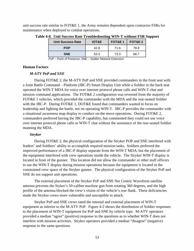
53
unit success rate similar to FOT&E 1, the Army remains dependent upon contractor FSRs for maintenance when deployed to combat operations.
Table 4-8. Unit Success Rate Troubleshooting WIN-T without FSR Support Unit Success Rate IOT&E FOT&E 1 FOT&E 2
POP 42.8 71.6 78.8
SNE 53.3 73.3 66.7 PoP – Point of Presence; SNE – Soldier Network Extension
Human Factors
M-ATV PoP and SNE
During FOT&E 2, the M-ATV PoP and SNE provided commanders in the front seat with a Joint Battle Command – Platform (JBC-P) Smart Display Unit while a Soldier in the back seat operated the WIN-T MDA for voice over internet protocol phone calls and WIN-T chat and mission command applications. The FOT&E 2 configuration was reversed from the majority of FOT&E 1 vehicles, which provided the commander with the MDA and the rear-seated Soldier with the JBC-P. During FOT&E 1, DOT&E found that commanders wanted to focus on leadership and fighting the battle, not on operating WIN-T. JBC-P provides the commander with a situational awareness map display to conduct on-the move operations. During FOT&E 2, commanders preferred having the JBC-P capability, but commented they could not use voice over internet protocol phone calls or WIN-T chat without the assistance of the rear-seated Soldier manning the MDA.
Stryker
During FOT&E 2, the physical configuration of the Stryker POP and SNE interfered with leaders’ and Soldiers’ ability to accomplish required mission tasks. Soldiers preferred the improved performance of a JBC-P display separate from the WIN-T MDA, but the placement of the equipment interfered with crew operations inside the vehicle. The Stryker WIN-T display is located in front of the gunner. This location did not allow the commander or other staff officers to use the WIN-T display during mission operations because the equipment is located in the constrained crew space of the Stryker gunner. The physical configuration of the Stryker PoP and SNE do not support unit operations.
The external placement of the Stryker PoP and SNE Net Centric Waveform satellite antenna prevents the Styker’s 50-caliber machine gun from rotating 360 degrees, and the high profile of the antenna blocked the crew’s vision of the vehicle’s rear flank. These deficiencies made the Stryker crews more vulnerable and susceptible to attack.
Stryker PoP and SNE crews rated the internal and external placement of WIN-T equipment as inferior to the M-ATV PoP. Figure 4-2 shows the distribution of Soldier responses to the placement of WIN-T equipment for PoP and SNE by vehicle type. M-ATV operators provided a median “agree” (positive) response to the questions as to whether WIN-T does not interfere with mission activities. Stryker operators provided a median “disagree” (negative) response to the same questions.

54
Figure 4-2. Survey Results on the Internal and External Integration of WIN-T
Increment 2 Equipment on the PoP and SNE
Complexity
During FOT&E 2, the PoP and SNE were less complex to operate and troubleshoot and demonstrated a faster startup and shutdown time. During FOT&E 1, the test unit experienced difficulty with the complexity and lengthy startup/shutdown times of the WIN-T Increment 2. During FOT&E 1, when the PoP and SNE failed, the operators needed to complete a complicated and order-sensitive restart. A single mistake during this process often required returning to the beginning of the process. Frustrated Soldiers would often turn off power, which would further extend their restart times and produce equipment failures. Since FOT&E 1, the Army improved WIN-T Increment 2 to simplify operation and troubleshooting and reduce the amount of time needed to start, shut down and reboot the PoP or SNE. While the previous procedures were geared towards a Signal Maintainer, the new procedures are intended for the general purpose user. The Army published a step-by-step troubleshooting guide available on the MDA.
The revised MDA user interface provides an increased viewing area and simplifies the user’s experience for operating and troubleshooting WIN-T Increment 2. Figure 4-3 provides the previous and revised WIN-T MDA user interfaces. The revised WIN-T interface simplifies operations, but limits the user’s view into the network and options available during troubleshooting.
Figure 4-3. Previous (left) and Revised (right) WIN-T MDA User Interface
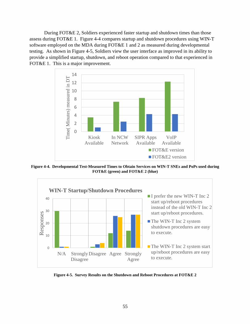
55
During FOT&E 2, Soldiers experienced faster startup and shutdown times than those assess during FOT&E 1. Figure 4-4 compares startup and shutdown procedures using WIN-T software employed on the MDA during FOT&E 1 and 2 as measured during developmental testing. As shown in Figure 4-5, Soldiers view the user interface as improved in its ability to provide a simplified startup, shutdown, and reboot operation compared to that experienced in FOT&E 1. This is a major improvement.
Figure 4-4. Developmental Test-Measured Times to Obtain Services on WIN-T SNEs and PoPs used during
FOT&E (green) and FOT&E 2 (blue)
Figure 4-5. Survey Results on the Shutdown and Reboot Procedures at FOT&E 2
0
2
4
6
8
10
12
14
KioskAvailable
In NCWNetwork
SIPR AppsAvailable
VoIPAvailable
Tim
e( M
inut
es) m
easu
red
in D
T
FOT&E versionFOT&E2 version
0
10
20
30
40
N/A StronglyDisagree
Disagree Agree StronglyAgree
Res
pons
es
WIN-T Startup/Shutdown Procedures I prefer the new WIN-T Inc 2start up/reboot proceduresinstead of the old WIN-T Inc 2start up/reboot procedures.
The WIN-T Inc 2 systemshutdown procedures are easyto execute.
The WIN-T Inc 2 system startup/reboot procedures are easyto execute.

56
Failure Modes
Figures 4-6 and 4-7 show the PoP and SNE failure modes by vehicle type. Each section represents the fraction of failures that were Essential Function Failures (EFFs) attributed to WIN-T; EFFs attributed to support equipment; non-EFFs attributed to WIN-T; or non-EFFs attributed to support equipment. The WIN-T EFFs are further divided by hardware and software failures. Non-EFFs degrade the capability of the configuration item and require maintenance. The equipment can function in its degraded state until maintenance can be performed.
As shown by the EFF grey/blue pie charts below, the majority of WIN-T EFFs are due to software failures. For the PoP, support equipment EFFs provide the majority of WIN-T failures in both the Stryker and M-ATV variants. For both the Stryker PoP and Stryker SNE, EFFs outnumber non-EFFs. Figure 4-8 shows the average failures per configuration item (number of failures divided by number of configuration items) for the Stryker PoP, M-ATV PoP, Stryker SNE, and M-ATV SNE.
Figure 4-6. Stryker and M-ATV PoP Failure Modes
Figure 4-7. Stryker and M-ATV SNE Failure Modes

57
Figure 4-8. Average Number of Failures per Configuration Item
During FOT&E 2, the Army reduced the frequency of recurring WIN-T Increment 2 failure modes and experienced new failure modes. During FOT&E 1, the PoP and SNE MDA and the Microwave Power Module -1000 (MPM-1000) produced 63 percent of EFFs for WIN-T configuration items. During FOT&E 2, the MDA and MPM-1000 accounted for 39 percent of PoP and SNE EFFs. The MDA was the cause of 5 of the 15 PoP EFFs and 14 of 41 SNE EFFs. In cases of MDA failure, the MDA would freeze, restart, or stop servicing peripheral devices and require reboot. The MPM-1000 modem was not the cause of any of the PoP EFFs and 3 of 41 SNE EFFs. Five of the fifteen PoP EFFs were associated with new failure modes related to the line-of-sight Highband Networking Waveform radio.
Datron Antenna
During FOT&E 2, the SNE Datron antenna internal Global Positioning System (GPS) drifted, which caused navigation errors that led to loss of satellite signal. The Army determined multiple causes for such loss, including alignment through a side-lobe during or after blockage, a software bug that caused the antenna to stop accepting GPS data, and problems updating GPS during high-angular momentum turns. The system could not automatically reacquire the satellite and had to be rebooted to regain connectivity. The Datron antenna caused 40 percent of Stryker SNE EFFs.
Following FOT&E 2, the Army implemented a Datron antenna fix and demonstrated the correction during two developmental tests in November and December 2014. The revised software includes an updated Kalman Filter, Doppler shift corrections, and revisions to how the GPS updates during at-the-halt to on-the-move transitions and on curved trajectories.
Stryker Batteries
Strykers commanders reported that WIN-T Strykers required more battery replacements than Stryker without WIN-T. In a focus group, one commander stated that he believed every WIN-T Stryker had at least one battery replacement. The 4-17 Infantry Battle Captain identified 28 battery replacements on four SNE and PoP Strykers. Table 4-9 summarizes this information.

58
Table 4-9. Summary of 4-17 Battle Captain WIN-T Stryker Battery Replacements CI User Date Replaced Notes
SNE
4-17 Platoon Leader
Oct 28-29 8 Two full sets of 4 replaced (no charge from alternator)
Stryker Team Chief
Oct 17-18 2 Batteries were drained below the threshold to be recharged.
POP
4-17 CDR
Oct 20 4 Batteries were not receiving charge.
Oct 9-10 8
Two full sets of 4 replaced (no charge from alternator). Batteries
were drained below the threshold to be recharged. Visibly damaged
noted.
4-17 S3
Oct 9-10 4 Four batteries were replaced.
Batteries were drained and operator systems were not able to turn on.
Oct 17-18 2 Two batteries were replaced.
Batteries were drained below the threshold to be recharged.
CI – confidence interval; SNE – Soldier Network Extension; PoP – Point of Presence; CDR – Commander; S3 – Battalion Operations Officer
The WIN-T Program Manager states that WIN-T has high power requirements that can drain the batteries of a Stryker vehicle below their charge threshold when the engine is not running. The WIN-T PoP and SNE are not fielded with an onboard generator, and rely on either vehicle engine power or the vehicle batteries to operate. Once the Stryker battery has been drained below 20 Volts, its ability to be recharged is diminished and the battery must be replaced. In addition to damaging batteries when not using engine power, Stryker vehicle batteries do not supply sufficient power to support Stryker Silent Watch operations (vehicle performing operations without the engine running) for the required four hours with WIN-T equipment in operation. Soldiers attempted to use the primary and auxiliary batteries at the same time using an “interconnect” feature in an attempt to extend Stryker WIN-T operations without engine power. Engaging the “interconnect switch” to join the two auxiliary and two primary batteries to extend the operations of the WIN-T PoP and SNE without engine power caused the failure of both the WIN-T Stryker primary and auxiliary batteries.
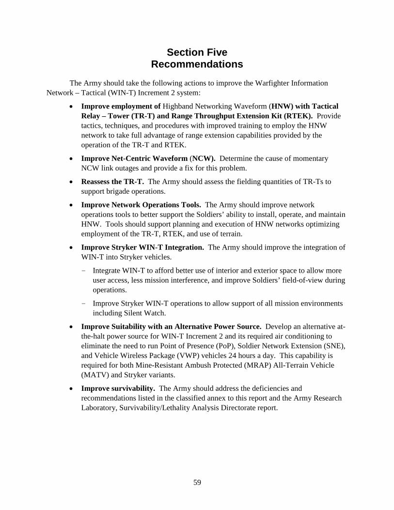
59
Section Five Recommendations
The Army should take the following actions to improve the Warfighter Information Network – Tactical (WIN-T) Increment 2 system:
• Improve employment of Highband Networking Waveform (HNW) with Tactical Relay – Tower (TR-T) and Range Throughput Extension Kit (RTEK). Provide tactics, techniques, and procedures with improved training to employ the HNW network to take full advantage of range extension capabilities provided by the operation of the TR-T and RTEK.
• Improve Net-Centric Waveform (NCW). Determine the cause of momentary NCW link outages and provide a fix for this problem.
• Reassess the TR-T. The Army should assess the fielding quantities of TR-Ts to support brigade operations.
• Improve Network Operations Tools. The Army should improve network operations tools to better support the Soldiers’ ability to install, operate, and maintain HNW. Tools should support planning and execution of HNW networks optimizing employment of the TR-T, RTEK, and use of terrain.
• Improve Stryker WIN-T Integration. The Army should improve the integration of WIN-T into Stryker vehicles.
- Integrate WIN-T to afford better use of interior and exterior space to allow more user access, less mission interference, and improve Soldiers’ field-of-view during operations.
- Improve Stryker WIN-T operations to allow support of all mission environments including Silent Watch.
• Improve Suitability with an Alternative Power Source. Develop an alternative at-the-halt power source for WIN-T Increment 2 and its required air conditioning to eliminate the need to run Point of Presence (PoP), Soldier Network Extension (SNE), and Vehicle Wireless Package (VWP) vehicles 24 hours a day. This capability is required for both Mine-Resistant Ambush Protected (MRAP) All-Terrain Vehicle (MATV) and Stryker variants.
• Improve survivability. The Army should address the deficiencies and recommendations listed in the classified annex to this report and the Army Research Laboratory, Survivability/Lethality Analysis Directorate report.


![[Challenge:Future] FoT](https://img.dokumen.tips/doc/110x75/55c9af84bb61eb9c328b476f/challengefuture-fot.jpg)


